the “cloud area padovana”: an openstack based iaas for the
TRANSCRIPT
PoS(ISGC2015)003
The “Cloud Area Padovana”: an OpenStack based IaaS for the INFN User Community
Cristina Aiftimiei
INFN CNAFViale Berti Pichat 6/2, I-40127 Bologna, ItalyIFIN-HHStr. Reactorului 30, Magurele, RomaniaE-mail: [email protected]
Paolo Andreetto
INFN, Sezione di PadovaVia Marzolo 8, I-35131 Padova, ItalyE-mail: [email protected]
Sara Bertocco
INFN, Sezione di PadovaVia Marzolo 8, I-35131 Padova, ItalyE-mail: [email protected]
Massimo Biasotto
INFN, Lab. Naz. di LegnaroVia Romea 4, 35020 Legnaro, ItalyE-mail: [email protected]
Fulvia Costa
INFN, Sezione di PadovaVia Marzolo 8, I-35131 Padova, ItalyE-mail: [email protected]
Alberto Crescente
INFN, Sezione di PadovaVia Marzolo 8, I-35131 Padova, ItalyE-mail: [email protected]
Alvise Dorigo
INFN, Sezione di PadovaVia Marzolo 8, I-35131 Padova, ItalyE-mail: [email protected]
Sergio Fantinel
INFN, Lab. Naz. di LegnaroVia Romea 4, 35020 Legnaro, ItalyE-mail: [email protected]
Federica Fanzago
INFN, Sezione di PadovaVia Marzolo 8, I-35131 Padova, ItalyE-mail: [email protected]
Eric Frizziero
INFN, Sezione di PadovaVia Marzolo 8, I-35131 Padova, ItalyE-mail: [email protected]
Michele Gulmini
INFN, Lab. Naz. di LegnaroVia Romea 4, 35020 Legnaro, ItalyE-mail: [email protected]
Michele Michelotto
INFN, Sezione di PadovaVia Marzolo 8, I-35131 Padova, ItalyE-mail: [email protected]
Massimo Sgaravatto
INFN, Sezione di PadovaVia Marzolo 8, I-35131 Padova, ItalyE-mail: [email protected]
Sergio Traldi
INFN, Sezione di PadovaVia Marzolo 8, I-35131 Padova, ItalyE-mail: [email protected]
Copyright owned by the author(s) under the terms of the Creative Commons Attribution-NonCommercial-ShareAlike Licence. http://pos.sissa.it
PoS(ISGC2015)003
The “Cloud Area Padovana” Cristina Aiftimiei et al.
Massimo Venaruzzo
INFN, Lab. Naz. di LegnaroVia Romea 4, 35020 Legnaro, ItalyE-mail: [email protected]
Marco Verlato1
INFN, Sezione di PadovaVia Marzolo 8, I-35131 Padova, ItalyE-mail: [email protected]
Lisa Zangrando
INFN, Sezione di PadovaVia Marzolo 8, I-35131 Padova, ItalyE-mail: [email protected]
At the end of 2013 INFN-Padova division and Legnaro National Laboratories (LNL) jointlystarted a new project aiming at expanding their grid-based computing and storage facility,mainly targeted to the needs of the big LHC experiments, with a cloud-based offering best suitedto address the needs of the smaller sized physics experiments carried out by the local teams.Despite the great success of the grid model in supporting large scale HEP experiments, itsadoption within smaller experiments has in fact been quite limited due to the well known lack offlexibility of the grid, e.g. in terms of: authentication/authorisation mechanisms; few OS andexecution environments supported; batch-like only access to resources (no interactivity); deeplearning curve for deploying/using services. This leads to a proliferation of several smallcomputing clusters, disconnected from the grid infrastructure, owned by each experiment andfully dedicated to it, often underutilised but not powerful enough to satisfy peak usage needsconcentrated in short periods (typically close to a scientific conference deadline). This scenarioclearly implies low efficiency and large waste of both human and hardware resources for thedata centre. The new cloud-based infrastructure is aimed at merging these scattered computingand storage resources in a unique facility that can serve the different experimental teams on-demand with the maximum of flexibility and elasticity made possible by the cloud paradigm.Leveraging the long-standing experience and collaboration as LHC Tier-2 of the Padova andLNL data centres, separated by 10 km but connected with a dedicated 10 Gbps optical link, the“Cloud Area Padovana” was built and put into production at the end of October 2014, after sixmonths of pre-production operations while a couple of pilot experiments tested the capabilitiesof the infrastructure with real use-cases. OpenStack was chosen as Cloud ManagementFramework for implementing a IaaS where computing and storage resources were sharedbetween the two data centres. However, several customisations and innovative services wereadded to the standard OpenStack deployment in order to address the users’ needs, ensure systemreliability and implement an efficient resource allocation. These concern the integration withOpenStack of authentication protocols like SAML and OpenID in order to enable userregistration and access at first via INFN-AAI and later via Italian (IDEM) and possibly otherinternational identity federations; the implementation of advanced functionalities for themanagement of users and projects by the IaaS administrators; the High Availability solutionadopted to implement fault-tolerance of the cloud services; the development of a fair-shareresource allocation mechanism analogous to the ones available in the batch system schedulersfor maximizing the usage of shared resources among concurrent users/projects. An overalldescription of the cloud infrastructure and its operations will be given, together with theperspective of the main scientific applications running on it.
International Symposium on Grids and Clouds (ISGC) 201515 -20 March 2015,Academia Sinica, Taipei, Taiwan
1 Speaker
2
PoS(ISGC2015)003
The “Cloud Area Padovana” Cristina Aiftimiei et al.
1. Introduction
The National Institute for Nuclear Physics (INFN) is the Italian research agency dedicatedto the study of the fundamental constituents of matter and the laws that govern them, under thesupervision of the Ministry of Education, Universities and Research (MIUR). It conductstheoretical and experimental research in the fields of sub-nuclear, nuclear and astroparticlephysics, and has been developing all along in house open ICT innovative solutions for its ownadvanced needs of distributed computing and software applications. INFN carries out researchactivities at two complementary types of facilities: divisions and national laboratories. The fournational laboratories, based in Catania, Frascati, Legnaro and Gran Sasso, house largeequipment and infrastructures available for use by the national and international scientificcommunity. Each of the 20 divisions and the 11 groups linked to the divisions or laboratories arebased at different university physics departments and guarantee close collaboration between theINFN and the academic world.
In particular, the INFN-Padova division and Legnaro National Laboratories (LNL) arelocated 10 km from each other, but their data centres, connected with a dedicated 10 Gbpsoptical data link, have operated for many years as an LHC Tier-2 grid facility [1] for both theALICE and CMS experiments. Thus, leveraging their long-standing collaborations, theyrecently started a new project aimed at providing a cloud-based offering of computing andstorage resources with the goal of addressing not only the needs of the already supported LHCexperiments, but also the needs of the numerous smaller sized physics experiments carried outby the local teams. The latter in fact could have until now only a limited support from the gridfacility due to the well known lack of flexibility of the grid technology in terms ofauthentication/authorisation mechanisms, execution environments, access to resources and deeplearning curve for deploying/using services. The project, called “Cloud Area Padovana”, choseas Cloud Management Framework one of the most popular and industry supported open sourcesolutions, OpenStack, that is also widely adopted in the scientific reference domain of INFN.
The paper describes the technical choices and the solutions adopted to provide a highlyavailable production ready Infrastructure as a Service (IaaS) platform across the Padova andLNL data centres for the benefit of the INFN user community.
The paper is organized as follows. Section 2 puts the present work in the context of thescientific cloud infrastructures, comparing Cloud Area Padovana with the order of magnitudeslarger size CERN Private Cloud. Section 3 shows the overall network architecture and servicesdeployment layout, focusing on the High Availability solutions adopted to implement the fault-tolerance of the cloud services. Section 4 presents the advanced functionalities implemented forthe management of users and projects to ensure an appropriate authorization work-flow afteruser authentication based on standard SAML protocol and federated identity managementsystems. Section 5 describes the original development of a fair-share cloud resource allocationmechanism analogous to the ones available in the batch system schedulers for maximizing theusage of shared resources among concurrent users and projects. Section 6 shows some examplesof applications already running in the production infrastructure, and finally Section 7 provides asummary and the future perspectives.
3
PoS(ISGC2015)003
The “Cloud Area Padovana” Cristina Aiftimiei et al.
2. Related Work
Cloud Area Padovana is clearly not the first and only project offering a cloud-based accessto network, computing and storage resources geographically distributed in different data centres.The most relevant project for the scientific reference domain of INFN is certainly the CERNOpenStack Private Cloud [2]. In 2011 CERN's IT team decided to build a private cloud thatwould need to integrate well with their very heterogeneous environment. They investigatedpotential components for new infrastructure tools and processes during 2011, and reviewed anumber of candidates. CERN's IT department selected OpenStack as Cloud ManagementFramework, and started working on it toward the end of 2011, building test clouds for physiciststo explore cloud technologies and test integration with CERN specific customizations. UsingScientific Linux, developed by CERN and Fermilab based on the Red Hat distribution, a cloudwas rapidly built with Compute, Image, Identity and Dashboard services. OpenStack waschosen since it was recognised to be the fastest growing open cloud community, working tobuild software that powers public and private clouds for a growing number of organizations,including Cisco WebEx, Comcast, eBay, HP, Intel, MercadoLibre, NeCTAR and Rackspace.Having a vibrant technology and developer open ecosystem around OpenStack allows to benefitfrom the work of the active contributors but also to use the local engineering skills to enhancethe product for others.
At the time of writing, CERN Private Cloud spans two data centres (CERN and Wigner, inHungary) connected by two 100 Gbps links, hosts more than 4700 hypervisors (120000 cores),11000 VMs and provides services to 1500 users and 1800 projects.
While CERN's experience was of great inspiration for the building of the Cloud AreaPadovana, some architectural design and some technical solutions choices were different:
Resource management:
● CERN Cloud uses OpenStack Nova Cells in their architecture to easily manage theexpansion of the cloud while keeping a single entry point for all the resources. TheCloud Area Padovana is much smaller, and therefore it was chosen not to partitionresources in Nova Cells, because this was considered not needed.
● CERN Cloud does not support live migration of instances between differentcompute nodes, since there is not a common file system among compute nodes andbecause of some constraints in the CERN network infrastructure. This is not thecase for the Cloud Area Padovana, where the live migration of instances wasconsidered an important feature to be implemented.
● CERN Cloud uses Ceph as storage backend for Image service (Glance) and BlockStorage service (Cinder). Cloud Area Padova chose instead GlusterFS as storagebackend, given the greater experience of the local engineering skills with thisproduct. GlusterFS is also used for the file system hosting the instances.
4
PoS(ISGC2015)003
The “Cloud Area Padovana” Cristina Aiftimiei et al.
● CERN Cloud uses Flume, Elastic Search and Kibana for monitoring the OpenStackstatus in all nodes. Cloud Area Padova chose instead to use Nagios and Ganglia asmonitoring tools, given the long-standing in house experience with these products,inherited from the grid era.
Networking:
● CERN Cloud still uses the deprecated Nova Network to integrate OpenStack withthe network infrastructure at CERN. Instances created in the CERN OpenStack arecreated in CERN public networks. Cloud Area Padovana chose instead to use theNeutron service with Open vSwitch and GRE tunneling for managing thenetworking of the whole cloud infrastructure, as described in section 3.2.
Authorization/Authentication
● In CERN Cloud the Keystone Identity service is integrated with the CERN SSOsystem by using the LDAP backend. Cloud Area Padovana chose instead to developsome extensions to both Keystone and Horizon Dashboard to allow OpenStack tointeract with the SAML-based INFN-AAI Identity Provider, and then with theIDEM Italian Federation. Moreover, complete separation of the authenticationphase, relying on external IdPs, from authorization phase taking place insideKeystone was implemented, as described in section 4.
On the other hand, some other choices were quite similar, e.g. the use of a configurationinfrastructure based on Puppet, the use of EPEL/RDO – RPM packages to install OpenStack,the use of HAProxy as load balancer in a High Availability configuration and of a RabbitMQcluster for the messaging queue.
5
PoS(ISGC2015)003
The “Cloud Area Padovana” Cristina Aiftimiei et al.
3. Architecture of the Cloud Area Padovana
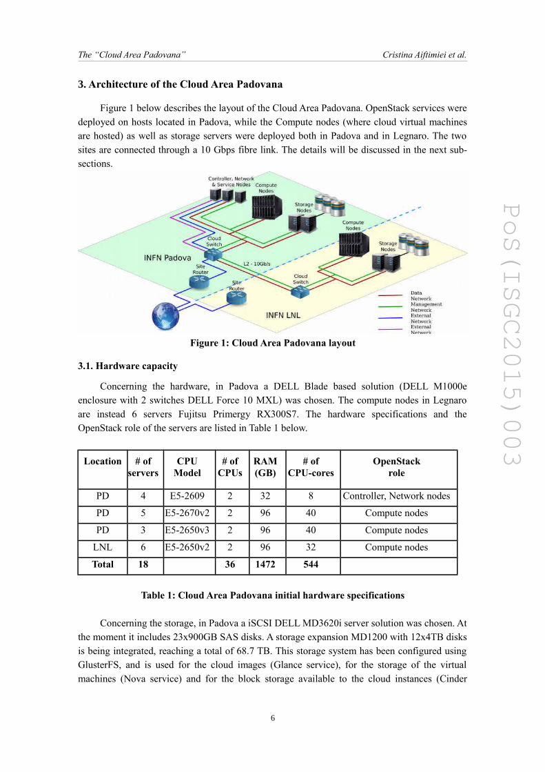
Figure 1 below describes the layout of the Cloud Area Padovana. OpenStack services weredeployed on hosts located in Padova, while the Compute nodes (where cloud virtual machinesare hosted) as well as storage servers were deployed both in Padova and in Legnaro. The twosites are connected through a 10 Gbps fibre link. The details will be discussed in the next sub-sections.
Figure 1: Cloud Area Padovana layout
3.1. Hardware capacity
Concerning the hardware, in Padova a DELL Blade based solution (DELL M1000eenclosure with 2 switches DELL Force 10 MXL) was chosen. The compute nodes in Legnaroare instead 6 servers Fujitsu Primergy RX300S7. The hardware specifications and theOpenStack role of the servers are listed in Table 1 below.
Location # ofservers
CPUModel
# ofCPUs
RAM(GB)
# ofCPU-cores
OpenStackrole
PD 4 E5-2609 2 32 8 Controller, Network nodes
PD 5 E5-2670v2 2 96 40 Compute nodes
PD 3 E5-2650v3 2 96 40 Compute nodes
LNL 6 E5-2650v2 2 96 32 Compute nodes
Total 18 36 1472 544
Table 1: Cloud Area Padovana initial hardware specifications
Concerning the storage, in Padova a iSCSI DELL MD3620i server solution was chosen. Atthe moment it includes 23x900GB SAS disks. A storage expansion MD1200 with 12x4TB disksis being integrated, reaching a total of 68.7 TB. This storage system has been configured usingGlusterFS, and is used for the cloud images (Glance service), for the storage of the virtualmachines (Nova service) and for the block storage available to the cloud instances (Cinder
6
PoS(ISGC2015)003
The “Cloud Area Padovana” Cristina Aiftimiei et al.
service). In Legnaro a Fibre Channel based system (DELL PowerVault MD3600F plus MD1200expansion) with 24x2TB disks was acquired instead. It will be used as general-purpose userstorage, also configured using GlusterFS.
3.2. Network layout
The cloud network configuration is based on three VLANs, each one associated to a classC network. The VLANs are partially shared between the local INFN-Padova division networkand the local Legnaro National Laboratories network. The two sites are connected through adedicated 10 Gbps Ethernet optical data link. The three networks are associated, in theOpenStack terminology, to the management, data/tunnel and public/external networks. Themanagement network connects all the servers hosting OpenStack services, plus a number ofancillary services that will be described in the next sections and are needed to manage, controland monitor the infrastructure and ensure its high availability. The management network usesprivate IP addresses, but can access the Internet through a dedicated NAT server. The datanetwork is used for virtual machines communications and connects the OpenStack Compute andNetwork nodes. It supports a 10 Gbps link and MTU > 1500 to allow GRE (Generic RoutingEncapsulation) [3] tunnels usage. Lastly, the public network connects the OpenStack servicesthat need to be reached from outside the LAN, i.e. the Horizon Dashboard, the Nova and EC2APIs and the Network nodes. In order to manage the internal cloud networks the use ofOpenStack Neutron service with Open vSwitch and GRE was chosen. Two Neutron providerrouters were defined: a first one for virtual machines that need to be reachable from outside; asecond one for virtual machines that only need SSH access from internal INFN-Padova or LNLLANs. The first router has the external gateway on the public network, and connects the class Csubnets of the 10.63 network. Each OpenStack project uses a separate subnet. Virtual machinesobtain their private IP addresses from internal DHCP servers, and can access the Internetthrough the NAT provided by Neutron, or obtain a floating IP from the public network in casethey need to offer services to the external world. The second router connects the class C subnetsof the 10.64 network, but has the external gateway towards the internal LANs. In this way theNAT is not used so that the virtual machines can be reached from the INFN-Padova and LNLinternal LANs directly by using their private IP addresses. For security reasons we chose toallow only connections from the LAN towards the virtual machines, and not vice-versa. Thesevirtual machines are at any rate allowed to access Internet through an external NAT, even if theycannot obtain a floating IP address. A special configuration was designed in order to providevirtual machines with high performance access to data located in storage systems external to thecloud. The L2 Neutron Agent software was installed on the storage servers, which wereequipped with two network interfaces: one on the management network and the other one on thedata network. Once all services start, the network bridges and GRE tunnels towards all thecomponents of the cloud infrastructure are automatically created. The only manual operationneeded is to add the new traffic flow to the local OpenFlow table. As this table is restored whena new Compute node is added to the cloud, a cron job may be necessary to execute a script tokeep it updated by adding the storage flow, if needed. The virtual machine access is possible bycreating an interface on the interconnection bridge, and by assigning to it the proper VLAN andan IP address on the same subnet of the virtual machine that need to be reached. Access to datacan be obtained e.g. via NFS or other protocols.
7
PoS(ISGC2015)003
The “Cloud Area Padovana” Cristina Aiftimiei et al.
3.3. High Availability service deployment layout
The business continuity is a very sensitive topic when services are exposed to users anddetermines their quality evaluation of the provider. In the case of OpenStack, the operationcontinuity is based on the redundancy of each physical node dedicated to the execution of thestack's components. The OpenStack guide suggests two ways of setting up its services in ahighly available mode:
● active/passive mode: the services are running on only one physical node of the clusterat any given time, but they can be moved from one node to another
● active/active mode: the services run at the same time on all nodes of the redundantcluster
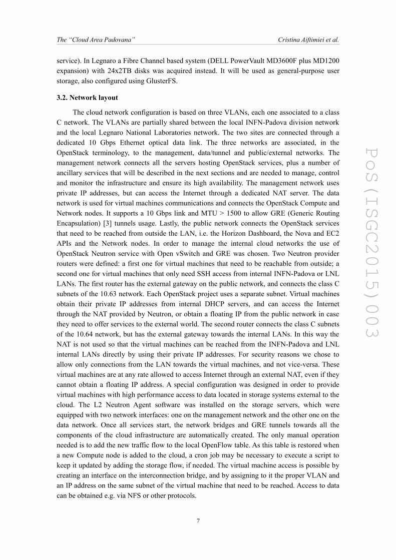
Even if there are cases in which distributed services can keep their internal statessynchronized and can be set up in high availability mode with both models, the high availabilityof stateful services is more achievable with the active/passive mode, in order to prevent datacorruption due to race condition. On the other hand OpenStack components are stateless (theystore their data on an external SQL database), as a consequence the active/active mode is alsosuitable for it. In our cloud farm we also considered the benefit of load balancing offered by anactive/active model using the lightweight, high performance and easy configurable HAProxy [4]daemon for the balancing of the incoming connections among the physical nodes, andKeepalived [5] for the Virtual IP movement between the HAProxy servers.
Figure 2: High Availability configuration
The three nodes running HAProxy and Keepalived are virtual machines running LinuxCentOS 6.6. HAProxy and Keepalived are not "stock" packages from EPEL; they werepackaged from recent stable releases that support respectively SSL front-end and unicastprotocol. The three virtual nodes are backed by the Proxmox virtualization software facility and
8
PoS(ISGC2015)003
The “Cloud Area Padovana” Cristina Aiftimiei et al.
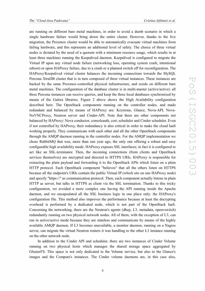
are running on different bare metal machines, in order to avoid a dumb scenario in which asingle hardware failure would bring down the entire cluster. However, thanks to the livemigration, the Proxmox cluster would be able to automatically evacuate virtual machines fromfailing hardware, and this represents an additional level of safety. The choice of three virtualnodes is dictated by the need of a quorum with a minimum resource usage, which results in atleast three machines running the Keepalived daemon. Keepalived is configured to migrate theVirtual IP upon any virtual node failure (networking loss, operating system crash, intentionalreboot) or upon HAProxy failure, due to a crash or a planned switch off for reconfiguration. TheHAProxy/Keepalived virtual cluster balances the incoming connections towards the MySQLPercona XtraDB cluster that is in turn composed of three virtual instances. These instances arebacked by the same Proxmox-controlled physical infrastructure, and reside on different baremetal machines. The configuration of the database cluster is in multi-master (active/active): allthree Percona instances can receive queries, and keep the three local databases synchronized bymeans of the Galera libraries. Figure 2 above shows the High Availability configurationdescribed here. The OpenStack components running on the controller nodes, and maderedundant and balanced by means of HAProxy are: Keystone, Glance, Nova-API, Nova-NoVNCProxy, Neutron server and Cinder-API. Note that there are other components notbalanced by HAProxy: Nova conductor, consoleauth, cert, scheduler and Cinder scheduler. Evenif not controlled by HAProxy, their redundancy is also critical in order to make the cloud IaaSworking properly. They communicate with each other and all the other OpenStack componentsthrough the AMQP daemon running in the controller nodes. For the AMQP implementation wechose RabbitMQ that was, more than one year ago, the only one offering a robust and easyconfigurable high availability mode. HAProxy exposes SSL interfaces; in fact it is configured toact like an SSL-terminator. Then, the incoming connections (from clients and OpenStackservices themselves) are encrypted and directed to HTTPS URIs. HAProxy is responsible forextracting the plain payload and forwarding it to the OpenStack APIs which listen on a plainHTTP protocol. Each OpenStack component "believes" that all the others listen on HTTPSbecause all the endpoint's URIs contain the public Virtual IP (which sits on one HAProxy node)and specify "https://" as communication protocol. Then, each component actually listens in plainHTTP as server, but talks in HTTPS as client via the SSL termination. Thanks to this trickyconfiguration, we avoided a more complex one having the API running inside the Apachedaemon, and we encapsulated all the SSL business logic in one place only: the HAProxy'sconfiguration file. This method also improves the performance because at least the decryptingoverhead is performed by a dedicated node, which is not part of the OpenStack IaaS.Concerning the networking, there are the Neutron's agents (dhcp, L3, metadata, openvswitch)redundantly running on two physical network nodes. All of them, with the exception of L3, canrun in active/active mode because they are stateless and communicate by means of the highlyavailable AMQP daemon. If L3 becomes unavailable, a monitor daemon, running on a Nagiosserver, can migrate the virtual Neutron routers it was handling to the other L3 instance runningon the other network node.
In addition to the Cinder API and scheduler, there are two instances of Cinder Volumerunning on two physical hosts which manages the shared storage space aggregated byGlusterFS. This space is not only dedicated to the Volume service, but also to the Glance'simages and the Compute's instances. The Cinder volume daemons are, in this case also,
9

PoS(ISGC2015)003
The “Cloud Area Padovana” Cristina Aiftimiei et al.
redundant and can both be addressed by the Cinder scheduler. Finally, all the Compute nodes(hypervisors) run their local instance of Nova compute process, which communicates with theController's services by means of the AMQP. All the hypervisors mount the shared GlusterFSfile system in their /var/lib/nova/instances and allow the system to perform a live migration ofthe virtual machines. In this way the system is tolerant to scheduled outages of the hypervisorsfor maintenance or upgrade of the software.
3.4. Infrastructure management and monitoring
3.4.1. Infrastructure management
A critical part of a cloud's scalability is the amount of effort that it takes to run the cloudinfrastructure. To minimize the operational cost of running our infrastructure, we analysed, setup and used an automated deployment and configuration infrastructure with a configurationmanagement system: Foreman together with Puppet. Combined, these systems greatly reducemanual effort and the chance of operator mistakes. Foreman is a system that automaticallyinstalls the operating system’s initial configuration and later coordinates centrally theconfiguration of all services. The hardware used for the cloud infrastructure is equipped withiDRAC (Integrated Dell™ Remote Access Controller Firmware), iLO (HP Integrated Lights-Out) or OpenManage interface so we can remotely operate on it and easily check the hardwarestatus. The Foreman instance is responsible for provisioning hosts via PXE and also acts asPuppet Server managing all nodes configurations, deployed on a single host. In the Foremanhost the following services are installed:
● the TFTP boot server● the DHCP Server for the cloud management and data subnets● the Puppet Master
Using Foreman different hosts can be built by installing them with different operatingsystems choosing the provisioning template and setting the partition table as needed. Usingcustomized Puppet classes, from the Web GUI a set of Puppet modules can be associated toeach host. Our infrastructure is mostly based on Red Hat Enterprise Linux derivatives likeScientific Linux and CentOS operating systems, but the possibility of deploying services usingUbuntu is also guaranteed. For each operating system we set up a custom set of kickstart orpreseed files which manage the packages installation, the partition table, the network interfaces,linux base configurations like selinux and iptables, some customizations to Puppet auth and conffiles. We defined hostgroups by assigning certain Puppet modules responsible with theconfiguration of: ntp, ssl-key access, Ganglia and Nagios monitoring agents and plugins. Allhosts are associated to respective hostgroups according to their roles in the infrastructure. TheOpenStack Controller and the OpenStack Network node are installed with a manual procedure,while all the OpenStack Compute nodes have been installed using a home-made, custom Puppetmodule. In this way we manage all the hosts of our cloud infrastructure from one point: theForeman Web GUI.
3.4.2. Monitoring
The servers hosting the storage system, the OpenStack services and the MySQL DB,HAProxy and RabbitMQ clusters are monitored by Ganglia and Nagios. Using custom Puppet
10
PoS(ISGC2015)003
The “Cloud Area Padovana” Cristina Aiftimiei et al.
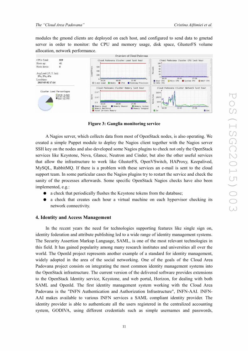
modules the gmond clients are deployed on each host, and configured to send data to gmetadserver in order to monitor: the CPU and memory usage, disk space, GlusterFS volumeallocation, network performance.
Figure 3: Ganglia monitoring service
A Nagios server, which collects data from most of OpenStack nodes, is also operating. Wecreated a simple Puppet module to deploy the Nagios client together with the Nagios serverSSH key on the nodes and also developed some Nagios plugins to check not only the OpenStackservices like Keystone, Nova, Glance, Neutron and Cinder, but also the other useful servicesthat allow the infrastructure to work like GlusterFS, OpenVSwitch, HAProxy, Keepalived,MySQL, RabbitMQ. If there is a problem with these services an e-mail is sent to the cloudsupport team. In some particular cases the Nagios plugins try to restart the service and check thesanity of the processes afterwards. Some specific OpenStack Nagios checks have also beenimplemented, e.g.:
● a check that periodically flushes the Keystone tokens from the database; ● a check that creates each hour a virtual machine on each hypervisor checking its
network connectivity.
4. Identity and Access Management
In the recent years the need for technologies supporting features like single sign on,identity federation and attribute publishing led to a wide range of identity management systems.The Security Assertion Markup Language, SAML, is one of the most relevant technologies inthis field. It has gained popularity among many research institutes and universities all over theworld. The OpenId project represents another example of a standard for identity management,widely adopted in the area of the social networking. One of the goals of the Cloud AreaPadovana project consists on integrating the most common identity management systems intothe OpenStack infrastructure. The current version of the delivered software provides extensionsto the OpenStack Identity service, Keystone, and web portal, Horizon, for dealing with bothSAML and OpenId. The first identity management system working with the Cloud AreaPadovana is the "INFN Authentication and Authorization Infrastructure", INFN-AAI. INFN-AAI makes available to various INFN services a SAML compliant identity provider. Theidentity provider is able to authenticate all the users registered in the centralized accountingsystem, GODIVA, using different credentials such as simple usernames and passwords,
11
PoS(ISGC2015)003
The “Cloud Area Padovana” Cristina Aiftimiei et al.
Kerberos tickets or X509 certificates. The result of authentication phase is stored into a SAMLauthentication assertion which is returned to the service. The service uses the authenticationassertion to identify the user. For any authenticated user the identity provider can publish a setof attributes retrieved from the accounting system. The composition of the attribute set dependson the privileges granted to the service that contacts the identity provider. The publishedattributes can feed both the authorization phase, carrying out an attribute-based access controlstrategy, and the business logic of the service. In the context of Cloud Area Padovana the serviceinteracting with the identity provider of INFN-AAI is the OpenStack web portal: the HorizonDashboard. The following subsections describe in more detail how the authentication andauthorization phases take place in Horizon.
4.1. User authentication and authorization
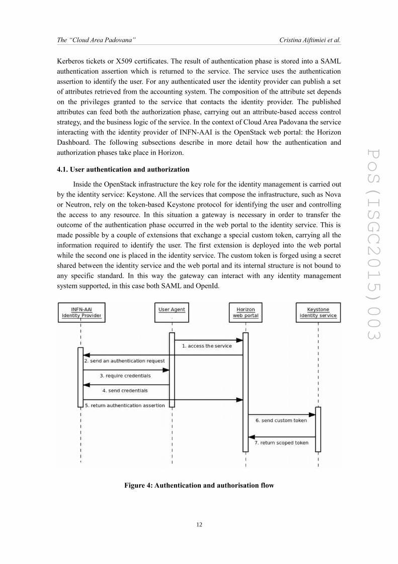
Inside the OpenStack infrastructure the key role for the identity management is carried outby the identity service: Keystone. All the services that compose the infrastructure, such as Novaor Neutron, rely on the token-based Keystone protocol for identifying the user and controllingthe access to any resource. In this situation a gateway is necessary in order to transfer theoutcome of the authentication phase occurred in the web portal to the identity service. This ismade possible by a couple of extensions that exchange a special custom token, carrying all theinformation required to identify the user. The first extension is deployed into the web portalwhile the second one is placed in the identity service. The custom token is forged using a secretshared between the identity service and the web portal and its internal structure is not bound toany specific standard. In this way the gateway can interact with any identity managementsystem supported, in this case both SAML and OpenId.
Figure 4: Authentication and authorisation flow
12
PoS(ISGC2015)003
The “Cloud Area Padovana” Cristina Aiftimiei et al.
Figure 4 above summarizes the operations that occur during the complete authenticationphase. The steps from 1 to 5 are the standard ones specified by the Web Browser Single Sign Onprofile of SAML. The step 6 represents the custom token exchange between the two extensionsdeveloped in the Cloud Area Padovana project. With step 7 the identity service, Keystone, oncethe extension has processed the custom token, returns the Keystone scoped token. The scopedtoken, according to the Keystone protocol, encompasses any information for accessing anOpenStack service as a member of a project. The key point of the solution developed in CloudArea Padovana is the complete separation of the authentication phase, which resorts to externalidentity management systems, from the authorization phase which takes place inside theOpenStack Identity service.
4.2. User registration
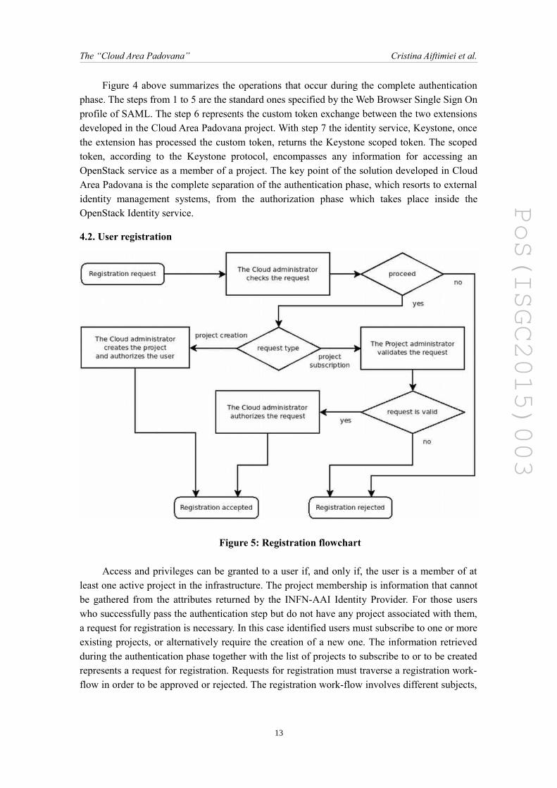
Figure 5: Registration flowchart
Access and privileges can be granted to a user if, and only if, the user is a member of atleast one active project in the infrastructure. The project membership is information that cannotbe gathered from the attributes returned by the INFN-AAI Identity Provider. For those userswho successfully pass the authentication step but do not have any project associated with them,a request for registration is necessary. In this case identified users must subscribe to one or moreexisting projects, or alternatively require the creation of a new one. The information retrievedduring the authentication phase together with the list of projects to subscribe to or to be createdrepresents a request for registration. Requests for registration must traverse a registration work-flow in order to be approved or rejected. The registration work-flow involves different subjects,
13

PoS(ISGC2015)003
The “Cloud Area Padovana” Cristina Aiftimiei et al.
each one with different roles and capabilities. In the current implementation two categories ofactors are defined: the cloud administrator and the project administrator. The cloudadministrator is the native role provided by any OpenStack installation that manages the cloud.It has all the privileges of users and projects and it is responsible, eventually, for accepting orrejecting the request for registration The project administrator is the user of the project that isresponsible for validating any new request for registration. Since a cloud administrator is notsupposed to know if a new user is allowed to be a member of an existing project, the projectadministrator is the reference required to solve this issue.
The complete registration work-flow is depicted in Figure 5 above. The very first step inthe flow is carried out by the cloud administrator who performs a preliminary check of therequest and sets several constraints such as the expiration date of the account. The followingsteps depend on the type of registration request. If it refers to a creation of a new project theregistration flow involves only the cloud administrator, who creates the project, grants accessand privileges to the user and declares the user as the first project administrator for the newproject. In case the request refers to a subscription to an existing project, the projectadministrator is committed to validate the membership of the user before the cloudadministrator concludes the registration forms. If the user is not recognized by the projectadministrator the request is rejected. When eventually the cloud administrator authorizes theuser, privileges and project membership are stored onto the OpenStack Identity service. Theentire registration flow is implemented in the OpenStack Horizon Dashboard with the followingelements:
● a user registration form by which the user can specify the projects to subscribe to orto be created, together with other useful information
● a panel for the registration request management, visible only by the cloudadministrator, and a set of pop-up menus dealing with different step of the flow
● a panel for the project subscriptions by which the project administrator can handlethe validation of the registration request
Figure 6: Horizon customisation enabling registration
14
PoS(ISGC2015)003
The “Cloud Area Padovana” Cristina Aiftimiei et al.
The elements above are registered into the web portal exploiting the extensionmechanisms of the framework. No changes in the code of the original Horizon Dashboard arerequired. A snapshot of the new form and panels is shown in Figure 6 above.
5. Fair-share scheduler
5.1. The resource static partitioning issue
Computing activities performed by user groups in the Public Research and in the PublicAdministrations are usually not constant over long periods of time (e.g. one year). The amountof computing resources effectively used by such user teams may therefore vary in a quitesignificant way. On these environments it is usual for the teams to stipulate with the DataCentres contracts for the provision of an average computing capacity to be guaranteed during along period (e.g. one year) rather than of an agreed amount of computing resources that shouldbe available at any given time. In these Data Centres new hardware resources are acquiredaccording to the user best estimates of the annual computing resources needed for their activitiesand partitioned among them. The partitioning policy is defined in terms of fractions of averageusage of the total available capacity (i.e. the percentage of the Data Centre’s computingresources each team has the right to use averaging over a fixed time window). In order torespect the contracts, the administrators have to enforce that each stakeholder team, at the end ofany sufficiently long period of time, and hence for the entire year, has its agreed average numberof resources. Moreover, since in general the request for resources is much greater than theamount of the available resources, it becomes necessary to seek to maximize their utilization byadopting a proper resource sharing model. In the current OpenStack model, the resourceallocation to the user teams (i.e. the projects) can be done only by granting fixed quotas. Suchan amount of resources cannot be exceeded by one group even if there are unused resourcesallocated to other groups. So, in a scenario of full resource usage for a specific project, newrequests are simply rejected. The static resource allocation model fits the economic model wellwhere users can benefit at most of the resources provided for in their contract but is not suitablein the public research context. Past experience has shown that, when resources are staticallypartitioned (e.g. via quota) among user teams, the global efficiency in the Data Centre’s resourceusage is usually quite low (often less than 50%). This resource allocation optimization problemhas already been tackled and solved in the past initially by the batch systems and subsequentlyby the grid model which was conceived on the awareness that Research Data Centre resourcesare limited. In particular such advanced batch systems, in opposition to the OpenStack staticmodel, adopt the dynamic allocation paradigm which allows a continuous full utilization of allavailable resources. This model is based on sophisticated scheduling algorithms (i.e. fair-share)in order to guarantee the resources' usage is equally distributed among users and groups byconsidering the portion of the resources allocated to them (i.e. share) and the resources alreadyconsumed. INFN has started to address this issue by enhancing the current OpenStack schedulercapabilities by providing the main batch system's features as a persistent queuing mechanism forhandling user requests as well as the adoption of the resources provisioning model based on theadvanced SLURM's Multifactor Priority strategy [6].
15
PoS(ISGC2015)003
The “Cloud Area Padovana” Cristina Aiftimiei et al.
5.2. The fair-share scheduling solution
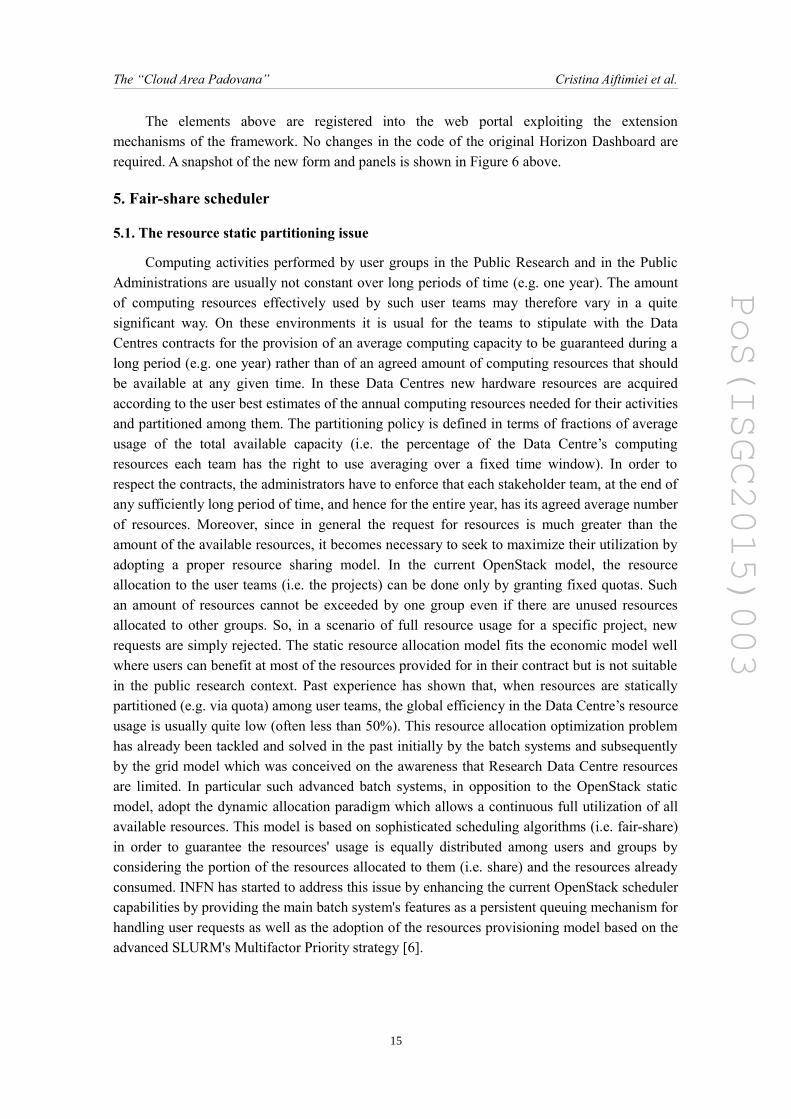
The OpenStack architecture is composed of a set of components each one having specificcapabilities. Nova scheduler is the component that determines the proper and available hostwhich best satisfies the user request for instantiating his virtual machine. Although Novascheduler provides scheduling features, it is far from the real batch systems logic. It is just aresource supplier, which processes the user requests sequentially (FIFO scheduling) and in casea request cannot be satisfied due to non-availability of hosts or the assigned user quota is fullyused, such requests will fail immediately and it will be lost. What is mainly missing in Novascheduler is a queuing mechanism for handling the user requests and a fair-share algorithm inthe resources provisioning which can guarantee at the same time the continuous full usage of allresources and the quota established for the different user teams. In the batch systemterminology, the fair-share is one of the main factors in the job priority formula whichinfluences the scheduling order of the queued jobs and its calculation is based on the historicalresource utilization of all users. The approach we adopted is to fill the gap between Novascheduler and the batch systems, by implementing a new component named FairShare-Scheduler which aims not to substitute the original scheduler, but to provide the missingadvanced scheduling logic without breaking the OpenStack's architecture. In particular theFairShare-Scheduler has been designed in order to be fully integrated in OpenStack andespecially to not require any changes on the existing scheduler. The schema in Figure 7 showsthe high level architecture and in particular highlights the interaction with other componentsinvolved in the scheduling activity.
Figure 7: FairShare scheduler architecture
A proper priority value, calculated by the FairShare-Manager, is assigned to every userrequest coming from the Horizon Dashboard or command line. The request is immediately
16
PoS(ISGC2015)003
The “Cloud Area Padovana” Cristina Aiftimiei et al.
inserted in a persistent priority queue by the PriorityQueue-Manager. A pool of Workers fetchesthe requests having higher priority from the queue and sends them in parallel to the Novascheduler through the AMQP messaging system. In the scenario of full resource utilization, thepool waits until the compute resources become again available. In case of failure, the FairShare-Scheduler provides a retrying mechanism, which handles the failed requests by inserting themagain into the queue for n-times. Moreover, to prevent any possible interaction issue with theOpenStack clients, no new states have been added and from the client point of view the queuedrequests remain in “Scheduling” state till the compute resources are available. Finally thepriority of the queued requests is periodically recalculated to give an opportunity to the olderrequests to rise up in the queue.
Currently the FairShare-Scheduler is a prototype ready for Havana and IceHouse versionsand tests are in progress in the cloud test-beds of INFN-Padova and University of Victoria(Canada).
6. Application examples
6.1. LHC Experiments
The main LHC users of the Tier-2 Legnaro-Padova centre are ALICE [7] and CMS [8],that have been supported to run interactive and distributed processes for a long time. So theywere the natural candidates to test and evaluate the new cloud infrastructure seen as theevolution of the grid concept. Even if the motivation to use the distributed computinginfrastructure of grid was the same for both of them (huge amount of data to store in a secureway, high computing power to run analysis and event productions) they started to evaluate theCloud Area Padovana with two different use-cases.
6.1.1. ALICE
For the ALICE team of Padova the main use-case is to “translate” the analysis facility, asystem to create and distribute analysis jobs to dedicated resources, to a Virtual Analysis Facility(VAF) based on virtual machines. The idea is the creation of an elastic cluster for the interactiveanalysis. Resources are not preassigned and static but allocated and released in dynamic waytaking into account the workload and the single user needs. The framework for the simulation,reconstruction and analysis in ALICE is ROOT [9]. Generally in HEP the analysis of an event ofa single collision of particles is independent from other events so the process can beparallelized. ALICE is using the PROOF facility to split input data across distributed andindependent ROOT sessions run interactively and in parallel. These jobs are designed to beshort, around 20 min. The possibility of having resources ready and configurable on demand torun these kind of jobs and to release them when not needed is the feature provided by the cloud.The user's credential for the VAF is the grid certificate. The user builds the cluster asking forresources with a simple shell command, releasing them when the work is done. Possible failuresin the single user cluster do not propagate to the other user's clusters. One head node plus ascalable number of workers compose the VAF. The CernVM tool was adopted as the graphicinterface for the creation and configuration of the VAF. The experiment code is accessible viaCernVM-FS [10], a system developed by CERN for automatic code distribution. The workloadmanagement system is done with HTCondor. In the preproduction cloud, only ephemeral disks
17

PoS(ISGC2015)003
The “Cloud Area Padovana” Cristina Aiftimiei et al.
were available for the VAF. Here the set-up and complete flow was successfully tested withsimple pilot analysis: access and authentication of the VAF, request of the virtual machines,analysis and results merging. The next step for the production cloud is the installation inLegnaro of 70 TB of external storage accessible from the virtual machines via xrootd protocol.
6.1.2. CMS
For the CMS team of Padova the first idea to evaluate the cloud potentiality is toreproduce on the cloud the local facility mainly used for interactive processes. It is based on alimited number of machines with different number of processors and RAM, available toauthorized users to run analysis and production processes in an interactive way. Generally inputdata is read from the dCache grid storage located in Legnaro and results are written to a storageserver located in Padova and running Lustre file system. The storage hosts the user's home too,imported from all the machines of facility. The code of the experiment used to run processes isaccessible via CernVM-FS. The user authorization is managed by a LDAP system of Legnaro.In additions these machines work as LSF client to submit processes to a batch queue ofresources, which are located in Padova and Legnaro managed by LSF. These nodes belong tothe Legnaro-Padova Tier-2 CMS centre. Finally the machines of facility act as grid UI too,allowing jobs submission to the grid distributed environment. To reproduce this complexenvironment on the cloud, the project manager provided an image in qcow2 format to instantiatevirtual machines on the cloud able to communicate with the Padova-Legnaro Tier-2 networkthrough a dedicated NAT.
6.2. JUNO Experiment
The Jiangmen Underground Neutrino Observatory (JUNO) [11] is a multi-purposeneutrino experiment designed to determine neutrino mass hierarchy and precisely measureoscillation parameters by detecting reactor neutrinos from the Yangjiang and Taishan Nuclearreactors. The detector is under construction in China and the set-up will be ready to take data in2020. The current activity of collaborators is to define the data and the computing model. Thesoftware for the offline provides packages for data simulation, calibration and reconstruction.The required computing power depends on the kind of process to run, e.g. the simulation of acalibration event needs more than 700 min. It means 12 hours for 10k events. Multi-corecomputing resources are required for algorithm parallelization. The possibility of having aconfigurable and dynamic infrastructure of computing resources is a strong motivation toexplore cloud potentiality. Currently the framework adopted by JUNO to split a process indifferent jobs and to submit them in a distributed environment is DIRAC [12], already adoptedby other experiments in the grid environment. The DIRAC framework uses the EC2 interface toinstantiate virtual machines on the connected clouds. To provide the analysis software to all thedistributed nodes the CernVM-FS tool is used. The authorized users belonging to the JUNOorganization can submit jobs from an access point in Beijing. Job monitoring is done from there.Starting in December 2014, the JUNO tenant was added to the Cloud Area Padovana. TheJUNO cloud manager provided the image in qcow2 format to instantiate the virtual machines asnodes able to run simulations and analysis. Therefore the virtual machines are included as nodesof the JUNO distributed farm, and can then run jobs submitted from the Beijing access point.These can also be accessed via SSH from INFN-Padova networks to run processes in interactive
18
PoS(ISGC2015)003
The “Cloud Area Padovana” Cristina Aiftimiei et al.
way. The test demonstrated the cloud is able to run jobs and it is a real help to fulfil the JUNOcomputing requirements. More than 700 jobs have been completed in the Cloud Area Padovanawith 100% of success.
6.3. CMT Experiment
Cosmic Muon Tomography (CMT) [13] is a not invasive imaging system that can be usedto scan inaccessible volumes of materials with high density (high atomic number). By studyingthe scattering of muons after matter collisions and applying statistical and iterative algorithms,the aim of the experiment is to find the optimal density of the target material that fits the muontrajectories and then its volume and shape. The algorithms for input data analysis require hugecomputing power, that explains the need to use parallel computing and the cloud. The detector islocated at the INFN Legnaro National Laboratories. From here real and simulated input data aresent and stored in a GlusterFS storage server at the INFN-Padova data centre. A special image inqcow2 format was prepared by the cloud project manager. It allows the creation of virtualmachines instrumented with analysis software and able to read the input data directly from theexternal storage, mounted via GlusterFS. This storage is a persistent storage for the cloudinfrastructure. This server is also used to save the results of image reconstruction. Some tests toevaluate how parallelization is able to reduce the real processing time have been done. Acomparison in performance using multi-core virtual machines with respect to the bare metalmulti-core Intel processor has shown an improvement when using more than 6 virtual cores.
7. Conclusions
At the time of writing the Cloud Area Padovana IaaS provides computing and storageresources on demand to 8 physics experiments carried out within collaborations that includeINFN-Padova and Legnaro National Laboratories research teams. The cloud is operated in highavailability, load balanced mode, and managed and monitored by means of the most popular andeffective tools that demonstrated their robustness when adopted in the past for the gridinfrastructure. More than 50 users are currently registered with the OpenStack projects reservedto their experiments. Users from external institutes collaborating with the local teams can accessthe cloud through their SAML compliant federated identity providers, which have beenintegrated with the OpenStack Dashboard and Identity services. A fair share schedulingmechanism is under development in order to maximize the resource sharing among projects andincrease the utilisation efficiency avoiding the static partitioning of resources. The cloud isexpected to grow its overall capacity offer by including the new hardware resources that will beacquired in the next months by the research teams to address their increasing computing needs.
19

PoS(ISGC2015)003
The “Cloud Area Padovana” Cristina Aiftimiei et al.
References
[1] M. Biasotto et al., The Legnaro-Padova distributed Tier-2: challenges and results, J.Phys.Conf.Ser. 513 (2014) 032090
[2] P. Andrade et al., Review of CERN Data Centre Infrastructure, 2012 J. Phys.Conf. Ser. 396 (2012) 042002
[3] Hanks, Stan et al., Generic routing encapsulation (GRE) (2000). http://tools.ietf.org/html/rfc2784.html
[4] Tarreau, Willy, HAProxy-The Reliable, High-Performance TCP/HTTP Load Balancer, http://haproxy.1wt.eu
[5] Cassen, Alexandre, Keepalived: Health checking for LVS & high availability, (2002) http://www.linuxvirtualserver.org
[6] https://computing.llnl.gov/linux/slurm/priority_multifactor.html
[7] Aamodt, Kenneth et al., The ALICE experiment at the CERN LHC, Journal of Instrumentation 3.08 (2008): S08002.
[8] Chatrchyan, S et al., The CMS experiment at the CERN LHC, Journal of Instrumentation 3.08 (2008): S08004.
[9] Antcheva, I et al., ROOT—A C++ framework for petabyte data storage, statistical analysis and visualization, Computer Physics Communications 182.6 (2011): 1384-1385.
[10] Blomer, J et al., Status and future perspectives of CernVM-FS, J.Phys.Conf.Ser. 396 (2012) 052013.
[11] Y.-F. Li, Overview of the Jiangmen Underground Neutrino Observatory (JUNO), Int.J.Mod.Phys.Conf.Ser. 31 (2014) 1460300.
[12] Tsaregorodtsev, A et al., DIRAC: a community grid solution, J.Phys.Conf.Ser. 119 (2008) 062048.
[13] G. Bonomi et al., Muon Tomography as a Tool to Detect Radioactive Source Shielding in Scrap Metal Containers, Int. J. Mod. Phys. Conf. Ser. 27, 1460157 (2014)
20