the compact lenze formula collection - base...
TRANSCRIPT
The compact Lenze formula collectionLenze Drive Systems GmbHPostfach 10 13 52 · D-31763 Hameln Site: Hans-Lenze-Straße 1 · D-31855 AerzenPhone ++49 (0) 5154 82-0 · Telefax ++49 (0) 5154 82-21 11E-Mail: [email protected] · www.Lenze.com
473 731
Technical alterations reservedPrinted in Germany 9.2003 en · 5 4 3 2 1
Introduction to the 5th edition
This little collection of formulae has been put together for thedimensioning and project-planning of electrical drives.
Dimensions that are not defined in the SI-system can be converted by using the conversion tables.
The derivations of the formulae have been left out. However, the numerical equations have been presented in sucha manner that the physical relationships are apparent.
Hameln, September 1999
3

4
5
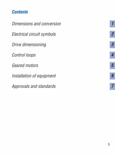
Contents
Dimensions and conversion
Electrical circuit symbols
Drive dimensioning
Control loops
Geared motors
Installation of equipment
Approvals and standards
1
2
3
4
5
6
7

6

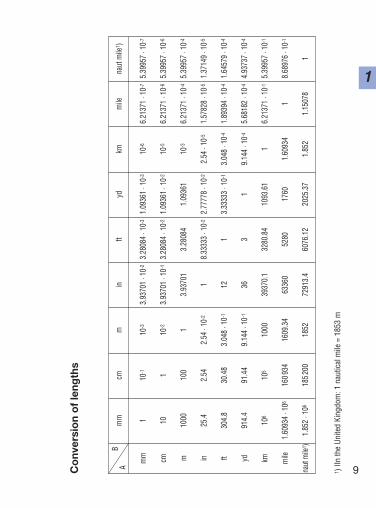
Dimensions and conversion
7
1
8
1
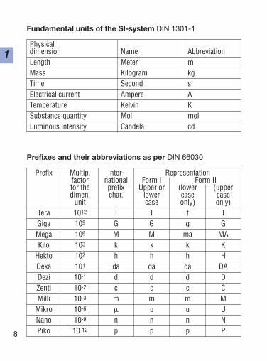
Fundamental units of the SI-system DIN 1301-1
Physical dimension Name AbbreviationLength Meter mMass Kilogram kgTime Second sElectrical current Ampere ATemperature Kelvin KSubstance quantity Mol molLuminous intensity Candela cd
Prefixes and their abbreviations as per DIN 66030
Prefix Multip. Inter- Representationfactor national Form I Form IIfor the prefix Upper or (lower (upperdimen. char. lower case case
unit case only) only)Tera 1012 T T t TGiga 109 G G g GMega 106 M M ma MAKilo 103 k k k K
Hekto 102 h h h HDeka 101 da da da DADezi 10-1 d d d DZenti 10-2 c c c CMilli 10-3 m m m M
Mikro 10-6 u u UNano 10-9 n n n NPiko 10-12 p p p P
Bm
mcm
min
ftyd
kmm
ilena
ut m
ile1 )
A
mm
110
-110
-33.
9370
1 · 1
0-2
3.28
084
· 10-
31.
0936
1 · 1
0-3
10-6
6.21
371
· 10-
75.
3995
7 · 1
0-7
cm10
110
-23.
9370
1 · 1
0-1
3.28
084
· 10-
21.
0936
1 · 1
0-2
10-5
6.21
371
· 10-
65.
3995
7 · 1
0-6
m10
0010
01
3.93
701
3.28
084
1.09
361
10-3
6.21
371
· 10-
45.
3995
7 · 1
0-4
in25
.42.
542.
54 ·
10-2
18.
3333
3 · 1
0-2
2.77
778
· 10-
22.
54 ·
10-5
1.57
828
· 10-
51.
3714
9 · 1
0-5
ft30
4.8
30.4
83.
048
· 10-
112
13.
3333
3 · 1
0-1
3.04
8 · 1
0-4
1.89
394
· 10-
41.
6457
9 · 1
0-4
yd91
4.4
91.4
49.
144
· 10-
136
31
9.14
4 · 1
0-4
5.68
182
· 10-
44.
9373
7 · 1
0-4
km10
610
510
0039
370.
132
80.8
410
93.6
11
6.21
371
· 10-
15.
3995
7 · 1
0-1
mile
1.60
934
· 106
1609
3416
09.3
463
360
5280
1760
1.60
934
18.
6897
6 · 1
0-1
naut
mile
1 )1.
852
· 106
1852
0018
5272
913.
460
76.1
220
25.3
71.
852
1.15
078
1
9
1C
onv
ersi
on
of
leng
ths
1 ) II
n th
e Un
ited
King
dom
: 1 n
autic
al m
ile =
185
3 m
10
1B
cm2
m2
aha
km2
in2ft2
yd2
sqac
reA
mile
cm2
110
-410
-610
-810
-10
1.55
000
· 10-1
1.07
639
· 10-3
1.19
599
· 10-4
3.86
102
· 10-1
12.
4710
5 · 1
0-8
m2
1000
01
10-2
10-4
10-6
1550
.00
10.7
639
1.19
599
3.86
102
· 10-7
2.47
105
· 10-4
a10
610
01
10-2
10-4
1550
0010
76.3
911
9.59
93.
8610
2 · 1
0-52.
4710
5 · 1
0-2
ha10
810
000
100
110
-21.
5500
0 · 1
0710
7639
1195
9.9
3.86
102
· 10-3
2.47
105
km2
1010
106
1000
010
01
1.55
000
· 109
1.07
639
· 107
1.19
599
· 106
3.86
102
· 10-1
247.
105
in26.
4516
06.
4516
0 · 1
0-46.
4516
0 · 1
0-66.
4516
0 · 1
0-86.
4516
0 · 1
0-10
16.
9444
4 · 1
0-37.
7160
5 · 1
0-42.
4909
8 · 1
0-10
1.59
423
· 10-7
ft292
9.03
09.
2903
0 · 1
0-29.
2903
0 · 1
0-49.
2903
0 · 1
0-69.
2903
0 · 1
0-814
41
1.11
111
· 10-1
3.58
701
· 10-8
2.29
568
· 10-5
yd2
8361
.27
8.36
127
· 10-1
8.36
127
· 10-3
8.36
127
· 10-5
8.36
127
· 10-7
1296
91
3.22
831
· 10-7
2.06
612
· 10-4
sq m
ile2.
5899
9 · 1
010
2.58
999
· 106
2589
9.9
258.
999
2.58
999
4.01
449
· 109
2.78
784
· 107
3.09
760
· 106
164
0
acre
4.04
686
· 107
4046
.86
40.4
686
4.04
686
· 10-1
4.04
686
· 10-3
6.27
264
· 106
4356
0.0
4840
1.56
250
· 10-3
1
Co
nver
sio
n o
f ar
eas
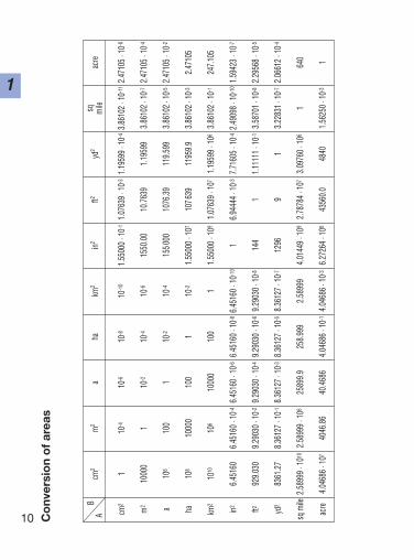
11
1C
onv
ersi
on
of
volu
mes
Bcm
3dm
3= I
in3ft3
yd3
US fl
ozIm
p fl o
zUS
gal
Imp g
alIm
p pint
A cm3
110
-36.1
0237
· 10-2
3.531
47 · 1
0-51.3
0795
· 10-6
3.381
40 · 1
0-23.5
1951
· 10-2
2.641
72 · 1
0-42.1
9969
· 10-4
1.759
75 · 1
0-3
dm3
= I10
001
61.02
373.5
3147
· 10-2
1.307
95 · 1
0-333
.8140
35.19
512.6
4172
· 10-1
2.199
69 · 1
0-11.7
5975
in316
.3871
1.638
71 · 1
0-21
5.787
04 · 1
0-42.1
4335
· 10-5
5.541
13 · 1
0-15.7
6744
· 10-1
4.329
00 · 1
0-33.6
0465
· 10-3
2.883
72 · 1
0-2
ft328
316.8
28.31
6817
281
3.703
70 · 1
0-295
7.506
996.6
147.4
8052
6.228
8449
.8307
yd3
7645
5576
4.555
4665
627
125
852.7
2690
8.620
1.974
168.1
7913
45.43
US fl
oz29
.5735
2.957
35 · 1
0-21.8
0469
1.044
38 · 1
0-33.8
6807
· 10-5
11.0
4084
7.812
5 · 10
-36.5
0527
· 10-3
5.204
21 · 1
0-2
Imp f
l oz
28.41
312.8
4131
· 10-2
1.733
871.0
0340
· 10-3
3.716
29 · 1
0-59.6
0760
· 10-1
17.5
0594
· 10-3
6.25 ·
10-3
5 · 10
-2
US ga
l37
85.41
3.785
4123
11.3
3681
· 10-1
4.951
13 · 1
0-312
813
3.228
18.3
2674
· 10-1
6.661
39
Imp g
al45
46.09
4.546
0927
7.419
1.605
44 · 1
0-15.9
4606
· 10-3
153.7
2216
01.2
0095
18
Imp p
int56
8.261
5.682
61 · 1
0-134
.6774
2.006
80 · 1
0-27.4
3258
· 10-4
19.21
5220
1.501
19 · 1
0-11.2
5 · 10
-11
12
1
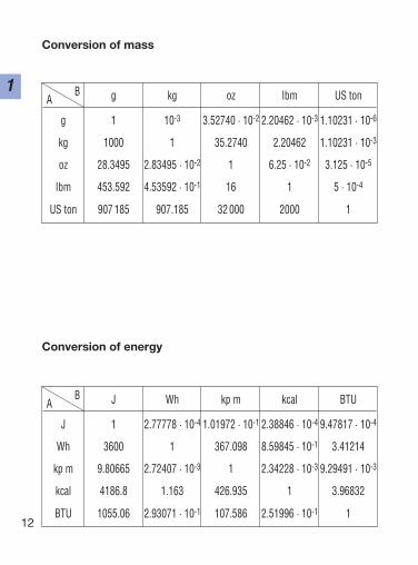
Conversion of mass
B g kg oz Ibm US tonA
g 1 10-3 3.52740 · 10-2 2.20462 · 10-3 1.10231 · 10-6
kg 1000 1 35.2740 2.20462 1.10231 · 10-3
oz 28.3495 2.83495 · 10-2 1 6.25 · 10-2 3.125 · 10-5
Ibm 453.592 4.53592 · 10-1 16 1 5 · 10-4
US ton 907 185 907.185 32 000 2000 1
B J Wh kp m kcal BTUA
J 1 2.77778 · 10-4 1.01972 · 10-1 2.38846 · 10-4 9.47817 · 10-4
Wh 3600 1 367.098 8.59845 · 10-1 3.41214
kp m 9.80665 2.72407 · 10-3 1 2.34228 · 10-3 9.29491 · 10-3
kcal 4186.8 1.163 426.935 1 3.96832
BTU 1055.06 2.93071 · 10-1 107.586 2.51996 · 10-1 1
Conversion of energy
13
1
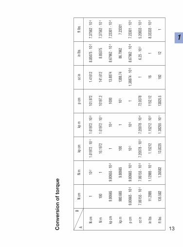
Co
nver
sio
n o
f to
rque
BN
cmN
mkp
cmkp
mp
cmoz
inin
lbsft
lbsA
N cm
110
-21.
0197
2 · 1
0-11.
0197
2 · 1
0-310
1.97
21.
4161
28.
8507
5 · 1
0-27.
3756
2 · 1
0-3
N m
100
110
.197
21.
0197
2 · 1
0-110
197.
214
1.61
28.
8507
57.
3756
2 · 1
0-1
kp cm
9.80
665
9.80
655
· 10-2
110
-210
0013
.887
48.
6796
2 · 1
0-17.
2330
1 · 1
0-2
kp m
980.
665
9.80
665
100
110
513
88.7
486
.796
27.
2330
1
p cm
9.80
665
· 10-3
9.80
665
· 10-5
10-3
10-5
11.
3887
4 · 1
0-28.
6796
2 · 1
0-47.
2330
1 · 1
0-5
oz in
7.06
155
· 10-1
7.06
155
· 10-3
7.20
078
· 10-2
7.20
078
· 10-4
72.0
078
16.
25 ·
10-2
5.20
833
· 10-3
in lbs
11.2
985
1.12
985
· 10-1
1.15
212
1.15
212
· 10-2
1152
.12
161
8.33
333
· 10-2
ft lbs
135.
582
1.35
582
13.8
225
1.38
255
· 10-1
1382
5.5
192
121
14
1B
kg cm
2kp
cm s2
kg m
2kp
m s2
oz in
2oz
in s2
Lb in
2Lb
in s2
Lb ft
2Lb
ft s2
A kg cm
21
1.01
972
· 10-3
10-4
1.01
972
· 10-5
5.46
748
1.41
612
· 10-2
3.41
717
· 10-1
8.85
075
· 10-4
2.37
304
· 10-3
7.37
562
· 10-5
kp cm
s298
0.66
51
9.80
655
· 10-2
10-2
5361
.76
13.8
874
335.
110
8.67
962
· 10-1
2.32
715
7.23
301
· 10-2
kg m
210
410
.197
21
1.01
972
· 10-1
5467
4.8
141.
612
3417
.17
8.85
075
23.7
304
7.37
562
· 10-1
kp m
s298
066.
510
09.
8066
51
5361
7613
88.7
433
511.
086
.796
223
2.71
57.
2330
1
oz in
21.
8290
0 · 1
0-11.
8650
6 · 1
0-41.
8290
0 · 1
0-51.
8650
6 · 1
0-61
2.59
008
· 10-3
6.25
· 10
-21.
6188
0 · 1
0-44.
3402
8 · 1
0-41.
3490
0 · 1
0-5
oz in
s270
.615
57.
2007
8 · 1
0-27.
0615
5 · 1
0-37.
2007
8 · 1
0-438
6.08
91
24.1
305
6.25
· 10
-21.
6757
3 · 1
0-15.
2083
3 · 1
0-3
Lb in
22.
9264
02.
9840
9 · 1
0-32.
9264
0 · 1
0-42.
9840
9 · 1
0-516
4.14
413
· 10-2
12.
5900
8 · 1
0-36.
9444
4 · 1
0-32.
1584
0 · 1
0-4
Lb in
s211
29.8
51.
1521
21.
1298
5 · 1
0-11.
1521
2 · 1
0-261
77.4
216
386.
089
12.
6811
78.
3333
3 · 1
0-2
Lb ft
242
1.40
14.
2971
0 · 1
0-14.
2140
1 · 1
0-24.
2971
0 · 1
0-323
04.0
05.
9675
414
43.
7297
1 · 1
0-11
3.10
810
· 10-2
Lb ft
s213
558.
213
.825
51.
3558
21.
3825
5 · 1
0-174
129.
019
246
33.0
612
32.1
740
1
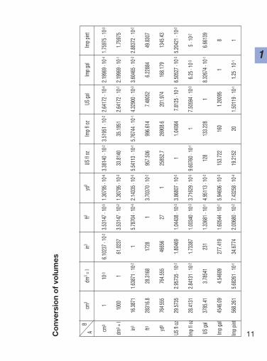
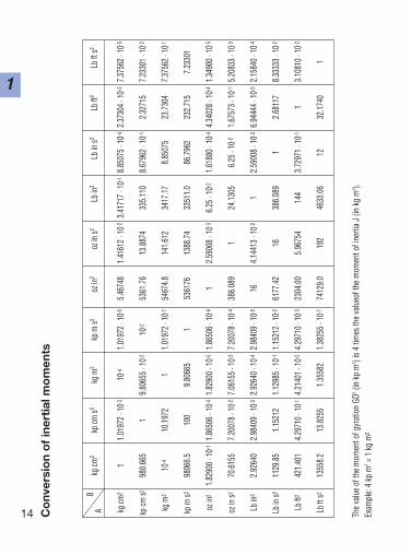
Co
nver
sio
n o
f in
erti
al m
om
ents
The
valu
e of
the
mom
ent o
f gyr
atio
n GD
2(in
kp
m2 ) i
s 4
times
the
valu
eof t
he m
omen
t of i
nerti
aJ
(in k
g m
2 ).Ex
ampl
e: 4
kp
m2=
1 kg
m2
15
1
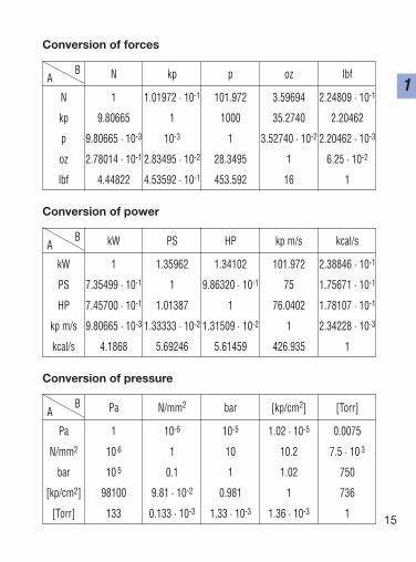
Conversion of forces
B N kp p oz lbfA
N 1 1.01972 · 10-1 101.972 3.59694 2.24809 · 10-1
kp 9.80665 1 1000 35.2740 2.20462
p 9.80665 · 10-3 10-3 1 3.52740 · 10-2 2.20462 · 10-3
oz 2.78014 · 10-1 2.83495 · 10-2 28.3495 1 6.25 · 10-2
lbf 4.44822 4.53592 · 10-1 453.592 16 1
B Pa N/mm2 bar [kp/cm2] [Torr]A
Pa 1 10-6 10-5 1.02 · 10-5 0.0075
N/mm2 10 6 1 10 10.2 7.5 · 10 3
bar 10 5 0.1 1 1.02 750
[kp/cm2] 98100 9.81 · 10-2 0.981 1 736
[Torr] 133 0.133 · 10-3 1.33 · 10-3 1.36 · 10-3 1
Conversion of pressure
B kW PS HP kp m/s kcal/sA
kW 1 1.35962 1.34102 101.972 2.38846 · 10-1
PS 7.35499 · 10-1 1 9.86320 · 10-1 75 1.75671 · 10-1
HP 7.45700 · 10-1 1.01387 1 76.0402 1.78107 · 10-1
kp m/s 9.80665 · 10-3 1.33333 · 10-2 1.31509 · 10-2 1 2.34228 · 10-3
kcal/s 4.1868 5.69246 5.61459 426.935 1
Conversion of power
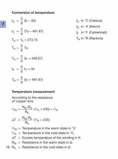
Conversion of temperature
tC =5
(tF – 32)9
tC =5
(TR – 491.67)9
TK = tC + 273.15
TK =5
TR9
TK =5
(tF + 459.67)9
tF =5
tC + 329
TR =5
(tC + 491.67)9
Temperature measurement
According to the resistanceof copper wire
~W =RW-RK (~K + 235) + ~KRK
T =RW-RK (~K + 235)
RK
~W = Temperature in the warm state in °C~K = Temperature in the cold state in °CT = Excess temperature of the winding in KRW = Resistance in the warm state in ΩRK = Resistance in the cold state in Ω16
1tC in °C (Celsius)
tK in K (Kelvin)
tF in °F (Fahrenheit)
TR in °R (Rankine)
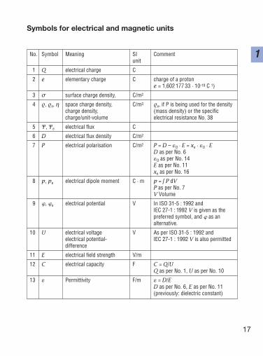
No. Symbol Meaning SI Commentunit
1 Q electrical charge C
2 e elementary charge C charge of a protone = 1,602 177 33 · 10-19 C 1)
3 σ surface charge density, C/m2
4 , e, η space charge density, C/m3 e, if P is being used for the density charge density, (mass density) or the specificcharge/unit-volume electrical resistance No. 38
5 Ψ, Ψe electrical flux C
6 D electrical flux density C/m2
7 P electrical polarisation C/m2 P = D – O · E = xe · O · ED as per No. 6O as per No. 14E as per No. 11xe as per No. 16
8 p, pe electrical dipole moment C · m p = ∫ P dVP as per No. 7V Volume
9 , e electrical potential V In ISO 31-5 : 1992 and IEC 27-1 : 1992 V is given as the preferred symbol, and as an alternative.
10 U electrical voltage V As per ISO 31-5 : 1992 andelectrical potential- IEC 27-1 : 1992 V is also permitteddifference
11 E electrical field strength V/m
12 C electrical capacity F C = Q/UQ as per No. 1, U as per No. 10
13 Permittivity F/m = D/ED as per No. 6, E as per No. 11(previously: dielectric constant)
17
1
Symbols for electrical and magnetic units
18
1
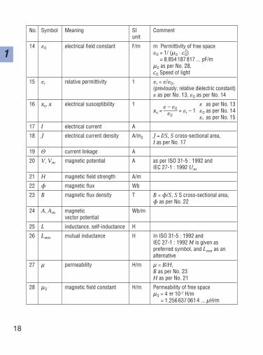
No. Symbol Meaning SI Commentunit
14 O electrical field constant F/m m Permittivity of free spaceO = 1/ (µO · cO
2)= 8.854 187 817 ... pF/m
µO as per No. 28, cO Speed of light
15 r relative permittivity 1 r = /O, (previously: relative dielectric constant) as per No. 13, O as per No. 14
16 xe, x electrical susceptibility 1 – O as per No. 13
xe = ––––– = r – 1 O as per No. 14O r as per No. 15
17 I electrical current A
18 J electrical current density A/m2 J = I/S, S cross-sectional area, I as per No. 17
19 Θ current linkage A
20 V, Vm magnetic potential A as per ISO 31-5 : 1992 andIEC 27-1 : 1992 Um
21 H magnetic field strength A/m
22 φ magnetic flux Wb
23 B magnetic flux density T B = φ/S, S S cross-sectional area, φ as per No. 22
24 A, Am magnetic Wb/mvector potential
25 L inductance, self-inductance H
26 Lmn mutual inductance H In ISO 31-5 : 1992 and IEC 27-1 : 1992 M is given as preferred symbol, and Lmn as analternative
27 µ permeability H/m µ = B/H, B as per No. 23H as per No. 21
28 µO magnetic field constant H/m Permeability of free spaceµO = 4 π 10-7 H/m
= 1.256 637 061 4 ... µH/m
19
1
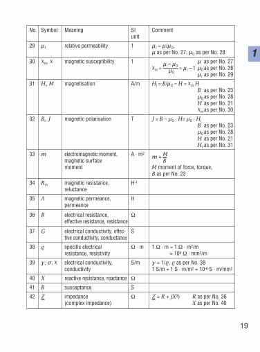
No. Symbol Meaning SI Commentunit
29 µr relative permeability 1 µr = µ/µO, µ as per No. 27, µO as per No. 28
30 m, magnetic susceptibility 1 µ – µO
µ as per No. 27
m = –––––– = µr – 1 µO as per No. 28µO µr as per No. 29
31 Hi, M magnetisation A/m Hi = B/µO – H = m HB as per No. 23µO as per No. 28H as per No. 21
m as per No. 30
32 Bi, J magnetic polarisation T J = B – µO · H= µO · HiB as per No. 23µO as per No. 28H as per No. 21Hi as per No. 31
33 m electromagnetic moment, A · m2m = M
magnetic surface Bmoment M moment of force, torque,
B as per No. 23
34 Rm magnetic resistance, H-1
reluctance
35 Λ magnetic permeance, Hpermeance
36 R electrical resistance, Ωeffective resistance, resistance
37 G electrical conductivity, effec- Stive conductivity, conductance
38 specific electrical Ω · m 1 Ω · m = 1 Ω · m2/mresistance, resistivity = 106 Ω · mm2/m
39 γ, σ, electrical conductivity, S/m γ = 1/, as per No. 38conductivity 1 S/m = 1 S · m/m2 = 10-6 S · m/mm2
40 X reactive resistance, reactance Ω
41 B susceptance S
42 Z impedance Ω Z = R + jX2) R as per No. 36(complex impedance) X as per No. 40
20
1
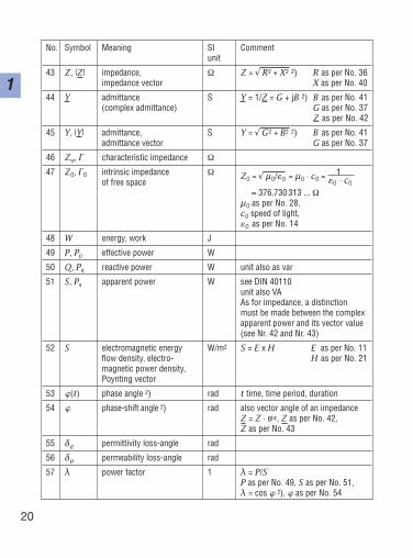
No. Symbol Meaning SI Commentunit
43 Z, |Z| impedance, Ω Z = √ R2 + X2 2) R as per No. 36impedance vector X as per No. 40
44 Y admittance S Y = 1/Z = G + jB 2) B as per No. 41(complex admittance) G as per No. 37
Z as per No. 42
45 Y, |Y| admittance, S Y = √ G2 + B2 2) B as per No. 41admittance vector G as per No. 37
46 Zw, Γ characteristic impedance Ω
47 ZO, ΓO intrinsic impedance Ω ZO = √ µO/O = µO · cO = 1of free space O · cO
≈ 376.730 313 ... ΩµO as per No. 28, cO speed of light, O as per No. 14
48 W energy, work J
49 P, Pp effective power W
50 Q, Pq reactive power W unit also as var
51 S, Ps apparent power W see DIN 40110unit also VAAs for impedance, a distinction must be made between the complexapparent power and its vector value(see Nr. 42 and Nr. 43)
52 S electromagnetic energy W/m2 S = E x H E as per No. 11flow density, electro- H as per No. 21magnetic power density,Poynting vector
53 (t) phase angle 2) rad t time, time period, duration
54 phase-shift angle 2) rad also vector angle of an impedanceZ = Z · ej, Z as per No. 42,Z as per No. 43
55 δ permittivity loss-angle rad
56 δµ permeability loss-angle rad
57 λ power factor 1 λ = P/SP as per No. 49, S as per No. 51,λ = cos 2), as per No. 54
21
1
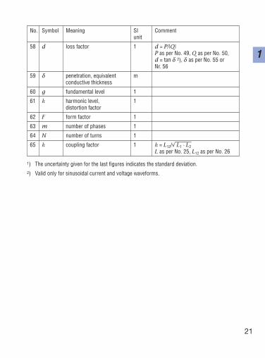
No. Symbol Meaning SI Commentunit
58 d loss factor 1 d = P/|Q|P as per No. 49, Q as per No. 50,d = tan δ 2), δ as per No. 55 or Nr. 56
59 δ penetration, equivalent mconductive thickness
60 g fundamental level 1
61 k harmonic level, 1distortion factor
62 F form factor 1
63 m number of phases 1
64 N number of turns 1
65 k coupling factor 1 k = L12/√ L1 · L2L as per No. 25, L12 as per No. 26
1) The uncertainty given for the last figures indicates the standard deviation.2) Valid only for sinusoidal current and voltage waveforms.

22
1
Electrical circuit symbols
23
2
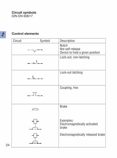
Circuit symbolsDIN EN 60617
Control elements
24
2Circuit Symbol Description
NotchNot self-releaseDevice to hold a given positionLock-out, non-latching
Lock-out latching
Coupling, free
Brake
Examples:Electromagnetically activatedbrake
Electromagnetically released brake
25
2
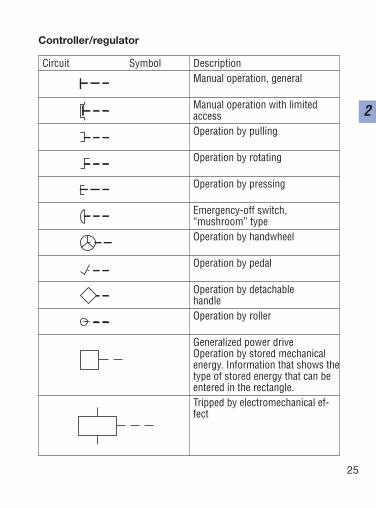
Circuit Symbol DescriptionManual operation, general
Manual operation with limitedaccessOperation by pulling
Operation by rotating
Operation by pressing
Emergency-off switch, “mushroom” typeOperation by handwheel
Operation by pedal
Operation by detachablehandleOperation by roller
Generalized power driveOperation by stored mechanicalenergy. Information that shows thetype of stored energy that can beentered in the rectangle.Tripped by electromechanical ef-fect
Controller/regulator
26
2
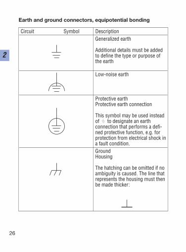
Circuit Symbol DescriptionGeneralized earth
Additional details must be addedto define the type or purpose ofthe earth
Low-noise earth
Protective earthProtective earth connection
This symbol may be used insteadof to designate an earth connection that performs a defi-ned protective function, e.g. forprotection from electrical shock ina fault condition.GroundHousing
The hatching can be omitted if noambiguity is caused. The line thatrepresents the housing must thenbe made thicker:
Earth and ground connectors, equipotential bonding
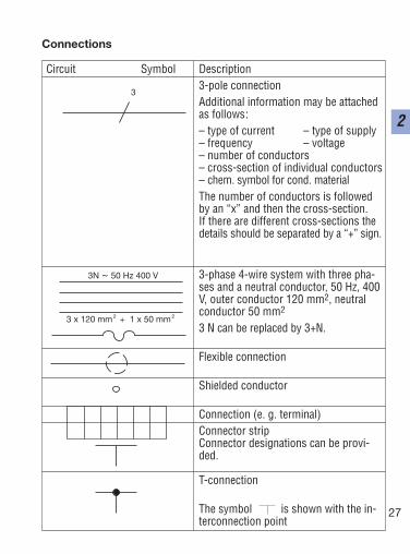
Connections
27
2
Circuit Symbol Description3-pole connectionAdditional information may be attachedas follows:– type of current – type of supply– frequency – voltage– number of conductors– cross-section of individual conductors– chem. symbol for cond. materialThe number of conductors is followedby an “x” and then the cross-section.If there are different cross-sections thedetails should be separated by a “+” sign.
3-phase 4-wire system with three pha-ses and a neutral conductor, 50 Hz, 400V, outer conductor 120 mm2, neutralconductor 50 mm2
3 N can be replaced by 3+N.
Flexible connection
Shielded conductor
Connection (e. g. terminal)Connector stripConnector designations can be provi-ded.
T-connection
The symbol is shown with the in-terconnection point
3
3 x 120 mm + 1 x 50 mm2 2
3N ~ 50 Hz 400 V
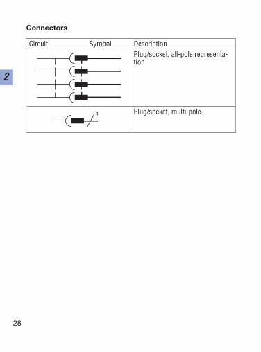
Connectors
28
2
Circuit Symbol DescriptionPlug/socket, all-pole representa-tion
Plug/socket, multi-pole4
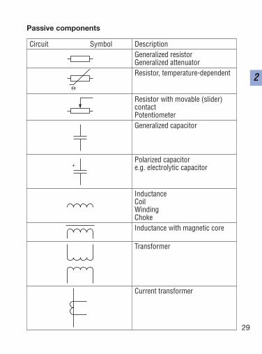
Passive components
29
2
Circuit Symbol DescriptionGeneralized resistorGeneralized attenuatorResistor, temperature-dependent
Resistor with movable (slider) contactPotentiometerGeneralized capacitor
Polarized capacitor e.g. electrolytic capacitor
InductanceCoilWindingChokeInductance with magnetic core
Transformer
Current transformer
+
30
2
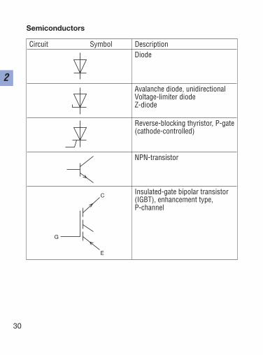
Semiconductors
Circuit Symbol DescriptionDiode
Avalanche diode, unidirectionalVoltage-limiter diodeZ-diode
Reverse-blocking thyristor, P-gate (cathode-controlled)
NPN-transistor
Insulated-gate bipolar transistor(IGBT), enhancement type, P-channel
G
C
E
31
2
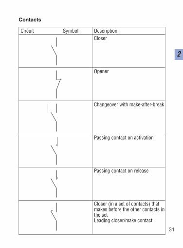
Contacts
Circuit Symbol DescriptionCloser
Opener
Changeover with make-after-break
Passing contact on activation
Passing contact on release
Closer (in a set of contacts) thatmakes before the other contacts inthe setLeading closer/make contact
32
2
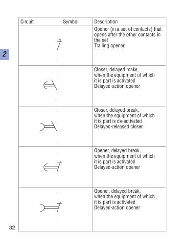
Circuit Symbol DescriptionOpener (in a set of contacts) thatopens after the other contacts inthe setTrailing opener
Closer, delayed make, when the equipment of which it is part is activatedDelayed-action opener
Closer, delayed break, when the equipment of which it is part is de-activatedDelayed-released closer
Opener, delayed break, when the equipment of which it is part is activatedDelayed-action opener
Opener, delayed break, when the equipment of which it is part is activatedDelayed-action opener
33
2
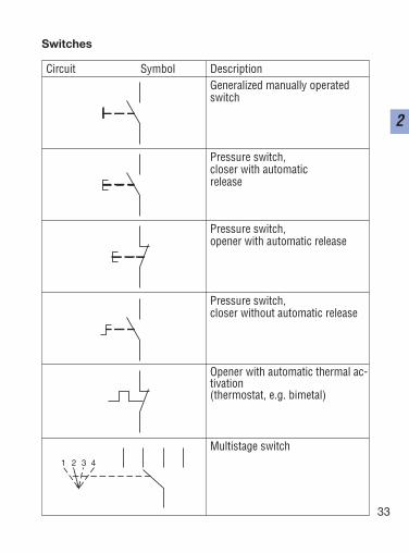
Switches
Circuit Symbol DescriptionGeneralized manually operatedswitch
Pressure switch,closer with automatic release
Pressure switch,opener with automatic release
Pressure switch,closer without automatic release
Opener with automatic thermal ac-tivation (thermostat, e.g. bimetal)
Multistage switch1 2 3 4
34
2
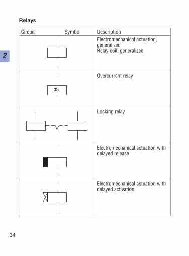
Relays
Circuit Symbol DescriptionElectromechanical actuation, generalizedRelay coil, generalized
Overcurrent relay
Locking relay
Electromechanical actuation withdelayed release
Electromechanical actuation withdelayed activation
I >
35
2
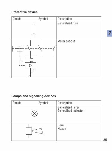
Protective device
Circuit Symbol DescriptionGeneralized fuse
Motor cut-out
I >
3
Lamps and signalling devices
Circuit Symbol DescriptionGeneralized lampGeneralized indicator
HornKlaxon
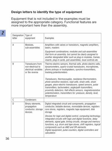
Design letters to identify the type of equipment
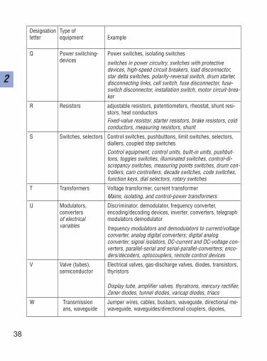
Equipment that is not included in the examples must beassigned to the appropriate category. Functional features aremore important here than the assembly.
36
2Designation Type of letter equipment Examples
A Modules, Amplifiers with valves or transistors, magnetic amplifiers,sub-assemblies lasers, masters
Equipment combinations; modules and sub-assemblies that form an assembly, but cannot be clearly assigned to another designated letter such as plug-in modules, frames,inserts, plug-in cards, pcb assemblies, local controls etc.
B Transducers from Thermo-electric sensors, thermal cells, photo-electric cells, non-electrical to dynamometers, quartz-crystal transducers, microphones,electrical variables phono pickups or loudspeakers, synchro-transmitters, or the reverse tracking potentiometers
Transducers, thermocouples, resistance thermometers,photo-sensitive resistors, load cells, strain cells, straingauges, piezo-electric transducers, speed sensors, pulsetransmitters, tachometers, angle/path transmitters,proximity detectors, Hall effects sensors, magnetoresistivepotentiometers, transmitters for: pressure, density, level,temperature
C Condensers
D Binary elements, Digital integrated circuit and components, propagationpropagation conductor, bistable devices, monostable devices, registersconductor, storage core stores, registers, magnetic tape equipment, diskdevices storage
Devices for logic and digital control, computing technology.Integrated circuits with logic and digital functions, delayelements, signal gate, timing circuits, storage and memoryfunctions, e.g. drum and tape stores, shift registers, logicalcomponents such as AND and OR elements. Digital equipment, pulse counters, digital controllers andcalculators
37
2
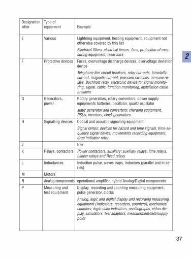
Designation Type ofletter equipment Example
E Various Lightning equipment, heating equipment, equipment nototherwise covered by this list
Electrical filters, electrical fences, fans, protection of mea-suring equipment, reservoirs
F Protective devices Fuses, overvoltage discharge devices, overvoltage deviationdevice
Telephone line circuit breakers, relay cut-outs, bimetalliccut-out, magnetic cut-out, pressure switches, air-vane re-lays, Buchholz relay, electronic device for signal monito-ring, signal, cable, function monitoring; installation cablebreakers
G Generators, Rotary generators, rotary converters, power supplypower equipments batteries, oscillator, quartz oscillator
static generator and converters; charging equipment,PSUs, inverters, clock generators
H Signalling devices Optical and acoustic signalling equipment
Signal lamps; devices for hazard and time signals, time-se-quence signal device, movements recording equipment,drop indicator relay
J free
K Relays, contactors Power contactors, auxiliary; auxiliary relays, time relays, blinker relays and Reed relays
L Inductances Induction pulse, waves traps, inductors (parallel and in se-ries)
M Motors
N Analog components operational amplifier, hybrid Analog/Digital components
P Measuring and Display, recording and counting measuring equipment,test equipment pulse generator, clocks
Analog, logic and digital display and recording measuringequipment (Indicators, recorders, counters), mechanicalcounters, logic-state indicators, oscillographs, video dis-play, simulators, test adaptors, measurement/test/supplypoint
38
2
Designation Type ofletter equipment Example
Q Power switching- Power switches, isolating switchesdevices switches in power circuitry, switches with protective
devices, high-speed circuit breakers, load disconnector,star delta switches, polarity-reversal switch, drum starter,disconnecting links, cell switch, fuse disconnector, fuse-switch disconnector, installation switch, motor circuit-brea-ker
R Resistors adjustable resistors, potentiometers, rheostat, shunt resi-stors, heat conductorsFixed-value resistor, starter resistors, brake resistors, coldconductors, measuring resistors, shunt
S Switches, selectors Control switches, pushbuttons, limit switches, selectors,diallers, coupled step switchesControl equipment, control units, built-in units, pushbut-tons, toggles switches, illuminated switches, control-di-screpancy switches, measuring points switches, drum con-trollers, cam controllers, decade switches, code switches,function keys, dial selectors, rotary switches
T Transformers Voltage transformer, current transformerMains, isolating, and control-power transformers
U Modulators, Discriminator, demodulator, frequency converter, converters encoding/decoding devices, inverter, converters, telegraphof electrical modulators demodulatorvariables frequency modulators and demodulators to current/voltage
converter, analog digital converters; digital analogconverter, signal isolators, DC-current and DC-voltage con-verters, parallel-serial and serial-parallel-converters; enco-ders/decoders, optocouplers, remote control devices
V Valve (tubes), Electrical valves, gas-discharge valves, diodes, transistors,semiconductor thyristors
Display tube, amplifier valves, thyratrons, mercury rectifier,Zener diodes, tunnel diodes, varicap diodes, triacs
W Transmission Jumper wires, cables, busbars, waveguide, directional me-ans, waveguide waveguide, waveguides/directional couplers, dipoles,
39
2
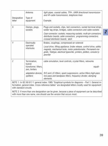
Antenna light pipes, coaxial cables, TFH-, UKW directional transmission and HF-cable transmission, telephone lines
Designation Type ofletter equipment Example
X Clamps, plugs, Plugs and sockets, clips, test connectors, socket terminal strips,sockets solder tag strips, bridges, cable connectors and cable sockets
Coax-connector; sockets; measuring sockets; multi-pin connectors;distributor boards; cable connectors; programming connectors;crossed distributor boards; latch
Y Electrically Brakes, couplings, compressed-air solenoidoperated Local drive, lifting appliance; brake release, control drive, safety interlocks magnets, mechanical locks, motor potentiometer, Permanent-ma-
gnets, Teletype, electrical typewriter, printers, plotters, console ty-pewriter
Z Termination, cable simulation, level controls, crystal filters, networkshybrid transfomer, filters, equali-zers, limiters
adaptation devices, R/C and L/C-filters, spark suppressors, active filters,high-passsplitters low-pass and bandpass filters, frequency divider, damping
elements
NOTE 1: In IEC 60 617-1 general index: 1985 “Graphical symbols for diagrams – Part 1: General in-formation, general index. Cross-reference tables” are designated letters mostly used for equipmentwith standard circuits
NOTE 2: If more than one designation can be given, because a piece of equipment can be describedwith more than one name, one should use the version that occurs most.
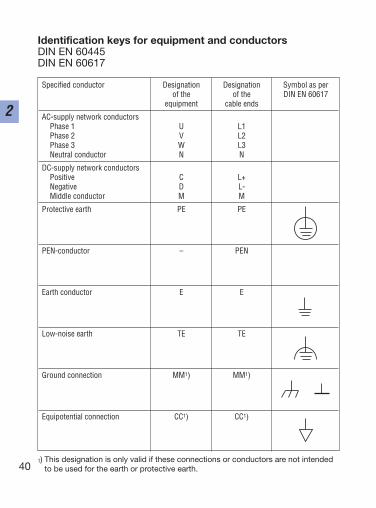
Identification keys for equipment and conductorsDIN EN 60445DIN EN 60617
40
2
1) This designation is only valid if these connections or conductors are not intendedto be used for the earth or protective earth.
Specified conductor Designation Designation Symbol as perof the of the DIN EN 60617
equipment cable ends
AC-supply network conductorsPhase 1 U L1Phase 2 V L2Phase 3 W L3Neutral conductor N N
DC-supply network conductorsPositive C L+Negative D L-Middle conductor M M
Protective earth PE PE
PEN-conductor – PEN
Earth conductor E E
Low-noise earth TE TE
Ground connection MM1) MM1)
Equipotential connection CC1) CC1)
41
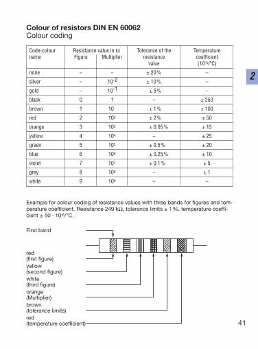
2
Example for colour coding of resistance values with three bands for figures and tem-perature coefficient. Resistance 249 kΩ, tolerance limits ± 1%, temperature coeffi-cient ± 50 · 10-6/°C.
First band
red(first figure)yellow(second figure)white(third figure)orange(Multiplier)brown(tolerance limits)red(temperature coefficient)
Colour of resistors DIN EN 60062Colour coding
Code-colour Resistance value in Ω Tolerance of the Temperaturename Figure Multiplier resistance coefficient
value (10-6/°C)
none – – ± 20% –
silver – 10-2 ± 10% –
gold – 10-1 ± 5% –
black 0 11 – ± 250
brown 1 101 ± 1% ± 100
red 2 102 ± 2% ± 50
orange 3 103 ± 0.05% ± 15
yellow 4 104 – ± 25
green 5 105 ± 0.5% ± 20
blue 6 106 ± 0.25% ± 10
violet 7 107 ± 0.1% ± 5
grey 8 108 – ± 1
white 9 109 – – 101

42
2
Drive dimensioning
43
3
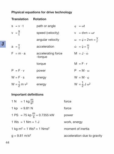
Physical equations for drive technology
Translation Rotation
s = v · t path or angle = t
v = s speed (velocity) v = dn = rt
angular velocity = = 2n = vr
a = v acceleration = = t t
F = m · a accelerating force M = J · -torque
torque M = F · r
P = F · v power P = M ·
W = F · s energy W = M ·
W = 1 m v2 energy W = 1 J 22 2
Important definitions
1 N = 1 kg m forces2
1 kp = 9.81 N force
1 PS = 75 kp m = 0.7355 kW powers
1 Ws = 1 Nm = 1 J work, energy
1 kg m2 = 1 Ws3 = 1 Nms2 moment of inertia
g = 9.81 m/s2 acceleration due to gravity
44
3
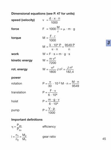
Dimensional equations (see P. 47 for units)
speed (velocity) v = d · · n1000
force F = 1000 M = · m · gr
torque M = F · r1000
M = 3 · 104 P = 9549 P · n n
work W = F · s = m · g · s
kinetic energy W = m v2
7200
rot. energy W = 2J n2 = J n2
1800 182,4
power
rotation P = · 10-3 M · n = M · n30 9549
translation P = F · v6 · 104
hoist P = m · g · v6 · 104
pump P = V · p1000
Important definitions
= Pab efficiencyPzu
i = n1 = M2 gear ration2 M1 45
3
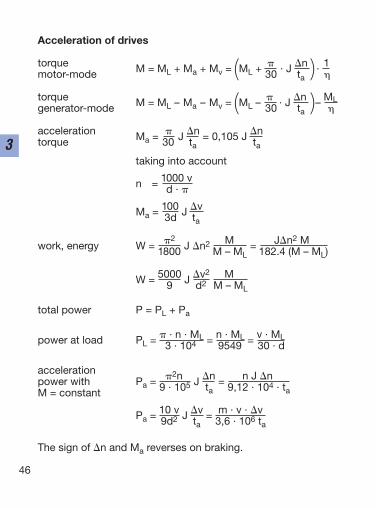
Acceleration of drives
torque M = ML + Ma + Mv = ML + · J n · 1motor-mode ( 30 ta )
torque M = ML – Ma – Mv = ML – · J n – MLgenerator-mode ( 30 ta )
acceleration Ma = J n = 0,105 J ntorque 30 ta ta
taking into account
n = 1000 vd ·
Ma = 100 J v3d ta
work, energy W = 2J n2 M = Jn2 M
1800 M – ML 182.4 (M – ML)
W = 5000 J v2 M9 d2 M – ML
total power P = PL + Pa
power at load PL = · n · ML = n · ML = v · ML3 · 104 9549 30 · d
accelerationpower with Pa = 2n J n = n J n
M = constant 9 · 105 ta 9,12 · 104 · ta
Pa = 10 v J v = m · v · v9d2 ta 3,6 · 106 ta
The sign of n and Ma reverses on braking.
46
3
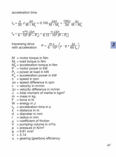
acceleration time
ta = J n = 0.105 Jn = 100J v30 M – ML M – ML 3d M – ML
ta = 2n Jn = n Jn9 · 105 (P – PL) 9.12 · 104 (P – PL)
traversing drive P = m v · g + v
with acceleration 6 · 104 ( 60 ta )
M = motor torque in NmML = load torque in NmMa = acceleration torque in NmP = motor power in kWPL = power at load in kWPa = acceleration power in kWn = speed in rpmn = speed difference in rpmv = velocity in m/minv = velocity difference in m/minJ = total moment of inertia in kgm2
m = mass in kgF = force in NW = energy in Jta = acceleration time in ss = distance in md = diameter in mmr = radius in mm = coefficient of frictionV = pumping volume in m3/sp = pressure in N/m2
g = 9.81 m/s2
= 3.14 = gearing (gearbox) efficiency
47
3
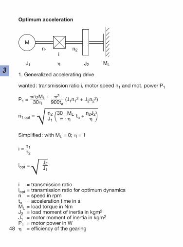
Optimum acceleration
1. Generalized accelerating drive
wanted: transmission ratio i, motor speed n1 and mot. power P1
P1 = n2ML + 2(J1n1
2 + J2n22)30 900ta
n1 opt = n2 30 · ML ta + n2J2J1 ( · )
Simplified: with ML = 0; = 1
i = n1 n2
iopt = J2J1
i = transmission ratioiopt = transmission ratio for optimum dynamicsn = speed in rpmta = acceleration time in sML = load torque in NmJ2 = load moment of inertia in kgm2
J1 = motor moment of inertia in kgm2
P1 = motor power in W = efficiency of the gearing48
3
M
J1
i
J2 ML
n1
n2
Optimum acceleration
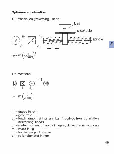
1.1. translation (traversing, linear)
J2 = m h 2(2000)
1.2. rotational
J2 = m d 2(2000)
n = speed in rpmi = gear ratioJ2 = load moment of inertia in kgm2, derived from translation
(traversing, linear)J1 = motor moment of inertia in kgm2, derived from rotationalm = mass in kgh = leadscrew pitch in mmd = roller diameter in mm
49
3M
m
load
slide/table
spindlen1 n2
J1 J2i h
+ +
m
J2iJ1
M d
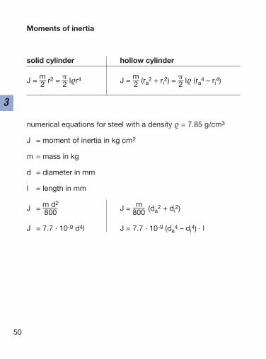
Moments of inertia
solid cylinder hollow cylinder
J = m r2 = lr4 J = m (ra2 + ri
2) = l (ra4 – ri
4)2 2 2 2
numerical equations for steel with a density = 7.85 g/cm3
J = moment of inertia in kg cm2
m = mass in kg
d = diameter in mm
l = length in mm
J = m d2J = m (da
2 + di2)800 800
J = 7.7 · 10-9 d4l J = 7.7 · 10-9 (da4 – di
4) · l
50
3
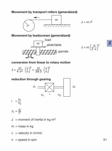
Movement by transport rollers (generalized)
J = m r2
Movement by leadscrews (generalized)
J = m h 2(2 )
conversion from linear to rotary motion
J = m v 2 = m v 24 2 (n) 39.5 (n)
reduction through gearing
i = n1n2
J1 = J2i2
J = moment of inertia in kg m2
m = mass in kg
v = velocity in m/min
n = speed in rpm 51
3
+
m
r
mload
slide/table
spindle
h
n2
J1 J2
n1i
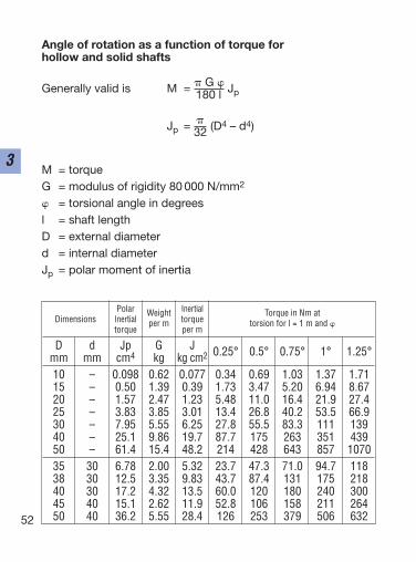
Angle of rotation as a function of torque for hollow and solid shafts
Generally valid is M = G Jp180 l
Jp = (D4 – d4)32
M = torqueG = modulus of rigidity 80 000 N/mm2
= torsional angle in degreesl = shaft lengthD = external diameterd = internal diameterJp = polar moment of inertia
52
3
Polar Weight Inertial Torque in Nm atDimensions Inertial per m torque torsion for l = 1 m and
torque per m
D d Jp G J 0.25° 0.5° 0.75° 1° 1.25°mm mm cm4 kg kg cm2
10 – 0.098 0.62 0.077 0.34 0.69 1.03 1.37 1.7115 – 0.50 1.39 0.39 1.73 3.47 5.20 6.94 8.6720 – 1.57 2.47 1.23 5.48 11.0 16.4 21.9 27.425 – 3.83 3.85 3.01 13.4 26.8 40.2 53.5 66.930 – 7.95 5.55 6.25 27.8 55.5 83.3 111 13940 – 25.1 9.86 19.7 87.7 175 263 351 43950 – 61.4 15.4 48.2 214 428 643 857 107035 30 6.78 2.00 5.32 23.7 47.3 71.0 94.7 11838 30 12.5 3.35 9.83 43.7 87.4 131 175 21840 30 17.2 4.32 13.5 60.0 120 180 240 30045 40 15.1 2.62 11.9 52.8 106 158 211 26450 40 36.2 5.55 28.4 126 253 379 506 632
53
3
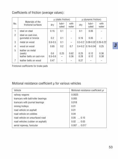
Coefficients of friction (average values):
Frictional coefficients for brake pads
Motional resistance coefficient µ for various vehicles
µ (static friction) µ (dynamic friction)
No.Materials of the
dry lubri- with dry lubri- withfrictional surfacescated water cated water
1 steel on steel 0.15 0.1 – 0.1 0.05 –
2 steel on cast-iron,gunmetal or bronze 0.2 0.1 – 0.16 0.05 –
3 metal on wood 0.6-0.5 0.1 – 0.5-0.2 0.08-0.02 0.26-0.22
4 wood on wood 0.65 0.2 0.7 0.4-0.2 0.16-0.04 0.25
5 leather on metal(seals) 0.6 0.25 0.62 0.25 0.12 0.36leather belts on cast-iron 0.5-0.6 – 0.36 0.28 0.12 0.38
7 leather belts on wood 0.47 – – 0.27 – –
Vehicle Motional resistance coefficient µr
railway wagons 0.0025tramcars with ball/roller bearings 0.005tramcars with journal bearings 0.018mining trolleys 0.01road vehicle on asphalt 0.01road vehicle on cobbles 0.04road vehicle on unsurfaced road 0.05 … 0.15road vehicles (rubber on asphalt) 0.02 … 0.03aerial ropeway, funicular 0.007 … 0.017
54
3
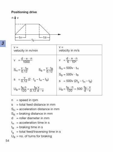
Positioning drive
n = speed in rpms = total feed distance in mmSH = acceleration distance in mmSB = braking distance in mmd = roller diameter in mmtH = acceleration time in stB = braking time in stg = total feed/traversing time in sUB = no. of turns for braking
tBtHtg
n v
v =velocity in m/min
v = d · · n1000
SH = v · tH SB = v · tB0.12 0.12
s = v (2 · tg – tH – tB)0.12
UB = tB n = tB v120 0.12 d ·
v =velocity in m/s
v = d · · n6 · 104
SH = 500v · tH
SB = 500v · tB
s = 500v (2tg – tH – tB)
UB = tB · n = 500 tB · v120 d ·

55
3
56
3
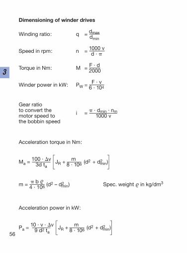
Dimensioning of winder drives
Winding ratio: q = dmaxdmin
Speed in rpm: n = 1000 vd ·
Torque in Nm: M = F · d2000
Winder power in kW: PW = F · v6 · 104
Gear ratioto convert the i = · dmin · nmmotor speed to 1000 vthe bobbin speed
Acceleration torque in Nm:
Ma = 100 · v JR + m (d2 + d2min)3d ta [ 8 · 106 ]
m = b (d2 – d2min) Spec. weight in kg/dm3
4 · 106
Acceleration power in kW:
Pa = 10 · v · v JR + m (d2 + d2min)9 d2 ta [ 8 · 106 ]
57
3
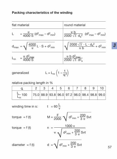
Packing characteristics of the winding
flat material round material
L = (d2max – d2
min) b (d2max – d2
min)4000 S 2000 √ 3 ds2
dmax = 4000 L · S + d2min
2000 √ 3 · L · ds2+ d2
min b
Lm = d2max b d2max4000 S 2000 √ 3 d2s
generalized L = Lm 1 – 1( q_2)relative packing length in %
winding time in s: t = 60 Lv
torque = f (t) M = F d2min + 200 Svt2000 3
torque = f (t) n = 1000 v
d2min + 200 Svt3
diameter = f (t) d = d2min + 200 Svt3
q_ 2 3 4 5 6 7 8 9 10L 100 75.0 88.9 93.8 96.0 97.2 98.0 98.4 98.8 99.0Lm .
58
3
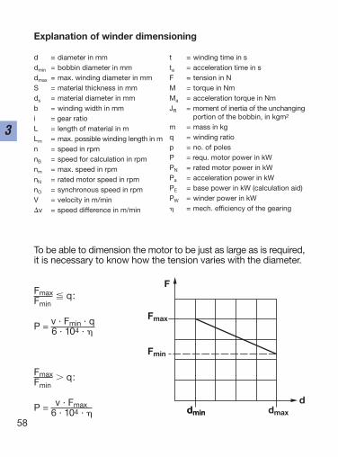
Explanation of winder dimensioning
d = diameter in mmdmin = bobbin diameter in mmdmax = max. winding diameter in mmS = material thickness in mmds = material diameter in mmb = winding width in mmi = gear ratioL = length of material in mLm = max. possible winding length in mn = speed in rpmnB = speed for calculation in rpmnm = max. speed in rpmnN = rated motor speed in rpmnO = synchronous speed in rpmV = velocity in m/minv = speed difference in m/min
t = winding time in sta = acceleration time in sF = tension in NM = torque in NmMa = acceleration torque in NmJR = moment of inertia of the unchanging
portion of the bobbin, in kgm2
m = mass in kgq = winding ratiop = no. of polesP = requ. motor power in kWPN = rated motor power in kWPa = acceleration power in kWPE = base power in kW (calculation aid)PW = winder power in kW = mech. efficiency of the gearing
To be able to dimension the motor to be just as large as is required,it is necessary to know how the tension varies with the diameter.
Fmax q:Fmin
P = v · Fmin · q6 · 104 ·
Fmax q:Fmin
P = v · Fmax6 · 104 ·
F
Fmax
Fmin
dmin dmaxdmin
d
59
3
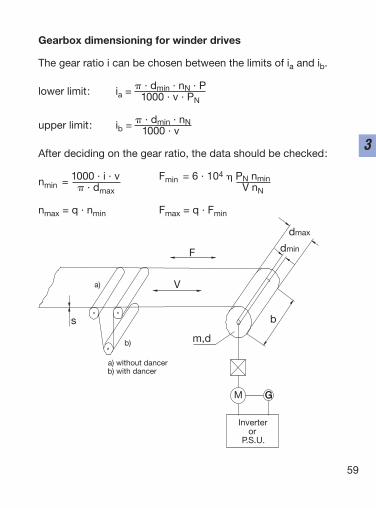
Gearbox dimensioning for winder drives
The gear ratio i can be chosen between the limits of ia and ib.
lower limit: ia = · dmin · nN · P1000 · v · PN
upper limit: ib = · dmin · nN1000 · v
After deciding on the gear ratio, the data should be checked:
nmin = 1000 · i · v Fmin = 6 · 104 PN nmin · dmax V nN
nmax = q · nmin Fmax = q · Fmin
b) with dancera) without dancer
m,d
P.S.U.or
Inverter
GGM
a)
b)
b
dmin
dmax
s
V
F

60
3
Control loops
61
4
62
4
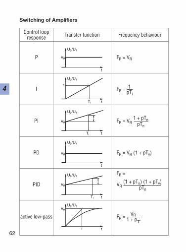
Switching of Amplifiers
Control loop Transfer function Frequency behaviourresponse
P FR = VR
I FR = 1pTi
PI FR = VR1 + pTn
pTn
PD FR = VR (1 + pTv)
FR =
PID VR(1 + pTn) (1 + pTv)
pTn
active low-pass FR = VR1 + pτ
U2/U1
VR
t
U2/U1
1
t
U2/U1
VR
t
U2/U1
VR
t
U2/U1
VR
t
U2/U1VR
t
Ti
Ti
1
Ti
1
τ
63
4
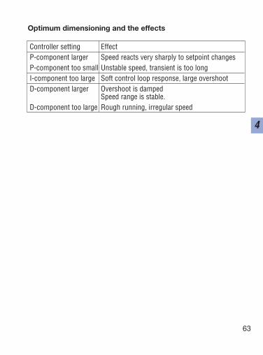
Optimum dimensioning and the effects
Controller setting EffectP-component larger Speed reacts very sharply to setpoint changesP-component too small Unstable speed, transient is too longI-component too large Soft control loop response, large overshootD-component larger Overshoot is damped
Speed range is stable.D-component too large Rough running, irregular speed
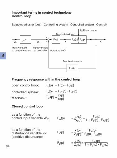
Important terms in control technologyControl loop
Frequency response within the control loop
open control loop: Fo(p) = Fr(p) · Fs(p)
controlled system: Fs(p) = Fs1(p) · Fs2(p)
feedback: Fs3(p) = xi(p)x (p)
Closed control loop
as a function of thecontrol input variable W2: Fw(p) = x (p) = Fo(p)
W2(p) 1 + Fo(p) · Fs3(p)
as a function of thedisturbance variable Zs: Fz(p) = x (p) = Fw(p)
(additive disturbance)Zs(p) Fr(p) · Fs1(p)
Fz(p) = x (p) = Fs2(p)Zs(p) 1 + Fo(p) · Fs3(p)64
4
Setpoint adjuster (pot.) Controlling system Controlled system Controlle
Feedback sensor
Actual value Xi
Manipulated var.
ZS Disturbance
XYW2 W1
Input variableto control system
+_ Fr(p) Fs1(p) Fs2(p)
Fs3(p)
Input variableto controller
65
4
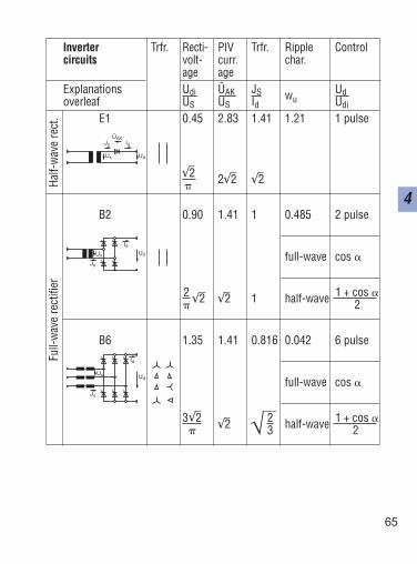
Inverter Trfr. Recti- PIV Trfr. Ripple Controlcircuits volt- curr. char.
age ageExplanations Udi ÛAK JS wu
Udoverleaf US US Id Udi
E1 0.45 2.83 1.41 1.21 1 pulse
√2 2√2 √2
B2 0.90 1.41 1 0.485 2 pulse
full-wave cos
2 √2 √2 1 half-wave 1 + cos 2
B6 1.35 1.41 0.816 0.042 6 pulse
full-wave cos
3√2 √2 2 half-wave 1 + cos 3 2
Full-
wav
e re
ctifi
erHa
lf-w
ave
rect
.
Js
ÛAKId
UdUs
Js
IdUdUs
Js
Id
UdUs
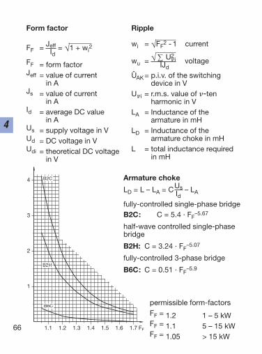
Form factor
FF = Jeff = √1 + wi2
IdFF = form factorJeff = value of current
in AJs = value of current
in AId = average DC value
in AUs = supply voltage in VUd = DC voltage in VUdi = theoretical DC voltage
in V
Ripple
wi = √FF2 - 1 current
wu = √ ∑ U2i voltageIJd
UAK= p.i.v. of the switching device in V
Ui = r.m.s. value of -tenharmonic in V
LA = Inductance of the armature in mH
LD = Inductance of the armature choke in mH
L = total inductance required in mH
66
4
1
2
3
4
1.1 1.2 1.3 1.4 1.5 1.6 1.7 FF
B2C
B2H
B6C
Armature choke
LD = L – LA = CUs – LAIdfully-controlled single-phase bridgeB2C: C = 5.4 · FF
–5.67
half-wave controlled single-phasebridge
B2H: C = 3.24 · FF–5.07
fully-controlled 3-phase bridge
B6C: C = 0.51 · FF–5.9
permissible form-factorsFF = 1.2 1 – 5 kWFF = 1.1 5 – 15 kWFF = 1.05 > 15 kW
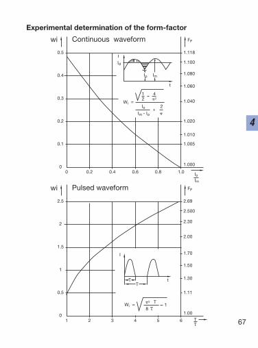
Experimental determination of the form-factor
67
4
0 0.2 0.4 0.6 0.8 1.00
0.1
0.2
0.3
0.4
0.5
1.000
1.005
1.020
1.010
1.040
1.080
1.118
1.100
1.060
FF
1 2 3 4 5 60
0.5
1
1.5
2
2.5
1.00
1.11
1.50
1.30
1.70
2.30
2.69
2.500
2.00
FF
wi Continuous waveform
wi Pulsed waveform
IId
Wi
Io Im
t
=
1 42 2
Io 2
Im - Io +
IoIm
I
Wi
Tt
= 2 T
T
18

68
4
Geared motors
69
5

Shaft angle Standard Gearratios efficiency
0 1 ... 6 Very good
Helical gear
90 1 ... 6 Very good
Bevel gear
i = 5: Good90 5 ... 60
i = 60: Poor
Worm gear
1 Typical toothed gear designs
70
5
Depending on the required shaft angle and ratio range, one ormore wheel sets are combined within the gear. The total ratio iscalculated by multiplying the individual ratios.
2 Standard materials for geared motors
Housing: Output torque < 100 Nm: Aluminium alloys, cast iron
Output torque > 100 Nm: Cast ironShafts: Tempering steels C45, C60, 42CrMo 4Gears: Case hardening steels 16MnCr5, 20MnCr5,
17CrNiMo6
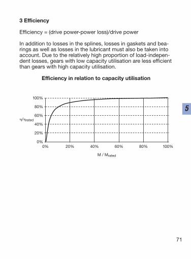
3 Efficiency
Efficiency = (drive power-power loss)/drive power
In addition to losses in the splines, losses in gaskets and bea-rings as well as losses in the lubricant must also be taken intoaccount. Due to the relatively high proportion of load-indepen-dent losses, gears with low capacity utilisation are less efficientthan gears with high capacity utilisation.
Efficiency in relation to capacity utilisation
71
5
0% 20% 40% 60% 80% 100%0%
20%
40%
60%
80%
100%
M / Mrated
/rated
4 Lubricants
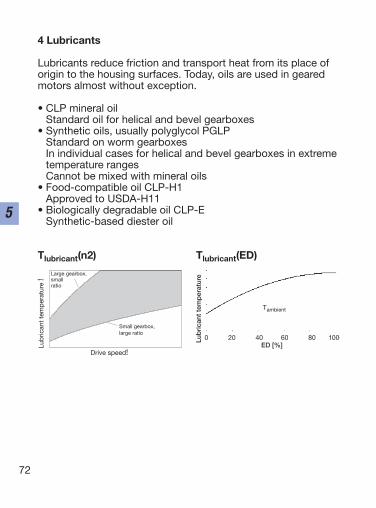
Lubricants reduce friction and transport heat from its place oforigin to the housing surfaces. Today, oils are used in gearedmotors almost without exception.
• CLP mineral oilStandard oil for helical and bevel gearboxes
• Synthetic oils, usually polyglycol PGLPStandard on worm gearboxesIn individual cases for helical and bevel gearboxes in extremetemperature rangesCannot be mixed with mineral oils
• Food-compatible oil CLP-H1Approved to USDA-H11
• Biologically degradable oil CLP-E Synthetic-based diester oil
72
5
kleines Getriebe,große Übersetzung
großes Getriebe,kleine Übersetzung
Tlubricant(n2) Tlubricant(ED)
Small gearbox,large ratio
Lub
rican
t te
mp
erat
ure
!
Lub
rica
nt t
emp
erat
ure
Drive speed!
Large gearbox,small ratio
Tambient
0 20 40 60 80 100ED [%]
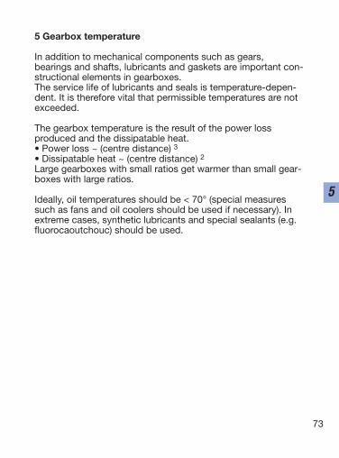
5 Gearbox temperature
In addition to mechanical components such as gears, bearings and shafts, lubricants and gaskets are important con-structional elements in gearboxes.The service life of lubricants and seals is temperature-depen-dent. It is therefore vital that permissible temperatures are notexceeded.
The gearbox temperature is the result of the power loss produced and the dissipatable heat. • Power loss ~ (centre distance) 3• Dissipatable heat ~ (centre distance) 2Large gearboxes with small ratios get warmer than small gear-boxes with large ratios.
Ideally, oil temperatures should be < 70° (special measuressuch as fans and oil coolers should be used if necessary). Inextreme cases, synthetic lubricants and special sealants (e.g.fluorocaoutchouc) should be used.
73
5
74
5
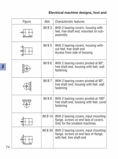
Electrical machine designs, foot and
Figure Abb. Characteristic features
IM B 3 With 2 bearing covers, housing withfeet, free shaft end, mounted on sub-assembly
IM B 5 With 2 bearing covers, housing with-out feet, free shaft end Access from side of housing
IM B 6 With 2 bearing covers pivoted at 90°,free shaft end, housing with feet, wallfastening
IM B 7 With 2 bearing covers pivoted at 90°,free shaft end, housing with feet, wallfastening
IM B 8 With 2 bearing covers pivoted at 180°,free shaft end, housing with feet, coverfastening
IM B 14 With 2 bearing covers, input mountingflange, screws on end face of covers.Only for the smallest machines.
IM B 34 With 2 bearing covers, input mountingflange, screws on end face of flange,with feet, free shaft end
75
5
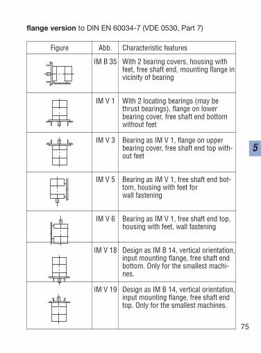
flange version to DIN EN 60034-7 (VDE 0530, Part 7)
Figure Abb. Characteristic features
IM B 35 With 2 bearing covers, housing withfeet, free shaft end, mounting flange invicinity of bearing
IM V 1 With 2 locating bearings (may be thrust bearings), flange on lower bearing cover, free shaft end bottomwithout feet
IM V 3 Bearing as IM V 1, flange on upperbearing cover, free shaft end top with-out feet
IM V 5 Bearing as IM V 1, free shaft end bot-tom, housing with feet for wall fastening
IM V 6 Bearing as IM V 1, free shaft end top,housing with feet, wall fastening
IM V 18 Design as IM B 14, vertical orientation,input mounting flange, free shaft endbottom. Only for the smallest machi-nes.
IM V 19 Design as IM B 14, vertical orientation,input mounting flange, free shaft endtop. Only for the smallest machines.
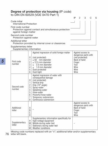
Against ingression of solid foreign matter Against access to dangerous parts with
0 (not protected) (not protected)
First code 1 ≥ 50 mm diameter Back of hand
number2 ≥ 12.5 mm diameter Finger3 ≥ 2.5 mm diameter Tool4 ≥ 1.0 mm diameter Wire5 Dust-protected Wire6 Dust-tight Wire
Against ingression of water with consequential damage
0 (not protected)1 Vertical drip
Second code2 Drip (15° angle)
number3 Spray-water4 Splashing water5 Hose-water6 Powerful hose-water7 Temporary submersion8 Continuous submersion
Against access to dangerous parts with
Additional A–
Back of handletter B Finger
C ToolD Wire
Supplementary information specifically for
SupplementaryH high-voltage equipment
letterM Mobile during water test –S Stationary during water testW Weather conditions
76
5
Degree of protection via housing (IP code) to DIN EN 60529 (VDE 0470 Part 1)
IP 2 3 C S
Code initialInternational Protection
First code numberProtection against contact and simultaneous protection against foreign matter
Second code numberProtection against water
Additional letterProtection provided by internal cover or clearances
Supplementary letterSupplementary information
Missing code numbers replaced with an “x”; additional letter and/or supplementaryletter left blank.
77
5
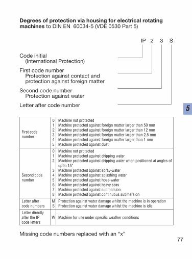
Degrees of protection via housing for electrical rotatingmachines to DIN EN 60034-5 (VDE 0530 Part 5)
IP 2 3 S
Code initial(International Protection)
First code numberProtection against contact and protection against foreign matter
Second code numberProtection against water
Letter after code number
Missing code numbers replaced with an “x”
0 Machine not protected1 Machine protected against foreign matter larger than 50 mm
First code 2 Machine protected against foreign matter larger than 12 mm
number 3 Machine protected against foreign matter larger than 2.5 mm4 Machine protected against foreign matter larger than 1 mm5 Machine protected against dust
0 Machine not protected1 Machine protected against dripping water2 Machine protected against dripping water when positioned at angles of
up to 15°3 Machine protected against spray-water
Second code 4 Machine protected against splashing waternumber 5 Machine protected against hose-water
6 Machine protected against heavy seas7 Machine protected against submersion8 Machine protected against continuous submersion
Letter after M Protection against water damage whilst the machine is in operationcode numbers S Protection against water damage whilst the machine is idle
Letter directlyafter the IP W Machine for use under specific weather conditionscode letters
78
5
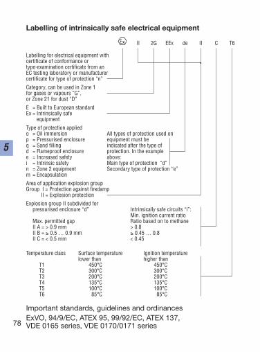
Labelling of intrinsically safe electrical equipment
Labelling for electrical equipment with certificate of conformance or type-examination certificate from anEC testing laboratory or manufacturer certificate for type of protection “n”Category, can be used in Zone 1 for gases or vapours “G”,or Zone 21 for dust “D”E = Built to European standardEx = Intrinsically safe
equipmentType of protection appliedo = Oil immersion All types of protection used onp = Pressurised enclosure equipment must beq = Sand filling indicated after the type ofd = Flameproof enclosure protection. In the examplee = Increased safety above:i = Intrinsic safety Main type of protection “d”n = Zone 2 equipment Secondary type of protection “e”m = EncapsulationArea of application explosion groupGroup I = Protection against firedamp
II = Explosion protectionExplosion group II subdivided for
pressurised enclosure “d” Intrinsically safe circuits “i”:Min. ignition current ratio
Max. permitted gap Ratio based on to methaneII A = > 0.9 mm > 0.8II B = ≥ 0.5 … 0.9 mm ≥ 0.45 … 0.8II C = < 0.5 mm < 0.45
Temperature class Surface temperature Ignition temperaturelower than higher than
T1 450°C 450°CT2 300°C 300°CT3 200°C 200°CT4 135°C 135°CT5 100°C 100°CT6 85°C 85°C
Important standards, guidelines and ordinancesExVO, 94/9/EC, ATEX 95, 99/92/EC, ATEX 137, VDE 0165 series, VDE 0170/0171 series
II 2G EEx de II C T6
79
5
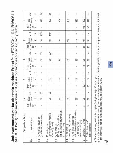
Tem
pera
ture
cla
ssA
EB
FH
Ther
-Re
sis-
Ther
-Re
sis-
Ther
-Re
sis-
Ther
-Re
sis-
Ther
-Re
sis-
No.
Meth
od o
f mea
s.m
ome-
tance
e.t.d
.m
ome-
tance
e.t.d
.m
ome-
tance
e.t.d
.m
ome-
tance
e.t.d
.m
ome-
tance
e.t.d
.ter
terter
terter
KK
KK
KK
KK
KK
KK
KK
K1
a)AC
wind
ings o
n 50
00 kW
(o
r kVA
) mac
hines
or m
ore
–60
651 )
––
––
8085
1 )–
100
1051
)–
125
1301
)
1 b)
AC w
inding
s on
< 50
00 kW
(or k
VA) m
achin
es–
6065
1 )–
75–
–80
901 )
–10
511
01)
–12
513
01)
> 20
0 kW
(or k
VA)
1 c)
AC w
inding
s on
200
kW (o
r kVA
) mac
hines
–60
––
75–
–80
––
105
––
125
–wi
th th
e exc
eptio
n of
wind
ings t
oNo
. 1 d
) or 1
e)2 )
1 d)
AC w
inding
s on
–65
––
75–
–85
––
110
––
130
–<
600
W (o
r VA)
mac
hines
2 )1
e)AC
wind
ings o
n m
achin
eswi
th se
lf-ve
ntila
tion,
with
out f
ans
–65
––
75–
–85
––
110
––
130
–(IC
40)
and/
or w
ithen
close
d wi
nding
s 2)
2Co
mm
utato
r wind
ings
5060
–65
75–
7080
–85
105
–10
512
5–
3Fie
ld wi
nding
s on
AC50
60–
6575
–70
80–
8510
5–
105
125
–an
d DC
mac
hines
1 )Th
ese
valu
es m
ay h
ave
to b
e ad
apte
d fo
r hig
h-vo
ltage
AC
win
ding
s.2 )
If th
e su
perp
ositi
on m
etho
d is
bei
ng u
sed
for w
indi
ngs
on m
achi
nes
< 20
0 kW
(or k
VA),
insu
late
d to
tem
pera
ture
cla
sses
A, E
, B a
nd F,
the
limit
valu
es s
et fo
r ove
rtem
pera
ture
s m
ay b
e ex
ceed
ed b
y 5
K.
Lim
it o
vert
emp
erat
ures
for
elec
tro
nic
mac
hine
s E
xtra
ct fr
om IE
C 6
0034
-1, D
IN E
N 6
0034
-1(V
DE
053
0 P
art 1
) Ove
rtem
pera
ture
lim
it va
lues
for
mac
hine
s co
oled
indi
rect
ly w
ith a
ir
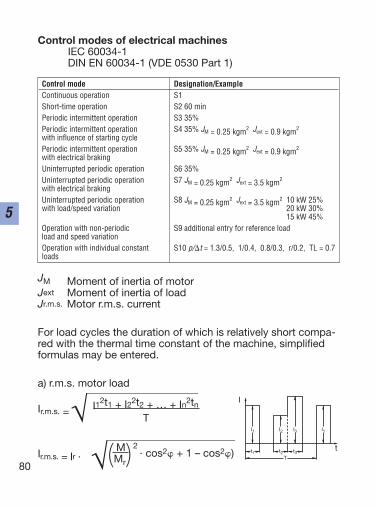
Control modes of electrical machinesIEC 60034-1DIN EN 60034-1 (VDE 0530 Part 1)
JM Moment of inertia of motorJext Moment of inertia of loadJr.m.s. Motor r.m.s. current
For load cycles the duration of which is relatively short compa-red with the thermal time constant of the machine, simplifiedformulas may be entered.
a) r.m.s. motor load
Ir.m.s. = I12t1 + I22t2 + … + In2tnT
Ir.m.s. = Ir ·M 2
· cos2 + 1 – cos2)(Mr)80
5
Control mode Designation/ExampleContinuous operation S1Short-time operation S2 60 minPeriodic intermittent operation S3 35%Periodic intermittent operation S4 35% JM = 0.25 kgm2 Jext = 0.9 kgm2
with influence of starting cyclePeriodic intermittent operation S5 35% JM = 0.25 kgm2 Jext = 0.9 kgm2
with electrical brakingUninterrupted periodic operation S6 35%Uninterrupted periodic operation S7 JM = 0.25 kgm2 Jext = 3.5 kgm2
with electrical brakingUninterrupted periodic operation S8 JM = 0.25 kgm2 Jext = 3.5 kgm2 10 kW 25%with load/speed variation 20 kW 30%
15 kW 45%Operation with non-periodic S9 additional entry for reference loadload and speed variationOperation with individual constant S10 p/t = 1.3/0.5, 1/0.4, 0.8/0.3, r/0.2, TL = 0.7loads
I
tT
I1 I2 I3
t1 t2 t3
I1
81
5
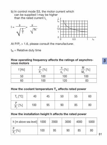
b) In control mode S3, the motor current which can be supplied I may be higher than the rated current Ir.
I = Ir = Irt tRT
At P/Pr > 1.6, please consult the manufacturer.
tR = Relative duty time
How operating frequency affects the ratings of asynchro-nous motors
How the coolant temperature Tc affects rated power
How the installation height h affects the rated power
0 0,5 1 tR
0
1
2
IIN
1,6
f [Hz]P
[%]n
[%]M
[%]Pr . nr . Mr .
50 100 100 10060 100 120 83
Tc [°C] 40 45 50 55 60
P[%] 100 95 90 85 80
Pr .
h [m above sea level] 1000 2000 3000 4000 5000
P[%] 100 95 90 85 80
Pr .
82
5
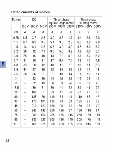
Rated currents of motors
Power DC Three-phase Three-phasesquirrel-cage motor slipring motor
150 V 260 V 440 V 230 V 400 V 500 V 230 V 400 V 500 V
kW A A A A A A A A A
0.75 6.5 3.7 2.3 3.9 2.3 1.7 4.4 2.6 2.01.1 9.7 6.0 3.6 5.1 3.0 2.3 6.5 3.8 2.91.5 13 8.1 4.8 6.8 3.9 3.0 8.5 5.0 3.72.2 20 12 7.1 9.6 5.5 4.2 12 6.6 5.13.0 25 15 10 14 7.9 6.0 15 8.2 6.23.7 31 19 11 17 9.7 7.4 18 10 7.64.0 33 20 12 18 11 7.6 19 11 8.35.5 44 27 16 23 14 10 24 14 117.5 58 36 21 31 18 14 31 18 1411 – 52 30 44 25 19 44 25 1915 – 72 43 56 33 26 56 33 26
18.5 – 89 51 69 41 32 69 41 3222 – 100 61 83 47 36 82 47 3630 – 135 80 110 64 48 110 66 4737 – 170 101 135 79 59 135 80 5845 – 210 123 160 95 72 160 93 7055 – 240 143 200 120 87 190 110 8475 – 330 192 265 155 115 250 150 11090 – 380 225 305 180 140 305 175 140110 – 465 275 380 220 165 365 215 150
83
5
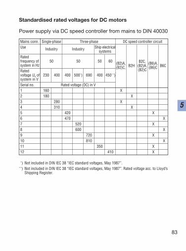
Standardised rated voltages for DC motors
Power supply via DC speed controller from mains to DIN 40030
Mains conn. Single-phase Three-phase DC speed controller circuitUse Industry Industry Ship electrical
systemsRated frequency of 50 50 50 60system in HzRatedvoltage Un of 230 400 400 500*) 690 400 450**)system in VSerial no. Rated voltage (DC) in V1 160 X2 180 X3 280 X4 310 X5 420 X6 470 X7 520 X8 600 X9 720 X10 810 X11 350 X12 410 X
(B2)A, B2C, (B6)A,(B2)C, B2H (B2)A, (B6)C B6C
(B2)C
*) Not included in DIN IEC 38 “IEC standard voltages, May 1987”.**) Not included in DIN IEC 38 “IEC standard voltages, May 1987”. Rated voltage acc. to Lloyd’s
Shipping Register.
no = 60 f = 120 fp 2p
n = no (1 – s) = 60 f (1 – s)p
s = no – nno
s = 0 Synchronism
s = 1 Rotor speed n = 0
84
5
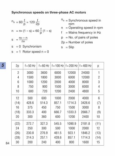
Synchronous speeds on three-phase AC motors
no = Synchronous speed inrpm
n = Operating speed in rpm
f = Mains frequency in Hz
p = No. of pairs of poles
2p = Number of poles
s = Slip
2p f = 50 Hz f = 60 Hz f = 100 Hz f = 200 Hz f = 400 Hz p
2 3000 3600 6000 12000 24000 14 1500 1800 3000 6000 12000 26 1000 1200 2000 4000 8000 38 750 900 1500 3000 6000 4
10 600 720 1200 2400 4800 5
12 500 600 1000 2000 4000 6(14) 428.6 514.3 857.1 1714.3 3428.6 (7)16 375 450 750 1500 3000 8
(18) 333.3 400 666.7 1333.3 2666.7 (9)20 300 360 600 1200 2400 10
(22) 272.7 327.3 545.5 1090.9 2181.8 (11)24 250 300 500 1000 2000 12
(26) 230.8 276.9 461.5 923.1 1846.2 (13)(28) 214.3 257.1 428.6 857.1 1714.3 (14)30 200 240 400 800 1600 15
Installation of equipment
85
6
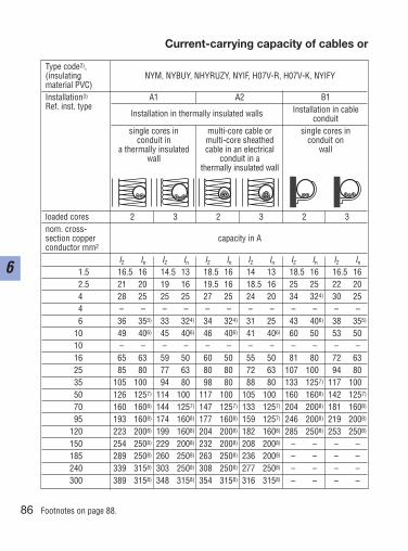
Current-carrying capacity of cables or
86
6
Type code2),(insulating NYM, NYBUY, NHYRUZY, NYIF, H07V-R, H07V-K, NYIFYmaterial PVC)Installation3) A1 A2 B1Ref. inst. type
Installation in thermally insulated walls Installation in cable conduit
single cores in multi-core cable or single cores inconduit in multi-core sheathed conduit on
a thermally insulated cable in an electrical wallwall conduit in a
thermally insulated wall
loaded cores 2 3 2 3 2 3nom. cross-section copper capacity in Aconductor mm2
IZ In IZ In IZ In IZ In IZ In IZ In
1.5 16.5 167) 14.5 137) 18.5 167) 14 137) 18.5 167) 16.5 167)
2.5 21 207) 19 167) 19.5 167) 18.5 167) 25 257) 22 207)
4 28 257) 25 257) 27 257) 24 207) 34 324) 30 257)
4 – – – – – – – – – – – –6 36 355) 33 324) 34 324) 31 257) 43 406) 38 355)
10 49 406) 45 406) 46 406) 41 406) 60 507) 53 507)
10 – – – – – – – – – – – –16 65 637) 59 507) 60 507) 55 507) 81 807) 72 637)
25 85 807) 77 637) 80 807) 72 637) 107 1007) 94 807)
35 105 1007) 94 807) 98 807) 88 807) 133 1257) 117 1007)
50 126 1257) 114 1007) 117 1007) 105 1007) 160 1608) 142 1257)
70 160 1608) 144 1257) 147 1257) 133 1257) 204 2008) 181 1608)
95 193 1608) 174 1608) 177 1608) 159 1257) 246 2008) 219 2008)
120 223 2008) 199 1608) 204 2008) 182 1608) 285 2508) 253 2508)
150 254 2508) 229 2008) 232 2008) 208 2008) –. – . –. – .185 289 2508) 260 2508) 263 2508) 236 2008) –. – . –. – .240 339 3158) 303 2508) 308 2508) 277 2508) –. – . –. – .300 389 3158) 348 3158) 354 3158) 316 3158) –. – . –. – .
Footnotes on page 88.
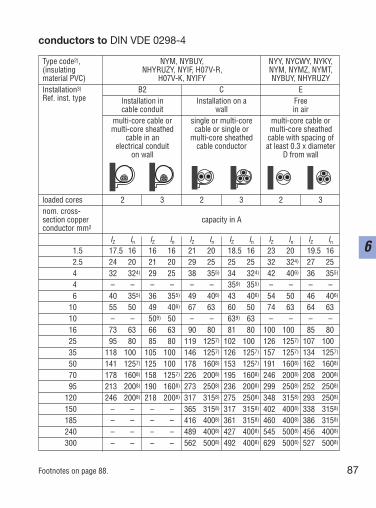
Type code2), NYM, NYBUY, NYY, NYCWY, NYKY,(insulating NHYRUZY, NYIF, H07V-R, NYM, NYMZ, NYMT,material PVC) H07V-K, NYIFY NYBUY, NHYRUZYInstallation3) B2 C ERef. inst. type Installation in Installation on a Free
cable conduit wall in airmulti-core cable or single or multi-core multi-core cable ormulti-core sheathed cable or single or multi-core sheathed
cable in an multi-core sheathed cable with spacing ofelectrical conduit cable conductor at least 0.3 x diameter
on wall D from wall
loaded cores 2 3 2 3 2 3nom. cross-section copper capacity in Aconductor mm2
IZ In IZ In IZ In IZ In IZ In IZ In
1.5 17.5 167) 16 167) 21 207) 18.5 167) 23 207) 19.5 167)
2.5 24 207) 21 207)) 29 257)) 25 257) 32 324) 27 257)
4 32 324)) 29 257) 38 355)) 34 324)) 42 406) 36 355)
4 – – – – – – 359) 355) – – – –6 40 355) 36 355) 49 406) 43 406) 54 506) 46 406)
10 55 506) 49 406) 67 636) 60 506) 74 637) 64 637)
10 – – 509) 50 – – 639) 63 – – – –16 73 637) 66 637) 90 807) 81 807) 100 1007) 85 807)
25 95 807) 85 807) 119 1257)) 102 1007) 126 1257)) 107 1007)
35 118 1007) 105 1007) 146 1257) 126 1257) 157 1257) 134 1257)
50 141 1257) 125 1007) 178 1608) 153 1257) 191 1608) 162 1608)
70 178 1608) 158 1257) 226 2008) 195 1608) 246 2008) 208 2008)
95 213 2008) 190 1608) 273 2508) 236 2008) 299 2508) 252 2508)
120 246 2008) 218 2008) 317 3158) 275 2508) 348 3158) 293 2508)
150 –. – . –. – . 365 3158) 317 3158) 402 4008) 338 3158)
185 –. – . –. – . 416 4008) 361 3158) 460 4008). 386 3158)
240 –. – . –. – . 489 4008) 427 4008) 545 5008) 456 4008)
300 –. – . –. – . 562 5008) 492 4008) 629 5008) 527 5008)
87
6
conductors to DIN VDE 0298-4
Footnotes on page 88.
88
6
Current-carrying capacities Iz1) of cables or conductors for fixed installation (installation type
A1, A2, B1, B2, C and E) with a permissible conductor temperature of 70 °C and an ambienttemperature of 25 °C (Tables A.1 and A.2 from DIN VDE 0298-4 (VDE 0298 Part 4): 1998-11,collated and modified), as well as the selection of overcurrent protection devices for protectionagainst overload.
1) The current-capacity for cables with concentric cores applies only to multi-core versions.Other current-capacity values for cables are to be found in DIN VDE 0276-603 (VDE 0276Part 603), Section 3G, Table 15
2) A list of type codes and details on the standards met by the cables and conductors is to befound in DIN VDE 0298-1 (VDE 0298 Part 1) and DIN VDE 0298-3 (VDE 0298 Part 3)
3) Further installation types; see tables 2 and 7 of DIN VDE 0298-4 (VDE 0298 Part 4)4) In = 25 A with D- and D0-fuses, which are (at present) not available in Germany for the
current rating In = 32 A5) In = 32 A with curcuit-breakers, which are (at present) not available in Germany for the
current rating In = 35 A6) In = 35 A with D- and D0-fuses, which are (at present) not available in Germany for the
current rating In = 40 A7) At present, D- and D0-fuses are available up to a maximum rating In = 100 A8) At present, curcuit-breakers are available up to a maximum rating In = 125 A, see also
footnote 79) Not valid for installation on a wooden wall
Ib = operating current of the circuitIn = rated or set current of the protective deviceIZ = permissible current loading of the conductor or cableIz = tripping currentConditions:Ib In IZ
Iz 1,45 IZ
Footnotes to table:Current-carrying capacity of cables orconductors to DIN VDE 0298-4
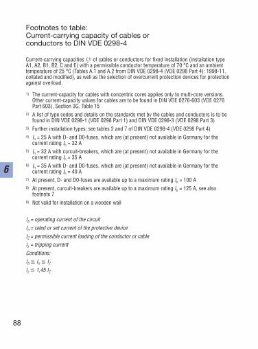
External diameters of conductors and cablesThe external diameters are average values from different manufacturersNYM sheathed cableNYY cable with plastic sheathingH 05 RR-F light rubber-sheathed cable
(NMH + NMH) DIN 57282H 05 RN-F heavy rubber-sheathed cable
(NMH + NSH) DIN 57282NYCY cable with concentric conductors and
plastic sheathingNYCWY cable with concentric undulating
conductors and plastic sheathing
No. approx. external diameterof conductors NYM NYY H 05 H 07 NYCY
RR-F RN-F
Cross-sectionmm2 mm mm mm mm mm2 x 1.5 10 11 9 10 122 x 2.5 11 13 13 11 143 x 1.5 10 12 9 10 133 x 2.5 11 13 10 12 143 x 4 13 17 – 14 153 x 6 15 18 – 16 163 x 10 18 20 – 23 183 x 16 20 22 – 25 224 x 1.5 11 13 9 11 134 x 2.5 12 14 11 13 154 x 4 14 16 – 15 164 x 6 16 19 – 17 184 x 10 18 23 – 23 214 x 16 22 27 – 27 244 x 25 27 28 – 32 304 x 35 30 28 – 36 314 x 50 – 30 – 42 344 x 70 – 34 – 47 384 x 95 – 39 – 53 434 x 120 – 42 – – 464 x 150 – 47 – – 524 x 185 – 55 – – 604 x 240 – 62 – – 705 x 1.5 11 14 11 14 155 x 2.5 13 15 13 17 175 x 4 15 17 – 19 185 x 6 17 19 – 21 205 x 10 20 21 – 26 –5 x 16 25 23 – 30 –8 x 1.5 – 15 – – –10 x 1.5 – 18 – – –16 x 1.5 – 20 – – –24 x 1.5 – 25 – – –
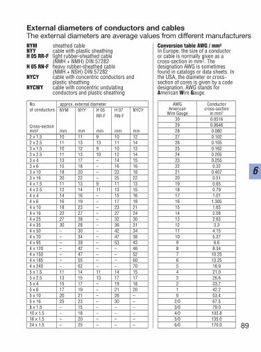
Conversion table AWG / mm2
In Europe, the size of a conductoror cable is normally given as across-section in mm2. Thedesignation AWG is sometimesfound in catalogs or data sheets. Inthe USA, the diameter or cross-section of cores is given by a codedesignation. AWG stands forAmerican Wire Gauge.
89
6
AWG ConductorAmerican cross-section
Wire Gauge in mm2
30 0.051629 0.064628 0.08027 0.10226 0.10525 0.16224 0.20523 0.25522 0.3221 0.40720 0.5119 0.6518 0.7917 1.0116 1.30515 1.6514 2.0813 2.6312 3.311 4.1510 5.279 6.68 8.347 10.256 13.255 16.94 21.03 26.62 33.71 42.20 53.4
2/0 67.53/0 79.04/0 103.85/0 135.06/0 170.0
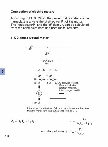
Connection of electric motors
According to EN 60034-5, the power that is stated on the nameplate is always the shaft power P2 of the motor. The input powerP1 and the efficiency can be calculated from the nameplate data and from measurements.
1. DC shunt-wound motor
P1 = UA IA + UF IF =P2
UA IA + UF IF
armature efficiency A =P2
UA IA90
6
Clockwise rotationIf anti-clockwiserotation required,interchange J and K
If the armature (rotor) and field (stator) voltages are the same,then the motor terminals J, K are labelled as C, D
Simplatronunit
A B J K
A A
V
JA
UA
1B1
2B2
V
JF
UF
F1 F2
M––
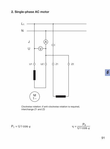
2. Single-phase AC motor
P1 = U I cos =P2
U I cos
91
6
M1~
AJ
U
L1
N
V
Clockwise rotation: if anti-clockwise rotation is required,interchange Z1 and Z2
U1 U2 Z1 Z2
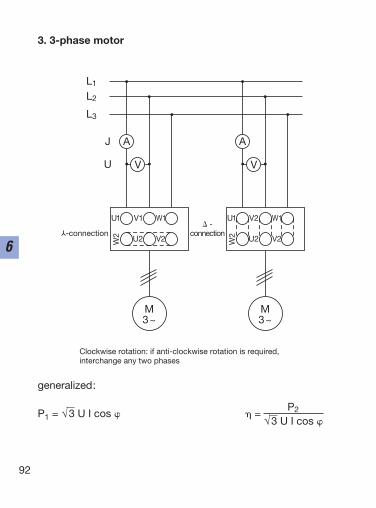
3. 3-phase motor
generalized:
P1 = √3 U I cos =P2
√3 U I cos
92
6
U1 V1 W1
U2 V2W2
M3~
AJ
U
L1
L2
L3
V
U1 V2 W1
U2 V2W2
M3~
A
V
Clockwise rotation: if anti-clockwise rotation is required,interchange any two phases
-connection -
connection
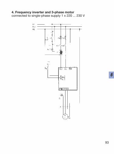
4. Frequency inverter and 3-phase motorconnected to single-phase supply 1 x 220 ... 230 V
93
6
94
6
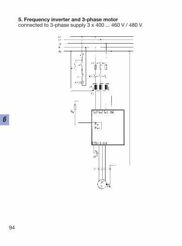
5. Frequency inverter and 3-phase motorconnected to 3-phase supply 3 x 400 ... 460 V / 480 V
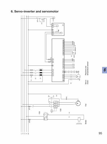
6. Servo-inverter and servomotor
95
6
K1
K1
L3 N PEL1 L2
UV
W
M 3˜P
E
L1
L2
L3
K1
F1
... F
3
PE
+UG
-UG
PE
+UG
-UG
PE
A3
28E
1E
2E
3E
4E
5A
1A
259
39A
4
+
12
34
763
-
762
Z1
X1
Z2
K1
OF
F ON
RF
R
RB
T1
T2
RX6
F4
F5
-
+
1F6
1F7
1G6
230V
˜
VD
C
13 14 2.8
I>>
I>>
I>>
13
5
24
6
1Q6
Y2
PE
M ˜
-+
Bra
ke
F
an
S
ervo
-
Res
olve
r an
d
mot
or
tem
per
atur
e se
nsor
Y1

96
6

Approvals and standards
97
7
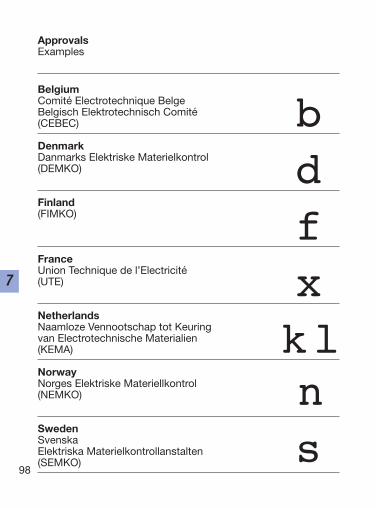
BelgiumComité Electrotechnique Belge Belgisch Elektrotechnisch Comité (CEBEC)
DenmarkDanmarks Elektriske Materielkontrol(DEMKO)
Finland(FIMKO)
FranceUnion Technique de l’Electricité (UTE)
NetherlandsNaamloze Vennootschap tot Keuringvan Electrotechnische Materialien(KEMA)
NorwayNorges Elektriske Materiellkontrol (NEMKO)
SwedenSvenskaElektriska Materielkontrollanstalten (SEMKO)
98
7
s
ApprovalsExamples
bdfxkln

99
7
SwitzerlandSchweizerischer Elektrotechnischer Verein (SEV)
GermanyVerband Deutscher Elektrotechniker(VDE)
AustriaÖsterreichischer Verband für Elektrotechnik(ÖVE)
USAUnderwriters Laboratories Listing(UL)
Recognition
CanadaCanadian Standards Association(CSA)
RussiaGosstandart(GOST Re)
There are new approval requirements in the following countries:Slovakia, Poland, South Africa, China and Russia
tvj
ura

100
7
Approval establishments
USAUSAUL
CanadaCDNCSA
CroatiaCROZIK
RomaniaROICECON
RussiaRUSGOST-R
Czech RepublicCREZU
HungaryHMEEI
South AfricaSASABS
SlovakiaSKSKTC
ua

101
7
Shipping registration
GermanyGermanischer LloydGL
Great BritainLloyd’s Register of ShippingLR
FranceBureau VeritasBV
RussiaRussian Maritime Register of ShippingRS
ItalyRegistro Italiano NavaleRINA
NorwayDet Norske VeritasDNV
PolandPolski Rejestr StatkowPRS
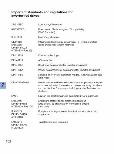
102
7
Important standards and regulations for inverter-fed drives
73/23/EEC Low voltage Directive
89/336/EEC Directive on Electromagnetic Compatibility (EMC Directive)
98/37/EC Machinery directive
CISPR 22 Information technology equipment: RFI-characteristicsEN 55022 limits and measurement methodsDIN EN 55022(VDE 0878 Part 22)
DIN 19226 Control technology
DIN 40110 AC-variables
DIN 41751 Cooling of semiconductor inverter equipment
DIN 41752 Power designations of semiconductor inverter equipment
DIN 41756 Loading of inverters, operating modes, loading classes andload types
DIN VDE 0298-4 Use of cables and isolated conductors for power plants; re-commended value for maximum current capacity of cablesand conductors for laying in buildings and of flexible con-ductors
EMVG Law on the electromagnetic compatibility of equipment
EN 50102 Enclosure protection for electrical apparatusDIN EN 50102 (equipment) against exterior mechanical effects(VDE 0470 Part 100) (IK-Code)
EN 50178 Equipment for high-current installations with electronicDIN EN 50178 apparatus(VDE 0160)
EN 50216 Transformers and inductorsDIN EN 50216(VDE 0532)
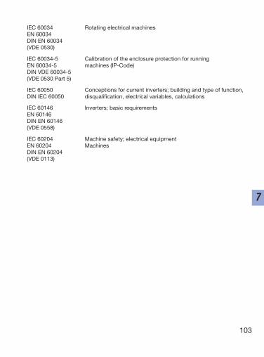
103
7
IEC 60034 Rotating electrical machinesEN 60034DIN EN 60034(VDE 0530)
IEC 60034-5 Calibration of the enclosure protection for running EN 60034-5 machines (IP-Code)DIN VDE 60034-5(VDE 0530 Part 5)
IEC 60050 Conceptions for current inverters; building and type of function, DIN IEC 60050 disqualification, electrical variables, calculations
IEC 60146 Inverters; basic requirementsEN 60146DIN EN 60146(VDE 0558)
IEC 60204 Machine safety; electrical equipmentEN 60204 MachinesDIN EN 60204(VDE 0113)
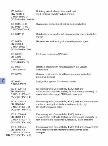
104
7
IEC 60349-2 Rotating electrical machines in rail and ENV 60349-2 road vehicles; inverter-fed AC motorsDIN EN 60349-2(VDE 0115 Part 400-2)
IEC 60364-4-43 Overcurrent protection of cables and conductorsIEC 60364-4-473DIN VDE 0100-430
IEC 60411-2 Conductor inverters for rail; complementary technical infor-mation
IEC 60439-1 Requirement and testing of low-voltage switchgearEN 60439-1DIN EN 60439-1(VDE 0660 Part 500)
IEC 60529 Enclosure protection (IP Code)EN 60529DIN EN 60529(VDE 0470 Part 1)
IEC 60664 Isolation coordination for apparatus in low voltage DIN VDE 0110 installations
IEC 60755 General requirements for difference-current activatedprotective devices
IEC 60971 Designation system for inverter circuitsDIN IEC 60971
IEC 61000-4-2 Electromagnetic Compatibility (EMC); test and EN 61000-4-2 measurement methods; testing for interference immunity toDIN EN 61000-4-2 electrostatic discharge; EMC basic standard(VDE 0847 Part 4-2)
IEC 61000-4-3 Electromagnetic Compatibility (EMC); test and measurementEN 61000-4-3 methods; testing for interference immunity to highDIN EN 61000-4-3 HF electromagnetic fields(VDE 0847 Part 4-3)
IEC 61000-4-4 Electromagnetic Compatibility (EMC); test and EN 61000-4-4 measurement methods; testing for interference immunity to DIN EN 61000-4-4 fast electrostatic transients/bursts; EMC basic standard(VDE 0847 Part 4-4)
IEC 61000-4-5 Electromagnetic Compatibility (EMC); test and measurementEN 61000-4-5 methods; testing for interference immunity to pulseDIN EN 61000-4-5 voltages(VDE 0847 Part 4-5)
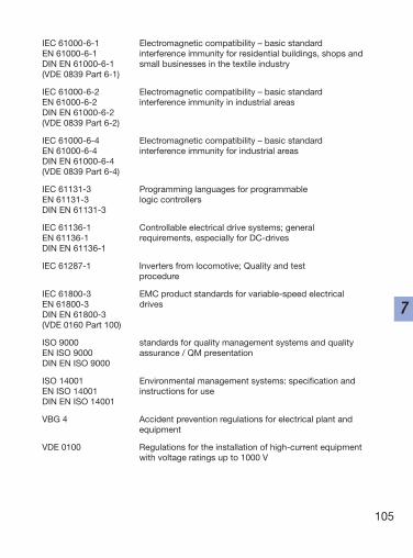
IEC 61000-6-1 Electromagnetic compatibility – basic standard EN 61000-6-1 interference immunity for residential buildings, shops and DIN EN 61000-6-1 small businesses in the textile industry(VDE 0839 Part 6-1)
IEC 61000-6-2 Electromagnetic compatibility – basic standard EN 61000-6-2 interference immunity in industrial areasDIN EN 61000-6-2(VDE 0839 Part 6-2)
IEC 61000-6-4 Electromagnetic compatibility – basic standard EN 61000-6-4 interference immunity for industrial areasDIN EN 61000-6-4(VDE 0839 Part 6-4)
IEC 61131-3 Programming languages for programmable EN 61131-3 logic controllersDIN EN 61131-3
IEC 61136-1 Controllable electrical drive systems; generalEN 61136-1 requirements, especially for DC-drivesDIN EN 61136-1
IEC 61287-1 Inverters from locomotive; Quality and test procedure
IEC 61800-3 EMC product standards for variable-speed electricalEN 61800-3 drivesDIN EN 61800-3(VDE 0160 Part 100)
ISO 9000 standards for quality management systems and qualityEN ISO 9000 assurance / QM presentationDIN EN ISO 9000
ISO 14001 Environmental management systems: specification andEN ISO 14001 instructions for useDIN EN ISO 14001
VBG 4 Accident prevention regulations for electrical plant and equipment
VDE 0100 Regulations for the installation of high-current equipmentwith voltage ratings up to 1000 V
105
7
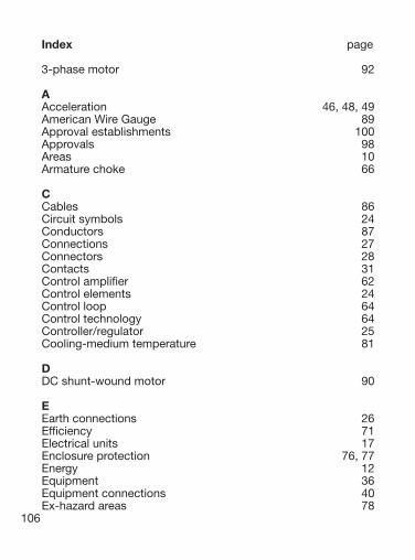
Index page
3-phase motor 92
AAcceleration 46, 48, 49American Wire Gauge 89Approval establishments 100Approvals 98Areas 10Armature choke 66
CCables 86Circuit symbols 24Conductors 87Connections 27Connectors 28Contacts 31Control amplifier 62Control elements 24Control loop 64Control technology 64Controller/regulator 25Cooling-medium temperature 81
DDC shunt-wound motor 90
EEarth connections 26Efficiency 71Electrical units 17Enclosure protection 76, 77Energy 12Equipment 36Equipment connections 40Ex-hazard areas 78
106
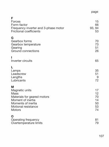
page
FForces 15Form-factor 66Frequency inverter and 3-phase motor 93, 94Frictional coefficients 53
GGearbox forms 70Gearbox temperature 73Gearing 51Ground connections 26
IInverter circuits 65
LLamps 35Leadscrew 51Lengths 9Lubricants 72
MMagnetic units 17Mass 12Materials for geared motors 70Moment of inertia 14Moments of inertia 50Motional resistance 53Motors 74
OOperating frequency 81Overtemperature limits 79
107
page
PPassive components 29Positioning drive 54Power 15, 45Pressure 15Protective device 35
RRegulations 102Relays 34Resistors 41Rotation 44
SSemiconductors 30Shipping registration 101Signal devices 35Single-phase AC motor 91Site altitude 81Speed (velocity) 45Standards 102Switches 33
TTemperature 16Temperature measurement 16Torque 13Torsional angle 52Translation 44Transport roller 51
VVoltage ratings for DC motors 83Volume 11
108

page
WWinder dimensioning 58Winding 57
109