the company jakob - easyfairs company jakob jakob ... length dimensions according to din iso 2768 mh...
TRANSCRIPT

The company JAKOB
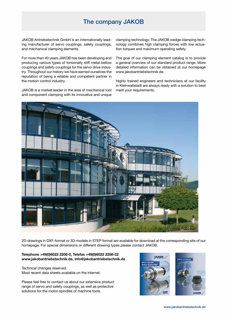
JAKOB Antriebstechnik GmbH is an internationally lead-ing manufacturer of servo couplings, safety couplings, and mechanical clamping elements.
For more than 40 years JAKOB has been developing and producing various types of torsionally stiff metal bellow couplings and safety couplings for the servo drive indus-try. Throughout our history we have earned ourselves the reputation of being a reliable and competent partner in the motion control industry.
JAKOB is a market leader in the area of mechanical tool and component clamping with its innovative and unique
clamping technology. The JAKOB wedge clamping tech-nology combines high clamping forces with low actua-tion torques and maximum operating safety.
The goal of our clamping element catalog is to provide a general overview of our standard product range. More detailed information can be obtained at our homepage www.jakobantriebstechnik.de.
Highly trained engineers and technicians at our facility in Kleinwallstadt are always ready with a solution to best meet your requirements.
2D-drawings in DXF-format or 3D-models in STEP format are available for download at the corresponding site of our homepage. For special dimensions or different drawing types please contact JAKOB.
Telephone +49(0)6022 2208-0, Telefax +49(0)6022 2208-22www.jakobantriebstechnik.de, [email protected]
Technical changes reserved.Most recent data sheets available on the internet.
Please feel free to contact us about our extensive product range of servo and safety couplings, as well as protective solutions for the motor-spindles of machine tools.
www.jakobantriebstechnik.de

Directory Clamping Elements I Overview
Mechanical Power Clamping Nut MCA with blind hole thread thread protected MDA centered operation compact design MCG optional with Star- or T-bolt with through hole thread unlimited clamping stroke for variable clamping edges
Hydromechanical Clamping Nut HMG maximum clamping forces over 4000 kN HMP multi-piston system with spring and oil return HMP-HD operating pressure 700 bar up to 1200 bar HVV custom thread available
Mechanical Power Clamping Screws SC wedge mechanism as force booster high clamping force at low actuation torque maximum operating safety – self-locking mechanism simple, manual operation
Mechanical and Hydromechanical Power Clamping Screws MSP for face plates and jaw boxes MSPD mechanical force amplifier for external clamping direction HSP double acting version for internal and external clamping directions hydromechanical force amplifying for external clamping direction nominal clamping forces up to 750 kN low actuation torques high operating travel maximum reliability simple handling and mounting
Force Monitoring FMS increase in operational safety HMD confirmation of proper clamping state
Hydromechanical Spring Clamping Systems ZSF spring clamping cylinder (pull) ZDF spring clamping cylinder (push) mechanical clamping hydraulically released maximum operating safety leak-proof and robust nominal clamping forces up to 350 kN
Sectional Rail Couplings PKV coupling/decoupling of sectional rails PKH vertical/horizontal versions manual or pneumatic operation available for all common rail dimensions
page
www.jakobantriebstechnik.de
1-6
7-12
13-15
16-20
21-24
25-30
31-35
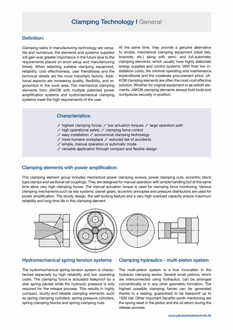
Hydromechanical spring tension systems
The hydromechanical spring tension system is charac-terized especially by high reliability and low operating costs. The clamping force is actuaded leakproof by a disk spring packet while the hydraulic pressure is only required for the release process. This results in highly compact, sturdy and reliable clamping elements, such as spring clamping cylinders, spring pressure cylinders, spring clamping blocks and spring clamping nuts.
Clamping hydraulics - multi-piston system
The multi-piston system is a true innovation in the hydraulic clamping sector. Several small pistons, which are interconnected using hydraulics, can be arranged concentrically or in any other geometric formation. The highest possible clamping forces can be generated thanks to a sealing, guaranteed to be leakproof up to 1500 bar. Other important benefits worth mentioning are the spring reset in the piston and the oil return during the release process.
Clamping Technology I General
Definition:
Clamping tasks in manufacturing technology are versa-tile and numerous; the elements and systems supplied will gain ever greater importance in the future (due to the requirements placed on short setup and manufacturing times). When selecting suitable clamping equipment, reliability, cost effectiveness, user friendliness and the technical details are the most important factors. Addi-tional aspects are increasing quality, flexibility, and er-gonomics in the work area. The mechanical clamping elements from JAKOB with multiple patented power amplification systems and hydromechanical clamping systems meet the high requirements of the user.
At the same time, they provide a genuine alternative to simple, mechanical clamping equipment (steel ties, brackets, etc.) along with semi- and full-automatic clamping elements, which usually have highly elaborate energy supplies and control systems. With their low in-stallation costs, the minimal operating and maintenance expenditures and the moderate procurement price, JA-KOB clamping elements are often the most cost effective solution. Whether for original equipment or as retrofit ele-ments, JAKOB clamping elements always hold tools and workpieces securely in position.
Characteristics:
highest clamping forces low actuation torques large operation path high operational safety clamping force control easy installation economical clamping technology more humane workplace reduced risk of accidents simple, manual operation or automatic mode versatile application through compact and flexible design
Clamping elements with power amplification:
This clamping element group includes mechanical power clamping screws, power clamping nuts, eccentric block type clamps and sectional rail couplings. They are designed for manual operation with simple handling but at the same time allow very high clamping forces. The manual actuation torque is used for clamping force monitoring. Various clamping mechanisms such as key systems, planet gears, eccentric principles and pressure distributors are used for power amplification. The sturdy design, the self-locking feature and a very high overload capacity ensure maximum reliability and long time life in this clamping element.
www.jakobantriebstechnik.de


Mechanical Power Clamping Nut I Series MCA-S/MCA-T
maximum clamping forces through force amplification simple, manual operation – low actuation torques high operational safety through self-locking mechanism corrosion - resistant, robust, up to 400°C
Mechanical Power Clamping Nut I Series MCA/MDA
2 clamping elements
The salient design feature of the MCA and MDA series is an integral transmission gear for the amplification of the manual actuation torque. With this, the user has a sturdyand flexible clamping element, which allows high clamp-ing forces with simple manual operation and maximum operational safety. The MCA Series is designed with bottomed thread and centered hexagon, the MDA Series with a through hole thread and sidewise arranged hexagon design. The pow-er clamping nut can be used for various clamping tasks throughout the machine tool industry, particularly for clamping in presses and punches.
Available options:
high temperature version up to T = 400°C (e.g. forging presses)
corrosion-resistant version for demanding ambient conditions
with additional latch mechanism for automatic switch over to power clamping mode for fast feeding or in a lowered layout (standard in types MCA 60, MCA-T, MCA-S)
lubrication with food grease for the food industry, laboratory area, etc.
with additional nipple for re-lubrication torque wrench or operation tools upon request
Application example:
MCA-power clamping nut for clamping of upper andlower die in a hydraulic press.
Function and handling:
After manually tightening the clamping nut up to the sur-face, the drive pinion is activated through a right-hand turn of the actuation hexagon SW 1 or SW 2. The gearbox ratio tightens the torque with a high multiplier and the ro-tation of the threaded nut produces the clamping stroke of the threaded tension bolt. The clamping force is built up depending on the actuation torque. Self-locking is guaranteed in every clamping position. To reliably ensure the necessary clamping force on one hand and to protect the clamping mechanism from damage caused by excessive actuation torques on the other, the use of a torque wrench is recommended. In certain circumstances, clamping with the help of normal box spanners, angle wrenches and ratchet spanners may be acceptable while the use of impact wrenches is not. Make sure that the threaded-down stud bolts are fixed; i.e., that they cannot be turned. The power clamping nuts are maintenance-free under normal operating conditions. The tempered steel housing and threaded nut are corro-sion-resistant through surface-nitriding.
www.jakobantriebstechnik.de

Mechanical Power Clamping Nut I Series MCA-S/MCA-T
simple, manual operation with handle fast infeed motion due to automatic change over
Ordering example: MCA-S - M 16 / MCA-T - M 20
nominal max static screw in depth weight Series clamping force thread load tmin tmax approx. [kN] [kN] [mm] [kg] M 10 50 MCA-S M 12 70 MCA-T
40 M 16 120
16 24 1,0
M 20 120
Technical data and dimensions [mm]: length dimensions according to DIN ISO 2768 mH
clamping nut MCA-S with star grip
clamping nut MCA-T with T-grip
ratchet ratchet
Notice:Property class of threaded bolt should be at least Q10.9. Sizes of thread larger than M 16, should use a property class of Q 12.9, or the max. stat-ic load must be reduced. For optical control of actual screw-in depth of the T-bolt, two grooves are cut into the housing circumference matching tmin and tmax. When laying out the actual screw-in depth of the threaded bolt, the necessary stroke must be considered i. e. the max. specified screw-in depth must be reduced by at least the amount of the stroke.
Application example:MCA-T-clamping nut for adjustment of test bench sliding table
Material:heat treated steel - nitro carburizedcover plate: high tensile aluminum
www.jakobantriebstechnik.de clamping elements 3
Mechanical Power Clamping Nut I Series MCA/MDA

Mechanical Power Clamping Nut I Series MDAMechanical Power Clamping Nut I Series MCA
with bottomed thread thread protected centered operation compact design
www.jakobantriebstechnik.de
nominal nominal max. MCA clamping thread actuation static T-bolt DIN 650 weight screw-in depth
force D* torque load m H approx. Øa Ød1 Ød2 L t SW 1 w
Size [kN] [Nm] [kN] min/max [kg] min max
M 12 20 70 14 14 / 19 60 60 M 16 25 120 18 18 / 24 0,9 62 32 60 50 16 24 13 10 M 20 30 120 22 22 / 29 M 16 35 130 18 18 / 24 M 20 40 200 22 22 / 29
100 100 M 24 45 200 28 28 / 36
1,8 73 42 71 70 25 35 15 10
M 30 50 200 36 36 / 46 M 24 60 300 28 28 / 36 2,5 M 30 70 300 36 36 / 46 2,4 150 150
M 36 75 300 42 42 / 53 2,3 83 52 81 75 30 40 17 12
M 42 80 300 48 48 / 59 2,2 M 36 90 400 42 42 / 53 4,9 M 42 95 450 48 48 / 59 4,8 200 200 M 48 100 450 54 54 / 66 4,7 120 82 118 80 35 45 19 12 M 56 105 500 - - 4,5 M 64 115 500 - - 4,3
Technical data and dimensions [mm]: length dimensions according to DIN ISO 2768 mH
* Property class of threaded bolt up to M 24 minimum Q 10.9; from M 30 Q 8.8 (further thread sizes i. e. inches on request) - max. allowed temperature range: -30°C up to +200°C (optional up to 400°C)
Ordering example: clamping nut MCA 100 - M 24 incl. T-bolt MCA 150 - M 30 - 60 - 40
series and sizethread size (T-bolt screw thread according to DIN 787)clamping height (h = 60 mm)size of T-bolt (H = 40 mm)
table surface
T-boltDIN 787to M24: 10.9/12.9from M30: 8.8
Note:For optical control of actual screw-in depth of the T-bolt, two grooves have been provided on the housing circumfer-ence matching tmin and tmax. When laying out the actual screw-in depth of the threaded bolt, the necessary stroke must be considered, i. e. the max. specified screw-in depth must be reduced at least by the amount of the stroke.
Material:heat treated steel - nitro carburizedcover plate: high tensile aluminum
4 clamping elements

clamping elements 5
Mechanical Power Clamping Nut I Series MDA
with through hole thread for variable clamping edges unlimited clamping stroke
Technical data and dimensions [mm]: length dimensions according to DIN ISO 2768 mH
table surface
T-boltDIN 787to M24: 10.9/12.9from M30: 8.8
* Property class of threaded bolt up to M 24 minimum Q 10.9; from M 30 Q 8.8 (further thread sizes i. e. inches on request) - max. allowed temperature range: -30°C up to +200°C (optional up to 400°C)** optional Torx T50
Application example:Clamping nut MDA for clamping
of chain wheels during milling.
Ordering example: clamping nut MDA 120 - M 24 incl. T-bolt MDA 180 - M 30 - 60 - 40
series and size thread size (T-bolt screw thread according to DIN 787)clamping height (h = 60 mm)size of T-bolt (H = 40 mm)
Material:heat treated steel - nitro carburized
nominal nominal max. MDA clamping thread actuation static T-bolt DIN 650 weight force D* torque load m H approx. Øa Ød1 Ød2 e L t SW w Größe [kN] [Nm] [kN] min/max [kg] **
M 12 30 70 14 14 / 19 1,6 60 60 M 16 35 120 18 18 / 24 1,6 74 40 72 21,5 58 23 8 9
M 20 40 120 22 22 / 29 1,6
M 16 75 130 18 18 / 24 2,6 M 20 80 200 22 22 / 29 2,6
120
120 M 24 85 240 28 28 / 36 2,5
84 50 82 26,5 73,5 32 8 9
M 30 90 240 36 36 / 46 2,4
M 24 90 300 28 28 / 36 4,0
M 30 100 300 36 36 / 46 3,9 180 180 M 36 110 400 42 42 / 53 3,8 105 64 103 35 78 37 8 9 M 42 115 450 48 48 / 59 3,7 M 48 125 450 54 54 / 66 3,7
•
ratchet
•
www.jakobantriebstechnik.de

Mechanical Power Clamping Nut I Series MCG
with threaded pin function as power clamping screw centered operation compact design
nominal nominal max. MCG clamping thread actuation static
weight
force DG* torque load approx. Øa Ød1 Ød2 L SW 1 w
Size [kN] [Nm] [kN] [kg]
M 12 20 70 60 60 M 16 25 120 1 62 32 60 50 13 10 M 20 30 120 M 16 35 130 M 20 40 200
100 100 M 24 45 200
2 73 42 71 70 15 10
M 30 50 200 M 24 60 300 M 30 70 300 150 150
M 36 75 300 3 83 52 81 75 17 12
M 42 80 300 M 36 120 400 M 42 125 450 200 200 M 48 130 450 6 120 82 118 80 19 12 M 56 140 500 M 64 150 500
Technical data and dimensions [mm]: length dimensions according to DIN ISO 2768 mH
length of threaded pin LG = variable (according to customer information)* further thread sizes i. e. inches on requestmax. allowed temperature range: -30°C up to +200°C
Ordering example: clamping nut MCG 100 - M 24 - LG=120
series and size (max. clamping force = 100 kN)thread size thread length
property class of threadedpin minimum 10.9 material:stainless steel - nitrated
www.jakobantriebstechnik.de 6 clamping elements

clamping elements 7
Hydromechanical Power Clamping Nut I General
JAKOB hydromechanical power clamping nuts of the HM series are designed for maximum clamping forces and to address the highest demands concerning reli-ability, operating comfort and product quality. The inno-vative multi-piston system offers many advantages com-pared to conventional ring hub designs. The user can choose from several standard models, along with customized versions. JAKOB clamping nuts can solve many clamping problems in all industries, including machine building, the steel industry, refineries, in chemical plants, power plants and off-shore installations.
Functional principle of multi-piston system:
The JAKOB multi-piston system is a genuine innovation in the hydraulic clamping sector. The main design feature is a ring-shaped cylinder housing with internal threads. Sev-eral small thrust pistons are arranged concentrically on its base. The individual piston bores are connected hydrauli-cally using a special tangential recess. A patent has been registered for this principle. The pressurisation is carried out either via a high-pressure connection or a quick-action coupling using a hand-foot operated pump or a hydraulic unit, or as an independent system by threading down a pressure screw. The piston seals guarantee a permanent leakproof design without pressure drops, up to 1500 bar, even during long-term op-
eration. Maximum reliability can be achieved with an addi-tional counter or blocking ring. Using return springs, when each individual piston is released, it rotates back into the initial position and the hydraulic oil is returned to the pump without leaking.The ring nut in robust cage design guarantees the great-est stiffness and minimum material expansion, even under maximum pressure loads. The multi-piston system always permits design in any geometric form, whether as a ring segment or as a rectangular block housing. That means even highly unusual clamping problems can be solved.
www.jakobantriebstechnik.de
Mechanical Power Clamping Nut I Series MCG

series
HMG HMP HMP-HD
clamping force high high very high
nominal pressure 10150 PSI 10150 PSI 17400 PSI
( 700 bar ) ( 700 bar ) ( 1200 bar )
operating stroke 1-2 mm max. 8 mm max. 8 mm
• manual • manual / automatic • manual / automatic operating mode • actuation by • hand-foot-pump • hand-foot-pump hexagon key • aggregate • aggregate
hydraulic connection self-contained G1/4 -hydraulic trip coupling clamping force- or pressure control
indicator pressure gauge pressure gauge
counter-ring optional optional required
dimension very compact very compact compact
Hydromechanical Power Clamping Nut I General
Notice:The power clamping nuts of the HMP and HMP-HD Series are equipped with a radial and axial hydraulic connection plus a high-pressure connection nipple and a plug screw. The corresponding hydraulic couplings, high-pressure hoses with variable lengths, hand-foot operated pumps or electric pumps and fittings are availa-ble on request.
Special characteristics:
highest clamping forces large operating path simple manual operation with clamping force control maximum reliability with counter ring no torsional and lateral forces by clamping compensation of uneven surfaces spring return of pistons leak proof oil refeed compact – robust – corrosion-resistant
G1/8 - hydraulic trip coupling
optional screwed joint
www.jakobantriebstechnik.de 8 clamping elements
clamping elements 9
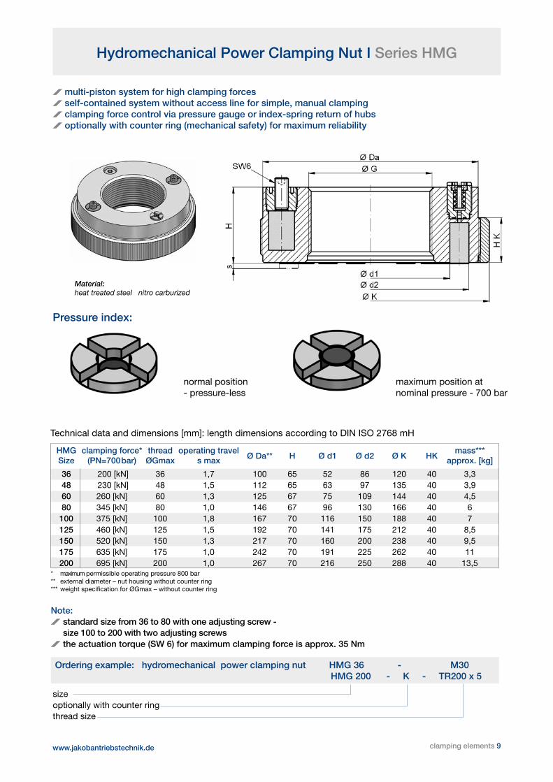
Hydromechanical Power Clamping Nut I Series HMG
multi-piston system for high clamping forces self-contained system without access line for simple, manual clamping clamping force control via pressure gauge or index-spring return of hubs optionally with counter ring (mechanical safety) for maximum reliability
Ordering example: hydromechanical power clamping nut HMG 36 - M30 HMG 200 - K - TR200 x 5
sizeoptionally with counter ring thread size
Material: heat treated steel nitro carburized
Technical data and dimensions [mm]: length dimensions according to DIN ISO 2768 mH
* maximum permissible operating pressure 800 bar** external diameter – nut housing without counter ring*** weight specification for ØGmax – without counter ring
HMG clamping force* thread operating travel mass*** Size (PN=700bar) ØGmax s max Ø Da** H Ø d1 Ø d2 Ø K HK approx. [kg] 36 200 [kN] 36 1,7 100 65 52 86 120 40 3,3 48 230 [kN] 48 1,5 112 65 63 97 135 40 3,9
60 260 [kN] 60 1,3 125 67 75 109 144 40 4,5 80 345 [kN] 80 1,0 146 67 96 130 166 40 6 100 375 [kN] 100 1,8 167 70 116 150 188 40 7 125 460 [kN] 125 1,5 192 70 141 175 212 40 8,5 150 520 [kN] 150 1,3 217 70 160 200 238 40 9,5 175 635 [kN] 175 1,0 242 70 191 225 262 40 11 200 695 [kN] 200 1,0 267 70 216 250 288 40 13,5
Pressure index:
maximum position atnominal pressure - 700 bar
Note: standard size from 36 to 80 with one adjusting screw - size 100 to 200 with two adjusting screws
the actuation torque (SW 6) for maximum clamping force is approx. 35 Nm
normal position- pressure-less
www.jakobantriebstechnik.de
Hydromechanical Power Clamping Nut I General

Hydromechanical Power Clamping Nut I Series HMP
multi-piston system for high clamping forces leak-proof oil refeed into pump and spring return of cylinders high-pressure adapter (axial/radial) for hand- or foot-pump up to 700 bar optionally with counter ring (mechanical safety) for maximum reliability
Technical data and dimensions [mm]: length dimensions according to DIN ISO 2768 mH
* m a x i m u m permissible operating pressure Pmax = 1000 bar ** declaration of weight for Gmax – without counter ring
Ordering example: hydromechanical power clamping nut HMP 100 - M82 x 2 - a HMP 250 - K - TR250 x 5 - a
sizeoptionally with counter ring thread sizeposition of high-pressure adapterstandard version a – axial (optionally s – sidewise or a/s)
Material:heat treated steel nitro carburized
HMP clamping force* thread operating travel mass** Size (PN=700bar) ØGmax s max Ø Da H Ø d1 Ø d2 Ø K HK approx. [kg] 48 290 [kN] 48 8 115 65 66 100 135 40 4,0 60 320 [kN] 60 8 125 65 75 109 144 40 4,5 80 370 [kN] 80 8 146 65 96 130 166 40 6 100 460 [kN] 100 8 167 65 116 150 188 40 7 125 550 [kN] 125 8 192 65 141 175 212 40 8,5 150 640 [kN] 150 8 217 65 160 200 238 40 9,5 175 720 [kN] 175 8 242 65 191 225 262 40 11 200 810 [kN] 200 8 267 70 216 250 288 40 13,5 225 900 [kN] 225 8 292 70 241 275 314 40 15 250 1250 [kN] 250 8 332 75 269 313 353 45 22 275 1380 [kN] 275 8 358 75 294 338 380 45 24 300 1460 [kN] 300 8 382 75 319 363 403 45 26 350 1680 [kN] 350 8 432 75 369 413 454 45 29 400 1900 [kN] 400 8 482 75 419 463 504 45 33
Operating instructions:
The HMP series, by default, has a connection nipple for a user-friendly snap coupling. For longer clamping periods we recommend the usage of a counter ring (“K“). Optionally, a special high-pressure screw-on coupler can be used - this connection nipple features a check valve, the coupler has a lever switch. This allows coupling and decoupling even at maximum hydraulic pressure. The pressurization is maintained throughout the entire clamping process. An additional counter ring maximizes operational safety.
high-pressureadapter
www.jakobantriebstechnik.de 10 clamping elements

clamping elements 11
Hydromechanical Power Clamping Nut I Series HMP-HD
multi-piston system “heavy duty“ - design for highest clamping forces leak-proof oil refeed into pump and spring return of hubs quick-action coupling (axial/radial) for hand- or foot-pump up to 1500 bar with counter ring (mechanical safety) for maximum reliability
www.jakobantriebstechnik.de
Technical data and dimensions [mm]: length dimensions according to DIN ISO 2768 mH
* maximum permissible operating pressure Pmax = 1,500 bar ** weight with Ø Gmax
Ordering example: hydromechanical power clamping nut HMP-HD 250 - TR 250 x 5 - a
sizethread sizeposition of hydraulic clutchstandard version a – axial (optional s – sidewise or a/s)
Material: heat treated steel nitro carburized
HMP-HD clamping force* thread operating travel mass** Size (PN=1200bar) ØG max s max Ø Da H Ø d1 Ø d2 Ø K-1 HK approx. [kg] 60 735 [kN] 60 8 143 90 80 124 168 60 7 80 885 [kN] 80 8 163 90 100 144 190 60 9 100 1030 [kN] 100 8 185 90 121 164 212 60 10,5 125 1180 [kN] 125 8 208 90 145 188 235 60 13 150 1400 [kN] 150 8 236 90 171 215 263 60 14,5 175 1550 [kN] 175 8 257 90 194 238 285 60 17 200 1770 [kN] 200 8 286 90 221 265 314 60 21 225 1920 [kN] 225 8 309 90 245 289 338 60 23 250 2140 [kN] 250 8 338 90 272 316 365 60 34 275 2290 [kN] 275 8 362 100 297 340 390 65 37 300 2510 [kN] 300 8 388 100 323 367 416 65 40 350 2880 [kN] 350 8 438 100 373 417 467 65 44 400 3250 [kN] 400 8 490 100 424 468 518 65 50
Operating instructions:For the clamping process, the HMP-HD series is equipped with a user-friendly quick-action coupling. After pressure build-up and securing with the counter ring, the hydraulic pressure is released. For clamping operati-on, the coupling and cable are separated. For the release process, the hydraulic connection is re-coupled, the pressure is applied, the counter ring is released, and the pressure is released.
high-pressureadapter
Hydromechanical Power Clamping Nut I Series HMP

www.jakobantriebstechnik.de
Hydromechanical Preload Device I HVV-R SeriesRadial Operation - from sides
Hydro-mechanical Preload Device I HVV-A SeriesAxial Operation - from above
12 clamping elements

Mechanical Power Clamping Screw I Series SC
wedge mechanism as force amplifier high clamping forces maximum operational safety low actuation torque simple, manual operation
The power clamping screws of the series SC are equipped with a wedge system as force amplifier. This innovative system allows for highest clamping forces with low ac-tuation torques and simple manual operation. The robust design of all parts, the self-locking mechanism as well as a high overload capability guarantee maximum oper-ational safety. The clamping screws series SC have vari-ous application possibilities, mainly in presses, punches and machine tools, as well as in jigs, fixtures and similar devices.
Function:
The wedge clamping system of the SC clamping screw is self-locking in each clamping position due to its geome-try, and offers a clamping stroke of up to 3 mm. This way, depending on the actuation torque, very high clamping forces up to the nominal clamping force can be achieved.
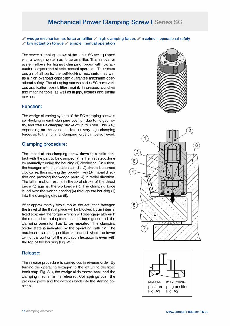
Clamping procedure:
The infeed of the clamping screw down to a solid con-tact with the part to be clamped (7) is the first step, done by manually turning the housing (1) clockwise. Only then, the hexagon of the actuation spindle (2) should be turned clockwise, thus moving the forced-in key (3) in axial direc-tion and pressing the wedge parts (4) in radial direction. The latter motion results in the axial stroke of the thrust piece (5) against the workpiece (7). The clamping force is led over the wedge bearing (6) through the housing (1) into the clamping device (8).
After approximately two turns of the actuation hexagon the travel of the thrust piece will be blocked by an internal fixed stop and the torque wrench will disengage although the required clamping force has not been generated; the clamping operation has to be repeated. The clamping stroke state is indicated by the operating path “s”. The maximum clamping position is reached when the lower cylindrical portion of the actuation hexagon is even with the top of the housing (Fig. A2).
Release:
The release procedure is carried out in reverse order. By turning the operating hexagon to the left up to the fixed back stop (Fig. A1), the wedge slide moves back and the clamping mechanism is released. Coil springs push the pressure piece and the wedges back into the starting po-sition.
releaseposition Fig. A1
max. clam-ping positionFig. A2
14 clamping elements www.jakobantriebstechnik.de

Mechanical Power Clamping Screw I Series SC
Notice:
To ensure the required clamping force is achieved and to protect the internal mechanism from damage, we recommend the use of a torque wrench for applying the actuation torque. Under certain conditions, clamping is also acceptable with a standard wrench or socket wrench.
The clamping screws are lubricated for life and mainte- nance free under normal operating conditions. A high temperature version of up to 400°C is possible.
www.jakobantriebstechnik.de
nominal max. max. max. operating SC clamping actuation clamping static path mass thread force torque stroke load s approx. D* Ø d L1 L SW 1 SW 2 Size [kN] [Nm] [mm] [kN] [mm] [kg]
36 40 40 1,5 80 5 0,5 M 36 x 3 19 62 73 13 30 48 80 80 2,2 160 7,5 1,1 M 48 x 3 28 75 90 17 41 64 140 120 2,5 240 8,5 2,5 M 64 x 4 39 90 110 19 55 80 180 140 2,5 320 8,5 5,3 M 80 x 4 39 100 160 19 65 100 250 130 3 400 17 12 TR 100 x 6 60 205 230 14** 65
*further sizes and threads (inch thread) available on request allowed temperature range: -40°C up to +250°C**hexagon socket - operating pin length: s =17 mm
Technical data and dimensions [mm]: length dimensions according to DIN ISO 2768 mH
Application example:
slide-in-clamp Series MES 3 sizes with up to 100 kN clamping force various possible applications with variable
clamping edge/T-groove sizes: 18/22/28/36 Technical data available on request or on our
homepage: www.jakobantriebstechnik.de
Material:heat treated steel nitro carburized
clamping elements 15

16 clamping elements
Power Clamping Screws I Series MSP/MSPD-HSP
For face plates and surface plates on jaw boxes as well as grinding and turningmachines and special machines
The JAKOB power clamping screws have been devel-oped for the highest demands and maximum workpiece weights with optimum operational safety. They are pri-marily suited for integration in jaw boxes or for direct installation in face plates of lathes, grinding and special machines. Diverse clamping screw series with different constructions and profile requirements are available. The user can choose between hydraulic or mechanical, and single or double actuating designs. All parts are made of heat-treated steel and produced with high precision. This guarantees a clamping element with highest sturdiness and reliability.
Essential features of performance:
enormous clamping force, low actuation torque maximum reliability, high stiffness large clamping stroke, high alignment accuracy simple manual operation minimum maintenance
Double actuating power clamping screw series MSPD 80 for clamping direction internal and external integra-ted in jaw box.
Face plate for turning center with 8 power clamping screws Type MSP 200 for clamping of turbine rotorsup to 350 tons total weight.
Application examples:
www.jakobantriebstechnik.de

Power Clamping Screws I Series MSP/MSPD-HSP
www.jakobantriebstechnik.de
Note:
During calculation of installation length L1 bearing rings or axial washers must be taken into account.
Basically, except the fitting position L1, the thread of the screw housing or the dimensions of the bearing pin can be customised to fit customer needs. That might be necessary, especially when replacing de- fective older model clamping screws and when retrofitting machine tools. Please get in touch with us if you have variances from standard dimensions.
Clamping force monitoring can be integrated using our additionally available Force Monitoring System (FMS). See page 10 for more information.
Operating tools available upon request.
Clamping Force Diagram
Each clamping screw is supplied with a clamping force diagram and a test report.On request, the appropriate clamping force diagram can be supplied on an aluminum plate for fitting to the machine, as available information for the operating personnel. Due to friction loss in the clamping jaws or linear guides, the table or diagram values for the actuation torque must be corrected. The appro-priate factor must be determined, if necessary, by the face plate or jaw box manufacturers either empirically or based on trials and tests.
Mechanical Power Clamping Screw Series MSP / MSPD
The force transmission in the mechanical power clamping screws is generated by a special mechanical key clamping system. The sophisticated geometry of the key mechanics have very large transmission surfaces and a self-locking mechanism to ensure low wear and the highest reliability. Especially worth mentioning is the double-acting version, Series MSPD, with a simple automatic reverser to change clamping direction from external to internal clamping. Furthermore, its simple, manual operation and low installation cost are relevant. When taking the main technical and economic assessment criteria into consideration, the MSP/MSPD Series can be recommended as the ideal version for most applications.
Hydromechanical Power Clamping Screw Series HSP
The hydromechanical power clamping screw‘s operating principle is based on power amplification, resulting from the area ratio of a primary and secondary piston. In the distinctly smaller primary piston, an internal oil pressure of up to 600 bar is generated and at the same time a long stroke distance is travelled. The secondary piston, with its larger effective area with smaller clamping stroke produces an extremely large axial force, which is transmitted through the external thread to the piston housing on the clamping shoe. HSP power clamping screws are only provided for exter-nal clamping direction. They excel with their long clamping strokes and low actuation torques. However, due to the necessary, mechanical safeguard (counter ring), significantly higher expenses are to be expected.
Clamping force diagram “MSPD 120“
(max . static load 600 kN)
exte
rnal
clam
ping
internal clamping
TA±10%
clamping elements 17
18 clamping elements
Mechanical Power Clamping Screws I Series MSP/MSPD
Operation:
External clampingThe clamping jaw is prealigned and pretensioned by turning the external hexagon SW1 clockwise. A torque wrench should be used for force clamping and fine adjustment. By turning the internal hexagon SW2 clockwise, the drive spindle‘s force amplification is activated and clamping force is generated proportionally to the actuation torque until the torque wrench disengages upon reaching the preselected torque (see clamping force diagram). The clamping stroke can be controlled via an operating path indicator. The clamping procedure has to be repeated by loosening SW2 and pretensioning SW1 if the preselected starting torque has not been reached at the end of the operating path. Avoid exceeding the maximum actuating torque as it may cause damage.
Internal clampingThe clamping jaw approaches the workpiece, is prealigned and pretensioned by turning the external hexagon SW1 counter-clockwise. This automatically changes the clamping direction to internal clamping. For this changeover the threaded housing of the power clamping screw with the jaw is maintained in a preloaded state and then sub-jected to an axial motion in reverse direction, i.e. the external hexagon SW1 should be turned by approx. one turn extra. The power clamping with internal hexagon SW2 is then done in a similar manner as the external clamping procedure.
ReleaseRelease is effected in reverse order by turning the internal hexagon SW2 counter-clockwise until the fixed stop. The drive spindle is reversed and the clamping system unclamped. The return spring pushes the threaded spindle with clamping jaw back, the force amplifier returns to its initial position.
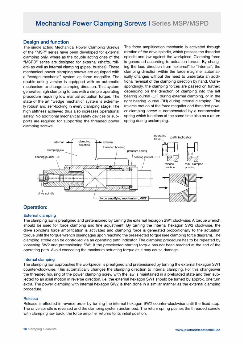
Design and functionThe single acting Mechanical Power Clamping Screws of the “MSP” series have been developed for external clamping only, where as the double acting ones of the “MSPD” series are designed for external (shafts, roll-ers) as well as internal clamping (pipes, bushes). These mechanical power clamping screws are equipped with a “wedge mechanic” system as force magnifier. The double acting version is equipped with an automatic mechanism to change clamping direction. This system generates high clamping forces with a simple operating procedure requiring low manual actuation torque. The state of the art “wedge mechanic” system is extreme-ly robust and self-locking in every clamping stage. The high stiffness achieved thus also increases operational safety. No additional mechanical safety devices or sup-ports are required for supporting the threaded power clamping screws.
The force amplification mechanic is activated through rotation of the drive spindle, which presses the threaded spindle and jaw against the workpiece. Clamping force is generated according to actuation torque. By chang-ing the load direction from “external” to “internal”; the clamping direction within the force magnifier automat-ically changes without the need to undertake an addi-tional reversal of the clamping direction by hand. Corre-spondingly, the clamping forces are passed on further; depending on the direction of clamping into the left bearing journal (LH) during external clamping, or in the right bearing journal (RH) during internal clamping. The reverse motion of the force magnifer and threaded pow-er clamping screw is compensated by a compression spring which functions at the same time also as a return spring during unclamping.
clamping jaw
bearing journal - LH
drive spindle
threaded housing
clampingdirection
pressure spring
bearing journal - RH
operatingtravel
releaseposition
max. clampedposition
externalinternal
path indicator
force amplifying mechanism „MKS“
www.jakobantriebstechnik.de

Mechanical Power Clamping Screws I Series MSP/MSPD
Series MSP - Mechanical Power Clamping Screw for clamping direction “ external ”Series MSPD - Mechanical Power Clamping Screw for clamping directions “ internal and external “
Ordering example: MSPD 100 - TR 100 x 6 - LH - L1 = 300 mm
MSP/MSPD Size 50 65 80 100 120 160 200
ISO-trapezoidal thread TR-left 50x3 65x4 80x5 100x6 120x6 160x8 200x10 nominal clamping force external 100 150 200 250 300 400 500 [kN] internal 70 100 140 180 220 300 400 nominal actuation torque [Nm] 60 80 100 130 160 160 180 max. static load [kN] 150 250 300 400 600 800 1200 stroke h [mm] 2 2,5 3 3 3 3 3 operating travel s [mm] 7,5 15 17 17 17 25 27 hexagon external SW 1 27 41 46 50 55 65 85 internal SW 2 10 12 14 14 17 17 17 a 20 20 20 25 25 30 40 b / c 30 35 40 50 60 70 80 Ø d1/d3 f7 30 45/40 50 60 65 80 100 Ø d2/d4 40 55/52 68 85 95 130 160 MSPD - L1 min. 150 170 230 250 280 330 360 MSPD - L2 min. 230 260 330 375 425 500 560 MSP - L1 min. 140 150 210 220 250 290 320 MSP - L2 min. 220 240 310 345 395 460 520
Technical data and dimensions [mm]: length dimensions according to DIN ISO 2768 mH
Notice: Special thread sizes or customized dimensions are possible upon request. Sizes 120 / 160 / 200 are also available with more powerful clamping force amplifier.
externalinternal
operating travel
left
han
d -
sin
gle
star
tIS
O-
trap
ezoi
dal
thr
ead
Installation length
material:heat treated steel, nitro carburized
clamping elements 19 www.jakobantriebstechnik.de
Mechanical Power Clamping Screws I Series MSP/MSPD

20 clamping elements www.jakobantriebstechnik.de
Hydromechanical Power Clamping Screws I Series HSP
Material:heat treated steel nitro carburized
Note: • after completion of the clamping procedure the clamping screw should be secured against overload by means of a mechanical safety device (counter gearwheel), which as well helps to achieve a high degree of stiffness • special thread sizes or customized dimensions as well as different toothing of counter gear- wheel or series with higher clamping force are available on request • the pinion shaft (SW3) for driving the counter gearwheel is not supplied
HSP size 80 100 120 160 200 220
ISO-trapezoidal thread left TR 80x5 TR 100x6 TR 120x6 TR 160x8 TR 200x10 TR220x10 nominal clamping force [kN] 100 150 220 400 600 750 nominal actuation torque [Nm] 60 70 80 150 150 140 max. static load [kN] 200 300 400 700 1000 1200 stroke h [mm] 3 3 5 6 6 8 operating path s [mm] 16 19 - - - - hexagon external SW 1 46 50 65 75 85 100 internal SW 2 12 14 17 17 17 17 a 20 25 30 35 40 45 b 30 40 50 60 70 70 c 13 15 20 25 30 30 Ø do 71,5 90 108 146 184 201 module m 1,25 1,5 1,5 2 2 3 Ø d1 f7 50 60 75 90 100 120 Ø d2 68 85 100 140 165 180 Ø d3 f7 40 50 60 70 80 100 Ø d4 60 80 90 105 135 150 e 22 25 30 40 45 45 f 15 15 15 20 20 20 g 30 35 40 50 55 60 LG min. 140 145 215 230 300 455 L1 min. 190 200 280 315 395 550
Technical data and dimensions [mm]: length dimensions according to DIN ISO 2768 mH
left
han
d -
sin
gle
star
t
Installation length
external
gearwheel
ISO
- tr
apez
oida
l
Ordering example: HSP 100 - TR 100 x 6 - lh - L1 = 300 mm

The holding force of a clamping device during mechanical tooling is of special importance. It is relevant for tooling quality, but also for the safety of the operator, the workpiece and the machine tool. Especially during the tooling of bigger components with multi-day clamping and numerous shift changes, the monitoring of clamping forces via constant data transfer is safety-relevant. All currently available monitoring systems, no matter whether dynamic or static, cannot capture the readings of the actual clamping situation.
With the intelligent clamping jaw FMS from JAKOB the customer receives a reliable and easy-to-use monitoring system, that constantly transmits the current clamping forces of all jaws telemetrically. The readings can be trans-mitted to the included portable device, to a laptop, or directly to machine control.
If the clamping force during tooling sinks below a threshold set by the customer, a signal is generated immediately, which can be used for emergency shutdown by machine control.
Clamping jaw base body high-strength tempered steel - connection to lower plate slide via screw key for both clamping „inside - outside“ (op-tional: one-piece jaw)
electronics part for evaluation of strain gauge and wireless data transfer including power supply - integrated into jaw‘s backside
load cell with stress gauge
interchangeable pressure piece (soft or hardened)
22 clamping elements www.jakobantriebstechnik.de
FMS - Force Monitoring System

Laptop with USB reception stick portable device with integrated antenna and display
auxiliary antenna for connection to machine control
clamping elements 23
FMS - Force Monitoring System
Functions of the monitoring system:
robust strain gauge load cell measures the clamping force with high accuracy
clamping force readings are sent to an evaluation and sending unit
readings are sent to the portable device, laptop, or machine control wirelessly (WLAN 2,4 GHz)
the readings are evaluated and displayed on the portable device
portable device runs on rechargeable battery which can be recharged using the docking station
docking station can be provided with alarm output optionally
clamping force according to power clamping screws specified to customers needs

General:Hydraulic load cells of the series HMD are robust indicators that calculate axial compressive forces with median accuracy. The force is transferred analogous-ly over pressure pistons and the hydraulic fluid to a manometer with a kN-indicator scale. The measuring system is autarkic, so there is no need of external or additional energy. Therefore static and dynamic forces can be detected at numerous applications of the entirety of mechanical engineering in an easy and economically priced way.
System design - function:The load cells are designed on the basis of the multi-piston-system. The compressive forces are transferred over several small pistons to the hydrau-lic fluid. In the series HMD-R which is in ring forms the pistons are arranged concentrically. The innova-tive principle allows the realization of load cells in ev-ery geometric configuration. The floating piston-over-lay compensates construction and angle mistakes in a considerable dimension. High shearing forces should be avoided. Special piston seals guarantee an enduring and hermetic sealing of the fluid medium.
Notice:During the measuring, ensure that all pistons are pend-ing the measuring surface with the complete pressure load area.
To ensure a flawless measuring function, the manome-ter-connection and the lock or fill screw should not be removed. Load cells are useless for measuring strong pulsating forces or high accelerations.
The inner diameter of the ring load cells is primed for the in-sertion of measuring adapter pieces using four ball latch pins. Customized adapter types are available on request (see exam-ple of use).
24 clamping elements www.jakobantriebstechnik.de
HMD - Hydraulic Force Measuring System
type-size HMD 300-R HMD 600-R
measuring range 0 - 300 kN 0 - 600 kN scale graduation 10 kN 10 kN accuracy [T=20°C] 1,6% 1,0% mass 3,5 kg 6,2 kg temperature range -10°C - +60°C protection class IP 65 maximum piston stroke 1mm

HMD - Hydraulic Force Measuring System

Hydromechanical Spring Clamping Systems I Series ZSF/ZDF
mechanical clamping - hydraulic releasing high operational safety, leak-proof and robust economical clamping solution
General
The hydromechanical spring clamping systems work through interaction of mechanical and hydraulic systems. The clamping force is applied mechanically through a pre-loaded disk spring packet. The two types are provided as spring clamping or spring pressure cylinders. The hydraulic pressure is only required for the release stroke during which the tie rod or thrust pin is lifted. This system guarantees the greatest reliability be-cause the clamping force is maintained fully independent of the oil pressure or leak-losses. With the hydraulic unit‘s short operating times, this system is also cost-effective. The spring clamping cylinders of the ZSF and ZDF series provide sturdy and reliable clamping elements that can be used wherever sliding and movable machine parts need to be temporarily clamped or locked. Other applications are fixture construction and workpiece or tool clamping.
Operational principle
The thrust or draw piston is pressurised reciprocally by the disk spring packet or hydraulic pressure. The spring packet is compressed with increasing oil pres-sure; the spring force increases. Under pressure, the corresponding nominal clamping force is reached as a reaction force of the disk spring packet. To release the thrust or draw piston, a higher hydraulic pressure is required, which, up to a maximum value, is proportional to the release stroke. The setting pressure is required only for precise force adjustment during initial instal-lation. During the actual operating cycle, the cylinders are either pressureless or at release pressure. The corresponding pressure values can be seen in the spreadsheet. In ZSF series spring clamping cylinders, a mandrel or a tie rod is threaded down and secured in the draw piston‘s thread hole (available on request as single piece or with special thread). The draw piston is protected against incorrect installation with a pin connection.
Assembly and adjustment
to operate, a hydraulic unit is needed which should be equipped with a manometer, a pressure cut-off valve, a solenoid valve, and a pressure switch unit.
fill the cylinders and lines at low pressure and bleed (cylinders are supplied unfilled). increase system pressure to the set pressure and maintain; align cylinder using the ring guide nut (ZSF),
setscrews (ZDF-u) or fitting discs (ZDF-o) until the thrust piston or the clamp is free from play; fasten thrust piston with screws or secure the ring guide nut on the clamping cylinder.
release system pressure; set release pressure for the required release stroke; check the release stroke and adjust if necessary.
Note: If automatic clamping operation is not required, the temporary, manual hydraulic connection to a manually operated piston pump with a pressure gauge provides a cost effective alternative (see fig. at left).
slide
machine bed tie anchor withclamping piece
ring-nut
spring clamping cylinder (pull)bleed screw
pressure gauge
hydraulicquick action
hand leverpump
www.jakobantriebstechnik.de 26 clamping elements

Hydromechanical Spring Clamping Systems I Series ZSF/ZDF
clamping elements 27
Spring Clamping Cylinder I Series ZSF
ZSF nominal adjusting max. release release pressure release pressure release pressure stroke volume mass clamping force pressure stroke at 0,5 mm stroke at 1,0 mm stroke at max stroke at 1 mm stroke approx. Size [kN] [bar] [mm] [bar] [bar] [bar] [cm³] [kg]
1.600 16 135 2,0 170 210 290 1,3 2,0 2.500 25 135 1,6 160 185 230 2,0 3,0 4.000 40 150 2,0 170 190 240 2,8 4,5 6.300 63 175 1,5 190 210 235 3,8 6,8 10.000 100 210 1,5 250 280 320 5,0 8,5 16.000 160 210 1,2 240 275 295 7,9 21 20.000 200 210 1,2 240 270 290 11,3 26,5 25.000 250 190 1,6 210 235 260 14,3 41 35.000 350 190 1,0 210 230 230 20,1 60
ZSF Ø D f7 „Version-2“ Ø a Ø b Ø c e f g L M t v adjustment thread
Size Ø D f7 - ring nut
1.600 60 55 85 55 20 40 14 12 101 M 14 x 1,5 24 22 M 58 x 1,5 2.500 70 65 95 65 25 46 14 13 111 M 18 x 1,5 30 23 M 68 x 1,5 4.000 80 75 110 75 30 56 16 12 125 M 22 x 1,5 36 24 M 78 x 1,5 6.300 95 85 125 89 40 67 16 12 135 M 30 x 1,5 48 28 M 92 x 1,5 10.000 105 95 140 100 40 78 16 18,5 150 M 30 x 1,5 50 35 M 102 x 1,5 16.000 142 130 180 137 50 75 32 22 170 M 38 x 1,5 50 50 M 140 x 2 20.000 150 - 190 143 57 92 40 22 200 M 45 x 1,5 60 58 M 148 x 3 25.000 170 - 220 163 70 100 40 22 230 M 45 x 1,5 60 58 M 168 x 3 35.000 200 - 250 192 80 100 45 47 240 M 52 x 1,5 70 65 M 198 x 3
Technical data:
Dimensions [mm]: length dimensions according to DIN ISO 2768 mH
Ordering example: ZSF 25.000 / ZSF 6.300 - 2
Note Version-2: The sizes 1.600 to 10.000 are available alternatively with smaller external diameter “D” cylin-der housing according to column “-2”. Other thread sizes or through holes available on request.
Material:heat-treated steel, burnished
temperature range: -30°C up to +100°C – mounting position: discretionary
bleedscrew
at a
djus
ting
pres
sure
www.jakobantriebstechnik.de

ZDF-o nominal adjusting release pressure release pressure stroke volume mass clamping force pressure at 0,5 mm stroke at 1,0 mm stroke at 1 mm stroke approx. size [kN] [bar] [bar] [bar] [cm³] [kg]
2.500 25 130 160 195 2 3 4.000 40 200 240 280 3 4,4 6.300 63 180 200 225 4 6,0 10.000 100 240 270 300 5 12 16.000 160 205 235 265 8 23 25.000 250 200 220 245 14 35
ZDF-o Ø D Ø a Ø b Ø c Ø e g h L n 2.500 70 95 20 82 6,5 7 75 100 12,5 4.000 80 120 30 100 9 9 85 110 12,5 6.300 90 130 30 110 9 9 95 120 12,5 10.000 115 160 30 140 11 10 120 145 12,5 16.000 150 198 40 175 13 12 130 160 15 25.000 180 230 50 205 13 12 140 170 15
mechanical clamping – hydraulic releasing high operational safety leak-proof and robust temperature range: -30°C up to +100°C mounting position discretionary
Technical data:
Dimensions [mm]: length dimensions according to DIN ISO 2768 mH
Material:heat treated steel, burnished or nitro carburized
Spring Clamping Cylinder I Series ZDF-o
Ordering example: ZDF-o 4.000
www.jakobantriebstechnik.de
Spring Clamping Cylinder I Series ZDF-u
28 clamping elements
clamping elements 29
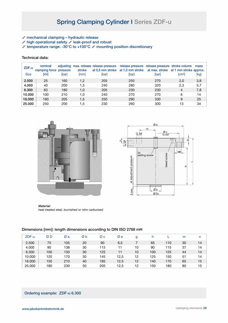
Spring Clamping Cylinder I Series ZDF-u
ZDF-u nominal adjusting max. release release pressure release pressure release pressure stroke volume mass clamping force pressure stroke at 0,5 mm stroke at 1,0 mm stroke at max. stroke at 1 mm stroke approx. Size [kN] [bar] [mm] [bar] [bar] [bar] [cm³] [kg]
2.500 25 160 1,2 205 250 270 2,0 3,8 4.000 40 200 1,5 240 280 320 2,3 5,7 6.300 63 180 1,0 205 230 230 4 7,8 10.000 100 210 1,0 240 270 270 6 14 16.000 160 205 1,5 250 290 330 9 25 25.000 250 200 1,5 230 260 300 13 34
ZDF-u Ø D Ø a Ø b Ø c Ø e g h L m n
2.500 75 105 20 90 6,5 7 85 110 30 14 4.000 90 138 30 115 11 10 90 115 37 14 6.300 100 150 30 125 11 10 100 125 44 14 10.000 120 170 30 145 12,5 12 125 150 51 14 16.000 150 210 40 185 12,5 12 140 170 65 15 25.000 180 230 50 205 12,5 12 150 180 80 15
mechanical clamping – hydraulic release high operational safety leak-proof and robust temperature range: -30°C to +100°C mounting position discretionary
Technical data:
Dimensions [mm]: length dimensions according to DIN ISO 2768 mH
Material: heat treated steel, burnished or nitro carburized
Ordering example: ZDF-u 6.300
ble
ed s
crew
at a
dju
stm
ent
pre
ssur
e
3xsetting screw
www.jakobantriebstechnik.de

Operation Manual - Slide Clamping I ZSF
T-slot screw or tension bolt installation (consider twist lock)
adjust ring nut to mounting position (M) and lock
installation of cylinder, hydraulics -> bleeding of cylinder
load cylinder with adjusting pressure Pa - disk spring package is compressed - T-slot bolt is released by stroke of pressure piston
turn ring nut until ring nut and tensioning bolt are at mechanical stop - lock ring nut with screw
release hydraulic pressure - P = 0 bar - clamping force of disk spring package = FN
load with release pressure PL, disk spring package is compressed further
www.jakobantriebstechnik.de
T-slot bolt and tensioning bolt are in release positi-on. Slide can be moved axially
1. 2.
3. 4.
5. 6.
7. 8.
rele
ase
stro
ke h
L
30 clamping elements

Sectional Rail Couplings

JAKOB Antriebstechnik offers sectional rail couplings that can be used with all current sectional rails. They are attached to existing sectional rails of various brands either directly or via adapter plates, which makes them an excellent choice for retrofitting. They can be disconnected either vertically or horizontally. The patented force amplification via wedge clamping mechanic is able to compensate a gap of up to 5mm between active and passive part. This clamping kinematic ensures high stiffness and precision of the connection. The generation of the clamping force can be achieved either manually by the operating hex head or pneumatically (PN=6 bar). High operational safety is ensured by electrical indication of clamping status and maintaining of minimal clamping force even in case of pressure loss.
Design Layout - Type PKV
Pneumatic Version PKV-P Manual Version PKV-M
Design Layout - Type PKH
Pneumatic Version PKH-P Manual Version PKH-M
Sectional Rail Couplings I Technical Information Sectional Rail Couplings I Technical Information
www.jakobantriebstechnik.de 32 clamping elements

Sectional Rail Couplings I Technical Information
PKV - Design Characteristics
The coupling is comprised of an active and a passive part made from tempered steel. In the active part, the clamping force is gen-erated by a combination of an axially sliding locking bolt and a mechanical clamping gearbox. This design allows for high clamping forces and dynamic stiffness while keeping weight at a minimum. For tool changing, a vertical stroke „K“ (see data sheet) is required.
Type PKV is available in two different versions - the fully automated pneumatically driven PKV-P and the manually operated PKV-M.
PKH - Design Characteristics
The coupling is comprised of an active and a passive part made from tempered steel. In the active part, the clamping force is generated via the use of a vertically sliding clamping pin in combination with the coupling pin in the passive part. This design allows for high clamping forces and dynamic stiffness while mini-mizing weight and clamping times.For tool changing, a horizontal coupling distance „K“ (see data sheet) is required. Type PKH is available in two different versions - the fully automated pneumatically driven PKH-P, as well as the manually operated PKH-M.
Sectional Rail Couplings I Technical Information
Design Characteristics
horizontally or vertically joinable manual or pneumatic clamping high clamping forces through wedge clamping
kinematic high dynamic stiffness - very short clamping times maintained minimal clamping forces even in case of
pressure loss compact dimensions - lightweight electrical indication of clamping status compensation of sectional rail offset of up to ± 5mm high accuracy and repeatability of tool position robust design made from tempered steel –
corrosion-protected pre-centering via centering pin high durability - minimal maintenance costs
clamping elements 33 www.jakobantriebstechnik.de

Technical data and dimensions [mm]: measure of length according to DIN ISO 2768 mH
materials: tempered steel - nitrated
precision ±0,1 mm
Please note: version with customer-specific energy coupling for sup-plying the changing rail with power etc. or different sectional profiles (A x B) on demand.
* operating forces ** bending TA weight couple compen- dimensions [mm]
FB FBmin FQ moment (type M) distance sation width height length bore pattern
type [kN] [kN] [kN] [Nm] [Nm] [kg] K hor. A B C D E
PKH-M-80x80 20 - 25 1000 20 2,7 53 3 80 80 68 4x M8 66
PKH-P-80x80 12,5 3 25 1000 - 2,9 53 3 80 80 80 4x M8 66
PKH-M-100x100 30 - 35 2000 25 4,8 64 4 100 100 81 4x M10 82
PKH-P-100x100 20 4 35 2000 - 5,1 64 4 100 100 93 4x M10 82
PKH-M-120x120 40 - 60 3000 30 7,2 65 4,5 120 120 83 4x M12 100
PKH-P-120x120 30 6,5 60 3000 - 8,7 82 4,5 120 120 115 4x M12 100
PKH-M-140x140 60 - 70 6500 35 10,6 74 5 140 140 94 4x M14 115
PKH-P-140x140 40 10 70 6500 - 12,7 88 5 140 140 128 4x M14 115
PKH-M-160x160 70 - 100 7500 40 15,2 80 5 160 160 105 4x M16 132
PKH-P-160x160 50 11,5 100 7500 - 18,6 109 5 160 160 140 4x M16 132
PKH-M-180x180 80 - 150 13000 50 23 93 6 180 180 122 4x M20 148
PKH-P-180x180 60 14 150 13000 - 26 108 6 180 180 153 4x M20 148
PKH-M-200x200 80 - 150 15000 50 29 95 7 200 200 124 4x M20 168
PKH-P-200x200 75 18,5 150 15000 - 34,7 126 7 200 200 173 4x M20 168
order example: sectional rail coupling PKH - P - 140 x 140 - active part
„P“ - automatic clamping (pneumatic) / „M“ - manual clamping
Size 140 x 140 - sectional profile
active part / passive part
horizontal linear coupling for automatic or manual clamping
* FB - tolerable axial operating force at nominal pressure PN = 6 bar FBmin - minimal operating force at no pressure P=0 bar FQ - tolerable vertical operating force (pressure-independent)
** tolerable operating values M x / y / z at nominal pressure PN=6 bar
manual clamping with operating hex head - top view: TA actuation torque for version „M“
release position clamping position
Sectional Rail Coupling I Type PKH
www.jakobantriebstechnik.de 34 clamping elements

Sectional Rail Coupling I Type PKH
Technical data and dimensions [mm]: measure of length according to DIN ISO 2768 mH
materials: tempered steel - nitrated
precision ±0,1 mm
Please note: version with customer-specific energy coupling for sup-plying the changing rail with power etc. or different sectional profiles (A x B) on demand.
* operating forces ** bending TA weight couple compen- dimensions [mm]
FB FBmin FR FRmin moment (type M) distance sation width height length bore pattern
Type [kN] [kN] [kN] [kN] [Nm] [Nm] [kg] K hor. ver. A B C D E
PKV-M-80x80 20 - 25 - 1000 20 2,5 71 1,5 1,5 80 80 75 4x M8 66
PKV-P-80x80 12,5 3 20 4,5 1000 - 2,6 71 1,5 1,5 80 80 80 4x M8 66
PKV-M-100x100 30 - 35 - 2000 25 4,8 91 2,5 2 100 100 91 4x M10 82
PKV-P-100x100 20 4 30 6 2000 - 4,8 89 2,5 2 100 100 95 4x M10 82
PKV-M-120x120 40 - 60 - 3000 30 8 105 2 2 120 120 109 4x M12 100
PKV-P-120x120 30 6,5 50 10,5 3000 - 8,7 105 2,5 2 120 120 120 4x M12 100
PKV-M-140x140 60 - 80 - 6500 35 12 122 2,5 2,5 140 140 120 4x M14 115
PKV-P-140x140 40 8,5 65 14 6500 - 12 122 3 2,5 140 140 134 4x M14 115
PKV-M-160x160 70 - 100 - 7500 40 18 135 3 2,5 160 160 137 4x M16 132
PKV-P-160x160 50 11 80 17,5 7500 - 18 135 3 2,5 160 160 145 4x M16 132
PKV-M-180x180 80 - 130 - 13000 50 25 154 4 3 180 180 152 4x M20 148
PKV-P-180x180 60 17 100 28 13000 - 26 154 4 3 180 180 164 4x M20 148
PKV-M-200x200 80 - 130 - 15000 50 29 168 4 3 200 200 164 4x M20 168
PKV-P-200x200 75 17 125 28 15000 - 35 168 5 3,5 200 200 184 4x M20 168
order example: sectional rail coupling PKV - P - 140 x 140 - active part
„P“ - automatic clamping (pneumatic) / „M“ - manual clamping
Size 140 x 140 - sectional profile
active part / passive part
manual clamping with operating hex head - top view: TA operation torque for version „M“
release position clamping position
vertical linear coupling for automatic or manual clamping
* FB - tolerable axial operating force at nominal pressure PN = 6 bar FBmin - minimal operating force at no pressure P=0 bar FR - tolerable vertical locking force at PN= 6 bar FRmin - minimal locking force at no pressure P=0 bar
** tolerable operating values M x / y / z at nominal pressure PN=6 bar
Sectional Rail Coupling I Type PKV
clamping elements 35 www.jakobantriebstechnik.de

OTT-Jakob Spanntechnik GmbHIndustriestr. 3-7 · 87663 Lengenwang
Fon: (+49) 83 64 9821 0 · Fax: (+49) 83 64 9821 [email protected] · www.ott-jakob.de
T+S-Jakob GmbH & Co. KGRessestr. 6 · 87459 Pfronten
Fon: (+49) 8363 9125 0 · Fax: (+49) 8363 9125 [email protected] · www.ts-jakob.de
ALLMATIC-Jakob Spannsysteme GmbHJägermühle 10 · 87647 Unterthingau
Fon: (+49) 83 77 929 0 · Fax: (+49) 83 77 929 [email protected] · www.allmatic.de
JAKOB Antriebstechnik GmbHDaimler Ring 42 · 63839 Kleinwallstadt
Fon: (+49) 60 22 2208 0 · Fax: (+49) 60 22 2208 [email protected]
GPA-Jakob Pressenautomation GmbHGreschbachstr. 15 · 76229 KarlsruheFon: (+49) 721 6202 0 · Fax: (+49) 721 6202 [email protected] · www.gpa-jakob.de
OPTIMA Spanntechnik GmbHPostfach 52 · 57584 ScheuerfeldFon: (+49) 2741 9789 0 · Fax: (+49) 2741 9789 [email protected] · www.optima-spanntechnik.de
JAKOB Vakuumtechnik GmbHDaimler Ring 42 · 63839 KleinwallstadtFon: (+49) 60 22 2208 25 · Fax: (+49) 60 22 2208 [email protected] · www.jakobvakuumtechnik.de