the concepts of eurocode 7 for harmonised geotechnical design in...
TRANSCRIPT

1
The Concepts of Eurocode 7 for Harmonised Geotechnical Design
in Europeby
Trevor OrrTrinity College Dublin
at
Politechnika WrocławskaStudia Doktoranckie
on8th to 12th February 2010
2
Day 2
Development of Eurocode 7
GEO & STR ULSs and Design Approaches
Design of Spread Foundations

3
Programme
Special features of soil and Geotechnical Design TriangleAssociated CEN standardsImplementation of Eurocode 7 and future development
5a5b5c
Friday
Risk and reliability in the EurocodesDesign of retaining structuresDesign of slopes and overall stability
4a4b4c
Thursday
Calculation models in Eurocode 7EQU, UPL and HYD ultimate limit statesDesign of pile foundations
3a3b3c
Wednesday
Development of Eurocode 7GEO ultimate limit states and Design ApproachesDesign of spread foundations
2a2b2c
Tuesday
Introduction and background to the Eurocodes and Eurocode 7Basis of design and main features of Eurocode 7Geotechnical data, characteristic parameter values
1a1b1c
Monday
TopicSessionDay

44
Session 2a
Development of Eurocode 7

5
Stages in Development of Eurocode 7
Preparation and publication of national annexesEurocode 7 to supersede European national codes
20072010
Implementation
WG formed to convert ENV into ENEN 1997-1 published by CEN in 2004EN 1997-2 published by CEN in 2007
199920042007
EN stage
WG1 formedProduced Draft EN
19971998
WG1 stage
Trial calculations with ENV and discussions19941996
ENV trial stage
Work began on ENVWork transferred from CEC to CENENV published by CEN
198819901994
ENV stage
Niels Krebs Ovesen appointed chairman of Eurocode 7 committee First EC7 committee meetingModel Eurocode 7 produced
19801981 1987
Model Code stage
Initiative for Eurocodes by universities and engineering professionCEC decided on an action programme for the Eurocodes
19741975
Conception
ActivityYearStage
29 years from 1st committee meeting to implementation

Model Code Stage
1980-87 Preparation of limit state geotechnical design code to serve as a model for Eurocode 7
• Focused on principles• Only a few partial factors proposed
1980 Professor Fukuoka, President ISSMFE, asked Kevin Nash, Secretary General to invite Niels Krebs Ovesen to be Chairman ofEurocode 7 Committee to produce a model code for Eurocode 7
1981 ISSMFE Sub-committee for EC7 formed from 9 EEC countries –first meeting in Brussels
1982 ISSMFE Board considered code work not appropriate so sponsorship withdrawn. Committee became ad-hoc committee
1981-87 Committee met 22 times in different EEC countries to draft code and learn about local geotechnical practices
1987 Committee produced Model Code for Eurocode 7

Simpson (GB), Lousberg (B) Baguelin (F) Japelli (I)Sadgorski (D), Thorp (D) Farrell (IRL) Nelissen (NL)
Orr (IRL) Coumoulos (G) Krebs Ovesen (S) Heijnen (NL)
Dublin Meeting 1983
by Constance Heijnen
8
Model Code Committee 1986
Expanded Eurocode 7 Committee – Portugal 1986

9
Model Code
Chinese translation ofModel Code in 1988
Model Code 1987

10
ENV Stage
1988-97 Preparation of ENV (trial) Eurocode 7Defined characteristic valuePartial factors only on soil strength, not resistanceCases A, B and C with different sets of partial factors
1988 European Commission (CEC) formed a 7-member Drafting Panel for Eurocode 7 with Niels Krebs Ovesen as Chairman
1989 EC decided to transfer Eurocodes to CEN1990 SC7 formed by CEN to oversee work on Eurocode 7
- Niels Krebs Ovesen appointed convenor of SC7- Eurocode 7 given reference number EN 1997
1988-93 Completion of ENV after 22 meetings, mostly in Delft- Adoption of ENV by SC7 and CEN
1994 Publication of ENV by CEN

11
Delft
Canal and Church Tower

12
ENV Trial Stage
1994-96 Trial calculations and discussions about ENV- Some CEN countries not happy with ENV
- Seminar at Institution of Structural Engineers, London Sept-Oct 1996 to discuss ENV
- Some strong views against ENV and partial factors
- EC7 is a very strange document …. On present evidence, it appears that the method proposed in EC7 needs considerably more development before it can be considered for use
- If the present method of EC7 is adopted in this respect it will be a disservice to the industry which will restrain its developmentfor the next decade

13
Eurocode 7 Seminar
London1996

14
WG1 Stage
1997-98 Before starting to transform ENV into an EN, SC7 decided work was needed to make Eurocode 7 more acceptable to geotechnical engineers in Europe
- Introduced three Design Approaches with partial factors on resistances as well as on soil strength
- Introduced sections on failure due to water pressures and seepage
1997 WG1 formed by SC7- To involve all the CEN countries more directly in the
transformation of the ENV into an EN- Ulrich Smoltczyk appointed as convenor- WG1 met 6 times and produced a draft EN
1998 Draft EN produced

15
EN Stage
1999 -2004 Transformation of ENV into EN 1997-1- PT1 established to transform ENV into EN- Ulrich Smoltczyk appointed convenor
2001 Final draft received a unanimous vote of approval from SC7
- Adopted at SC7 meeting in Milan in April- Text translated into 2 other official CEN languages, French
and German
2004 January - Issued to all CEN members for formal voteApril – Positive vote received from all CEN countries- Date of Ratification (DOR)

16
Implementation Stage
2005- present National implementation of EN 1997
2005-07 -Publication of National Annexes for EN 1997-1
2007 - Publication of EN 1997-2- Publication of National Annexes for EN 1997-2- Appointment of a Maintenance Group for EN 1997
2008-09 Corrigenda submitted
2010 31 March: Eurocodes with national annexes to supersede existing national standards
Beginning of Eurocode Era
17
Irish National Standard Version of EN 1997
Irish NA: 2005

1818
• Time for discussion
• Any questions?

19
Tutorial No. 1
Selection of Characteristic Values

20
Problem
• Select characteristic parameter values for design of a spread foundation on sandy soil
• Given CPT data
• Location of boreholes relative to foundation
• Also density of soil

21
Responses Received
• Regarding location of boreholes– Consensus: Not considered significant
– “The results of all four tests show high correlation and little local variation”
• Characteristic values at three depths requested on questionnaire
• Responses for 2m depth
• Characteristic qc value – 17 responses
• How were characteristic values selected:– By eye 32%:– By statistical analysis 27%– By linear regression 23%
• Characteristic qc value: – Minimum value: 10 MPa– Maximum value: 15 MPa– Average value: 13.1 MPa

22
Soil Characteristic Parameters
• Characteristic φ’ value:– Minimum value: 32.7o
– Maximum value: 48.7o
– Average value: 42.0o
• Basis for selection:– φ’ = 13.5 logqc + 23 (from EN 1997-2 and most popular)– φ’ = 29 + √(qc)– φ’ = 28 + 0.14DR (Schmertmann)– φ’ = 16 DR
2 + 0.17DR + 24 (API)
• Characteristic E’ value:– Minimum value: 32 MPa– Maximum value: 70 MPa– Average value: 38.1 MPa
• 81% said they were confident that their design was sound !

23
How do your results compare?

2424
Session 2b
GEO & STR Ultimate Limit States
and
Design Approaches
25
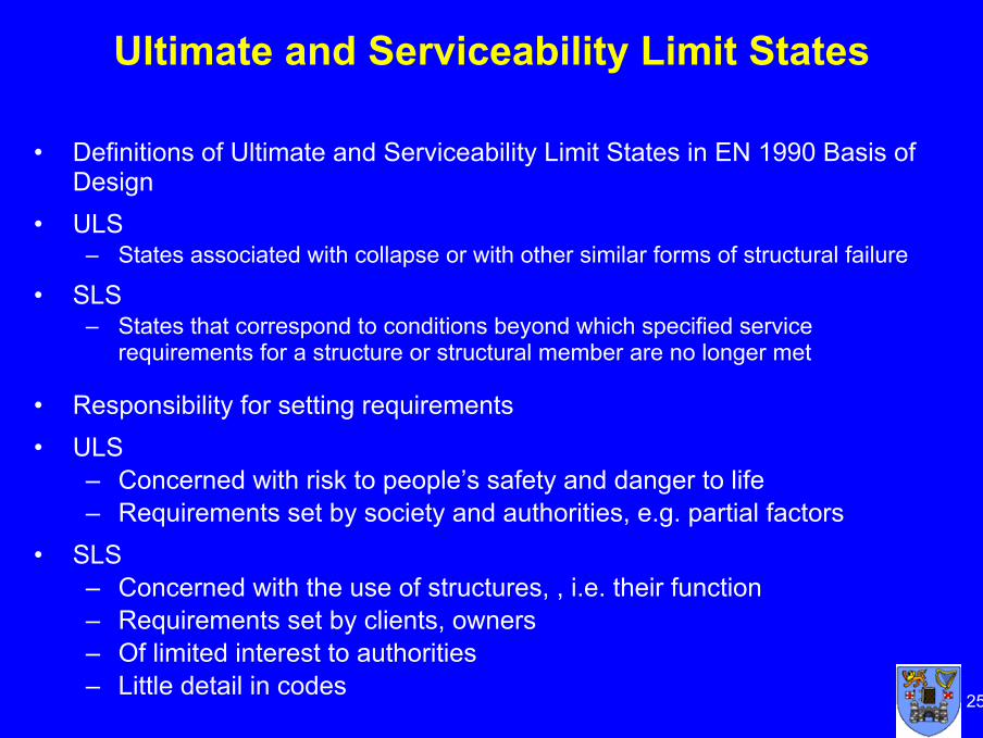
Ultimate and Serviceability Limit States
• Definitions of Ultimate and Serviceability Limit States in EN 1990 Basis of Design
• ULS– States associated with collapse or with other similar forms of structural failure
• SLS– States that correspond to conditions beyond which specified service
requirements for a structure or structural member are no longer met
• Responsibility for setting requirements• ULS
– Concerned with risk to people’s safety and danger to life– Requirements set by society and authorities, e.g. partial factors
• SLS– Concerned with the use of structures, , i.e. their function– Requirements set by clients, owners– Of limited interest to authorities– Little detail in codes

26
GEO & STR Ultimate Limit States
GEO ULS: – Failure or excessive deformation of the ground, in which the strength of
soil of rock is significant in providing resistance
STR ULS:– Internal failure or excessive deformation of the structure or structural
elements, including e.g. footings, piles or basement walls, in which the strength of structural materials is significant in providing resistance
– Partial factors for GEO ultimate limit states are used with STR ultimate limit states
– GEO sometimes gives the loading for STR ultimate limit states
GEO & STR– Hence one set of partial factors in EN 1997-1 are for verification of GEO
and STR ultimate limit states

27
Partial Factors
• For GEO ultimate limit states must satisfy equation Ed < Rd
• Partial factors are applied to either characteristic soil parameters or characteristic resistances to obtain Ed and Rd
• Partial factors are grouped into Sets A, M and R in Annex A– Set A for partial factors on actions or effects of actions– Set M for partial factors on soil parameters– Set R for partial factors on resistances
• Three combinations of sets partial factors are provided in Eurocode 7 for GEO and STR, known as Design Approaches 1, 2 and 3
• Each country has to decide and publish in its National Annex which Design Approach or Approaches are to be used for each type of design– i.e. whether to factor soils parameters or resistances
• Poland has chosen to adopt DA1

28
Design Approaches
• Design Approach 1 (DA1)– Combination 1: Partial factors applied to actions and no partial factors
applied to soil strength parameters (DA1.C1)– Combination 2: Only a reduced partial factor applied to variable actions
and no partial factors applied to soil strengthsExcept for pile foundations, when partial factors are applied to resistances (DA1.C2)
• Design Approach 2 (DA2)Partial factors applied to actions and resistances
• Design Approach 3 (DA3)Partial factors applied to permanent and variable structural actions and to variable geotechnical actions and to soil strength parametersAs DA3 has no resistance factors, not used for pile design

29
Combinations of Partial Factors
Equations given in Eurocode 7 for combining partial factors
DA1 – for most situationsDA1.C1: A1 “+” M1 “+” R1DA1.C2: A2 “+” M2 “+” R1
DA1 – for piles and anchorsDA1.C1: A1 “+” M1 “+” R1DA1.C2: A2 “+” (M1 or M2) “+” R4
DA2A1 “+” M1 “+” R2
DA3(A1* or A2**) “+” M2 “+” R3
* on structural actions** on geotechnical actions

30
Partial Factor ValuesParameter Factor DA1(1) DA1(2) DA2 DA3
Partial factors on actions (γF) or the effects of actions (γE)
Set A1 A2 A1 A1* Struct. Actions
A2 GeotechActions
Permanent unfavourable action γG 1.35 1.00 1.35 1.35 1.00 Permanent favourable action γG 1.00 1.00 1.00 1.00 1.00 Variable unfavourable action γQ 1.50 1.30 1.50 1.50 1.30 Variable favourable action γQ 0 0 0 0 0 Accidental action γA 1.00 1.00 1.00 1.00 1.00
Partial factors for soil parameters (γM) Set M1 M2** M1 M2 Angle of shearing resistance, tanφ' γtanφ' 1.00 1.25 1.00 1.25 Effective cohesion c' γc' 1.00 1.25 1.00 1.25 Undrained shear strength cu γcu 1.00 1.40 1.00 1.40 Unconfined strength qu γqu 1.00 1.40 1.00 1.40 Weight density of ground γ γγ 1.00 1.00 1.00 1.00
Partial resistance factors (γR) Spread foundations and retaining structures Set R1 R4 R2 R3 Bearing resistance γR;v 1.00 1.00 1.40 1.00 Sliding resistance γR;h 1.00 1.00 1.10 1.00 Earth resistance – retaining structures γR;e 1.00 1.00 1.40 1.00 Earth resistance – slopes & overall stability γR;e 1.00 1.00 1.10 1.00
* For slope and overall stability analyses, actions on the soil (e.g. structural actions, traffic loads) are treated as geotechnical actions by using the set of load factors A2
“* M1 is used for calculating design resistances of piles or anchorsM2 for calculating unfavourable design actions on piles owing e.g. to negative skin friction
or transverse loading
31
Comments on DA1
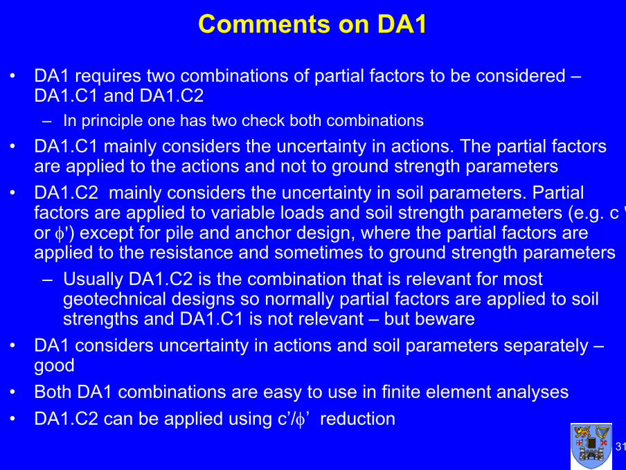
• DA1 requires two combinations of partial factors to be considered –DA1.C1 and DA1.C2 – In principle one has two check both combinations
• DA1.C1 mainly considers the uncertainty in actions. The partial factors are applied to the actions and not to ground strength parameters
• DA1.C2 mainly considers the uncertainty in soil parameters. Partial factors are applied to variable loads and soil strength parameters (e.g. c 'or φ') except for pile and anchor design, where the partial factors are applied to the resistance and sometimes to ground strength parameters– Usually DA1.C2 is the combination that is relevant for most
geotechnical designs so normally partial factors are applied to soil strengths and DA1.C1 is not relevant – but beware
• DA1 considers uncertainty in actions and soil parameters separately –good
• Both DA1 combinations are easy to use in finite element analyses• DA1.C2 can be applied using c’/φ’ reduction

32
Comments on DA2
• Requires only one combination
• Partial factors applied to soil resistances, not to soil parameters
• If DA2 used for slope and overall stability analyses the resulting effect of the actions on the failure surface is multiplied by γE and the shear resistance along the failure surface is divided by γR,e
• Not stated specifically in EC7, but partial factor on action from water pressure is applied to the net water pressure force in DA2
• Closer to more traditional approach
• Difficult to apply in finite element analyses
• Difficult to apply to slope stability analyses using method of slices
33
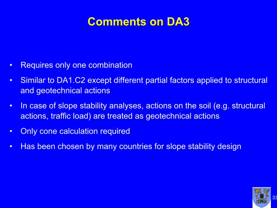
• Requires only one combination
• Similar to DA1.C2 except different partial factors applied to structural and geotechnical actions
• In case of slope stability analyses, actions on the soil (e.g. structural actions, traffic load) are treated as geotechnical actions
• Only cone calculation required
• Has been chosen by many countries for slope stability design
Comments on DA3

34
Bearing capacity or slope stability problem?
What partial factors on foundation loads for DA3?
Bridge Pier

35
Single Source Principle• There is the following important note to Clause 2.4.2 which is
adopted generally in DA1 and DA3:
Unfavourable (or destabilising) and favourable (or stabilising) permanent actions may in some situations be considered as coming from a single source. If they are considered so, a single partial factor may be applied to the sum of these actions or to the sum of their effects
• This is known as the single source principle• Useful in the analyses of slope stability• Difficult to separate
favourable andunfavourable actions
Unfavourable weight
SurchargeFavourable weight
Centre of rotation
Wf
Slip surface
Wu

36
Slope Stability
DA1 and DA3• In a drained analysis of the slope
in the figure, the disturbing force Wsinα and the resisting force, Wcosα are both functions of the weight of the soil element, W
• W is treated as coming from a single source
• In DA1.C1, Wk is factored by 1.35 and tanφ’k is not factored so both Fd and Rd contain 1.35Wd and there is no margin of safety
• Hence DA1.C1 is not relevant• In DA1.C2, Wk is factored by 1.0
and tanφ’k is factored by 1.25 so there is a margin of safety
Wd
Fd = Wdsinα
Wdcosα
DA2• Single source principle not normally
adopted in DA2 so it is often difficult to analyse slope stability since part of soil weight is favourable and part is unfavourable
Rd = Wdsinα tanφ’d
Require:
Fd ≤ Rd

37
Water Pressures on Retaining Structures
Net water pressure (DA2)Total water pressure (DA1 & DA3)
• Not stated specifically in EC7, but partial factor on action from water pressure is applied to the net water pressure force in DA2

38
Design Earth Pressures on a Retaining Wall
• To determine the length of the wall embedment, check the wall stability by taking moments of the design active and passive earth pressure forces, Pa,d and Pp,d, about the tie rod:
Pa,d za = Pp,d zP
• This is a GEO ULS geotechnical design, hence one of the Design Approaches must be selected
• Depending on which Design Approach is adopted, partial factors are either applied to the characteristic actions (earth pressure forces due to permanent and variable loads) or to the characteristicsoil parameters (ck', φk') to give design values Pa,d and Pp,d
Tie rod
Pa,d
Pp,d
zazp
d
• Require the wall embedment depth, d

39
Design Approach 1
DA1.C1• Active and passive earth pressure forces are
both treated as actions• Partial action factors γG = 1.35 and γQ = 1.5
are applied to the characteristic earth pressure forces obtained using unfactored soil strength parameters c’k, φ’k
• For example, if no surcharge– Pa,d = 1.35 Pa,k
– Pp,d = 1.35 Pp,k
• Note: Both Pa and Pp are increased by the same amount
• This combination gives no margin of safety for the embedded length (i.e. for geotechnical design) but is relevant to the structural design of the wall
DA1.C2• Partial action factors γG = 1.0 and γQ
= 1.3 are applied to the earth pressure forces and partial material factors are applied to the soil strength parameters
– c' = c’k/1.4– φd' = tan-1(tanφ’k/1.25)
• Applying partial material factors to reduce c’ and tanφ’ increases Ka and reduces Kp
• Therefore Pa,d > Pa,k
and Pp,d < Pp,k
• This combination gives a margin of safety for the geotechnical design of the embedded length of the wall
• Maximum wall bending moment and shear force DA1.C1 and so is used for but is relevant to the structural design

40
Design Approaches 2 and 3DA2• The active earth pressure force, Pa is
treated as an unfavourable action and the passive earth pressure force, Pp is treated as a resistance
• The design active earth pressure force, Pa,d is obtained by applying partial factors γG = 1.35 and γQ = 1.5 to the unfavourable characteristic active earth pressure force, Pa,k obtained using ck', φk‘
• The design passive earth pressure force, Pp,d is obtained by applying the resistance factor, γR = 1.4 to the characteristic passive earth pressure force, Pa,k obtained using ck', φk‘
• For example, for no surcharge– Pa,d = 1.35 Pa,k
– Pp,d = Pp,k/1.4
• Hence using DA2, the overall factor of safety is 1.35 x 1.4 = 1.89
DA3• DA3 is same as DA1.C2, but γG
= 1.35 and γQ = 1.5 are applied to unfavourable structural actions while γG = 1.0 and γQ = 1.3 are applied to geotechnical actions and partial material factors are applied to reduce soil strength parameters– c’d = c’k/1.4
– φ’d = tan-1 (tan φk'/1.25)

41
Overview of Design Approaches
• Philosophically DA1 and DA3 apply the partial factors close to the source of uncertainty – the soil parameter values
• DA1 looks separately at the uncertainties in the actions and the soil parameter values, which is good
• The DA1 requirement for two separate ULS calculations may discourage some
• Need to be aware that DA1.C1 does not give any safety margin in some design situations – retaining walls and slope stability
• DA1 and DA3 are much easier to use than DA2 in finite element analyses
• DA1.C2 and DA3 can be analysed using c/φ’ reduction• Since the overall factor of safety for DA1 ULS designs, particularly
for undrained conditions, is lower than in traditional designs, the SLS will have more significance in foundation design

4242
Discussion
Any questions?

4343
4
Session 2c
Design of Spread Foundations

44
Design of Spread Foundations
• One of the most common geotechnical design situations is the design of spread (i.e. shallow) foundations
• Term “shallow foundations” not used in Eurocode 7 because of the difficulty in defining the term “shallow”
• Term “bearing resistance” bearing capacity” is used in Eurocode 7 because it is a and involves soil strength
• Hence equation given is called a bearing resistance equation not a bearing capacity equation
• Note that bearing resistance in Eurocode 7 is a force (kN) not a stress (kPa)

45
Limit State Requirements
• Eurocode 7 requires that for each geotechnical design situation it is checked that no relevant limit state is exceeded (Clause 2,1(1))
• The ultimate limit states to be considered in the case of spread foundations are (Clause 6.2(1)):– Loss of overall stability– Bearing resistance failure, punching, squeezing– Failure by sliding– Combined failure in the ground and the structure– Structural failure due to foundation movement
• Since these ultimate limit states are all situations “in which the strength of soil or rock is significant in providing resistance”, according to Eurocode 7 they are GEO ultimate limit states (Clause 2.4.7.1(1))
• The serviceability limit states to be considered are:– Excessive settlements– Excessive heave due to swelling, frost and other causes– Unacceptable vibrations

46
Controlling Limit State
• It is not always obvious which limit state, ultimate or serviceability, controls a design
• Controlling limit state depends on the design situation, i.e. itdepends on:
– Loads
– Soil properties
– Design approach (i.e. chosen partial factors), and
– Allowable deformations

47
Example of a Spread Foundation
0.00
0.50
1.00
1.50
2.00
2.50
3.00
3.50
4.00
0.0 500.0 1000.0 1500.0 2000.0
DA3DA2DA1.C2
Foun
datio
n d
esig
n w
idth
, B(m
)
Characteristic total foundation load, Vk (kN)
SLS
Design controlled by ULS
Design controlled by SLS
In this example• For loads <~ 1000 kN, ULS controls and for loads >~1000 kN, SLS controls• Change occurs at lower loads for DA1 than for DA2 and DA3
• Square pad foundation with vertical central load, Vk = Gk + Qk and Qk = 20% Gk
• Dry soil with φ'k = 35o and Em = 20 MPa

48
Design Methods
• A direct method, in which separate analyses are carried out for each limit state. When checking against an ultimate limit state, the calculation shall model as closely as possible the failure mechanism, which is envisaged. When checking against a serviceability limit state, a settlement calculation shall be used (Clause 6.4(5))
• An indirect method using comparable experience and field or laboratory measurements or observations, chosen in relation to serviceability limit state (i.e. unfactored) loads, so as satisfy the requirements of all relevant limit states
– i.e. one calculation is used to check that neither a ULS nor an SLS occurs
• A prescriptive method in which a presumed bearing resistance is used – No analysis of stability or deformation is carried (Clause 2.5(1)) out but a
presumed bearing resistance is assumed to avoid the occurrence of either a ULS or an SLS
– Only appropriate for Geotechnical Category 1 structures

49
ULS Calculations
• Need to check that Ed ≤ Rd (Clause 2.4.7.3.1(1))– Ed = design action effect = design loads in the case of a foundation = a force– Rd = design resistance and is a force– i.e. the above equation is in terms of forces not stresses– Hence Eurocode 7 is different from traditional design which checks that the
bearing stress does not exceed the allowable stress – Rd is obtained using a calculation model (equation) and the sets of partial
factors for the following Design Approaches:• DA1 - Combination 1
Combination 2• DA2• DA3
– For all Design Approaches, when relevant, need to consider:• Undrained Conditions• Drained Conditions

50
Partial Factor Values
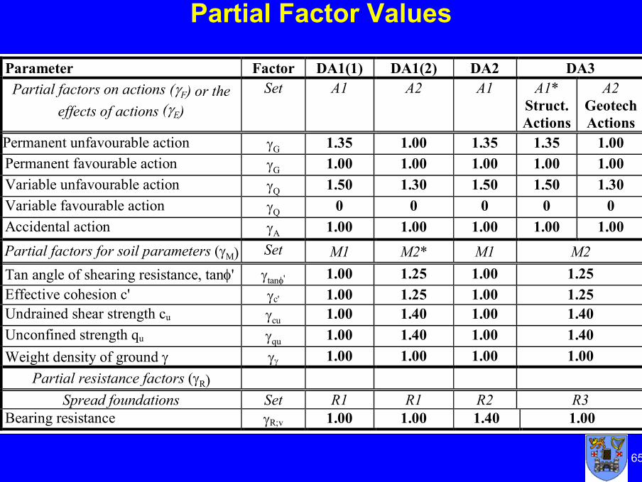
Parameter Factor DA1(1) DA1(2) DA2 DA3 Partial factors on actions (γF) or the
effects of actions (γE) Set A1 A2 A1 A1*
Struct. Actions
A2 GeotechActions
Permanent unfavourable action γG 1.35 1.00 1.35 1.35 1.00 Permanent favourable action γG 1.00 1.00 1.00 1.00 1.00 Variable unfavourable action γQ 1.50 1.30 1.50 1.50 1.30 Variable favourable action γQ 0 0 0 0 0 Accidental action γA 1.00 1.00 1.00 1.00 1.00 Partial factors for soil parameters (γM) Set M1 M2* M1 M2 Tan angle of shearing resistance, tanφ' γtanφ ' 1.00 1.25 1.00 1.25 Effective cohesion c' γc' 1.00 1.25 1.00 1.25 Undrained shear strength cu γcu 1.00 1.40 1.00 1.40 Unconfined strength qu γqu 1.00 1.40 1.00 1.40 Weight density of ground γ γγ 1.00 1.00 1.00 1.00
Partial resistance factors (γR) Spread foundations Set R1 R1 R2 R3
Bearing resistance γR;v 1.00 1.00 1.40 1.00
51
SLS Calculations
SLS calculations
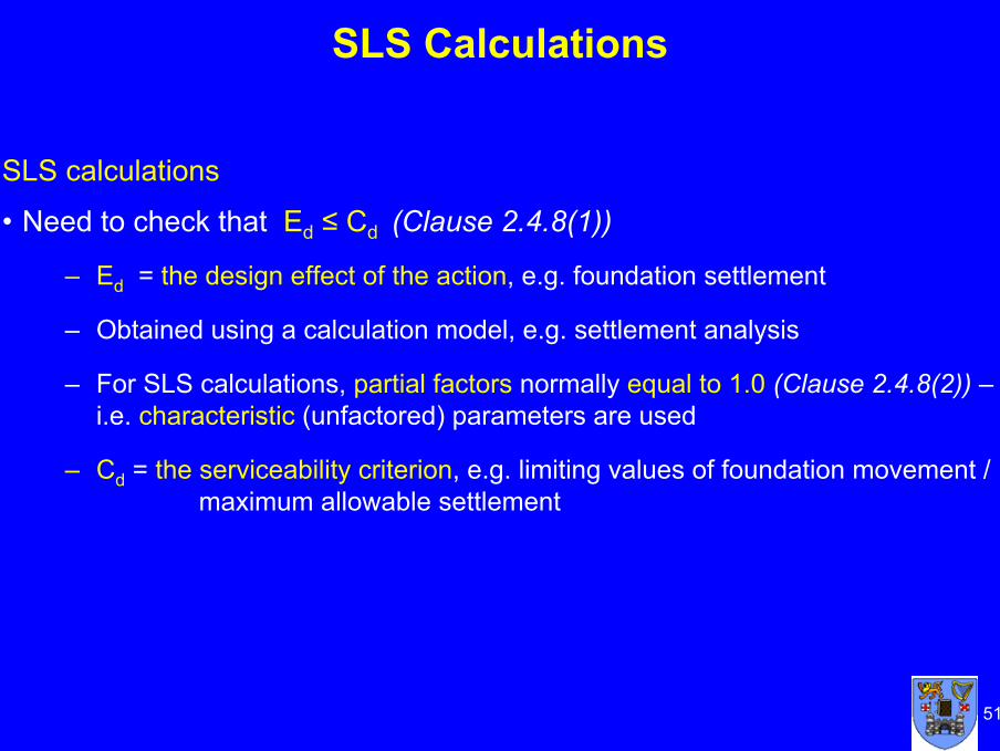
• Need to check that Ed ≤ Cd (Clause 2.4.8(1))
– Ed = the design effect of the action, e.g. foundation settlement
– Obtained using a calculation model, e.g. settlement analysis
– For SLS calculations, partial factors normally equal to 1.0 (Clause 2.4.8(2)) –i.e. characteristic (unfactored) parameters are used
– Cd = the serviceability criterion, e.g. limiting values of foundation movement / maximum allowable settlement

52
Actions and Design Situations(Clauses 2.4.2 and 2.2)
• Main Actions– Permanent and variable loads from the supported structure
• Other actions to be considered– Water pressures
• Note that water pressures may be part of the loading and part of the resistance to determine effective stresses
• Uplift water pressure forces are favourable actions• Need care when applying partial factors to water pressures
– Removal of load or excavation of ground– Soil swelling or shrinkage– Movements due to creeping soil masses– Movements due to self compaction
• Design Situations– Ground water level – major effect on bearing resistance– Drained and undrained conditions – need to check both, where
relevant

53
Design and Construction Considerations
• Eurocode 7 provides a list of factors to be considered (a checklist) when choosing the depth of a spread foundation (Clause 6.4(1)) . These include:– Reaching an adequate bearing stratum– The depth above which damage may occur due to shrinkage or swelling
of clay soils or heave due to frost– The level of the ground water table– Possible ground movements and strength due to seepage, climatic
effects or nearby construction or excavation– Scour– The presence of soluble materials, e.g. karstic limestone

54
Basic Equations and Calculation Models• Ultimate limit state
– Equilibrium equation to be satisfied for bearing resistance or sliding failureEd ≤ Rd
• Serviceability limit state– Serviceability condition to be satisfied
Ed ≤ CdNo calculation models are given in the code text for Rd or Ed
– Only principles are given as to how these should be calculated and how to obtain design values
• Some calculation models for resistance and settlement are given in Annexes D and F
– These are informative annexes, not code text– The national annex for a country must state if the informative annexes are
mandatory or optional– BUT, if you don’t use them your design is not to Eurocode 7!

55
Bearing Resistance Calculation Model
• The model for bearing resistance failure is a rectangular plastic stress block at the limiting stress beneath the foundation, similar to the plastic stress block in the ultimate limit state design of a concrete beam
• The design bearing resistance force, Rd acts through the centre of this stress block over effective foundation area, A’
FV, FH M,
W1W2
Rd
AV
PVd
AH
(from Designers’ Guide to Eurocode 7 by Frank et al.)
Actions and resistance on a spread foundation
A’
Bearing resistance equations (Annex D):
- Undrained conditions: Ru / A’ = (π + 2)cubcscic + q
- Drained conditions: Rd / A’ = c’Ncbcscic + q’Nqbqsqiq + 0.5 γ’B’Nγ bgsgig

56
Settlement Calculations
• Generally a separate settlement calculation is required to check that a serviceability limit state is sufficiently unlikely
• Components of settlement to consider on saturated soils (Clause 6.6.2(2)):– Undrained settlements (due to shear deformation with no volume change)– Consolidation settlements– Creep settlements
• Note words of caution in Eurocode 7 (Clause 6.6.1(6)):“settlement calculations should not be regarded as accurate but as merely
providing an approximate indication”
• Settlement equation (Annex F2: Adjusted elasticity method):s = p × B × f / Em
where:B = foundation widthEm= the design value of the modulus of elasticityf = the settlement coefficient
p = the bearing pressure, linearly distributed on the base of thefoundation

57
Overall Factors of Safety
• For conventional structures founded on clay, one should calculate the ratio, OFSu of the bearing resistance of the ground at its initial undrained shear strength, i.e. at its characteristic (unfactored) cu,k value, to the applied serviceability loading (Clause 6.6.2(16)):
OFSu = Ru,k / Vk
– If OFSu < 3: Settlement calculation should always be undertaken– If OFSiu < 2: Settlement calculation should take account of non-linear
stiffness• This is similar to traditional design where an overall factor of safety of 3 is often
used with an undrained analysis to ensure settlements are acceptable and no settlement calculations are carried out
• However, overall factors of safety of designs for undrained conditions carried out using the Eurocode 7 partial factors are usually much less than 3

58
Overall Factors of Safety for Design Approaches• Examine overall factors of safety for different Design Approaches• Consider a design situation where Vk = 60%Gk + 40%Qk
– DA1.C1, DA2, DA3: Vd = γF Vk = (1.35x0.6 + 1.5x0.4) Vk = 1.41 Vk– DA1.C2: Vd = (1.0x0.6 + 1.3x0.4) Vk = 1.12 Vk– DA1.C1: Ru,d = R (cu,k / γM ) = Ru,k / 1.0 – DA1.C2, DA2, DA3: Rd = R (cu,k/ γM ) or Ru,k/ γR = Ru,k / 1.4
• Design equation is Vd = Rd , i.e. γF Vk = Ru,k/ γR or Ru,k/ γM
• Hence OFSu = Ru, k / Vk = γF x (γM or γR)
1.411.41 x 1.0DA1.C1
1.971.41 x 1.4DA31.971.41 x 1.4DA21.571.12 x 1.4DA1.C2
OFSu = Ru,k / VkγF x (γM or γM )
• All OFSu values < 2.0, hence settlement calculations are required if a Eurocode 7 design is based only on undrained bearing resistance

59
Limiting Values of Foundation Movement
• Eurocode 7 provides limiting values of foundation movement in Annex H• Examples include:
– The maximum acceptable relative rotations (in a sagging mode) for normal routine open framed structures, infilled frames and load bearing or continuous brick walls are unlikely to be the same but are likely to range from about 1/2000 to about 1/300, to prevent the occurrence of an SLS in the structure. A maximum relative rotation of 1/500 is acceptable for many structures
– The relative rotation likely to cause a ULS is about 1/150
– For normal structures with isolated foundations, total settlements up to 50 mm are often acceptable. Larger settlements may be acceptable provided the relative rotations remain within acceptable limits and provided the total settlements do not cause problems with the services entering the structure, or cause tilting etc.

60
Conclusions• Eurocode 7 provides a comprehensive framework with the principles for design
of spread foundations• The designer of spread foundations is explicitly required to:
– Consider all relevant limit states– Consider both ULS and SLS– Consider both drained and undrained conditions (where relevant)– Distinguish between actions on the foundation and resistances– Treat appropriately:
• Forces from supported structure (permanent or variable)• Forces due to water pressure (actions not resistances)
• Since overall factors of safety for ULS design are generally lower than traditionally used for foundation design, it is likely that settlement considerations and hence SLS requirements will control more foundation designs, particularly on cohesive soils and when using DA1
• Eurocode 7 is likely to encourage foundation designers to focus more on SLS considerations

6161
6
Thank you
Discussion
Any questions?

6262
Spread Foundation Design Example

63
Spread Foundation Example
• Design Situation:– Square pad foundation for a building, 0.8m embedment depth; groundwater level
at base of foundation. Central vertical load. Maximum allowable settlement is 25mm.
• Characteristic values of actions:– Permanent vertical load = 900 kN + weight of foundation– Variable vertical load = 600 kN– Concrete weight density = 24 kN/m3.
• Characteristic values of ground properties:– Overconsolidated glacial till, cu,k = 200 kPa, c'k = 0kPa, φ'k = 35o, γk = 22kN/m3
– SPT N = 40• Require foundation width, B
– To satisfy both ULS (drained and undrained conditions) and SLS– Using partial factors values in Irish NA for all Design Approaches
Gk = 900,kN, Qk = 600,kN
GWL
B = ?
d = 0.8 m▼

64
Using Direct Design Method• ULS calculations for 3 Design Approaches
Need to check that Ed ≤ Rd
Since only vertical loads, design action effect = design loads: Ed = Vd
Obtain Rd using the sets of partial factors for the following Design Approaches:– DA1 - Combination 1
Combination 2– DA2– DA3For all Design Approaches need to consider:
• Undrained Conditions• Drained Conditions
• SLS calculationNeed to check that Ed ≤ Cd
Calculate Ed, the action effect, i.e. the settlement, with characteristic (unfactored) parameters
65
Partial Factor Values
Parameter Factor DA1(1) DA1(2) DA2 DA3 Partial factors on actions (γF) or the
effects of actions (γE) Set A1 A2 A1 A1*
Struct. Actions
A2 GeotechActions
Permanent unfavourable action γG 1.35 1.00 1.35 1.35 1.00 Permanent favourable action γG 1.00 1.00 1.00 1.00 1.00 Variable unfavourable action γQ 1.50 1.30 1.50 1.50 1.30 Variable favourable action γQ 0 0 0 0 0 Accidental action γA 1.00 1.00 1.00 1.00 1.00 Partial factors for soil parameters (γM) Set M1 M2* M1 M2 Tan angle of shearing resistance, tanφ' γtanφ' 1.00 1.25 1.00 1.25 Effective cohesion c' γc' 1.00 1.25 1.00 1.25 Undrained shear strength cu γcu 1.00 1.40 1.00 1.40 Unconfined strength qu γqu 1.00 1.40 1.00 1.40 Weight density of ground γ γγ 1.00 1.00 1.00 1.00
Partial resistance factors (γR) Spread foundations Set R1 R1 R2 R3
Bearing resistance γR;v 1.00 1.00 1.40 1.00

66
Undrained ConditionsGeneral Equation for undrained bearing resistance Ru / A’ in Annex D
Ru / A’ = (π + 2) cu bc sc ic + q
To obtain the design undrained bearing resistance Ru,d for all Design Approaches, the relevant partial factors are applied and all parameters are design values:
Ru,d = ( A’ ((π + 2)cu,d bc,d sc,d ic,d + qd )) / γR
where, for undrained conditions, a non-inclined foundation base, a square foundation and vertical loading:
A’ = effective foundation area (reduced area with load acting through its centre) = B2
bc,d = 1.0 sc,d = 1.2 ic,d = 1.0
Substituting known values in Eqn. D.1 and noting qd = γd x d = (γk / γγ ) x d:Ru,d / A’ = ( B2 ( 5.14 x (200 / γcu) x 1.0 x 1.2 x 1.0 + (22 / 1.0) x 0.8) ) / γR
= ( B2 ( 6.17 x 200 / γcu + 17.6 ) ) / γR
General Equation for bearing resistance:
Ru,d = ( B2 (1234.0 / γcu + 17.6) ) /γR

67
Design for DA1.C1Undrained Conditions
Design Approach 1 – Combination 1
Check Vd ≤ Rd for a 1.32 m x 1.32 m pad
Design value of the vertical actionVd = γG(Gk + Gpad;k) + γQQk = γG (Gk + A γcd) + γQQk
where Gpad;k = characteristic weight of the concrete pad, γc = weight density of concrete, A’ = B2 = pad cross-sectional area, d = depth of the pad and γQ = partial factor on variable actions
Substituting values for parameters gives:Vd = 1.35 (900 + 1.322 x 24.0 x 0.8) + 1.5 x 600 = 2160.2 kN
Design value of the bearing resistanceRd = (1.322(1234.0 / γcu + 17.6)) / γR = (1.742(1234.0 / 1.0 + 17.6)) / 1.0
= 2180.8 kN
The ULS design requirement Vd ≤ Rd is fulfilled as 2160.2 kN < 2180.8 kNDA1 = 1.32 m

68
Design for DA1.C2Undrained Conditions
Design Approach 1 – Combination 2
Check Vd ≤ Rd for a 1.39 m x 1.39 m pad
Design value of the vertical actionVd = γG(Gk + Gpad;k) + γQQk = 1.0 (900 + 1.392 x 24.0 x 0.8) + 1.3 x 600 = 1717.1 kN
Design value of the bearing resistanceRd = ( 1.392 (1234.0 / 1.4 + 17.6 ) ) / 1.0 = 1737.0 kN
The ULS design requirement Vd ≤ Rd is fulfilled as 1717.1 kN < 1737.0 kN
DA1 = 1.39 m
Since B = 1.39m for DA1.C2 > B = 1.32m for DA1.C1
DA1 Design Width for Undrained Conditions:
DA1 = 1.39m (given by Combination 2)

69
Designs for DA2Undrained Conditions
Design Approach 2
Check Vd ≤ Rd for a 1.57 m x 1.57 m pad
Design value of the vertical actionVd = γG (Gk + A γcd) + γQQk
Vd = 1.35 (900 + 1.572 x 24.0 x 0.8) + 1.5 x 600 = 2178.1 kN
Design value of the bearing resistanceRd = (1.572(1234.0 / γcu + 17.6 ) ) / γR = (2.465(1234.0 / 1.0 + 17.6)) / 1.4
= 2203.6 kN
The ULS design requirement Vd ≤ Rd is fulfilled as 2178.9 kN < 2203.6 kN.
DA2 Design Width for Undrained Conditions:
DA2 = 1.57 m
70
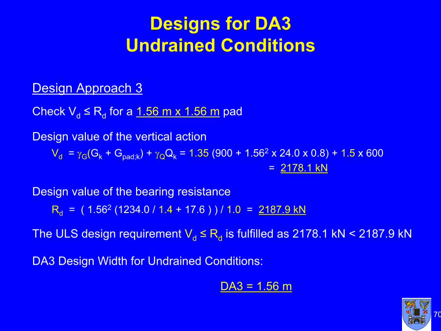
Designs for DA3Undrained Conditions
Design Approach 3
Check Vd ≤ Rd for a 1.56 m x 1.56 m pad
Design value of the vertical actionVd = γG(Gk + Gpad;k) + γQQk = 1.35 (900 + 1.562 x 24.0 x 0.8) + 1.5 x 600
= 2178.1 kN
Design value of the bearing resistanceRd = ( 1.562 (1234.0 / 1.4 + 17.6 ) ) / 1.0 = 2187.9 kN
The ULS design requirement Vd ≤ Rd is fulfilled as 2178.1 kN < 2187.9 kN
DA3 Design Width for Undrained Conditions:
DA3 = 1.56 m

71
General Equation for drained bearing resistance R / A’ in Annex D, Eqn. D.2:Rd / A’ = c’ Nc bc sc ic + q’ Nq bq sq iq + 0.5 γ’ B’ Nγ bγ sγ iγ
In this example the c terms are ignored as c’ = 0.To obtain the design resistance Rd, for all Design Approaches, relevant partial factors are applied and all parameters are design values:
Rd = (A’ (q’dNq,dsq,d + 0.5 γ’dB’Nγ,d sγ,d) ) / γR
where: A’ = effective foundation area = B2
Nq;d = eπtanφ‘d tan2(π/4 + φ‘d/2) Nγ;d = 2 (Nq - 1) tanφ’dsq;d = 1 + sin φ'dsγ;d = 0.7φ'd = tan-1(tan φ'k / γM) = tan-1(tan35/1.25) = 29.3o
Assuming ground water level at ground surface, for γ = 22 kN/m3, γw = 9.81 kN/m3
and since γγ = 1.0:γ’d = (γ - γw ) / γγ = (22.0– 9.81) / 1.0 = 12.19 kN/m3
q’d = γ’dd = 12.19 x 0.8 = 9.75 kPaHence: Rd = (B2 (9.75 Nq,dsq,d + 0.5 x 12.19 B’Nγ,d sγ,d) ) / γR
= (B2 (9.75 Nq,dsq,d + 6.10 B’Nγ,d sγ,d) ) / γR
Drained Conditions

72
Design for DA1.C1Drained Conditions
Design Approach 1 – Combination 1
Check Vd ≤ Rd for a 1.62 m x 1.62 m pad
Design value of the vertical actionVd = γG (Gk + γ’c A d) + γQ Qk
= 1.35 (900 + (24.0 - 9.81) x 1.622 x 0.8 + 1.5 x 600 = 2155.2 kN
Note: Submerged weight of foundation used. Alternatively could use total weight of foundation and subtract uplift force due to water pressure under foundation
Design value of the bearing resistanceRd,d = ( B2 (q’d Nq,dsq,d + 0.5γ’dB’Nγ,d sγ,d)) / γR
= (1.622 (9.75 x 33.3 x 1.57 + 6.10 x 1.62 x 45.23 x 0.7) )/ 1.0 = 2158.2 kN
The ULS design requirement Vd ≤ Rd is fulfilled as 2155.2 kN < 2158.2 kN
DA1.C1 = 1.62 m

73
Design for DA1.C2Drained Conditions
Design Approach 1 – Combination 2
Check Vd ≤ Rd for a 2.08 m x 2.08 m pad
Design value of the vertical actionVd = γG(Gk + γc‘A d) + γQQk
= 1.0 (900 + (24.0 - 9.81) x 2.082 x 0.8) + 1.3 x 600 = 1729.1 kN
Design value of the bearing resistanceRd = 2.082 (9.75 x 16.92 x 1.49 + 6.19 x 2.08 x 17.84 x 0.7) / 1.0 = 1748.4 kN
The ULS design requirement Vd ≤ Rd is fulfilled as 1729.1 kN < 1748.4 kN
B = 2.08m for DA1.C2 > B =1.62m for DA1.C1
DA1.C2 = 2.08 m
DA1 Design Width – Drained Conditions:
DA1 = 2.08m (given by Combination 2)

74
Design for DA2Drained Conditions
Design Approach 2
Check Vd ≤ Rd for a 1.87 m x 1.87 m pad
Design value of the vertical actionVd = γG (Gk + γ’cA d) + γQQk
Vd = 1.35 (900 + (24.0 – 9.81) x 1.872 x 0.8) + 1.5 x 600 = 2168.6 kN
Design value of the bearing resistanceRd = (1.872 (9.75 x 33.3 x 1.57 + 6.10 x 1.87 x 45.23 x 0.7)) / 1.4 = 2174.6 kN
The ULS design requirement Vd ≤ Rd is fulfilled as 2178.6 kN < 2203.6 kN
DA2 Design Width – Drained Conditions:
DA2 = 1.87 m

75
Design for DA3Drained Conditions
Design Approach 3
Check Vd ≤ Rd for a 2.29 m x 2.29 m pad
Design value of the vertical actionVd = γG ( Gk + γc’A d ) + γQ Qk
= 1.35 (900 + (24.0 – 9.81) x 2.292 x 0.8) + 1.5 x 600 = 2195.4 kN
Design value of the bearing resistance
Rd = 2.292 (9.75 x 16.92 x 1.49 + 6.10 x 2.29 x 17.84 x 0.7 ) / 1.0 = 2203.1 kN
The ULS design requirement Vd ≤ Rd is fulfilled as 2195.4 < 2203.1 kN
DA3 Design Width - Undrained Conditions:
DA3 = 2.29m

76
Summary of ULS Designs
2.292.291.56DA3
1.871.871.57DA2
2.082.081.39DA1.C2
(1.62)(1.32)DA1.C1
ULSDesign Width
Drainedwidth (m)
Undrainedwidth (m)
For this example• Drained conditions give the larger design widths
Considering undrained and drained conditions (design width):• DA1.C2 is larger than DA1.C1 • DA3 gives largest width for ULS (2.29m)• DA2 gives smallest width for ULS (1.87m)Considering just undrained conditions:• DA2 gives the largest width for ULS (1.57m)• DA1 gives smallest width for ULS

77
SLS Design
• Is it always necessary to calculate the settlement to check the SLS?
• In SLS Application Rules, Eurocode 7 states that:– For spread foundations on stiff and firm clays … calculations of vertical
displacements (settlements) should usually be undertaken
– For conventional structures founded on clays, the ratio of the bearing capacity of the ground, at its initial undrained shear strength, to the applied serviceability loading (OFSu) should be calculated … If this ratio is less than 3, calculations of settlements should always be undertaken. If the ratio is less than 2, the calculations should take account of non-linear stiffness effects in the ground
• i.e. if OFSu < 3, one should calculate settlement• If OFSu < 2, one should calculate settlement accounting for non-linear stiffness• For undrained designs of foundations with permanent structural loads only
– DA1 give Fi = 1.4 while DA2 and DA3 give Fi = 1.89. Hence settlement calculations are needed

78
OFSu Ratios
Calculating the undrained OFS ratio using the design width – i.e. the drained design width:
OFSu = Ru,k / Vk = A’ ( (p + 2) cu,k bc sc ic + qc ) / Vc= B2 x ( 5.14 x 200 x 1.0 x 1.2 x 1.0 + 20.0 x 0.8) / ( 900 + 600 )= B2 x ( 1234.0 + 16.0 ) / 1500 = 0.833 B
In this example, using design (i.e. drained) widths:• For DA1, OFSu = 3.60 ( > 3 ) Settlement need not be calculated• For DA2, OFSu = 2.91 ( < 3 ) Settlement should be calculated• For DA3, OFSu = 4.37 ( > 3 ) Settlement need not be calculatedBut using the undrained widths OFSu values are all less than 2.0, - much lower than value of 3 often used in traditional designs
1.971.564.372.29DA31.991.572.911.87DA21.571.393.602.08DA1
OFSu using undrained width
= Ru,k / Vk = γF x γM/R
ULS undrained width (m)
OFSu using drained width
= Ru,k / Vk = 0.833 B2
ULS design (drained) width (m)

79
Settlement Calculations
• Components of settlement to consider on saturated soils:– Undrained settlements (due to shear deformation with no volume change)– Consolidation settlements– Creep settlements
• The form of an equation to evaluate the total settlement of a foundation on cohesive or non-cohesive soil using elasticity theory, referred to as the adjusted elasticity method, is given in Annex F:
s = p B f / Emwhere:• Em = design value of the modulus of elasticity• f = settlement coefficient• p = bearing pressure
Assume Em = E’ = 1.5N = 1.5 x 40 = 60 MPa• f = (1 – ν2) I where ν = 0.25 and I = 0.95 for square flexible uniformly loaded foundation• Then f = (1 – 0.252) x 0.95 = 0.891• p = (Gk + Qk)/B2 = (900 + 600) / B2 = 1500 / B2
Hence settlement:• s = p B f / Em = (1500 / B2 ) x B x 0.891 x 1000 / 60000 = 22.28 / B mm
where B is in m

80
Calculated Settlements
9.74.372.29DA3
11.92.911.87DA2
10.73.602.08DA1
Settlement ( mm )s = 22.28 / B
OFSuULS designwidth (m)
• In this example, using adjusted elasticity method and ULS design widths, the calculated settlements, s for all the Design Approaches are less than 25 mm
• The SLS design requirement Ed ≤ Cd is fulfilled as for each DA, s < 25 mm
• Note words of caution in EN 1997-1:Settlement calculations should not be regarded as accurate but as merely providing an approximate indication”

81
Conclusions
In the example considered:
• ULS design: For each Design Approach, the drained condition determines the foundation width
• SLS design: The calculated settlements are less than the allowable settlement of 25mm, so that the SLS condition is satisfied using the design widths obtained using all the Design Approaches
• The ratio Ru,k / Vk for the ULS drained design widths is greater than 3 for DA1 and DA3 so settlement calculations are not required

8282
Thank you for your attention
Discussion
Any questions?