the deepest geothermal well in indonesia: a success story
TRANSCRIPT
GRC Transactions, Vol. 40, 2016
263
The Deepest Geothermal Well in Indonesia: A Success Story of Aerated Drilling Utilization
Apriyansah Toni, Raka Aditya Pratama, Imam M. Prasetyo, and Muhamad Bayu Saputra
PT. Pertamina Geothermal Energy, Menara Cakrawala, Thamrin, JakartaPT. Air Drilling, Menara Sentraya, Iskandarsya, Jakarta
[email protected] • [email protected]
KeywordsLosses, aerated drilling, deepest well, hard formation, geothermal
ABSTRACT
Hululais geothermal field is in the province of Bengkulu, Indonesia. It is one of PT. Pertamina Geothermal Energy (PGE) working areas in Sumatra and has a resource potential of 220 MW (Kamah et.al, 2015). HLS-E1 was drilled to delineate the extent of the resource in the northwest area of the Hululais geothermal field. The well was designed as a large diameter well and the last section was drilled with a 7-7/8” bit and completed with 7” perforated liner which was smoothly landed at the bottom. The total depth is 3203 m measured depth, and is now the deepest geothermal well in Indonesia. During the drilling process, the optimum was achieved from a well-planned program using best practices learned from nearby wells with similar characteristics. Massive losses including partial and total losses, inclination of the well, hard formation, and other issues were the main challenges to drill the well. One of the major factors in the success story is the utilization of aerated drilling in order to miti-gate loss zones. An excellent aerated drilling job requires both experience and engineering design. This well story will be the reference of another well that is now being drilled in the area. By learning and studying from the experience of well HLS E-1, we hopefully can improve the drilling operations in an upcom-ing drilling campaign, in the Hululais area and beyond, in other areas with similar challenges.
1. Introduction
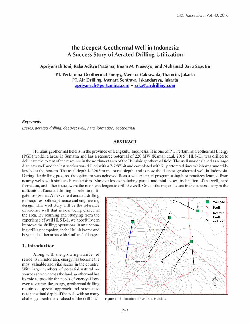
Along with the growing number of residents in Indonesia, energy has become the most valuable and vital sector in the country. With large numbers of potential natural re-sources spread across the land, geothermal has its role to provide the needs of energy. How-ever, to extract the energy, geothermal drilling requires a special approach and practice to reach the final depth of the well with so many challenges each meter ahead of the drill bit. Figure 1. The location of Well E-1, Hululais.

264
Toni, et al.
Hululais geothermal field explora-tion began in 1994 and PGE started the drilling campaign in 2012. With numer-ous wells already drilled in the area, PGE is now drilling more wells in a campaign for the development of a 2 x 55 MW geothermal power plant. Later on the electricity will be distributed to nearby areas on the island.
Well Hululais E-1 was spudded on November 28, 2015 and finished on March 12, 2016. This well was the first drilled in the Hululais area of cluster E (Figure 1). The objective for this well was to delineate the resource area in the northwest area and provide steam to the geothermal powerplant. The reservoir temperature target is about 260-295 °C with benign fluid within the vicinty of Suban Agung Rim.
2. Subsurface
The overall lithology drilled by the well is dominated by a series of andesite lava and pyroclastic rocks. There is also strong evidence that E-1 also cut intrusive diorite within a deep zone of the field based on a borehole image and a core sam-ple. The dominance of intensely fractured andesite lava and the diorite intrusion in the reservoir, play important roles for permeability as well as cuttings pockets for loss circulation during drilling.
The loss zone encountered during drilling started from partial loss circula-tion about 0.3-1.5 BPM at 1670-1798 mMD until the well hit its first total losses at 1799 mMD. Then the fluid sys-tem was switched to aerated drilling with mud down to 1895 mMD where the total loss circulation was encountered again and no gain of returns were realized until total depth at 3203 mMD was reached.
The permeable production zone is shown in Figure 2 as TLC zone and was confirmed by a pressure-temperature
injection survey. It is shown in Figure 3 that the permeable zone started from 1900 mMD to the well bottom. Knowing that the loss rate will be significantly high in each predicted loss circulation zone, it is not an option to
drill ahead with mud only, which can result in poor hole cleaning. In this part aerated drilling can help to enhance the operation by combatting losses and keeping the hole clean.
3. Drilling Challenges
As in any other geothermal operation with highly fractured formation, combatting circulation loss is the biggest drilling problem. It is shown in Table 1 that the loss rates can exceed 20 BPM, which is impossible to maintain because
Figure 2. Composite log of Well E-1.

265
Toni, et al.
the mud cannot be mixed fast enough. Also, by pumping mud into fractured zone the hole an-nulus is not swept clean. This happens because the hydrostatic pressure from the mud is much larger than the formation pressure, hence the mud will go into the fractures but the cuttings are not. The formation in the area is very hard, and both a challenge to penetrate and then to clean out from the bottom. The hard formation produces heavy cuttings therefore cuttings slip velocity is a consideration.
By learning from cases and experiences, the PGE team observed that the key to a successful drilling campaign is using the loss zones for cut-tings storage (“blind drilling”) whenever possible to avoid/minimize the risk of stuck pipe. Using this approach, it is expected that the cuttings can go inside large formation fractures. Hence a mas-sive loss zone is considered the new ’surface’. However, for the smaller fractures where mud can enter the formation but cuttings cannot, proper mitigation is required. Moreover the temperature in the area is considered extreme.
To mitigate loss circulation and associ-ated risks, PGE made a good decision to use the aerated drilling method. The idea of the method is to lower the density of mud while circulating and combating huge fluid losses to the formation by enhancing the annular velocity so the cuttings can be lifted up through the loss zones. And once again, all of this effort is the latest technology to minimize the problem of stuck pipe while drill-ing in highly fractured zones found in geothermal drilling operations.
4. Fundamentals of Aerated Drilling
The main purpose of using aerated drill-ing technology is to combat fluid losses to the formation, which are the biggest contributor to pipe stuck which is caused by the hole packing off. The losses take the fluid from the borehole because the pressure difference from the single-phase fluid and formation is huge. The pressure from the fluid is a function of hydrostatic and pumping rate later on called as ECD (Equivalent Circulating Density). In the aerated method, the ECD is reduced as low as possible to a certain ratio of the gas-liquid volume. This ratio will cause certain fluid flow regime that can be best to be applied in aerated drilling operation.
A small and smooth pattern of bubble flow shown in Figure 4 is the desired regime for aerated drilling fluid. The sizes of bubbles are critical to maintaining the physical the fluid system have and as well bringing the cuttings up to sur-face. On the other hand, large bubbles have a very poor ability to survive in the liquid system.
In nature, hydrostatic pressure decreases to zero at the surface. However in total loss circulation zones, the hydrostatic pressure decreases to zero and at that depth becomes the “new surface”. This phenomenon will lead into further liberation of air from the fluid system in the annulus, hence a substance must be added to mitigate the situation.
Figure 3. PT Survey Under Injection Chart.
Figure 4. Two-Phase Fluid Flow Regime.

266
Toni, et al.
ADA DRILLFOAM, a foaming agent has the ability to strengthen the bond between air and liquid and is a common additive in aerated drilling. The foaming agent will keep the bubbles in suspension and help to carry out the cuttings. Also this chemical has the ability to reduce the interfacial tension so the friction between pipe and formation is reduced.
Prior to utilization, certain tests are mandatory to prove that the foaming agent works. There are two common tests which can be done on site or in the laboratory; the foam height test and half-life time. A mixture of 100 ml water and 1 ml foaming agent will result in a 650 ml foam height after one minute of mixing and can last up to seven minutes in half-life time (Figure 6). Sufficient lifetime of foam is a must due to the ability of the fluid to hold cuttings when circulation stops, for example while making pipe connections.
A common air package consists of three air compressors and one booster (Figure 7). These compressors will suck the air from atmosphere and deliver it to the well. However the discharge pressure from the compressors cannot get into the string because the standpipe pressure is much higher than the compressors. At this point a booster will do the work by increasing the pressure taken from the compressor discharge.
The determination of air usage is based on total fluid rate. As the function of annular velocity, liquid rate gives it parts to hole cleaning. Cuttings and debris produced from drilling activity need to be lifted to get the drill bit goes deeper.
5. Drilling Parameters
Hululais E-1 was planned to 3200 mMD (2658.96 mVD) with the planned hole size configuration of 26″, 17½″, 12¼″, 9⅞″, and 7⅞″ (contingency plan). Several fracture sets were targeted and were produced through perforated 10¾″, 8⅝″, and 7″ casings (Figure 8).
For the surface section, 36″ and 26″ hole, with 30″ and 20″ casing, respectively was drilled smoothly to each cas-ing point. To secure the hole while drilling the 26″ section, a 30″ rotating head was installed on the BOP stack. The 26″ section was drilled with mud from 33mMD to 512 mMD with total loss circulation (TLC) at 46mMD. Loss circulation material (LCM) was pumped down to cure this loss. Another total loss was encountered at 57 mMD and a cement plug was needed to cure the loss circulation. The 20″ casing was successfully set at 511 mMD.
The 17½″ hole section was drilled from 512-1225 mMD with mud. This section was drilled with 800-900 GPM of mud and the results were good. While drilling the 1220-1225 mMD interval, partial losses of 8-9 BPM occurred. A deci-sion was made to drill with air using 1000-1200 SCFM. Another partial loss was found with loss rate 3 BPM. To avoid an excessive cement job for the casing, a cement plug was placed. A 13⅜″ tie back casing was set and cemented at 1215 mMD.
Water Based Mud
Aerated Mud
Foam
Mist
Air, Gas
0 1 2 3 4 5 6 7 8 9Fluid Density, PPG
Figure 5. Geothermal Drilling Fluid Density Range.
Figure 6. Laboratory Test of Foam Agent. Figure 7. An Air Package.

267
Toni, et al.
The 12¼″ hole section was drilled from 1215 mMD depth to 1750 mMD with water-polymer mud. This section was drilled with 750-900 GPM of mud with full returns. But while drilling at 1799 mMD, TLC was encountered (20 BPM). While attempting to circulate the hole, drilling to 1895 mMD continued with aerated mud using 1000-1500 SCFM with full returns. But soon after 1895 mMD was passed, another total loss was found; here the air rate was increased to 1200-1800 SCFM. In this section, 12 GPH of foaming agent and 6 GPH of corrosion inhibitor were used with good results. A 10¾″ perfo-rated liner was set at 2200 mMD.
The 9⅞″ hole section was drilled from 2200 mMD to 2271 mMD depth using 1800 SCFM of air, 10-12 GPH of foaming agent, and 4 GPH of corrosion inhibitor. TLC was encountered but drilling continued to 2499 mMD followed by a wiper trip and survey. After the survey was finished, the drill string was pulled out of the hole with no problems. But while attempt-ing to run back in the hole, the 9⅞″ assembly got stuck at 2450 mMD. After freeing the stuck pipe, the hole was circulated clean and drilled to 2901 mMD. A 8⅝″ perforated liner was set at 2830 mMD.
The 7⅞″ hole section was actually a contingency plan and drilled from 2830 mMD to TD at 3203 mMD. From 2901-2921 mMD, drilling started with 1500 SCFM of air, 610 GPM of mud, 14 GPH of foaming agent, and 4 GPH of corrosion inhibitor. There were no returns due to massive losses. The drilling as-sembly was then pulled out of the well and the bit was replaced with a core bit. After successfully retrieving a core, aerated drilling continued with a 7⅞″ assembly, 1200-1300 SCFM of air, 500-600 GPM of mud 14 GPH of foaming agent, 4 GPH of corrosion inhibitor to TD. A 7″ perforated liner was set on bottom at 3203 mMD. The well TD is now the deepest geothermal well in Indonesia.
Average ROP, torque and standpipe pressure (SPP) in Table 1 shows that the drilling operation for each section was mostly smooth and fast even with loss circulation interval.
Table1. Summary of Actual Drilling Parameter.
Hole Section ROP, Min/M
Fluid, GPM Air, SCFM Air Ratio
Foam, GPH
Loss Rate (BPM)
Torque, KlbFt
SPPPSI
17½″ 13.6 800-930 1000-1200 9.3 - 9.6 - 0.5 – 8.7 6.7 1480
12¼″ 10 650-850 1000-2000 11.5 - 17.6 12 0.3 - >20 10.9 1502
9⅞″ 11.9 650-850 1800-2000 20 - 17.6 14-16 > 20 18.3 1360
7⅞″ 7.9 470-550 1200-1500 19.1 - 20 16-18 > 20 12 515
Figure 8. Well Schematic: Plan vs Actual.

268
Toni, et al.
Conclusion
The success story of well HLS E-1 is proof that the utilization of aerated drilling to TD is effective. The lessons learned from this well can be applied as a base line for the success of the next drilling campaign. By implementing proper engineering design, operational experiences, and excellent chemicals (foaming agent and corrosion inhibitor), we are confident in drilling deep, or even deeper wells in other locations with similar challenges in future drilling campaigns. How-ever advance improvement and development are required to increase the efficiency of the drilling campaign in the future.
ReferencesLyons, W. C., Guo, B., Graham, R. L., and Hawley, G. D., 2009. Air and Gas Drilling Manual: Applications for Oil and Gas Recovery Wells and
Geothermal Fluids Recovery Wells. Burlington: Elseiver.
Dwinanto, Ariya, and Rachmat, Sudjati, 2014. Aerated Underbalance Drilling Screening Assessment at “X” Geothermal Field in Indonesia. Stanford University, California, USA.
Ashadi, and Dumrongthai, Panurach, 2015. Successful Implementation of Aerated Drilling in Improving Geothermal Drilling Performance. Proceed-ings World Geothermal Congress 2015 Melbourne, Australia.
Kesuma Adi Putra, I. M., 2008. Drilling Practice With Aerated Drilling Fluid: Indonesian and Icelandic Geothermal Fields. UNU-GTP, Iceland.
F. Sarmiento, Zosimo, and Thorhallsson, Sverrir., 2011. Directional And Air Drilling Techniques. UNU-GTP and LaGeo, in San Tecla, El Salvador.
Hole, Hagen, 2008. Drilling Fluids For Drilling of Geothermal Wells. Petroleum Engineering Summer School, Dubrovnik, Croatia.
APPENDIX
Figure 9. Aerated Drilling Decision Tree.

269
Toni, et al.
Figure 10. Chart Gross Permeability Test and Fall Off Test.
Figure 11. Pump Rate vs Pwf.

270
Toni, et al.
Figure 12. Well Trajectory.
Figure 13. Well HLS E-1 Drilling Time.