the delay-friendliness of tcpelibrosh/sigmet-votcp.pdfcontributions l a discrete-time markov model...
TRANSCRIPT
The Delay-Friendliness of TCP
Eli Brosh, Salman Baset, Dan Rubenstein, Henning SchulzrinneDan Rubenstein, Henning Schulzrinne
SIGMETRICS 2008
Motivation
l TCP is not designed for real-time applications
– Provides reliable, in-order delivery: not needed by real-time applications
June 08 The Delay-Friendliness of TCP2
applications
– Delay is not primary concern
l Motivated design of unreliable protocol alternatives
– RTP, DCCP, TFRC, and others
Motivation
l Despite its shortcomings, TCP is widely used by commercial real-time systems
– Skype and Windows Media Services support TCP
June 08 The Delay-Friendliness of TCP3
l Majority of streaming traffic uses TCP [SMZ04,GCXZ05]
– UDP packets are blocked by many NATs and firewalls
– A mature, standardized, widely-used protocol
We answer the question of when and why TCP
works for real-time transmission
Contributions
l A discrete-time Markov model for the delay distribution
of TCP
June 08 The Delay-Friendliness of TCP4
l Quantify the feasible region of TCP for VoIP and live
video streaming
– Insight: packet sizes play an important role in determining feasible region
l Provide application-level heuristics for reducing delay
– Also, socket and system-level delay-friendly TCP settings
Related Work
l Extensive literature on TCP modeling and analysis
– Model the performance of file transfers [PFTK98,CSA00,..] and video
streaming [WKST04,KA06] from the standpoint of throughput not delay
June 08 The Delay-Friendliness of TCP5
l Kernel-level enhancements for reducing TCP delays
– Adapting TCP send buffer size [GKLW02]
– Eliminating reliability [MLWL05, MB00]
l Application-level schemes for reducing TCP delays
– Focuses on interactive apps such as telnet and games [GH06, MK07]
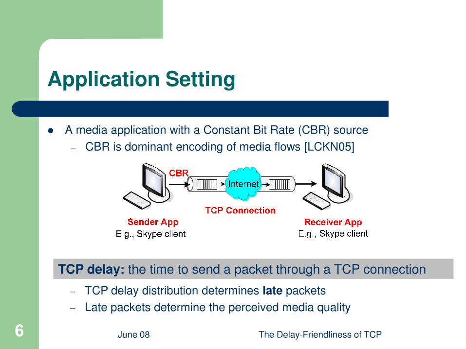
Application Setting
l A media application with a Constant Bit Rate (CBR) source
– CBR is dominant encoding of media flows [LCKN05]
June 08 The Delay-Friendliness of TCP6
TCP delay: the time to send a packet through a TCP connection
– TCP delay distribution determines late packets
– Late packets determine the perceived media quality
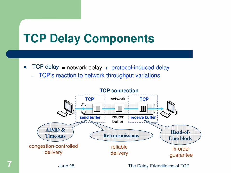
TCP Delay Components
l TCP delayl TCP delay = network delay + protocol-induced delay
– TCP’s reaction to network throughput variations
June 08 The Delay-Friendliness of TCP7
network
router buffer
TCP
send buffer receive buffer
AIMD &
Timeouts
TCP
TCP connection
congestion-controlled
delivery
Retransmissions
reliable
delivery
Head-of-
Line block
in-order
guarantee
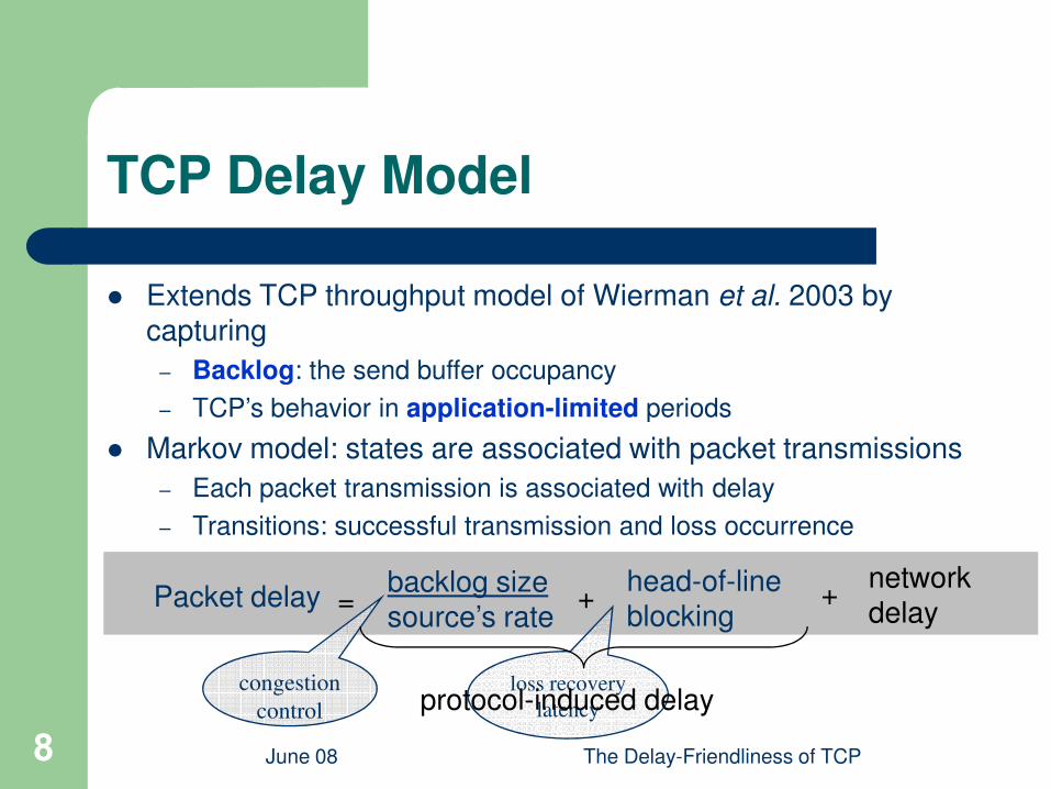
TCP Delay Model
l Extends TCP throughput model of Wierman et al. 2003 by capturing
– Backlog: the send buffer occupancy
TCP’s behavior in application-limited periods
June 08 The Delay-Friendliness of TCP8
Packet delaybacklog sizesource’s rate
head-of-lineblocking
= +
congestion
control
loss recovery
latency
– TCP’s behavior in application-limited periods
l Markov model: states are associated with packet transmissions
– Each packet transmission is associated with delay
– Transitions: successful transmission and loss occurrence
networkdelay
+
protocol-induced delay
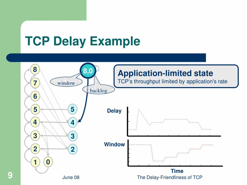
TCP Delay Example
6
7
8 8,0
window
Application-limited stateTCP’s throughput limited by application's rate
backlog
June 08 The Delay-Friendliness of TCP9
1
2
3
4
5
6
0
Time
Window
Delay5
2
3
4
backlog
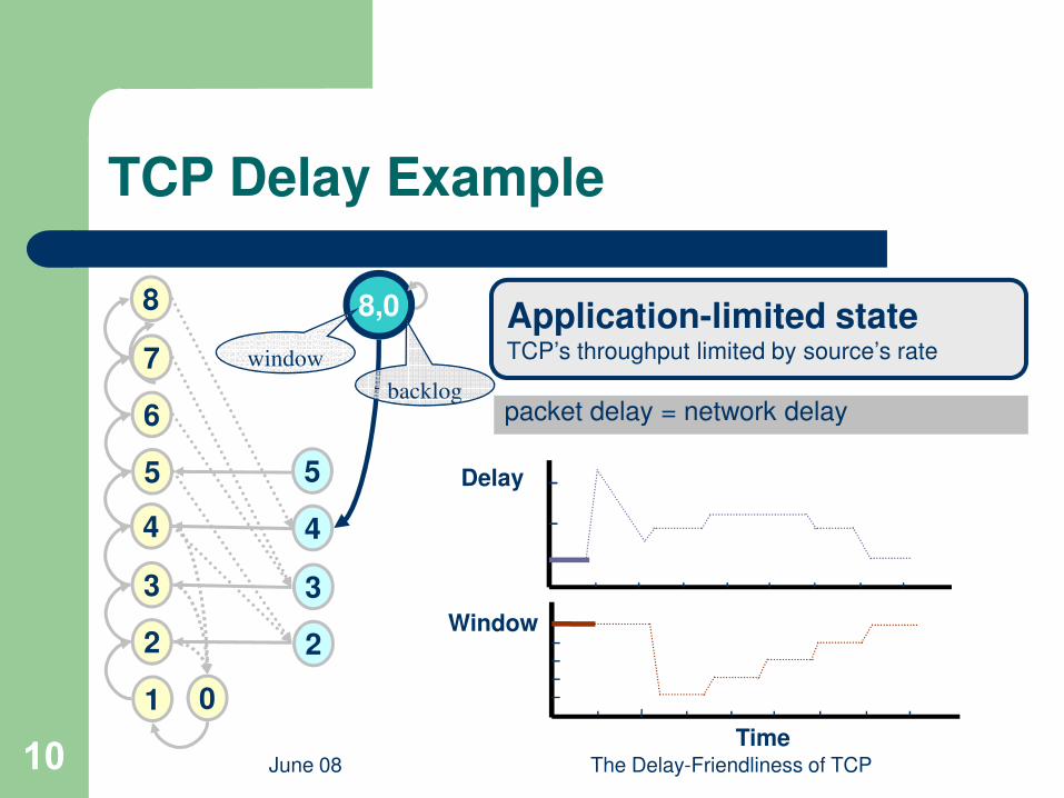
TCP Delay Example
6
7
8 8,0
window
backlog
Application-limited stateTCP’s throughput limited by source’s rate
packet delay = network delay
June 08 The Delay-Friendliness of TCP10
1
2
3
4
5
6
0
Time
Window
Delay5
2
3
4
backlogpacket delay = network delay
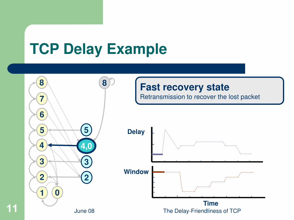
TCP Delay Example
6
7
8 8Fast recovery stateRetransmission to recover the lost packet
June 08 The Delay-Friendliness of TCP11
1
2
3
4
5
6
0
Time
Window
Delay5
2
3
4,0
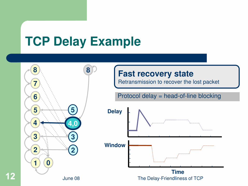
TCP Delay Example
6
7
8 8Fast recovery stateRetransmission to recover the lost packet
Protocol delay = head-of-line blocking
June 08 The Delay-Friendliness of TCP12
1
2
3
4
5
6
0
Time
Window
Delay5
2
3
4,0
Protocol delay = head-of-line blocking
TCP Delay Example
6
7
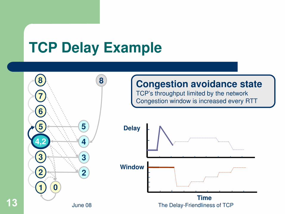
8 8 Congestion avoidance stateTCP’s throughput limited by the network
Congestion window is increased every RTT
June 08 The Delay-Friendliness of TCP13
1
2
3
4
5
6
0
Time
Window
Delay5
2
3
44,2
TCP Delay Example
6
7
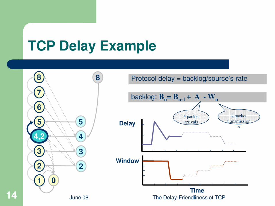
8 8 Protocol delay = backlog/source’s rate
backlog: Bn= B
n-1 + A - W
n
June 08 The Delay-Friendliness of TCP14
1
2
3
4
5
6
0
Time
Window
Delay5
2
3
44,2
# packet
arrivals
# packet
transmission
s
TCP Delay Example
6
7
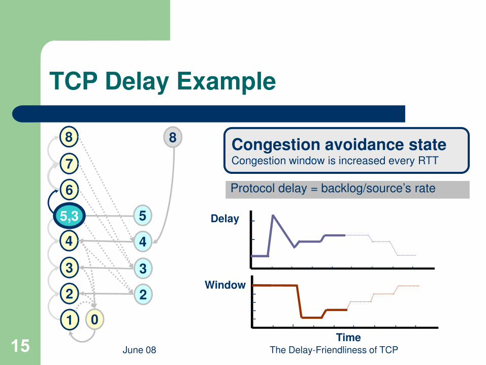
8 8Congestion avoidance stateCongestion window is increased every RTT
Protocol delay = backlog/source’s rate
June 08 The Delay-Friendliness of TCP15
1
2
3
4
5
6
0
Time
Window
Delay5
2
3
4
5,3
Protocol delay = backlog/source’s rate

TCP Delay Example
6
7
8 8
6,3
Congestion avoidance stateCongestion window is increased every RTT
Protocol delay = backlog/source’s rate
June 08 The Delay-Friendliness of TCP16
1
2
3
4
5
6
0
Time
Window
Delay5
2
3
4
6,3 Protocol delay = backlog/source’s rate

TCP Delay Example
6
7
8 8
7,2
Congestion avoidance stateCongestion window is increased every RTT
Protocol delay = backlog/source’s rate
June 08 The Delay-Friendliness of TCP17
1
2
3
4
5
6
0
Time
Window
Delay5
2
3
4
Protocol delay = backlog/source’s rate
TCP Delay Example
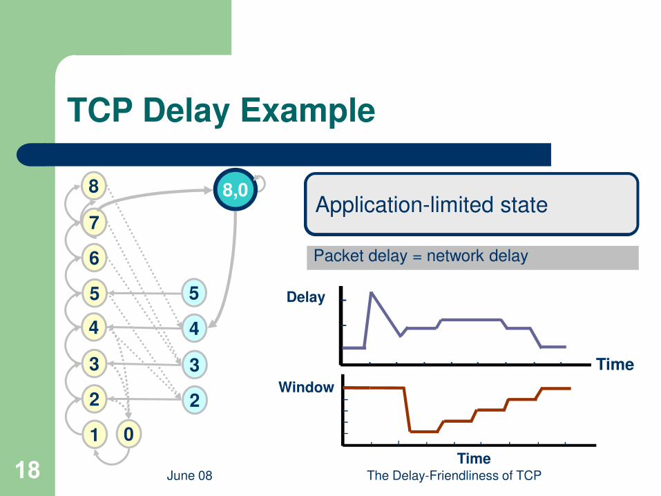
Application-limited stateTCP’s throughput limited by source’s rate
Packet delay = network delay6
7
8 8,0Application-limited state
June 08 The Delay-Friendliness of TCP18Time
Window
Delay
Packet delay = network delay
1
2
3
4
5
6
0
5
2
3
4
Time

Model Validation Settings
l Controlled environment– Drop-tail bottleneck router
l Loss rates: 0.1% -10%, RTTs: 20-300ms
June 08 The Delay-Friendliness of TCP20
l Internet experiments– Planet Lab and residential machines
Interne
t clou
dInternet
Bottleneck buffer

Validation Using Internet Experiments
0.6
0.8
1
95%
model dela
y (
s) calif, RTT=76ms,p=2.68%
japan,RTT=208ms,p=0.87%taiwan,RTT=220ms,p=0.54%calif,RTT=86ms,p=1%calif,RTT=86ms,p=0.5%
June 08 The Delay-Friendliness of TCP21
l Good match for Internet experiments andcontrolled environment
– Prediction error ≤ 25%
0 0.5 10
0.2
0.4
0.6
95% measurement delay (s)
95%
model dela
y (
s)
calif,RTT=86ms,p=0.5%italy,RTT=117ms,p=0.5%china,RTT=239ms,p=0.1%germany,RTT=104ms,p=0.1%

When Does TCP Work?
l Voice over IP (VoIP) application
Packet size 160 bytes300
June 08 The Delay-Friendliness of TCP22
Packet size 160 bytes
Bit rate 64 kb/s
Delay tolerance < 200ms
0
0.2
0.4
0.6
0.8
1
2 4 6 8 10
50
100
150
200
250
packet loss rate (%)
roun
d trip
-tim
e (
ms)
Feasible
region
Feasible region:
RTT≤100ms, Loss≤2%
delay (s)

5300
When Does TCP Work?
l Live video streaming application
Packet size 1400 bytes
June 08 The Delay-Friendliness of TCP23
0
1
2
3
4
2 4 6 8 10
50
100
150
200
250
packet loss rate (%)
round tri
p-t
ime (
ms)
Packet size 1400 bytes
Bit rate 573 kb/s
Delay tolerance ≈ 5s
Feasible
region
Feasible region:
RTT≤200ms, Loss≤3%
delay (s)
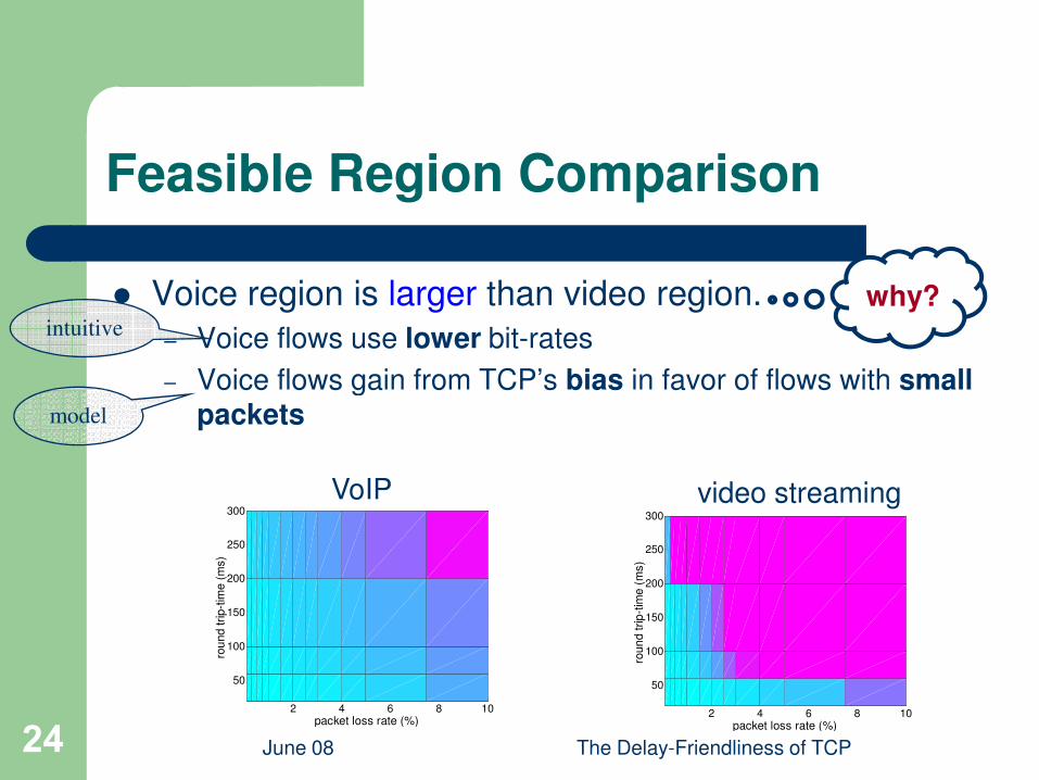
Feasible Region Comparison
l Voice region is larger than video region.
– Voice flows use lower bit-rates
– Voice flows gain from TCP’s bias in favor of flows with small
why?intuitive
June 08 The Delay-Friendliness of TCP24
– Voice flows gain from TCP’s bias in favor of flows with smallpackets
2 4 6 8 10
50
100
150
200
250
300
packet loss rate (%)
rou
nd tri
p-t
ime (
ms)
2 4 6 8 10
50
100
150
200
250
300
packet loss rate (%)
roun
d trip
-tim
e (
ms)
VoIP video streaming
model

The Effect of Packet Size on Delay (1)
l Most TCP implementations use packet-based
congestion control (ACK-counting)
– TCP regulates rate based on number of sent packets
June 08 The Delay-Friendliness of TCP25
– TCP regulates rate based on number of sent packets
– Magnitude of rate fluctuations (in bytes) is smaller for flows with small packets
Bias in favor of flows with small packets (e.g., VoIP)
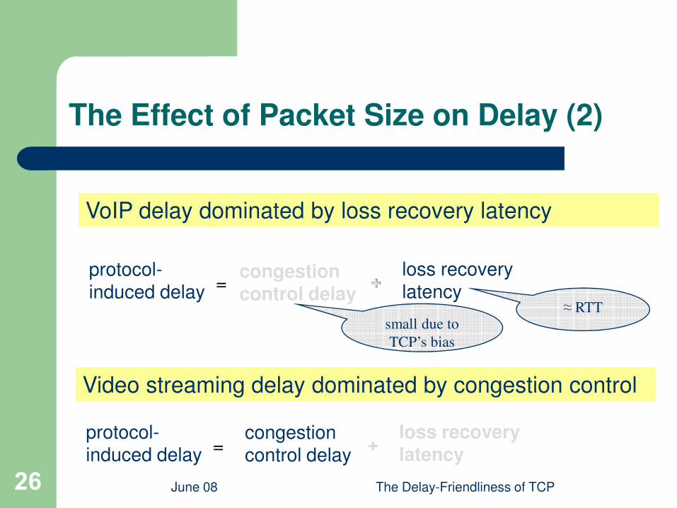
The Effect of Packet Size on Delay (2)
VoIP delay dominated by loss recovery latency
June 08 The Delay-Friendliness of TCP26
= +loss recoverylatency
protocol-induced delay
small due to
TCP’s bias
Video streaming delay dominated by congestion control
= +congestion control delay
loss recoverylatency
protocol-induced delay
≈ RTT
+congestion control delay
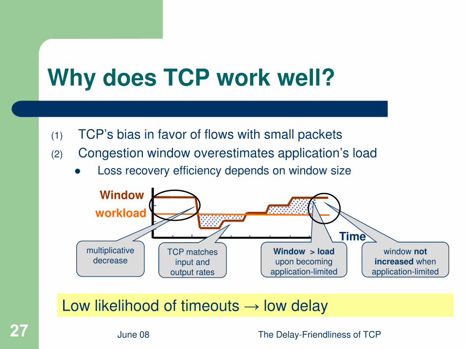
Why does TCP work well?
(1) TCP’s bias in favor of flows with small packets
(2) Congestion window overestimates application’s load
l Loss recovery efficiency depends on window size
June 08 The Delay-Friendliness of TCP27
l Loss recovery efficiency depends on window size
Low likelihood of timeouts → low delay
Window
workload
Timemultiplicative
decreaseTCP matches
input and
output rates
window not
increased when
application-limited
Window > load
upon becoming
application-limited
Application-level Heuristics for Reducing TCP Delay
l Packet splitting– Exploits TCP’s bias in favor of small packet flows
– Masquerades a flow with large packets as one with small packets
June 08 The Delay-Friendliness of TCP28
packets
l Parallel Connections– Stripe load across multiple connections
l Effective for video streaming but ineffective for VoIP– Parallel connections outperforms packet splitting in terms of
performance and fairness
Conclusions
l Demonstrate why real-time traffic over TCP is feasible
in today’s Internet
June 08 The Delay-Friendliness of TCP29
l Feasible region of TCP for VoIP is larger than that for
video streaming
– As long as packet-based congestion control is enforced
l Parallel connections has better performance and is
more fair than packet splitting

Thanks you!
Questions?
June 08 The Delay-Friendliness of TCP30
Questions?