the demonstrations & science experiment...
TRANSCRIPT

Gregory Ginet, MIT/LL
Michael Starks, AFRL
Bob Johnston, AFRL
Jay Albert, AFRL
The Demonstrations & Science
Experiment (DSX)
Radiation Belt Storm Probes
Science Working Group
31 Aug 2010

PROPULSION
DIRECTORATE
Space Environmental
Effects
VLF Wave-Particle Interaction
Experiment
Space Weather
Experiments
Spacecraft Bus
Launch SegmentProgram Office
Systems Engineering
Integration and Test
DSX The Team

DSX Outline
• Introduction
• DSX experimental payloads
• Science question – where is the 20 dB?
• Science question – how efficient are antennas in a plasma?
• Engineering requirement – mapping MEO
• Summary

DSX Mission Objectives
Three science experiments:
1) Wave-particle interactions (WPIx)
• Determine efficiency of injecting VLF into space
plasmas in situ
• Determine global distribution of natural & man-made
ELF-VLF waves
• Characterize and quantify wave-particle interactions
2) Space weather (SWx)
• Map MEO radiation & plasma environment
• Diagnose in-situ environment for wave generation
experiments
3) Space environment effects (SFx)
• Quantify effects of MEO environment on new
technologies
• Determine physical mechanisms responsible for
material breakdown
6000 x 12000 km, 120,
launch ~ Oct 2012
Magnetic phase space
L*
Eq
ua
tori
al p
itc
h-a
ng
le

Wave-Particle Interactions (WPIx)
– VLF transmitter & receivers
– Loss cone imager
– Vector magnetometer
Space Weather (SWx)
– 5 particle & plasma detectors
Space Environmental Effects (SFx)
– NASA Space Environment Testbed
– AFRL effects experiment
8 m
8 m
Y-Axis Booms
• VLF E-field Tx/Rx
Z-Axis Booms
• VLF E-field Rx
AC Magnetometer
– Tri-axial search coils
DC Vector Magnetometer
Loss Cone Imager
- High Sensitivity Telescope
- Fixed Sensor Head VLF Transmitter & Receivers
- Broadband receiver
- Transmitter & tuning unit
DSX Experimental Apparatus
ESPA Ring• Interfaces between EELV
& satellite
DSX satelliteDSX being integrated!
Boom deployment test

• Receiver (Stanford, Lockheed-Martin, NASA/Goddard):
– Three search coil magnetometers (3 B components)
– Two dipole antennas (2 E components)
– Frequency range: 100 – 50 kHz
– Sensitivity 1.0e-16 V2/m2/Hz (E) & 1.0e-11 nT2/Hz (B)
• Transmitter (UMass Lowell, SWRI, Lockheed-Martin):
– 3 – 50 kHz at up to 500 kV (900 kV at end of life)
– 50 – 750 kHz at 1W (local electron density)
• Loss Cone Imager (Boston University, AFRL)
– High Sensitivity Telescope (HST): measures 100 – 500 keV e- with 0.1
cm2-str geometric factor within 6.5 deg of loss cone
– Fixed Sensor Heads (FSH): 130 deg x 10 deg of pitch angle distribution
for 50 – 700 keV electrons every 167 msec
• Vector Magnetometer (UCLA, UMich)
– 0 – 8 Hz three-axis measurement at 0.1 nT accuracy
Vector magnetometer
Loss Cone Imager
HST & FSH
Transmitter control & tuning units
Broadband receiver &
tri-axial search coils
14 May 2007NASA GSFC 14 May 200714 May 2007NASA GSFC
DSX Wave-Particle Interactions Payload
LEESA
LIPS
HIPS
HEPS
0.0001 0.001 0.01 0.1 1 10 100 1000
Energy (MeV)
LEESA
LIPS
HIPS
Protons
Electrons
LEESA
LIPS
HIPS
HEPS
0.0001 0.001 0.01 0.1 1 10 100 1000
Energy (MeV)
LEESA
LIPS
HIPS
Protons
ElectronsCEASE
CEASE
LCI-FSH
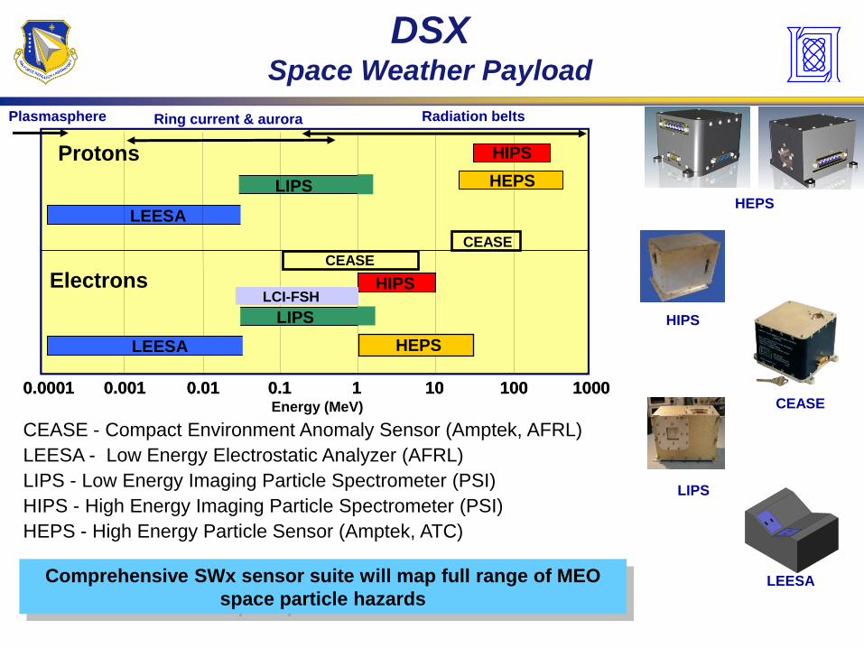
DSX Space Weather Payload
CEASE - Compact Environment Anomaly Sensor (Amptek, AFRL)
LEESA - Low Energy Electrostatic Analyzer (AFRL)
LIPS - Low Energy Imaging Particle Spectrometer (PSI)
HIPS - High Energy Imaging Particle Spectrometer (PSI)
HEPS - High Energy Particle Sensor (Amptek, ATC)
Comprehensive SWx sensor suite will map full range of MEO
space particle hazards
HEPS
CEASE
HIPS
LIPS
LEESA
Radiation beltsRing current & auroraPlasmasphere
Energy (MeV)
HEPS

CREDANCE
SET Carrier (NASA-GSFC)
DSX Space Weather Effects Payload
NASA Space Environment Testbed (SET)
• Correlative Environment Monitor (QinetiQ)
– Dosimeter & deep-dielectric charging package
• DIME (Clemson Univ)
– Dosimetry Intercomparison and Miniaturization
• ELDRS (Arizona State)
– Development of space-based test platform for the
characterization of proton effects and Enhanced Low
Dose Rate Sensitivity (ELDRS) in bipolar junction
transistors
• COTS-2 (CNES and NASA)
– Validation of single event effects mitigation via fault
tolerant methodology
AFRL/PRS “COTS” sensors
Radiometers
Photometers
1”
Objective: directly measure changes in
• Optical transmission,
• Thermal absorption
• Thermal emission
due to MEO radiation environment
SFx experiments will quantify MEO environment effects on advanced
spacecraft technologies & determine basic physics of breakdown

NPM VLF
transmitter
Power flux on the ground (LFCOM) Power flux at 1000 km (LFCOM + Helliwell)
Power flux in the magnetosphere
(LFCOM + Helliwell + PowerTrace)
Science QuestionGround-based VLF Injection
Sequence of
“standard”
models used to
estimate VLF
distribution in
space

≠
Science QuestionWhere is the 20 dB?
Abel & Thorne (1998) Starks, et al. (2008)
Ground transmitter VLF needed in the inner magnetosphere… but where is it?
If not ground transmitters – then what?
Could lightning be more effective then previously thought?

• The four models
operate entirely
differently: empirical,
mode theory, finite
differences, full wave
• All predict essentially
the same ionospheric
penetration fields
• However, all of them overestimate the fields by 20 dB or more.
Questions:
• Where is the transmitter power going?
– Non-linear lower-hyrbid wave – density fluctuation scattering?
• What is scattering the particles at L < 2 ?
–Could lightning be more effective then previously thought?
Science QuestionIt’s not the Absorption Model…

Jul Dec
DSX – RBSP
Magnetic Field Line Footprints
Lightning Flash Rates
1 week
(typical)

DSX
Plasma Environment
Magnetic field
Plasma density
Characteristic frequencies
Radius (Re)
B (
Ga
us
s)
n (
#/c
m^
3)
DSX transmitter

DSX Cold Plasma Regime
S=0
mi/me
R
R
X
L
X
R
R
L
X O
R
L
O
L=0
X
Vacuum
limit

Science QuestionWhat is the Radiation Efficiency?
V = V2-V1
I1 I2
+_
++
+
+ +
+
+ ++
__
__
___
_ _
__
_
Iplasma
• Far-field power radiated ~ 1 2 plasma
dI I I
dt
• Antenna fields heat local plasma
• Anisotropic medium dictates complex power flow
1 2
More complex than in vacuum…

DSX Spiral Modeling Approach
Sheath & plasma heating effects included
Vacuum – dipole radiation in vacuo out to 10 km then cold
plasma propagation
Linear cold plasma – voltage and current distribution
specified on antenna immersed in a cold plasma
Self-consistent linear cold plasma – voltage on terminals
specified, current distribution calculated self-
consistently for antenna immersed in a cold plasma

DSX Global Power Distribution – 3 kHz
Critical Unknown:
Importance of scattering and mode-conversion on power and k-spectrum
3 kHz 6000 km
EQUATORIAL PLANE
L=2
L=3
L=4
L=3
L=4
MERIDIONAL PLANE
Satellite at 6000 km altitude, 0° magnetic lat, vacuum antenna limit; 3 kHz

EQUATORIAL PLANE
L=2
L=3
L=4
L=3
L=4
MERIDIONAL PLANE
Magnetospheric reflection destines rays for lower altitudes at 10 kHz as
compared to 3 kHz
Satellite at 6000 km altitude, 0° magnetic lat, vacuum antenna limit; 10 kHz
DSX Global Power Distribution – 10 kHz

The off-equatorial transmitters lead to very complex field distributions.
L=3
L=4
MERIDIONAL PLANEEQUATORIAL PLANE
L=2
L=3
L=4
Satellite at 6000 km altitude, 30° magnetic lat, vacuum antenna limit; 10 kHz
DSX Global Power Distribution – Off Equator

Same “field line” Same “drift shell & pitch angle”
DSX – RBSP
Magnetic Conjunctions
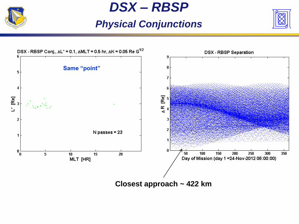
DSX – RBSP
Physical Conjunctions
Closest approach ~ 422 km
Same “point”

Outer BeltInner Belt
Slot
HEO
RBSP
ICO
TSX5
DSX
GEO
LEO
Satellite designers need a definitive model of the trapped energetic particle and plasma environment to include:
Quantitative accuracy
Indications of uncertainty
Flux probability of occurrence and worst cases for different exposure periods
Broad energy ranges
Complete spatial coverage
MEO is sorely under sampled!
L ~ Equatorial Radial Distance (RE)
HEO
GPS
GEO
0
50
100
150
200
250
CR
RE
S M
EP
-SE
U A
no
malies
0
CR
RE
S V
TC
W A
no
malies
Slot
5
10
15
1 2 3 4 5 6 7 80
10
20
30
SC
AT
HA
Su
rface E
SD
SEUs
Internal
Charging
Surface
Charging
(Dose behind 82.5 mils Al)
SCATHA
DSX Why Map the MEO Environment?
UNCLASSIFIED23
En
erg
y (
keV
)
TEM1c PC-1 (45.12%)
keV
2 3 4 5 6 7 8
102
103
104
TEM1c PC-1 (45.12%)
2 3 4 5 6 7 8
102
103
104
TEM1c PC-2 (19.15%)
keV
2 3 4 5 6 7 8
102
103
104
TEM1c PC-2 (19.15%)
2 3 4 5 6 7 8
102
103
104
TEM1c PC-3 (9.36%)
keV
2 3 4 5 6 7 8
102
103
104
TEM1c PC-3 (9.36%)
2 3 4 5 6 7 8
102
103
104
TEM1c PC-4 (6.77%)
keV
L
2 3 4 5 6 7 8
102
103
104
z @ eq
=90o
-1 -0.5 0 0.5 1
TEM1c PC-4 (6.77%)
L
2 3 4 5 6 7 8
102
103
104
log10
Flux (#/cm2/sr/s/keV) @ eq
=90o
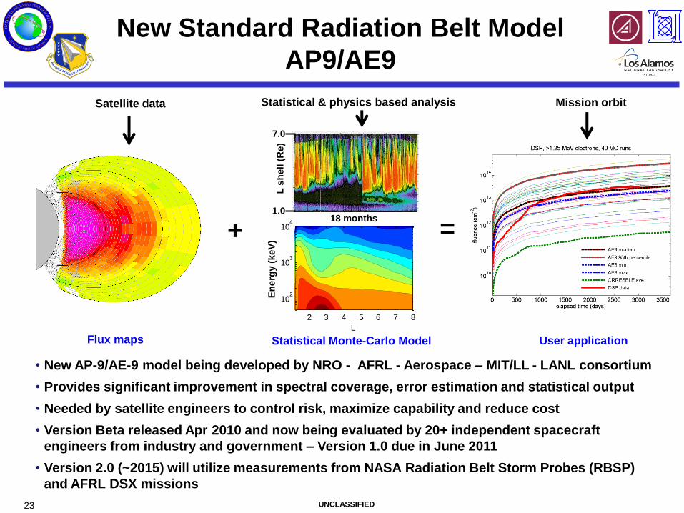
-4 -2 0 2 4 6Flux maps
New Standard Radiation Belt Model
AP9/AE9
18 months
L s
hell (
Re)
1.0
7.0
Statistical Monte-Carlo Model User application
Satellite data Statistical & physics based analysis Mission orbit
+ =
• New AP-9/AE-9 model being developed by NRO - AFRL - Aerospace – MIT/LL - LANL consortium
• Provides significant improvement in spectral coverage, error estimation and statistical output
• Needed by satellite engineers to control risk, maximize capability and reduce cost
• Version Beta released Apr 2010 and now being evaluated by 20+ independent spacecraft
engineers from industry and government – Version 1.0 due in June 2011
• Version 2.0 (~2015) will utilize measurements from NASA Radiation Belt Storm Probes (RBSP)
and AFRL DSX missions

DSX - RBSPSummary
• DSX is manifest for launch as secondary payload on DMSP F-19
with launch in Oct 2012
• DSX will provide high latitude wave & particle coverage in the slot
region to complement RBSP low latitude coverage
– Missing 20 dB of VLF power is a big inner magnetosphere
question
• Tremendous opportunities for bi-static VLF transmit-receive
measurements
– Validate chorus – hiss conversion model
– Determine VLF antenna transmission efficiency
• Lots of good science to be done