the design and analysis of a cache architecture for
TRANSCRIPT

1
AbstractThe effectiveness of texture mapping in enhancing the realism
of computer generated imagery has made support for real-time tex-ture mapping a critical part of graphics pipelines. Despite a recentsurge in interest in three-dimensional graphics from computerarchitects, high-quality high-speed texture mapping has so far beenconfined to costly hardware systems that use brute-force tech-niques to achieve high performance. One obstacle faced by design-ers of texture mapping systems is the requirement of extremelyhigh bandwidth to texture memory. High bandwidth is necessarysince there are typically tens to hundreds of millions of accesses totexture memory per second. In addition, to achieve the high clockrates required in graphics pipelines, low-latency access to texturememory is needed. In this paper, we propose the use of textureimage caches to alleviate the above bottlenecks, and evaluate vari-ous tradeoffs that arise in such designs.
We find that the factors important to cache behavior are (i) therepresentation of texture images in memory, (ii) the rasterizationorder on screen and (iii) the cache organization. Through a detailedinvestigation of these issues, we explore the best way to exploitlocality of reference and determine whether this technique isrobust with respect to different scenes and different amounts oftexture. Overall, we observe that there is a significant amount oftemporal and spatial locality and that the working set sizes are rel-atively small (at most 16KB) across all cases that we studied. Con-sequently, the memory bandwidth requirements of a texture cachesystem are substantially lower (at least three times and as much asfifteen times) than the memory bandwidth requirements of a sys-tem which achieves equivalent performance but does not utilize acache. These results are very encouraging and indicate that cach-ing is a promising approach to designing memory systems for tex-ture mapping.
1 Introduction
Computer graphics is becoming an increasingly important appli-cation. Consequently, there has been much interest from designersof general-purpose microprocessors, media processors, and spe-cialized hardware to provide cost-effective real-time computergraphics capabilities. Examples of recent developments in this areaare the Visual Instruction Set (VIS) in UltraSPARCTM [16] andFBRAM [18] from Sun Microsystems, MMXTM Technology [19]and Accelerated Graphics Port (AGP) [1] from Intel Corporation,Magic Carpet [12] from MIPS Technologies, and Talisman [13]from Microsoft Corporation. In this paper, we focus on one chal-
The Design and Analysis of aCache Architecture for Texture Mapping
Ziyad S. Hakura and Anoop Gupta
Computer Systems LaboratoryStanford UniversityStanford, CA 94305
Copyright © 1997 by the Association for Computing Machinery, Inc. Permission tomake digital or hard copies of part or all of this work for personal or classroom use isgranted without fee provided that copies are not made or distributed for profit orcommercial advantage and that new copies bear this notice and the full citation on thefirst page. Copyrights for components of this work owned by others than ACM mustbe honored. Abstracting with credit is permitted. In Proceedings of 24th ISCA, June2-4, 1997, Denver, Colorado.
lenging aspect of graphics architecture, the design of a memorysystem for texture mapping.
The mapping of images onto the surfaces of three-dimensionalobjects is known as texture mapping. Texture mapping has earnedthe role of a fundamental drawing primitive for its ability to sub-stantially enhance the realism and visual complexity of computer-generated imagery [23, 22]. Examples of this technique include themapping of a 2D color image of a wooden texture to the surface ofa guitar, a road image to a highway, or a grassy plot image to amountain. In addition to the mapping of surface color [5], texturemapping has been used for mapping a myriad of other surfaceparameters including reflection of the environment [21], bumps[9], transparency [7], and shadows [20, 25].
One characteristic of texture mapping is that texture imagesoften require large amounts of memory (typically in the range of afew megabytes to tens of megabytes). The amount of memory isdependent upon the number of textures in a scene and the size ofeach texture. It is generally accepted that the usefulness of texturemapping hardware increases with the amount of memory dedi-cated for textures. Another characteristic of texture mapping is thatit requires many calculations and texture lookups. This characteris-tic causes it to be the main performance bottleneck in graphicspipelines. For each screen pixel (fragment) that is textured, the cal-culations consist of generating texture addresses, filtering multipletexture samples to avoid aliasing artifacts, and modulating the tex-ture color with the pixel color. (Throughout this paper we will usethe terms fragment and screen pixel interchangeably.) Since thenumber of fragments that are textured can be quite large (typicallytens to hundreds of millions per second), and each textured frag-ment requires multiple texture lookups (usually 8), the memorybandwidth requirements to texture memory can be very large (typ-ically several gigabytes per second). In addition, to achieve thehigh clock rates required in graphics pipelines, low-latency accessto texture memory is needed.
The Silicon Graphics’ RealityEngine [14] is an example of ahigh-end parallel graphics architecture that can support real-timetexture mapping. This system uses multiple engines (also calledfragment generators) for texture mapping fragments. Each enginehas an 8-way banked DRAM memory system that is dedicated fortextures (total 16 MB), and can perform eight independent texturelookups in parallel. Since there are multiple fragment generators(between 5 and 20) and each one has its own dedicated memory,the texture images must be replicated in each memory. One prob-lem with this architecture is that an application running on a 20fragment generator system is limited to 16 MB of unique memoryfor textures even though there is a total of 320 MB of texture mem-ory in the system. Therefore, the domain of applications that canutilize the texture mapping hardware is constrained by the limitedamount of unique memory.
An alternative approach for providing fast texture accesses andhigh bandwidths is to use an SRAM cache with each fragmentgenerator instead of a dedicated DRAM memory. The premise ofthis idea is that there is a substantial amount of locality of refer-
2
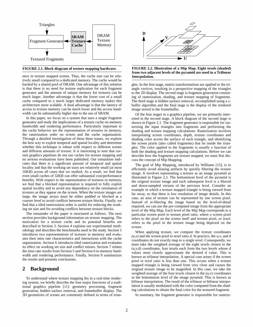
ence in texture mapped scenes. Thus, the cache size can be rela-tively small compared to a dedicated memory. The cache would bebacked by a shared pool of DRAM. One advantage of this solutionis that there is no need for texture replication for each fragmentgenerator and the amount of unique memory for textures can bemuch larger. Another advantage is that the lower cost of a smallcache compared to a much larger dedicated memory makes thisarchitecture more scalable. A final advantage is that the latency ofaccess to texture memory can be much lower and the access band-width can be substantially higher due to the use of SRAM.
In this paper, we focus on a system that uses a single fragmentgenerator and study the implications of a texture cache on memorybandwidth and rendering performance. Particularly important tothe cache behavior are the representation of textures in memory,the rasterization order on screen and the cache organization.Through a detailed investigation of these three issues, we explorethe best way to exploit temporal and spatial locality and determinewhether this technique is robust with respect to different scenesand different amounts of texture. It is interesting to note that cur-rent graphics pipelines do not use caches for texture mapping andno serious evaluations have been published. Our simulation indi-cates that there is a significant amount of temporal and spatiallocality and that the working set sizes are relatively small (at most16KB) across all cases that we studied. As a result, we find thateven small caches of 32KB can offer substantial cost/performancebenefits. With respect to the representation of textures in memory,we find that a blocked representation is required to fully exploitspatial locality and to avoid any dependency on the orientation oftextures as they appear on the screen. When the texture images arelarge, the image arrays must be either padded or blocked at acoarser level to avoid conflicts between texture blocks. Finally, wefind that a tiled rasterization order is useful for reducing the work-ing set size and for avoiding conflicts between texture blocks.
The remainder of the paper is structured as follows. The nextsection provides background information on texture mapping. Themotivation for a texture cache and its potential benefits aredescribed in Section 3. Section 4 explains our experimental meth-odology and describes the benchmarks used in the study. Section 5introduces two representations of textures in memory and evalu-ates their miss rate characteristics and interactions with the cacheorganization. Section 6 introduces tiled rasterization and evaluatesits effect on working set size and conflict misses. Section 7 relatesthe miss rate results from Section 5 and Section 6 to memory band-width and rendering performance. Finally, Section 8 summarizesthe results and presents conclusions.
2 Background
To understand where texture mapping fits in a real-time render-ing system, we briefly describe the four major functions of a tradi-tional graphics pipeline [11]: geometry processing, fragmentgeneration, hidden surface removal, and framebuffer display. The3D geometries of scenes are commonly defined in terms of trian-
FIGURE 2.1. Block diagram of texture mapping hardware.
Fragment GeneratorSRAMTextureCache
DRAMTextureMemory
Triangles
Textured Fragments
gles. In the first stage, matrix transformations are applied to the tri-angle vertices, resulting in a perspective mapping of the trianglesto the 2D display. The second stage is fragment generation consist-ing of rasterization, shading, and texture mapping of fragments.The third stage is hidden surface removal, accomplished using a z-buffer algorithm and the final stage is the display of the renderedimage stored in the framebuffer.
Of the four stages in a graphics pipeline, we are primarily inter-ested in the second stage. A block diagram of the second stage isshown in Figure 2.1. The fragment generator is responsible for ras-terizing the input triangles into fragments and performing theshading and texture mapping calculations. Rasterization involvesinterpolating screen coordinates, depth, texture coordinates andshading color across the surface of each triangle, and identifyingthe screen pixels (also called fragments) that lie inside the trian-gles. The color applied to the fragments is usually a function ofboth the shading and texture mapping calculations. Before we candescribe how the fragments are texture mapped, we must first dis-cuss the concept of Mip Mapping.
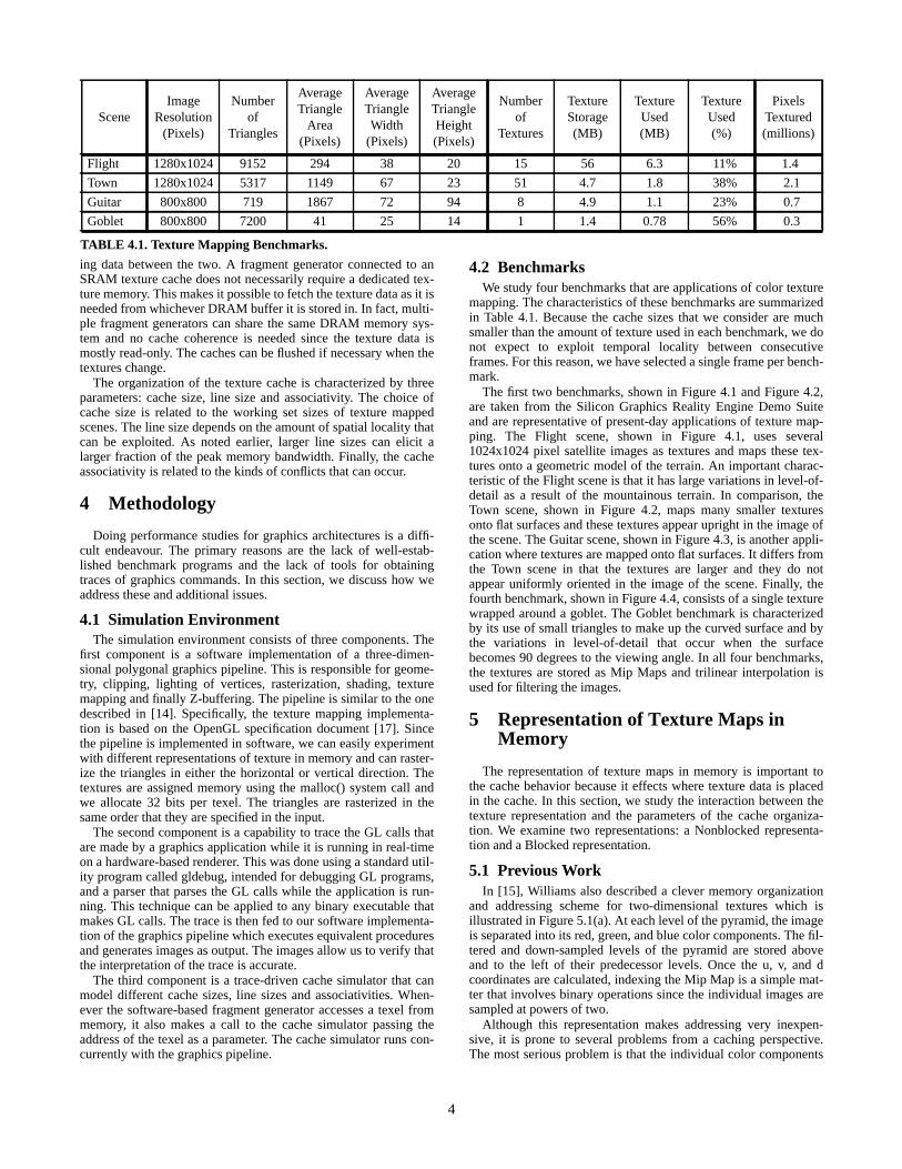
The goal of Mip Mapping, introduced by Williams [15], is toefficiently avoid aliasing artifacts by quickly filtering the textureimage. It involves representing a texture as an image pyramid asillustrated in Figure 2.2. The bottommost level of the pyramid isthe original texture image and each subsequent level is a filteredand down-sampled version of the previous level. Consider anexample in which a texture mapped triangle is being viewed fromfar away, so that there is low resolution of image details. In thiscase, an area of texture can be represented by one screen pixel.Instead of re-filtering the image based on the level-of-detailrequired, we can use the pre-computed image from the appropriatelevel of the Mip Map. Each level of the Mip Map corresponds to aparticular screen pixel to texture pixel ratio, where a screen pixelrefers to the pixel on the screen itself and texture pixel, or texel,refers to the pixel in the texture image being depicted on thescreen.
When applying texture, we compute the texture coordinates(u,v) and the screen pixel to texel ratio d. In practice, the u,v, and dcoordinates do not exactly map to a single texel. Consequently, wemust take the weighted average of the eight texels closest to the(u,v,d) coordinates, four texels each from the two levels whose dvalues most closely approximate the desired d value. This isknown as trilinear interpolation. A special case arises if the screenpixel to texel ratio is less than one. This occurs when a texturemapped triangle is being viewed from very close and causes theoriginal texture image to be magnified. In this case, we take theweighted average of the four texels closest to the (u,v) coordinatesin the bottommost level of the image pyramid. This is known asbilinear interpolation. The result of the trilinear or bilinear interpo-lation is usually modulated with the color computed from the shad-ing calculations to obtain the final color for the textured fragment.
In summary, the fragment generator is responsible for rasteriz-
FIGURE 2.2. Illustration of a Mip Map. Eight texels (shaded)from two adjacent levels of the pyramid are used in a TrilinearInterpolation.
U
VD

3
ing triangles into fragments, computing level-of-detail and MipMap texture addresses for each fragment, filtering the texels thatare accessed using either trilinear or bilinear interpolation, andfinally applying the texture color to the fragments. Typical unopti-mized computational costs for each of the operations of a fragmentgenerator are shown in Table 2.1. Since these costs are quite high,fragment generators often exploit deep pipelining and parallel-ism. In fact, most of the costs are incurred by texture mapping.
3 Texture Cache: Motivation and Benefits
In this section, we identify the types of locality of reference thatare present in texture accesses and discuss the benefits of addingan SRAM texture cache between the fragment generator andDRAM texture memory.
3.1 Locality of Reference in Texture MappingThe effectiveness of a memory hierarchy depends on locality of
reference in data accesses. Both spatial and temporal locality arepresent in texture mapping.
3.1.1 Spatial Locality
The representation of textures as Mip Maps contributes to spa-tial locality in texture accesses. The Mip Map accesses have a highdegree of spatial locality since the level of the map is selected toclosely match the level-of-detail that is being drawn on the screen.In essence, this means that movements of one pixel in screen spaceroughly correspond to movements of one texel in texture space,hence the spatial locality in texture space. The spatial locality inMip Map accesses is thus present irrespective of the scene.
3.1.2 Temporal Locality
Temporal locality in accesses to texture data is present whenrendering a single frame and between consecutive frames. We gen-erally do not expect our caches to exploit temporal localitybetween consecutive frames because the cache sizes that we con-sider are much smaller than the amount of texture data that is typi-
Phase ofFragment Generator
ComputationPrecision
Add
/Sub
trac
t/Sh
ift
Mul
tiply
Div
ide
Num
ber
of T
extu
r eM
emor
y A
cces
ses
Per Triangle Setup Fixed/Floating 89 64 1 -
Per Fragment Raster-ization and Shading
Fixed/Floating 11 1 -
Level-of-detail, d Fixed/Floating 9 9 -
Texel coordinatesnearest (u,v,d)
FixedInteger
514
5 -
Texel addresscalculation
Integer Dependent uponMemory
Representation.See Section 5.
-
Trilinear Interpolation/Bilinear Interpolation
Fixed 5624
2812
84
Modulation withfragment color
Fixed 8 4 -
TABLE 2.1. Computational costs of the operations of afragment generator. Apart from triangle setup, all the costsare on a per fragment basis.
cally used by a single frame. Between memory and disk, however,this kind of temporal locality is of interest. Within a single frame,two types of temporal locality are present: locality arising fromoverlap of accesses needed for filtering between neighboring frag-ments and locality arising from repeated texture. Below, we dis-cuss each of these two types of temporal locality in more detail.
Overlap of Accesses between Neighboring FragmentsTemporal locality is present between the texel accesses of neigh-
boring fragments. Since each textured fragment must access multi-ple texels for trilinear or bilinear interpolation, it is expected thatsome of these accesses will overlap with the texel accesses ofneighboring fragments. We measured the average number ofaccesses per texel made by a spatially contiguous group of frag-ments across all four benchmark scenes, which are described inSection 4. The results for trilinear interpolation (lower level), tri-linear interpolation (upper level) and bilinear interpolation are 4,14 and 18, respectively. For trilinear interpolation, we distinguishbetween texel accesses that are to the more detailed level, lowerlevel, and the less detailed level, upper level, of the two adjacentlevels of the Mip Map that are used in the interpolation. Theseresults clearly show that the texels in the upper level of a trilinearinterpolation are accessed a larger number of times than the texelsin the lower level. Since the lower level is more detailed than theupper level, it is traversed more rapidly and this leads to feweraccesses per texel. In general, we expect texels in the lower levelof a trilinear interpolation to be accessed an average of four timesand the texels in the upper level to be accessed an average of six-teen times. For bilinear interpolation, the number of accesses pertexel is directly related to the amount of texture magnification andthis can vary widely depending on the scene.
Repeated TextureTemporal locality is also present when a texture is repeated
across the surface of an object. An example application is a wallthat is textured by repeating a 2D texture image of an individualbrick. Since the amount of repetition is a function of the texturecoordinates defined in the high-level geometric description of thescene, this type of temporal locality is very scene dependent. Wemeasured the average number of times a texel is repeated in thebenchmark scenes. The results for the Town, Guitar, Goblet andFlight scenes are 2.9, 1.7, 1.1 and 1.0 times, respectively.
3.2 Texture Cache BenefitsThe evolution of DRAM technology motivates the use of an
SRAM texture cache. The rapid growth in DRAM density hasmeant that fewer DRAM chips are needed to construct a memoryof a fixed size. The use of higher density memory chips has led to adecline in bandwidth per Megabyte of memory [24]. An SRAMtexture cache can exploit locality of reference to hide most of thetexture accesses from reaching memory, thus lowering the band-width requirements.
Another reason for adding an SRAM cache is that block trans-fers of cache lines between the cache and memory make it possibleto get the most bandwidth out of the memory. Present-day DRAMarchitectures are optimized for long burst transfers to microproces-sor caches since this amortizes the setup costs of the transfer overmany bytes and leads to the most efficient memory bus utilization.
A third reason for having an SRAM texture cache is that staticmemories typically have shorter access latencies than dynamicmemories. The SRAM cache can be tightly coupled with the frag-ment generator which makes it possible to run the fragment gener-ator at higher clock rates. This is an incentive for integrating theSRAM cache onto the same chip as the fragment generator.
Finally, a recent trend in computer graphics has been the use ofrendered images as textures [3]. As a result, it has become desir-able to unify the framebuffer and texture memories to avoid copy-
4
ing data between the two. A fragment generator connected to anSRAM texture cache does not necessarily require a dedicated tex-ture memory. This makes it possible to fetch the texture data as it isneeded from whichever DRAM buffer it is stored in. In fact, multi-ple fragment generators can share the same DRAM memory sys-tem and no cache coherence is needed since the texture data ismostly read-only. The caches can be flushed if necessary when thetextures change.
The organization of the texture cache is characterized by threeparameters: cache size, line size and associativity. The choice ofcache size is related to the working set sizes of texture mappedscenes. The line size depends on the amount of spatial locality thatcan be exploited. As noted earlier, larger line sizes can elicit alarger fraction of the peak memory bandwidth. Finally, the cacheassociativity is related to the kinds of conflicts that can occur.
4 Methodology
Doing performance studies for graphics architectures is a diffi-cult endeavour. The primary reasons are the lack of well-estab-lished benchmark programs and the lack of tools for obtainingtraces of graphics commands. In this section, we discuss how weaddress these and additional issues.
4.1 Simulation EnvironmentThe simulation environment consists of three components. The
first component is a software implementation of a three-dimen-sional polygonal graphics pipeline. This is responsible for geome-try, clipping, lighting of vertices, rasterization, shading, texturemapping and finally Z-buffering. The pipeline is similar to the onedescribed in [14]. Specifically, the texture mapping implementa-tion is based on the OpenGL specification document [17]. Sincethe pipeline is implemented in software, we can easily experimentwith different representations of texture in memory and can raster-ize the triangles in either the horizontal or vertical direction. Thetextures are assigned memory using the malloc() system call andwe allocate 32 bits per texel. The triangles are rasterized in thesame order that they are specified in the input.
The second component is a capability to trace the GL calls thatare made by a graphics application while it is running in real-timeon a hardware-based renderer. This was done using a standard util-ity program called gldebug, intended for debugging GL programs,and a parser that parses the GL calls while the application is run-ning. This technique can be applied to any binary executable thatmakes GL calls. The trace is then fed to our software implementa-tion of the graphics pipeline which executes equivalent proceduresand generates images as output. The images allow us to verify thatthe interpretation of the trace is accurate.
The third component is a trace-driven cache simulator that canmodel different cache sizes, line sizes and associativities. When-ever the software-based fragment generator accesses a texel frommemory, it also makes a call to the cache simulator passing theaddress of the texel as a parameter. The cache simulator runs con-currently with the graphics pipeline.
SceneImage
Resolution(Pixels)
Numberof
Triangles
AverageTriangle
Area(Pixels)
AverageTriangleWidth
(Pixels)
AverageTriangleHeight(Pixels)
Numberof
Textures
TextureStorage(MB)
TextureUsed(MB)
TextureUsed(%)
PixelsTextured(millions)
Flight 1280x1024 9152 294 38 20 15 56 6.3 11% 1.4
Town 1280x1024 5317 1149 67 23 51 4.7 1.8 38% 2.1
Guitar 800x800 719 1867 72 94 8 4.9 1.1 23% 0.7
Goblet 800x800 7200 41 25 14 1 1.4 0.78 56% 0.3
TABLE 4.1. Texture Mapping Benchmarks.
4.2 BenchmarksWe study four benchmarks that are applications of color texture
mapping. The characteristics of these benchmarks are summarizedin Table 4.1. Because the cache sizes that we consider are muchsmaller than the amount of texture used in each benchmark, we donot expect to exploit temporal locality between consecutiveframes. For this reason, we have selected a single frame per bench-mark.
The first two benchmarks, shown in Figure 4.1 and Figure 4.2,are taken from the Silicon Graphics Reality Engine Demo Suiteand are representative of present-day applications of texture map-ping. The Flight scene, shown in Figure 4.1, uses several1024x1024 pixel satellite images as textures and maps these tex-tures onto a geometric model of the terrain. An important charac-teristic of the Flight scene is that it has large variations in level-of-detail as a result of the mountainous terrain. In comparison, theTown scene, shown in Figure 4.2, maps many smaller texturesonto flat surfaces and these textures appear upright in the image ofthe scene. The Guitar scene, shown in Figure 4.3, is another appli-cation where textures are mapped onto flat surfaces. It differs fromthe Town scene in that the textures are larger and they do notappear uniformly oriented in the image of the scene. Finally, thefourth benchmark, shown in Figure 4.4, consists of a single texturewrapped around a goblet. The Goblet benchmark is characterizedby its use of small triangles to make up the curved surface and bythe variations in level-of-detail that occur when the surfacebecomes 90 degrees to the viewing angle. In all four benchmarks,the textures are stored as Mip Maps and trilinear interpolation isused for filtering the images.
5 Representation of Texture Maps inMemory
The representation of texture maps in memory is important tothe cache behavior because it effects where texture data is placedin the cache. In this section, we study the interaction between thetexture representation and the parameters of the cache organiza-tion. We examine two representations: a Nonblocked representa-tion and a Blocked representation.
5.1 Previous WorkIn [15], Williams also described a clever memory organization
and addressing scheme for two-dimensional textures which isillustrated in Figure 5.1(a). At each level of the pyramid, the imageis separated into its red, green, and blue color components. The fil-tered and down-sampled levels of the pyramid are stored aboveand to the left of their predecessor levels. Once the u, v, and dcoordinates are calculated, indexing the Mip Map is a simple mat-ter that involves binary operations since the individual images aresampled at powers of two.
Although this representation makes addressing very inexpen-sive, it is prone to several problems from a caching perspective.The most serious problem is that the individual color components

5
of a texel are always separated by powers of two bytes in memorysince the texture image dimensions are powers of two. (Note thatin most graphics libraries including OpenGL, the texture imagedimensions are either restricted to be powers of two or the imagesare padded so that the dimensions are powers of two.) Thus, it isvery likely that the individual color components will map to thesame line in the cache resulting in conflicts. Another problem isthat the representation does not exploit spatial locality that wouldbe present if the color components were stored contiguously in thesame cache line. Finally, since the image is separated by compo-nent, reading a texel from the cache requires three separateaccesses with tag comparisons for each access.
5.2 Base Nonblocked RepresentationAn alternative representation is illustrated in Figure 5.1(b). In
this representation, the red, green, blue and alpha components arestored contiguously. Each level of the pyramid is represented by itsown two-dimensional array and each array is stored in row-majororder. We will consider this representation as the base representa-tion for the remainder of this paper since it is not prone to the prob-lems mentioned previously.
5.2.1 Texel Addressing
The main advantage of the base representation is that it requiresthe fewest number of addressing calculations. The addressing cal-culations, shown below, assume that the dimensions of the texturearrays are powers of two. The texel addressing calculations mustbe performed eight times per fragment since a trilinear interpola-tion requires eight texture samples.
All variables are a function of the Mip Map level.tu, tv: texel u- and v-coordinatesbase: starting address of 2D texture arraylw: log2(width of 2D texture array in pixels)
Texel address = base + (tv << lw) + tu
5.2.2 Cold Misses
Cold misses cannot be avoided and so they represent the lowerbound for miss rates in the cache. Figure 5.2 shows graphs of missrate versus cache size measured for fully associative caches withan LRU replacement policy. These graphs assume a line size of 32bytes and fully associative caches so that we can ignore conflictmisses. We study the effect of line size on cold misses and deferthe discussion of conflict misses to Section 5.3.3.
Cold misses typically occur in two places: along triangle edgeswhere the textures are first accessed, and in the interior of large tri-angles when the texture accesses cross cache line boundaries. Thecold miss rates can be deduced from the miss rates for the largecaches since they do not include capacity misses. (Note that thecold miss rates are the same regardless of whether rasterization ishorizontal or vertical; we discuss the effect of rasterization direc-
R G B A
Level 0 1 2 3 4
R
GB
R
GB
RGB
(a) (b)
FIGURE 5.1. (a) Mip Map representation proposed by Will-iams. (b) Base nonblocked representation.
tion on working set size in Section 5.2.3). The cold miss rates forthe Town, Guitar, Goblet and Flight scenes are 0.55%, 0.87%,1.5%, and 2.8% respectively. These miss rates are quite low con-sidering that the line size of 32 bytes holds just eight texels.
One factor that contributes to differences in cold miss rate is theamount of temporal locality in the form of repeated texture. Aspreviously noted in Section 3.1.2, the amount of repetition of tex-tures is very scene dependent. Another factor is the frequency ofchanges in level-of-detail across the surfaces that are textured. Inthe Town and Guitar scenes, the surfaces are predominantly flatcausing the variations in level-of-detail to be gradual. As a result,we find that a large fraction of each line of texture data that isfetched into the cache is used. In comparison, the mountainous ter-rain in the Flight scene causes frequent changes in level-of-detail.Consequently, the accesses are fragmented across different levelsof the Mip Map and a smaller fraction of each line of texture datathat is fetched into the cache is used. Since more lines are neededfor texturing, the cold miss rates are higher.
We also measured the cold miss rates for caches with a larger128 byte line size. The results for the Town, Guitar, Goblet andFlight scenes are 0.15%, 0.25%, 0.42%, and 1.1% respectively. Wesee that the cold miss rates are much reduced with increasing linesize, indicating the presence of substantial spatial locality.
5.2.3 Working Set Size
The working set size is a measure of the amount of data that isactively in use at a particular time. Most applications have a hierar-chy of working sets [6]. In a graph of miss rate versus cache size,the different levels of the working set hierarchy can be seen as pla-teaus followed by sharp reductions in miss rate at particular cachesizes.
One can consider the coarsest level of the working set hierarchyin texture mapping to consist of all the texture data required to ren-der an image. The Principle of Texture Thrift [4] defines the mini-mum amount of data required to render an image:
Given a scene consisting of textured 3D surfaces, the amount oftexture information minimally required to render an image of thescene is proportional to the resolution of the image and is indepen-dent of the number of surfaces and the size of the textures.
This principle is a consequence of the fact that each pixel of theimage can represent at most one filtered sample of texture. Theadvantage of representing textures in the form of Mip Maps is thatthe amount of data used in filtering for each pixel is fixed regard-less of the level-of-detail.
We are interested in understanding the makeup of the first sig-nificant working set because it corresponds to the smallest cachesize that one would consider using for caching texture images. Weare also interested in making a worst-case estimate of the size ofthe first significant working set to generalize our analysis beyondthe benchmarks that we study. We define the first significant work-ing set as the first level of the working set hierarchy and begin bynoting that a triangle is rasterized one scan line at a time, where ascan line consists of either a horizontal or vertical span of pixels inscreen space. We assume for our worst-case analysis that the trian-gle being rasterized is large and spans the entire area of the screen.We have shown that there is spatial and temporal locality in theaccesses to texture data, especially by accesses from adjacent scanlines. A cache that is large enough to hold the texture data neededfor an entire scan line can exploit such localities of reference tosignificantly reduce miss rates. Thus, we see that the first levelworking set consists of the texture data needed for an entire scanline, and a significant reduction in miss rate occurs when the cacheis large enough to hold this working set. Two parameters that canplace a bound on the worst-case working set size are the textureimage size and the screen size. If the texture image size is less than

6
the screen size, the texture is wrapped around and repeated. In thiscase, the worst case working set size is bounded by the cache linesize multiplied by the length of the diagonal of the texture image,since this is the maximum length through the texture and the tex-ture can appear in an arbitrary orientation on the screen. On theother hand, if the texture image size is greater than the screen size,the worst case working set size is bounded by the cache line sizemultiplied by the maximum width or height of the screen, depend-ing upon whether we rasterize horizontally or vertically1.
We have measured the average runlength of texel accesses fromthe same texture. The results for the Town, Guitar and Flightscenes, which are applications of more than one texture, are223,629, 553,745 and 562,154, respectively. An underlyingassumption is that the triangles are processed in the same orderthat they are specified in the high-level geometric description ofthe scene. These long runlengths demonstrate that the working setis limited to one texture at any point in time.
When rendering a span of pixels in screen space, texels (texturepixels) may be traversed in arbitrary orientations on the screen. Inthe worst case, the texture accesses can be streaming verticallythrough the texture causing only a fraction of each cache line thatis brought into the cache to be actively used. The net effect is thatthe working set size is larger than it needs to be. This is a short-coming of the base representation that we have chosen.
Figure 5.2(a) shows the miss rate results versus cache size whenthe scenes are rasterized horizontally. The first level working setsizes for the Flight, Town, Guitar and Goblet scenes are 4KB,8KB, 16KB, and 16KB respectively. These working set sizes are avery small fraction of the total amount of texture that is used torender each scene (please see Table 4.1 for the full texture contentused) and indicate that texture caching can be effective with rela-tively small cache sizes.
Figure 5.2(b) shows the miss rates versus cache size when thescenes are rasterized vertically. Compared to Figure 5.2(a), themiss rates for the Town scene have substantially increased forsmall cache sizes, whereas the miss rates for the other scenes havenot changed quite as much. The first level working set size for theTown scene has grown from 8KB to 16KB because of a mismatchbetween the base representation and the rasterization direction. Infact, since most of the textures appear upright in the image of theTown scene, vertical rasterization causes the direction in which thetexels are accessed to be perpendicular to the direction in which
1. The screen rasterization path that would lead to the smallest working setwould follow a Peano-Hilbert order since this would traverse a region ofthe texture in a spatially contiguous manner.
� � flight-horizontal� � guitar-horizontal� � goblet-horizontal� � town-horizontal
|1
|2
|4
|8
|16
|32
|64
|128
|256
|0
|2
|4
|6
|8
|10
|12
|14
|16
Cache Size (KB)
Mis
s R
ate
(%)
�
�
�� � � � � �
�
�
�
�
�
�� � �
� � ��
� � � � �
��
�� � � � � �
� � flight-vertical� � guitar-vertical� � goblet-vertical� � town-vertical
|1
|2
|4
|8
|16
|32
|64
|128
|256
|0
|2
|4
|6
|8
|10
|12
|14
|16
Cache Size (KB)
Mis
s R
ate
(%)
�
�
�
� � � � � �
�
�
�
�
�
�� � �
� � ��
� � � � �
�
�
�
�
�� � � �
(a) (b)
FIGURE 5.2. Results for the base representation using fully associative caches. The line size is 32 bytes (8 texels).(a) Horizontal rasterization (row major order). (b) Vertical rasterization (column major order).
the texels are stored leading to worst-case behavior. In the Flightscene, the effect is less pronounced because the triangles are mod-erately sized. The Goblet scene results do not change because thetriangles are relatively small. The results for the Guitar scene donot change very much because the textures in this scene are notuniformly oriented in any particular direction. From an architec-tural perspective, the important point is that the base representationis sensitive to the direction of texture accesses. For the remainderof this paper, we report results using vertical rasterization for theTown scene since this leads to worst-case behavior, and reportresults using horizontal rasterization for the Flight, Guitar andGoblet scenes.
In summary, we have shown that the cold miss rates are verylow and can be further reduced with larger line sizes. The long tex-ture runlengths, measured with the same rendering sequence asthat taken by actual hardware engines that do texture mapping,indicate that the working set is limited to one texture. In addition,the working set sizes are very small compared with the amount oftexture that is used to render each scene, justifying the use of rela-tively small texture caches. Finally, we found that the base repre-sentation is sensitive to the orientation of textures on the screen.
5.3 Blocked RepresentationA blocked representation can be used to reduce the dependency
on the orientation of textures, as seen by the viewer, and to exploitmore spatial locality. A blocked representation of a 5-level MipMap is illustrated in Figure 5.3. In this representation, also com-monly known as Tiled, texels that are within a square region(block) of a two-dimensional image are ordered consecutively inmemory. The idea of texture blocking is previously discussed in[4] and [10]. There are several issues that are raised by this repre-sentation. First, what is the addressing overhead associated withblocking? Second, how do we select the block size and is it relatedto the cache line size? Third, what are the improvements in missrate as we increase the cache line size? Finally, what is the effect ofblocking on conflict misses? In the following subsections, we dis-cuss each of these issues in turn.
5.3.1 Texel Addressing Overhead
The blocked representation converts two-dimensional texturearrays into four-dimensional arrays. Therefore, the texel address-ing calculations must be done in a two-step process which is illus-trated below. We assume that the blocks are square and havedimensions that are powers of two. Furthermore, we assume thatthe blocks have the same dimensions across all Mip Map levels.

7
bw, bh: block width and height in texels. These are equal andare powers of two.
lbw, lbh: log2(bw or bh)bs: log2(bw * bh)
The following variables are a function of the Mip Map level.rs: log2(width of texture array in texels * bh)tu, tv: texel u- and v-coordinatesbx, by: block coordinatessx, sy: sub-block coordinates in texelsbase: starting address of 4D texture array
bx = tu >> lbwby = tv >> lbhBlock address = base + (by << rs) + (bx << bs)
sx = tu & (bw - 1)sy = tv & (bh - 1)Texel address = Block address + (sy << lbw) + sx
The variables bx, by, sx, and sy are simply bit-fields of the u- andv- texel coordinates, tu and tv. Furthermore, two of the shift opera-tions shown above, involving the variables bs and lbw, have con-stant shift amounts assuming that the block dimensions remainfixed. Hence, the aggregate hardware overhead of the blocked rep-resentation compared to the base representation simply consists oftwo additions. These operations are incurred in the calculation ofthe block address.
5.3.2 Selecting a Block Size and Cache Line Size
The next question we would like to answer is whether there isany interaction between the block size used in the representationand cache line size. Figure 5.4 shows miss rate versus cache linesize for a variety of block sizes. We chose a 32KB cache for ourmeasurements because this cache size is larger than the workingset sizes which we noted earlier. The graph in Figure 5.4(a) is forthe Town scene. It shows that the lowest miss rates occur when theblock size most closely matches the cache line size. For example,the lowest miss rate for a 64 byte cache line is for a 4x4 blockwhich has a block size of 64 bytes. This effect can be explained byobserving that individual cache lines that hold square regions oftexture are most effective at exploiting spatial locality. When theblock sizes greatly differ from the cache line sizes, we find that theworking set sizes can become unnecessarily large leading to manycapacity misses. The results for the Guitar scene, shown in Figure5.4(b), are very similar.
We would like to quantify the extent of reduction in miss rate asthe line size is increased. Figure 5.5 shows the effects of line andblock size on miss rate for a fully associative 32KB cache. At32KB, the primary misses that remain are cold misses and thesemisses are independent of the orientation of textures as viewed onthe screen. The miss rates for the Flight, Goblet, Guitar and Townscenes at a line size of 32 bytes are 2.8%, 1.5%, 1.2% and 0.8%respectively. The miss rates at a line size of 128 bytes are 0.87%,
Texture Data Blocks
Level 0 1 2 3 4
FIGURE 5.3. An illustration of the blocked representation fora texture Mip Map.
0.41%, 0.36% and 0.21%. There appears to be a significant reduc-tion in miss rate as the line and block sizes are increased.
Thus far, we have presented results for a 32KB cache and wehave found that this cache size is adequate for holding the workingsets of all four scenes. In Figure 5.6, we show results specific to theGuitar scene for different cache sizes. These graphs demonstratethat the blocked representation when coupled with larger line andblock sizes, leads to a reduction in the number of capacity missesfor cache sizes that are smaller than the working set size. In Figure5.4 we saw that increasing the line size alone, without blocking,leads to worse miss rates. We can conclude that the blocked repre-sentation is an essential component for reducing the frequency ofcapacity misses. We have found that the other benchmark scenesexperience similar reductions in capacity misses (although notshown here due to space reasons) when the cache sizes are smallerthan the working set sizes.
In summary, we can conclude that the best block size to use fortexturing corresponds to when the memory required to store oneblock of texture is the same as the cache line size. Furthermore, forscenes that we evaluate, there is enough spatial locality that largerline sizes can be used.
5.3.3 Conflict Misses
Thus far, we have ignored conflict misses and have only shownresults for fully associative caches. In this section, we identify the
� � nonblocked� � 2x2� � 4x4� � 8x8� � 16x16
|16
|32
|64
|128
|256
|0.0
|0.4
|0.8
|1.2
|1.6
|2.0
|2.4
|2.8
|3.2
Line Size (Bytes)
Mis
s R
ate
(%)
�
�
�
�
�
�
�
�
�
�
�
�
�
�
�
�
�
�
�
�
�
�
�
(b)
� � nonblocked� � 2x2� � 4x4� � 8x8� � 16x16
|16
|32
|64
|128
|256
|0.0
|0.4
|0.8
|1.2
|1.6
|2.0
|2.4
|2.8
|3.2
Line Size (Bytes)
Mis
s R
ate
(%)
�
� �
�
�
�
� �
�
�
�
�
� �
�
�
�
��
�
�
�
�
�
(a)
FIGURE 5.4. The interaction between block size and cache linesize. These results were measured using fully associative 32KBcaches. The block dimensions are given in texels.(a) Town-vertical. (b) Guitar-horizontal.

8
kinds of conflict misses that can occur and discuss how they can beavoided.
In Figure 5.1(b), we showed that in the base nonblocked repre-sentation, the levels of a Mip Map are stored separately in memoryas two-dimensional arrays. Since these arrays are usually restrictedto have dimensions that are powers of two, conflicts are prone tooccur between neighboring texels that are in the same column.This kind of conflict miss can be avoided with the use of a blockedrepresentation. The texels that lie within a block are guaranteed notto conflict in the cache since they are stored consecutively in mem-ory. Moreover, since the block size is selected to be the same as thecache line size, the group of texels that lie within a block would beheld by the same cache line.
Conflicts can also occur between blocks which are in differentlevels of a Mip Map. These conflicts are likely to be avoided with atwo-way set-associative cache since trilinear interpolations simul-taneously access at most two levels of a Mip Map.
Figure 5.7 shows graphs of miss rate versus cache size for dif-ferent cache associativities. A relatively large line size of 128bytes was selected for these experiments because conflict missesare more likely to occur when there are fewer lines in the cache.Thus, these results are indicative of the worst-case effect of con-flicts on miss rate. The results in Figure 5.7(a) are for the Gobletscene and show that there is a significant difference in miss ratesbetween the direct-mapped caches and the two-way set-associativecaches. Since the triangles in the Goblet scene have fairly smallareas, it is unlikely that conflicts will occur between blocks that arein the same level of a Mip Map. Hence, we attribute this differencein miss rates to conflicts between blocks that are in different levelsof a Mip Map. The graph also shows that the two-way set-associa-tive caches have the same miss rates as the fully associative cachesindicating that increasing the associativity beyond two-way doesnot lead to any further improvement in miss rates.
The results in Figure 5.7(a) for the Goblet scene assumed ablocked representation. Had the representation been nonblocked,an eight-way associative cache would have been required toachieve the same miss rates as a fully associative cache among thesmall cache sizes. This result demonstrates that the blocked repre-sentation is useful for avoiding conflicts between neighboring tex-els in different rows of a 2D array.
The results in Figure 5.7(b) are for the Town scene. In thisgraph, we also find that two-way set-associativity is useful foreliminating conflicts between adjacent levels of a Mip Map. How-
� � flight-horizontal� � goblet-horizontal� � guitar-horizontal� � town-vertical
|16
|32
|64
|128
|256
|0.0
|0.7
|1.4
|2.1
|2.8
|3.5
|4.2
|4.9
|5.6
Mis
s R
ate
(%)
2x2 4x4 4x4 8x8 8x8Line and Block Size
�
�
�
�
�
�
�
�
� �
�
�
�
��
�
�
��
�
FIGURE 5.5. Effect of changes in line and block size on missrates for all four scenes. These results were measured using ful-ly associative 32KB caches. The block dimensions are given intexels.
ever, unlike Figure 5.7(a), there is a notable difference between themiss rates for the two-way set-associative caches and the fullyassociative caches. Vertical rasterization through the upright tex-tures in the Town scene leads to conflicts between multiple blockswhich lie within the same 2D array. The graph for the Town scenealso shows that limited cache associativities beyond two-way arebeneficial for small cache sizes, but are ineffective at avoiding thiskind of block conflict miss among large caches. The results for theGuitar scene are similar since the textures are accessed along avariety of paths and the triangles are large. The results for theFlight scene are also similar except that most of the conflicts areavoided when the caches are eight-way set-associative and this isattributed to the fact that the triangles are moderately sized.
In summary, the blocked representation prevents conflicts fromoccurring between neighboring texels. Conflicts are also prone tooccur between blocks. Conflicts between blocks at adjacent levelsof the Mip Map can be successfully eliminated with two-way set-associative caches. Conflict misses that occur within the same 2Darray are harder to prevent because the textures can be accessedalong any path. In the next section, we discuss a tiled rasterizationorder that has the effect of reducing the number of blocks in theworking set that can conflict with each other.
6 Rasterization Order and Tiling inScreen Space
The order in which screen pixels are traversed to determinewhether they lie within the boundary of a triangle is the rasteriza-tion order. The rasterization order effects the texture access patternand consequently, it can influence the cache behavior. As can beseen in Figure 6.1(a), the rasterization path of row major orderspans the entire width of the triangle. As a result, the working setsize for row major order is proportional to the amount of textureneeded for an entire row of fragments; thus the working set size isrelated to the dimensions of the triangles that are mapped onto thescreen. We propose reducing this variance, and thus the cache sizeneeded for textures, by the use of a tiled rasterization order.
In a tiled order, a spatially contiguous block of screen pixels istraversed consecutively. Figure 6.1(b) illustrates a tiled rasteriza-tion path where the screen is statically decomposed into tiles. Thecost associated with tiling depends on the rasterization algorithm.Additional setup computations for each tile may be required if therasterization, shading and texture parameters are computed incre-
� � 32, nonblocked� � 32, 4x4� � 64, 4x4� � 128, 8x8
|1
|2
|4
|8
|16
|32
|64
|128
|256
|0
|2
|4
|6
|8
|10
|12
|14
Cache Size (KB)
Mis
s R
ate
(%)
�
�
�
�
�
�� � �
�
�
�
�
� � � � �
��
�
�
� � � � �
��
�
�
�
� � � �
FIGURE 5.6. Effect of blocked representation on miss rates fordifferent cache sizes. These results were measured for the Gui-tar scene using fully associative caches. The lines are labeledwith the line size and block dimensions given in texels.

9
mentally across the surface of a triangle. One factor that has con-siderable influence on the texture access pattern is the tile size. Inthe following two sections, we address the issues of selecting a tilesize and study the implications of tiled rasterization with respect totexture representation and cache organization.
6.1 Selecting a Tile SizeTo understand the interaction between the tile dimensions and
the working set size, we show miss rate results versus cache size inFigure 6.2 for the Guitar scene. The measurements were takenwith a blocked texture representation and a relatively large linesize of 128 bytes to take advantage of spatial locality. In Figure6.2(a), we find that as we progress from very small tiles to mediumtiles, there are significant reductions in miss rate amongst cachesizes that previously did not fit the working set. It is evident thattiling causes the working set size to be reduced and this shows upas fewer capacity misses. Figure 6.2(b) shows that the oppositeeffect occurs as we progress from medium tiles to very large tilesfor the same scene. When the tiles are very small, the textureaccess patterns converge towards the access pattern of a nontiledrasterization order. On the other hand, when the tiles are verylarge, the working sets are larger than the cache size and capacitymisses dominate the cache behavior.
We have found that tiled rasterization has a similar effect on theresults of the Town scene. One characteristic that is common toboth the Guitar and Town scenes is that they include large trianglesthat span significant areas of the screen. When the triangles are
� � direct mapped� � 2-way set-associative� � fully associative
|1
|2
|4
|8
|16
|32
|64
|128
|256
|0
|1
|2
|3
|4
|5
|6
|7
|8
|9
Cache Size (KB)
Mis
s R
ate
(%)
�
�
�
�
�
�� � �
�
� � �
�� � � �
�
� � �
�
� � � �
� � direct mapped� � 2-way set-associative� � 4-way set-associative� � 8-way set-associative� � fully associative
|1
|2
|4
|8
|16
|32
|64
|128
|256
|0
|1
|2
|3
|4
|5
|6
|7
|8
|9
Cache Size (KB)
Mis
s R
ate
(%)
�
�
�
�
�
�
�
��
�
�
�
�
�
�
�
��
�
�
�
�
�
�
�
��
�
�
�
�
��
�
��
�
�
�
�
� � � � �
(a)
(b)
FIGURE 5.7. Effect of cache associativity on conflict misses.The textures are stored in blocks of 8x8 texels and the cache linesize is 128 bytes. (a) Goblet-horizontal. (b) Town-vertical.
moderately sized, as in the Flight scene, the effect of tiled raster-ization on the working set size is less pronounced, and when thetriangles are small, as in the Goblet scene, the working set sizebecomes completely unaffected by the tile dimensions. For sceneswith small triangles, it is advantageous to render neighboring trian-gles that lie in the same tile consecutively to exploit spatial localityand thus ensure that the working set size is minimized. We canconclude that tiled rasterization does not hurt when the trianglesare small (and is thus robust), while in frequently occurring situa-tions where the triangles are large it helps substantially in reducingworking set size.
6.2 Effect of Tiling on Conflict MissesIn Section 5.3.3, we found that conflicts between blocks that are
in the same level of a Mip Map are difficult to avoid because thedirection of texture accesses can be arbitrary. Assuming that neigh-boring blocks do not map to the same line in the cache, tiled raster-ization can reduce the occurrence of this kind of block conflictsince it confines the working set to a spatially contiguous region oftexture. Unfortunately, because the texture image dimensions arepowers of two and the memory required for a single row of textureblocks can be a multiple of the cache size, it is likely that conflictswill arise between neighboring blocks in the same column. Oneway to ensure that neighboring blocks do not conflict is to place anumber of unused pad blocks at the end of each row of blocks asillustrated in Figure 6.3(a). This scheme requires additional texeladdressing calculations which are shown below.
bw, bh: block width and height in texels. These are equaland are powers of two.
ps: log2(bw * bh * number of pad blocks). Number of padblocks is a power of two.
by: block row coordinate
Texel address = Texel address computed for blockedrepresentation + (by << ps)
The shift operation shown above has a constant shift amountassuming that the block dimensions and the number of pad blocksremain fixed. Hence, the additional hardware overhead of paddingis just one addition per texel addressing calculation. Padding alsoincurs a memory overhead, though this overhead tends to be negli-gible for large textures where padding is most needed.
Another way to ensure that neighboring blocks do not conflict isto use another level of blocking in the representation of the textureimages as illustrated in Figure 6.3(b). In this scheme, the two-dimensional texture arrays would effectively be stored as six-dimensional arrays. The size of the coarser blocks should be equalto the cache size since this ensures that a square region of blockscan be mapped into the cache without any conflicts. The additionalhardware overhead of another level of blocking is two additionsper texel addressing calculation.
Figure 6.4 shows the effect of tiled rasterization on conflict
(a)
FIGURE 6.1. (a) Illustration of nontiled horizontal rasteriza-tion, (b) Illustration of tiled rasterization. The arrows indicatethe rasterization path within a tile and the numbers indicate theorder in which the tiles are rasterized.
(b)
1 2
3 4 5 6

10
misses for the Town and Flight scenes. Comparing the tiled raster-ization results for the Town scene in Figure 6.4(a) with the non-tiled rasterization results previously shown in Figure 5.7(b), wefind that the rate of conflicts is quite diminished with tiled raster-ization. As expected, the effect of tiled rasterization on block con-flict misses in the Guitar scene is very similar. Even though theFlight scene uses moderately sized triangles, it is highly prone toconflicts between neighboring blocks that lie in the same columnbecause of the relatively large textures used for the terrain images.Indeed, Figure 6.4(b) for the Flight scene shows that tiled raster-ization by itself is not sufficient for avoiding block conflict misses.However, when tiled rasterization is combined with either paddingor 6D blocking, the rate of block conflict misses is significantlyreduced. We can conclude that tiled rasterization effectively limitsthe number of blocks in the working set that can conflict with eachother and that either padding or 6D blocking is needed to ensurethat conflicts do not occur between neighboring blocks.
7 Memory Bandwidth and RenderingPerformance
Perhaps the two most important metrics that characterize a tex-ture mapping system are rendering performance and memorybandwidth. In this section, we discuss the issues in texture cachingthat effect rendering performance and after making some assump-tions about the machine model, we relate the miss rates to memorybandwidth.
� � nontiled� � 2x2� � 4x4� � 8x8� � 16x16
|1
|2
|4
|8
|16
|32
|64
|128
|256
|0.0
|0.7
|1.4
|2.1
|2.8
|3.5
|4.2
|4.9
|5.6
Cache Size (KB)
Mis
s R
ate
(%)
�
�
�
�
�
� � � �
�
�
�
�
�
� � � �
�
�
�
�
�
� � � �
�
��
�
�
� � � �
�
�
��
��
� � �
� � 16x16� � 32x32� � 64x64� � 128x128� � 256x256
|1
|2
|4
|8
|16
|32
|64
|128
|256
|0.0
|0.7
|1.4
|2.1
|2.8
|3.5
|4.2
|4.9
|5.6
Cache Size (KB)
Mis
s R
ate
(%)
�
�
��
��
� � �
�
�
��
��
� � �
�
�
�
��
�� � �
�
�
�
�
��
� � �
�
�
�
�
��
� � �
(a) (b)
FIGURE 6.2. Effect of tiled rasterization on the working set size. These results were measured for the Guitar scene using fully asso-ciative caches. The textures are stored in blocks of 8x8 texels and the cache line size is 128 bytes. The tile dimensions are given inpixels. (a) Small to medium tile sizes. (b) Medium to large tile sizes.
FIGURE 6.3. (a) Illustration of a 4D blocked and padded rep-resentation for one level of a Mip Map. We use the same num-ber of pad blocks at the end of each row of blocks for all levelsof a Mip Map. (b) Illustration of a 6D blocked representationfor one level of a Mip Map. The size of the finer 2D blocks is se-lected to be equal to the cache line size and the size of the coars-er 4D blocks is selected to be equal to the cache size.
TextureDataBlocks
PadBlocks
(a) (b)
7.1 Machine ModelAs previously shown in Figure 2.1, the texture mapping hard-
ware consists of two components: a fragment generator and anSRAM texture cache. We discuss the details of each of these com-ponents separately.
7.1.1 Fragment Generator
The fragment generator is responsible for performing a fairlylarge number of calculations. As mentioned earlier, these includerasterizing triangles into fragments, computing level-of-detail andtexture addresses for each fragment, trilinear interpolation of tex-els accessed from a Mip Map, and finally, applying the filtered tex-ture to the fragments. To accomplish all of these tasks, we assumethat the fragment generator exploits parallelism and pipelining to agreat extent. We also assume that the clock frequency is 100 MHzsince this is representative of present-day ASIC technology.
An appropriate measure of rendering performance is the numberof textured fragments per second. One factor that can limit themaximum bandwidth achieved is the number of texels that can beaccessed from the cache per cycle. Considering that a trilinearinterpolation requires eight distinct texels to be accessed from thecache, a system that accessed just one texel per cycle would belimited to 12.5 million textured fragments per second. It is appar-ent that to achieve higher performance, more than one texel mustbe accessed per cycle. This issue is discussed further in Section7.1.2. For now, we assume that the machine can read four texelsper cycle, leading to a maximum bandwidth of 50 million texturedfragments per second. The computation time is factored out by thepipelined nature of the system.
Another factor that can effect the performance of the system isthe latency associated with filling a cache line from memory whena cache miss occurs. Even though the memory latency tends to bevery long (roughly fifty 10ns cycles for a 128 byte cache line), itstill must be completely hidden to achieve the maximum rate offragments textured per second. Note that the memory latencywould constrain the performance of the system if it were not hid-den and that this reduction of fragment bandwidth becomes morepronounced as we increase the clock rate or the number of texelaccesses per cycle. Another incentive for hiding the memorylatency is the notion of robustness of performance with respect todifferent scenes. Some applications of real-time graphics require ahigh level of performance even under the worst-case conditions. Atexturing system can sustain the maximum rate if the memory

11
latency is completely hidden and the memory bandwidth is met.One solution for hiding the memory latency is proposed in [13].
The basic idea is to compute the texel addresses far in advance ofthe cache accesses by rasterizing the triangles twice: the first timeto compute the texel addresses and to prefetch the lines that aremissing in the cache and the second time to perform fragment tex-turing and shading. Since the texel addresses are needed by bothrasterizers, they can either be computed independently by each ras-terizer or they can be passed from the first rasterizer to the secondby means of a FIFO buffer. The former approach is likely to bemore costly because of the large number of calculations needed tocompute the texel addresses (please refer to Table 2.1).
7.1.2 SRAM Texture Cache
As mentioned in the previous section, it is important to be ableto access more than one texel from the cache in the same cycle. Acommon way of designing a multi-ported cache is to interleave thecache lines across multiple independently addressed banks [8].Since a trilinear interpolation involves accessing neighboring tex-els, the interleaving across banks in a texture cache must be at thegranularity of a texel rather than a cache line. A conflict-freeaddress distribution which allows up to four texels to be accessedin parallel is possible if the texels are stored in a morton orderwithin the cache lines [3]. Morton order implies that the texels arestored in 2x2 blocks. The texels within each 2x2 block are inter-leaved across the four banks and the same interleaving pattern isused for all 2x2 blocks that lie within a cache line to ensure thatadjacent texels in abutting blocks are assigned to different banks.
While it may seem from Table 2.1 that the number of calcula-tions for texture mapping is sufficiently high that the computationrather than cache bandwidth is the bottleneck, in practice this is notthe case. Comparing the number of calculations required in eachphase of texture mapping, we note that the trilinear interpolationportion is the most computationally-intensive. The nature of thiscomputation is such that cache bandwidth is critical to perfor-mance. Consider the core of a trilinear interpolation, which mustbe performed separately for each R,G,B,A color component:
Interpolated value = Texel(n) + Weight * ( Texel(n+1) - Texel(n) )
We observe that this calculation requires pairs of texel valuesbefore it can proceed. Limiting the number of texel accesses to oneper cycle constrains the rate of subtractions to one every othercycle. In contrast, a two-ported cache would allow subtractions
� � direct mapped, tiled� � 2-way SA, tiled� � 2-way SA, tiled & padded� � 2-way SA, tiled & 6D blocked� � fully associative, tiled
|1
|2
|4
|8
|16
|32
|64
|128
|256
|0
|1
|2
|3
|4
|5
|6
|7
|8
|9
Cache Size (KB)
Mis
s R
ate
(%)
�
�
�
�
�
�
�
� �
�
��
� � ��
� �
�
�
�� � � � � �
�
��
� � � � � �
�
�
�� � � � � �
� � direct mapped, tiled� � 2-way SA, tiled� � 2-way SA, tiled & padded� � 2-way SA, tiled & 6D blocked� � fully associative, tiled
|1
|2
|4
|8
|16
|32
|64
|128
|256
|0
|1
|2
|3
|4
|5
|6
|7
|8
|9
Cache Size (KB)
Mis
s R
ate
(%)
�
�
�
�
�
�� � �
�
�
�
��
� � � �
�
�
��
� � � � �
�
�
��
�� � � �
�
��
�� � � � �
(a) (b)
FIGURE 6.4. Effect of tiled rasterization on conflict misses. The textures are stored in blocks of 8x8 texels and the cache line size is128 bytes. The tiles are 8x8 pixels. The padded results use a pad of four blocks at the end of each row of texture blocks. For the 6Dblocked results, we use the largest block size for the coarser blocks that is less than or equal to the cache size.(a) Town scene (rasterization is in column major order within and between tiles). (b) Flight scene.
every cycle. One might also consider adding more than two cacheports so that this calculation can be performed in parallel on differ-ent pairs of texels. Since the trilinear interpolation phase is the bot-tleneck in the fragment generator pipeline, improving itsperformance would directly impact the overall performance of afragment generator. While we have been mostly focussing on spe-cial-purpose hardware, recent additions of visualization instruc-tions such as MMX [19] and VIS [16] and deep pipelines haveshifted the bottleneck away from computation in microprocessors.
7.2 Memory BandwidthThe memory bandwidth results assuming that the system oper-
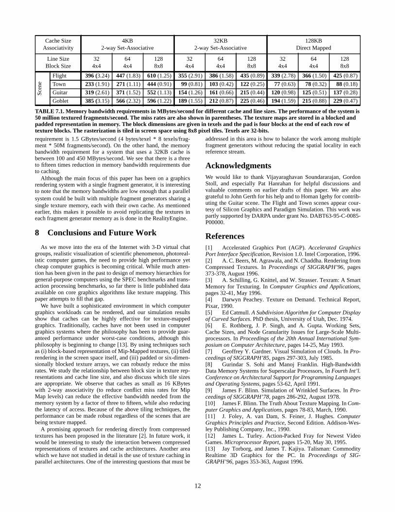
ates at peak bandwidth of 50 million textured fragments per sec-ond are shown in Table 7.1. We report results for three differentcache sizes: 4KB, 32KB, and 128KB. The 4KB cache is represen-tative of a very small on-chip cache. The 32KB cache is largeenough to hold the working sets, yet it can also be placed on-chip.Both the 4KB and 32KB caches are two-way set-associative. The128KB cache size provides a measure of how low the miss ratesand memory bandwidths can become if a very large cache is used.This cache is direct mapped since associativity makes little differ-ence in miss rates at this size. The results were measured for theblocked representation since we previously found this texture rep-resentation to be most suitable. In addition, the texture arrays arepadded and the rasterization in screen space is tiled to reduce con-flict misses and working set size.
One trend that can be seen in these results is that the memorybandwidth requirements are much reduced in the transition fromthe 4KB cache to the 32KB cache for all scenes except the Flightscene where the reductions are more modest. The transition to the128KB cache leads to less drastic reductions in memory band-widths demonstrating that fairly small cache sizes are adequate fortexture mapping. Another trend is that the memory bandwidthrequirements increase very slightly with increasing line size for the32KB and 128KB caches. This result is encouraging becauselarger line sizes can elicit a larger fraction of the peak memorybandwidth.
We would like to compare the memory bandwidth requirementsdiscussed above for a fragment generator that uses an SRAM tex-ture cache with the memory bandwidth requirement of a fragmentgenerator of equivalent performance that directly accesses a dedi-cated DRAM memory system for all texel lookups. For the lattersystem, which does not use a cache, the memory bandwidth
12
requirement is 1.5 GBytes/second (4 bytes/texel * 8 texels/frag-ment * 50M fragments/second). On the other hand, the memorybandwidth requirement for a system that uses a 32KB cache isbetween 100 and 450 MBytes/second. We see that there is a threeto fifteen times reduction in memory bandwidth requirements dueto caching.
Although the main focus of this paper has been on a graphicsrendering system with a single fragment generator, it is interestingto note that the memory bandwidths are low enough that a parallelsystem could be built with multiple fragment generators sharing asingle texture memory, each with their own cache. As mentionedearlier, this makes it possible to avoid replicating the textures ineach fragment generator memory as is done in the RealityEngine.
8 Conclusions and Future Work
As we move into the era of the Internet with 3-D virtual chatgroups, realistic visualization of scientific phenomenon, photoreal-istic computer games, the need to provide high performance yetcheap computer graphics is becoming critical. While much atten-tion has been given in the past to design of memory hierarchies forgeneral-purpose computers using the SPEC benchmarks and trans-action processing benchmarks, so far there is little published dataavailable on core graphics algorithms like texture mapping. Thispaper attempts to fill that gap.
We have built a sophisticated environment in which computergraphics workloads can be rendered, and our simulation resultsshow that caches can be highly effective for texture-mappedgraphics. Traditionally, caches have not been used in computergraphics systems where the philosophy has been to provide guar-anteed performance under worst-case conditions, although thisphilosophy is beginning to change [13]. By using techniques suchas (i) block-based representation of Mip-Mapped textures, (ii) tiledrendering in the screen space itself, and (iii) padded or six-dimen-sionally blocked texture arrays, we can robustly reduce the missrates. We study the relationship between block size in texture rep-resentations and cache line size, and also discuss which tile sizesare appropriate. We observe that caches as small as 16 KByteswith 2-way associativity (to reduce conflict miss rates for MipMap levels) can reduce the effective bandwidth needed from thememory system by a factor of three to fifteen, while also reducingthe latency of access. Because of the above tiling techniques, theperformance can be made robust regardless of the scenes that arebeing texture mapped.
A promising approach for rendering directly from compressedtextures has been proposed in the literature [2]. In future work, itwould be interesting to study the interaction between compressedrepresentations of textures and cache architectures. Another areawhich we have not studied in detail is the use of texture caching inparallel architectures. One of the interesting questions that must be
Cache SizeAssociativity
4KB2-way Set-Associative
32KB2-way Set-Associative
128KBDirect Mapped
Line SizeBlock Size
324x4
644x4
1288x8
324x4
644x4
1288x8
324x4
644x4
1288x8
Scen
e
Flight 396 (3.24) 447 (1.83) 610 (1.25) 355 (2.91) 386 (1.58) 435 (0.89) 339 (2.78) 366 (1.50) 425 (0.87)
Town 233 (1.91) 271 (1.11) 444 (0.91) 99 (0.81) 103 (0.42) 122 (0.25) 77 (0.63) 78 (0.32) 88 (0.18)
Guitar 319 (2.61) 371 (1.52) 552 (1.13) 154 (1.26) 161 (0.66) 215 (0.44) 120 (0.98) 125 (0.51) 137 (0.28)
Goblet 385 (3.15) 566 (2.32) 596 (1.22) 189 (1.55) 212 (0.87) 225 (0.46) 194 (1.59) 215 (0.88) 229 (0.47)
TABLE 7.1. Memory bandwidth requirements in MBytes/second for different cache and line sizes. The performance of the system is50 million textured fragments/second. The miss rates are also shown in parentheses. The texture maps are stored in a blocked andpadded representation in memory. The block dimensions are given in texels and the pad is four blocks at the end of each row oftexture blocks. The rasterization is tiled in screen space using 8x8 pixel tiles. Texels are 32-bits.
addressed in this area is how to balance the work among multiplefragment generators without reducing the spatial locality in eachreference stream.
AcknowledgmentsWe would like to thank Vijayaraghavan Soundararajan, GordonStoll, and especially Pat Hanrahan for helpful discussions andvaluable comments on earlier drafts of this paper. We are alsograteful to John Gerth for his help and to Homan Igehy for contrib-uting the Guitar scene. The Flight and Town scenes appear cour-tesy of Silicon Graphics and Paradigm Simulation. This work waspartly supported by DARPA under grant No. DABT63-95-C-0085-P00000.
References[1] Accelerated Graphics Port (AGP). Accelerated GraphicsPort Interface Specification, Revision 1.0. Intel Corporation, 1996.[2] A. C. Beers, M. Agrawala, and N. Chaddha. Rendering fromCompressed Textures. In Proceedings of SIGGRAPH’96, pages373-378, August 1996.[3] A. Schilling, G. Knittel, and W. Strasser. Texram: A SmartMemory for Texturing. In Computer Graphics and Applications,pages 32-41, May 1996.[4] Darwyn Peachey. Texture on Demand. Technical Report,Pixar, 1990.[5] Ed Catmull. A Subdivision Algorithm for Computer Displayof Curved Surfaces. PhD thesis, University of Utah, Dec. 1974.[6] E. Rothberg, J. P. Singh, and A. Gupta. Working Sets,Cache Sizes, and Node Granularity Issues for Large-Scale Multi-processors. In Proceedings of the 20th Annual International Sym-posium on Computer Architecture, pages 14-25, May 1993.[7] Geoffrey Y. Gardner. Visual Simulation of Clouds. In Pro-ceedings of SIGGRAPH’85, pages 297-303, July 1985.[8] Gurindar S. Sohi and Manoj Franklin. High-BandwidthData Memory Systems for Superscalar Processors, In Fourth Int’l.Conference on Architectural Support for Programming Languagesand Operating Systems, pages 53-62, April 1991.[9] James F. Blinn. Simulation of Wrinkled Surfaces. In Pro-ceedings of SIGGRAPH’78, pages 286-292, August 1978.[10] James F. Blinn. The Truth About Texture Mapping. In Com-puter Graphics and Applications, pages 78-83, March, 1990.[11] J. Foley, A. van Dam, S. Feiner, J. Hughes. ComputerGraphics Principles and Practice, Second Edition. Addison-Wes-ley Publishing Company, Inc., 1990.[12] James L. Turley. Action-Packed Fray for Newest VideoGames. Microprocessor Report, pages 15-20, May 30, 1995.[13] Jay Torborg, and James T. Kajiya. Talisman: CommodityRealtime 3D Graphics for the PC. In Proceedings of SIG-GRAPH’96, pages 353-363, August 1996.

13
[14] Kurt Akeley. RealityEngine Graphics. In Proceedings ofSIGGRAPH’93, pages 109-116, August 1993.[15] Lance Williams. Pyramidal Parametrics. In Proceedings ofSIGGRAPH’83, pages 1-11, July 1983.[16] L. Kohn, G. Maturana, M. Tremblay, A. Prabhu, and G.Zyner. Visual Instruction Set (VIS) in UltraSPARCTM. In Proceed-ings of COMPCON‘95, pages 462-469, March 1995.[17] Mark Segal, and Kurt Akeley. The OpenGL Graphics Sys-tem: A Specification, Version 1.0. Silicon Graphics, Inc., 1992.[18] M. F. Deering, S. A. Schlapp, and M. G. Lavelle. FBRAM:A new Form of Memory Optimized for 3D Graphics. In Proceed-ings of SIGGRAPH’94, pages 167-174, July 1994.[19] MMXTM Technology. Intel Architecture MMX TechnologyProgrammer’s Reference Manual. Intel Corporation, March 1996.[20] M. Segal, C. Korobkin, R. van Widenfelt, J. Foran, and P.Haeberli. Fast Shadows and Lighting Effects Using Texture Map-
ping. In Proceedings of SIGGRAPH’92, pages 249-252, July 1992.
[21] Ned Greene. Applications of World Projections. In Pro-ceedings of Graphics Interface ‘86, pages 108-114, May 1986.
[22] Paul Haeberli and Mark Segal. Texture Mapping as a Fun-damental Drawing Primitive. In Proceedings Fourth EurographicsWorkshop on Rendering, pages 259-266, June 1993.
[23] Paul S. Heckbert. Survey of Texture Mapping. In Proceed-ings of Graphics Interface ‘86, pages 207-212, May 1986.
[24] Steven A. Przybylski. New DRAM Technologies: A Com-prehensive Analysis of the New Architectures, Second Edition. Mi-croDesign Resources, 1996.
[25] W. T. Reeves, D. H. Salesin, and R. L. Cook. Rendering An-tialiased Shadows with Depth Maps. In Proceedings of SIG-GRAPH’87, pages 283-291, July 1987.
FIGURE 4.1. Flight scene
FIGURE 4.3. Guitar scene
FIGURE 4.4. Goblet scene
FIGURE 4.2. Town scene