the design and construction of hybrid soil nail/mse walls
TRANSCRIPT
The Design and Construction
of Hybrid Soil Nail/MSE Walls
John G. Delphia, P.E.
TxDOT Bridge Division
Geotechnical Branch
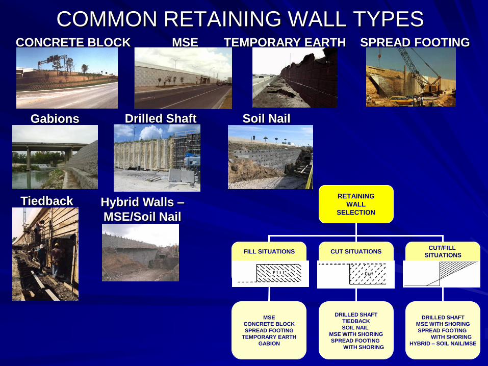
COMMON RETAINING WALL TYPESMSECONCRETE BLOCK TEMPORARY EARTH SPREAD FOOTING
Gabions Drilled Shaft
Tiedback
Soil Nail
Hybrid Walls –
MSE/Soil Nail
RETAINING
WALL
SELECTION
FILL SITUATIONS CUT SITUATIONSCUT/FILL
SITUATIONS
DRILLED SHAFT
TIEDBACK
SOIL NAIL
MSE WITH SHORING
SPREAD FOOTING
WITH SHORING
DRILLED SHAFT
MSE WITH SHORING
SPREAD FOOTING
WITH SHORING
HYBRID – SOIL NAIL/MSE
MSE
CONCRETE BLOCK
SPREAD FOOTING
TEMPORARY EARTH
GABION
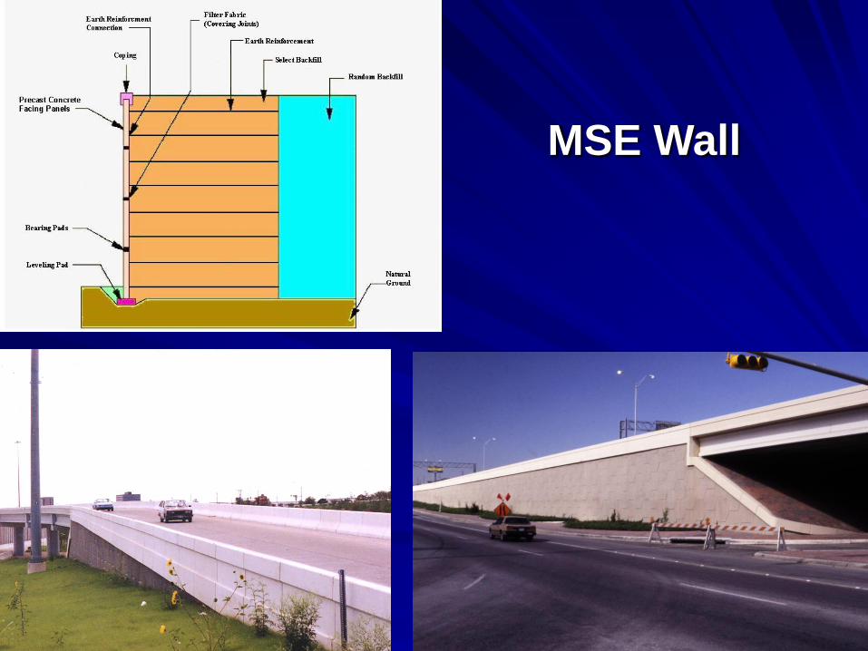
MSE Wall
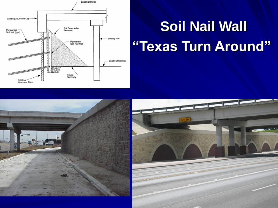
Soil Nail Wall
“Texas Turn Around”
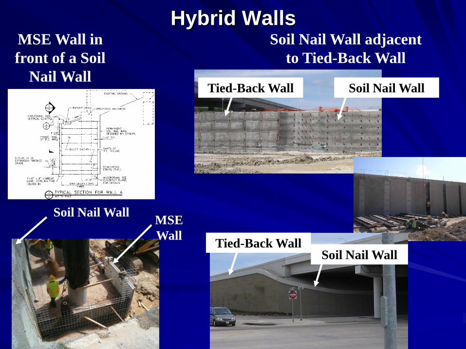
Hybrid WallsMSE Wall in
front of a Soil
Nail Wall
Soil Nail Wall adjacent
to Tied-Back Wall
Soil Nail WallMSE
Wall
Tied-Back Wall Soil Nail Wall
Tied-Back WallSoil Nail Wall
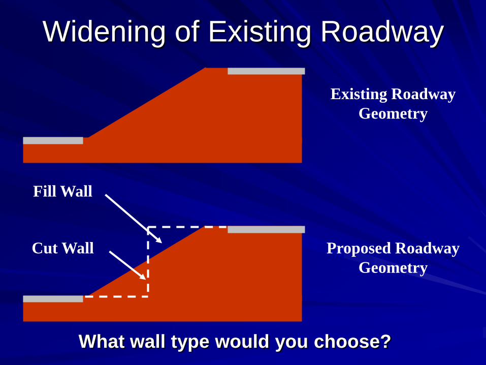
Widening of Existing Roadway
Fill Wall
Cut Wall
Existing Roadway
Geometry
Proposed Roadway
Geometry
What wall type would you choose?
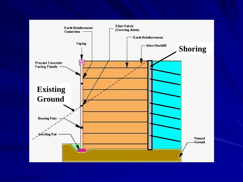
Shoring
Existing
Ground

HYBRID SOIL NAIL/MSE WALL
MSE (Fill) Wall on top of Soil Nail (Cut) Wall
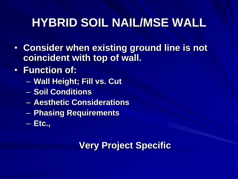
HYBRID SOIL NAIL/MSE WALL
• Consider when existing ground line is not coincident with top of wall.
• Function of:– Wall Height; Fill vs. Cut
– Soil Conditions
– Aesthetic Considerations
– Phasing Requirements
– Etc.,
Very Project Specific
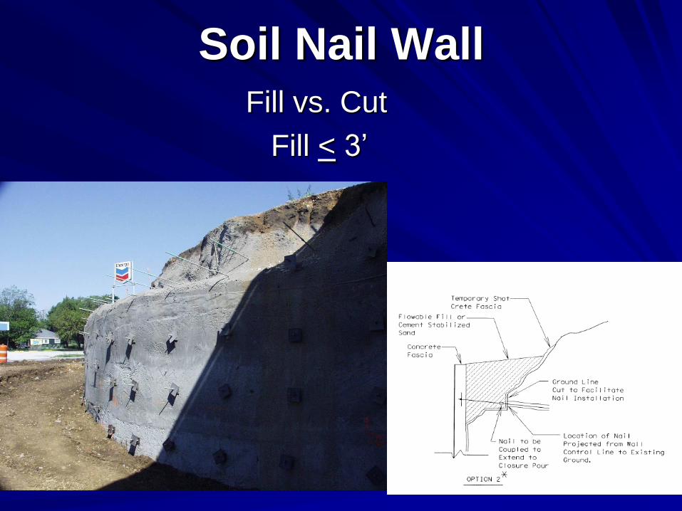
Soil Nail WallFill vs. Cut
Fill < 3’

Fill vs. Cut
Fill < 3’
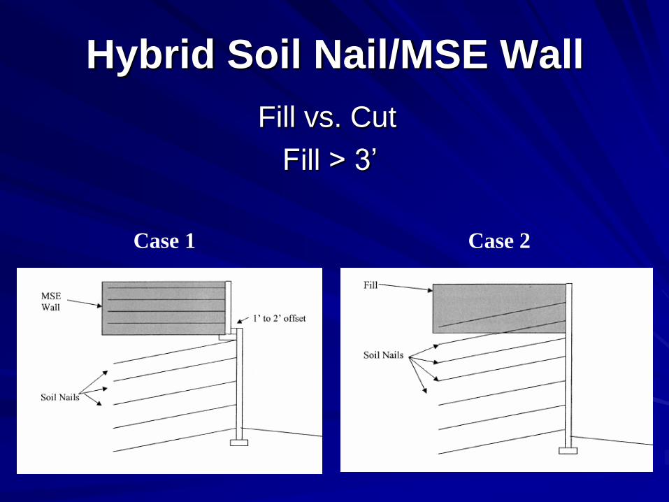
Hybrid Soil Nail/MSE Wall
Fill vs. Cut
Fill > 3’
Case 1 Case 2
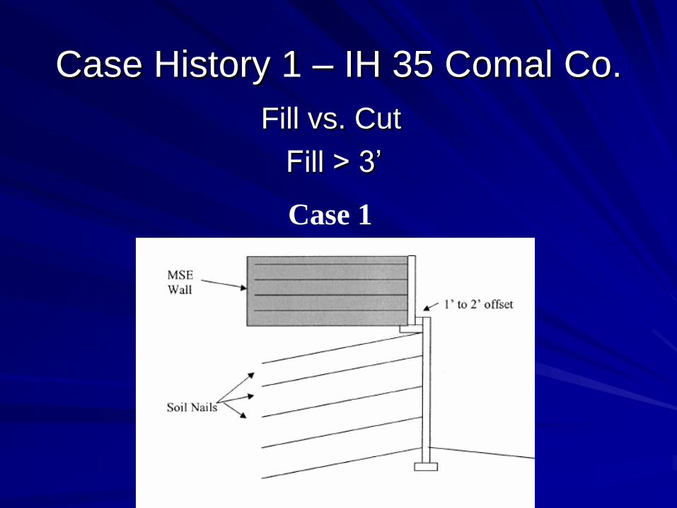
Case History 1 – IH 35 Comal Co.
Fill vs. Cut
Fill > 3’
Case 1
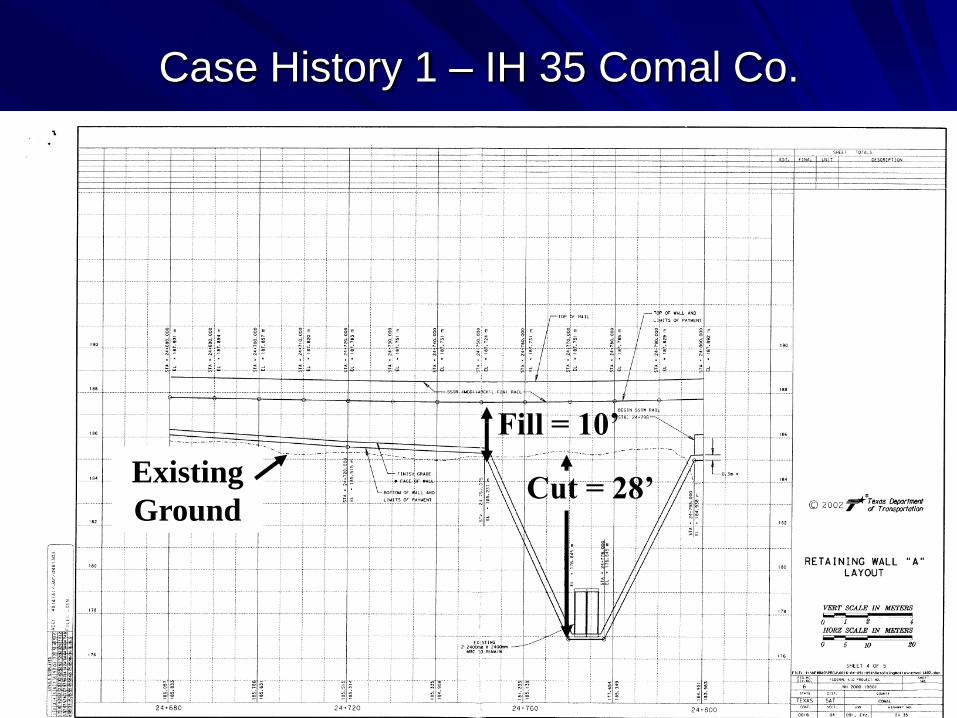
Case History 1 – IH 35 Comal Co.
Cut = 28’
Fill = 10’
Existing
Ground

• Establish wall geometry including bottom
of wall profile.
• Determine soil design parameters.
• Determine controlling loading condition
and appropriate analysis approach.
• Insure that the proposed wall geometry will
be globally stable.
Case History 1 – IH 35 Comal Co.
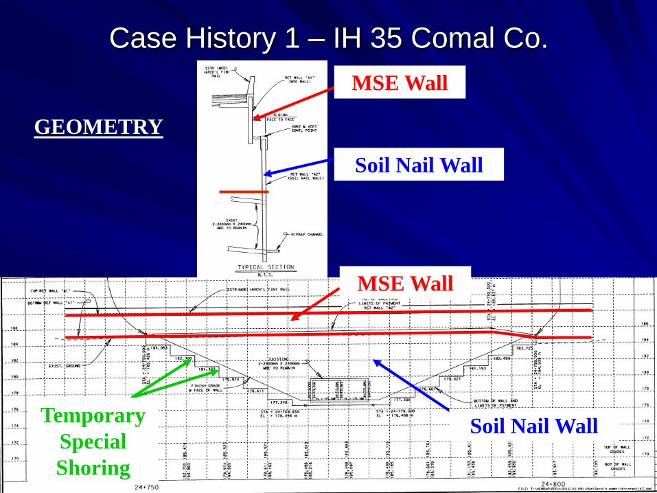
Case History 1 – IH 35 Comal Co.
MSE Wall
Soil Nail WallTemporary
Special
Shoring
Soil Nail Wall
MSE Wall
GEOMETRY
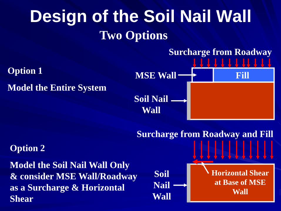
Design of the Soil Nail WallTwo Options
Option 1
Model the Entire System
Option 2
Model the Soil Nail Wall Only
& consider MSE Wall/Roadway
as a Surcharge & Horizontal
Shear
Surcharge from Roadway and Fill
Surcharge from Roadway
MSE Wall
Soil Nail
Wall
Fill
Soil
Nail
Wall
Horizontal Shear
at Base of MSE
Wall
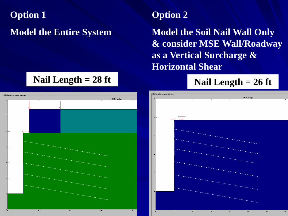
Option 1
Model the Entire System
Option 2
Model the Soil Nail Wall Only
& consider MSE Wall/Roadway
as a Vertical Surcharge &
Horizontal Shear
Nail Length = 28 ft Nail Length = 26 ft
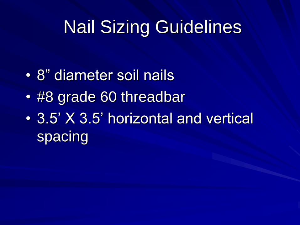
Nail Sizing Guidelines
• 8” diameter soil nails
• #8 grade 60 threadbar
• 3.5’ X 3.5’ horizontal and vertical
spacing
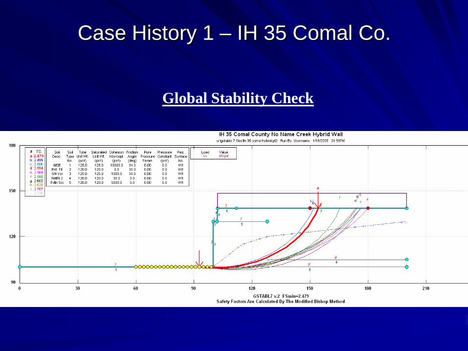
Case History 1 – IH 35 Comal Co.
Global Stability Check
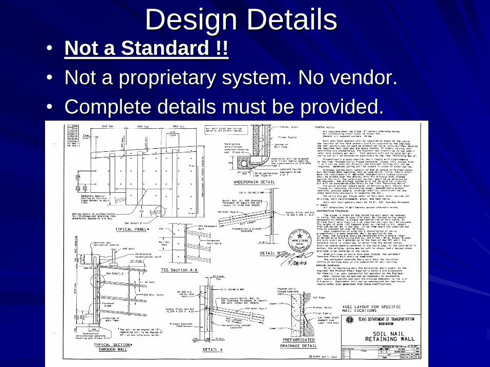
Design Details• Not a Standard !!
• Not a proprietary system. No vendor.
• Complete details must be provided.
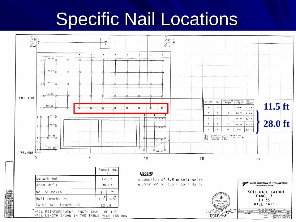
Specific Nail Locations
11.5 ft
28.0 ft
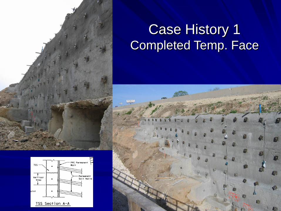
Case History 1Completed Temp. Face
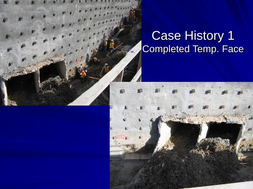
Case History 1Completed Temp. Face
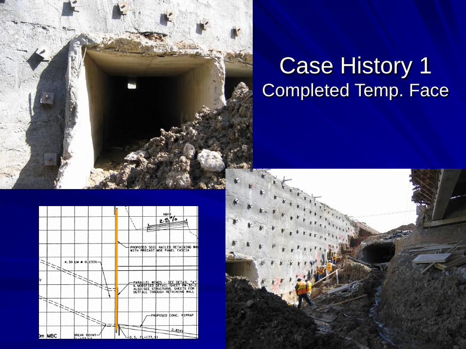
Case History 1Completed Temp. Face

Case History 1 Finished Wall – Precast Panel Fascia
Design Considerations
1. MSE Wall conflict with soil nails
2. Can a vertical wall face be used
instead of an offset wall face
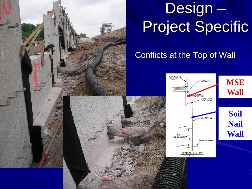
Design –
Project Specific
Conflicts at the Top of Wall
Soil
Nail
Wall
MSE
Wall
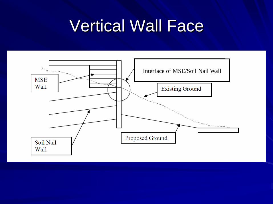
Vertical Wall Face
Interface of MSE/Soil Nail Wall
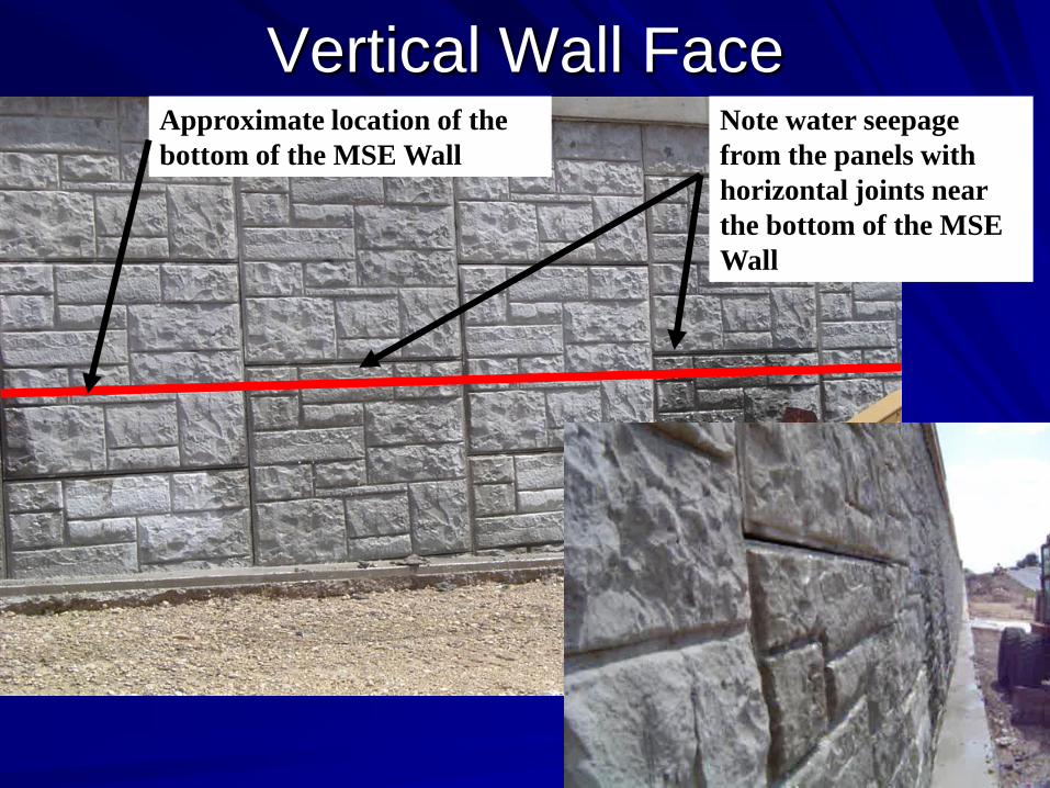
Vertical Wall FaceNote water seepage
from the panels with
horizontal joints near
the bottom of the MSE
Wall
Approximate location of the
bottom of the MSE Wall

Vertical Wall Face
Interface of MSE/Soil Nail Wall
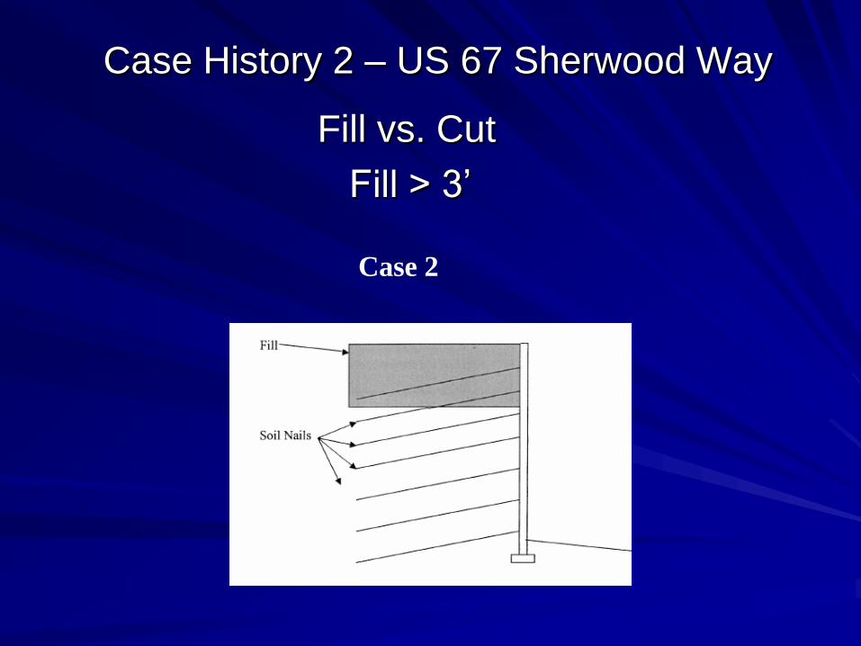
Case History 2 – US 67 Sherwood Way
Fill vs. Cut
Fill > 3’
Case 2
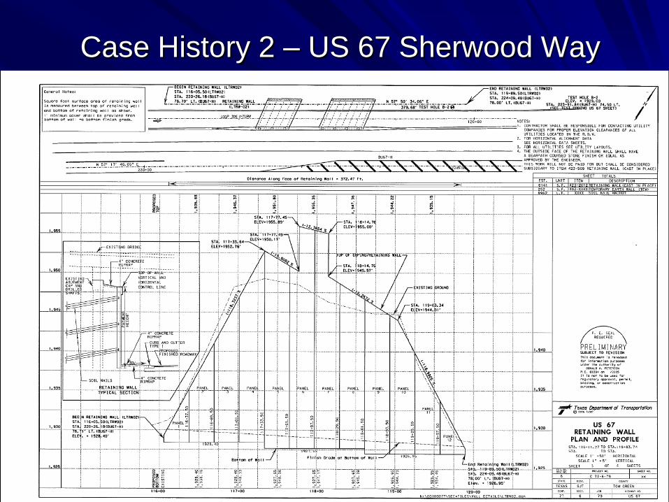
Case History 2 – US 67 Sherwood Way
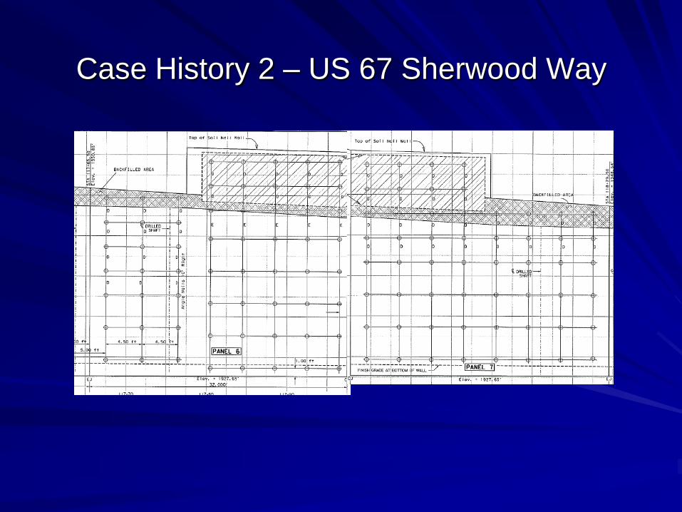
Case History 2 – US 67 Sherwood Way
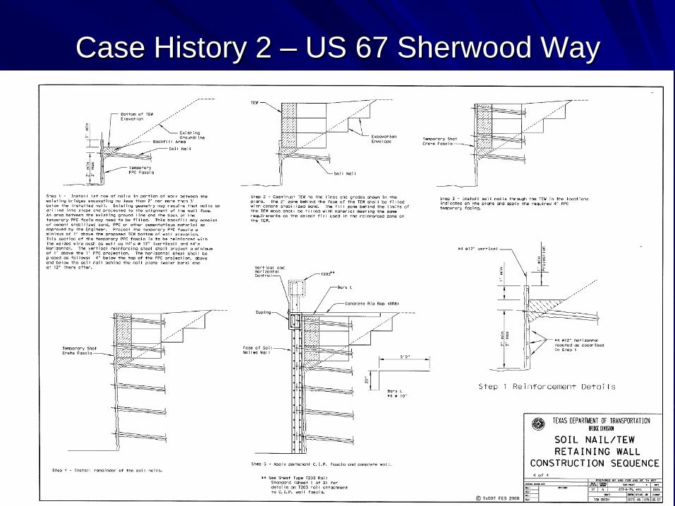
Case History 2 – US 67 Sherwood Way
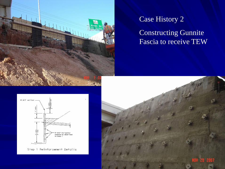
Case History 2
Constructing Gunnite
Fascia to receive TEW
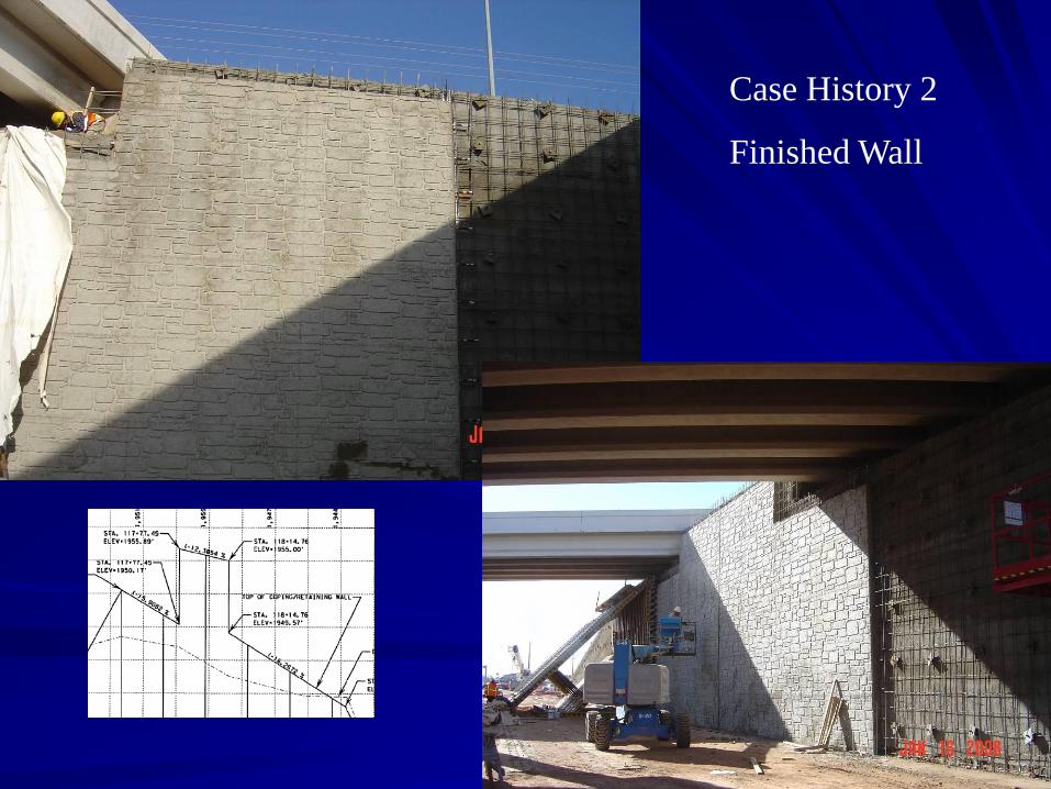
Case History 2
Finished Wall
HYBRID SOIL NAIL/MSE WALL
• Consider when existing ground line is not coincident with top of wall.
• Function of:– Wall Height; Fill vs. Cut
– Soil Conditions
– Aesthetic Considerations (facing options)
– Drainage
– Phasing Requirements
– Etc.,
– Very Project Specific
In Conclusion:

Questions?