the design and use of special purpose ... - purdue e-pubs
TRANSCRIPT
Purdue UniversityPurdue e-Pubs
LARS Symposia Laboratory for Applications of Remote Sensing
10-1-1973
The Design and Use of Special Purpose Processorsfor the Machine Processing of Remotely SensedDataG. R. AllenControl Data Corporation
L. O. BonrudControl Data Corporation
J. J. CosgroveControl Data Corporation
R. M. StoneControl Data Corporation
Follow this and additional works at: http://docs.lib.purdue.edu/lars_symp
This document has been made available through Purdue e-Pubs, a service of the Purdue University Libraries. Please contact [email protected] foradditional information.
Allen, G. R.; Bonrud, L. O.; Cosgrove, J. J.; and Stone, R. M., "The Design and Use of Special Purpose Processors for the MachineProcessing of Remotely Sensed Data" (1973). LARS Symposia. Paper 5.http://docs.lib.purdue.edu/lars_symp/5
Conference on
Machine Processing of
Remotely Sensed Data
October 16 - 18, 1973
The Laboratory for Applications ofRemote Sensing
Purdue UniversityWest Lafayette
Indiana
Copyright © 1973Purdue Research Foundation
This paper is provided for personal educational use only,under permission from Purdue Research Foundation.
THE DESIGN AND USE OF SPECIAL PURPOSE PROCESSORS
FOR THE MACHINE PROCESSING OF
REMOTELY SENSED DATA
G. R. Allen, L. O. Bonrud,J. J. CosgroveandR. M. Stone
Research Division, Control Data Corporation, Minneapolis, Mn.;Digital Image Systems Division, Control Data Corporation,
Minneapolis, Mn.; Control Data Corporation, Houston,Texas; Control Data Corporation, Houston, Texas
ABSTRACT
The processing of the expected volumes of remotely senseddata will overburden the available computer resources. One solution to the problem is the use of special purpose processors.This paper describes two such processors which are suitable forprocessing remotely sensed data. Also, examples of the .us e ofthe processors on specific problems encountered in remotelysensed data are described.
INTRODUCTION
The acquisition, processing and use of remotely sensed data is now evolving from a researchto a production activity. Thus, the volume of data to be processed will increase several fold.For example, it has been estimated that data rates of the order of 10 14 - 10 16 bits per year canbe expected in the near future. A data rate of 10 14 bits per year is equivalent to covering the surface of the earth every eighteen days in six spectral regions with a 200 foot digital sample step.The digital processing of this volume of data will generate a large computer requirement. Forexample, the processing of an ERTS image of 16 x 10 6 resolution elements on large scale gene~al purpose computers using the "LARSYS CLASSIFY" (Purdue, 1970) algorithm (4channels, 10classes) will require on the order of several hours of processing time.
This paper addresses the problem of reducing the above requirements through the use anddesign of special purpose processors. Several special purpose devices have been proposed in thepast for processing image data, the most ambitious being the ILLIAC III (Ramsey, 1968). However, special purpose devices (Kendall, 1971) have been used in several other areas such asseismic data and side looking radar processing.
The data volume problem occurred in the seismic data processing industry when the recording techniques changed from analog to digital. Digital recording allowed the use of moresophisticated processing techniques which in turn lead to the design and use of several types ofspecial purpose processors. All of these processors were connected to large computer mainframes and either used their own memories or shared mainframe memories. The early deviceswere hard-wired to perform multiply-add type operations. The devices have now advanced tosuch an extent as to be capable of performing a variety of tasks such as FFT, vector operations,weighting, filtering, etc. The latest versions of these devices are also programmable and can
lA-25
execute multiply-add operations on the order of 75 nanoseconds per operation.
The requirement for real-time change detection with side looking radar (SLR) imagery hasled to the development of special purpose digital processors capable of performing image matching, correlation, complex spatial transformations, photonomalization, computation of tonal difference i mage s , feature oriented processing and image enhancement. Again, the first processorswere hard-wired, but recent developments have led to the development of micro-programmable
processors.
This paper describes two special processors which have been developed for the processingof remotely sensed data. Examples of the use of these processors will include, the automaticregistration of ERTS multispectral scanner data, change detection and the classification of agri-
cultural resources.
SPECIAL PROCESSORS
Special purpose processors have been developed to increase the efficiency of data handlingwhere certain calculations are performed repetitiously. Such processors are very advantageouswhen large volumes of data must be processed, particularly when this data can be convenientlyorganized in array form. One such processor is the Matrix Algorithm Processor (MAP) whichwas originally developed to solve seismic problems. Another is the Flexible Processor (FP)which was specifically developed for digital image processing.
MA TRIX ALGORITHM PROCESSOR (MAP III)
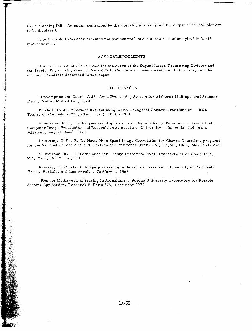
Earlier models of the Matrix Algorithm Processor were developed for seismic applications.The MAP III processor, which is currently being developed, is a microprogrammable device forthe high speed processing of arrays. Since the d~vice is programmable, the number of algorithmsthat can be executed is unlimited and any new algorithms can easily be incorporated. This provides the further advantage that the MAP III can be interfaced to various computers with minimumdesign changes. Its design features are summarized in the following:
• External Memory (24-256K)• Programmable• Floating Point (32-bits)
• Divide• Square Root• Multiply-Add• I/O Processor• Random Storage Addressing• Rela.ti ve Addressing• Macro Instructions• Looping of Macro Instructions• Interrupt of Macro Loops
The MAP III proces sor (Figure 1 ) consists of four functional units:
• the host computer interface• data storage• arithmetic units• control unit
The host computer interface consists of a data channel interface for transfer of control information and data with a second data source from a direct memory access if it is available withthe host system. The assembly/disassembly and conversion of data from fixed or floating pointto the floating point format internal to the MAP III arithmetic units is contained within this section. Also, a control panel and data input device are provided for off-line diagnostic capability.
The data storage section consists of three memories with separate control to allow
lA-26
simultaneous access to each memory. Memories A and B are both expandable from 8K to 96Kwhile memory C is expandable from 8K to 64K. The memories store a 32··bit word plus parity.Each memory has universal access to the data bussing structure to allow completely flexible useof each memory in the processing of matrix arithmetic problems.
The following arithmetic functions are provided for the calculation of the 32 bit floatingpoint data:
• Multiply• Divide• Add/ Subtract• Square Root
The arithmetic units receive input data from the two operand buses I and II or from the otherarithmetic units, as shown, with the result placed on the result bus for further manipulation orto be stored in memory. The arithmetic section can be expanded to allow for up to four multiply,two divide, four add/subtract, and two square root units.
The control unit is a microprogrammable device capable of manipulating the host computerinterface, data storage and arithmetic section of MAP III. The control memory will be constructed of semi-conductor ROM I/C's. This will allow the host computer to modify the micro-instruction sequence of the control unit, thus allowing flexibility for future algorithm developments. Thecontrol unit will also have the capabiHty to scan through a macro instruction list to allow the sameoperations on different data arrays.
The MAP III can operate at the following speeds:
• In the multiply unit, the product is available 150 nanoseconds after the operands areclocked into the unit (when multiple multiply units are us ed the multiply time is equalto 150 nanoseconds divided by the number of units).
• In the add/ subtract unit, the sum/ difference is available 150 nanoseconds after theoperands are clocked into the unit.
• In the divide unit, the quotient is available 1200 nanoseconds after the operands areclocked into the unit.
• In the square root unit, the square root is available 1800 nanoseconds after the operand is clocked into the unit.
The MAP III is programmed using a microcode assembler which generates microcode instruction routines through the specification of mnemonic instruction word fields and their corresponding values. Symbolic addressing is allowed. The use of an a s s ernbl'e r allows the microprogrammer to specify values for various fields within a word. Symbolic addressing allows theinsertion of new instruction words into the middle of an existing program without having to modifythe address fields for existing instructions that reference instructions which are moved upwardsby the insertion.
Algorithms can also be programmed as macro instructions which are collections of microinstructions. With this capability it is possible to string together sets of macro instructions.
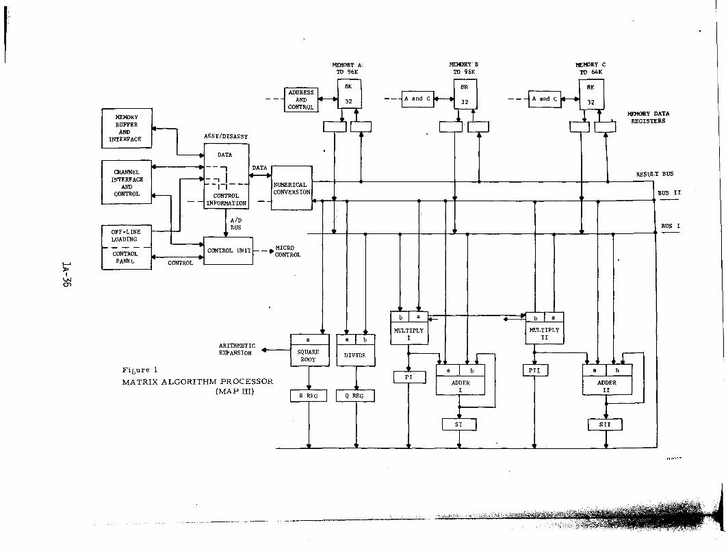
FLEXIBLE PROCESSOR
The Flexible Processor was developed for a large digital change detection system for concurrent processing of four channels of side-looking radar (SLR) imagery. Its name is derivedfrom its capability to be micro-programmed to solve a variety of array processing problems,such as sub-region matching, correlation, spatial transformation, photonormalization, photoequalization, difference image generation, and image enhancement. It will find application inmany image processing applications.
The flexible Processor is a special purpose computing unit which features high computationperformance and input-output capabilities ~s required for SLR image processing. olfhe logic organization and control mechanisms allow a range of computation, register file, microcontrol,
lA-27
I/O, and memory capability to be configured for specialized applications without disturbing thebasic mechanical and electrical wiring construction. The Flexible Processor (FP) is particularly effective in applications which require a high data throughput. The I/O structure is veryflexible and allows serial and parallel arrangements of FP's to work together on the processing
problem.
The unit fe a tur e s arithmetic logic capable of a O. 125 microsecond addition of 16-bit or32-bit operands, a 0.250 microsecond fixed point multiply of 8-bit bytes, and a 1. 25 microsecondfixed point multiply of 16-bit operands. The I/O structure provides for high speed file bufferedtransfers and for slower bus -oriented register biffered transfers. The FP is microprogrammableand uses random access semiconductor memory up to 1024 words of 48 bits each for microprogram control. A dual internal data bus system is used to match data transfer speed to the speedof arithmetic logic. Two 16-bit data buses route operands between the memory, computation andmicroprogram control memory units as shown in Figure 2. The main features of the FP aresummarized below:
• Microprogrammab1e - random access microcontrol memory• 32-bit or 16-bit word lengths• Array hardware multiplier• 16 level hardware priority interrupt mechanism - 4 mask registers• Conditional instruction execution - 4 condition and 4 mask registers• Specialized logic for square root and divide• 8 mHz file buffered word transfer rate - 16 word x 32 bit unput file buffer• 2 mHz register - buffered transfer rates• Dual 16-bit internal data bus system• 0.125 microsecond clock cycle• 0.125 microsecond 16-bit or 32-bit addition; 0.250 microsecond byte multiplication;
1. 25 microsecond 16-bit multiplication• Register file capacity up to 4160 bytes in several configurations of speed and size• Hardware network for conditional microinstruction execution
Four separate baIan ce d partyline transmission channels are' available (Figure 2). Each32-bit channel can initiate and receive register-buffered transfers. A scanning system allowsseveral FP's on a partyline to communicate with each other and with peripheral devices. Eachof the four partyline interfaces can communicate compatibly with other equipment. For maintenance purposes a forced transfer capability on the partyline is provided which allows an externaldevice (or another FP)"to force data into and out of an FP without the FP having any prearrangedprogramming.
For high speed data transmission (8 mHz) from one Flexible Processor to another, a 32bit output channel is provided which interfaces on balanced lines with 16 x 32 bit register files inreceiving FP's the 32-bit channel is composed of two 16-bit channels which have independent control mechanisms. The input register file of an FP can be written into only by another FP, not byitself. The receiving FP can READ its input file at the same time the sending FP WRITES thefile and can be connected to this high speed output channel.
The Flexible Processor is controlled by microinstructions held in a read/write 48 bit semiconductor memory which is expandable from 256 words to 1024 words. A new instruction can beexecuted every 125 n s e c s ; i. e. at an 8 mHz rate. Four categories of instructions used in themicroprogramming are transfer, transfer constant. shift, and I/O.
A 22 -bit portion of the 48 -bit microinstruction has the same format for each of the fourinstruction types. These 22 bits select the instruction type and control index register loadingand decrementing, multiplier input gating network add/ subtract, and logical operations. Theother 26 bits are used to control selection of operand source and destination for each of the twodata buses, control the shifting registers and control the input/output channels.
lA-28
IMAGE PROCESSING ALGORITHMS
Image processing algorithms can be broken down into two broad categories, algorithms toperform geometric corrections on the image data and algorithms to perform operations on theimage data itself. Examples of the latter are image enhancement involving the redistribution ofgray-scale values to effect a different tonal distribution, crop classification based upon gray-scalevalues, and change detection.
GEOMETRIC DISTORTIONS
Geometric corrections are required to produce an image which accurately represents apreselected projection and which registers point by point with another image of the same scene.The utilization of remotely sensed data typically requires that data values be obtained for thesame ground location from a number of images and in different spectral bands. Considering theanticipated work load, it is essential that automatic methods be established for obtaining accurateimage registration.
Image registration is complicated by a number of geometrical distortions. Among theseproblems are scaling, crab and drift, tilt induced displacement, relief displacement, displacementcaused by Earth's curvature, and radial lens distortion. Given the required data each of thesecorrections can be determined directly, but generally sufficient data is not immediately availablefor all of these factors. 'Other means must then be applied to eliminate any residual geometricaldistortions between images which are to be compared.
The complexity of the geometrical distortions are dependent upon the kind of imagery aswell as stability of the photographic platform and ground terrain. For example, roll and yaw inthe spacecraft platform will produce a continuously varying tilt displacement in the case of multispectral scanner imagery.
For a flying height of 832 kilometers (450 nautical miles) the tilt displacement is about 5cells at 92 kilometers (50 nautical miles) normal to the flight line when the tilt varies by 10 •
(The equivalent ground dimension of one cell is taken to be 76 meters or 250 feet). Manyapplications will require that two images be registered to within a few cells, and ideally, registrationshould be to within I cell if the data is to be most effectively used. Therefore, it can be concludedthat instability of the spacecraft platform can create significant distortions which must be corrected.
When the entire image is exposed simultaneously a single tilt angle applies to the imageframe, and the spatial correction is a simple linear function. But the tilt varies from one frameto the next and corrections are needed to register each image with a rectified image.
Elevation induced distortion is often insignificant for satellite imagery, but it can be significant where large changes in ground elevation occur. If a 20% grade should exist over a distanceof 3 kilometers (1. 6 nautical miles) at a distance of 92 kilometers from the nadir the resultingdistortion in the image is I cell over a distance of 3.3 millimeters (0. 13 inch). Scale =I: 1, 000, 000 and flying height = 832 kilometers . Thus, for such conditions interpolated spatialtransformations should be made on the basis of correlations every 3 millimeters (40 cells) ifdisplacement errors are to be held to I image cell. Elevation induced distortions are appreciablein underflight data, and it is important that corrections be made when underflight and overflightdata are correlated.
CORRELATION AND SPATIAL TRANSFORMATION
The general approach for deriving a spatial transformation to register two images of thesame scene is to determine the coordinates for a number of specific locations in both images andto create an interpolated transformation function satisfying these coordinate values.
For this discussion each image can be considered to be a rectangular array of the grayscale values at each cell location. The locations of corresponding image points i n-both imagescan be determined by placing an M by M window matrix in the independent image matrix and
lA-29
Values within the quadrilateral are selected by interpolation or by a nearest neighbor criterion.This method allows for hundreds of degrees of reeedom in the spatial warp.
Yet anothe r method is to effect a local quadrilateral transformation on four neighboringcorrelated points with a single analytic function j1) (u, v) where
A global map warp over the entire image can be created by a least squares polynominalapproximation. A maximum of about 40 degrees of freedom are practical with this method.
v = e + fx + gy + hxyu = a + bx + cy + dxy ;
Global or block processing techniques require large memories and are accordingly expensive.Another technique based upon recursive computation techniques (strip process) was developed inwhich the imagery is processed continuously with a line at a time from both images being read insimultaneously. A relatively small number of lines from the dependent image are updated in amodest memory, and a corrected scan line is read from this memory to correspond with thecurrent independent scan line. This method has the further advantage that it too provides hundredsof degrees of freedom.
The strip process is utilized in the pipeline digital change detection system which was builtfor the Air Force, and it is also used in a new change detection system which is under construction. The Flexible Processor as the building block for this new system is capable of solving thenumerous processing algorithms. The strip process technique has been applied successfully toa wide variety of side-looking-radar imagery and photographic imagery, as well as to the automatic registration of multispectral scanner imagery from the ERTS-l satellite (Figures 3,4).
moving another M by M window over the dependent image until the point of maximum similarityis found. An effective metric for measuring this similarity is the correlation coefficient.
INFORMATION EXTRACTION
In the process of extracting information from the gray-scale data it is often necessary toperform some kind of image enhancement, e. g., to minimize noise. Image enhancement techniques generally involve filtering of the image in either the space or transform domain. Both ofthese operations usually req.uire considerable computer effort. However, it is this type of welldefined operation that is suited to special processors. In fact, both the MAP III and the FlexibleProcessors can be configured to perform several of the transform techniques (i. e. Fourier,Walsh, Hadamard, etc.) which are commonly used.
Image detection techniques attempt to extract information from the image. Examples ofthis are edge detection, crop classification, etc. This type of operation usually requires a systematic scan ot the image and a calculation is done using each pixel. Classification techniquesalso require ground truth to determine statistical information which is in turn used to cla;sifythe image. As in the enhancement process, these techniques usually require considerable calculation. However, since the techniques are serial they are, again, well suited to special processors.
IMAGE PROCESSING EXAMPLES
Special purpose array processors serve the need for reducing the computing load on anexisting central computing system. The philosophy behind their development has been to performthe repetitious computations at high speed in the array processor and to use a general purposecomputer to supervise the process. Thus the design approach is toward a pipeline system. Asidefrom this specialized system approach the array processors can be added as peripherals to anexisting computer facility and greatly increase the production of that facility. Typical imageprocessing examples suitable for execution in special purpose algorithm processors are discussed in this section.
lA-3D
DIGITAL CHANGE DETECTION
Digital change detection has been successfully applied to side looking radar (SLR) reconnaissance (Lillestrand, 1972; Lam and Hoyt, 1972). In the Air Force system the process consists of simultaneous digitization of a dependent (mission) image and an independent (reference)image, matching, correlation, spatial warping (rectification), photonormali zation (transparencyrectification), generation of a difference image, and enhancement of the difference image.
The difference image for a SLR image pair will contain a certain quantity of noise in theform of spurious differences or "false alarms" in addition to the desired change events. Underoperational conditions reconnaissance flight paths may differ considerably. The false alarmproblem is also intensified because of shadow differences and scintillation, i . e., different radarreturns from the same feature caused by slightly different aspect angles. Under operational conditions the false alarm rate is typically 20-50%, excluding the effects of small random fluctuationsbetween independent and dependent images. These small random fluctuations caused by noisesources in the acquisition, photo processing and scanning of SLR imagery can be effectively suppressed by the nonlinear enhancement or thresholding techniques described in (Lilliestrand, 1972).The real problem is to develop a means of reducing the false alarm rate for the larger and moresystematic false alarms caused by scintillation and shadow differences without reducing the detection rate for legitimate changes.
One is tempted to use the same thresholding technique or some other form of gray-scaleprocessing because of its computational advantages. Gray-scale processing techniques do notutilize information about the spatial distribution of gray-scale or intensity values. These techniques are based solely on the joint distribution or "target classification diagram" (Lillestrand,1972) of intensity values on the independent and (digitally processed) dependent images. One canexploit the separation between the dis tr ibutions for legitimate changes and false alarms, thensuppress false alarms at minimal expense in terms of the detection rate for legitimate changes.Since these techniques tend to be very simple and require no knowledge of the spatial distributionof gray-scale values, they can be applied on a point-by-point basis as the difference image is generated.
For shadow-induced false alarms there is in general a distinct separation on the target classification diagram and gray-scale techniques are usually successful. Shadow intensity levels varyas a function of the scanning parameters and quality of the imagery, but are typically 0 to 6 or 8 ona six-bit scale. The mean background level on SLR imagery, on the other hand, is typically 14 to17. Thus, changes usually occur in backgrounds of significantly higher intensity than shadows anda simple thresholding technique (Lillestrand, 1972) and (Lam, 1972) can be effectively used forshadow suppression. The ability to bring two images into precise registration in real time makesdigital change detection applicable to a number "of image processing problems. Applications whichare currently being investigated include the following:
• Change detection of chest radiographs for clinical diagnosis• Precise registration of multispectral scanner imagery• Digital change detection for high resolution aerial photography·• Correlation of imagery from different sensors, particularly correlation of SLR with
aerial photography• Cartography, particularly derivation of elevation from stereo photographs.
The versatility of microprogrammable array processors in solving numerous image processing algorithms is illustrated with a particular application of the flexible processor in a digitalstereo mapping system (Figure 5). Numerical scanner control, correlation, spatial work, andphotonormalization are fundamental to change detection, as well as to mapping. (The numericalscanner control is responsible for utilizing the warp data to read a spatially corrected dependentimage). To these are added the functions of computation of elevation, feature extraction, andgeneration of an orthophotograph.
FEATURE ORIENTED PROCESSING
The assumption is made in feature oriented processing that the relative properties of
lA-31
features on the independent and dependent images for legitimate changes are significantly differentfrom those for false alarms. For a scintillarion-induced false alarm the same basic feature ispresent on both images with only minor differences, e. g .. in mean intensity or contrast. For aIe gi tim ate change, on the other hand, features on the independent and dependent.
For successful suppression of scintillation-induced false alarms some information about thespatial distribution of intensity values is necessary. In the feature oriented process intensities onthe independent and dependent images are compared over an area surrounding a given change eventThe change event is then classified using various statistical tests performed over this area. Themost significant test uses the correlation coefficient between the two images. Supplementary tests
are then performed on the mean intensity and contrast of both images, on the slope of the regression line and on the standard deviation of the joint distribution normal to the regression line. T'e stshave been made using SLR test imagery with side oblique photography for ground truth (Henrikson,1972). The classification error rate was 3 change events in 39 (8%), i , e., 92% of the change evertswere correctly classified. Moreover, of the 3 events incorrectly classified, only one was a twocell event while two were one-cell events. Thus in terms of total area, the classification errorwas only 4 pixels of 383 or 10/0, i. e., 99% of the change events on an area basis were correctlyclassified.
CLASSIFICA TION
This example will consider the implementation of the "CLASSIFY ALGORITHM" which isused in the LARSYS crop classification method (NASA, 1970). The classification algorithm whichis a maximum likelihood processor reduces to finding
Maxh
Where
~/2 (X - Mh)T Khl(X - Mh~ -------(1)
h number of classesX observation vector (n channels)
Mh mean ve ctor for the h th clas sKh-l= the inverse covariance matrix for the h t h class
Equation (1) can be rearranged to give
Max Sh
N
2:j = 1
j
~i = 1
dj ------(2)
Where n
d·1a··IJa ..
JJ
number of channelsi t h element of (X - Mh)ijth element of Kh: l (i T j)1/2 ajj element of Khl (i =j)
Now the problem reduces to a filtering problem which is suitable for solution on special purposealgorithm processors. If we let P equal the number of pixel elements to be processed and C thenumber of classes, then, the total number of multiples equals 1/2 PC (n 2 + 3n) and, the total number of adds equals 1/2 PC (n 2 + 3n). Thus, knowing the multiply and add times of the special processors, it is possible to calculate the total time required to classify a given area.
Implementation of Classify Algorithm Using Flexible ProcessorsThe following problem has been considered to demonstrate the capability of the flexible
processor. Classify an ERTS image of 16 x 10 6 pixels using 4 channels and 10 classes in 10 minutes. A flexible processor has the following characteristics:
• 125 nanosecond cycle time• 3 cycles / addition• 5 cycles / multiply
Thus if only one processor were used, the total processing time would be
lA-32
T = 8.33 x 10⁻⁹ x P x C (n Z + 3n) minutes
= 37.3 minutes
Now, if the processing were distributed over 10 processors, the time would be reduced to 3.73minutes, which is well within the required time. Figure 6 shows the hardware configuration using10 processors plus 1 supervisory processor. The software system will consist of two types ofprograms: the supervisor and the algorithm processor.
The SUPERVISOR program residing in FP No.1, the supervisor flexible processor, performs the following functions:
• Control the flow of data between the host computer and the flexible processor subsystem• Load all constant coefficients (K) into the flexible processor subsystem• Accomplish the final editing of the (5':') partial likelihood values computed in the line
flexible processors• Write each partial likelihood value (5':') and its class number back to the host computer
• Stimulate and synchronize the line flexible processors for one complete iteration• Buffer the pixel vectors (X) into the flexible processor subsystem.
The ALGORITHM program, residing in each of the line flexible processors, will performthe following functions under control of the SUPERVISOR program residing in the supervisorflexible processor:
• Fetch each pixel vector (X) from its predecessor flexible processor using the inputblock file
• Perform the a Igo r i thrn computations with pixel (X) and all of the constant (class) coefficients residing in that flexible processor
• Edit the partial likelihood values (5';') computed in that flexible-processor• Post flexible processor status to be monitored by the supervisor flexible processor.
It appears evident that the configuration is quite suitable for the processing of many other imageprocessing algorithms. Most of the image processing algorithms can be reduced to a series ofmultiply-adds which are capable of execution in such a parallel processing mode as that demonstrated in this configuration.
Matrix Algorithm Processor III (MAP III ImplementationUsing the same example as the one above, the MAP III which multiplies and adds at a 150
nanosecond rate (1 multiply-add unit) the ERTS image could be classified in 4.5 minutes, evenallowing for 100% program overhead, this would still be well under the 10 minute requirement.
For this application the constants such as the covariance inverse matrix and the mean vectors for each class would be stored in one of the MAP III memories. (Figure 1) The pixel datavector would be read into the other MAP III memory. The mean would be removed to yield thedj elements. Then the two filtering operations would be performed; the inner filter operationwould be performed first with the results being stored in the results memory. These resultswould then be filtered with the d j vector to produce S. Then the maximum S would be determined,thus giving the correct class to classify the pixel into. This process would be repeated forevery pixel on the image. It should be noted that the constant data would only be read to theMAP III memory initially.
REGISTRATION OF MULTISPECTRAL SCANNER IMAGERY
Multispectral scanner image data gathered by the ERTS-l satellite over Lake Somerville,Texas (Figure ) was automatically registered with the strip process technique. These arequarter frame images from Band 5 and represent an area 46 by 185 kilometers (25 by 100 nauticalmiles). Each image is composed of 2340 scan lines, each line having 700 elements reproducedin 64 gray-scale values.
The time interval between passes is 90 days, and extensive changes in the ground cover
lA-33
are evident north of the lake (Figure 3). These changes, as well as the clouds and cloud shadows decrease the correlation considerably. However, it was possible to minimize the effect ofclouds and their shadows by applying a threshold to the gray-scale data.
A tonal difference image was created by subtracting each dependent image gray-scale valuefrom the corresponding independent image value (Figure 3 ). Changes are emphasized by digitally i nc r e a s i ag the contrast of the middle tones in this difference image. Clouds, on the otherhand, are de-emphasized as explained above. It is possible to recover the cloud changes eitherby storing the threshold data or by applying the derived spatial transformation to the original dependent data, with which a difference image can be created to represent all changes. Such selective processing is very usefuL
Despite the clouds and other extensive changes the process (which began at the top or northend) maintained registration generally within one cell. This is demonstrated by superimposingthe spatial gradient of the independent image upon the warped dependent image (Figure 4 - magnified section).
Spatial distances along the flight path are consistent to within 2 image elements, indicatingvery uniform velocity and little pitch and yaw. There was, however, an additional translationof 26 elements in the image data files, but this was readily corrected with the automatic processing. Warp vector components normal to the flight direction were not as consistent, varyingfrom 2 to 21 elements in length. Such displacements are considered significant when remote sensing signatures are constructed.
PHOTONORMALIZA TION WITH THE FLEXIBLE PROCESSOR
The photonormalization process adjusts the gray-scale values of the dependent image sothat its tonal values match the independent image. This is done to eliminate from the tonal difference image those changes which would occur due to differences in illumination and processingvariables. Typically the required corrections are generated from computations of the averagevalue and standard deviation of gray-scale values. These corrections are made continuously overthe entire image area as the warp is applied.
This example demonstrates the use of the Flexible Processor in implementing the photonormali zation function.
The calculation is, AN
Where ACD
AN
AxC+D
gray-scale value of dependent pixelcontrast correction factordensity correction factorgray-s cale value of the normalized dependent pixel
In the correlator the calculations needed to produce new C and D factors are performed bylogic sections other than the photonormalization section. The photonormalization logic sectionimplements the above equation and then proceeds with change detection and image enhancementfunctions. The Flexible Processor was programmed to match the operations carried our by thephotonormalization logic section of the Change Detection Correlator.
Photonormali zation ProgramGray-scale correction occurs early in the photonormalization program at step 9 (Figure 7).
The adjusted dependent and independent pixel values are then subtracted to form the difference.The difference operand is compared with thresholds, DHTand DLT (from flow chart), to determine whether or not a real change is present. The pixel magnitudes are also compared with athreshold, DST which is used to suppress shadows from being labeled as changes. If none of thethresholds are exceeded, the output will be one of three background modes: independent, dependent, or tonal difference image.
It is desirable, as in the case of the tonal difference image, which is generally fiat and hasvery little contrast, to expand the range of its gray-scale values. This is accomplished by
lA-34
L
(K) and adding (M). An option controlled by the operator allows either the output or its complemert
to be displayed.
The Flexible Processor executes the photonormalization at the rate of one pixel in 3.625
micros econds.
ACKNOWLEDGEMENTS
The authors would like to thank the members of the Digital Image Processing Division andthe Special Engineering Group, Control Data Corporation, who contributed to the design of thespecial processors described in this paper.
REFERENCES
"Description and User's Guide for a Processing System for Airborne Multispectral ScannerData", NASA, MSC-01646, 1970.
Kendall, P. Jr. "Feature Extraction by Golay Hexagonal Pattern Transforms". IEEETrans. on Computers C20, (Spet. 1971), 1007 - 1014.
Henrikson, P. J., Techniques and Applications of Digital Change Detection, presented atComputer Image Processing and Recognition Symposium, University - Columbia, Columbia,Missouri, August 24-26, 1972.
Larn vMaj. C. F., R. R. Hoyt, High Speed Image Correlation for Change Detection, preparedfor the National Aeronautics and Electronics Conference (NAECON), Dayton, Ohio, May 15-17,1972.
Lillestrand, R. L., Techniques for Change Detection, IEEE Transactions on Computers,Vol. C-21, No.7, July 1972.
Ramsey, D. M. (Ed.), Image processing in biological science. University of CaliforniaPress, Berkeley and Los Angeles, California, 1968.
"Remote Multispectral Sensing in Ariculture", Purdue University Laboratory for RemoteSensing Application, Research Bulletin 873, December 1970.
lA-35
MEMO~Y'; ATO 96K
MEK>RYBTO 96K
MEK>RY CTO 64K
BUS
BUS I
BUS II
'ATARS
..--- r----8K
.--,1ADDRESS}---8&
- - AND ---{~ and C~8K
32 A and C1----+CONTROL
32 --MEMORY
- 32
BUFFER --AND
MEMORY D
INTERFACE ASSY!DISASSY
REGISTE
~
.... DATA.
1-
CHANNEL-.. --, DATA
INTERFACE ~ -.., I ..--.AND I-- n - - - NUMERICAL
CONTROL ~
RESUL1
CONTROL CONVERSION- -' INFORMATION --
IAID
OFF-LINEBUS
LOADING.. ,
~----CONTROL CONTROL UNIT I- _.MICRO
PANEL CONTROL --.CONTROL
, ..b a - b 1 a4-------::!:
, MULTIPLYa a b I
MULTIPLY
-II
SQUARE DIVIDE1
ROOT 1 r: crliJ 1 r-~ a I
ORPI
b I bIa
IADDER
R REG 1 Q REGI
ADDER
1II
1
~ rI SI 1 1
1SII
~»I
\.NO"l
n?fl~7
2
o
D20t:i
lA-37
INPUTFILE ...
~32 ~ AQ3... • 32
~ 16 words >-ww • 32~AQ
t- 2 2 • ~ AQ 1x ~_2 3232 bits ...Jet .. AQ
Q. ~
SMALL C...JFILE CWw- J: 0:2
16 words -.. (,:)ttJ W 2... . - -Q.u- et 32J:cnu-J:x~u
..32 bits
...
LARGE PRIORITYFILE INTERRUPT
1024w .. NETWORKx -
32 bits..
,
CONDITIONAL- . INSTRUCTION..
NETWORKARITH-METICLOGIC ..UNIT MICROMEMORY
32 bits ..CONTROLNETWORK
16 161024 w x 48 b
MULTI-PLIER .
-...16 bit ...-
results
Figure 2
FLEXIBLE PROCESSOR

• b
Figure 3
AUTOMATIC REGISTRATION OF MULTISPECTRAL SCANNER IMAGERYa] Independent Im a ge . b) Dependent Image , c) Diffe rence (Emphasized)
lA-38
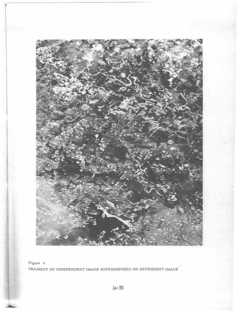
Figure 4
GRADIENT OF I NDE PE NDE NT IMAGE SUPERIMPOSED ON DEPENDENT IMAGE
..
lA-39
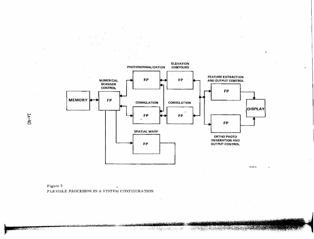
ElEVATIONPHOTONORMALIZATION CONTOURS
.......»I
.J::"C>
NUMERICAL -. F.P .... FP It-SCANNER 4-CONTROL
~ FP
le-~ JMEMORY .-. FP
CORRELATION CORRELATION
~DISPLAY•
~FP ...... FP
j.FP4
ISPATIAL WARP
.- FP
O?OHi
Figure 5
FLEXIBLE PROCESSOR IN A SYSTEM CONFIGURATION
t '$\ I , 'I I .1'- n' 'H" "'"" I,d "·,,,,,;"I'r"71' jl'! 'Ii !rf''illtiJiM\~,fH'.,,'v, -.,~ ,,.4'1'~" ,,"',~",o'i,
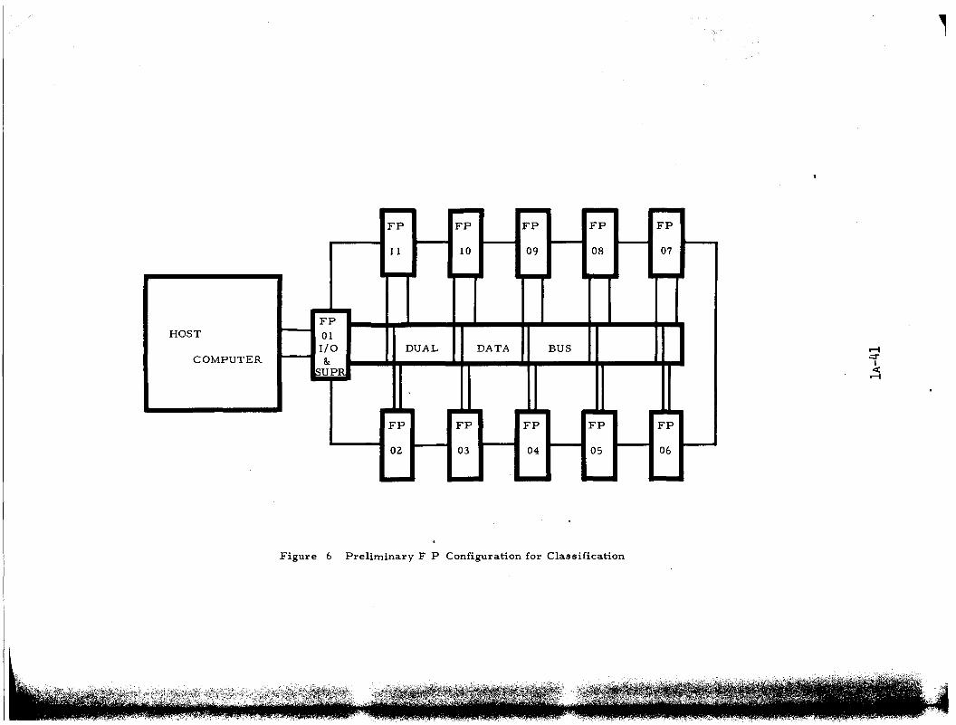
FP FP FP FP FP
11 10 09 08 07
FPHOST 01
I/O DUAL DATA BUSCOMPUTER &.
SUPR
.• • . ..
FP FP FP FP FP
02 03 04 05 06
-Figure 6 Preliminary F P Configuration for Classification
~.:::r
Ic:(~
,
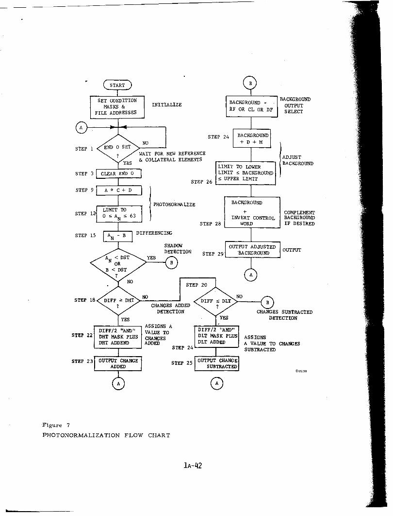
OUTPUT
COMPLEMENTBACKGROUNDIF DESIRED
ADJUSTBACKGROUND
BACKGROUNDOUTPUTSELECT
02038
ASSIGNSA VALUE TO CHANGESSUBTRACTED
BACKGROUND
+INVERT CONTROL
WORD
BACKGROUND RF OR CL OR DF
o
STEP 24
STEP 29 L..-__-,- -1
STEP 28
DIFF/2 "AND"DLT MASK PLUSDLT ADDED
LIMIT TO LOWERLIMIT s; BACKGROUND
STEP 26 s; UPPER LIMIT
STEP 24 L..-----,r------..J
STEP 25
PHOTONORMA LIZE
lA-42
CHANGES ADDEDDETECTION
INITIALIZE
NO
WAIT FOR NEW REFERENCE& COLLATERAL ELEMENTS
DIFF/2 "AND"DRT MASK PLUSDRT ADDEND
SET CONDITIONMASKS &
FILE ADDRESSES
,.---.......--.-, ASSIGNS AVALUE TOCHANGESADDED
STEP
STEP
STEP 23
STEP 22
F'Igur e 7
PHOTONORMALIZATION FLOW CHART
•