the design and validation of a computational model …
TRANSCRIPT

Virginia Commonwealth UniversityVCU Scholars Compass
Theses and Dissertations Graduate School
2013
THE DESIGN AND VALIDATION OF ACOMPUTATIONAL MODEL OF THEHUMAN WRIST JOINTAfsarul MirVirginia Commonwealth University
Follow this and additional works at: http://scholarscompass.vcu.edu/etd
Part of the Biomedical Engineering and Bioengineering Commons
© The Author
This Thesis is brought to you for free and open access by the Graduate School at VCU Scholars Compass. It has been accepted for inclusion in Thesesand Dissertations by an authorized administrator of VCU Scholars Compass. For more information, please contact [email protected].
Downloaded fromhttp://scholarscompass.vcu.edu/etd/3058

© Afsarul Q. Mir, 2013
All Rights Reserved
THE DESIGN AND VALIDATION OF A COMPUTATIONAL MODEL OF THE
HUMAN WRIST JOINT
A Thesis submitted in partial fulfillment of the requirements for the degree of Master of
Science at Virginia Commonwealth University.
by
AFSARUL QUDDUS MIR
B.S., Virginia Commonwealth University, 2009
Director: Jennifer S. Wayne, Ph.D.
Departments of Biomedical Engineering and Orthopaedic Surgery
Virginia Commonwealth University
Richmond, Virginia
May, 2013

ii
Acknowledgement
Looking back at my academic career at VCU, there a number of people that I would like
to acknowledge and thank for all their help and support.
First and foremost, I would like to express my sincerest gratitude to my advisor and
mentor, Dr. Jennifer Wayne. Starting from my undergraduate years at VCU and all through my
graduate work, you have provided the support and guidance that has been critical in my
academic and professional success. Your guidance has always forced me to reach above and
beyond in everything that I do. Your input and insight has been invaluable for all the work that I
have conducted in the Orthopaedics Research Laboratory. Working for you in various manners
over the past six years has been an honor and I am very grateful for all the opportunities you
have provided. Much of my professional growth has occurred under your care and I will carry
those lessons with me through the rest of my life.
I would also like to thank Dr. Gerald Miller and Dr. Jonathan Isaacs for taking the time to
serve on my thesis advisory committee. I greatly appreciate all the comments and feedback you
have provided throughout the various stages of my work.
Next, I would like to extend my thanks to all my friends and peers that I have worked
with while completing my graduate work. Meade, Sean, Ruchi, Johnny, Erika and Casey, thank
you for all your support. You have made my time in the lab much more memorable. And a very
special thanks to Meade and Ruchi, for all your help, advice and support throughout my thesis
work. Without the two of you, things would have been much more difficult.
And finally, I would like to thank my family, without them I would not be here today. To
my little brother, Sayem, it has been a privilege being your older brother and you have brought
great joy to me with all your quirky ways. To my older brother, Ceasar, you have been beside
me every step of my life. Thank you for always “having my back” and supporting me every
single day. And to my mother, Mohsina, you have been the source of my drive. Even from afar,
you have been my inspiration and reassurance when things got tough. Thank you for all your
love and support.
iii
Table of Contents
Page
Acknowledgements..................................................................................................................... ii
List of Tables.............................................................................................................................. vi
List of Figures............................................................................................................................ vii
List of Abbreviations................................................................................................................. xii
Abstract..................................................................................................................................... xiv
1. INTRODUCTION............................................................................................................ 1
1.1 OVERVIEW OF MUSCULOSKELETAL TESTING.............................................. 1
1.1.1 Musculoskeletal Testing Methods...................................................................... 1
1.2 COMPUTATIONAL MODELING OF MUSCULOSKELETAL SYSTEMS......... 3
1.2.1 Types of Modeling............................................................................................. 3
1.2.2 Finite Element Analysis..................................................................................... 3
1.2.3 Rigid Body Modeling......................................................................................... 4
1.2.4 Existing Wrist Rigid Body Models..................................................................... 7
1.3 OBJECTIVES............................................................................................................11
2. WRIST ANATOMY....................................................................................................... 12
2.1 SKELETAL ANATOMY......................................................................................... 14
2.2 SOFT TISSUE ANATOMY....................................................................................17
2.2.1 Ligamentous Anatomy...................................................................................... 18
2.2.2 Triangular Fibrocartilage Complex................................................................ 24
2.2.3 Muscular Anatomy........................................................................................... 27
iv
2.2.4 Retinacular Anatomy........................................................................................30
3. THREE-DIMENSIONAL WRIST MODEL FORMULATION.................................... 35
3.1 OVERVIEW............................................................................................................. 35
3.2 COMPUTED TOPOGRAPHY OF THE WRIST.................................................... 35
3.3 THREE-DIMENSIONAL BODY CREATION...................................................... .37
3.3.1 Mask Creation.................................................................................................. 37
3.3.2 Mask Refinement.............................................................................................. 39
3.3.3 3D Mesh Creation and Remeshing.................................................................. 44
3.3.4 STL Files and SolidWorks................................................................................ 48
3.4 SOLIDWORKS AND ASSEMBLIES..................................................................... 49
3.5 SOLIDWORKS MOTION....................................................................................... 50
3.6 LIGAMENT STRUCTURES................................................................................... 52
3.6.1 Origins and Insertions..................................................................................... 52
3.6.2 Ligament Mechanical Properties................................................................... ..57
3.7 TRIANGULAR FIBROCARTILAGE COMPLEX................................................. 61
3.8 CAPSULAR RETINACULAR STRUCTURES..................................................... 65
3.9 WRIST MUSCLES.................................................................................................. 69
3.10 COMPLETE 3D WRIST MODEL........................................................................... 72
4. RSL RANGE OF MOTION VALIDATION STUDY................................................... 73
4.1 OVERVIEW............................................................................................................. 73
4.2 RSL WRIST RANGE OF MOTION STUDY..........................................................73
4.3 COMPUTATIONAL MODELING OF RSL RANGE OF MOTION STUDY....... 75
4.4 RESULTS................................................................................................................. 79
v
5. BIOMECHANICS OF THE WRIST FOLLOWING PROXIMAL ROW
CARPECTOMY............................................................................................................ 89
5.1 OVERVIEW........................................................................................................... 89
5.2 PROXIMAL ROW CARPECTOMY EXPERIMENTAL STUDIES..................... 90
5.3 COMPUTATIONAL MODELING OF PROXIMAL ROW CARPECTOMY
STUDIES………………………………………………………………………...…94
5.4 RESULTS.............................................................................................................. 110
6. DISCUSSION............................................................................................................... 125
7. CONCLUSION……………………………………………………………………..... 139
LITERATURE CITED……………………………………………………………………141
VITA……………………………………………………………………………………... 148
vi
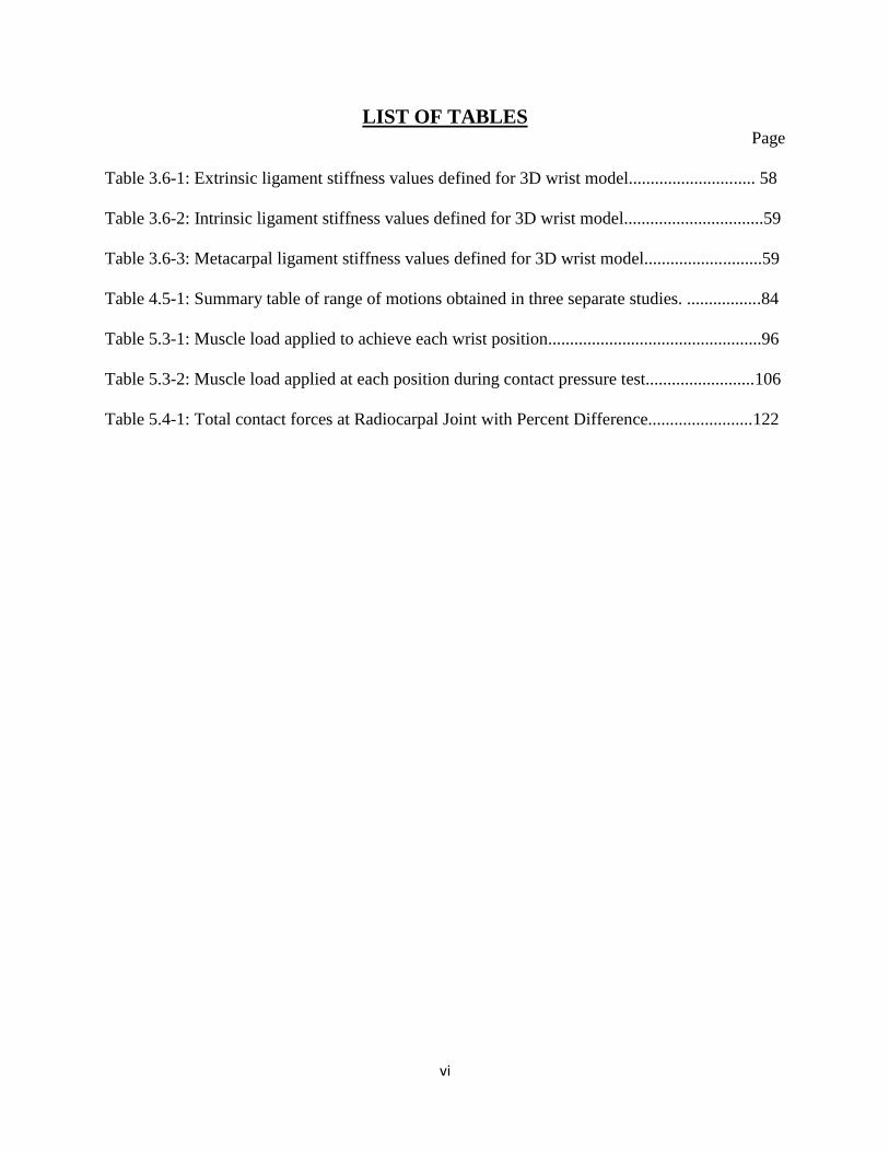
LIST OF TABLES Page
Table 3.6-1: Extrinsic ligament stiffness values defined for 3D wrist model............................. 58
Table 3.6-2: Intrinsic ligament stiffness values defined for 3D wrist model................................59
Table 3.6-3: Metacarpal ligament stiffness values defined for 3D wrist model...........................59
Table 4.5-1: Summary table of range of motions obtained in three separate studies. .................84
Table 5.3-1: Muscle load applied to achieve each wrist position.................................................96
Table 5.3-2: Muscle load applied at each position during contact pressure test.........................106
Table 5.4-1: Total contact forces at Radiocarpal Joint with Percent Difference........................122

vii
LIST OF FIGURES
Page
Figure 2-1: Anatomical regions and wrist motions around the indicated axes (palmar view of the
right wrist)....................................................................................................................... 13
Figure 2.1-1: Skeletal anatomy of the wrist and hand (palmar view of the right wrist)............. 14
Figure 2.1-2: The joints of the wrist (palmar aspect of the right wrist)...................................... 15
Figure 2.2-1: Palmar ligaments of the wrist............................................................................... 20
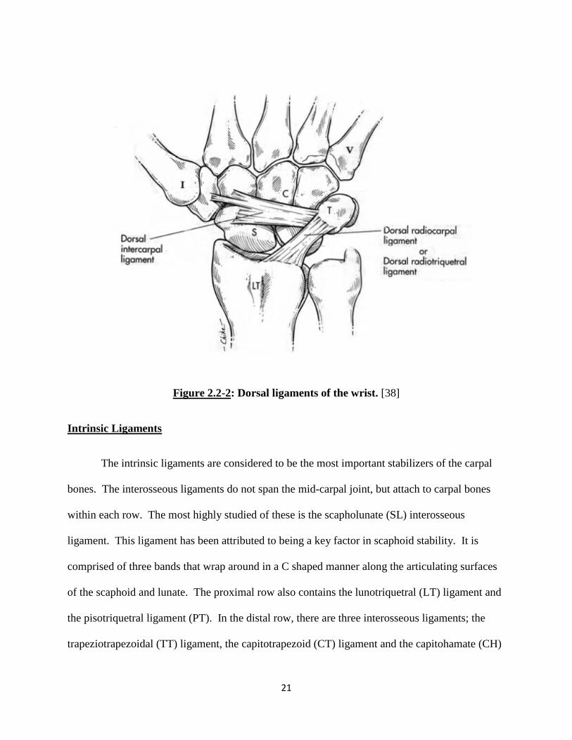
Figure 2.2-2: Dorsal ligaments of the wrist................................................................................ 21
Figure 2.2-3: Palmar intrinsic ligaments of the wrist................................................................. 23
Figure 2.2-4: Dorsal intrinsic ligaments of the wrist.................................................................. 23
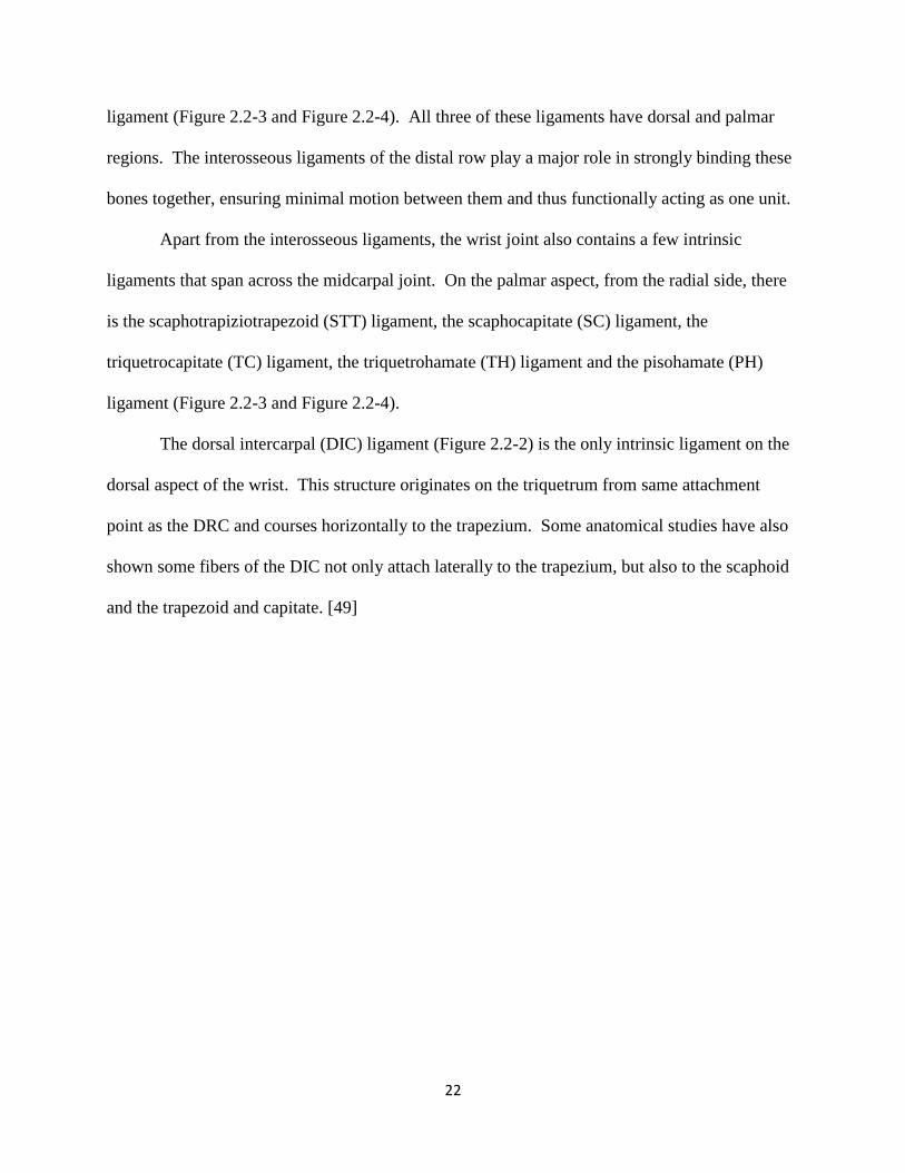
Figure 2.2-5: Cross-sectional view of the proximal wrist highlighting soft tissue components of
the TFCC........................................................................................................................ 25
Figure 2.2-6: Ligaments of the forearm and wrist integrated with the TFCC............................ 25
Figure 2.2-7: Schematic of the structural components of the TFCC......................................... 26
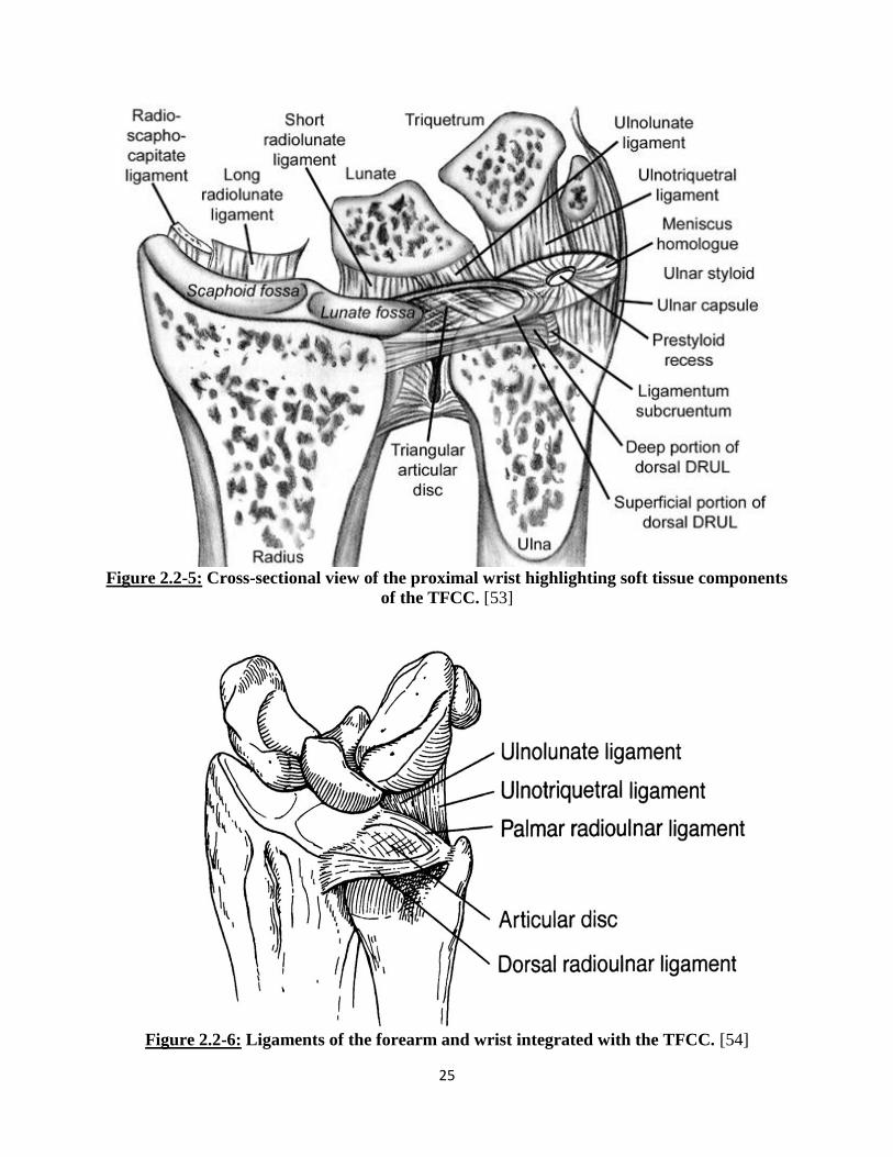
Figure 2.2-8: Flexor Muscles of the wrist joint....................................................... ..................28
Figure 2.2-9: Extensor Muscles (highlighted green) of the wrist joint...................................... 29
Figure 2.2-10: Drawing demonstrating the three portions of the flexor retinaculum................. 32
Figure 2.2-11: Dorsal aspect of hand showing extensor retinaculum (top) and cross-sectional
view of extensor retinaculum compartments (bottom)………………………………... 33
Figure 2.2-12: Cross-sectional view of the distal radioulnar joint showing the compartments of
the extensor retinaculum………………………………………………………………. 34
Figure 3.2-1: Cadaveric specimen used for wrist model formulation………………………….36
Figure 3.3-1: Thresholding tool used to select osseous structures with standard range (left) and
redefined threshold range (right)………………………………………………….……38
viii
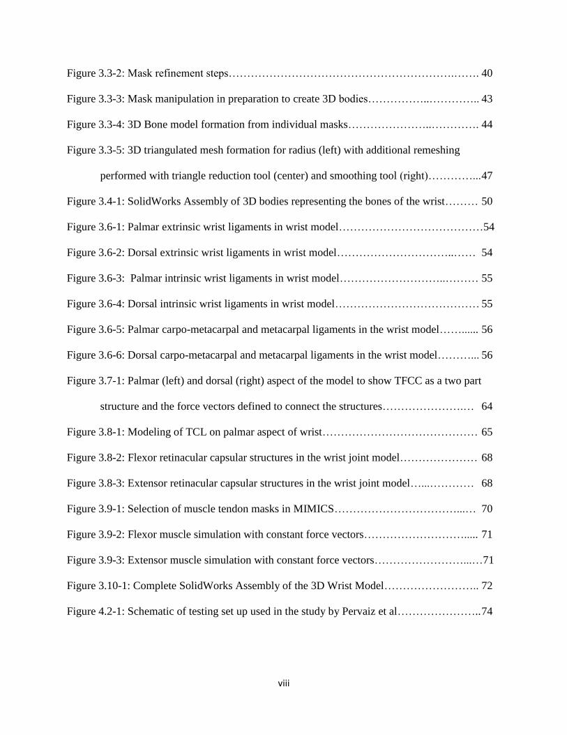
Figure 3.3-2: Mask refinement steps…………………………………………………….……. 40
Figure 3.3-3: Mask manipulation in preparation to create 3D bodies……………..………….. 43
Figure 3.3-4: 3D Bone model formation from individual masks…………………..…………. 44
Figure 3.3-5: 3D triangulated mesh formation for radius (left) with additional remeshing
performed with triangle reduction tool (center) and smoothing tool (right)…………... 47
Figure 3.4-1: SolidWorks Assembly of 3D bodies representing the bones of the wrist……… 50
Figure 3.6-1: Palmar extrinsic wrist ligaments in wrist model…………………………………54
Figure 3.6-2: Dorsal extrinsic wrist ligaments in wrist model…………………………..…… 54
Figure 3.6-3: Palmar intrinsic wrist ligaments in wrist model………………………..……… 55
Figure 3.6-4: Dorsal intrinsic wrist ligaments in wrist model………………………………… 55
Figure 3.6-5: Palmar carpo-metacarpal and metacarpal ligaments in the wrist model……...... 56
Figure 3.6-6: Dorsal carpo-metacarpal and metacarpal ligaments in the wrist model………... 56
Figure 3.7-1: Palmar (left) and dorsal (right) aspect of the model to show TFCC as a two part
structure and the force vectors defined to connect the structures………………….… 64
Figure 3.8-1: Modeling of TCL on palmar aspect of wrist…………………………………… 65
Figure 3.8-2: Flexor retinacular capsular structures in the wrist joint model………………… 68
Figure 3.8-3: Extensor retinacular capsular structures in the wrist joint model…...………… 68
Figure 3.9-1: Selection of muscle tendon masks in MIMICS……………………………...… 70
Figure 3.9-2: Flexor muscle simulation with constant force vectors………………………..... 71
Figure 3.9-3: Extensor muscle simulation with constant force vectors……………………...…71
Figure 3.10-1: Complete SolidWorks Assembly of the 3D Wrist Model…………………….. 72
Figure 4.2-1: Schematic of testing set up used in the study by Pervaiz et al………………….. 74

ix
Figure 4.2-2: Radiograph images of wrist with RSL fusion, RSL fusion and scaphoid distal pole
excision, and RSL fusion, scaphoid distal pole excision and triquetrum excision…..... 75
Figure 4.3-1: Wrist model with radius and ulna fixed and gravity defined (green arrow) for RSL
Fusion study………………………………………………………………..………….. 76
Figure 4.3-2: Simulated fusion of scaphoid and lunate to radius………………………………78
Figure 4.4-1: Projected coronal plane to measure wrist flexion/extension angles……………. 80
Figure 4.4-2: Projected sagittal plane to measure wrist radial/ulnar deviation angles……..…. 80
Figure 4.4-3: Extension angle measured between long axis of radius and third metacarpal….. 81
Figure 4.4-4: Ulnar Deviation angle measured between axis of radius and third metacarpal….81
Figure 4.5-1: Range of motion obtained during flexion in 3 studies…………………………...82
Figure 4.5-2: Range of motion obtained during extension in 3 studies………………………...82
Figure 4.5-3: Range of motion obtained during radial deviation in 3 studies……………….…83
Figure 4.5-4: Range of motion obtained during ulnar deviation in 3 studies…………………..83
Figure 4.5-5: Tension generated in Scaphocapitate ligament in Intact Wrist……………..…... 85
Figure 4.5-6: Tension generated in Scaphocapitate ligament in RSL Fusion Wrist………..…. 86
Figure 4.5-7: Comparison of tension generated in wrist ligaments during flexion……..….…..87
Figure 4.5-8: Comparison of tension generated in wrist ligaments during extension………… 87
Figure 4.5-9: Comparison of tension generated in wrist ligaments during radial deviation….. 88
Figure 4.5-10: Comparison of tension generated in wrist ligaments during ulnar deviation…. 88
Figure 5.2-1: Testing fixture to hold and test cadaveric specimens during PRC studies………90
Figure 5.3-1: Wrist model orientation and gravity direction (green arrow) for PRC experimental
studies…………………………………………………………………………...…….. 95
Figure 5.3-2: Wrist model after applying simulated PRC procedure…………………...…….. 97
x
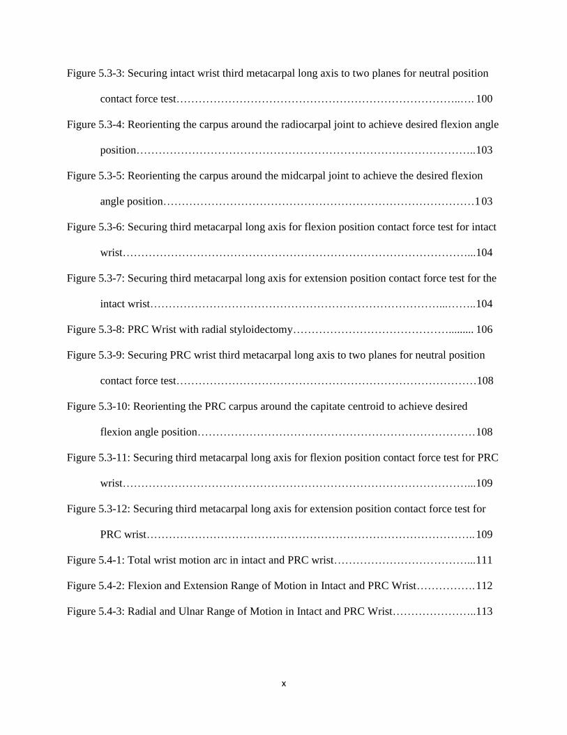
Figure 5.3-3: Securing intact wrist third metacarpal long axis to two planes for neutral position
contact force test…………………………………………………………………..…. 100
Figure 5.3-4: Reorienting the carpus around the radiocarpal joint to achieve desired flexion angle
position……………………………………………………………………………….. 103
Figure 5.3-5: Reorienting the carpus around the midcarpal joint to achieve the desired flexion
angle position…………………………………………………………………………1 03
Figure 5.3-6: Securing third metacarpal long axis for flexion position contact force test for intact
wrist…………………………………………………………………………………...104
Figure 5.3-7: Securing third metacarpal long axis for extension position contact force test for the
intact wrist……………………………………………………………………...…….. 104
Figure 5.3-8: PRC Wrist with radial styloidectomy……………………………………......... 106
Figure 5.3-9: Securing PRC wrist third metacarpal long axis to two planes for neutral position
contact force test………………………………………………………………………108
Figure 5.3-10: Reorienting the PRC carpus around the capitate centroid to achieve desired
flexion angle position………………………………………………………………… 108
Figure 5.3-11: Securing third metacarpal long axis for flexion position contact force test for PRC
wrist…………………………………………………………………………………...109
Figure 5.3-12: Securing third metacarpal long axis for extension position contact force test for
PRC wrist…………………………………………………………………………….. 109
Figure 5.4-1: Total wrist motion arc in intact and PRC wrist………………………………... 111
Figure 5.4-2: Flexion and Extension Range of Motion in Intact and PRC Wrist……………. 112
Figure 5.4-3: Radial and Ulnar Range of Motion in Intact and PRC Wrist…………………..113
xi
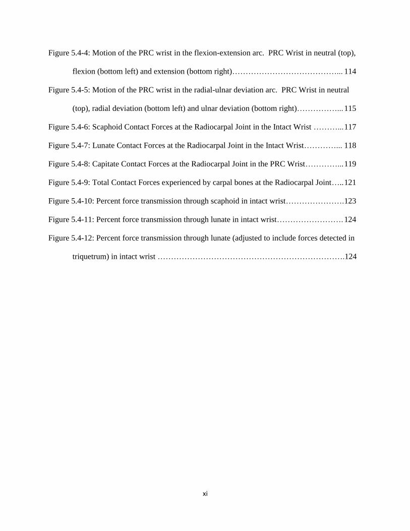
Figure 5.4-4: Motion of the PRC wrist in the flexion-extension arc. PRC Wrist in neutral (top),
flexion (bottom left) and extension (bottom right)…………………………………... 114
Figure 5.4-5: Motion of the PRC wrist in the radial-ulnar deviation arc. PRC Wrist in neutral
(top), radial deviation (bottom left) and ulnar deviation (bottom right)……………... 115
Figure 5.4-6: Scaphoid Contact Forces at the Radiocarpal Joint in the Intact Wrist ………... 117
Figure 5.4-7: Lunate Contact Forces at the Radiocarpal Joint in the Intact Wrist…………... 118
Figure 5.4-8: Capitate Contact Forces at the Radiocarpal Joint in the PRC Wrist…………... 119
Figure 5.4-9: Total Contact Forces experienced by carpal bones at the Radiocarpal Joint….. 121
Figure 5.4-10: Percent force transmission through scaphoid in intact wrist…………………. 123
Figure 5.4-11: Percent force transmission through lunate in intact wrist……………………. 124
Figure 5.4-12: Percent force transmission through lunate (adjusted to include forces detected in
triquetrum) in intact wrist …………………………………………………………….124

xii
LIST OF ABBREVIATIONS
2D Two-Dimensional
3D Three-Dimensional
APL Abductor Pollicis Longus
CAD Computer-Aided Design
CH Capitohamate Interosseous Ligament
CT Capitotrapezoidal Interosseous Ligament
CT Computed Topography
DIC Dorsal Intercarpal Ligament
DICOM Digital Imaging and Communications in Medicine
DRC Dorsal Radiocarpal Ligament
ECRB Extensor Carpi Radialis Brevis
ECRL Extensor Carpi Radialis Longus
ECU Extensor Carpi Ulnaris
ER Extensor Retinaculum
FCR Flexor Carpi Radialis
FCU Flexor Carpi Ulnaris
FEA Finite Element Analysis
FR Flexor Retinaculum
HU Hounsfield Units
ISB International Society of Biomechanics
LRL Long Radiolunate Ligament

xiii
LT Lunotriquetral Interosseous Ligament
PH Pisohamate Ligament
PRC Proximal Row Carpectomy
PT Pisotriquetral Interosseous Ligament
RBM Rigid Body Modeling
RC Radiocapitate Ligament
RS Radioscaphoid Ligament
RSC Radioscaphocapitate Ligament
RSL Radioscapholunate
SC Scaphocapitate Ligament
SL Schapholunate Interosseous Ligament
SRL Short Radiolunate Ligament
STL Stereolithographic
STT Scaphotrapeziotrapezoidal Ligament
TC Triquetrocapitate Ligament
TCL Transverse Carpal Ligament
TFCC Triangular Fibrocartilage Complex
TH Triquetrohamate Ligament
TT Trapeziotrapezoidal Interosseous Ligament
UC Ulnocapitate Ligament
UL Ulnolunate Ligament
UT Ulnotriquetrum Ligament
xiv
Abstract
THE DESIGN, DEVELOPMENT AND VALIDATION OF A COMPUTATIONAL MODEL
OF THE HUMAN WRIST JOINT
By Afsarul Quddus Mir, B.S.
A Thesis submitted in partial fulfillment of the requirements for the degree of Master of Science
in Biomedical Engineering at Virginia Commonwealth University
Virginia Commonwealth University, 2013
Major Director: Jennifer S. Wayne, Ph.D.
Professor, Biomedical Engineering & Orthopaedic Surgery
Director, Orthopaedic Research Laboratory
Advancements in computational capabilities have allowed researchers to turn towards
modeling as an efficient tool to replicate and predict outcomes of complex systems.
Computational models of the musculoskeletal system have gone through various iterations with
early versions employing dramatic simplifications. In this work, a three-dimensional
computational model of the wrist joint was developed. It accurately recreated the skeletal
structures of the hand and wrist and represented the constraints imposed by soft tissue structures
like ligaments, tendons, and other surrounding tissues. It was developed to function as a tool to
xv
investigate the biomechanical contributions of structures and the kinematic response of the wrist
joint.
The model was created with the use of a commercially available computer-aided design
software employing the rigid body modeling methodology. It was validated against three
different cadaveric experimental studies which investigated changes in biomechanical response
following radioscapholunate fusion and proximal row carpectomy procedures. The kinematic
simulations performed by the model demonstrated quantitatively accurate responses for the range
of motions for both surgical procedures. It also provided some understanding to the trends in
carpal bone contact force changes observed in surgically altered specimens. The model provided
additional insight into the importance of structures like the triangular fibrocartilage and the
capsular retinacular structures, both of which are currently not very well understood. As better
understanding of components of the wrist joint is achieved, this model could function as an
important tool in preoperative planning and generating individualized treatment regiments.

1
CHAPTER 1: INTRODUCTION
1.1 OVERVIEW OF MUSCULOSKELETAL TESTING
1.1.1 Musculoskeletal Testing Methods
The musculoskeletal system is a complex system of different anatomical structures
working together to allow locomotion, support and stability of the human body. The main
structures involved are the bones, cartilage, muscles, ligaments, tendons and other soft
connective tissues. Diarthrodial joints allow for large range controlled motion and are
responsible for the body’s mobility and dexterity. Injuries and degenerative diseases to the
musculoskeletal system can have a great effect on the quality of life of an individual. Thus,
numerous studies have been conducted to understand the function of a normal, healthy joint and
the effect of injuries or diseases on its function.
Researchers employ three main methods to study and understand the function and
behavior of musculoskeletal joints. The first method is through clinical studies, which involves
patients undergoing interventions or corrective procedures to determine the ultimate effect and
benefits. This method has the advantage of testing on native living tissue, accounting for
healing, and providing the true outcome. Among disadvantages, the main issue lies in the
difficulty to determine the changes occurring in individual components of the joint.
Additionally, patient response is highly varied, there is very limited control over parameters,
tends to be very expensive, and it only allows for a very superficial understanding of the
outcome.
The second method of investigation is experimental studies. In this method, researchers
aim to replicate living tissue by testing cadaveric specimens and/or implementing mechanical

2
simulators. Testing can be conducted under controlled conditions with the application of
improvements and restrictions on the specimen to determine the outcome. This method has the
advantage of permitting control over forces, motions as well as other parameters. However, this
method has similar disadvantages as clinical studies. Not all parameters can be accurately
measured or controlled and the process tends to be quite expensive and time consuming.
Furthermore, the degradation of the tissue may lead to inaccurate results. During experimental
studies, mechanical instruments are sometimes implemented to measure parameters. Hardware
like transducers or pressure sensitive films may further disrupt the integrity and natural response
of the joint.
With the advances in computational technology in the last several decades, researchers
are employing modeling to study the complexities of human musculoskeletal joints.
Computational modeling allows for an efficient means to replicate a complex system. This can
be done by utilizing known properties of tissue, conducting tests under very controlled
parameters, accurately measuring results, and efficiently replicating tests on identically modeled
tissue. Modeling can also help identify effects resulting from changes to specific parameters or
structures. Overall, computational modeling can be a cost effective means of conducting a study
without a large sample as required for clinical trials. The main drawback lies in the formulation
of the model itself. This is highly reliant on our knowledge of native tissue behavior and the
modelers’ ability to recreate this in silico. Additionally, due to computational limitations, every
functional component of a joint may not be incorporated. Thus simplifications and assumptions
are implemented that may potentially affect accuracy.
Once computational models have been validated, these have a great potential to be used
as a tool to understand the function and components of a joint. Models can also be used to

3
understand the functional effects of pathologies and trauma and to determine the outcomes of
new surgical techniques. This tool can also potentially be used for pre-operative planning for
complex surgeries to determine the optimum procedure. As a post operatively analysis tool, it
can also help with rehabilitation for uncommon and unique surgical techniques.
1.2 COMPUTATIONAL MODELING OF MUSCULOSKELETAL SYSTEMS
1.2.1 Types of Modeling
In the study of musculoskeletal joints, computational modeling methods have generally
fallen under two categories: finite element analysis (FEA) and rigid body modeling (RBM).
Both of these techniques result in different types of information. Traditionally, FEA is
conducted to determine the stress and strain distribution of materials under static loading
conditions. On the other hand, RBM is more effective in studying dynamic multi-body systems
to determine responses due to perturbations.
1.2.2 Finite Element Analysis
FEA is an efficient numerical technique for approximating solutions to a variety of
engineering and physics problems in one, two, three or four-dimensions. It is a powerful tool to
evaluate stresses in structures with highly irregular shapes, materials and loading behavior.
Within the literature, a large number of FEA studies exist that examine the function and
pathologies in a variety of joints like the shoulder, knee, spine, wrist, foot, elbow and hip, as well
as in individual bones. Due to the nature and complexity of the wrist joint, FEA can be
challenging to conduct. However, researchers have used FEA to look at stress distribution and
4
load transmission through the normal wrist, [1–4] traumatized wrist [3], [5–9], and wrists with
corrective surgical procedures [10], [11].
During FEA modeling, a complex domain is subdivided into smaller elements. These
elements have defined physical properties and dimensions. The reaction of each individual
element to an applied load or perturbation can be used to approximate the overall behavior of the
entire domain. In orthopaedics, FEA has been used to study and understand normal bones, joints
and the effects of degeneration and trauma. It has also been used to design and enhance implants
and other medical devices. This technique has permitted researchers to determine the stress and
strain distributions, load transfers, fractures and failures from forces experienced by
musculoskeletal structures.
Even with its strengths and advantages, FEA does have limitations. This method is
highly reliant on the material properties (density, Young’s modulus, shear modulus, Poisson’s
ratio, etc) that are defined by the user. For biological tissue, such properties can be difficult to
determine and are highly variable between structures as well as regions within the same
structure. In most cases, artificial constraints must be imposed to allow the system to solve.
Additionally, this method of analysis may also take extensive time to compute due to the fine
meshes formed by replicating complex structures. Thus, FEA is not as useful of a tool to study
kinematics or dynamic function in biomechanics.
1.2.3 Rigid Body Modeling
RBM consists of representing a body as a solid, inelastic, incompressible structure. Such
an assumption can be made in cases where the material being studied has a high stiffness and
would require very high stresses to cause more than 1% total strain. [12] This method of
5
modeling is governed by the assumption that the structures are undeformable and impenetrable at
the contact interfaces and are only bound by the constraining forces or defined boundary
conditions.
In RBM modeling, the bones are modeled as solid bodies, while ligaments, tendons,
cartilage and other soft tissues are modeled as spring elements. These spring elements can be
defined as linear/nonlinear, tension/compression only, or both depending on the native tissue
characteristics or function being replicated. With these models, the kinematic response of the
joint is primarily dependent on the contact surfaces between the bodies and the restrictions
imposed by the spring elements.
Numerous studies have been conducted that apply the RBM method to musculoskeletal
joints. This method’s strength lies in determining kinematics and effects of perturbations in a
dynamic multi-body system in a time efficient manner.
One of the first weaknesses arises from the manner in which the user defines the soft
tissues represented by the spring elements. While RBM requires fewer tissue mechanical
properties, many of which can be obtained from simple mechanical testing, there is little
consensus on the measured properties within the literature. In many cases, as with the wrist,
some structures may be too small and difficult to test and determine its mechanical properties.
An additional issue with existing RBM methods is the accurate representation of the lines
of action of soft tissue structures. Muscles and tendons have traditionally been represented as
straight line force vectors between the anatomical origin and insertion point. With dynamic
joints, this may not create an accurate representation of the tissue. As the bones in the joint
move through their motion arc, the tendon may wrap around the bones and have a different
moment arm for the muscle. In most modeling methods, a straight line vector would not be able

6
to accurately replicate wrapping or the muscular moment arm. In fact, the vector would most
likely interfere and overlap the bones and be anatomically incorrect. This same effect can be
seen in larger ligaments and capsular structures, which physiologically have both a tension and
“wrapping” stabilization function on a joint. To mimic anatomically correct lines of action,
additional measures may have to be implemented. These may include defining points to redirect
lines of action or utilizing spherical/ cylindrical elements to recalculate moment arms through
joint motion. [13] The use of the latter method can be difficult, time consuming, and may not
always be effective for the purpose of a study.
For many existing musculoskeletal RBM models, complex joints have been
oversimplified and modeled as ideal mechanical joints. For example, the elbow and knee joints
have been modeled as hinges, and the shoulder has been modeled as a ball and socket joint [14]
or as a three hinge joint. [15] These types of simplifications and assumptions do not realistically
mimic true human joint function and may not lead to an effective predictive tool.
The first RBM for the musculoskeletal system was developed by Wismans et al for the
human knee joint. [16] In this model, the bony articular surfaces were assumed to be rigid and
force vectors represented the soft tissue structures. Subsequently, researchers began developing
models embracing a similar methodology. Further development of the theory led to the
capabilities such as measuring contact surface area and contact force generation. [17] These
improvements have allowed for the formation of dynamic models, which have given researchers
a tool for investigations.
For computational models to become an effective predictive tool for musculoskeletal
joints, simulations should be solved in forward dynamic manner. This should entail minimal
artificial limitations in the degrees of freedom of the joint. But primarily, kinematics and

7
function should be dictated by the contact surfaces between the bones and the soft tissue
restraints.
1.2.4 Existing Wrist Rigid Body Models
The wrist is a complex structure comprised of multiple small bones and a large network
of soft tissue structures. Due to this complexity, it has been difficult to create an effective model
for this joint. There are a plethora of different studies that have employed wrist RBMs over the
years. These were developed in an iterative manner with early studies employing very dramatic
simplifications. More effective models were developed as computational capabilities become
more sophisticated.
Early studies that have modeled the wrist were two-dimensional (2D) reductions for
simplification purposes. These studies employed a similar methodology of modeling bones as
rigid structures and soft tissues as spring elements. The first RBM modeling of the wrist was
conducted by Horii et al. [10] This study analyzed a simplified 2D articulating wrist model to
look at changes in force transmission through the carpus with different surgical procedures to
treat Kienbock’s disease. For this test, a simulated grip loading maneuver was imposed on the
carpus. This involved application of an axial load along the long axis of the metacarpal bones.
Similar studies have been conducted by Schuind et al [18] and Manal et al [19] with 2D wrist
models. In the study by Schuind et al, force and pressure transmission through normal healthy
adult wrists were examined during simulated static grip loading. In addition, to the elimination
of the third dimension, these models were further simplified by representing the trapezium and
trapezoid bones as one unit and with the exclusion of the pisiform.
8
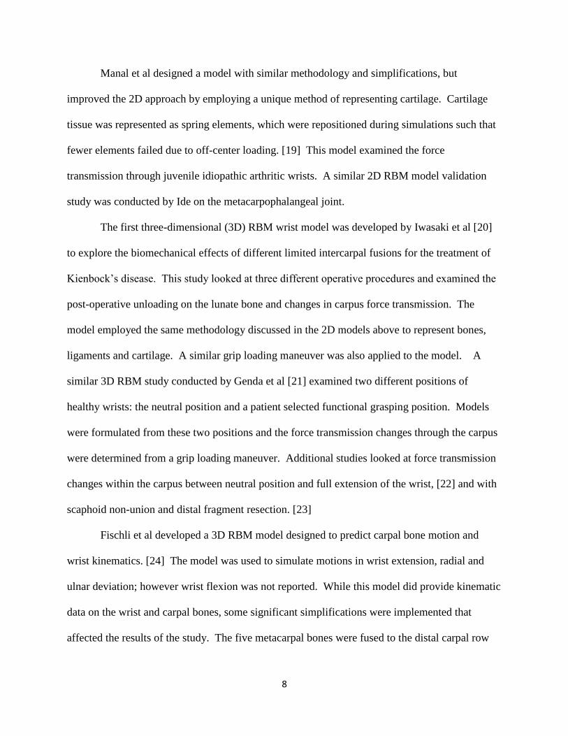
Manal et al designed a model with similar methodology and simplifications, but
improved the 2D approach by employing a unique method of representing cartilage. Cartilage
tissue was represented as spring elements, which were repositioned during simulations such that
fewer elements failed due to off-center loading. [19] This model examined the force
transmission through juvenile idiopathic arthritic wrists. A similar 2D RBM model validation
study was conducted by Ide on the metacarpophalangeal joint.
The first three-dimensional (3D) RBM wrist model was developed by Iwasaki et al [20]
to explore the biomechanical effects of different limited intercarpal fusions for the treatment of
Kienbock’s disease. This study looked at three different operative procedures and examined the
post-operative unloading on the lunate bone and changes in carpus force transmission. The
model employed the same methodology discussed in the 2D models above to represent bones,
ligaments and cartilage. A similar grip loading maneuver was also applied to the model. A
similar 3D RBM study conducted by Genda et al [21] examined two different positions of
healthy wrists: the neutral position and a patient selected functional grasping position. Models
were formulated from these two positions and the force transmission changes through the carpus
were determined from a grip loading maneuver. Additional studies looked at force transmission
changes within the carpus between neutral position and full extension of the wrist, [22] and with
scaphoid non-union and distal fragment resection. [23]
Fischli et al developed a 3D RBM model designed to predict carpal bone motion and
wrist kinematics. [24] The model was used to simulate motions in wrist extension, radial and
ulnar deviation; however wrist flexion was not reported. While this model did provide kinematic
data on the wrist and carpal bones, some significant simplifications were implemented that
affected the results of the study. The five metacarpal bones were fused to the distal carpal row

9
and the pisiform was fused to the triquetrum. Functionally, it has been shown that there is little
to no motion between the third metacarpal and the capitate, [25] and thus fusion of these two
bones may be justified. However, there is significant motion observed between the remaining
bones in the carpometacarpal joint. [26] Additionally, the pisiform has been described as a
sesamoid bone that transmits forces from the FCU to the triquetrum, hamate and the fifth
metacarpal bone. [27–29] Fusion of the piso-triquetral joint will predictably have a significant
impact in this force transmission. This study was also modeled in an inverse dynamic fashion,
such that muscular forces were prescribed to match end point positions obtained from
radiographic scans. While this may provide some information regarding individual components
in different wrist positions, this cannot be used as a predictive tool to determine joint response.
The 3D RBM developed by Majors et al [30] does not constrain the wrist’s degrees of
freedom, nor restrict the model to testing in a static or neutral position. It also does not impose
any sort of bone fusion for simplification purposes. Following the standard RBM methodology,
all the bones were modeled as rigid bodies, the ligaments were represented as tension only spring
elements and muscles as force vectors. The study examined the changes in wrist kinematics after
a carpal fusion procedure and carpal bone excision. In this case, a forward dynamic solution
method was employed.
Even though this model did not employ any of the simplifications implemented by
previous wrist models, it still had some shortcomings. The model itself did not incorporate some
essential soft tissue structures that are part of this complex joint system. The triangular
fibrocartilaginous complex (TFCC) is a structure that contributes to ulnar side stability and force
transmission. [31] The retinacular structures that encompass the entire joint also play an

10
important role of stabilization. Since these structures are important in normal wrist function,
their incorporation may be quite important in accurately replicating wrist kinematics.
11
1.3 OBJECTIVES
It is the objective of this thesis to design, develop and validate a three-dimensional
computational model of the human wrist joint. The model will allow the investigation of the
joint’s overall biomechanical function and the individual contributions of structures in the
kinematic response of the wrist. A rigid body model will be created through the use of
SolidWorks, a commercially available computer-aided design (CAD) program. Rigid body
modeling simulation will be conducted within SolidWorks Motion, a native SolidWorks add-in,
which implements the ADAMS modeling package. The model will be created by accurately
rendering the bony structures in the wrist, replicating bony contact, and applying constraints via
ligamentous and other soft tissue structures. Kinematic motion will be achieved by applying
forces to relevant muscle tendons. This model will overcome simplifications reported by
previous models where multiple bones were considered to function as one unit or were
eliminated from the design space. It will also be able to achieve motions in all three dimensions.
Additionally, the human wrist joint is comprised of a large number of soft tissue structures that
have been previously disregarded. These soft tissue structures will be further investigated and
incorporated during the development of this model. The model will be validated against the
results of two cadaveric studies looking at the effect of surgical techniques on wrist kinematics.
[32–34] This work expands on the wrist joint model developed by B. Majors and J. Wayne. [30]
Ultimately, this model is being developed in an effort to be used as a clinical and experimental
tool to predict and analyze the outcome of wrist pathology and surgery.

12
CHAPTER 2: WRIST ANATOMY
The wrist is one of the most complex joints in the human body. Traditionally, it has been
discussed as a single joint, yet in actuality it is a compound structure that consists of four
different joints. This multi-jointed structure gives the hand its high degrees of freedom, large
range of motions, decreases structural pinch experienced at extremes and its ability to form a flat
joint surface. [35] Overall, the wrist is a highly dexterous structure essential in everyday
activities and in leading a healthy and regular lifestyle.
The wrist is considered a biaxial joint with the major motions occurring in flexion and
extension around the coronal axis, and radial and ulnar deviation around the anteroposterior axis
(Figure 2-1). Some pronation and supination may also be observed at the radiocarpal joint.
However, most of the pronation and supination positions of the hand come from forearm
rotation. In some extreme cases, it has been observed that joint incongruence and ligamentous
laxity may allow up to 45o of combined passive pronation and supination at the radiocarpal and
midcarpal joints. [35] However, this motion is not usually considered to be an additional degree
of freedom for the wrist complex.

13
Figure 2-1: Anatomical regions and wrist motions around the indicated axes (palmar view
of the right wrist). [36]
14
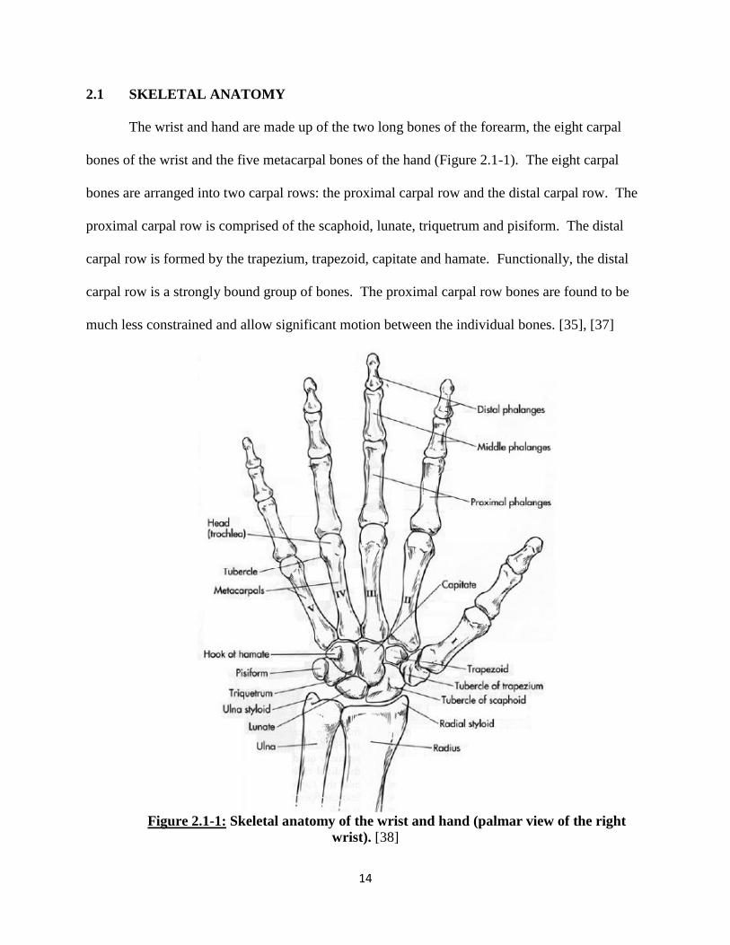
2.1 SKELETAL ANATOMY
The wrist and hand are made up of the two long bones of the forearm, the eight carpal
bones of the wrist and the five metacarpal bones of the hand (Figure 2.1-1). The eight carpal
bones are arranged into two carpal rows: the proximal carpal row and the distal carpal row. The
proximal carpal row is comprised of the scaphoid, lunate, triquetrum and pisiform. The distal
carpal row is formed by the trapezium, trapezoid, capitate and hamate. Functionally, the distal
carpal row is a strongly bound group of bones. The proximal carpal row bones are found to be
much less constrained and allow significant motion between the individual bones. [35], [37]
Figure 2.1-1: Skeletal anatomy of the wrist and hand (palmar view of the right
wrist). [38]

15
As previously mentioned, the wrist is made up of four joints: radio-ulnar joint,
radiocarpal joint, midcarpal joint, and carpometacarpal joint (Figure 2.1-2). In combination,
these four joints provide the full range of motions of this versatile structure. Starting from the
proximal end, the radioulnar joint is formed by the distal interaction between the radius and ulna.
The radiocarpal joint is formed by the articulations of the radius and ulna with the proximal
carpal row. The midcarpal joint is created between the proximal carpal row and the distal carpal
row. And most distally, the carpometacarpal joint forms from the articulations between the distal
carpal row and the five metacarpals of the hand.
Figure 2.1-2: The joints of the wrist (palmar view of the right wrist).
At the distal radioulnar joint, the ulnar head articulates with the radius at the radial ulnar
notch. The triangular fibrocartilage complex (TFCC) is a soft tissue structure that sits atop the
Distal Radioulnar Joint
Radiocarpal Joint
Mid-carpal Joint
Carpometacarpal Joint

16
ulnar head and is attached to the radius via the dorsal and palmar radioulnar ligaments. Along
with these ligaments, the TFCC is a critical structure in providing distal radioulnar joint stability.
[39], [40]
At the radiocarpal joint, the scaphoid exclusively articulates with the lateral radial facet,
the lunate primarily articulates with the medial radial facet having some interactions with the
TFCC and the triquetrum predominantly articulates with the TFCC. [35] A large portion of the
total range of motion experienced by the wrist occurs at the radiocarpal joint. This is due to the
bony articulations and the ligamentous structures that secure the scaphoid and the lunate. Due to
a larger dynamic role, the bones of the radiocarpal joint experience large forces and are more
prone to trauma and fractures.
As a part of the proximal row, the pisiform does not have any major articulating surfaces
other than the relatively flat contact face with the triquetrum. The pisiform functions entirely as
a sesamoid bone, presumably to increase the moment arm of the flexor carpi ulnaris (FCU)
tendon. [35] It is also the only carpal bone with a tendinous insertion. The pisiform is embedded
within the FCU tendon, but it also has ligamentous attachments with the triquetrum, hook of
hamate and fifth metacarpal. Through these soft tissue attachments, it transmits muscular force
from the FCU to the rest of the carpus. [28] Additionally, the pisiform acts as an attachment site
for part of the flexor retinaculum and integrates with part of the TFCC and the extensor
retinaculum. While there has been some early controversy regarding the attachment of the
extensor retinaculum to the pisiform, it is now accepted that the soft tissue structure wraps
around the medial aspect of the wrist and attaches to the ulnar styloid process, the triquetrum and
the posterior medial margin of the pisiform. [28], [41] Thus, this small bone is a soft tissue
attachment focal point on the ulnar aspect of the wrist. [28]

17
The midcarpal joint is formed by articulations of the proximal row and the distal carpal
row. The bones of the distal carpal row (the trapezium, trapezoid, capitate and hamate) are
tightly bound together through ligamentous structures. The hamate is a pyramidal shaped bone
at the medial end of the distal row. From the palmar surface arises a hook like protrusion which
acts as the medial wall of the carpal tunnel and as the attachment point for a few carpal
ligaments. The capitate is the largest carpal bone and has been described as the center of the
wrist. It articulates with three metacarpal bones and four carpal bones. Its proximal pole sits
within the curved facets formed between the scaphoid and lunate and acts as the pivot point
between the two carpal rows. The trapezoid and the trapezium line up on the lateral end of the
distal row. Since the midcarpal joint does not form a continuous articular surface, it has been
described as a functional joint rather than an anatomical joint. Additionally, the strong union
between the bones within this row results in an almost equal load distribution across the three
articulating surfaces between the joint. [35]
2.2 SOFT TISSUE ANATOMY
The kinematics and range of motion of the wrist joint complex is fully dependent on the
interactions of the respective bones and the stabilizing soft tissue structures. It is dependent on
the manner in which the ligaments secure the bones together, the motions permitted by the laxity
of the ligaments, the articulating surfaces of the bones, the stabilizing effects of the capsular
structures surrounding the joint and the constraining effects of the wrist muscles. [35]

18
2.2.1 Ligamentous Anatomy
The ligamentous structures are the most crucial elements in all joints, responsible for
maintaining articular stability of the bones as well as guiding their motions. The wrist is
composed of an elaborate network of ligaments. Many of these ligaments have been extensively
studied and reported on within the literature. In early studies, there was much confusion with the
definitions and nomenclature of the individual wrist ligaments. Currently there is a general
consensus in the literature regarding the wrist ligaments’ structure and function [29], [36], [42–
45] some differences can still be seen which arise from anatomical variations within the
population. The more numerous palmar ligaments are usually thicker and stronger. By
comparison the dorsal ligaments are fewer and usually tend to be structurally thinner. [35]
Wrist ligaments can be classified into two groups: extrinsic and intrinsic ligaments. This
classification is based upon two things: the attachment points of the ligament and the joint that
the structure crosses. Extrinsic ligaments connect carpal bones to the radius, ulna or metacarpals
while intrinsic ligaments interconnect the eight carpal bones.
Biomechanically, researchers have found that intrinsic ligaments tend to be stronger and
less stiff as compared to extrinsic ligaments. [46] This makes intrinsic ligaments less prone to
injuries. As the major stabilizers of the carpal bones, this ability better protects the integrity of
the complete carpus as a functional unit. It is theorized that one of the main reasons the intrinsic
ligaments are able to prevent injury is due to their positioning within a synovial capsule. Thus, it
seems that the extrinsic ligaments protect the intrinsic ligaments by being the primary receiver of
loads and forces that lead to injury. [46] The intrinsic ligaments tend to heal slower since they
rely upon the synovial fluid for nutrition rather than vascularized tissues as in extrinsic

19
ligaments. [35], [46] Thus, even though extrinsic ligaments are more likely to experience failure,
they tend to have a better potential for overall healing.
Extrinsic Ligaments
Extrinsic ligaments are ligaments that have an attachment point outside of the carpus and
can span across the radiocarpal joint or both the radiocarpal joint and mid carpal joint. On the
palmar aspect, the ligaments can be further subdivided into palmar radiocarpal ligaments and
ulnocarpal ligaments.
The palmar radiocarpal ligaments are composed of three distinct soft tissue structures that
attach somewhat continuously along the palmar rim of the radius. Starting radially, these bands
are the radioscaphocapitate ligament (RSC), inserting partially on the scaphoid and ending on the
front notch of the capitate, the long radiolunate (LRL) ligament and the short radiolunate (SRL)
ligament, both of which have attachment points along the lunate bone (Figure 2.2-1). A fourth
band, the radioscapholunate ligament, used to be considered part of this group of ligaments.
However, both anatomical and histological studies have shown that it is not a true ligament. This
structure has been found to contain neurovascular structures originating from the palmar carpal
branch of the radial artery and anterior interosseous artery and nerve. [47] Biomechanical
studies have also found that the radioscapholunate structure has minimal supporting
contributions to the carpal bones. [48]
The ulnocarpal ligaments are comprised of the ulnolunate (UL) ligament, the
ulnotriquetral (UT) ligament, the ulnocapitate (UC) ligament, and the ulnar collateral ligament
which includes parts of the meniscus homologue of the TFCC. On the dorsal aspect, there is
only one extrinsic ligament, the dorsal radiocarpal (DRC) ligament. This is a wide ligament
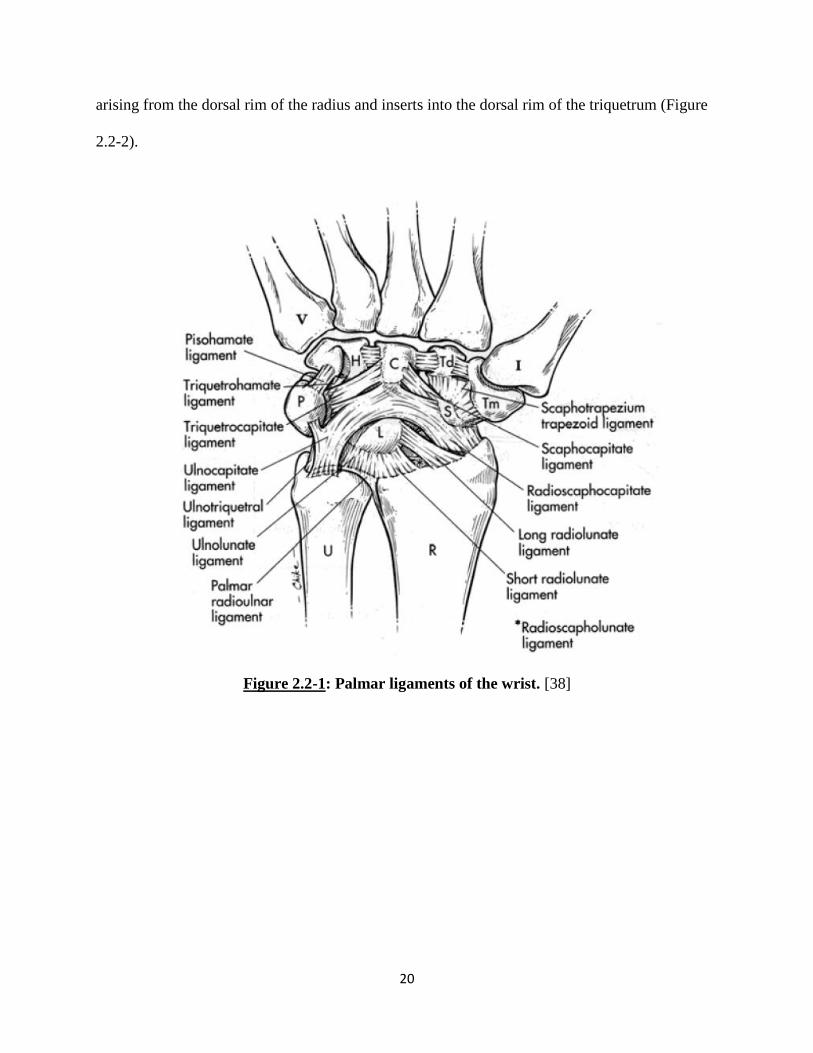
20
arising from the dorsal rim of the radius and inserts into the dorsal rim of the triquetrum (Figure
2.2-2).
Figure 2.2-1: Palmar ligaments of the wrist. [38]
21
Figure 2.2-2: Dorsal ligaments of the wrist. [38]
Intrinsic Ligaments
The intrinsic ligaments are considered to be the most important stabilizers of the carpal
bones. The interosseous ligaments do not span the mid-carpal joint, but attach to carpal bones
within each row. The most highly studied of these is the scapholunate (SL) interosseous
ligament. This ligament has been attributed to being a key factor in scaphoid stability. It is
comprised of three bands that wrap around in a C shaped manner along the articulating surfaces
of the scaphoid and lunate. The proximal row also contains the lunotriquetral (LT) ligament and
the pisotriquetral ligament (PT). In the distal row, there are three interosseous ligaments; the
trapeziotrapezoidal (TT) ligament, the capitotrapezoid (CT) ligament and the capitohamate (CH)
22
ligament (Figure 2.2-3 and Figure 2.2-4). All three of these ligaments have dorsal and palmar
regions. The interosseous ligaments of the distal row play a major role in strongly binding these
bones together, ensuring minimal motion between them and thus functionally acting as one unit.
Apart from the interosseous ligaments, the wrist joint also contains a few intrinsic
ligaments that span across the midcarpal joint. On the palmar aspect, from the radial side, there
is the scaphotrapiziotrapezoid (STT) ligament, the scaphocapitate (SC) ligament, the
triquetrocapitate (TC) ligament, the triquetrohamate (TH) ligament and the pisohamate (PH)
ligament (Figure 2.2-3 and Figure 2.2-4).
The dorsal intercarpal (DIC) ligament (Figure 2.2-2) is the only intrinsic ligament on the
dorsal aspect of the wrist. This structure originates on the triquetrum from same attachment
point as the DRC and courses horizontally to the trapezium. Some anatomical studies have also
shown some fibers of the DIC not only attach laterally to the trapezium, but also to the scaphoid
and the trapezoid and capitate. [49]

23
Figure 2.2-3: Palmar intrinsic ligaments of the wrist. [38]
Figure 2.2-4: Dorsal intrinsic ligaments of the wrist. [38]

24
2.2.2 Triangular Fibrocartilage Complex
The triangular fibrocartilage complex (TFCC) is a structure formed from the combination
of the dorsal and palmar radioulnar ligaments, ulnocarpal meniscus homologue, the triangular
fibrocartilage, the sheath of the ECU, and ulnar collateral ligament (Figure 2.2-5 – Figure 2.2-7).
[40], [50] The fibrocartilaginous articular disc of the TFCC can be considered as an extension of
the articulating surface of the distal radius. This provides a smooth semi-continuous articulating
surface for the proximal carpal row. However, the disc itself does not have a strong attachment
to the radius. It is connected directly to the radial surface via weak soft tissue fibers. The
structure’s main support arises from its dorsal and palmar integration with the radioulnar
ligaments. [50] Anatomically, the outer edges of the articular disc are thickened due to this
integration with these thick and strong ligaments. Conversely, the central region of the articular
disc tends to be shallow. [51], [52]
From the ulnar aspect, the disc is secured via two dense, fibrous connective tissue layers:
the upper and lower lamina. The upper lamina, along with the radioulnar ligaments, attach to the
ulnar head and styloid process. The lower lamina connects, through its fibers, with the ECU
sheath as well as the triquetrum, hamate and the fifth metacarpal, forming part of the ulnar
collateral ligament. The meniscus homologue is a region of irregular connective tissue that is
part of the lower lamina and traverses palmarly and ulnarly to attach to the triquetrum. Overall,
the triangular fibrocartilage complex should be considered to function as a medial extension of
the distal radial surface, providing an even and continuous articulating surface for the carpal
bones of the joint. [35], [52]
25
Figure 2.2-5: Cross-sectional view of the proximal wrist highlighting soft tissue components
of the TFCC. [53]
Figure 2.2-6: Ligaments of the forearm and wrist integrated with the TFCC. [54]

26
Figure2.2-7: Schematic of the structural components of the TFCC. [40]
MH- meniscus homologue
AD- articular disc
UCL-ulnar collateral ligament
RUL-radioulnar ligaments
ECU not shown
The TFCC is an important component for stability of the distal radioulnar joint. This
structure also acts as a supporting cushion for load transfers from the lunate and triquetrum. [40]
Due to the larger articulating surface, the radiocarpal articulating region supports about
80%while the TFCC supports about 20% of the load during compressive perturbations and
transfers the force to the forearm. [40] The complete excision or degeneration of the TFCC may
significantly reduce the forces transmitted through to the distal ulna. [40], [55] Although ulnar
variance may cause healthy individuals to have a structurally different sized TFCC, this

27
anatomical variation has still been found to lead to the same proportional (80-20) load
distribution through the radiocarpal joint.
The TFCC has a broad connection with the ECU sheath. This causes the TFCC to act as
a pulley to the extensor tendon. With complete excision of the TFCC, a 30% increase in
excursion of the tendon has been experimentally observed. [55] This increased tendon excursion
may lead to unnatural application of forces being applied to the carpus during ECU activation.
The TFCC is a complex soft tissue structure made up of multiple types of tissue. Starting
from the meniscus homologue and the fibrocartilage articulating disc, to the integrated fibers
from all the surrounding soft tissue structure, the complexes role is not very well understood.
Overall, it is thought to provide stability to the ulnar aspect of the wrist during kinematic
motions. First, the proximal region places a cradling role and provides an even and smooth
articulating surface for the lunate and triquetrum. Secondly, the more distal region is a
combination of soft tissue connections which wrap around the medial aspect of the wrist. While
the TFCC may not directly connect to the carpal bones, by wrapping around them it most likely
provides some stability in ulnar motions of the wrist.
2.2.3 Muscular Anatomy
There are six main muscles responsible for overall wrist motion. The wrist flexors are
the flexor carpi ulnaris (FCU), the flexor carpi radialis (FCR) and the abductor pollicis longus
(APL). On the wrist, the FCU inserts into the pisiform and acts to flex and adduct the wrist. The
FCR tendon’s insertion point is at the anterior base of the second metacarpal. The FCR usually
acts to flex and abduct the wrist (Figure 2.2-8). With an insertion site at the base of the first
metacarpal, the APL’s primary function is not for wrist movement, but rather to abduct the
28
thumb at the carpometacarpal joint. However, this muscle does have a secondary function that
assists with flexion and abduction of the wrist. The wrist joint extensors are the extensor carpi
radialis longus (ECRL), extensor carpi radialis brevis (ECRB), and the extensor carpi ulnaris
(ECU). The ECRL has an insertion point at the dorsal base of the second metacarpal while the
ECRB inserts at the base of the third metacarpal. These two muscles act to extend and abduct
the wrist. Conversely, the ECU inserts at the dorsal base of the fifth metacarpal and tends to
extend and adduct the wrist (Figure 2.2-9).
Figure 2.2-8: Flexor Muscles of the wrist joint. [56]

29
Figure 2.2-9: Extensor Muscles (highlighted green) of the wrist joint. [56]
30
2.2.4 Retinacular Anatomy
The wrist has a complex retinacular system which assists in maintaining normal
relationships for all the tendons that cross the wrist joint. This system acts as pulleys to redirect
the line of action of each tendon through the joint’s range of motions. The retinacular system is
a fibrous connective supporting system with three main functions; maintain mobile components
in their defined compartment, protect and retain the elements it surrounds, and to redirect the
tendinous muscular forces to maintain normal lines of action. [57], [58]
Anatomical studies have shown that the hand’s retinacular system is essentially a distal
extension of the antebrachial fascia of the arm. This fibrous structure courses distally up to the
base of the metacarpals where it thins out and blends in with the fibers of the palmar
aponeurosis. Based on the aspect of the hand, the retinacular system can be divided into two
parts: the flexor retinaculum (FR) and the extensor retinaculum (ER).
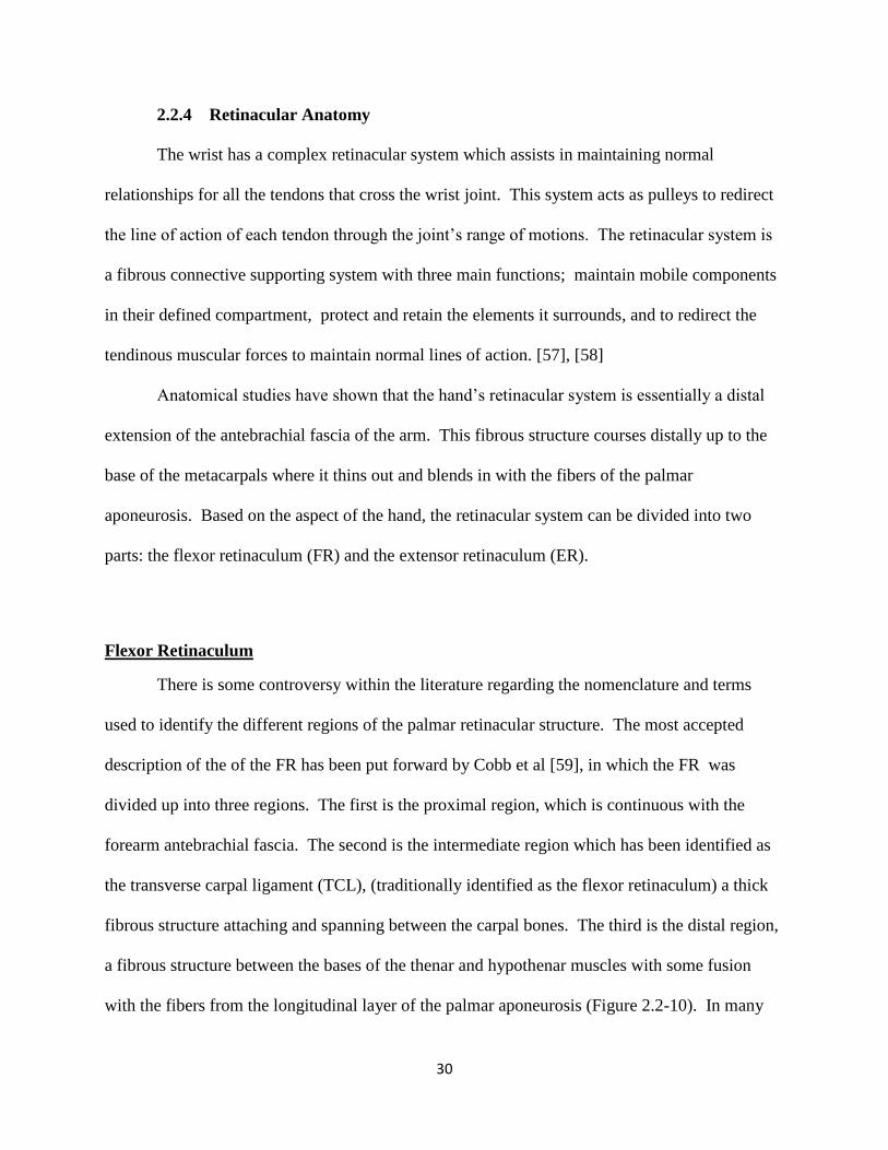
Flexor Retinaculum
There is some controversy within the literature regarding the nomenclature and terms
used to identify the different regions of the palmar retinacular structure. The most accepted
description of the of the FR has been put forward by Cobb et al [59], in which the FR was
divided up into three regions. The first is the proximal region, which is continuous with the
forearm antebrachial fascia. The second is the intermediate region which has been identified as
the transverse carpal ligament (TCL), (traditionally identified as the flexor retinaculum) a thick
fibrous structure attaching and spanning between the carpal bones. The third is the distal region,
a fibrous structure between the bases of the thenar and hypothenar muscles with some fusion
with the fibers from the longitudinal layer of the palmar aponeurosis (Figure 2.2-10). In many
31
existing anatomical texts, the terms flexor retinaculum and transverse carpal ligament are used
synonymously to describe the same structure, while others use the terms to describe separate
structures.
On the palmar aspect of the forearm, the deep layer of the antebrachial fascia thickens
and forms the proximal region of the flexor retinaculum at the radioulnar joint. This band of
tissue spans across the radius to the ulna. This thick layer of tissue is formed from two layers of
fibrous tissue which become re-apposed as they attach at the medial and lateral borders of the
radius and ulna. [59] At the proximal and mid carpal row, the fibers of the proximal part of the
TCL attach laterally to the scaphoid tuberosity and medially to the pisiform. The TCL continues
to extend distally and at the distal carpal row the structure connects medially to the hook of
hamate and laterally to the ridge of the trapezium.[57] This structure also forms the closure of
the carpal tunnel of the wrist. The carpal tunnel is a fibrous compartment through which all the
palmar tendons and some nerves travel through to the distal hand. On the distal end of the FR
structure, the FR extends up to the base of the third metacarpal. At this point the distal portion
forms the origin of the thenar and hypothenar muscles. [59] In this region, the fibers from the
palmar fascia overlap and fuse with the distal region of the FR. [57], [59]
32
Figure 2.2-10: Drawing demonstrating the three portions of the flexor retinaculum. [59]
1- Proximal portion if the FR formed from the antebrachial fascia (F).
2- Medial portion of FR, also referred to as transverse carpal ligament.
3- Distal portion of FR, aponeurosis between thenar (A) and hypothenar
muscles (B).
Extensor Retinaculum
The ER is a thick fibrous structure located on the dorsal radial and ulnar aspects of the
wrist joint (Figure 2.2-11). The ER is also formed from the distal extension of the deep forearm
antebrachial fascia. This structure is formed from two layers: the supratendinous and
infratendinous layers. [31], [60] The structures of the ER form six major compartments
containing the different dorsal tendons crossing the wrist joint (Figure2.2-12). The

33
supratendinous layer is the major layer of the structure, forming the thickest part of the ER.
Laterally, it inserts into the radius and forms the lateral septum of the first compartment. The
layer then runs slightly obliquely and attaches to the ulnar side of the triquetrum and pisiform.
The fibers also blend in with the fibers of the FCU tendon and other soft tissues at the distal end
of the TFCC structure. The infratendionus retinaculum is a narrower and shorter sheet of parallel
fibers as compared to the supratendious retinaculum. Overall, the lateral end of the ER attaches
to the distal part of the anterior border of the radius. While the medial end of the ER attaches to
the styloid process of the ulna, the pisiform and the medial border of the triquetrum. [41]
Figure 2.2-11: Dorsal aspect of hand showing extensor retinaculum (top) and Cross-
sectional view of extensor retinaculum compartments (bottom). [56]

34
Figure 2.2-12: Cross-sectional view of the distal radioulnar joint and the
compartments of the extensor retinaculum. [56]
As with the TFCC, the stabilizing role that the capsular retinacular structures play upon
the wrist is not well understood. While there are some experimental studies that looked at the
biomechanical effects of these tissue structures, the literature does not provide a complete
understanding. Studies have demonstrated decreased carpal arch stiffness [61] and increased
carpal arch length [62] with sectioning of the TCL for carpal tunnel release. Additionally,
significant bowstringing and tendon excursions to non-anatomically correct lines of action were
also observed following sectioning of the FR [62] and the ER [31]. While these studies do not
directly indicate any effect the retinaculum might have in carpal kinematics, it does indicate that
an overall stabilizing role is performed with all the surrounding tissue. By wrapping around all
the tendons, soft tissue structures and the deeper skeletal structures, the reticulum should
compact and secure all the tissues together. Its stabilizing role may be further enhanced in a
deficient wrist that has undergone trauma or surgery. In this deficient state, the primary
stabilizers may not be able to be as effective as they are designed to be and so these capsular
structures may in fact passively stabilize the weakened joint.
35
CHAPTER 3: THREE-DIMENSIONAL WRIST MODEL
FORMULATION
3.1 OVERVIEW
The aim of this study was to develop a high resolution, physiologically accurate
computational model of the human wrist joint and to study the biomechanical function of the
joint using the rigid body modeling (RBM) technique. RBM involves studying the interactions
between a system of solid bodies that are supported or restricted based on defined properties or
boundary conditions. For the wrist, this involves accurately representing the fifteen bones and
their articulating surfaces and recreating the limiting factors enforced by the ligaments and other
supporting soft tissues. In this study, high resolution computer tomography (CT) scans of a
human upper extremity were used to create a three-dimensional (3D) representation of all the
relevant bones and soft tissue structures. Once an accurately represented model of the wrist was
formulated, motion studies were conducted by replicating wrist muscle action using a
commercially available computer aided design (CAD) program and its native kinematics study
tool.
3.2 COMPUTED TOPOGRAPHY OF THE WRIST
The 3D anatomy of the wrist model was obtained from a high resolution CT scan of a
fresh frozen left upper extremity of a 52 year old male donor (Figure 3.2-1). The specimen was
inspected for any obvious pathology, deformities and proper biomechanical range of motion. No
obvious abnormalities were identified. The wrist was then scanned at high resolution with a
36
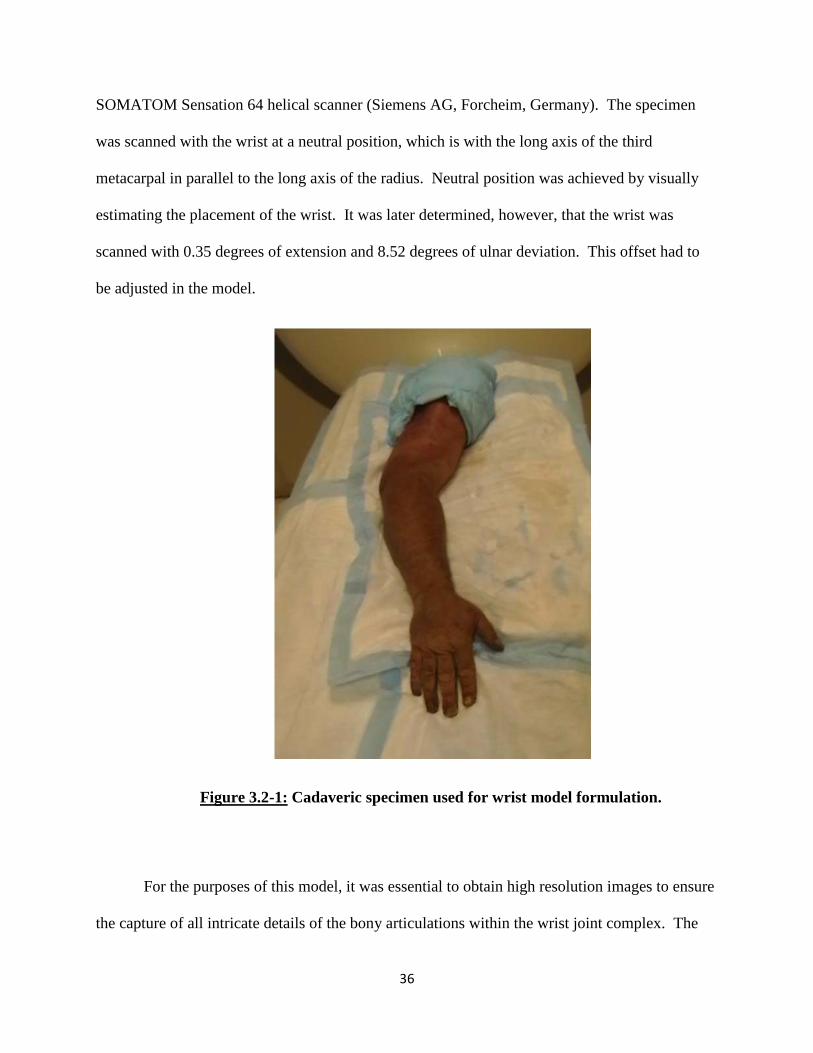
SOMATOM Sensation 64 helical scanner (Siemens AG, Forcheim, Germany). The specimen
was scanned with the wrist at a neutral position, which is with the long axis of the third
metacarpal in parallel to the long axis of the radius. Neutral position was achieved by visually
estimating the placement of the wrist. It was later determined, however, that the wrist was
scanned with 0.35 degrees of extension and 8.52 degrees of ulnar deviation. This offset had to
be adjusted in the model.
Figure 3.2-1: Cadaveric specimen used for wrist model formulation.
For the purposes of this model, it was essential to obtain high resolution images to ensure
the capture of all intricate details of the bony articulations within the wrist joint complex. The

37
scan resolution was 512 x 512 pixels with each pixel containing twelve bits of data. Scan slices
were separated by 0.4mm increments for a total 2283 two-dimensional (2D) slice images.
3.3 THREE-DIMENSIONAL BODY CREATION
3.3.1 Mask Creation
Once the high resolution CT scanned images were obtained, they were imported into the
commercially available MIMICS (Materialise’s Interactive Medical Imaging Control System,
Version 13, Materialise, Ann Arbor, MI) software for processing. MIMICS is a specially
developed software that is designed to process a number of different types of medical images and
can be used in a wide range of engineering applications. In this study, MIMICS was used to take
the 2D images from the CT scans and convert them into 3D structures to replicate the bony
anatomy of the human wrist.
The 2283 2D CT images were sequentially imported into MIMICS and were arranged
into arrays of DICOM (Digital Imaging and Communications in Medicine) images. DICOM
images are a standard format for using, storing and transmitting medical images. Within
MIMICS, this array or stack of images was then processed to form a 3D representation of the
arm. The array was formed by voxels, or volumetric pixels, whose top and bottom faces were
formed by pixels from two adjacent slices. Side faces of the voxels were dictated by the slice
thickness. Since the length of a pixel is not equal to the distance between the slices, the model
was comprised of rectangular voxels.
The entire stack of images was then processed to efficiently capture the bony structures
within the specimen. This was done by using a global thresholding tool, which can analyze each

38
pixel on a slice of the scan and designate it an active (bright) or inactive (dark) status. The tool
measures the Hounsfield units (HU), which is a scale that describes the radiodensity of a
structure. Each analyzed pixel was assigned an active or inactive state based on the HU range
desired by the user. In MIMICS, a standard threshold range for bone is defined to be between
226 to 1703 HU. When this range was used within the scan, it was found that some cortical bone
and a large part of trabecular bone remained unselected (Figure 3.1-1). This was most likely due
to the low linear attenuation coefficient of trabecular bone and the low density of cortical bone.
Thus, the threshold value was adjusted to allow a complete global capture of bony tissue. After a
number of trials, it was determined that the optimal range to capture the maximum amount of
bony tissue, while selecting a minimal amount of soft tissue, was 180 to 1703 HU. This range
was then used to form the global “mask” of the bony structures of the upper extremity.
Figure 3.3-1: Thresholding tool used to select osseous structures with standard range (left)
and redefined threshold range (right).
Continuous surface Surface discontinuity

39
3.3.2 Mask Refinement
Once a global mask was obtained, it was further refined to eliminate any soft tissue or
noise that may have been selected, as well as carefully define all the articulating surfaces
between adjacent bones. MIMICS has a number of different editing tools that allow for global
and fine changes to individual masks. The two tools used for quick mass editing were the
cropping tool and the multiple slice edit tool. The cropping tool was used to select a region of
interest within the scan. The multiple slice edit tool allowed for changes from one 2D slice
image to be copied onto adjacent slices and thus enabled quick changes to be applied to the
mask. The initial global mask obtained was of the full upper extremity. With the help of these
two tools, the mask was edited and reduced to only incorporate the distal half of the forearm and
the complete hand. In addition, any remaining noise, such as activated pixels from the scanned
portion of the CT table, was also eliminated. This resulted in a complete active mask made up of
a total of 754 images instead of the original 2283 images. This not only vastly reduced the file
size but also made the images computationally less cumbersome.
40
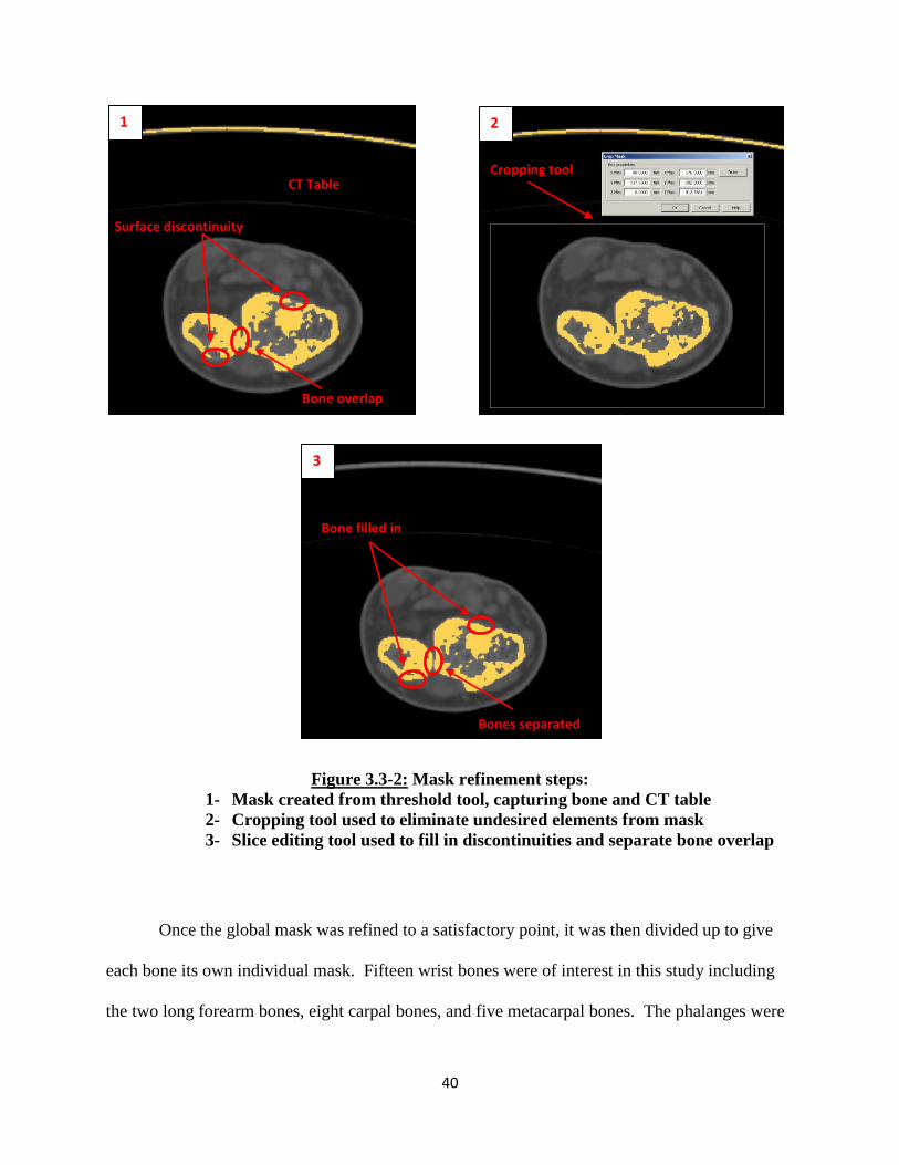
Figure 3.3-2: Mask refinement steps:
1- Mask created from threshold tool, capturing bone and CT table
2- Cropping tool used to eliminate undesired elements from mask
3- Slice editing tool used to fill in discontinuities and separate bone overlap
Once the global mask was refined to a satisfactory point, it was then divided up to give
each bone its own individual mask. Fifteen wrist bones were of interest in this study including
the two long forearm bones, eight carpal bones, and five metacarpal bones. The phalanges were
1 2
3
CT Table Cropping tool
Bone filled in
Bones separated
Surface discontinuity
Bone overlap
41
also extracted from this mask; however, the phalanges of the fingers and thumb were represented
as one mask within the design space.
For the extraction of each bone into its own mask, the group editing tools previously
described were used. Additionally, MIMICS has a number of Boolean Operation tools which
allowed for quick mask manipulations. These operation tools prevent the need to repeat the
same mask editing steps in different masks. The two main Boolean operation tools used for this
study were those that allowed for a mask to be added or subtracted from another. These tools
were utilized to quickly remove individual bone masks from the global mask, thus allowing for
faster acquisition of individual masks. During the creation of each individual bone mask, an
additional tool was used to make very fine adjustments. Within the original unedited mask of the
proximal arm, it was found that most of the articulating surfaces would not be rendered as
smooth surfaces. Furthermore, in many cases there were mask overlaps observed between
bones. This was especially seen in the cases of the small carpal bones which also had very small
joint space. The joint space between these bones was not distinct enough in the scans and so had
to be individually defined and separated. In other regions, surfaces were found to have jagged
edges due to thinning or high porosity of the bone. These discontinuities may have also been
caused by error in the designated thresholding range. Corrections to these misrepresentations
were achieved by editing each individual slice of the mask and appropriately selecting or
deselecting pixels using the slice editing tool. This was done to ensure capture of a smooth,
continuous articulating surface. This step also allowed manual compensation for any deficiency
or irregularities that existed within the wrist bones. As previously mentioned, accurately
selecting and capturing the outer cortical layer was critical. If a region inside the outer layer was
not selected, it was filled with the help of an additional tool described later.

42
MIMICS has the capability to analyze individual slices and masks to create various
geometrical references such as fitted lines or points that are based on selected regions. The
polylines function was used to create individual closed loops around each active selection on
individual slices. Since it was ensured that each mask had at least an outermost selected surface
layer of the bone, a polyline could be formed to encompass the entire bony region on that slice.
This also allowed for the identification and correction of discrepancies that showed
discontinuities, cavitations or sharp edges. Once a satisfactory polyline was obtained for all the
slices, the exterior most polyline of each slice was used to fill in any voids or inactive pixels.
These inactive pixels were usually due to the porous trabecular bone or medullar space of the
long bones. Because the presence of hollow regions is not conducive to the RBM method, it was
ensured that the entire bone was selected (Figure 3.3-3).

43
Figure 3.3-3: Mask manipulation in preparation to create 3D bodies.
1- Refined mask with separated bones and continuous outer surface
2- Polylines created to encapsulate outer boundary of bone
3- Cavity Fill function used to fill all voids in each mask
Once accurate masks of the wrist bones were developed, 3D bodies were formed from
each mask (Figure 3.3-4). This was done in MIMICS by creating a linear interpolation between
the boundaries of each active section on adjacent slices. Once formed, each bone was visually
inspected and compared to anatomical texts for accuracy and to ensure all major landmarks had
been captured. A final check confirmed that each body contained no extraneous noise and each
mask contained only one body.
1 2
3

44
Polylines calculated from mask 3D Body formed from interpolation of polylines
Figure 3.3-4: 3D Bone model formation from individual masks.
3.3.3 3D Mesh Creation and Remeshing
Once a 3D body was created, its surface was represented as a network of triangulated
surfaces, which is referred to as a 3D mesh. This triangulated 3D mesh forms the exterior
surface of the bone, representing the shape and curvature as defined by the mask. However, the
body may still contain significantly rough edges since features can be harder to identify while
working in the 2D aspect. To allow for 3D body refinement, MIMICS has a number of tools
which allow for the manipulation and modification of the 3D mesh. When a 3D body is first
formed, the surface mesh can contain over 100,000 triangles depending on the size of the bone.
Any commercially available CAD software would have a very difficult time in importing or
using such a large complex file for its calculations. In fact, if such a large file was used for
simulations, it would take an inordinate amount of time to converge to a final solution. In many
45
cases, the computational power may not be sufficient for solving and thus lead to failure.
Additionally, the presence of sharp discontinuities within a body can also result in rapid changes
during motion studies thereby producing inaccurate results or convergence failure. Thus, it was
very important to utilize these remeshing tools to reduce the number of triangles and create a
simplified, smooth surface that accurately represented bony contours.
The representative triangles of the 3D surface mesh were formed in a variety of different
sizes, angles and dimensions. The overall position of each triangle was defined by the twelve
Cartesian coordinates, three for each vertex, and three directional unit vectors. The triangle
reduction and smoothing tools were used to refine the 3D bones. These tools allowed for the
reduction of the 3D mesh triangles based on defined parameters. This remeshing led to the 3D
mesh containing a smaller number of triangles, thereby making the model more computationally
manageable. Ideally, a mesh formed by identical equilateral triangles is desirable as it leads to a
more consistent regular mesh and allows for efficient solving of computer simulations.
Triangle reduction focuses on two factors to carry out its operation (Figure 3.3-5). First,
it utilizes an algorithm to remove all highly acute and obtuse triangles from the mesh. This tool
gives each triangle a dimensionless value between 0 and 1 where equilateral triangles are rated as
1 and highly acute or obtuse angled triangles are valued closer to 0. A threshold value is then
designated by the user such that all triangles outside the threshold are eliminated while triangles
within it are preserved. The eliminated triangles are then replaced with triangles having
dimensions within the threshold. These new dimensions are driven by the dimensions and
positions of the surrounding triangles. While this step alone does not significantly reduce the
number of triangles in the mesh, it greatly improves the quality of the mesh to be formed by
incorporating facets within a uniform range.

46
The second step in triangle reduction involves the evaluation of mesh triangle edge
angles. In this case, the tool measures the angle between two facets and combines them based on
a defined threshold value. If two facets have a very small edge angle, they are considered as one
facet. Any corresponding triangles that have angles greater than the threshold are considered
two unique facets and the original orientation is maintained. The threshold angle defines the
minimum angle needed between two facets to preserve or accurately represent the surface
geometry of the body. For the purposes of this study, the threshold value for the first step was
set at 0.3 and the threshold for the edge angle was set at 15 degrees. These values were obtained
after a number of trials determined the best outcome in reducing the triangular mesh while still
preserving the total 3D volume of the body.
The next tool used during the remeshing process was the smoothing operation.
Smoothing allows for the removal of any small cavitations, spikes or discontinuities that may
still exist on the represented bone surface. The operation examines the vertices of each triangle
and the corresponding neighboring triangles that share the common vertex. In this study, the
smoothing analysis led to a weighted value being assigned based on the Smoothing Factor ratio.
During this manipulation, each vertex of all the triangles was no longer fixed and was reoriented
within the coordinate system based on the assigned weighted value. If the ratio was low, then the
initial position of the vertex was predominantly responsible for the new position in space.
However, if the ratio was high, then the new position of the vertex was driven by the position
and coordinates of the vertices of all the adjacent triangles. This operation resulted in the
vertices being redefined to a new position based on the coordinates of vertices common to
multiple triangles. While this tool was very effective in quickly removing discontinuities and

47
cavitations, care had to be taken to ensure that essential landmarks were not inadvertently
removed.
For both of these operations, multiple iterations had to be performed to result in a
satisfactory outcome. The number of iterations also depended on the bone itself with larger
bones requiring a greater number of iterations. For the long bones like the radius and ulna, a
maximum number of fifteen iterations were performed. For the smaller carpal bones, fewer
iterations were sufficient to obtain a final acceptable structure.
Figure 3.3-5: 3D triangulated mesh formation for radius (left) with additional remeshing
performed with triangle reduction tool (center) and smoothing tool (right).
Triangle reduction Smoothing

48
Once remeshing was complete, a final visual inspection of the bodies was completed. In
some cases, individual points and triangles were still found that had not been corrected by the
global smoothing and triangle reduction operations. A few very sharp points or cavitations were
easily identified in all the bone structures. In these cases, the individual triangles in the region
were manually manipulated to correct the anomaly. Individual triangles were deleted and
redrawn by moving, adding or deleting nodes. Again, very precise care was taken to ensure that
an accurate, continuous smooth surface represented the bone structure.
3.3.4 STL Files and SolidWorks
Once the remeshing operation was complete, a final high quality mesh of triangular facets
was obtained that accurately represented the shape and major landmarks of each individual bone.
Each body was then exported from MIMICS as a stereolithographic (STL) file. STL is a file
format widely used in rapid prototyping and CAD programs and is supported in most 3D
modeling software packages. STL files only describe the 3D surface geometry of an object
without any representation of color, texture or other parameters or attributes. Individual STL
files for each bone were imported into SolidWorks and saved separately as part files. During this
importation into SolidWorks, each vertex and triangular facet were recreated to rebuild an
identical body as was formed within MIMICS.
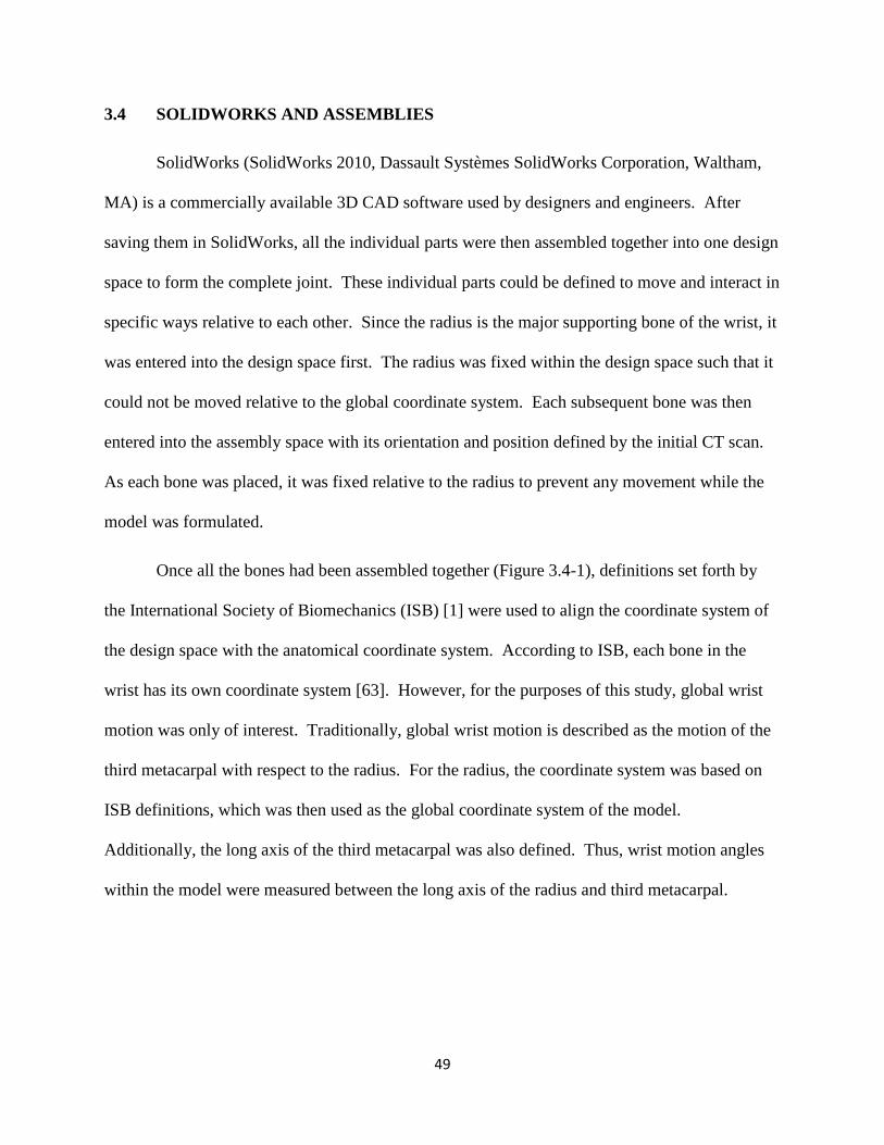
49
3.4 SOLIDWORKS AND ASSEMBLIES
SolidWorks (SolidWorks 2010, Dassault Systèmes SolidWorks Corporation, Waltham,
MA) is a commercially available 3D CAD software used by designers and engineers. After
saving them in SolidWorks, all the individual parts were then assembled together into one design
space to form the complete joint. These individual parts could be defined to move and interact in
specific ways relative to each other. Since the radius is the major supporting bone of the wrist, it
was entered into the design space first. The radius was fixed within the design space such that it
could not be moved relative to the global coordinate system. Each subsequent bone was then
entered into the assembly space with its orientation and position defined by the initial CT scan.
As each bone was placed, it was fixed relative to the radius to prevent any movement while the
model was formulated.
Once all the bones had been assembled together (Figure 3.4-1), definitions set forth by
the International Society of Biomechanics (ISB) [1] were used to align the coordinate system of
the design space with the anatomical coordinate system. According to ISB, each bone in the
wrist has its own coordinate system [63]. However, for the purposes of this study, global wrist
motion was only of interest. Traditionally, global wrist motion is described as the motion of the
third metacarpal with respect to the radius. For the radius, the coordinate system was based on
ISB definitions, which was then used as the global coordinate system of the model.
Additionally, the long axis of the third metacarpal was also defined. Thus, wrist motion angles
within the model were measured between the long axis of the radius and third metacarpal.
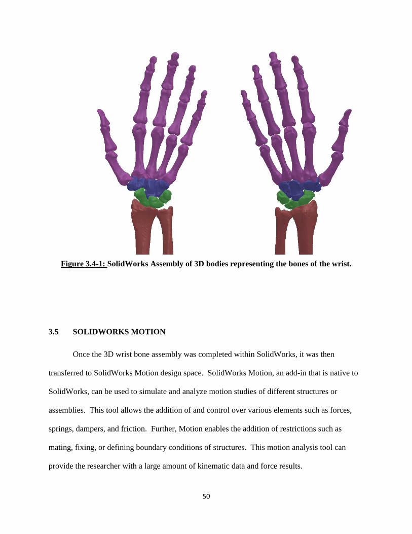
50
Figure 3.4-1: SolidWorks Assembly of 3D bodies representing the bones of the wrist.
3.5 SOLIDWORKS MOTION
Once the 3D wrist bone assembly was completed within SolidWorks, it was then
transferred to SolidWorks Motion design space. SolidWorks Motion, an add-in that is native to
SolidWorks, can be used to simulate and analyze motion studies of different structures or
assemblies. This tool allows the addition of and control over various elements such as forces,
springs, dampers, and friction. Further, Motion enables the addition of restrictions such as
mating, fixing, or defining boundary conditions of structures. This motion analysis tool can
provide the researcher with a large amount of kinematic data and force results.

51
In SolidWorks Motion, all the soft tissue structures were represented and additional
restrictions and boundary conditions were incorporated. However, first the motion analysis
study properties had to be defined. The motion study rate was set at 50 frames per second. A
high frame rate was selected to allow enough calculation points to accurately converge to a
solution. However, if too high of a frame rate was used, it could also lead to very long
computational times. Next, the geometric accuracy and 3D contact resolution of the study was
set to the maximum range. Since motion analysis is primarily dependent on the contact reactions
between the bone articulations, it was imperative to maintain high accuracy of the surfaces
during a calculation.
SolidWorks Motion computationally solves studies by iteratively solving the equations of
motions. It also considers additional user-defined forces and restrictions on the system. These
equations are solved for every time step to approach the final solution for the overall system.
For this study, the bones were defined as rigid solid bodies. To achieve this, SolidWorks
has a unique modeling method. To resolve solid body contact, the 3D contact feature first
calculates the amount of overlap that may exist between bodies during each time step. If some
overlap is detected between two or more bodies, it applies a force to the centroid of the elements
in the opposite direction of the overlapping body. This force is proportional to the amount of
volumetric overlap occurring between the bodies and the defined stiffness of the material. For
this study, stiffness was defined as 10,000 N/mm with a penetration depth of 0.001 mm and a
damping coefficient of 50 N/mm-s. These values were determined to be the optimal values to
limit the amount the overlap, while replicating the amount of repelling force experienced when
solid bodies experience contact.

52
3.6 LIGAMENT STRUCTURES
Once the bony tissues of the wrist were defined, the soft tissue structures were then
represented within the model. As done in most RBM studies, the wrist ligaments were modeled
in SolidWorks as tension only spring elements with no resistance to compression. They were
defined as straight line elements spanning the ligament attachment sites with properties
determined from experimental studies published in the literature.
3.6.1 Origins and Insertions
Recreating the wrist ligaments as elements in SolidWorks Motion involved first
identifying all the origins and insertions of each ligament. Literature and anatomical texts [29],
[36], [43], [56], [64–69] were used to identify these attachment sites. Ligament attachment
points were found in relation to various landmarks or reference points on the individual bones.
Within the literature, there is a large variation in descriptions of the wrist’s ligamentous anatomy.
This variation is primarily due to the number of ligaments in the wrist, their relatively small size,
anatomic variability among individuals, as well as the complexity of the overall system. Chapter
2 of this text discusses in depth the ligaments and structures that have been implemented in this
model of the wrist.
Each ligament was modeled as a straight line spring element that only resisted tension.
Since ligaments can be wide structures spanning attachment sites, each was modeled using at
least two linear spring elements. In some of the larger and wider ligaments, three elements were
used. The two elements were usually placed towards the outer margins of the ligament. In
representing the interosseous ligaments, two or three different bands were used, each represented
by two separate elements. Modeling the wrist in such a manner allowed sufficient replication of
the multi-directional constraining effects of an actual ligament.
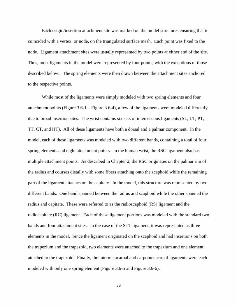
53
Each origin/insertion attachment site was marked on the model structures ensuring that it
coincided with a vertex, or node, on the triangulated surface mesh. Each point was fixed to the
node. Ligament attachment sites were usually represented by two points at either end of the site.
Thus, most ligaments in the model were represented by four points, with the exceptions of those
described below. The spring elements were then drawn between the attachment sites anchored
to the respective points.
While most of the ligaments were simply modeled with two spring elements and four
attachment points (Figure 3.6-1 – Figure 3.6-4), a few of the ligaments were modeled differently
due to broad insertion sites. The wrist contains six sets of interosseous ligaments (SL, LT, PT,
TT, CT, and HT). All of these ligaments have both a dorsal and a palmar component. In the
model, each of these ligaments was modeled with two different bands, containing a total of four
spring elements and eight attachment points. In the human wrist, the RSC ligament also has
multiple attachment points. As described in Chapter 2, the RSC originates on the palmar rim of
the radius and courses distally with some fibers attaching onto the scaphoid while the remaining
part of the ligament attaches on the capitate. In the model, this structure was represented by two
different bands. One band spanned between the radius and scaphoid while the other spanned the
radius and capitate. These were referred to as the radioscaphoid (RS) ligament and the
radiocapitate (RC) ligament. Each of these ligament portions was modeled with the standard two
bands and four attachment sites. In the case of the STT ligament, it was represented as three
elements in the model. Since the ligament originated on the scaphoid and had insertions on both
the trapezium and the trapezoid, two elements were attached to the trapezium and one element
attached to the trapezoid. Finally, the intermetacarpal and carpometacarpal ligaments were each
modeled with only one spring element (Figure 3.6-5 and Figure 3.6-6).
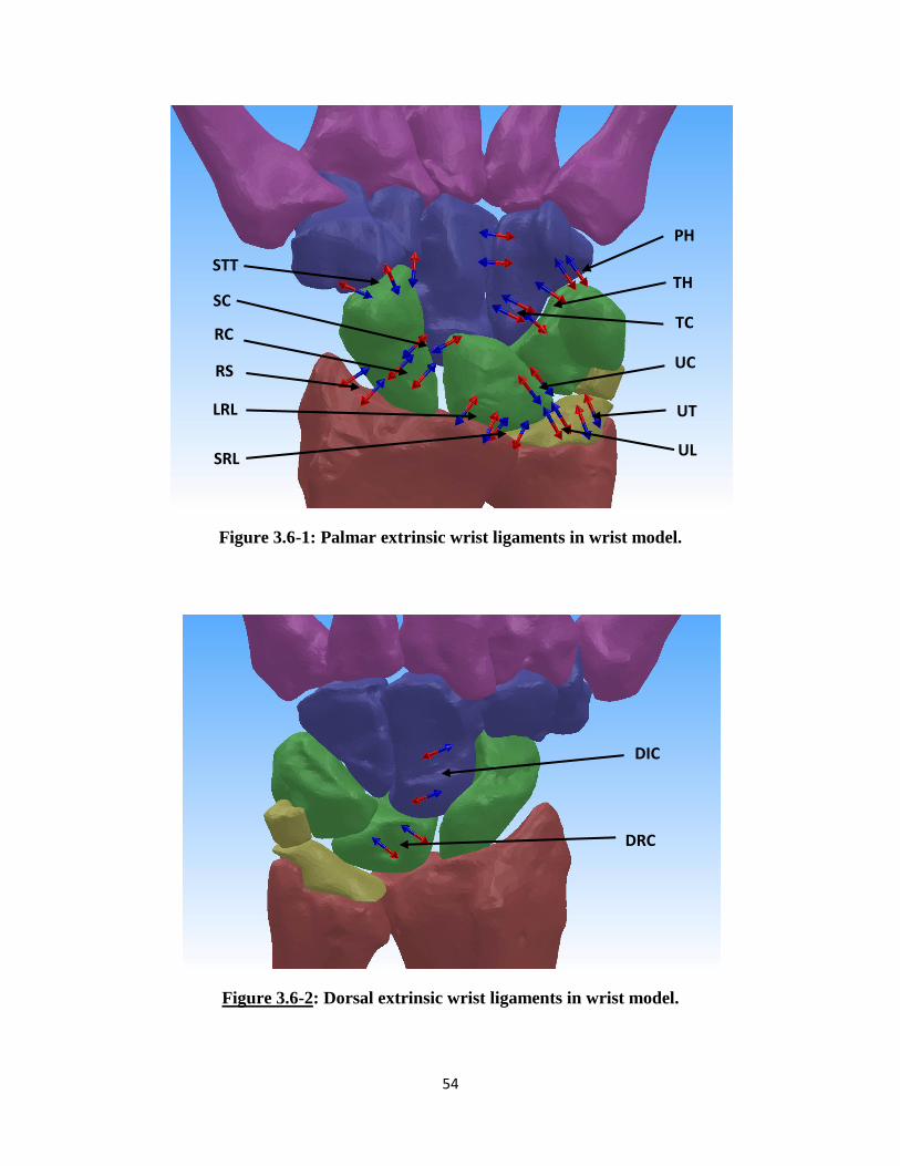
54
Figure 3.6-1: Palmar extrinsic wrist ligaments in wrist model.
Figure 3.6-2: Dorsal extrinsic wrist ligaments in wrist model.
STT
RS
RC
SC
LRL
SRL UL
UT
UC
TC
TH
PH
DRC
DIC

55
Figure 3.6-3: Palmar intrinsic wrist ligaments in wrist model.
Figure 3.6-4: Dorsal intrinsic wrist ligaments in wrist model.
TT
SC
STT
SL
LT
TC
TH
CH
CT
LT
SL
CT
TT
CH

56
Figure 3.6-5: Palmar carpo-metacarpal and metacarpal ligaments in the wrist model.
Figure 3.6-6: Dorsal carpo-metacarpal and metacarpal ligaments in the wrist model.
T-3M
T-2M
C-4M
H-3M
H-4M
H-5M
P-5M
2M-3M
C-4M
H-5M
H-4M
T-3M
T-2M
3M-4M 2M-3M 4M-5M
3M-4M 4M-5M

57
3.6.2 Ligament Mechanical Properties
Once the anatomical locations of the ligaments were identified and the spring elements
incorporated, the mechanical properties were defined. Many experimental cadaveric studies
have been conducted which have tested and determined mechanical properties (stiffness,
modulus, in situ strain and stress free length) of the ligaments. For the purposes of this model,
stiffness values of each ligament were incorporated in the model. Stiffness values were chosen
to drive the behavior of spring elements in SolidWorks Motion to recreate the tissue’s structural
property. Stiffness values were identified from reported results from mechanical experimental
studies. [18], [37], [39], [61], [70] In some experimental studies, the modulus of the ligaments
was reported. [37] These values were converted to stiffness by factoring in the average cross-
sectional area reported for the specific ligaments. Most of the stiffness values were reported
from either load-displacement curves on isolated ligaments or bone-ligament-bone mechanical
tests. While there was some variation in values reported in the literature, specific stiffness value
selections were made for the model based on the investigators’ experimental methodology (Table
3.6-1, Table 3.6-2 and Table 3.6-3).

58
Ligament Name Total Ligament
Stiffness (N/mm)
Radioscaphoid Ligament (RS) 50 [18], [48]
Radiocapitate Ligament (RC) 50 [18], [46], [48]
Long Radiolunate Ligament (LRL) 37.5 [37], [39]
Short Radiolunate Ligament (SRL) 37.5 [37], [39]
Ulnolunate Ligament (UL) 40 [18], [37]
Ulnocapitate Ligament (UC) 50 [18]
Ulnotriquetrum Ligament (UT) 40 [18]
Dorsal Radiocarpal Ligament (DRC) 75 [37], [39]
Table 3.6-1– Extrinsic ligament stiffness values defined for 3D wrist model
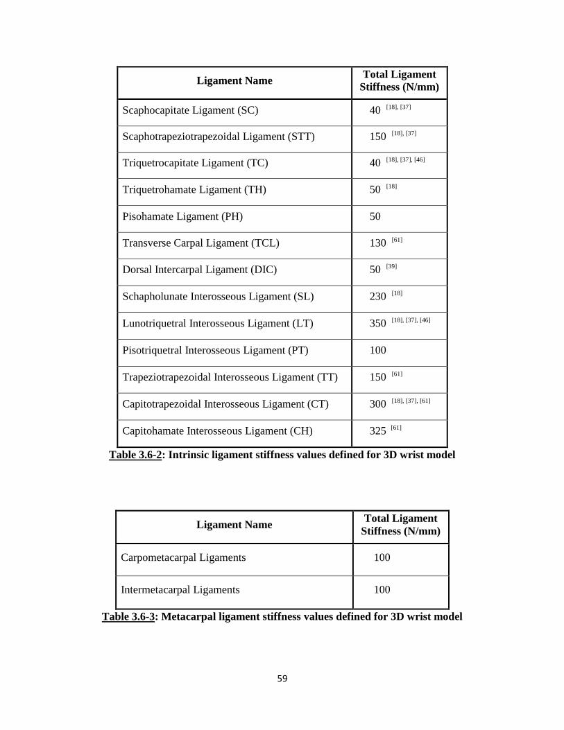
59
Ligament Name Total Ligament
Stiffness (N/mm)
Scaphocapitate Ligament (SC) 40 [18], [37]
Scaphotrapeziotrapezoidal Ligament (STT) 150 [18], [37]
Triquetrocapitate Ligament (TC) 40 [18], [37], [46]
Triquetrohamate Ligament (TH) 50 [18]
Pisohamate Ligament (PH) 50
Transverse Carpal Ligament (TCL) 130 [61]
Dorsal Intercarpal Ligament (DIC) 50 [39]
Schapholunate Interosseous Ligament (SL) 230 [18]
Lunotriquetral Interosseous Ligament (LT) 350 [18], [37], [46]
Pisotriquetral Interosseous Ligament (PT) 100
Trapeziotrapezoidal Interosseous Ligament (TT) 150 [61]
Capitotrapezoidal Interosseous Ligament (CT) 300 [18], [37], [61]
Capitohamate Interosseous Ligament (CH) 325 [61]
Table 3.6-2: Intrinsic ligament stiffness values defined for 3D wrist model
Ligament Name Total Ligament
Stiffness (N/mm)
Carpometacarpal Ligaments 100
Intermetacarpal Ligaments 100
Table 3.6-3: Metacarpal ligament stiffness values defined for 3D wrist model

60
As previously indicated, ligaments were represented as tension only spring elements in
the model. In SolidWorks Motion, this was represented as an action-reaction force vector that
spanned between the two defined insertion points for each element. The mechanical properties
of the force vectors were defined by a custom FORTRAN code. This code was written as a
standard If statement and was dependent on the stiffness, current ligament length and the initial
ligament length, as shown in Equation 3.6-1.
If((LL)-(LL0):0,0,St*((LL)-(LL0))) Equation 3.6-1
Where, LL = Ligament Length
LL0 = Zero Ligament Length
St = Stiffness
The real-time ligament length at each time step was measured during a simulation and
compared that to the stress free zero ligament length. The zero ligament length was defined as
the initial length of the spring element between the two attachment points in the wrist neutral
orientation. If the ligament length was greater than the zero length, then a force proportional to
the difference would be generated. If the ligament length was equal to or shorter than the zero
length, then no force would exist.
Along with the force vectors, each of the elements also included a damper. The damper
functioned to prevent rapid changes in length and force during computation which could result in
unrealistic results or even convergence failure. A linear damper was applied to all force vectors
with a coefficient of 0.25 N-s/mm. While the damping element does slow down changes
experienced within the system, it does not affect the final results. However, due to the damping
effect, sufficient time must be provided for the results to converge to the final solution. Overall,
the only difference seen in the incorporation of the dampers was an increase in the time domain.
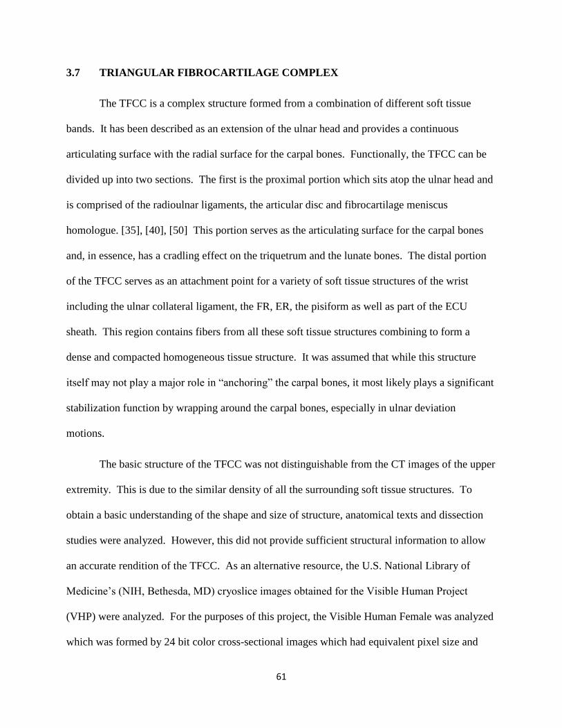
61
3.7 TRIANGULAR FIBROCARTILAGE COMPLEX
The TFCC is a complex structure formed from a combination of different soft tissue
bands. It has been described as an extension of the ulnar head and provides a continuous
articulating surface with the radial surface for the carpal bones. Functionally, the TFCC can be
divided up into two sections. The first is the proximal portion which sits atop the ulnar head and
is comprised of the radioulnar ligaments, the articular disc and fibrocartilage meniscus
homologue. [35], [40], [50] This portion serves as the articulating surface for the carpal bones
and, in essence, has a cradling effect on the triquetrum and the lunate bones. The distal portion
of the TFCC serves as an attachment point for a variety of soft tissue structures of the wrist
including the ulnar collateral ligament, the FR, ER, the pisiform as well as part of the ECU
sheath. This region contains fibers from all these soft tissue structures combining to form a
dense and compacted homogeneous tissue structure. It was assumed that while this structure
itself may not play a major role in “anchoring” the carpal bones, it most likely plays a significant
stabilization function by wrapping around the carpal bones, especially in ulnar deviation
motions.
The basic structure of the TFCC was not distinguishable from the CT images of the upper
extremity. This is due to the similar density of all the surrounding soft tissue structures. To
obtain a basic understanding of the shape and size of structure, anatomical texts and dissection
studies were analyzed. However, this did not provide sufficient structural information to allow
an accurate rendition of the TFCC. As an alternative resource, the U.S. National Library of
Medicine’s (NIH, Bethesda, MD) cryoslice images obtained for the Visible Human Project
(VHP) were analyzed. For the purposes of this project, the Visible Human Female was analyzed
which was formed by 24 bit color cross-sectional images which had equivalent pixel size and

62
image intervals generating cubic voxels. The image deck was processed within MIMICS. The
TFCC was visually identified within the image deck and analyzed to obtain a more structural
understanding of the entire structure. This rendition, however, could not be incorporated within
the 3D wrist model due to the significant size differences and joint space differences between the
referenced specimens. The basic understanding from this analysis was used to generate 3D
bodies replicating the TFCC and the functional role it is assumed to play within the wrist.
For the purposes of this model, the TFCC was represented as two distinct structures to
accurately replicate the two different roles described above. To recreate the structures in the
SolidWorks design space, two 3D body structures were extracted out of MIMICS in a similar
manner as previously described for the carpal bones.
For the distal portion of the TFCC, a 3D body was captured and formulated in a similar
manner as for the bones. However, this body was formulated to be thicker than it anatomically
exists within the joint. The thicker body was created by activating additional pixels on the lateral
aspect of the body throughout the mask. This was done to allow SolidWorks to recreate the
wrapping, stabilizing role that this portion of the tissue is assumed to play in the human wrist.
For the proximal portion of the TFCC, it was formulated in an anatomically correct manner,
based on descriptions in the literature and renditions in anatomical texts. Both of these 3D
bodies were then imported into the SolidWorks model and positioned in their anatomically
correct orientations.
In terms of the proximal TFCC 3D body (Figure 3.7-1), its purpose was to provide an
even articular surface on the ulnar aspect for the carpal bones. It was replicated to act as an
extension of the ulnar head. Using the RBM method, structures cannot be represented as flexible
bodies. All bodies within the system must be defined as rigid incompressible structures.

63
Anatomically, this proximal portion of the TFCC most likely experiences some deformation
during wrist motion. However, to replicate the function of an even surface of the articular joint
and its cradling effect on the carpal bones, minimal deformation was assumed. Thus, the
proximal TFCC was defined as a rigid body solid structure.
Additionally, in the human wrist joint, the TFCC has soft tissue attachment points to the
ulnar head and the radius. While functionally, the TFCC most likely does not move as one unit
with the ulnar head, minimal movement with just flexion/extension and radial/ulnar deviation of
the carpus was assumed. With forearm pronation/supination, significant motion would occur
between the TFCC and the ulnar head due to rotation within the sigmoid notch. In the
SolidWorks design space, the radius and ulna are fixed relative to each other, so no such motion
can occur. Thus, it can be assumed that the proximal TFCC and the ulnar head function as one
unit. To replicate this, the proximal TFCC was fixed to the ulnar head to ensure no motion was
experienced relative to the forearm long bones.
In terms of the distal TFCC, it was modeled in a thicker manner than it anatomically
exists. This was done to allow the modeling software to calculate contact force and recreate the
wrapping stabilizing effect in the model. Anatomically, this portion of the TFCC undergoes
significant deformation during the wrist motions. This structure is a complex attachment site for
the surrounding ligaments and capsular structures. Tissues from the dorsal/volar and
proximal/distal aspect of the wrist blend to form a homogeneous tissue region. It is assumed that
this site provides some ulnar side stability due to its wrapping effect around the carpal bones. To
replicate this wrapping effect, the distal TFCC modeled body is assumed to be rigid and thus
able to impart force on any contacting bone. This body was secured to the proximal TFCC
structure with force vectors. These force vectors ensure the anchoring of the distal TFCC base to

64
the proximal TFCC body yet allow the distal part of the body to move in conjunction with the
wrist.
Figure 3.7-1: Palmar (left) and dorsal (right) aspect of the model to show TFCC as a two
part structure and the force vectors defined to connect the structures
Distal TFCC body
Proximal TFCC body

65
3.8 CAPSULAR RETINACULAR STRUCTURES
The retinacular structures play a stabilizing role in the wrist joint. As previously
described in Chapter 2, this system is comprised of a number of different portions and layers.
While in the distal portions, distinct attachment points on the carpal and metacarpal bones can be
identified, the proximal portion has been described as more of a continuous sheath that wraps
around the distal radial and ulnar head. While the role of these soft tissue structures may not be
absolutely clear, it can be assumed that it plays a larger role in stabilization, especially in
deficient or injured wrists.
The distal portion of the flexor retinaculum (FR) has distinct attachment points that have
been identified and discussed in the literature. This structure has also been extensively studied
due to the high interest in the carpal tunnel. When modeling the distal FR, better identified as
the transverse carpal ligament (TCL), the structure has attachment points on the lateral side of
the hand spanning from the scaphoid tuberosity to the ridge of the trapezium. On the medial
aspect of the hand, the ligament attaches to the pisiform and the hook of hamate. Thus, this
structure was modeled as a simple linear spring element as described for all the other ligaments.
Four attachment points were identified on the carpal bones based on anatomical descriptions.
The structure was represented with four force vectors with each attachment point being used for
two different spring elements. Two of the spring elements spanned horizontally, while the other
two spring elements spanned diagonally crossing the palmar aspect of the carpus (Figure 3.8-1).

66
Figure 3.8-1: Modeling of TCL (distal FR) on palmar aspect of wrist
The proximal portions of the FR and extensor retinaculum (ER) do not have any distinct
insertion points on the carpal bones. However, these do encapsulate the proximal row of the
carpal bones and thus play a role in stabilization by wrapping around the bones. This band of
tissue also encapsulates most of the tendons and other muscular and fatty tissue. Thus, the
combined mass of tissue cups around the carpal bones and most likely provides some stability to
this region of the joint.
To accurately replicate this effect, solid body structures were incorporated into the model
(Figure 3.8-2 and Figure 3.8-3). Four solid bodies, two for the palmar aspect and two for the
dorsal aspect, were captured out of MIMICS in a similar fashion as described for the TFCC.
These structures were created to closely conform to the surface geometry of the bones across the
radiocarpal joint. Once these structures were incorporated within the SolidWorks design space,
TCL

67
linear spring elements were used to tether the two palmar structures and the two dorsal structures
to each other (Figure 3.8-2 and Figure 3.8-3). In the human hand, the retinacular structures have
attachment points on the radial styloid process and the ulnar styloid process. On the distal lateral
portion, fibers from these soft tissue structures also embed into the TFCC as well as the pisiform.
On the distal medial aspect, while there are no bony attachment points, the fibers from the FR
and the ER integrate to form a continuous structure. In the model, spring elements were included
in a similar manner to recreate this wrapping effect.
Due to the unique method of modeling rigid bodies in SolidWorks, the four FR and ER
structures were modeled in an anatomically modified manner. As previously discussed,
SolidWorks measures 3D contact force by calculating the volumetric overlap between bodies
during each simulated time step. With very thin structures, SolidWorks may not be able to
accurately model 3D body contact due to the low volume which could lead to dramatic and
unintended results. Thus, when these structures were formulated within MIMICS, they were
modeled to be thicker than they anatomically exist. This was done for the same reason as for the
distal TFCC body. By modeling these structures in this manner, they were capable of imparting
lateral contact forces when the carpal bones interacted with them. However, this increased
thickness may also unnaturally affect the kinematic response of the wrist through its range of
motions. To minimize discrepancies due to these bodies, 3D contact with these structures was
selectively assigned. 3D contact was defined to exist only between the bones and the FR and ER
structures. No 3D contact existed between the individual capsular structures themselves. This
ensured that the only affect experienced by the wrist with the addition of these elements was the
wrapping effect on the carpal bones.
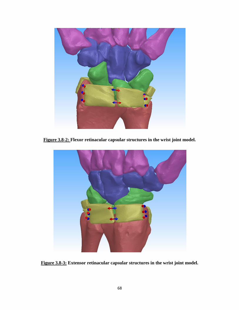
68
Figure 3.8-2: Flexor retinacular capsular structures in the wrist joint model.
Figure 3.8-3: Extensor retinacular capsular structures in the wrist joint model.

69
3.9 WRIST MUSCLES
The wrist has six main muscles that govern its motion. As previously mentioned in
Chapter 2, the APL has a secondary function in wrist motion and was not modeled in any of the
studies covered in this work. The five wrist muscles represented were the ECRL, ECRB, ECU,
FCR, and FCU. In the first experimental study, the ECRB was not simulated. In the second
experimental study, the ECRL and ECRB were sutured together during testing and thus were
considered as one unit. The insertion points of these muscles were obtained from anatomical
texts and similarly marked with points on nodes on the triangular mesh of the respective bone.
Each tendon was modeled with two straight line force vectors representing the lateral and medial
aspects of the tendon. In this case, the force vectors were represented as constant magnitude
force vectors.
One of the main limitations of SolidWorks is the inability to model wrapping of elements
around structures. This proved to be especially challenging when modeling tendons. Tendons
experience dramatic changes in their line of action when a joint goes through its range of motion.
Thus, simply modeling the tendon with a straight line vector connecting the origin and insertion
of the respective muscle was not sufficient. In this case, some further modifications were needed
in order to accurately maintain the line of action of the muscle.
As discussed in Chapter 2, the retinaculum acts as a pulley for the tendons crossing the
wrist joint. Thus, it was determined that by defining the force vector to exist between the wrist
bone insertion point and the region where the tendons cross the retinaculum, the line of action
may sufficiently be preserved for modeling purposes. To achieve this, the distal tendons were
located in the CT scans for the muscles of interest and identified using anatomical text books
(Figure 3.9-1). Once located, the tendons were then extracted in a similar manner as the carpal
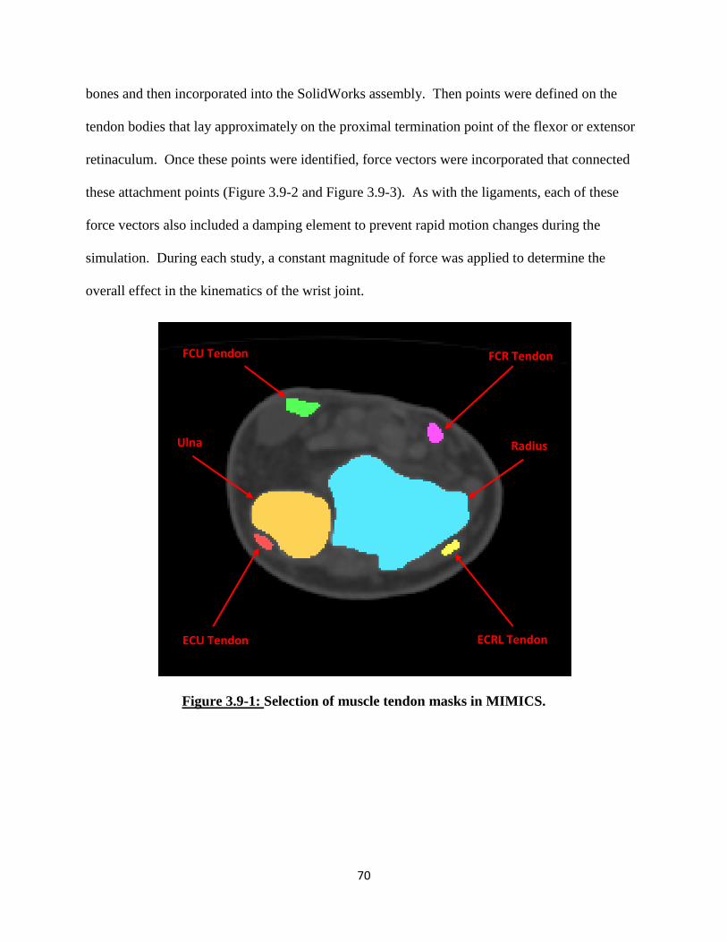
70
bones and then incorporated into the SolidWorks assembly. Then points were defined on the
tendon bodies that lay approximately on the proximal termination point of the flexor or extensor
retinaculum. Once these points were identified, force vectors were incorporated that connected
these attachment points (Figure 3.9-2 and Figure 3.9-3). As with the ligaments, each of these
force vectors also included a damping element to prevent rapid motion changes during the
simulation. During each study, a constant magnitude of force was applied to determine the
overall effect in the kinematics of the wrist joint.
Figure 3.9-1: Selection of muscle tendon masks in MIMICS.
ECRL Tendon ECU Tendon
FCU Tendon FCR Tendon
Ulna Radius
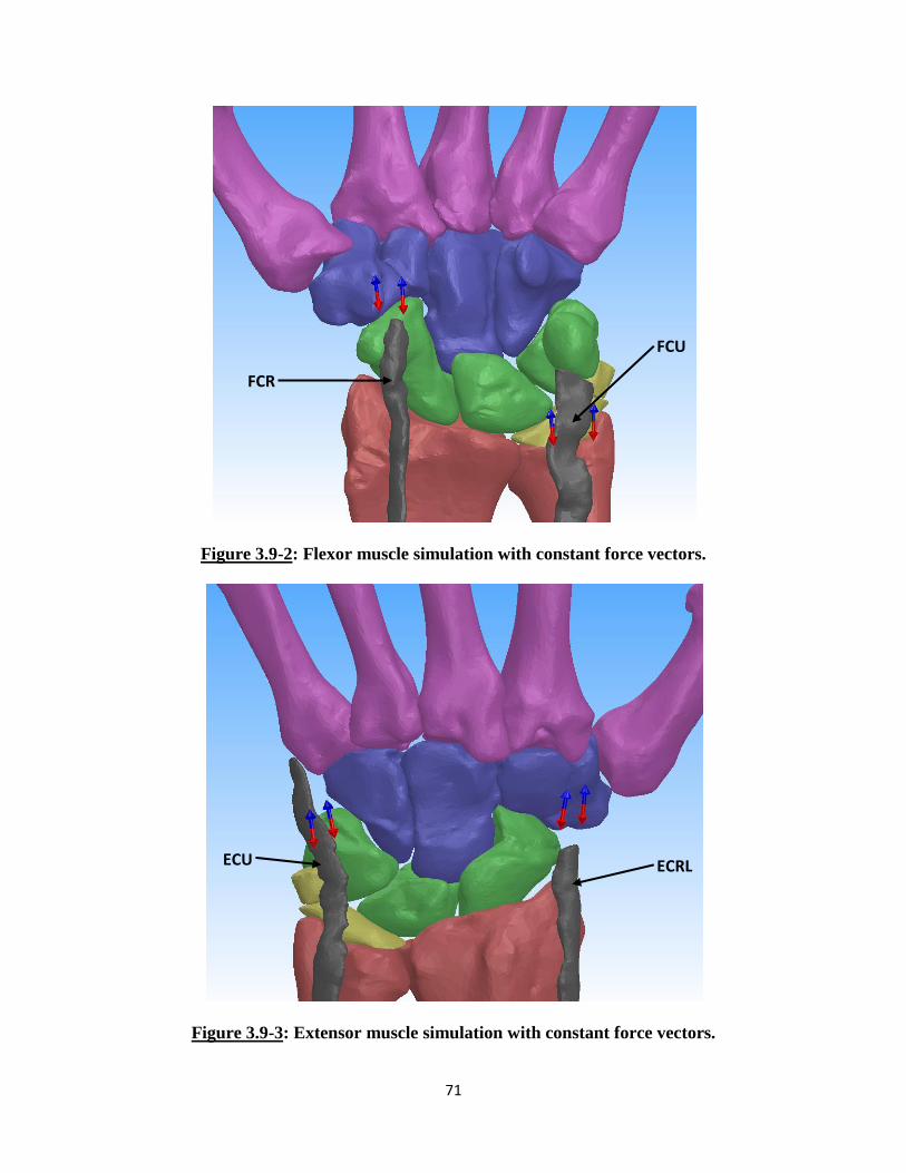
71
Figure 3.9-2: Flexor muscle simulation with constant force vectors.
Figure 3.9-3: Extensor muscle simulation with constant force vectors.
FCU
FCR
ECU ECRL

72
3.10 Complete 3D Wrist Model
The complete 3D wrist model was formulated as described throughout this chapter
(Figure 3.10-1). The bones and articular surfaces were accurately captured and replicated based
on CT images of a joint specimen. The ligaments of the wrist were modeled to mimic
mechanical properties determined from experimental studies reported in the literature. The less
clearly understood TFCC and retinacular capsular structures were recreated to play the roles that
they are assumed to play in wrist stability. Finally, the wrist muscles were represented in a
modified manner to allow the application of force simulating muscle contraction.
Figure 3.10-1: SolidWorks Assembly of the 3D Wrist Model (Ligament force vectors not
shown).
73
CHAPTER 4: RSL RANGE OF MOTION VALIDATION STUDY
4.1 OVERVIEW
The three-dimensional rigid body wrist model was first validated against a cadaveric
experimental study conducted by Pervaiz et al, which analyzed the effects on the kinematics of
the wrist following radioscapholunate (RSL) fusion and carpal bone excisions. [32] The first
version of the 3D wrist model developed by Majors et al [30] was also validated against this
experimental study. For the purpose of this work, the cadaveric experiment was only partially
replicated to demonstrate the reproducibility of the results between the original and updated 3D
wrist model. In this study, only the range of motion for the intact, normal wrist and the wrist
with a RSL fusion procedure were simulated.
RSL fusion is a surgical procedure used for the treatment of radiocarpal arthritis which
may result from cartilage degeneration or following incongruent healing of articular bone
fractures. This treatment option is designed to alleviate the RSL joint pain and stiffness while
still preserving some wrist joint motion [32] It is usually performed when more conservative
options are unable to relieve the pain or stiffness experienced in the joint.
4.2 RSL WRIST RANGE OF MOTION STUDY
The experimental study conducted by Pervaiz et al will be briefly summarized. The
radius and ulna of ten fresh-frozen, upper extremity cadaveric specimens were secured in the
testing apparatus (Figure 4.2-1). Physiological motion of the joint was achieved by loading the
four major muscles of the wrist: the FCR, the FCU, the ECRL and the ECU. Flexion was
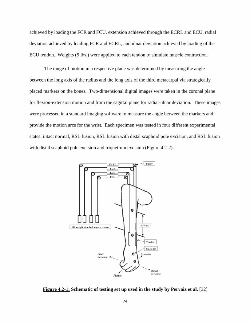
74
achieved by loading the FCR and FCU, extension achieved through the ECRL and ECU, radial
deviation achieved by loading FCR and ECRL, and ulnar deviation achieved by loading of the
ECU tendon. Weights (5 lbs.) were applied to each tendon to simulate muscle contraction.
The range of motion in a respective plane was determined by measuring the angle
between the long axis of the radius and the long axis of the third metacarpal via strategically
placed markers on the bones. Two-dimensional digital images were taken in the coronal plane
for flexion-extension motion and from the sagittal plane for radial-ulnar deviation. These images
were processed in a standard imaging software to measure the angle between the markers and
provide the motion arcs for the wrist. Each specimen was tested in four different experimental
states: intact normal, RSL fusion, RSL fusion with distal scaphoid pole excision, and RSL fusion
with distal scaphoid pole excision and triquetrum excision (Figure 4.2-2).
Figure 4.2-1: Schematic of testing set up used in the study by Pervaiz et al. [32]
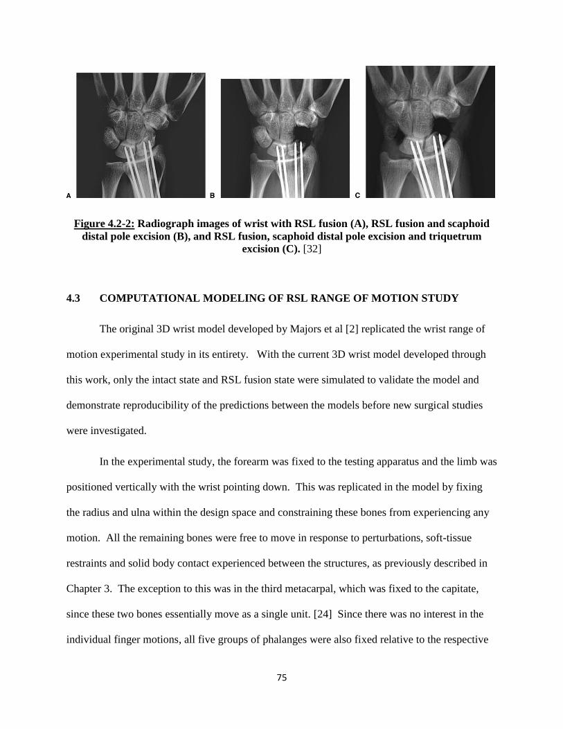
75
Figure 4.2-2: Radiograph images of wrist with RSL fusion (A), RSL fusion and scaphoid
distal pole excision (B), and RSL fusion, scaphoid distal pole excision and triquetrum
excision (C). [32]
4.3 COMPUTATIONAL MODELING OF RSL RANGE OF MOTION STUDY
The original 3D wrist model developed by Majors et al [2] replicated the wrist range of
motion experimental study in its entirety. With the current 3D wrist model developed through
this work, only the intact state and RSL fusion state were simulated to validate the model and
demonstrate reproducibility of the predictions between the models before new surgical studies
were investigated.
In the experimental study, the forearm was fixed to the testing apparatus and the limb was
positioned vertically with the wrist pointing down. This was replicated in the model by fixing
the radius and ulna within the design space and constraining these bones from experiencing any
motion. All the remaining bones were free to move in response to perturbations, soft-tissue
restraints and solid body contact experienced between the structures, as previously described in
Chapter 3. The exception to this was in the third metacarpal, which was fixed to the capitate,
since these two bones essentially move as a single unit. [24] Since there was no interest in the
individual finger motions, all five groups of phalanges were also fixed relative to the respective

76
metacarpal bone. Additionally, an external force was applied to the wrist parallel to the coronal
plane pointing along the distal axis of the arm to replicate the gravitational force experienced by
the limb during the experimental study (Figure 4.3-1). A native tool exists within SolidWorks
Motion which simulates the effect of gravity on individual parts or at the assembly level within
the design space. Once the direction of action was defined, the tool applies a linear acceleration
to the centroid of each body within the assembly to replicate gravitational effects.
Figure 4.3-1: Wrist model with radius and ulna fixed and gravity defined (green arrow)
for RSL Fusion study
In the experimental study, no surgical alterations were performed to the specimens in the
intact state. Thus, all the structures described in Chapter 3 were included in the wrist model for
the simulation of this part of the study. To replicate the 5 lb weight applied to the tendons during

77
the experimental study, constant force vectors with a total magnitude of 22.24N were applied to
each respective tendon in the wrist model. To achieve the motion arcs in the wrist model, the
FCU and the FCR were loaded for flexion, the ECU and ECRL for extension, the FCR and
ECRL for radial deviation and the ECU loaded for ulnar deviation.
Once testing was simulated in all four motions in the intact state, adjustments were
performed on the wrist model to accurately replicate the RSL fusion state achieved in the
experimental study. The carpal bone fusion was replicated by utilizing the “mate” tool native to
SolidWorks in which the scaphoid and lunate were locked in their neutral orientation relative to
the radius. This prevented any motion of these bones during simulations (Figure 4.3-2) and
essentially eliminated motion at the radiocarpal joint. All the remaining bones and structures of
the wrist were free to move as previously defined. Once this fusion state was achieved, the
motion studies were carried out in an identical manner as described for the intact state to
examine the observed changes in the range of motion angles.

78
Figure 4.3-2: Simulated fusion of scaphoid and lunate to radius (Capsular structures
hidden for clarity).

79
4.4 RESULTS
In the experimental cadaveric study conducted by Pervaiz et al, the angles of motion were
measured from 2D images taken in the coronal plane for flexion/extension and images in the
sagittal plane for radial/ulnar deviation. Angles were measured between markers placed along
the long axis of the radius and the third metacarpal. A comparable approach was taken to
measure the motion angles in the computational model. First the long axis of the radius and the
third metacarpal were defined based on anatomical landmarks and definitions provided by ISB
[63] and as discussed in Chapter 3. The angle formed between these two reference lines is the
most widely accepted method of determining global wrist joint angle. However, the
experimental study measured wrist angles from a 2D perspective. Thus, the 3D angles formed
between the axes of the bones within the computational model were processed to reflect a 2D
perspective of the motion of interest. To achieve this, for flexion and extension, a projection of
the wrist coronal plane was created upon which two lines were drawn and defined to be parallel
to the long axis of the radius and the third metacarpal (Figure 4.4-1). These lines traced the
motions of the long axes in a 2D manner and thus, the angles between these lines could be
tracked to determine the flexion/extension motion angle of the wrist joint during a simulation
(Figure 4.4-3). For radial/ulnar deviation a similar method was employed, but in this case a
projection of the wrists sagittal plane was created (Figure 4.4-2) and the angle between the
defined lines was traced to give the joint motion angle (Figure 4.4-4).
Validation of the 3D wrist model was carried out against the four range of motion results
obtained in the two different states (intact normal and RSL fusion) of the cadaveric experimental
study. These results were further compared with the wrist motions predicted by the
computational model developed by Majors et al (Figure 4.5-1 – Figure 4.5-4). [30]

80
Figure 4.4-1: Projected coronal plane to measure wrist flexion/extension angles (Capsular
structures hidden for clarity).
Figure 4.4-2: Projected sagittal plane to measure wrist radial/ulnar deviation angles
(Capsular structures hidden for clarity).
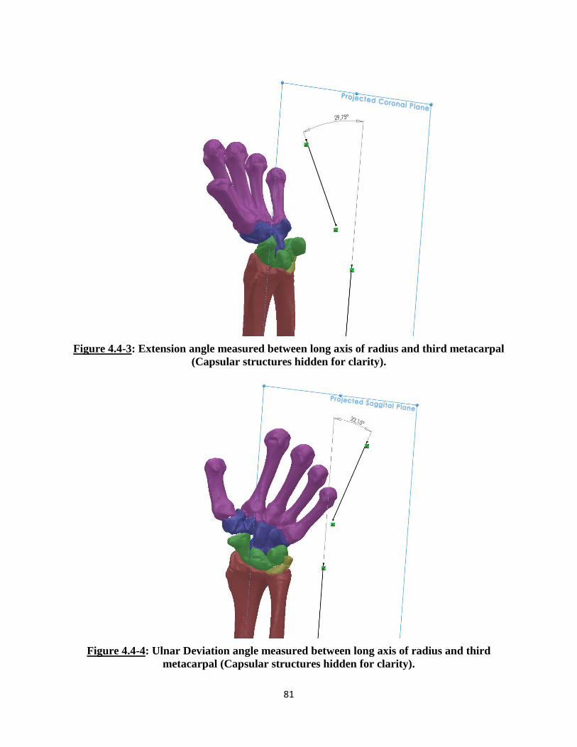
81
Figure 4.4-3: Extension angle measured between long axis of radius and third metacarpal
(Capsular structures hidden for clarity).
Figure 4.4-4: Ulnar Deviation angle measured between long axis of radius and third
metacarpal (Capsular structures hidden for clarity).
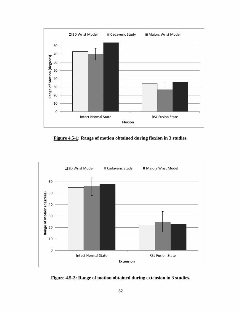
82
Figure 4.5-1: Range of motion obtained during flexion in 3 studies.
Figure 4.5-2: Range of motion obtained during extension in 3 studies.
0
10
20
30
40
50
60
70
80
Intact Normal State RSL Fusion State
Ran
ge o
f M
oti
on
(d
egr
ee
s)
Flexion
3D Wrist Model Cadaveric Study Majors Wrist Model
0
10
20
30
40
50
60
Intact Normal State RSL Fusion State
Ran
ge o
f M
oti
on
(d
egr
ee
s)
Extension
3D Wrist Model Cadaveric Study Majors Wrist Model

83
Figure 4.5-3: Range of motion obtained during radial deviation in 3 studies.
Figure 4.5-4: Range of motion obtained during ulnar deviation in 3 studies.
0
5
10
15
20
25
30
35
Intact Normal State RSL Fusion State
Ran
ge o
f M
oti
on
(d
egr
ee
s)
Radial Deviation
3D Wrist Model Cadaveric Study Majors Wrist Model
0
5
10
15
20
25
30
35
40
Intact Normal State RSL Fusion State
Ran
ge o
f M
oti
on
(d
egr
ee
s)
Ulnar Deviation
3D Wrist Model Cadaveric Study Majors Wrist Model
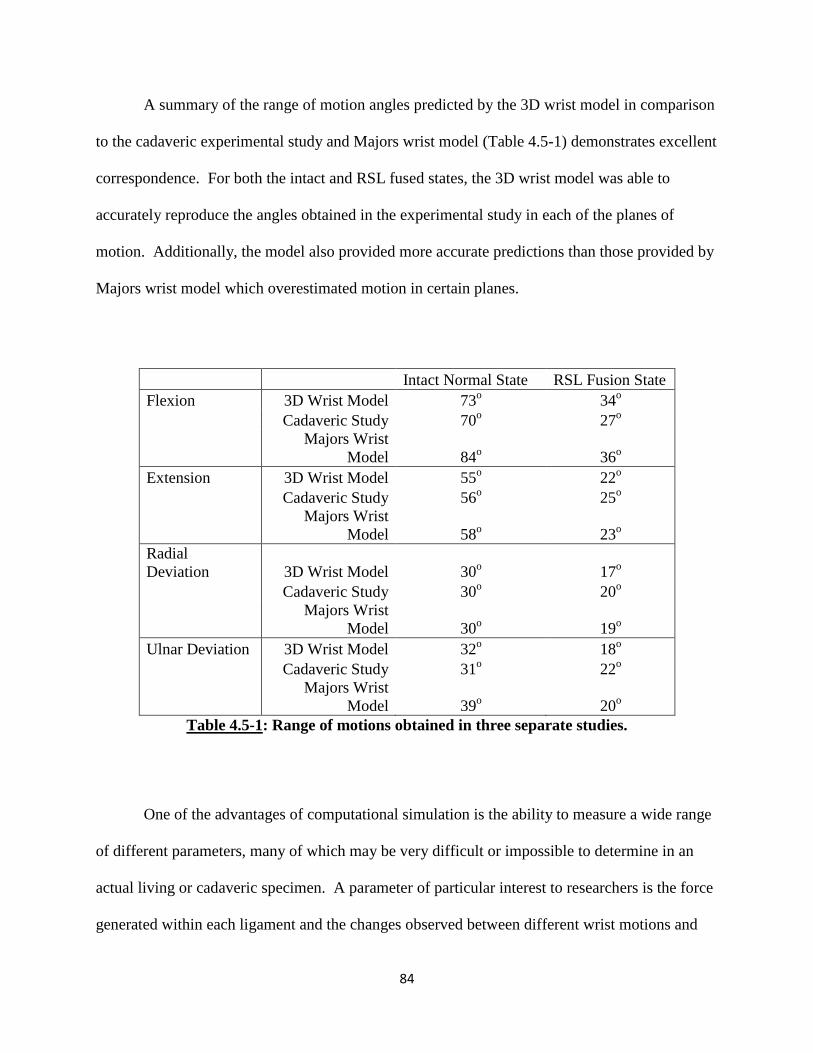
84
A summary of the range of motion angles predicted by the 3D wrist model in comparison
to the cadaveric experimental study and Majors wrist model (Table 4.5-1) demonstrates excellent
correspondence. For both the intact and RSL fused states, the 3D wrist model was able to
accurately reproduce the angles obtained in the experimental study in each of the planes of
motion. Additionally, the model also provided more accurate predictions than those provided by
Majors wrist model which overestimated motion in certain planes.
Intact Normal State RSL Fusion State
Flexion 3D Wrist Model 73o 34
o
Cadaveric Study 70o 27
o
Majors Wrist
Model 84o 36
o
Extension 3D Wrist Model 55o 22
o
Cadaveric Study 56o 25
o
Majors Wrist
Model 58o 23
o
Radial
Deviation 3D Wrist Model 30o 17
o
Cadaveric Study 30o 20
o
Majors Wrist
Model 30o 19
o
Ulnar Deviation 3D Wrist Model 32o 18
o
Cadaveric Study 31o 22
o
Majors Wrist
Model 39o 20
o
Table 4.5-1: Range of motions obtained in three separate studies.
One of the advantages of computational simulation is the ability to measure a wide range
of different parameters, many of which may be very difficult or impossible to determine in an
actual living or cadaveric specimen. A parameter of particular interest to researchers is the force
generated within each ligament and the changes observed between different wrist motions and
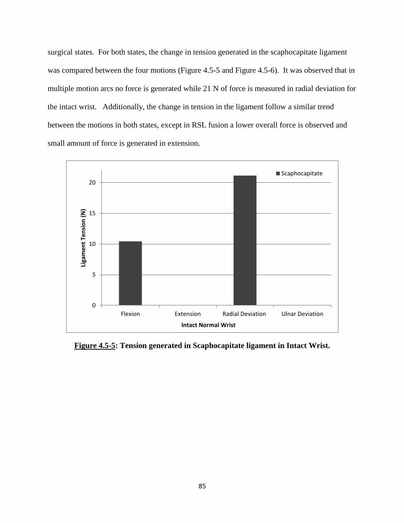
85
surgical states. For both states, the change in tension generated in the scaphocapitate ligament
was compared between the four motions (Figure 4.5-5 and Figure 4.5-6). It was observed that in
multiple motion arcs no force is generated while 21 N of force is measured in radial deviation for
the intact wrist. Additionally, the change in tension in the ligament follow a similar trend
between the motions in both states, except in RSL fusion a lower overall force is observed and
small amount of force is generated in extension.
Figure 4.5-5: Tension generated in Scaphocapitate ligament in Intact Wrist.
0
5
10
15
20
Flexion Extension Radial Deviation Ulnar Deviation
Liga
me
nt
Ten
sio
n (
N)
Intact Normal Wrist
Scaphocapitate

86
Figure 4.5-6: Tension generated in Scaphocapitate ligament in RSL Fusion Wrist.
Additional measurements were made to determine the changes in tension observed within
particular ligaments. A comparison of the changes in force observed pre- and post-operatively
was conducted for all four wrist motions (Figure 4.5-7 – Figure 4.5-11). In flexion, a dramatic
drop in the DRC tension and an increase in the TC and DIC tension is observed in post-op. In
extension, large drops in ligament tension is observed in the RC and UL ligaments and new force
is generated in the SC ligament. In radial deviation, minimal changes occur in UT, a drop in
tension is observed in SC and force is generated in UC post-op. Finally, in ulnar deviation, a
drop in tension generation is observed in both the STT and the DIC ligaments.
0
2
4
6
8
10
12
Flexion Extension Radial Deviation Ulnar Deviation
Liga
me
nt
Ten
sio
n (
N)
RSL Fusion Wrist
Scaphocapitate

87
Figure 4.5-7: Comparison of tension generated in wrist ligaments during flexion.
Figure 4.5-8: Comparison of tension generated in wrist ligaments during extension.
0
5
10
15
20
25
30
INTACT RSL FUSION
Flexion
Liga
me
nt
Ten
sio
n (
N)
Triquetrocapitate Dorsal Intercarpal Dorsal Radiocarpal Scaphocapitate
0
2
4
6
8
10
12
14
INTACT RSL FUSION
Extension
Liga
me
nt
Ten
sio
n (
N)
Radiocapitate Scaphocapitate Ulnocapitate

88
Figure 4.5-9: Comparison of tension generated in wrist ligaments during radial deviation.
Figure 4.5-10: Comparison of tension generated in wrist ligaments during ulnar deviation.
0
5
10
15
20
INTACT RSL FUSION
Radial Deviation
Liga
me
nt
Ten
sio
n (
N)
Ulnocapitate Ulnotriquetral Scaphocapitate
0
2
4
6
8
10
12
14
16
INTACT RSL FUSION
Ulnar Deviation
Liga
me
nt
Ten
sio
n (
N)
Scaphotrapezium Trapezoid Dorsal Intercarpal

89
CHAPTER 5: BIOMECHANICS OF THE WRIST FOLLOWING
PROXIMAL ROW CARPECTOMY
5.1 OVERVIEW
Following the validation of the experimental range of motion study by Pervaiz et al, two
additional experimental studies were replicated with the three-dimensional (3D) wrist model.
Both studies investigated the biomechanical effects of a proximal row carpectomy (PRC)
procedure on the human wrist joint. The first study, by Blankenhorn et al, [33] looked at the
effects on carpal kinematics while the second study, by Tang et al, [34] compared the changes in
contact biomechanics in a wrist following a PRC procedure. Both these experimental studies
were conducted within the same laboratory utilizing a similar testing apparatus and
methodology.
The cadaveric experimental studies conducted this motion sparing surgical procedure
which is used as a treatment for certain advanced wrist degenerative conditions. PRC has been
found to be a clinically useful treatment for conditions such as scapholunate advanced collapse,
scaphoid nonunion advanced collapse, chronic perilunate dislocation and Kienbock’s disease.
While clinical studies have shown that a wrist demonstrates a decreased range of motion
following PRC, [71–73] the procedure has been found to have fewer complications, can be easier
to perform and provides similar grip strength and greater pain relief as compared to limited wrist
arthrodesis. [33]
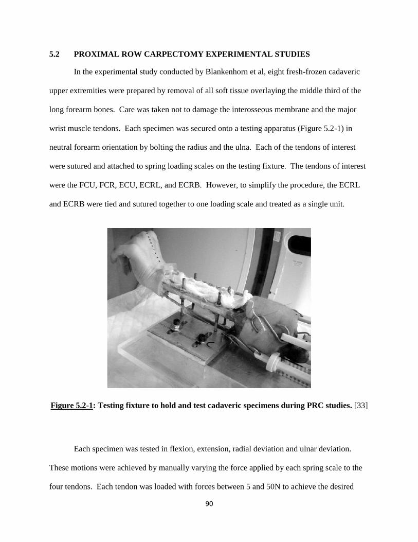
90
5.2 PROXIMAL ROW CARPECTOMY EXPERIMENTAL STUDIES
In the experimental study conducted by Blankenhorn et al, eight fresh-frozen cadaveric
upper extremities were prepared by removal of all soft tissue overlaying the middle third of the
long forearm bones. Care was taken not to damage the interosseous membrane and the major
wrist muscle tendons. Each specimen was secured onto a testing apparatus (Figure 5.2-1) in
neutral forearm orientation by bolting the radius and the ulna. Each of the tendons of interest
were sutured and attached to spring loading scales on the testing fixture. The tendons of interest
were the FCU, FCR, ECU, ECRL, and ECRB. However, to simplify the procedure, the ECRL
and ECRB were tied and sutured together to one loading scale and treated as a single unit.
Figure 5.2-1: Testing fixture to hold and test cadaveric specimens during PRC studies. [33]
Each specimen was tested in flexion, extension, radial deviation and ulnar deviation.
These motions were achieved by manually varying the force applied by each spring scale to the
four tendons. Each tendon was loaded with forces between 5 and 50N to achieve the desired

91
position of the wrist joint. Once a targeted angle was obtained, the spring scale cables were
clamped to the testing fixture to statically maintain the position while CT images of the hand
were obtained. These CT images were used to determine the global wrist joint angles, as well as
the angles observed within the radiocarpal joint and the midcarpal joint.
Each specimen was tested in two different states: intact normal and the PRC wrist. The
PRC procedure was performed by the excision of the scaphoid, lunate and triquetrum with a
dorsal longitudinal incision. Care was taken not to cause any damage to the lunate fossa on the
radial articular surface and the articular head of the capitate. Each of the incisions to the joint
capsule and the skin were re-approximated and repaired using a 2-0 braided suture. Once the
PRC procedure was complete, each wrist specimen was tested in the motions previously
described with the same methodology and tendon forces.
Blankenhorn and colleagues developed a unique software to analyze and measure the
various angles of the wrist joint from CT scans. [33], [74] 3D computer bodies were generated
from the CT scans representing the capitate, lunate and radius for the intact wrists and the
capitate and radius for the PRC wrists. The kinematics positions of the wrist specimens were
determined from bone orientation changes between the neutral scans and scans with the four
motions of interest. In terms of the intact wrist, angular changes in the midcarpal joint, the
radiocarpal joint and global wrist angles were calculated and reported. Following PRC, the
global wrist motion (also referred to as the new radiocarpal joint) was calculated and reported.
In the second study conducted by Tang and colleagues, three pairs of cadaveric upper
extremities were prepared in a similar manner as described above. Each specimen was
radiographically inspected for obvious degeneration and prepared and loaded on the testing
92
fixture with the forearm secured in a neutral position (Figure 5.2-1). The specimens were
secured by bolting the radius and ulna to the test fixture. The flexor and extensor tendons were
sutured and attached to spring loading scales on the testing fixture. Each wrist specimen was
tested in three positions: 45o of flexion, neutral and 45
o of extension. Each wrist position was
achieved by manually varying the force applied to the tendons, with a combined total load
equaling 200N. In the intact state, the tendon loads were varied until the desired wrist angles
were achieved. The wrist angle was verified using a goniometer to measure the angle between
the radius and third metacarpal. Once desired wrist position was achieved, each specimen was
manually secured to prevent change in joint angle during testing. The manner in which the
specimens were secured in the desired position for each test was not discussed in the publication.
Each specimen was tested in two different states: intact normal and PRC wrist. The PRC
procedure was performed as described in the previous experimental study.
After excision of the carpal bones for the PRC procedure, a radial styloidectomy was
performed with care to preserve the articular surfaces and the radioscaphocapitate ligament. A
radiostyloidectomy was performed to eliminate carpal bone abutment against the radial styloid
process during contact force test. In this case a much higher combined load was applied as
compared to the range of motion study, and so the bones compacted together to a greater extent.
Thus, a styloidectomy was required to reduce undesired bone contact. Once the surgical
alterations were completed, each tendon was loaded with the same amount of force as used in the
intact state. Again, the specimen was manually supported to maintain the desired joint angle and
position while the pressure test was conducted.
For this study, Tang and colleagues investigated the changes in contact pressure between
the bones pre- and post PRC surgery. The contact pressure was measured using Fuji pressure
93
contact film (Fuji Photo Film Co., Ltd., Tokyo, Japan). Two types of contact films were used:
UltraSuperLow film (range 0.2-0.6 MPA) for the intact wrist and Low film (range 2.5-10 MPA)
for the PRC wrist. Each film was calibrated and sealed to protect it from moisture during the
experiments. The films were placed within the radiocarpal joint through a dorsal longitudinal
incision of the wrist. Once the radiocarpal joint was exposed in the intact wrist, a template of the
distal forearm (including the radial articulating surface, TFCC and ulnar head) was created.
These templates were used to create custom shaped Fuji films for each specimen.
Each wrist specimen’s tendons were first loaded with the combined 200N force to
achieve the desired testing position. The exact loads applied to each individual tendon were not
disclosed within the publication. Once the desired position was achieved for the intact wrist, the
carpus was manually distracted to allow placement of the custom shaped UltraSuperLow film
within the radiocarpal joint. The tendon loads were then reapplied for 60 sec, while manually
securing the specimen to ensure that wrist position did not change. The load was then removed
and the carpus distracted to allow for careful removal of the film. To ensure accuracy, this
testing was repeated in each position until three consistent sets of film were obtained. Care was
taken throughout testing to minimize the creation of artifacts on the Fuji film. Once the wrist
specimen was tested in all three positions with consistent results, a PRC and radial styloidectomy
was performed. The testing sequence was then repeated with the same tendon loads at identical
wrist angles. Again, the wrist specimens were manually supported to ensure no motion occurred
during testing. Each Fuji film was analyzed using a custom software developed in MATLAB
(The MathWorks, Inc., Natick, MA). This determined and measured the pressure, contact area
and location of the carpal bones during each test.
94
5.3 COMPUTATIONAL MODELING OF PROXIMAL ROW CARPECTOMY
BIOMECHANICAL STUDIES
As with the range of motion study by Pervaiz et al, the two cadaveric PRC experiments
were replicated with the 3D rigid body wrist model. Testing was recreated within the
SolidWorks space with the model in both the intact state and after a simulated PRC procedure.
All the active muscle forces and soft tissue constraints were replicated from each study within
the model. The simulations provided wrist biomechanical results which were validated against
the findings reported in the two experimental studies.
In the experimental study by Blankenhorn et al, the cadaveric wrist specimens were
secured to a testing fixture with the arm in a horizontal orientation with the palmar aspect facing
the ground. This orientation of the wrist was recreated within the SolidWorks design space by
fixing the radius and ulna in a neutral position and defining the direction of the gravitational
force in the palmar direction along the dorsopalmar axis (Figure 5.3-1). Gravitational force was
replicated with the use of the native SolidWorks Motion tool as described in Chapter 4. As was
done with the RSL fusion range of motion study, all the remaining carpal and metacarpal bones
were permitted to move freely. These bones were only constrained by the defined soft tissue
structures and the bony articulations. Once again, the first and third metacarpal bones were
exceptions to this. The first metacarpal bone was fused to the trapezium bone since it did not
play any role for wrist motion in this study. The third metacarpal was fixed relative to the
capitate since the two bones have been defined to move as one unit.

95
Figure 5.3-1: Wrist model orientation and gravity direction (green arrow) for PRC
experimental studies
The muscle tendon forces were replicated in a similar manner as previously described.
Each tendon was represented with two constant force vectors applied at the respective insertion
points (Figures 3.9-2 and 3.9-3). The magnitudes of the forces applied at each insertion point for
the four wrist motion angles are shown in Table 5.3-1. All four sets of tendons were loaded to
varying degrees to achieve each of the wrist positions.

96
Muscle Name Flexion Extension Radial
Deviation
Ulnar
Deviation
Flexor Carpi Ulnaris 24 N 12 N 20 N 4 N
Flexor Carpi Radialis 24 N 12 N 40 N 5 N
Extensor Carpi
Radialis Longus 12 N 30 N 50 N 5 N
Extensor Carpi
Ulnaris 12 N 30 N 12 N 25N
Table 5.3-1: Muscle load applied to achieve each wrist position
Once all four motions were tested in the intact normal wrist model, a simulated PRC
procedure was conducted to accurately replicate the surgically altered experimental specimens.
First, the scaphoid, lunate and triquetrum bone structures were removed from the design space.
All the remaining bones of the carpus were temporarily locked together to create one unit. The
entire carpus was then moved proximally towards the distal radial articulating head and
positioned such that the proximal capitate head sat upon the lunate fossa of the radial articulating
surface (Figure 5.3-2). The positioning of the carpus was further examined to ensure that the
carpal bones were oriented between the capsular structures and that no structural overlap existed.
Once a satisfactory placement of the distal wrist was achieved, all the bones were then unlocked
from each other. This allowed the bones to move freely in response to any perturbation,
restrained only by the articulating surfaces and the soft tissue structures.
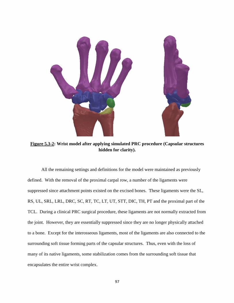
97
Figure 5.3-2: Wrist model after applying simulated PRC procedure (Capsular structures
hidden for clarity).
All the remaining settings and definitions for the model were maintained as previously
defined. With the removal of the proximal carpal row, a number of the ligaments were
suppressed since attachment points existed on the excised bones. These ligaments were the SL,
RS, UL, SRL, LRL, DRC, SC, RT, TC, LT, UT, STT, DIC, TH, PT and the proximal part of the
TCL. During a clinical PRC surgical procedure, these ligaments are not normally extracted from
the joint. However, they are essentially suppressed since they are no longer physically attached
to a bone. Except for the interosseous ligaments, most of the ligaments are also connected to the
surrounding soft tissue forming parts of the capsular structures. Thus, even with the loss of
many of its native ligaments, some stabilization comes from the surrounding soft tissue that
encapsulates the entire wrist complex.

98
With the newly attained PRC wrist state, the model was then tested in the four wrist
motions with the tendon loads used during the intact sate. Flexion, extension, radial and ulnar
deviation angles achieved during each motion was measured.
The experimental set-up for the contact pressure study conducted by Tang et al employed
a similar testing apparatus and methodology. Thus, the study was replicated within SolidWorks
in a very similar manner as the carpal kinematics PRC study. The 3D wrist model’s positioning,
orientation, and structures were all modeled in an identical manner as described for the previous
two studies. However, during the final contact force test simulation, the capsular retinacular
structures and the distal TFCC were removed from the SolidWorks design space. The proximal
TFCC was included in the model as previously described.
The capsular structures and the distal TFCC replicated the soft tissue wrapping effect on
the carpus during joint motion. Based on the testing methodology of this experiment, their
incorporation was not essential for this study. In fact, the incorporation of these structures would
most likely diminish the final contact force experienced between the bones and lead to inaccurate
results. The capsular structures and the TFCC were represented as solid bodies to enable them to
impart contact forces to the carpal bones. This was done to replicate the wrapping effect these
structures anatomically are assumed to perform. This stabilizing effect is most critical when the
joint is going through its kinematic motions. However, during the experimental study, the
specimens were manually maintained at the desired wrist angle. Thus, these tissues were not
able to play the stabilizing role they normally would have performed. Moreover, since the
structures were modeled as solid bodies, forces experienced by the carpal bones would also be
transmitted through these structures instead of just the bones. Thus, inclusion of the soft tissue

99
structures would lead to an inaccurate prediction of the path of force transmission. The manner
in which these structures were removed is discussed in further detail below.
In the contact pressure experimental study, each wrist specimen was tested in three
different positions (45o flexion, neutral, and 45
o extension) and in two different states (intact and
PRC). For each test, the wrist was manually loaded via the tendons to the desired positions with
a combined 200 N load while ensuring the carpus maintained the desired wrist angle. To
replicate this testing sequence, additional restrictions on the computational model had to be
employed to maintain the desired wrist angle during each test.
To replicate the desired restrictions as the experimental study, reference planes were
defined within the SolidWorks design space. During testing in the neutral position, two
additional planes were created to ensure proper orientation of the wrist model. The 3D wrist
model has been designed in an initial resting neutral state. To maintain this neutral state a
medial-lateral plane and an anteriorposterior plane were created and aligned such that the long
axis of the third metacarpal perfectly lined up at the intersection of these two planes. The third
metacarpal long axis was then defined to remain coincident at the intersecting line of these two
planes. This prevented the third metacarpal, and hence the overall wrist, from going into any
flexion/extension or radial/ulnar deviation (Figure 5.3-3). Yet, this set up allowed the carpus to
move along the proximal/distal axis. Once the desired wrist position was achieved and the third
metacarpal was secured within the reference planes, the capsular structures and the distal TFCC
were removed prior to running the contact force test. During the simulated test on the wrist
model, a neutral state was maintained while still allowing carpal bones to interact in a
proximal/distal manner in response to the tendon loads. This procedure was replicated in an
identical manner to test the PRC wrist in the neutral position.
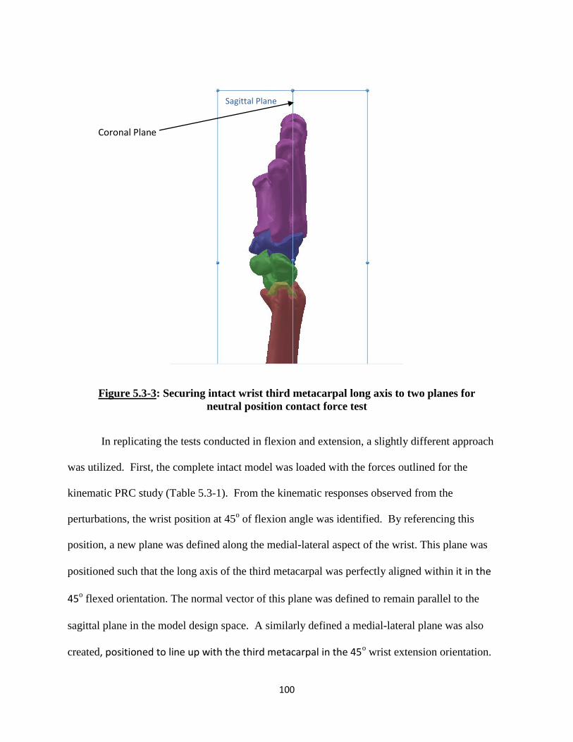
100
Figure 5.3-3: Securing intact wrist third metacarpal long axis to two planes for
neutral position contact force test
In replicating the tests conducted in flexion and extension, a slightly different approach
was utilized. First, the complete intact model was loaded with the forces outlined for the
kinematic PRC study (Table 5.3-1). From the kinematic responses observed from the
perturbations, the wrist position at 45o of flexion angle was identified. By referencing this
position, a new plane was defined along the medial-lateral aspect of the wrist. This plane was
positioned such that the long axis of the third metacarpal was perfectly aligned within it in the
45o flexed orientation. The normal vector of this plane was defined to remain parallel to the
sagittal plane in the model design space. A similarly defined a medial-lateral plane was also
created, positioned to line up with the third metacarpal in the 45o wrist extension orientation.
Coronal Plane
Sagittal Plane
101
With these newly defined planes, the bones of the hand and wrist were reoriented such that these
angular states would be the starting position for the contact pressure test simulation.
The 3D wrist model was formulated such that each simulation always began with the
joint in the neutral resting position. To achieve the desired flexed/extended starting point, the
modeled bones had to be manually repositioned to align up with the defined reference planes.
Since the intact wrist is a compound joint made up of multiple joints, this repositioning had to be
achieved in multiple steps. Since the desired kinematic position had already been identified, the
capsular structures and the distal TFCC were removed from the model. This was acceptable
since the kinematic stabilizing role they performed was no longer required. Next, the entire wrist
was locked together into one unit and was rotated along the dorsal palmar plane around the
centroid of the lunate bone (Figure 5.3-4). The amount of angular motion required was
estimated by visually inspecting the position of the long axis of the third metacarpal and the
reference plane. The proximal carpal row (scaphoid, lunate, triquetrum and pisiform) was then
unlocked from the locked unit. This created a single unit formed by the remaining bones of the
hand. This unit was then angularly rotated in the dorsal palmar plane around the centroid of the
capitate to achieve the overall desired wrist angle (Figure 5.3-5). The desired positioning
required was again determined from visual inspection from a medial/lateral aspect. A small
amount of translation was also required for the entire carpus in the dorsal palmar direction to
achieve the closest possible alignment with the defined plane. To achieve the flexed intact wrist
position, the carpus was rotated 27o around the centroid of the lunate and 17
o around the centroid
of the capitate. Yet, perfect alignment between the long axis of the third metacarpal and the
defined plane was very hard to achieve. This was likely from the fact that wrist motion also
102
incorporates motions in the carpo-metacarpal joint and translational motions of the individual
bones themselves.
Once the manually re-oriented wrist joint was positioned within 1o of the desired angle,
the wrist orientation was determined to be sufficient for the purposes of this test. The defined
45o reference plane was then redefined to align up with the long axis of the third metacarpal in
the flexed wrist joint. Once this was complete, all the bones were unlocked and were free to
move based on the restrictions defined within the model.
The repositioned extended wrist joint was also achieved in a similar manner. With the
defined reference plane, the carpus was rotated around the centroid of the lunate and capitate to
achieve the desired alignment. The carpus was rotated 31o around the lunate and 15
o around the
capitate. Once the wrist angle was positioned with 1o of the desired 45
o extended state, the
reference plane was redefined to perfectly line up with the third metacarpal.
For both the flexion and extension test, the long axis of the third metacarpal was defined
to remain coincident within the newly defined reference plane. This prevented the wrist from
going into any further flexion/extension during the contact force testing. However, the wrist was
still free to move within the anterior-posterior plane or along the proximal/distal axis (Figure 5.3-
6 and Figure 5.3-7).
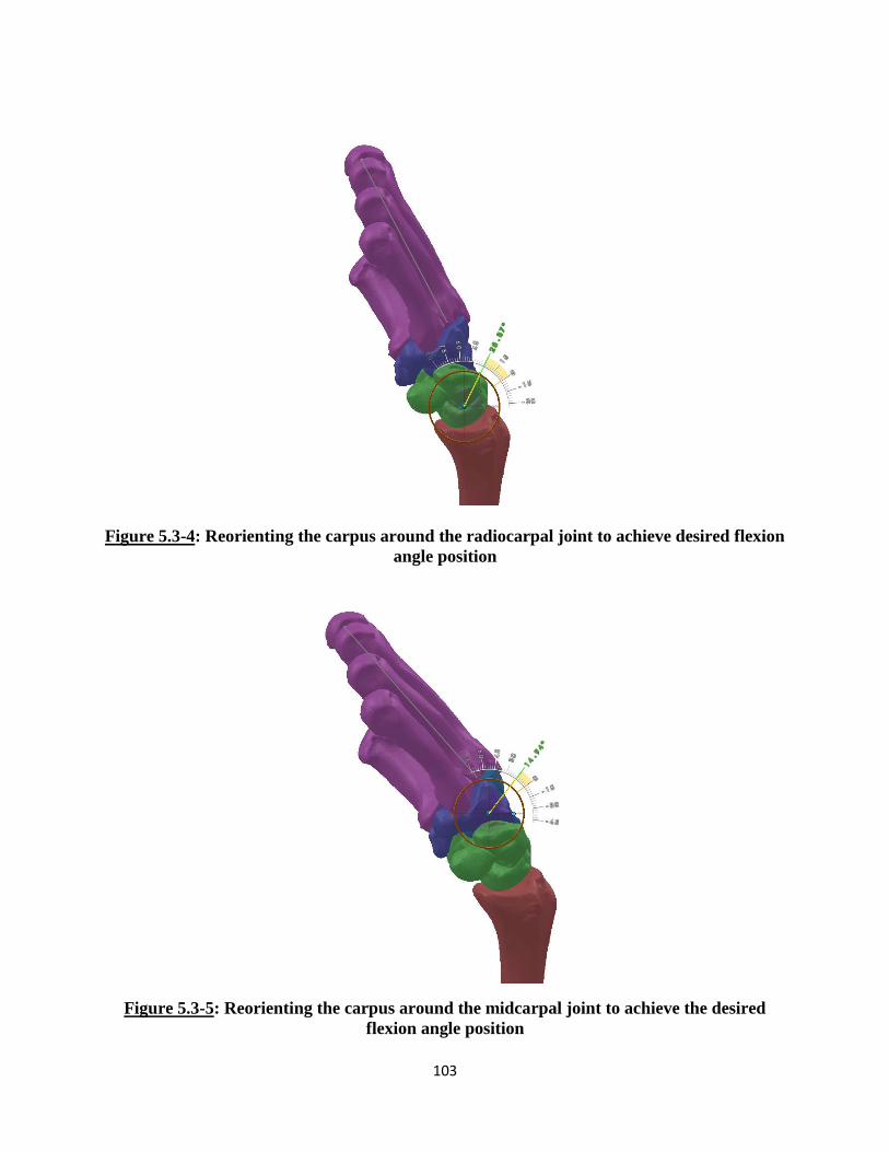
103
Figure 5.3-4: Reorienting the carpus around the radiocarpal joint to achieve desired flexion
angle position
Figure 5.3-5: Reorienting the carpus around the midcarpal joint to achieve the desired
flexion angle position

104
Figure 5.3-6: Securing third metacarpal long axis for flexion position contact force test for
intact wrist
Figure 5.3-7: Securing third metacarpal long axis for extension position contact force test
for the intact wrist
105
With the newly oriented wrist starting positions with the external restrictions imposed,
the wrist tendons were then loaded to replicate the test conducted within the study. The tendon
loads applied for each position was a combined total of 200 N. The individual amounts of loads
applied to each tendon for flexion and extension was based on the ratio at which the loads were
applied to the PRC range of motion test (Table 5.3-2). For the neutral state, slightly higher loads
were applied to the extensor muscle tendons due to the orientation of the hand and its tendency
to go into flexion due to gravity (Table 5.3-2).
Since the starting wrist position for some of the tests was not in the normal neutral resting
state, the model needed a chance to stabilize prior to the application of the external perturbation.
Thus, during each simulation, the tendon loads were defined to be activated one second after the
start of the study. This was important in the cases of the flexion and extension tests. Since the
3D wrist model was designed in a neutral position, all the ligaments and soft tissue structures are
defined by lengths and properties while in the neutral state. During a simulation, if the starting
state of the wrist is of a non-neutral nature, many of the soft tissue structures are no longer in
their defined resting state. Thus, the entire model underwent motion and changes to achieve a
new equilibrium at the new wrist position. Imposition of external forces while this equilibrium
was being achieved can lead to unpredictable results. Thus, a slight delay was provided before
the tendon forces were activated.
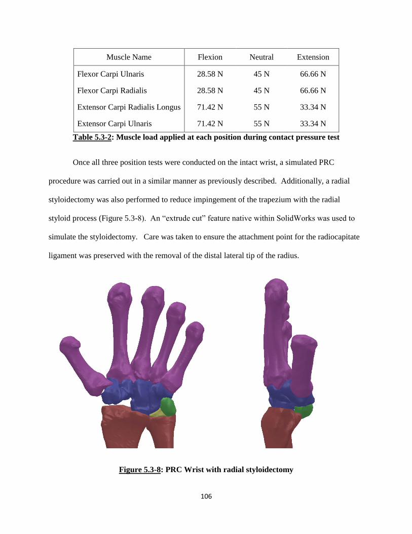
106
Muscle Name Flexion Neutral Extension
Flexor Carpi Ulnaris 28.58 N 45 N 66.66 N
Flexor Carpi Radialis 28.58 N 45 N 66.66 N
Extensor Carpi Radialis Longus 71.42 N 55 N 33.34 N
Extensor Carpi Ulnaris 71.42 N 55 N 33.34 N
Table 5.3-2: Muscle load applied at each position during contact pressure test
Once all three position tests were conducted on the intact wrist, a simulated PRC
procedure was carried out in a similar manner as previously described. Additionally, a radial
styloidectomy was also performed to reduce impingement of the trapezium with the radial
styloid process (Figure 5.3-8). An “extrude cut” feature native within SolidWorks was used to
simulate the styloidectomy. Care was taken to ensure the attachment point for the radiocapitate
ligament was preserved with the removal of the distal lateral tip of the radius.
Figure 5.3-8: PRC Wrist with radial styloidectomy
107
In the PRC state, a similar reorienting method was used to achieve and secure the carpus
in the neutral, 45o of flexion and extension positions. For the neutral state, the PRC wrist was
secured between the intersecting line of the coronal and sagittal planes (Figure 5.3-9). To obtain
the 45o wrist flexion plane, the PRC wrist model tendons were loaded with the forces used for
the PRC kinematic study (Table 5.3-1). The reference plane was obtained in a similar manner as
the intact wrist. The carpus was rotated around the centroid of the capitate (Figure 5.3-10) to
achieve the alignment with the defined reference plane (Figure 5.3-11). For the extension
position, the PRC wrist did not achieve a minimum of 45o extension with the applied loads. The
PRC wrist model tendons were loaded with similar flexor forces as the kinematic study (Table
5.3-1) but with slight higher extensor muscle forces (35 N for ECRL and ECU). This ensured
that the minimum 45o extension position was achieved. The reference plane was then defined
and the carpus reoriented to achieve the desired extended starting position for the PRC wrist
(Figure 5.3-12). The capsular structures and distal TFCC were removed from the design space.
Similar assumptions and corrections were made as described for the reorientation of the intact
wrist. Once the newly oriented positions for the PRC wrist were achieved, the sequence of
testing was then repeated to obtain contact force results with the defined tendon loads (Table 5.3-
2) in the different wrist positions.
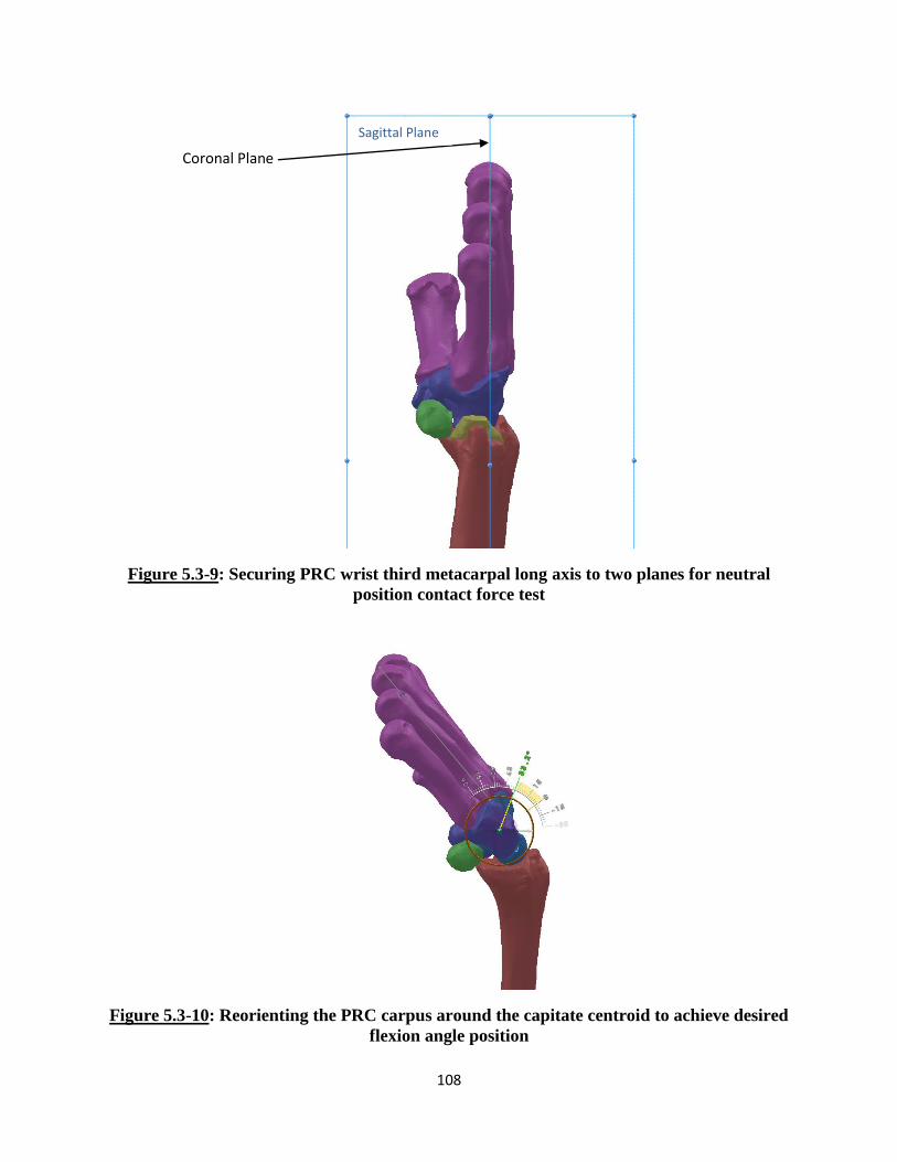
108
Figure 5.3-9: Securing PRC wrist third metacarpal long axis to two planes for neutral
position contact force test
Figure 5.3-10: Reorienting the PRC carpus around the capitate centroid to achieve desired
flexion angle position
Coronal Plane
Sagittal Plane

109
Figure 5.3-11: Securing third metacarpal long axis for flexion position contact force test for
PRC wrist
Figure 5.3-12: Securing third metacarpal long axis for extension position contact force test
for PRC wrist
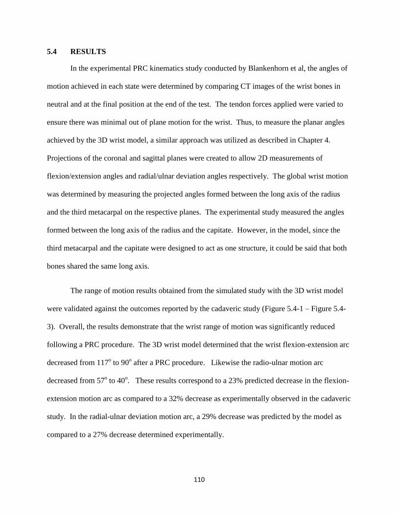
110
5.4 RESULTS
In the experimental PRC kinematics study conducted by Blankenhorn et al, the angles of
motion achieved in each state were determined by comparing CT images of the wrist bones in
neutral and at the final position at the end of the test. The tendon forces applied were varied to
ensure there was minimal out of plane motion for the wrist. Thus, to measure the planar angles
achieved by the 3D wrist model, a similar approach was utilized as described in Chapter 4.
Projections of the coronal and sagittal planes were created to allow 2D measurements of
flexion/extension angles and radial/ulnar deviation angles respectively. The global wrist motion
was determined by measuring the projected angles formed between the long axis of the radius
and the third metacarpal on the respective planes. The experimental study measured the angles
formed between the long axis of the radius and the capitate. However, in the model, since the
third metacarpal and the capitate were designed to act as one structure, it could be said that both
bones shared the same long axis.
The range of motion results obtained from the simulated study with the 3D wrist model
were validated against the outcomes reported by the cadaveric study (Figure 5.4-1 – Figure 5.4-
3). Overall, the results demonstrate that the wrist range of motion was significantly reduced
following a PRC procedure. The 3D wrist model determined that the wrist flexion-extension arc
decreased from 117o to 90
o after a PRC procedure. Likewise the radio-ulnar motion arc
decreased from 57o to 40
o. These results correspond to a 23% predicted decrease in the flexion-
extension motion arc as compared to a 32% decrease as experimentally observed in the cadaveric
study. In the radial-ulnar deviation motion arc, a 29% decrease was predicted by the model as
compared to a 27% decrease determined experimentally.

111
Figure 5.4-1: Total wrist motion arc in intact and PRC wrist
Similar trends in the results can be seen between the values predicted by the 3D wrist
model and the experimental cadaveric study for each of the motions individually (Figure 5.4-2
and Figure 5.4-3). In the intact normal state, the model predicted 72o of flexion, 45
o of
extension, 25o of radial deviation and 32
o of ulnar deviation. Once a simulated PRC procedure
was conducted on the wrist model and kinematics was retested, the model predicted 49o of
flexion, 41o of extension, 15
o of radial deviation, and 25
o of ulnar deviation.
When comparing the angles in each individual wrist motion in the modelled and
experimental results, specific differences can be observed. In terms of flexion, the model results
accurately reproduced the experimental result trends and percent difference. The model
predicted a 32% decrease in flexion after PRC while the experimental results showed a 29%
decrease. In extension, even though a decreasing trend in wrist angle is observed, the model
0
20
40
60
80
100
120
140
Intact PRC Intact PRC
F/E Motion Arc R/U Motion Arc
Ran
ge o
f M
oti
on
(D
egr
ee
s)
Cadaver Study Wrist Model

112
underpredicts the overall percent change. The model predicts a 9% decrease in extension angle
while the experimental study shows an overall decrease of 36%. In terms of radial deviation, a
similar trend is also maintained , with the model predicting a 40% decrease while the cadaveric
results shows a reduction of 45%. Finally, in ulnar deviation, the model predicted the percent
decrease to be at 22% while the study results show a decrease in 15%. While some over and
underprediction is observed by the 3D wrist model, all differences fall within one standard
deviation. Thus, these differences are not significant and the model is able to accurately
replicate the expected kinematics results for such a procedure.
Figure 5.4-2: Flexion and Extension Range of Motion in Intact and PRC Wrist
0
10
20
30
40
50
60
70
80
Intact PRC Intact PRC
Flexion Extension
Ran
ge o
f M
oti
on
(D
egr
ee
s)
Cadaver Study Wrist Model
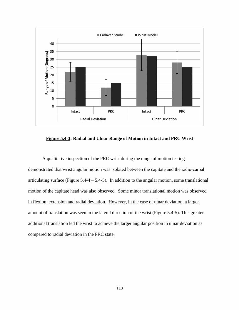
113
Figure 5.4-3: Radial and Ulnar Range of Motion in Intact and PRC Wrist
A qualitative inspection of the PRC wrist during the range of motion testing
demonstrated that wrist angular motion was isolated between the capitate and the radio-carpal
articulating surface (Figure 5.4-4 – 5.4-5). In addition to the angular motion, some translational
motion of the capitate head was also observed. Some minor translational motion was observed
in flexion, extension and radial deviation. However, in the case of ulnar deviation, a larger
amount of translation was seen in the lateral direction of the wrist (Figure 5.4-5). This greater
additional translation led the wrist to achieve the larger angular position in ulnar deviation as
compared to radial deviation in the PRC state.
0
5
10
15
20
25
30
35
40
Intact PRC Intact PRC
Radial Deviation Ulnar Deviation
Ran
ge o
f M
oti
on
(D
egr
ee
s)
Cadaver Study Wrist Model
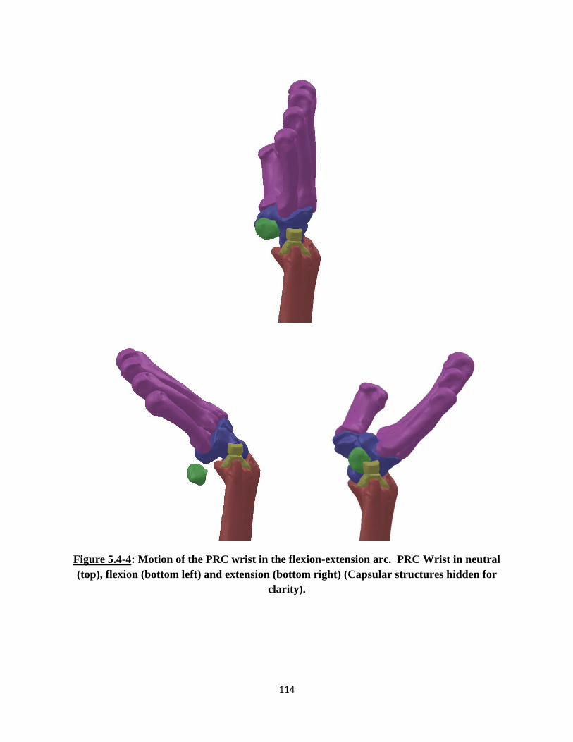
114
Figure 5.4-4: Motion of the PRC wrist in the flexion-extension arc. PRC Wrist in neutral
(top), flexion (bottom left) and extension (bottom right) (Capsular structures hidden for
clarity).
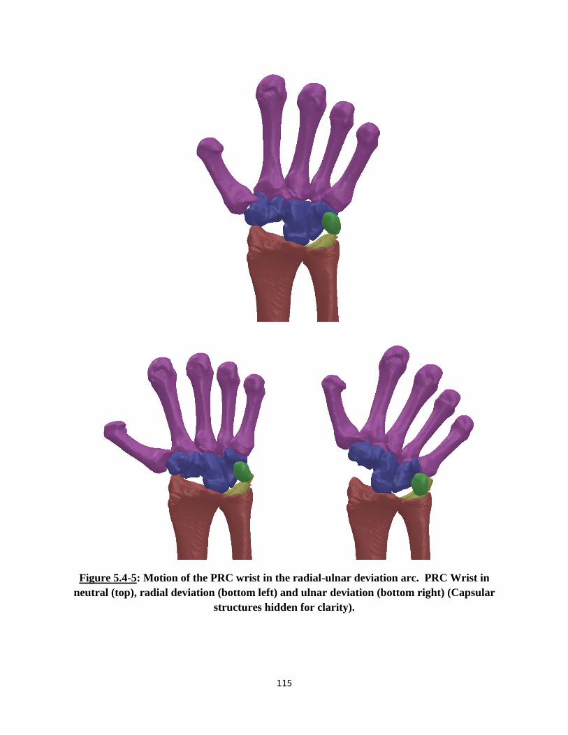
115
Figure 5.4-5: Motion of the PRC wrist in the radial-ulnar deviation arc. PRC Wrist in
neutral (top), radial deviation (bottom left) and ulnar deviation (bottom right) (Capsular
structures hidden for clarity).

116
In the experimental contact biomechanics study conducted by Tang et al, the
investigators determined contact pressure within the radiocarpal joint with the use of Fuji
pressure film. The study reported the changes in pressure and contact area between three
motions and two different wrist states. Within SolidWorks, no native feature exists that allows
for the calculation of pressure created between two interacting objects. However, SolidWorks is
able to calculate the contact force generated between solid bodies. This tool was utilized to
determine the contact forces generated between the various bones of interest and then compared
to the contact force calculated from the reported pressures and corresponding contact areas.
The 3D wrist model was used to replicate this study and the findings were compared to
the results from the cadaveric study (Figures 5.4-6 – 5.4-9). The results reported by the
cadaveric study included peak pressure and contact area values between the distal forearm
surface (distal radial surface, TFCC, and ulnar head) and the scaphoid and lunate for the intact
wrist and the capitate for the PRC wrist. These values from the study were used to calculate the
contact force experienced by the respective bones. It is not clear from the publication whether
additional contact between remaining carpal bones and the distal forearm surface was ignored or
if it was not reported. From the simulated studies, additional contact was found to occur in
various orientations especially in the PRC wrist. It was found that in certain positions, contact
occurred between the hamate and the TFCC as well as the trapezium and the distal radial surface.
In addition to that, standard deviation values were not reported and could not be calculated from
the data presented for the pressure results of the individual carpal bones.

117
Figure 5.4-6: Scaphoid Contact Forces at the Radiocarpal Joint in the Intact Wrist
For the intact wrist, the contact forces predicted by the 3D wrist model for the scaphoid
followed a relatively similar trend as the results from the experimental study (Figure 5.4-6). In
all three positions, the results demonstrated good correlation. In flexion the experimental study
reported a 63 N contact force, while the model predicted 67 N of force. In extension,
experimental 110 N was observed while the model predicted 114 N of force generation. And in
neutral, experimental 107 N of force was reported while the model predicted 98 N.
In the wrist, the lunate interacts with both the radial articulating surface as well as the
TFCC/ulna during joint motion. Thus, at the radio carpal joint, contact forces are generated from
two sources with the lunate. The experimental results reported for the lunate are a summation of
the forces generated from both sources. The 3D wrist model’s predicted results for the lunate
bone were not as comparable as that predicted for the scaphoid bone (Figure 5.4-7). However,
the overall decreasing trend in force generation when the wrist went from extension to flexion
0
20
40
60
80
100
120
Extension Neutral Flexion
Co
nta
ct F
orc
e (
N)
Cadaver Study Wrist Model
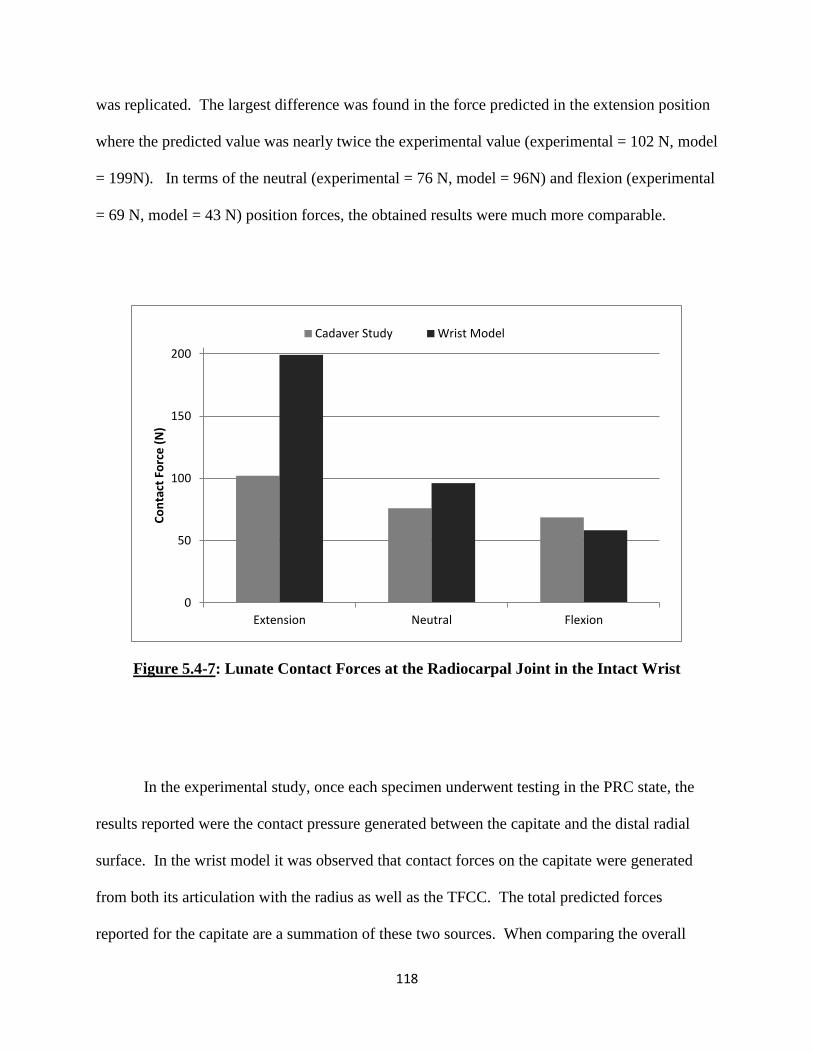
118
was replicated. The largest difference was found in the force predicted in the extension position
where the predicted value was nearly twice the experimental value (experimental = 102 N, model
= 199N). In terms of the neutral (experimental = 76 N, model = 96N) and flexion (experimental
= 69 N, model = 43 N) position forces, the obtained results were much more comparable.
Figure 5.4-7: Lunate Contact Forces at the Radiocarpal Joint in the Intact Wrist
In the experimental study, once each specimen underwent testing in the PRC state, the
results reported were the contact pressure generated between the capitate and the distal radial
surface. In the wrist model it was observed that contact forces on the capitate were generated
from both its articulation with the radius as well as the TFCC. The total predicted forces
reported for the capitate are a summation of these two sources. When comparing the overall
0
50
100
150
200
Extension Neutral Flexion
Co
nta
ct F
orc
e (
N)
Cadaver Study Wrist Model

119
predicted contact forces for the capitate bone (Figure 5.4-8), the general trend of the data
reported was found to be opposite of that of the experimental results. In the experimental results,
a slight increase in contact force was observed when the wrist goes from extension (155 N) to
neutral (167 N) to flexion (174 N). However, the wrist model predicted a much more rapid
decrease in contact force as the capitate moved from extension (197 N) to neutral (175 N) to
flexion (114 N). Even though the overall trend in change may be slightly off, the results
observed here does give an understanding of the range of forces the bones experience through its
motions. In addition to that, due to the lack of some information in the reported experimental
results, an extensive comparison between these values may not be appropriate.
Figure 5.4-8: Capitate Contact Forces at the Radiocarpal Joint in the PRC Wrist
Since the 3D wrist model predicted additional contact forces in carpal bones other than
just the scaphoid, lunate and capitate as reported by the experimental study, an additional
0
50
100
150
200
Extension Neutral Flexion
Co
nta
ct F
orc
e (
N)
Cadaver Study Wrist Model
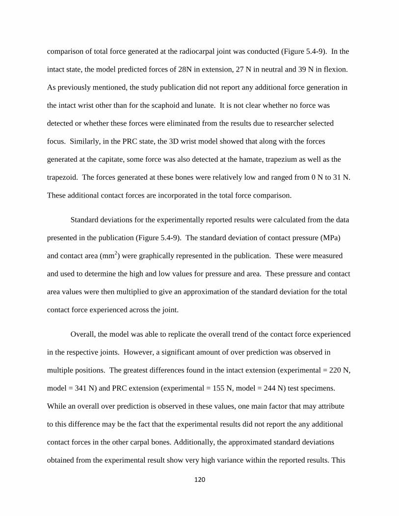
120
comparison of total force generated at the radiocarpal joint was conducted (Figure 5.4-9). In the
intact state, the model predicted forces of 28N in extension, 27 N in neutral and 39 N in flexion.
As previously mentioned, the study publication did not report any additional force generation in
the intact wrist other than for the scaphoid and lunate. It is not clear whether no force was
detected or whether these forces were eliminated from the results due to researcher selected
focus. Similarly, in the PRC state, the 3D wrist model showed that along with the forces
generated at the capitate, some force was also detected at the hamate, trapezium as well as the
trapezoid. The forces generated at these bones were relatively low and ranged from 0 N to 31 N.
These additional contact forces are incorporated in the total force comparison.
Standard deviations for the experimentally reported results were calculated from the data
presented in the publication (Figure 5.4-9). The standard deviation of contact pressure (MPa)
and contact area (mm2) were graphically represented in the publication. These were measured
and used to determine the high and low values for pressure and area. These pressure and contact
area values were then multiplied to give an approximation of the standard deviation for the total
contact force experienced across the joint.
Overall, the model was able to replicate the overall trend of the contact force experienced
in the respective joints. However, a significant amount of over prediction was observed in
multiple positions. The greatest differences found in the intact extension (experimental = 220 N,
model = 341 N) and PRC extension (experimental = 155 N, model = 244 N) test specimens.
While an overall over prediction is observed in these values, one main factor that may attribute
to this difference may be the fact that the experimental results did not report the any additional
contact forces in the other carpal bones. Additionally, the approximated standard deviations
obtained from the experimental result show very high variance within the reported results. This

121
high variance could also account for the differences observed between the experimental and
predicted results. It should be noted that most of the predicted values fell within the standard
deviation of the observed results. The percent difference between the model’s predicted results
and the experimentally reported values range from 17% for the flexion position in PRC to 57%
for the extension position in the PRC wrist (Table 5.4-1).
Figure 5.4-9: Total Contact Forces experienced by carpal bones at the Radiocarpal Joint
(Standard deviation approximated from publication)
0
50
100
150
200
250
300
350
Intact PRC Intact PRC Intact PRC
Extension Neutral Flexion
Co
nta
ct F
orc
e (
N)
Cadaver Study Wrist Model
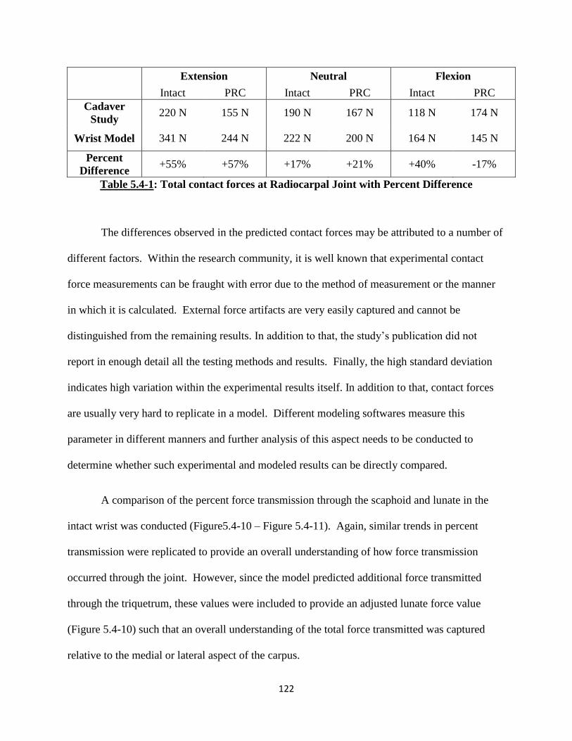
122
Extension Neutral Flexion
Intact PRC Intact PRC Intact PRC
Cadaver
Study 220 N 155 N 190 N 167 N 118 N 174 N
Wrist Model 341 N 244 N 222 N 200 N 164 N 145 N
Percent
Difference +55% +57% +17% +21% +40% -17%
Table 5.4-1: Total contact forces at Radiocarpal Joint with Percent Difference
The differences observed in the predicted contact forces may be attributed to a number of
different factors. Within the research community, it is well known that experimental contact
force measurements can be fraught with error due to the method of measurement or the manner
in which it is calculated. External force artifacts are very easily captured and cannot be
distinguished from the remaining results. In addition to that, the study’s publication did not
report in enough detail all the testing methods and results. Finally, the high standard deviation
indicates high variation within the experimental results itself. In addition to that, contact forces
are usually very hard to replicate in a model. Different modeling softwares measure this
parameter in different manners and further analysis of this aspect needs to be conducted to
determine whether such experimental and modeled results can be directly compared.
A comparison of the percent force transmission through the scaphoid and lunate in the
intact wrist was conducted (Figure5.4-10 – Figure 5.4-11). Again, similar trends in percent
transmission were replicated to provide an overall understanding of how force transmission
occurred through the joint. However, since the model predicted additional force transmitted
through the triquetrum, these values were included to provide an adjusted lunate force value
(Figure 5.4-10) such that an overall understanding of the total force transmitted was captured
relative to the medial or lateral aspect of the carpus.
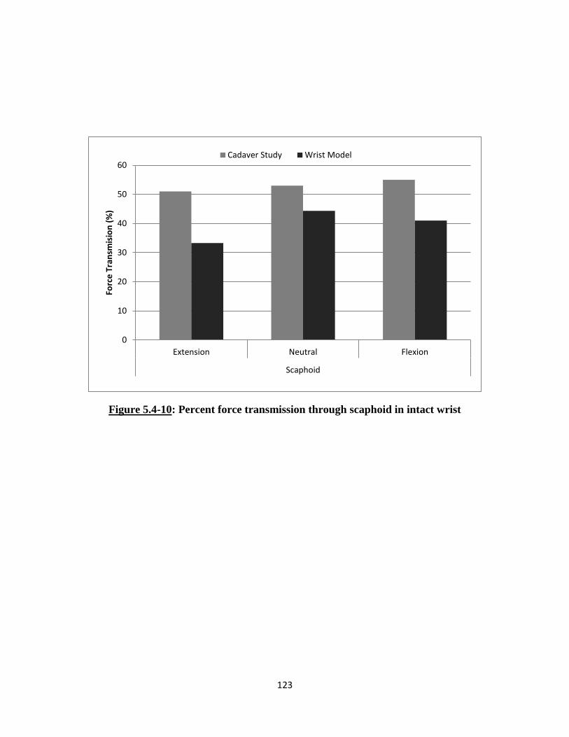
123
Figure 5.4-10: Percent force transmission through scaphoid in intact wrist
0
10
20
30
40
50
60
Extension Neutral Flexion
Scaphoid
Forc
e T
ran
smis
ion
(%
)
Cadaver Study Wrist Model
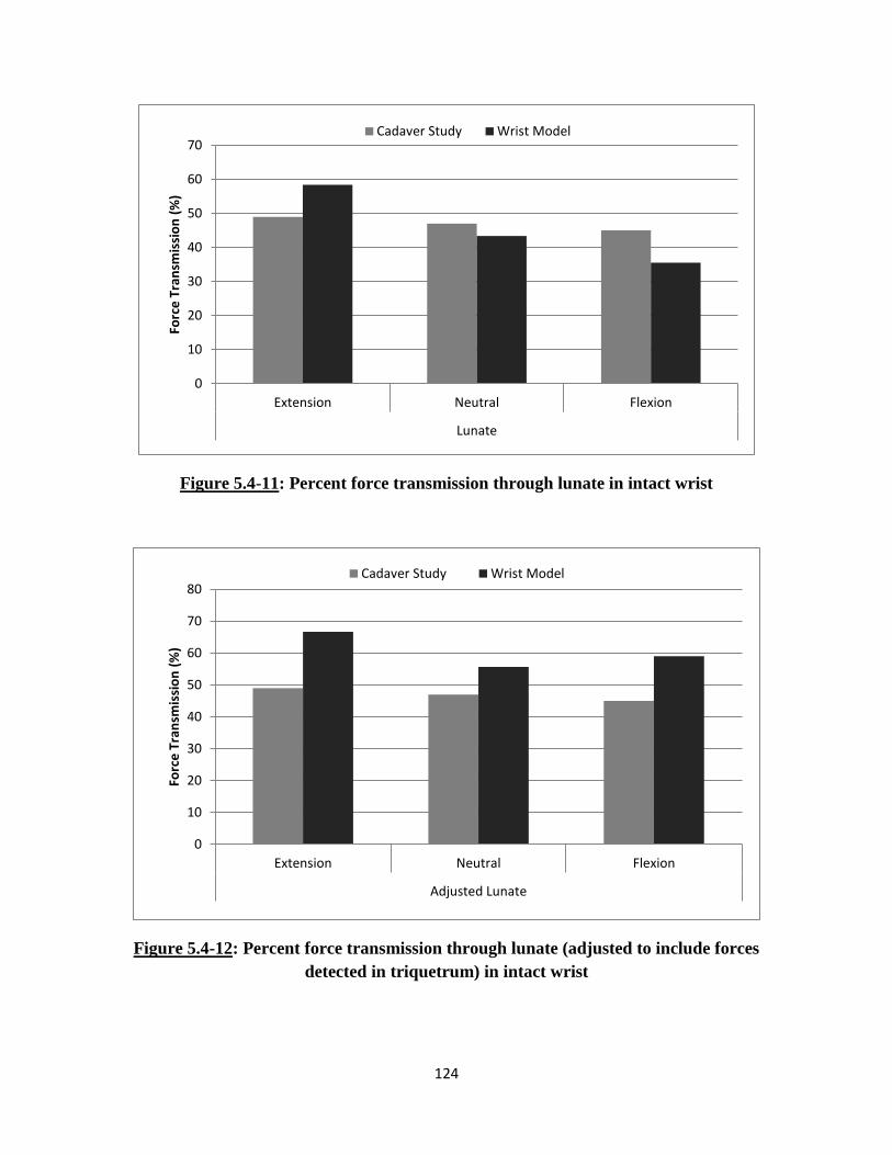
124
Figure 5.4-11: Percent force transmission through lunate in intact wrist
Figure 5.4-12: Percent force transmission through lunate (adjusted to include forces
detected in triquetrum) in intact wrist
0
10
20
30
40
50
60
70
Extension Neutral Flexion
Lunate
Forc
e T
ran
smis
sio
n (
%)
Cadaver Study Wrist Model
0
10
20
30
40
50
60
70
80
Extension Neutral Flexion
Adjusted Lunate
Forc
e T
ran
smis
sio
n (
%)
Cadaver Study Wrist Model

125
CHAPTER 6: DISCUSSION
Through the course of this thesis, a three-dimensional (3D) rigid body wrist model was
developed to accurately replicate the function and response of the human wrist joint. The 3D
wrist model was developed as described in Chapter 3 and validated against three different
cadaveric experimental studies discussed in Chapters 4 and 5. The experiments examined the
biomechanical changes observed in intact and surgically altered wrist joints. These studies were
replicated within SolidWorks and analyzed to demonstrate accuracy and its possible use as a
powerful predictive tool to determine wrist behavior.
The 3D wrist model developed during this work was based on the model developed by
Majors et al. For purpose of clarity during this discussion, the previous version of the wrist
model will be referred to as the Majors’ wrist model and the current version will be referred to as
the 3D wrist model. The method of modeling and representing the bones, ligaments and tendons
of the wrist were carried out in a very similar manner in both versions of the model. The method
of modeling for both these versions are unique compared with existing computational wrist joint
models reported within the literature. In the two computational wrist models, the function and
response of the joints were solely dependent on the 3D anatomy of the bony articular surfaces,
the ligaments and other soft tissue restraints and were directed by muscular forces or other
external perturbations. Accurate renditions of the bony articular surfaces were recreated within
the model design space to replicate the joint’s physiological range of motion. Joint motion was
not restricted to predefined paths or planes but instead responded in a geometry and restraint
based forward dynamic manner.

126
Majors’ wrist model replicated the right human hand while the 3D wrist model
represented the left human hand. Further, the 3D wrist model included additional soft tissue
structures, like the triangular fibrocartilage complex (TFCC) and capsular retinacular structures
that were not included in the previous version of the model. A detailed description of the method
of formulation and implementation of these additional soft tissue structures has been discussed in
Chapter 3.
The 3D wrist model was first validated against a cadaveric experimental study conducted
by Pervaiz et al which tested range of motion of the wrist joint in the normal state, and following
radioscapholunate (RSL) fusion, distal scaphoidectomy and triquetrectomy surgical procedures.
The Majors’ wrist model replicated this study in its entirety, with comparably good results. To
validate the 3D wrist model developed during the span of this work and to show reproducibility
of the results obtained between the two versions of the models, part of the RSL fusion
experimental study was simulated in the current version.
The 3D wrist model accurately replicated the trends observed during the experimental
study, functioned within physiologically reported ranges of joint motion and demonstrated
repeatability between the two versions of the computational model. In the intact state, the 3D
wrist model was able to accurately predict range of motion angles as reported by the cadaveric
study. For the four motions tested, there was less than 5 percent difference in the predicted
values for the modeled wrist and the values reported by the Majors’ model. All the predicted
results were also well within one standard deviation of the experimental study results. In the
Majors’ wrist model, while most of the angles obtained were well compared, some over
prediction was observed for ulnar deviation and flexion. In the 3D wrist model, more accurate
prediction capabilities were achieved. The over prediction in the original wrist model was
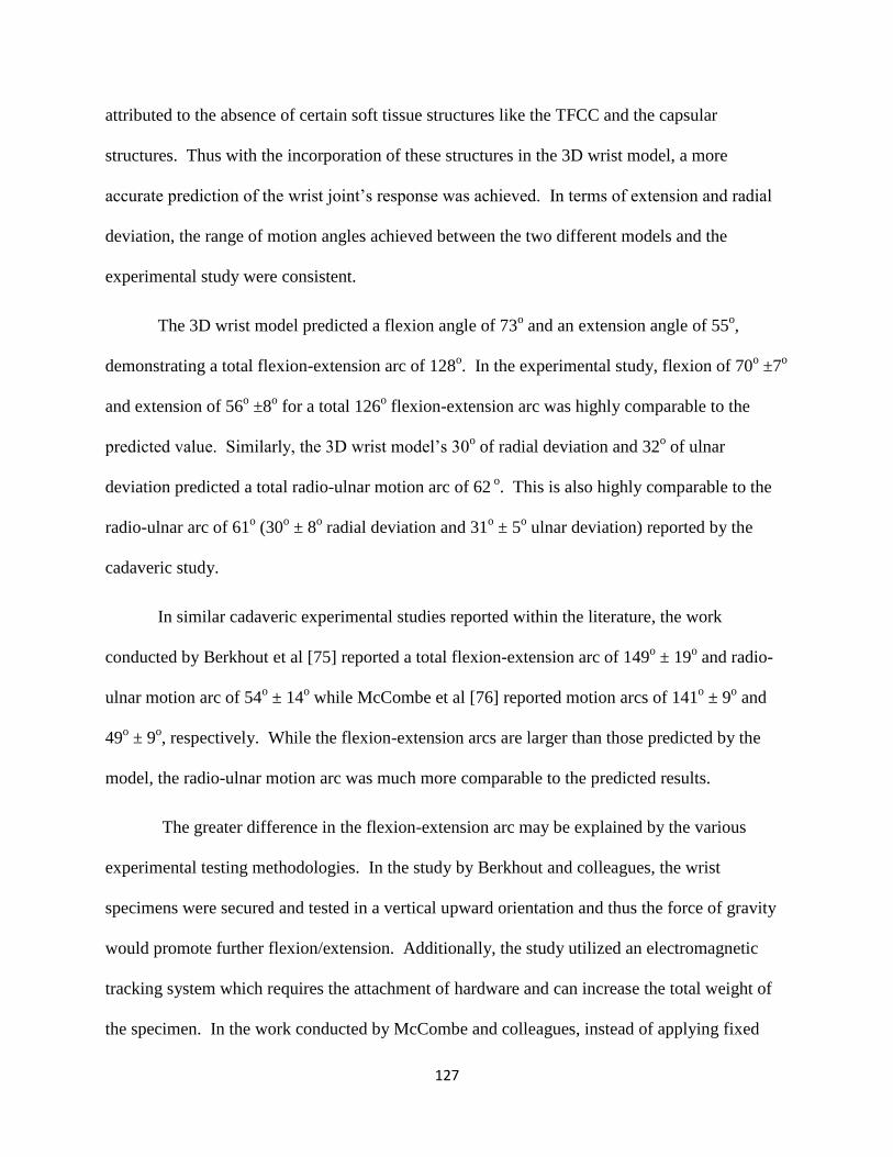
127
attributed to the absence of certain soft tissue structures like the TFCC and the capsular
structures. Thus with the incorporation of these structures in the 3D wrist model, a more
accurate prediction of the wrist joint’s response was achieved. In terms of extension and radial
deviation, the range of motion angles achieved between the two different models and the
experimental study were consistent.
The 3D wrist model predicted a flexion angle of 73o and an extension angle of 55
o,
demonstrating a total flexion-extension arc of 128o. In the experimental study, flexion of 70
o ±7
o
and extension of 56o ±8
o for a total 126
o flexion-extension arc was highly comparable to the
predicted value. Similarly, the 3D wrist model’s 30o of radial deviation and 32
o of ulnar
deviation predicted a total radio-ulnar motion arc of 62 o. This is also highly comparable to the
radio-ulnar arc of 61o (30
o ± 8
o radial deviation and 31
o ± 5
o ulnar deviation) reported by the
cadaveric study.
In similar cadaveric experimental studies reported within the literature, the work
conducted by Berkhout et al [75] reported a total flexion-extension arc of 149o ± 19
o and radio-
ulnar motion arc of 54o ± 14
o while McCombe et al [76] reported motion arcs of 141
o ± 9
o and
49o ± 9
o, respectively. While the flexion-extension arcs are larger than those predicted by the
model, the radio-ulnar motion arc was much more comparable to the predicted results.
The greater difference in the flexion-extension arc may be explained by the various
experimental testing methodologies. In the study by Berkhout and colleagues, the wrist
specimens were secured and tested in a vertical upward orientation and thus the force of gravity
would promote further flexion/extension. Additionally, the study utilized an electromagnetic
tracking system which requires the attachment of hardware and can increase the total weight of
the specimen. In the work conducted by McCombe and colleagues, instead of applying fixed
128
specified loads, each specimen was manually moved through the two motion arcs to the
approximate end-point of the range of motion. Finally, if the anatomical structure of the
radiocarpal joint is analyzed, the bony articular surface prevents motions in the radial and ulnar
aspect of the joint. On the other hand, motions in the palmar and dorsal aspect of the wrist are
not as restricted by bony articulations but rather controlled by soft tissue structures. Thus, the
flexion-extension arc is more likely dependent on the testing methodology and thus greater
differences are observed between the studies. This could also explain the consistency observed
in radio-ulnar motion arc between studies, even with different test methodologies.
The results obtained from the 3D wrist model with the simulated RSL fusion procedure
also resulted in consistent predictions as reported by the Majors’ wrist model. Further, the trends
of these predicted results correlated well with those observed in the experimental study.
However, the accuracy of the predicted angles did not improve as much as it did for the intact
normal wrist state. In the RSL fusion state, the 3D wrist model predicted a total flexion-
extension arc of 56o (flexion = 34
o, extension = 22
o) and radio-ulnar motion arc of 35
o (radial =
17o, ulnar = 18
o). By comparison, the experimental cadaver study reported a RSL flexion-
extension arc of 52o (flexion = 27
o ± 9
o, extension = 25
o ± 10
o) and radio-ulnar motion arc of 42
o
(radial = 20o ± 8
o, ulnar = 22
o ± 9
o). As expected, with the simulated fusion of the scaphoid and
the lunate bones, global wrist motion decreased significantly. While the 3D wrist model still
demonstrated predictions similar to those shown in the Majors’ wrist model, all results fell
within one standard deviation of the experimental study results. A comparison of the results of
the two different models showed some slight differences in motion angles, however this can be
attributed to anatomical differences and incorporation of additional soft tissue structures of the
wrist joint in the 3D wrist model.
129
While the cadaveric study and the Majors wrist model carried out additional experiments
in two further surgical states, these were not replicated in this work. The 3D wrist model’s
results demonstrate reproducibility between different models and its ability to accurately predict
human wrist motion. The addition of soft tissues like the TFCC and retinacular structures to the
current wrist model has greatly improved the accuracy of the results. However, lack of
representation of cartilage and other soft tissues that structurally may not be as well understood
by researchers at this time may contribute to some of the differences observed between the
model and cadaveric experiments.
Following validation of the 3D wrist model against the RSL fusion range of motion
study, the experimental study by Blankenhorn et al [33] was replicated. This cadaveric study
investigated the changes observed in the wrist joint following a proximal row carpectomy (PRC)
procedure. PRC is a motion preserving surgical procedure often employed to treat various
degenerative diseases of the wrist proximal carpal bones. PRC is favored by many practitioners
due to its ease of performance, lack of non-union formation and early patient recovery. [71], [77]
For the short term, the procedure has demonstrated positive results in preservation of wrist
motion and grip strength within functional ranges as well as providing pain relief. While there
have been concerns over the degenerative effects caused by the significant reduction of joint
articulation area, long term results have demonstrated dependability and durability without
significant functional deterioration of the articular surfaces. [72], [78]
The experimental protocol was replicated with the 3D wrist model as described in
Chapter 5 and separate simulations were performed for each test in the intact normal and
surgically altered PRC wrist. The results obtained from the model accurately replicated the
motion arcs as well as the changes observed due to PRC (Figure 5.4-1). When comparing the
130
percent decrease in motion between the intact and PRC wrist, it was found to be fairly accurate
for flexion (Model 32 % vs. Experimental 29% ± 2%) and comparable for both radial (Model 40
% vs. Experimental 45% ± 8%) and ulnar deviation (Model 22% vs. Experimental 15% ± 5%).
In extension, the model did under predict the percent change showing a 9% decrease in extension
following PRC, while the cadaveric study reported a total 36% ± 12%decrease. This difference
most likely arises from the method of representation of the soft tissues and the assumptions made
during the model’s development.
Once a human wrist joint undergoes a PRC procedure, most of the radiocarpal ligaments
lose at least one, if not both, skeletal attachment sites. However, these ligaments are not
removed from the wrist. While they may not provide their primary stabilizing role, most of these
ligaments are still integrated with the surrounding soft and capsular structures. These ligaments
continue to help maintain the integrity of these soft tissue structures and may even contribute to
their functional role. The only radiocarpal ligament that is left intact is the radiocapitate portion
of the RSC ligament. However, due to carpal height shortening, this lone palmar ligament was
no longer completely taut and could not provide complete support.
The tissue structure in which these radiocarpal ligaments most likely still play a
stabilizing role is within the wrist joint capsule. Anatomically, the ligaments integrate and are
confluent throughout the tissue. Thus, healthy ligaments not only play their primary role of
stabilizing between their two attachments sites, but also support in a three dimensional manner
via the capsule. Even with the elimination of an attachment site, the ligament still can contribute
to the overall network that surrounds the carpus.
131
A PRC procedure is normally conducted through a dorsal excision of the wrist. Upon
careful bone extraction, an anatomical repair of the extensor reticulum (ER) is carried out. The
dorsal capsule is then overlapped and sutured following which the remaining tissue and skin is
sutured closed. [79–81] Since a PRC procedure has shown long term positive functional effects
[72], [78], [81] without many of ligaments performing their primary stabilizing role, it can be
assumed that the surrounding soft tissue structures enhance their support to the deficient wrist.
As described in Chapter 2, the FR and ER are bands that span the palmar and dorsal aspect of the
wrist securing most of the wrist and finger muscle tendons and maintaining their anatomically
correct lines of action. Testing with the 3D wrist model demonstrated that these capsular
retinacular structures were essential in maintaining proper function of the wrist joint, especially
in a surgically altered state. However, the role played by the modeled capsular structures are
most likely functions performed by not only the FR and ER but also the wrist joint capsule and a
combination of other soft tissue structures within the region. Currently, the biomechanical role
of all these surrounding soft tissue structures in relation to the carpus is not well understood. In
terms of the FR and ER, testing on the joint has demonstrated increased tendon excursion,
bowstringing and changes in muscular anatomical lines of action upon excision of these
structures. [31], [62] Additional investigations will be required to better understand how this
group of soft tissue structures directly affect carpal bone kinematics.
In the clinical study conducted by Cohen et al, [71] an average 62% ± 10% preservation
of the flexion –extension arc and 51% ± 18% of the radial-ulnar motion arc was reported after a
PRC procedure. Likewise, in the study by Wyrick et al which treated eleven wrist joints with a
PRC procedure, [77] the average wrist motion angles were measured to be 85o for the flexion-
extension arc and 31o for radial-ulnar motion arc. Overall, the study reported a total 64%

132
(average of all four motions) retention of the wrist motion arc relative to the contralateral healthy
wrist. In the clinical study with a minimum ten year follow-up conducted by Jebson et al, [78]
the average flexion-extension arc was reported as 84o pre-op and 77
o post-op and the average
radial-ulnar motion arc was 39o pre-op and 34
o post-op. The total average range of motion arc
was found to be 63% of the contralateral wrist. In another long term follow-up clinical study
conducted by DiDonna et al, [72] post-operatively the flexion-extension arc was 72o and the
radial-ulnar motion arc was 40o, a 61% preservation of the total wrist motion arc. With respect
to the computationally predicted results, the 3D wrist model demonstrated a total 74% retention
of the total intact healthy wrist motion arc post-operatively.
While the 3D wrist model’s predicted value was slightly higher than the clinically
reported values, the difference is most likely due to the fact that after a surgical procedure, the
patient’s tissue undergoes healing and may even form scar tissue. The healed and scar tissue
would most likely provide additional restrictions and support to the carpal bones. This would
lead to a reduced motion arc experienced by the joint. Additionally, clinical studies reported
very small post-operative radial deviation angles such as 4o,[77] 7
o,[71] and 9
o [72]. These
small angles were most likely caused by radial styloid impingement with the trapezium. No
significant impingement was observed in the 3D wrist model and hence it resulted in a 15o radial
deviation prediction. This difference would also account for the greater motion arc preservation
predicted by the 3D wrist model. Since the Blankenhorn experimental study utilized cadaveric
specimens which could not undergo healing, the observed 69% ± 17% total motion arc
preservation post-operatively is much more comparable to the total percent preservation
predicted by the 3D wrist model.

133
The final study the 3D wrist model was validated against was the cadaveric study
conducted by Tang et al. [34] This experiment investigated the changes in contact biomechanics
within the bones across the radiocarpal joint following a PRC procedure. The methodology of
the study was replicated within SolidWorks as described in Chapter 5. While the general model
used for this study was identical to the models used to replicate the previous two experiments,
certain features were suppressed to allow accurate physiological simulation. The capsular
retinacular structures were included within the model to provide additional stability to the wrist
model during kinematic motion in the PRC state. However, due to the nature of this final test, all
four of the retinacular structures had to be suppressed to allow for accurate physiological
simulation.
In the human wrist joint, the FR and ER wrap around the carpal bones and other soft
tissue structures cupping and imparting a stabilizing force on the structures it encapsulates. The
capsular structures were modeled to replicate this function of the FR and ER. They were
represented as four solid bodies (two on the palmar aspect and two on the dorsal aspect) tethered
to each other and the radial and ulnar styloid process. During modeled wrist motion, the carpal
bone structures generate contact force against these solid bodies which in turn interact with the
radius and ulna. Thus, in the complete model, contact force transmission occurred through an
anatomically incorrect pathway. Any contact pressure results obtained from the model in this
state would not be comparable to the results observed in an experimental study. However, upon
suppression of the solid body retinacular structures, the PRC wrist was found to be too unstable
to accurately replicate any biomechanical analysis. Thus to replicate the experimental test
methodology employed by Tang et al, a multistep approach was utilized. First the complete
wrist model was used to determine the desired testing positions of the joint. Then the joints were

134
secured in the desired positions with the incorporation of additional restrictions and reference
planes (described in detail in Chapter 5). The solid body capsular structures and distal TFCC
were then removed from the design space to reduce the amount of artifact contact force within
the system. In this manner, the 3D wrist model was able to determine the contact force
transmission through the carpus replicating the cadaveric contact pressure test.
Comparing the results predicted by the 3D wrist model with the experimental results, the
overall trend in changes observed in total contact force generation was replicated. When looking
at the total contact force measured, there was some significant over prediction in extension for
both the intact and PRC wrist (Figure 5.4-9). However, when looking at the percent change in
force pre- and post-operatively, the greatest difference was found in the flexion position. Percent
changes in bone contact forces predicted by the 3D wrist model were as follows: in extension a
28% decrease (experimental = 30% decrease), in neutral a 10% decrease (experimental = 12%
decrease), and in flexion a 9% decrease (experimental = 47% increase). Thus, when looking at
percent change between the two wrist states, while the results are fairly accurate for both
extension and neutral, the flexed wrist experiences a dramatically different response than
predicted. It can also be noted that with the exception of the intact wrist in flexion and
extension, all the results fall within one standard deviation of the experimentally reported results.
When analyzing the predicted force generated between the individual carpal bones (Figure 5.4-6
– Figure 5.4-8), while the scaphoid and lunate predictions follow the experimental observed
trends, the capitate appears to respond experimentally in the PRC state in a different manner than
as replicated in the model.
The differences in the contact forces observed can be attributed to a number of different
factors. In the experimental study, Fuji pressure film was placed within the radiocarpal joint to

135
measure the pressure generated between the carpal bones and the radial articulating surface,
TFCC and ulna. However, the study only reports contact pressure generated by the scaphoid and
lunate in the intact wrist and the capitate of the PRC wrist. The study does not explain if no
additional contact was detected at the radioulnar articulating surface or if the additional pressures
were disregarded from the results. An example image of the Fuji UltraSuperLow film included
in the publication does indicate that additional pressures were detected by bones other than just
the scaphoid and lunate. However, this fact is not noted or discussed within the text of the
publication.
When the study was replicated with the 3D wrist model, the triquetrum was found to bear
some force in all three states in the intact wrist. In the PRC wrist, the hamate was found to
experience contact force across the radiocarpal joint. The trapezium and the trapezoid were also
found to interact with the radius in certain positions in the PRC wrist. If these additional bony
contact forces were ignored by the experimental study, this could account for the general over
prediction found with the 3D wrist model.
Experimentally measuring the contact forces generated between bones can be difficult
and lead to inaccurate results. While one of the most common methods of measuring contact
pressure is with Fuji pressure film, these tend be extremely sensitive and can easily form
artifacts. [34] Even after extreme care is taken with a complex joint such as the wrist joint, it
most likely undergoes unnatural motions until an equilibrium is reached upon application of
tendon forces. These motions would express inaccurate results on the pressure film. This fact
could also be noted by the very high standard deviations observed in the experimental results
(Figure 5.4-9). Additionally, since the test with each specimen was repeated until three constant

136
pressure films were obtained, the constant distraction of the carpus may also lead to damage and
changes resulting anatomically incorrect responses.
Finally, the differences between the model’s predicted and experimental results may also
be caused by the method utilized for replicating the study. In the experimental study, each
position was achieved by loading the tendons with a combined total load of 200N. During the
experimental test, the wrist position was manually maintained to prevent out of plane motion.
However, the study does not specify how the wrist position was maintained. In the 3D wrist
model, constant wrist position was maintained during tests with artificial planes to secure the
joint at the desired angles. Since the wrist joint was repositioned to the desired starting positions,
the starting point for most of the soft tissue structures were not in its natural resting length.
Thus, time was provided prior to application of loads to allow the carpal bones to reach
equilibrium at the manually achieved wrist position. Since the simulation starting point for the
model was at a set wrist angle instead of neutral, the carpal bones may have responded
differently and attained an anatomically different equilibrium state than that achieved by moving
the wrist from neutral to the defined joint angle.
The experimental publication did not explain the specific tendon loads applied during the
study. While it defined that a total combined load of 200N was applied to tendons, the specific
break up between the tendons was not provided. Additionally, it was unclear whether equal
loads were applied in each position pre- and post-op. For the purposes of replicating the
experiment, this was assumed to be the case. The specific loads applied to each tendon were
selected to reflect the ratio of load applied during the kinematic Range of Motion PRC study.
Due to the lack of specific information, this method was determined to be the most logical means
137
of selecting the tendon loads. Variations in individual tendon load would play a large role in
some of the differences observed between the experimental and predicted results.
During the incorporation of the additional soft tissue structures within the 3D wrist
model, a number of assumptions and simplifications were made. The TFCC was modeled as a
two part structure, each of which was represented as a solid body structure. In actuality, the
TFCC is a soft tissue structure which probably experiences significant deformation during wrist
motion. However, to replicate the functionality that was desired, the solid body assumption was
required. Similarly, to recreate the wrapping stabilizing effect of the capsular retinacular
structures, a similar assumption was also required. Currently, it is not definitively clear from the
literature whether these two groups of tissue play the role that has been assumed within this
model. While the model does indicate that these tissues play a major stabilizing role, especially
in the deficient wrist, more research will be needed to validate these assumptions.
Additionally, the manner in which the capsular structures are discussed in this text, it is
referred to as primarily the flexor and extensor retinaculum. However the functional wrapping
stabilizing role discussed is most likely performed by the combination of the retinacular
structures, the wrist joint capsule and other surrounding soft tissue structures. Thus, simply
associating the modeled capsular bodies as the FR and ER may not be appropriate. Instead, it is
more likely that the capsular bodies incorporated in the 3D wrist model represented the
combined function of the FR, ER and the wrist joint capsule.
The 3D wrist model was able to replicate and predict the biomechanical response of the
joint following different surgical procedures. It also provided some insight into the functions of
the various structures the form the overall joint. The TFCC is a not a well understood tissue

138
structure. Comparing the motions predicted by the Majors wrist model and the current 3D wrist
model, it would indicate that the TFCC does play a major stabilizing role on the ulnar aspect of
the wrist. Additionally, when a PRC procedure was replicated on the 3D wrist model, the model
failed to come to a solution when the TFCC structures were not included. This was due to lack
of ulnar side support and rapid and unstable response of the carpus during this motion. Since the
TFCC was a critical aspect in stabilizing the surgically altered wrist, this may indicate that this
soft tissue structure plays a much more critical role than currently understood.
A similar observation was made in terms of the capsular retinacular structures. These
modeled structures were essential in stabilizing the surgically altered PRC wrist to allow the
model to determine a solution. They prevented unnatural wrist joint motion. These modeled
structures not only replicated the FR and ER, but also all the muscle tendons, ligaments and other
tissue that is compacted around the wrist joint. While a good functional understanding on the
stabilizing role this group of tissue cannot be found within the literature, the results observed
from this work does indicate that it is significant and may justify further investigations.
139
CHAPTER 7: CONCLUSION
The 3D wrist model was designed to accurately replicate the skeletal and soft tissue
anatomy of the human wrist joint. Motion was dictated solely by the articular surfaces and the
restraints provided by ligaments and other soft tissue structures. Muscular force was replicated
in an anatomically correct orientation. Some assumptions were required to model the function
and role played in stabilization by the TFCC and retinacular structures. The material properties
of the ligaments and soft tissues incorporated within the model were based on experimentally
measured values which were reported within the literature. Overall, the model was designed to
respond to perturbations in a forward dynamic manner: based on articular geometry and the
defined constraints.
The model was validated against three experimental cadaveric studies which performed
two different surgical procedures of the wrist. Both these procedures are often performed by
practitioners to treat various injuries and pathologies of the joint. Overall, the results predicted
by the model showed good correlation to experimentally reported results. As a RBM wrist
model, it demonstrated excellent accuracy in predicting the global kinematic response of the joint
pre- and post-operation. It also provided the ability to measure other parameters that normally
would not be possible in a live or cadaveric specimen. The contact force results from the model
did not demonstrate very high accuracy as compared to the cadaveric study results. However,
these parameters are very difficult to measure experimentally and researchers require more
efficient tools and a better understanding of the parameter. The model is able to provide some
insight and understanding in carpal contact force changes. These values may be advantageous to

140
surgeons in understanding the effects of corrective procedures on individual components of the
joint.
The model has also provided some deep insight into tissue structures that are not well
understood by investigators. Tissue structures such as the TFCC and the capsular retinacular
structures require further research and experimentation to obtain a deep understanding of their
role in wrist joint function. This model has demonstrated the importance of these structures,
especially in a deficient and weakened wrist.
While the model did demonstrate high accuracy in terms of predicting the kinematic
response in the cadaveric specimens, the model will require more development prior to it
becoming a readily used biomechanical investigation tool. First, further work will be required to
validate some of the assumptions made during the development of the model. In addition to that,
further validation against population data may be required to determine true outcomes of the
joint. Additionally, sensitivity studies may also be useful to determine effects of component
level differences on the overall joint response.
With further development, the 3D wrist model could be used as a predictive tool to
determine the response of the joint prior to a surgical intervention. Individualized models could
be formulated using high resolution scans of a patient’s appendage which would allow to account
for structural and anatomical variations. While further work needs to be performed to overcome
some of the assumptions made during its development, the 3D wrist model is a powerful tool that
is capable of allowing us to better understand healthy joints, degenerative changes and help plan
for corrective interventions.
141
LITERATURE CITED
[1] S. D. Carrigan, R. A. Whiteside, D. R. Pichora, and C. F. Small, “Development of a three-
dimensional finite element model for carpal load transmission in a static neutral posture,”
Ann Biomed Eng, vol. 31, no. 6, pp. 718–725, Jun. 2003.
[2] M. K. Gíslason, B. Stansfield, and D. H. Nash, “Finite element model creation and stability
considerations of complex biological articulation: The human wrist joint,” Med Eng Phys,
vol. 32, no. 5, pp. 523–531, Jun. 2010.
[3] P. Ledoux, D. Lamblin, A. Wuilbaut, and F. Schuind, “A finite-element analysis of
Kienbock’s disease,” J Hand Surg Eur Vol, vol. 33, no. 3, pp. 286–291, Jun. 2008.
[4] M. K. Gislason, D. H. Nash, A. Nicol, A. Kanellopoulos, M. Bransby-Zachary, T. Hems, B.
Condon, and B. Stansfield, “A three-dimensional finite element model of maximal grip
loading in the human wrist,” Proc Inst Mech Eng H, vol. 223, no. 7, pp. 849–861, Oct.
2009.
[5] D. D. Anderson, B. R. Deshpande, T. E. Daniel, and M. E. Baratz, “A three-dimensional
finite element model of the radiocarpal joint: distal radius fracture step-off and stress
transfer,” Iowa Orthop J, vol. 25, pp. 108–117, 2005.
[6] S. Boutroy, B. Van Rietbergen, E. Sornay-Rendu, F. Munoz, M. L. Bouxsein, and P. D.
Delmas, “Finite element analysis based on in vivo HR-pQCT images of the distal radius is
associated with wrist fracture in postmenopausal women,” J. Bone Miner. Res., vol. 23, no.
3, pp. 392–399, Mar. 2008.
[7] M. N. Bajuri, M. R. A. Kadir, M. M. Raman, and T. Kamarul, “Mechanical and functional
assessment of the wrist affected by rheumatoid arthritis: A finite element analysis,” Medical
engineering & physics, Jan. 2012.
[8] P. Ledoux, D. Lamblin, and R. Targowski, “Modifications to the mechanical behavior of
the wrist after fracture of the scaphoid. Modeling by finite element analysis,” Acta
Orthopaedica Belgica, vol. 67, no. 3, pp. 236–241, 2001.
[9] W. B. Edwards and K. L. Troy, “Simulating distal radius fracture strength using
biomechanical tests: a modeling study examining the influence of boundary conditions,” J
Biomech Eng, vol. 133, no. 11, p. 114501, Nov. 2011.
[10] E. Horii, M. Garcia-Elias, A. T. Bishop, W. P. Cooney, R. L. Linscheid, and E. Y. Chao,
“Effect on force transmission across the carpus in procedures used to treat Kienböck’s
disease,” J Hand Surg Am, vol. 15, no. 3, pp. 393–400, May 1990.
[11] X. Guo, Y. Fan, and Z.-M. Li, “Effects of dividing the transverse carpal ligament on the
mechanical behavior of the carpal bones under axial compressive load: a finite element
study,” Med Eng Phys, vol. 31, no. 2, pp. 188–194, Mar. 2009.
142
[12] Y. C. Fung, First Course in Continuum Mechanics, 3rd ed. Prentice Hall, 1993.
[13] I. W. Charlton and G. R. Johnson, “Application of spherical and cylindrical wrapping
algorithms in a musculoskeletal model of the upper limb,” J Biomech, vol. 34, no. 9, pp.
1209–1216, Sep. 2001.
[14] F. C. van der Helm, “Analysis of the kinematic and dynamic behavior of the shoulder
mechanism,” J Biomech, vol. 27, no. 5, pp. 527–550, May 1994.
[15] T. M. Barker, C. Kirtley, and J. Ratanapinunchai, “Calculation of multi-segment rigid body
joint dynamics using MATLAB,” Proc Inst Mech Eng H, vol. 211, no. 6, pp. 483–487,
1997.
[16] J. Wismans, F. Veldpaus, J. Janssen, A. Huson, and P. Struben, “A three-dimensional
mathematical model of the knee-joint,” J Biomech, vol. 13, no. 8, pp. 677–685, 1980.
[17] S. D. Kwak, L. Blankevoort, and G. A. Ateshian, “A Mathematical Formulation for 3D
Quasi-Static Multibody Models of Diarthrodial Joints,” Comput Methods Biomech Biomed
Engin, vol. 3, no. 1, pp. 41–64, 2000.
[18] F. Schuind, W. P. Cooney, R. L. Linscheid, K. N. An, and E. Y. Chao, “Force and pressure
transmission through the normal wrist. A theoretical two-dimensional study in the
posteroanterior plane,” J Biomech, vol. 28, no. 5, pp. 587–601, May 1995.
[19] K. Manal, X. Lu, M. K. Nieuwenhuis, P. J. M. Helders, and T. S. Buchanan, “Force
transmission through the juvenile idiopathic arthritic wrist: a novel approach using a sliding
rigid body spring model,” J Biomech, vol. 35, no. 1, pp. 125–133, Jan. 2002.
[20] N. Iwasaki, E. Genda, P. J. Barrance, A. Minami, K. Kaneda, and E. Y. Chao,
“Biomechanical analysis of limited intercarpal fusion for the treatment of Kienböck’s
disease: a three-dimensional theoretical study,” J. Orthop. Res., vol. 16, no. 2, pp. 256–263,
Mar. 1998.
[21] E. Genda and E. Horii, “Theoretical stress analysis in wrist joint--neutral position and
functional position,” J Hand Surg Br, vol. 25, no. 3, pp. 292–295, Jun. 2000.
[22] M. Majima, E. Horii, H. Matsuki, H. Hirata, and E. Genda, “Load transmission through the
wrist in the extended position,” J Hand Surg Am, vol. 33, no. 2, pp. 182–188, Feb. 2008.
[23] H. Matsuki, E. Horii, M. Majima, E. Genda, S. Koh, and H. Hirata, “Scaphoid nonunion
and distal fragment resection: analysis with three-dimensional rigid body spring model,”
Journal of Orthopaedic Science, vol. 14, no. 2, pp. 144–149, Apr. 2009.
[24] S. Fischli, R. Sellens, M. Beek, and D. Pichora, “Simulation of extension, radial and ulnar
deviation of the wrist with a rigid body spring model,” Journal of Biomechanics, vol. 42,
no. 9, pp. 1363–1366, 2009.

143
[25] M. Kobayashi, R. A. Berger, L. Nagy, R. L. Linscheid, S. Uchiyama, M. Ritt, and K. N.
An, “Normal kinematics of carpal bones: a three-dimensional analysis of carpal bone
motion relative to the radius,” Journal of Biomechanics, vol. 30, no. 8, pp. 787–793, 1997.
[26] M. Nanno, W. L. Buford Jr, R. M. Patterson, C. R. Andersen, and S. F. Viegas, “Three-
dimensional analysis of the ligamentous attachments of the second through fifth
carpometacarpal joints,” Clin Anat, vol. 20, no. 5, pp. 530–544, Jul. 2007.
[27] T. M. Moojen, J. G. Snel, M. J. Ritt, H. W. Venema, G. J. den Heeten, and K. E. Bos,
“Pisiform kinematics in vivo,” J Hand Surg Am, vol. 26, no. 5, pp. 901–907, Sep. 2001.
[28] T. Pevny, G. M. Rayan, and D. Egle, “Ligamentous and tendinous support of the pisiform,
anatomic and biomechanical study,” J Hand Surg Am, vol. 20, no. 2, pp. 299–304, Mar.
1995.
[29] R. A. Berger, “The ligaments of the wrist. A current overview of anatomy with
considerations of their potential functions,” Hand Clin, vol. 13, no. 1, pp. 63–82, Feb. 1997.
[30] B. J. Majors and J. S. Wayne, “Development and validation of a computational model for
investigation of wrist biomechanics,” Ann Biomed Eng, vol. 39, no. 11, pp. 2807–2815,
Nov. 2011.
[31] A. K. Palmer, J. R. Skahen, F. W. Werner, and R. R. Glisson, “The extensor retinaculum of
the wrist: an anatomical and biomechanical study,” J Hand Surg Br, vol. 10, no. 1, pp. 11–
16, Feb. 1985.
[32] K. Pervaiz, W. H. Bowers, J. E. Isaacs, J. R. Owen, and J. S. Wayne, “Range of motion
effects of distal pole scaphoid excision and triquetral excision after radioscapholunate
fusion: a cadaver study,” J Hand Surg Am, vol. 34, no. 5, pp. 832–837, Jun. 2009.
[33] B. D. Blankenhorn, H. J. Pfaeffle, P. Tang, D. Robertson, J. Imbriglia, and R. J. Goitz,
“Carpal kinematics after proximal row carpectomy,” J Hand Surg Am, vol. 32, no. 1, pp.
37–46, Jan. 2007.
[34] P. Tang, J. Gauvin, M. Muriuki, J. H. Pfaeffle, J. E. Imbriglia, and R. J. Goitz,
“Comparison of the ‘contact biomechanics’ of the intact and proximal row carpectomy
wrist,” J Hand Surg Am, vol. 34, no. 4, pp. 660–670, Apr. 2009.
[35] P. K. Levangie and C. C. Norkin, Joint Structure and Function : A Comprehensive
Analysis, 5th ed.. Philadelphia: FADavis Co, 2011.
[36] R. A. Berger, “The anatomy of the ligaments of the wrist and distal radioulnar joints,” Clin.
Orthop. Relat. Res., no. 383, pp. 32–40, Feb. 2001.
[37] K. N. An, R. A. Berger, and W. P. Cooney, Biomechanics of the Wrist Joint. New York:
Springer-Verlag, 1991.

144
[38] W. P. Cooney, J. H. Dobyns, and R. L. Li, The Wrist: Diagnosis and Operative Treatment,
1st Edition. Mosby, 1998.
[39] F. Schuind, K. N. An, L. Berglund, R. Rey, W. P. Cooney 3rd, R. L. Linscheid, and E. Y.
Chao, “The distal radioulnar ligaments: a biomechanical study,” J Hand Surg Am, vol. 16,
no. 6, pp. 1106–1114, Nov. 1991.
[40] A. K. Palmer and F. W. Werner, “The triangular fibrocartilage complex of the wrist--
anatomy and function,” J Hand Surg Am, vol. 6, no. 2, pp. 153–162, Mar. 1981.
[41] S. S. Salman and M. Ullah, “The attachments of the lateral and medial ends of the extensor
retinaculum of the human wrist,” Acta Anat (Basel), vol. 122, no. 3, pp. 185–186, 1985.
[42] S. E. Logan and M. D. Nowak, “Intrinsic and extrinsic wrist ligaments: biomechanical and
functional differences,” ISA Trans, vol. 27, no. 3, pp. 37–41, 1988.
[43] J. K. Mayfield, R. Johnson, and R. Kilcoyne, “The ligaments of the human wrist and their
functional significance,” The Anatomical Record, vol. 186, no. 3, pp. 417–428, 1976.
[44] J. Taleisnik, “The ligaments of the wrist,” J Hand Surg Am, vol. 1, no. 2, pp. 110–118, Sep.
1976.
[45] G. A. Buijze, S. A. Lozano-Calderon, S. D. Strackee, L. Blankevoort, and J. B. Jupiter,
“Osseous and Ligamentous Scaphoid Anatomy: Part I. A Systematic Literature Review
Highlighting Controversies,” The Journal of Hand Surgery, vol. 36, no. 12, pp. 1926–1935,
Dec. 2011.
[46] M. D. Nowalk and S. E. Logan, “Distinguishing biomechanical properties of intrinsic and
extrinsic human wrist ligaments,” J Biomech Eng, vol. 113, no. 1, pp. 85–93, Feb. 1991.
[47] R. A. Berger and W. F. Blair, “The radioscapholunate ligament: a gross and histologic
description,” Anat. Rec., vol. 210, no. 2, pp. 393–405, Oct. 1984.
[48] J. K. Mayfield and W. J. Williams, “Biomechanical properties of human carpal ligaments,”
Orthopaedic Research Society, pp. 143 – 144.
[49] S. F. Viegas, S. Yamaguchi, N. L. Boyd, and R. M. Patterson, “The dorsal ligaments of the
wrist: anatomy, mechanical properties, and function,” J Hand Surg Am, vol. 24, no. 3, pp.
456–468, May 1999.
[50] M. Benjamin, E. J. Evans, and D. J. Pemberton, “Histological studies on the triangular
fibrocartilage complex of the wrist,” J. Anat., vol. 172, pp. 59–67, Oct. 1990.
[51] H. J. Chiou, C. Y. Chang, Y. H. Chou, C. C. Hsu, Y. F. Jim, C. M. Tiu, and M. M. Teng,
“Triangular fibrocartilage of wrist: presentation on high resolution ultrasonography,” J
Ultrasound Med, vol. 17, no. 1, pp. 41–48, Jan. 1998.

145
[52] R. L. Linscheid, “Biomechanics of the distal radioulnar joint,” Clin. Orthop. Relat. Res., no.
275, pp. 46–55, Feb. 1992.
[53] R. A. Berger and A. C. Weiss, Hand Surgery, 1st Edition. Philadelphia: Lippincott
Williams & Wilkins, 2004.
[54] A. C. Rettig, “Athletic Injuries of the Wrist and Hand Part I: Traumatic Injuries of the
Wrist,” Am J Sports Med, vol. 31, no. 6, pp. 1038–1048, Nov. 2003.
[55] J. B. Tang, J. Ryu, and V. Kish, “The triangular fibrocartilage complex: An important
component of the pulley for the ulnar wrist extensor*,” The Journal of Hand Surgery, vol.
23, no. 6, pp. 986–991, 1998.
[56] F. Netter, Atlas of Human Anatomy, Professional Edition, 5th Edition. Saunders, 2010.
[57] R. O. Nigro, “Anatomy of the flexor retinaculum of the wrist and the flexor carpi radialis
tunnel,” Hand Clin, vol. 17, no. 1, pp. 61–64, vi, Feb. 2001.
[58] C. Stecco, V. Macchi, L. Lancerotto, C. Tiengo, A. Porzionato, and R. De Caro,
“Comparison of transverse carpal ligament and flexor retinaculum terminology for the
wrist,” J Hand Surg Am, vol. 35, no. 5, pp. 746–753, May 2010.
[59] T. K. Cobb, B. K. Dalley, R. H. Posteraro, and R. C. Lewis, “Anatomy of the flexor
retinaculum,” J Hand Surg Am, vol. 18, no. 1, pp. 91–99, Jan. 1993.
[60] J. Taleisnik, R. H. Gelberman, B. W. Miller, and R. M. Szabo, “The extensor retinaculum
of the wrist,” J Hand Surg Am, vol. 9, no. 4, pp. 495–501, Jul. 1984.
[61] M. Garcia-Elias, K. N. An, W. P. Cooney 3rd, R. L. Linscheid, and E. Y. Chao, “Stability
of the transverse carpal arch: an experimental study,” J Hand Surg Am, vol. 14, no. 2 Pt 1,
pp. 277–282, Mar. 1989.
[62] F. K. Fuss and T. F. Wagner, “Biomechanical alterations in the carpal arch and hand
muscles after carpal tunnel release: A further approach toward understanding the function
of the flexor retinaculum and the cause of postoperative grip weakness,” Clinical Anatomy,
vol. 9, no. 2, pp. 100–108, 1996.
[63] G. Wu, F. C. T. van der Helm, H. E. J. D. Veeger, M. Makhsous, P. Van Roy, C. Anglin, J.
Nagels, A. R. Karduna, K. McQuade, X. Wang, F. W. Werner, and B. Buchholz, “ISB
recommendation on definitions of joint coordinate systems of various joints for the
reporting of human joint motion--Part II: shoulder, elbow, wrist and hand,” J Biomech, vol.
38, no. 5, pp. 981–992, May 2005.
[64] P. C. Bettinger, R. L. Linscheid, R. A. Berger, W. P. Cooney 3rd, and K. N. An, “An
anatomic study of the stabilizing ligaments of the trapezium and trapeziometacarpal joint,”
J Hand Surg Am, vol. 24, no. 4, pp. 786–798, Jul. 1999.

146
[65] Y. Kijima and S. F. Viegas, “Wrist anatomy and biomechanics,” J Hand Surg Am, vol. 34,
no. 8, pp. 1555–1563, Oct. 2009.
[66] S. F. Viegas, R. M. Patterson, J. A. Hokanson, and J. Davis, “Wrist anatomy: incidence,
distribution, and correlation of anatomic variations, tears, and arthrosis,” J Hand Surg Am,
vol. 18, no. 3, pp. 463–475, May 1993.
[67] A. M. Agur and A. F. Dalley, Grant’s Atlas of Anatomy, 12th Edition, Twelfth. Lippincott
Williams & Wilkins, 2008.
[68] J. W. Rohen, E. Lutjen-Drecoll, and C. Yokochi, Color Atlas of Anatomy: A Photographic
Study of the Human Body (Point, Sixth Edition. Lippincott Williams & Wilkins, 2006.
[69] K. L. Moore and A. M. Agur, Essential Clinical Anatomy (Point, Third. Lippincott
Williams & Wilkins, 2006.
[70] J. K. Mayfield, “Patterns of injury to carpal ligaments. A spectrum,” Clin. Orthop. Relat.
Res., no. 187, pp. 36–42, Aug. 1984.
[71] M. S. Cohen and S. H. Kozin, “Degenerative arthritis of the wrist: proximal row
carpectomy versus scaphoid excision and four-corner arthrodesis,” J Hand Surg Am, vol.
26, no. 1, pp. 94–104, Jan. 2001.
[72] M. L. DiDonna, T. R. Kiefhaber, and P. J. Stern, “Proximal row carpectomy: study with a
minimum of ten years of follow-up,” J Bone Joint Surg Am, vol. 86-A, no. 11, pp. 2359–
2365, Nov. 2004.
[73] J. E. Imbriglia, A. S. Broudy, W. C. Hagberg, and D. McKernan, “Proximal row
carpectomy: clinical evaluation,” J Hand Surg Am, vol. 15, no. 3, pp. 426–430, May 1990.
[74] J. Pfaeffle, B. Blankenhorn, K. Stabile, J. Imbriglia, R. Goitz, and D. Robertson,
“Development and validation of a computed tomography-based methodology to measure
carpal kinematics,” J Biomech Eng, vol. 127, no. 3, pp. 541–548, Jun. 2005.
[75] M. J. Berkhout, M. N. Shaw, L. J. Berglund, K. N. An, R. A. Berger, and M. J. P. F. Ritt,
“The effect of radioscapholunate fusion on wrist movement and the subsequent effects of
distal scaphoidectomy and triquetrectomy,” J Hand Surg Eur Vol, vol. 35, no. 9, pp. 740–
745, Nov. 2010.
[76] D. McCombe, D. C. . Ireland, and I. McNab, “Distal scaphoid excision after radioscaphoid
arthrodesis,” The Journal of Hand Surgery, vol. 26, no. 5, pp. 877–882, Sep. 2001.
[77] J. D. Wyrick, P. J. Stern, and T. R. Kiefhaber, “Motion-preserving procedures in the
treatment of scapholunate advanced collapse wrist: Proximal row carpectomy versus four-
corner arthrodesis,” The Journal of Hand Surgery, vol. 20, no. 6, pp. 965–970, Nov. 1995.
[78] P. J. . Jebson, E. P. Hayes, and W. D. Engber, “Proximal row carpectomy: a minimum 10-
year follow-up study,” The Journal of Hand Surgery, vol. 28, no. 4, pp. 561–569, Jul. 2003.

147
[79] A. Steenwerckx, L. De Smet, B. Zachee, and G. Fabry, “Proximal Row Carpectomy: An
Alternative to Wrist Fusion?,” Acta Orthopaedica Belgica, vol. 63, no. 1, pp. 1–7, 1997.
[80] T. T. Stamm, “Excision of the Proximal Row of the Carpus,” Proc R Soc Med, vol. 38, no.
2, pp. 74–75, Dec. 1944.
[81] E. O. van Kooten, E. Coster, M. J. M. Segers, and M. J. P. F. Ritt, “Early proximal row
carpectomy after severe carpal trauma,” Injury, vol. 36, no. 10, pp. 1226–1232, Oct. 2005.

148
VITA
Afsarul Quddus Mir (Afsar) was born in Brussels, Belgium on June 4th, 1986. He has
also lived in Bangladesh, Kenya and has been in the Unites States for the last eleven years.
Afsar attended T.C. Williams High School in Alexandria, VA where he excelled in the sciences
and mathematics. Following high school graduation in 2005, he enrolled in the School of
Engineering at Virginia Commonwealth University (VCU). In 2009, Afsar graduated with a
Bachelor of Science in Biomedical Engineering with minors in Physics and Chemistry. Post-
graduation, he took some time off to travel and visit family in Bangladesh and work within the
Richmond area. With his goal for a graduate level degree, Afsar returned to VCU to obtain a
Master of Science in Biomedical Engineering. During this time, he was also introduced to the
field of innovation systems and business development through two separate internships at the
VCU Tech Transfer Office and at the MeadWestvaco Corporation in Richmond, VA. Following
completion of his academic goals, Afsar plans to pursue a career within industry in innovation
systems.