the design of a dis-abled friendly dental chair by paul sweeney
TRANSCRIPT

i
The design of a dis-abled friendly dental chair
AUTHOR
Paul Sweeney
A THESIS SUBMITTED FOR THE DEGREE OF BACHELOR OF ENGINEERING
(HONOURS) IN MECHANICAL ENGINEERING,
AT THE SCHOOL OF ENGINEERING,
GALWAY-MAYO INSTITUTE OF TECHNOLOGY, IRELAND
SUPERVISOR
Dr. Gabriel J. Costello
DEPARTMENT OF MECHANICAL & INDUSTRIAL ENGINEERING,
GALWAY-MAYO INSTITUTE OF TECHNOLOGY, IRELAND
SUBMITTED TO THE GALWAY-MAYO INSTITUTE OF TECHNOLOGY
Date: 2/5/2014

i
DECLARATION OF ORIGINALITY
May, 2014
The substance of this thesis is the original work of the author and due reference and
acknowledgement has been made, when necessary, to the work of others. No part of this
thesis has been accepted for any degree and is not concurrently submitted for any other
award. I declare that this thesis is my original work except where otherwise stated.
______________________
Paul Sweeney
______________
Date
i
Table of Contents
Table of Figures ................................................................................................................................ iv
Table of Tables .................................................................................................................................. vi
1.0 Introduction .................................................................................................................................. 1
1.1 Thesis Overview ....................................................................................................................... 1
1.2 Project Background .................................................................................................................. 1
1.3 Aims and Objectives ................................................................................................................ 4
1.4 Outline of the following chapters ............................................................................................. 4
Chapter 1 Introduction ............................................................................................................... 4
Chapter 2 Literature Review ...................................................................................................... 4
2.0 Literature Review ......................................................................................................................... 5
2.1 Introduction to dental chairs ..................................................................................................... 5
2.1 Introduction to Product Design and a Product designer’s role ................................................. 6
2.2 Product development ................................................................................................................ 7
2.3 Characteristics of successful Product Development ................................................................ 8
2.4 The challenges of product development ................................................................................... 9
2.5 Product development processes. ............................................................................................ 10
2.6 Product development process models .................................................................................... 11
2.6.1 “Eppinger” model ............................................................................................................ 11
2.6.2 Stage gate process: Robert G. Cooper ............................................................................. 12
2.6.3 Total Design .................................................................................................................... 13
2.7 Product development model selection .................................................................................... 15
2.8 Adaptation of development model ......................................................................................... 15
2.8.1 Planning: ......................................................................................................................... 17
2.8.2 Concept development ...................................................................................................... 18
2.8.3 System Level Design: ...................................................................................................... 20
2.8.4 Detail Design: .................................................................................................................. 20

ii
2.8.5 Testing and refinement: ................................................................................................... 20
2.9 Lead Users .............................................................................................................................. 21
3.0 Product Research .................................................................................................................... 21
3.1 Introduction ........................................................................................................................ 21
3.2 Market research .................................................................................................................. 21
3.3 Existing Product research ................................................................................................... 29
3.4 End user Research .............................................................................................................. 35
4.0 Material and Methods................................................................................................................. 39
4.1 Customer needs ...................................................................................................................... 39
4.2 Concept Generation ................................................................................................................ 42
4.2.1 Mind Mapping ................................................................................................................. 42
4.2.2 External Search ............................................................................................................... 43
4.3 Concept Selection ................................................................................................................... 44
4.4 Final Design ........................................................................................................................... 45
4.4.1 The Scissor Lift ............................................................................................................... 47
4.4.2 Connection between Lift and Chair ................................................................................. 48
4.4.3 Seat base .......................................................................................................................... 49
4.4.4 Retractable footrest ......................................................................................................... 49
4.4.5 Backrest ........................................................................................................................... 50
4.4.6 Arm Rests ........................................................................................................................ 50
4.5 Prototype ................................................................................................................................ 51
4.5.1 Introduction ..................................................................................................................... 51
4.5.2 Completed prototype ....................................................................................................... 51
4.5.3 Manufacturing Process .................................................................................................... 52
4.6 Testing .................................................................................................................................... 56
5.0 Discussion .................................................................................................................................. 63
6.0 Conclusion and Recommendations ............................................................................................ 65
6.1 Product Development Process: Eppinger Process .................................................................. 65

iii
6.2 Final Design ........................................................................................................................... 66
6.3 Recommendations .................................................................................................................. 67
7.0 Appendices ................................................................................................................................. 68
Appendix 1: Dental Chair Analysis report 1 (Torque Required to Raise Load) .......................... 69
Appendix 2: Dental Chair Analysis Report 2 (Calculating The Bending Moment) .................... 87
Appendix 3: Finite Element Analysis Report............................................................................. 106
Appendix 4: ISO Standards for a Dental Chair .......................................................................... 120
Appendix 5: Engineering Drawings ........................................................................................... 137
References ...................................................................................................................................... 149
[1]: .............................................................................................................................................. 149
[2]: .............................................................................................................................................. 149
[3]: .............................................................................................................................................. 149
[4]: .............................................................................................................................................. 149
[5]: .............................................................................................................................................. 149
[6]: .............................................................................................................................................. 149
[7]: .............................................................................................................................................. 149
[8]: .............................................................................................................................................. 150
[9]: .............................................................................................................................................. 150
[10]: ............................................................................................................................................ 150
[11]: ............................................................................................................................................ 150
[12]: ............................................................................................................................................ 150
[13]: ............................................................................................................................................ 150
[14]: ............................................................................................................................................ 150
[15]: ............................................................................................................................................ 150
[16]: ............................................................................................................................................ 150
[17]: ............................................................................................................................................ 150

iv
Table of Figures
Figure 1: The effects of oral disease caused by bad oral health. [6] .................................................. 3
Figure 2 - Dental chair design 1888 ................................................................................................... 5
Figure 3: Outlining the idea of product development. ....................................................................... 7
Figure 4: "Eppinger's" Product development model. [15] ............................................................... 11
Figure 5: The "Stage Gate" product development model. [5] .......................................................... 13
Figure 6: The "Total design" product development model. [12] ...................................................... 14
Figure 7: Design of a dis-abled friendly dental chair product development plan. ........................... 16
Figure 8: Approach in which should be taken when transferring a patient into a dental chair [7]... 24
Figure 9: Dental chair situated in Mayo General Hospital, Castlebar .............................................. 26
Figure 10: Belmont 037/039 dental chairs (Belmont, 2014). ........................................................... 29
Figure 11: Planmeca dental chair [11] ............................................................................................. 31
Figure 12: KaVo 1058 dental chair [10] .......................................................................................... 33
Figure 13: Three techniques used upon transferring from a wheelchair [16] .................................. 35
Figure 14: Positional wheelchair approach of someone trying to execute a wheelchair transfer [14]
.......................................................................................................................................................... 36
Figure 15: Various dental treatment being delivered (Google images) ........................................... 37
Figure 16: Customer Needs Raw Data ............................................................................................. 40
Figure 17: Concept Generation Mind Map ...................................................................................... 42
Figure 18: External ideas.................................................................................................................. 43
Figure 19: Final Design .................................................................................................................... 45
Figure 20: Dental Chair at Lowest Point .......................................................................................... 46
Figure 21: Final Design Features ..................................................................................................... 46
Figure 22: Scissor Lift ...................................................................................................................... 47
Figure 23: Scissor Lift Cap .............................................................................................................. 48
Figure 24: Seat Base ......................................................................................................................... 49
Figure 25: Retractable Footrest ........................................................................................................ 49
Figure 26: Seat Back ........................................................................................................................ 50
v
Figure 27: Arm Rests ....................................................................................................................... 50
Figure 28: Dental Chair Prototype ................................................................................................... 51
Figure 29: Prototype Assemblies ..................................................................................................... 52
Figure 30: Prototype Chair ............................................................................................................... 53
Figure 31: Footrest Mechanism ........................................................................................................ 53
Figure 32: Scissor Lift Assembly ..................................................................................................... 54
Figure 33: Slider Mechanism ........................................................................................................... 55
Figure 34: Motor, Collar and Bracket .............................................................................................. 55
Figure 35: Force on Lead Screw Graph ........................................................................................... 59
Figure 36: Torques Required to Raise Load Graph ......................................................................... 61
Figure 37: Disabled Friendly Dental Chair .................................................................................... 108
Figure 38: Location of Applied Loads ........................................................................................... 110
Figure 39: Plot of Nodes 381, 813 and 1245 .................................................................................. 111
Figure 40: Plot of Nodes 280, 712 and 1144 .................................................................................. 111
Figure 41: Plot of Nodes 1, 433 and 865 ........................................................................................ 112
Figure 42: Plot of Nodes 114, 546 and 978 .................................................................................... 113
Figure 43: Beam Section for Cross Members ................................................................................ 114
Figure 44: Beam Section for Pins .................................................................................................. 115
Figure 45: Basic Solution Controls ................................................................................................ 116
Figure 46: Nonlinear Solution Controls ......................................................................................... 116
Figure 47: Load vs Deflection Graph ............................................................................................. 117

vi
Table of Tables
Table 1: Disability thresholds for each disability type in the NDS. [4] ........................................... 23
Table 2: Prevalence of disability by disability type [4] .................................................................... 25
Table 3: Pros and Cons list of the Belmont 037/039 Dental chair models. ..................................... 30
Table 4: Pros and Cons list of the Planmeca Dental chair model. .................................................. 32
Table 5: Pros and Cons list of the KaVo 1058 Dental chair model. ................................................ 34
Table 6: Element Type ................................................................................................................... 109
Table 7: Material Properties ........................................................................................................... 109
Table 8: List of all Loads Applied ................................................................................................. 110
Table 9: List of all Constraints Applied ......................................................................................... 112
Table 10: Points for Figure 11........................................................................................................ 118

1
1.0 Introduction
The following section will outline the project, its background on why it was chosen, a brief
introduction to the subject and also the project objectives. This section will also give a summary of
what each chapter in this report is about.
1.1 Thesis Overview
The following work is a structured report of the product development of a disabled friendly dental
chair. The overall goal of the project is to apply product design techniques in order to design a
disabled friendly Dental Chair.
1.2 Project Background
The following section is an outline for the purpose of this project. In today’s society oral health is
promoted on a high level. For reason of maintaining good oral health is very important in
maintaining good general health. Therefore it is very important that oral health is promoted across
the entire population. A large part of maintaining good oral health is to have regular check-ups and
visits to the dentist. This is the reason why encouragement of regular dentist visitation is so
important in maintaining good oral health. In figure 1, the impacts of oral disease onset by poor
oral health can be seen.
Studies have suggested that if someone has difficulty in accessing oral treatment they are less
likely to seek it. Considering this, some ethnic groups may experience more difficulty in accessing
dental treatment than others which will lead to poorer oral health within these groups. For example
one of these ethnic groups maybe people with disability/disabilities.
Difficulties experienced by the disabled in gaining treatment may come in many forms for example
entering a dental clinic or sitting into a dental chair. If factors like these were minimised, and
access to dental treatment made as easy as possible to the disabled, then this would have a
profound effect on oral health throughout the disabled population.
Below is a statement from a journal bulleted by the world health organization; who is presenting
the opportunity of oral health promotion in schools.
“Oral health is fundamental to general health and well-being. A healthy mouth enables an
individual to speak, eat and socialize without experiencing active disease, discomfort or
embarrassment. Children who suffer from poor oral health are 12 times more likely to have
restricted-activity days than those who do not. More than 50 million school hours are lost annually

2
because of oral health problems which affect children's performance at school and success in later
life.” [9]
The journals introduction in where this statement was exerted, it states how important oral health is
to the well-being of children. This can also be perceived as how important it is also within adults as
the study states that bad oral health can lead to illness which can lead to restricted activity days. In
other words missing work, or missing other important life activities. Therefore the message is that
promoting good oral health is imperative in trying to prevent illness and also to try and prevent
school/work absences.
When considering the promotion of oral health, if someone goes to the dentist and finds this
experience is highly unpleasant, then this person will have hesitations about going to seek further
treatment in the future. In other words this person has developed a negative perception of dental
treatment. So for example if this person develops a toothache which is giving substantial amount of
pain, because of the negative perception this person now has on dental treatment from the last time
he/she visited the dentist, this person now may decide to not seek dental treatment for the
toothache. Because of this person’s negative perception of dental treatment, he/she chose not to go
to the dentist to seek treatment which affected this person’s oral health. The bottom line from this
example is that a negative perception of dental treatment can have a negative impact on someone’s
oral health.
A study was done by the Centre for Health Promotion Studies, NUI, Galway between September
2000 and February 2002 investigating “Oral Health Promotion/Education Activity in the Republic
of Ireland & a study of attitudes, knowledge and behaviour towards special needs groups regarding
oral health.” This study outlines that one of the factors that impacts on a disabled persons
perception of dental treatment is accessibility. This means that unless ease of treatment access is
provided among the entire population than Oral health promotion will suffer, thus the reason for
the undertaking of this project in designing a disabled friendly dental chair. [6]

3
Figure 1: The effects of oral disease caused by bad oral health. [6]

4
1.3 Aims and Objectives
Here is a list of objectives in which will be achieved in the undertaking of this project.
Use a product development process in executing this project
Develop a final design for a wheelchair friendly dental chair
Fabricate a working scale prototype of the design
Write a thesis report
Present thesis to supervising lecturers
Construct project poster
1.4 Outline of the following chapters
Chapter 1 Introduction
In this chapter a brief outline of the project will be defined and the reasons for undertaking the
project will be explained. The aims and objectives of the project will also be outlined.
Chapter 2 Literature Review
The literature consists of all the research done regarding the project. The research consists of the
following
I. investigating product development
II. Researching product development models
III. Adapt model to suit project
IV. Conduct product research

5
2.0 Literature Review
In this section the term product design and development will be outlined. Three product
development models will then be described, where one will then be chosen to adapt to this project.
Then the product research will be outlined and discussed.
2.1 Introduction to dental chairs
Dental chairs are a vital tool in modern dentistry. Their design has paved the way for increasing
improvement in dental treatment. Since the 1900’s dental chair design has continuously evolved
and changed. Primitive chairs from the 19th century originally comprised of manually operated
mechanisms in which could hoist or lower patients from the floor. Also the tilting of the back-rest
was limited and in most designs non-existent. Below is an example of a dental chair patented in
1892. [13]
Figure 2 - Dental chair design 1888
Today’s examples of dental chairs are comprised of automated and electronically based
mechanisms. The chairs have large movement envelopes with vast amounts of orientation
capabilities. They also incorporate vital dental utensils and instruments which enables efficient
access to dental professional when delivering treatment to patients. Though, as well designed as
these dental chairs are in today’s market, most of these products seem to overlook the need for
universal design. In other words, these chairs cannot be accessed, understood and used to the
greatest extent possible by all people regardless of their age, size, ability or disability. The
intention of this thesis is to further improve the design of dental chairs in order to continue the
development and improvement of society.

6
2.1 Introduction to Product Design and a Product designer’s role
The idea of product design is to develop on existing designs or creating new ones and optimize to
peak performance by way of incorporating new and innovating technologies, materials, processes
and even services.
Each product designer must take into account how a new design is to impact on both user
experience and manufacturer. A Product designer must exercise the skill of gathering data from all
stakeholders and develop product concepts and specifications in which the final product design
will be based.
Communication between designer and each task force specialist such as marketing, management,
engineering and manufacturing ensure that a final design for a product satisfies all aspects of
stakeholder criteria.
The main focus of product design is to ensure that all aspects of stakeholders needs are satisfied
including product achievement goals, manufacturing feasibility, production costs and suitability for
the user when a new product is being designed.
While the study of product design educates designers upon design development and selection, it
also proclaims the obligation of a product designer to fulfil contractual responsibilities to clients
and to always observe ethical practice. [2]

7
2.2 Product development
In a primitive society, people designed things without being conscious of the effort. Stone Age
tools, doors to mud dwellings, and protection for the feet are examples of products that were
developed with no formal or awareness of the design process. Things were created without anyone
designing them and the existence of technology was not a necessity.
The modern design process emerged with the growth of the industrial society. While design by
drawing or sketching existed in some form or the other for more than 5,000 years, it became more
formalised with time. [1]
Nowadays the design process is not only aspiring to achieve one goal or to find the answer to one
problem, it is rather a complex and multi-disciplinary routine in which a large number of factors
are to be considered when trying to achieve a final product design.
The success of a modern day products success is defined by its economic performance, where
profit is the lead driver to a modern day manufacturing firm’s success. Figure 3 is a diagram of
“stage gate” product development process. The diagram outline’s the input is ideas and output is
profit.
Figure 3: Outlining the idea of product development.
A critical and fundamental element of a manufacturing firms economic success is the firm being
able to identify customer needs and develop a product in which satisfies these needs. It is also
imperative that when a product is developed it is designed to be cost beneficial and that selling the
product will lead to profit.
A product’s development is a set of tasks, phases, jobs or activities completed in order to output a
product which will reap benefits to the firm or organisation. The products development is started
off by getting a sense of a market opportunity and ends in the production, manufacture and sale of
the final product. [15]

8
2.3 Characteristics of successful Product Development
The overall goal or objective in which is hoped to be achieved in the application of product
development in the perspective of investors is that of profitability of the final product. Though,
profitability is not a straight forward measurable term and it can be hard to predict or forecast how
profitable a product is actually going to be. Although, there are five constituents which can be used
to assess the performance of a product development effort and give an organization the ability to
make calculated estimation on how profitable a product will be. These five elements are as listed
below. [15]
Product quality: A number of factors determine the product quality. Has the products design
satisfied all customer needs or the vast majority? Is the product reliable? Is there a sizeable
market share? Will customers buy the product?
Product cost: Is there a satisfactory profit margin? Considering manufacture costs, tooling,
capital equipment and such, will the acceptable sales price lead to profits.
Development time: Is in which the amount of time taken to complete the product development
effort. The development time defines whether an organisation can respond to competitors or
technological advancements. It also determines how quickly the organisation gets economic
feedback on the team efforts performance.
Development capability: Has an organisation used there passed product experience to develop
better products in the future. Capability is a quality in which an organisation can use to develop
products with increased efficiency in the future.
High performance in these five elements should conclude in economic success. Although other
variables such as other stakeholders in the enterprise and communities in where the product is
being manufactured. [15]

9
2.4 The challenges of product development
Significant challenges are often presented to a product development team whilst developing a new
product. There is an endless amount of reasons for this. A number of these reasons are listed
below.
Trade-offs: These are hugely common challenges in which product development teams will be
faced with. For example a mobile phone can be made with more memory space but this will
have a probable increase in the manufacturing costs.
Dynamics: with constant advances in technology and evolution of customer preference,
product developers have a largely difficult task of decision making in an ever changing
environment.
Details: Decisions of minute design features such as picking between snap fits or screws in a
design can have large implications in terms of cost.
Time pressure: Difficulties like all of these challenges listed could be easily manageable if by
oneself and given plenty of time to deal with, but often time is of the essence so decisions are
made quickly and often without complete information.
Economics: Investment is needed where product development is concerned. In order to gain
return on investment the product produced must be both appealing to customer and
inexpensive to produce. [15]

10
2.5 Product development processes.
The term product development process refers to the series of steps or activities carried out in order
to develop a product. In these processes a product is conceived, designed and commercialized.
Many organisations practise product development using a precise process, but others may have a
more unorganised approach. Also each organisation will not apply an identical process as small to
large alterations appear depending on the organisation. While, also one organisation may have
several different processes to be utilised on a project, the selected process to use, is dependant on
the type of project undertaken. [15]
Well specified development process is useful for the reasons in which can be seen listed below.
Quality assurance: Checkpoints and phases are specified throughout a development plan.
Having definitive checkpoints and phases enables a development to be tracked and assurances
can be made in quality of a product.
Coordination: A well connected process will enable role designation to be more reliable.
Where team members of an organisation know clearly when their contributions are needed and
to whom they will need to exchange their information and materials.
Planning: Each phase can be denoted as a milestone, the timing of the milestones give
backbone to a schedule of the overall development project.
Management: A development process can be used as a benchmark for assessing the
performance of a development effort. Comparing the constituted process and the actual events
enables a manager to identify possible problem areas.
Improvement: The note taking of an organisation’s established process enables to
organisation to build on continuous improvement. [15]

11
2.6 Product development process models
In the next section various types of product development process models was discussed and
compared. Comparing and contrasting these processes will enable the selection of the most relative
and effective process in which is to be adopted in the execution of this project.
In the section, the product development models the “Eppinger” model, “The Stage Gate” model,
and “The Total Design” model will be compared.
2.6.1 “Eppinger” model
The generic development model constructed by Steven D. Eppinger and Karl T. Ulrich is a generic
model, is a template to any type of product development project. It consists of six phases which
begins with a planning phase. This planning phase is the link to advanced research and technology
development activities and it also has the output of the projects mission statement. This mission
statement is then in turn the input required to begin the concept development phase. The mission
statement also acts as a guide to the development team. An outlook on this development plan is to
initially create a wide set of various product concepts and then ensuing narrowing of alternatives
and increasing specification of the product until the product can be reliably and repeatedly
produced by the production system. The six phases of this product development model are (0)
Planning, (1) Concept development, (2) System level up, (3) Detail design, (4) Testing and
refinement, (5) Production ramp-up [15]. A schematic of the Eppinger model can be seen below in
figure 4.
Figure 4: "Eppinger's" Product development model. [15]

12
2.6.2 Stage gate process: Robert G. Cooper
A Stage-Gate process is a conceptual and operational map for moving new product projects from
idea to launch and beyond—a blueprint for managing the new product development (NPD) process
to improve effectiveness and efficiency. Stage-Gate is a system or process not unlike a playbook
for a North American football team: It maps out what needs to be done, play by play, huddle by
huddle—as well as how to do it— in order to win the game. [5]
The innovation process can be visualized as a series of stages, with each stage composed of a set of
required or recommended best-practice activities needed to progress the project to the next gate or
decision point. Each stage costs more than the preceding one.
The activities within stages are undertaken in parallel and by a team of people from different
functional areas within the firm; that is, tasks within a stage are done concurrently, much like a
team of football players executing a play.
Each stage is cross-functional: There is no research and development (R&D) stage or marketing
stage; rather, every stage is marketing, R&D, production, or engineering. No department owns any
one stage.
Deliverables: what the project leader and team bring to the decision point (e.g., the results of a set
of completed activities).
Criteria against which the project is judged: These include must-meet criteria or knock-out
questions (a checklist) designed to weed out misfit projects quickly; and should-meet criteria that
are scored and added (a point count system), which are used to prioritize projects.
Outputs: a decision (Go/Kill/Hold/Recycle), along with an approved action plan for the next stage
(an agreed-to timeline and resources committed), and a list of deliverables and date for the next
gate. Gates serve as quality–control check points, go/kill and prioritization decisions points, and
points where the path forward for the next play or stage of the project is agreed to. The structure of
each gate is similar. [5]
(A schematic of the Cooper Stage gate process can be seen in Figure 5)

13
Figure 5: The "Stage Gate" product development model. [5]
2.6.3 Total Design
“Total design is the systematic activity necessary, from the identification of the market/user need,
to the selling of the successful product to satisfy that need.” [12]
“The user need/customer requirements/voice of the customer is paramount to the success or failure
of the product.” [12]
The above states that the total design product development model is basically an organised
approach; in where completing certain goals in a particular order will ensure a successful final
product. A primary goal in this product development as mentioned above is capturing the customer
needs and using these as template to the product design. The “Total design” product development
plan diagram can be seen in Figure 6.

14
Figure 6: The "Total design" product development model. [12]
As can be seen in Figure 5, the Total design product development process is very much like the
Stage gate model, where the key concept of the Total design process is that at each phase, it is a
decision milestone whether or not to move onto the next phase. It is similar to the other two
product development processes as its inputs (a gap in the market or product opportunity) and
outputs (a final product).

15
2.7 Product development model selection
In this section, the selected product development model to be used in this project will be identified.
Also reasons for its selection will be outlined.
In researching the various different Product development process models it was decided that the
Generic model constructed and described by Karl T. Ulrich and Steven D. Eppinger was to be
adopted and applied in the execution of this project.
The reason in which it was chosen was of its in depth detail on how each phase is to be conducted.
The process clearly defines how customer needs are to be established and also gives guidance on
how ideas are to be filtered down and selected. It was of because of its ease of understanding and
description detail of each development phase which was the reasons for its selection to be used in
the implementation of this project.
2.8 Adaptation of development model
In this section the selected adopted Eppinger development model will be tailored to fit this project.
The tailored process is also described and outlined. The major difference in the tailored process to
the original is the final outcome of the product development process. As this project is an academic
project and the final product will not be taken to market, phase five (production ramp up) was
altered. This was changed to final design presentation to supervising lecturers and the deadline was
set at the final project presentation date.
It is highly advised that an organization adopting the process in conducting a project is to tailor the
process in a way that will benefit both work effort and the final product. [15] In this section, the
Generic model constructed and described by Karl T. Ulrich and Steven D. Eppinger was
customised to suit this project of developing a disabled friendly dental chair. Each step or phase of
the model is broken down into individual goals outlined for each phase. These goals will be needed
to be completed to gain completion of the project. In Figure 7 the tailored Eppinger process in
which will be used in this project can be seen.

16
Figure 7: Design of a dis-abled friendly dental chair product development plan.
As can be seen in figure 7 the primary area in where the development model was changed was in
the Production ramp-up. As because this is an academic project the final product will not be
brought to market therefore there will be no product launch. Although the product will be
presented at the end of term, so the product presentation replaced product ramp-up. Also because
this product is not going to be mass produced the production line design steps were also excluded.
Therefore this development process primarily focuses on conducting product research, gathering
customer needs, developing a final design, producing a prototype and testing and finally presenting
the final design.

17
The following section is the outline of tasks which are to be done in order to complete each phase
of the product development process. The phases as can be seen in figure 7 are as listed below
Phase 0: Planning
Phase 1: Concept development
Phase 2: System level design
Phase 3: Detail design
Phase 4: Testing and refinement
Phase 5: Production ramp-up
2.8.1 Planning:
2.8.1.1 Research market:
Disabilities
- Types of disability
-Effects of the disability
Demographics
- Number of disabilities in Ireland
- Who will buy the dental chair: HSE, Private practice
Social and cultural factors
-Outlook on disability in Ireland
Economic
-Customer spending power
-HSE funding and allocation
Applicable technologies
Aesthetic parameters
-Common perception of a dental chair
-Current aesthetics of a dental chair
Environmental Factors
-Irish Dental Hygiene standards
-Safety standards
-Dental clinic standards
-Installation and maintenance standards
-Responsible materials
2.8.1.2 Research existing products:
Reverse engineering
18
-How a dental chair works
-Mechanical Features of a dental chair
-Materials used in a dental chairs design
-Functional behaviours of the dental chair
-Manufacturing processes used in dental chairs manufacture
Product Positioning
-Features and pricing of dental chairs on the market
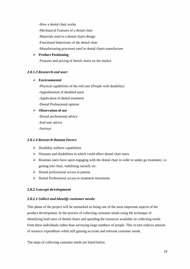
2.8.1.3 Research end user:
Environmental
-Physical capabilities of the end user (People with disability)
-Apprehension of disabled users
-Application of dental treatment
-Dental Professional opinion
Observation of use
-Dental professional advice
-End user advice
-Surveys
2.8.1.4 Research Human Facors
Disability sufferer capabilities
Diseases and disabilities in which could effect dental chair users
Routines users have upon engaging with the dental chair in order to under go treatment, i.e.
getting into chair, stabilising oneself, etc.
Dental professional access to patient
Dental Professional access to treatment intruments
2.8.2 Concept development
2.8.2.1 Collect and Identify customer needs:
This phase of the project will be earmarked as being one of the most important aspects of the
product development. In the process of collecting customer needs using the technique of
identifying lead users of dental chairs and spending the resources available on collecting needs
from these individuals rather than surveying large numbers of people. This in turn reduces amount
of resource expenditure while still gaining accurate and relevant customer needs.
The steps of collecting customer needs are listed below.
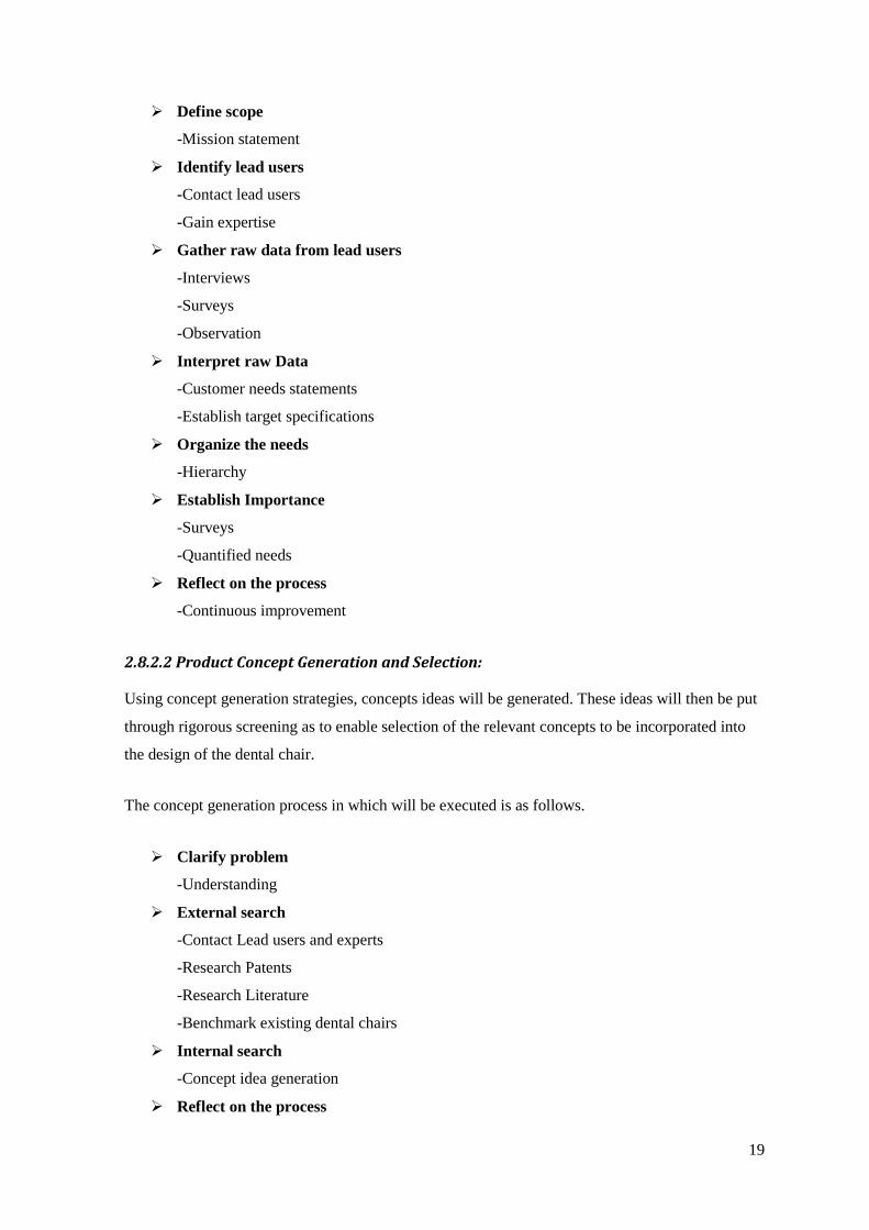
19
Define scope
-Mission statement
Identify lead users
-Contact lead users
-Gain expertise
Gather raw data from lead users
-Interviews
-Surveys
-Observation
Interpret raw Data
-Customer needs statements
-Establish target specifications
Organize the needs
-Hierarchy
Establish Importance
-Surveys
-Quantified needs
Reflect on the process
-Continuous improvement
2.8.2.2 Product Concept Generation and Selection:
Using concept generation strategies, concepts ideas will be generated. These ideas will then be put
through rigorous screening as to enable selection of the relevant concepts to be incorporated into
the design of the dental chair.
The concept generation process in which will be executed is as follows.
Clarify problem
-Understanding
External search
-Contact Lead users and experts
-Research Patents
-Research Literature
-Benchmark existing dental chairs
Internal search
-Concept idea generation
Reflect on the process

20
-Continuous improvement
The concept selection will then be conducted. The concept selection will entail as follows:
Present concepts to experts to gather opinion
Prepare Matrix
Weight each concept
Rate each concept
Select high scoring concepts
Reflect on process
2.8.3 System Level Design:
System level design entails in developing a on the product based on the concept development stage
prior. In this phase, creativity becomes a defining factor. Creative techniques will not be planned
but will be noted in the implementation description in the material and method part of this thesis.
2.8.4 Detail Design:
The detail design is the process where the product will be defined and finalised before testing. All
concepts will be set in stone and final geometries outlined and dimensioned. The phases of the
detail design can be seen below.
Produce CAD model
Produce engineering drawing of components
Produce renderings
Construct proto-type
2.8.5 Testing and refinement:
The CAD model produced will be structurally analysed with the use of the ANSYS 14.5 software
as to conduct investigation whether the chair’s design will fail under use. Also physical tests may
be done on the proto-type of the Dental chair. When results of the tests are obtained, the Final
Dental chair design can be finalised and presented.

21
2.9 Lead Users
Accurate understanding of user need has been shown near-essential to the development of
commercially successful new products. Unfortunately, typical means of analysing the market or
conducting market research are not completely reliable especially in the instance of novel type
products or in product categories characterized by rapid change such as high technology products.
Although there are techniques that can be used to gain strong consumer needs while also
considerably decreasing the time it takes to obtain them. The technique of establishing “Lead
Users” is a fundamental tool in which allows a researcher to accomplish this.
Lead users are users whose present strong needs will become general in a marketplace months or
years in the future. Since lead users are familiar with conditions which lie in the future for most
others, they can serve as a need forecasting laboratory for marketing research. Moreover, since
lead users often attempt to fill the need they experience, they can provide new product concept and
design data as well.
In regards to product design, lead users can be systematically identified, where their perceptions
and preferences can be incorporated into industrial and consumer marketing research analyses of
emerging needs for new products, processes and services. [8]
3.0 Product Research
3.1 Introduction
The following section of the literature review is the product research done in the planning phase
(phase 0) of the product development plan highlighted in section 2.8.1. In this section the research
done such as research market, existing products and end users will be outlined.
3.2 Market research
3.2.1 Disabilities in Ireland
“Disabilities” is an umbrella term, covering impairments, activity limitations, and participation
restrictions. An “impairment” is a problem in body function or structure; an activity limitation is a
difficulty encountered by an individual in executing a task or action; while a participation
restriction is a problem experienced by an individual in involvement in life situations. [17]
Disability is thus not just a health problem. It is a complex phenomenon, reflecting the interaction
between features of a person’s body and features of the society in which he or she lives.

22
Overcoming the difficulties faced by people with disabilities requires interventions to remove
environmental and social barriers.
People with disabilities have the same health needs as non-disabled people – for immunization,
cancer screening etc. They also may experience a narrower margin of health, both because of
poverty and social exclusion, and also because they may be vulnerable to secondary conditions,
such as pressure sores or urinary tract infections. Evidence suggests that people with disabilities
face barriers in accessing the health and rehabilitation services they need in many settings. [17]
The above statement suggests that disability can be a major cause of difficulty in accessing health
services and rehabilitation. A form of this is difficulty for disabled people, is accessing dental
treatment, which is very important regarding oral health. Difficulties for disabled people engaging
with dental chairs impact on the Dental treatment delivery or service. In other words difficulty in
getting in or out of the chair, or discomfort and difficulty while sitting in it may affect a person’s
outlook on the dental treatment. For example if a disabled person had extreme difficulty upon
getting seated in a dental chair, the same person may be hesitant before seeking dental treatment
again. This may be because they feel very apprehensive about going through the ordeal again of
becoming seated in the chair. Episodes like this happen on a daily basis and the statistics are there
to prove it. As is stated: “Only about one half of people with disability consider their health to be
good.” [4]
In Ireland today there are over 184.1 thousand people with a mobility or dexterity disability in
which accounts for over 4.5% of the population. [4]
People living with these disabilities face constant obstacles in everyday life. Tasks such as getting
into the shower/bath, getting into a car and other daily activities can prove difficult and in cases
intimidating. Table 1 represents the opinion on level of difficulty in everyday life of disabled
people. The table shows that people who have disabilities suffer a lot of difficulties on a daily basis
and as related back to the WHO statement, has an associate effect on general health and well-
being.

23
Table 1: Disability thresholds for each disability type in the NDS. [4]
Disability thresholds for each disability type in the National Disability Survey

24
3.2.2 Wheelchair users
A common obstacle in a wheelchair user’s life is that of chair transfer. Wheelchair users may need
to transfer from the wheelchair to other places many times a day. Because of this it is important
that wheelchair transfer is made as easy as possible. Transfers may be needed because of going to
the toilet, taking a bath or shower, changing wheelchair etc. These seem like common and simple
daily tasks to a fully capable person, but considering the work effort needed for each transfer, each
task can be exhausting to a wheelchair user. Also studies show that repetitive wheelchair transfer is
not only exhausting but can develop injury to the shoulders. Therefore wheelchair transfer should
be kept as simple and as easy as possible to lower the risk of wheelchair users developing injury.
“Both the weight-relief raise and transfer result in scapular and humeral positions and directions of
motion that may negatively impact the available sub acromial space. This may present increased
risk for injury or progression of shoulder pain in persons who must routinely perform these tasks.”
[7]
Upon entering a Dental chair in order to receive dental treatment, a wheelchair user can still
experience the same difficulty. In a lot of cases the wheelchair user does not possess the capability
of transferring to a dental chair independently. Therefore assistance is needed either from Dental
treatment staff or from family and friends. This in turn leaving the wheelchair using patient reliant
on the transferring skills of these people mentioned. A picture taken from “the Wheelchair
Transfer: A Health Care Provider's Guide” in which outlines good practice upon aiding a
wheelchair user getting into a dental chair can be seen in Figure 6.
Figure 8: Approach in which should be taken when transferring a patient into a dental chair [7]

25
3.2.3 Demographics
Below in Table 2 is taken from “the National Disability survey 2006” It is a breakdown of the
number of people with disabilities in Ireland into the disability categories as shown in the table.
Table 2: Prevalence of disability by disability type [4]
Table 2 shows that the number of Mobility & Dexterity disabilities accounts for 56% of the overall
population with disability. In which is a total number of 184 thousand people. [4]
These statistics present a huge market in the field of disabled friendly Dental chairs. As there are
specialised clinics in Ireland, there is not enough to provide people with disability ease of access to
Dental treatment. This in turn goes against the HSE’s effort in promoting oral health as, if it is
difficult to access treatment; it is more likely people won’t seek treatment.
Studies done in the National University of Ireland Galway, suggests factors in which have impact
of a disabled persons perceptions of Dental treatment. [6]
The study outlined that clinics not having adequate physical accessibility to the disabled, had
significant negative effect on a disabled person wanting to seek dental treatment. This information
presents a need to make dental chairs more disabled friendly as to further encourage and promote
oral health across the disabled population. Also referring back to the statistics presented by the
CSO 2006 survey (Table 2), with the use of disabled friendly dental chairs, considering the large
number of Mobility & Dexterity disabilities, will have a significant impact on overall oral health of
the disabled population.

26
3.2.4 Aesthetic Parameters
In this section, standard dental chair designs will be discussed where common perceptions of
dental chair and its aesthetics will be noted and outlined.
In figure 7 are pictures taken of the dental chair in the Mayo General Hospital, Castlebar. This
chair is a standard model dentist chair. It can be said that this type of chair can be represented as
what a normal persons perceptions of what a dental chair is.
Figure 9: Dental chair situated in Mayo General Hospital, Castlebar
As can be seen in the pictures above, the chair has primary features that can be seen across most
dental chair design. These features are listed and described as follows.
Arm-rest
Head-rest
The Unit The Spittoon
Back-rest
Seat

27
Feature 1: The Delivery system
The delivery systems are composed of two components. One component is the sink which is
known as the “Cuspidor” or “Spittoon”. This is where a patient may take a drink or spit out after
rinsing ones mouth.
The second component is the “cart” or “unit”. This is an important component of the dental chair.
It holds the Dental utensils in which a dentist will use while treating a patient. The position of the
“unit” can determine the efficiency of the dental treatment i.e. if a dentist has to stretch over to
reach for a utensil this in turn slows down treatment time and may cause fatigue on the dentist
should he/she be treating many patients throughout a working day. Usually the delivery systems
are fixed to the back of the chair or to the sides. It can be said that the larger the movement
envelope of the delivery components the better the service they provide.
Feature 2: The Seat
The seat on a standard dental chair is an elongated support in which integrates the seat for the
buttocks with the legs rest as one rigid structure. This structure is usually ergonomically shaped so
the human body can comfortably fit into the chair.
Feature 3: The Back Rest
The back rest on most common dental chair design are just simple back rests in which you would
see on any type office chair or seat. Usually they have very slight ergonomic shaping to improve a
patient’s comfort when seated.
Feature 4: The Arm Rests
On most dental chair designs the arm rests are rigid structures protruding from either side of the
seat. They are not usually detachable but on some models they can be rotated up or down like can
what be seen on the armrests of a bus.
Feature 5: The Headrest
The headrest on a typical dental chair is just a simple headrest which is mechanised to traverse up
(away from the back rest) and down (toward the back rest). This is to incorporate people of taller
stature. On most designs the headrest is merely that, there is no neck support provided.

28
3.2.5 Environmental
In designing the dental chair the author will follow ISO 6875:2011 Dentistry - Patient Chair. ISO
6875:2011 outlines specifications in which the design and function of the dental chair needs to
abide by. An important spec outlined in the standard is that the chair not fail or topple over when
loaded by a patient of at least a mass of 135 kg. In designing the disabled friendly dental chair the
author will not only be looking to satisfy the customer needs but designing a chair that will satisfy
ISO 6875:2011. These standards can be seen in Appendix 4.

29
3.3 Existing Product research
In this section the research done investigates existing dental chairs on the market. In investigating
the market of top of the range dental chairs, there were three outstanding models of interest. These
models were chosen for the reason that if this project’s output of a final product design were to be
entered into the market these three models would be the products primary competitors.
The models chosen for research can be seen listed below.
Belmont 037/039
Planmeca chair
KaVo 1058 compact
3.3.1 Belmont 037/039
The Belmont 037/039 dental chair range incorporates a ground breaking concept. This is the
concept having a knee break in the seat component of the chair. Having an incorporated knee break
can solve many problems. For one, it means someone transferring from a wheelchair to the dental
chair can do so as if they were transferring into an ordinary chair. Below is a picture taken from
the Belmont 037/039 user’s manual.
Figure 10: Belmont 037/039 dental chairs (Belmont, 2014).
From scrutinising the Belmont 037/039 models, a pros and cons list was compiled to establish
concepts to take forward to the design phase and concepts to try and enhance.

30
Table 3: Pros and Cons list of the Belmont 037/039 Dental chair models.
Pros Cons
Knee Break
Knee break gives easier access to the
disabled and even easier access to fully
capable people.
Headrest
Headrest offers no support to the neck.
Small base footprint
The base does not take up as much space as
standard dental chair models. Thus leave
greater free space around the chair.
Armrests
The arm rests are not detachable and may
present a difficulty in wheelchair users
transferring to the chair.
Foot extension
The foot extension gives greater leg support
to someone who is large in height.
Backrest
The backrest is poorly ergonomically
shaped. The backrest does not provide
adequate support to the upper-body of the
patient.
From analysing the Belmont 037/039 dental chairs, two possible concepts to be taken into the
design stage were established (as can be seen in Table 3). These were the knee break and the
reduced size of the base footprint. These concepts will be considered in the concept development.

31
3.3.2 Planmeca chair
The Planmeca chair is a more recent model of chair. It takes the concept of the Knee break in the
seat while also incorporating the concept of detachable arm rests. Pairing these alongside the fact
that the base footprint is smaller again then that of its Belmont counterpart, This chair is designed
to suit the needs of a disabled person. Shown below is a picture of the Planmeca chair taken from
the Planmeca website.
Figure 11: Planmeca dental chair [11]
From scrutinising the Planmeca model, a pros and cons list was compiled to establish concepts to
take forward to the design phase and concepts to try and enhance.

32
Table 4: Pros and Cons list of the Planmeca Dental chair model.
Pros Cons
Knee break
The Knee break as mentioned with the
Belmont model gives easier access. Also
this models knee break is “invisible” when
the seat is fully elongated out.
Headrest
Headrest offers no support to the neck.
Detachable arm rests
The detachable arm rests means that a
wheelchair bound patient can access the
dental chair with easier.
Chair Height
Comparing the Planmeca model with the
Belmont models, the chair can only lower
to 495mm from the ground when the Knee
break is at 90 degrees. Whereas the
Belmont can lower to 455mm.
From Table 4 it can be seen that the Planmeca design has two desirable concepts. These are the
Knee break and the detachable arm rests. These concepts shall be considered in the concept
development phase.

33
3.3.3 KaVo 1058 compact
The KaVo 1058 compact dental chair design incorporates two potentially interesting concepts of
both the Knee break and the retractable footrest. It also has rigid arm rests that retract like that of
the armrests on a bus. The Footprint of the base, like in the other models is reduced and offers a
greater amount of free space around the chair. Below in Figure 10 the KaVo 1058 Dental chair can
be seen.
Figure 12: KaVo 1058 dental chair [10]
From scrutinising the KaVo model, a pros and cons list was compiled to establish concepts to take
forward to the design phase and concepts to try and enhance.

34
Pros Cons
Knee Break
The knee break as mentioned in the other
two dental chair model present easier access
to the disabled.
Head rest
Headrest offers no support to the neck.
Foot extension
The Foot extension gives greater leg
support to those who are large in height.
Armrests
Although the armrests can rotate or fold
down and up, they are not fully detachable
and may cause obstruction to a wheelchair
bound patient trying to gain access to the
chair.
Table 5: Pros and Cons list of the KaVo 1058 Dental chair model.
The KaVo 1058 design represents the most optimal design as it seems to incorporate most of the
good features of the other two Dental chair models.
Conclusion
Considering the three Dental chair models; there a number of good concepts that can be considered
in the concept development phase. On the other hand there are a number of considerations that the
chairs have not taken into account. In none of the chairs has the concept of supporting the neck
been considered. Also the Back rest of all the chairs had very little upper body supports (such as
that as in a Bucket seat in a Rally car) in order to stabilise a patient while under treatment. All
these factors can be brought forward into the concept development phase, and depending on the
customer need statements may be used.

35
3.4 End user Research
In this section the capabilities and preferences of the end users will be discussed. The two areas in
which will be investigated will be ways in which wheelchair user’s transfer from the wheelchair
into other seats and positions Dentists and dental professionals take while treating patients. This
research was conducted because when trying to develop a final design it is important to understand
the approach the end users of the product take when engaging or using the product.
3.4.1 Wheelchair Transfer
Wheelchair transfer is the term used in describing the technique used in a wheelchair user getting
out of the wheelchair. When designing furniture in which are to be wheelchair user friendly, it is
important to understand wheelchair transfer techniques. Below in Figure 11 is a picture taken from
a study by the University of Pittsburgh on lower extremity weight bearing upon wheelchair
transfer.
Figure 13: Three techniques used upon transferring from a wheelchair [16]

36
In figure 13 it can be seen that within every transfer technique shown, the wheelchair is positioned
in an angled orientation positioned as close to the chair as possible. This wheelchair approach is
known as the diagonal approach. In each wheelchair transfer (a, b and c) the person is executing
different approaches of raising and transferring oneself. In (a); the person uses the front and side
most distant from himself on the chair to place his hand. In (b); the person grips the side-edge
closest to himself. Finally in (c); the person executing the transfer has his hand placed more
centrally to the chair. From this information it can be noted that when designing a chair that is to be
wheelchair user friendly, the seat component itself should be designed to enable these type of
wheelchair transfers. For example if someone wanted to perform a transfer like what’s shown in
Figure 14 picture (b), then the seat should be design that the edges are rigid and have adequate grip
to provide safe transfer.
While considering the three techniques of transferring oneself from a wheelchair, it is also
important to consider the positional approach of the wheelchair used when seeking to execute a
transfer. Below in Figure 14, these two approaches are outlined.
Figure 14: Positional wheelchair approach of someone trying to execute a wheelchair
transfer [14]

37
As can be seen in Figure 14 the two approaches are the “Diagonal approach and the “Side”
approach. When developing a design for furniture that is to be wheelchair friendly it is important
that these approaches are considered and that adequate free space is incorporated around the
furniture piece to enable either approach of transfer.
3.4.2 Dental Professionals
In designing a dental chair it is important to understand the point of view of the dental
professionals themselves. It is important to understand their relationship with a dental chair and
their interactions with it. It can be seen in Figure 15 various dental treatment being delivered.
Figure 15: Various dental treatment being delivered (Google images)

38
As can be seen in figure 15; when delivering treatment, a Dentist needs to be able to position
him/herself quite close to the patient. From this, it can be noted that free space is needed from
either side to allow a dentist access to the patient. It can also be noted that the thickness of the
backrest will need to be considered as to allow the knees of someone delivering treatment be in a
comfortable position. Also that the dental chair base footprint size has a direct effect on the free
space available, it is important that this factor be considered in design.

39
4.0 Material and Methods
In this section the gathering and application of the customer needs will be highlighted. The process
of reaching the final design and how it was achieved will be outlined. Finally in this section is the
prototyping of the final design and how it was fabricated.
4.1 Customer needs
The method in which the customer needs were gathered was by identifying dental chair lead users
and gathering data from these individuals. The author identified three primary lead users of dental
chair in particular. These can be seen listed below.
Dental professional
Dental Chair Expert
Wheelchair user
Dental professional
The author gained contact with a Dentist based in University College Cork who specialises in
special needs dentistry. From interviewing the dental professional over the phone, the author
gained insight into various disabilities in which might be overlooked by dental chair
manufacturers. He also gave the author some ideas of his own in how dental chairs can be
improved.
Dental Chair Expert
From contacting a local dentist in the Castlebar area the author got in touch with a dental chair
installation and maintenance engineer. The author then met with the engineer in the Mayo Genaral
Hospital in Castlebar, Co. Mayo dental clinic. The author was then shown a demonstration of how
dental chairs function. He also presented the author with some examples and ideas of how the chair
can be improved.
Wheelchair User
Through this projects supervising lecturer, the author gained contact with a wheelchair user. The
author compiled a survey in which was filled out by the wheelchair user. She presented the author
with various ways in which dental chairs can be improved and reasons for which standard dental
chair designs can be difficult for people in wheelchairs.

40
From gathering information from these “dental chair” lead users the author then compiled a list of
useful concepts and ideas which could be brought forward into the design phase. This list can be
seen in figure 16.
Figure 16: Customer Needs Raw Data

41
From the list shown in figure 16 the author funnelled this list to centrally focus on a couple of
elements in particular. In funnelling the list the author decided what could actually be achievable
considering the resources and time constraints and whether if the idea would actually be feasible.
The two pieces of information in which the author decided to address can be seen listed below.
Height of chair
Increased access for wheelchair users
The element of chair height was chosen as it is a major factor in how easily someone in a
wheelchair transfers into a dental chair. Increased access was also decided to be a main priority in
this project as in standard dental chairs the actual design features makes it difficult to perform
wheelchair transfer.

42
4.2 Concept Generation
In this section the concept generation phase will be outlined. Various mind maps and other forms
of ideas used in developing the final design will be discussed.
4.2.1 Mind Mapping
As part of the concept generation process mind mapping was used in order to generate a large
number of ideas. Figure 17 shows one of the mind maps constructed in the concept generation
process.
Figure 17: Concept Generation Mind Map

43
4.2.2 External Search
From consulting with the lead users and various colleagues further ideas were generated. Figure 18
shows a few of these ideas.
Figure 18: External ideas

44
4.3 Concept Selection
The concepts in which were under selection were the ideas generated in lifting and lowering the
chair. They weighted from 1-5 under three different criteria. The first was functionality.
Functionality was in terms of how high and low the lifting mechanism can go while also not being
an irrational or over the top concept. The second criterion was the likelihood of success. This was
in terms of the concept idea actually going to lift and lower the chair successfully without failure.
Ease of implementation was the final criterion. Scoring the concept ideas against this gave an idea
of which idea was best to implement in terms of it achievability considering the resources and time
constraints of the project.
Concept Functionality Likelihood of
success
Ease of
implementation
Score
Jack 3 4 4 11
Scissor 4 4 4 12
Telescopic 3 3 2 8
Lead screw 2 2 3 7
Rack & Pinion 3 4 2 9

45
4.4 Final Design
This section will outline the final developed design. Each feature of the final design is explained
and outlined with the use of CAD modelling. The final chosen design can be seen in figure 19.
Figure 19: Final Design
As can be seen in figure 19 (Also refer to figure 21) the final design is a simplistic but yet
innovative approach into giving greater access to wheelchair users in transferring into the dental
chair. The design frees up space both in front and to either side of the chair to allow for almost any
type of wheelchair transfer. As can be seen the seat itself is split into two components, the seat base
and a retractable footrest. The chair is also raised and lowered by a scissor lift which is actuated by
a lead screw. The seat back can be brought up to 90˚ and lowered down to 170˚. The chair can also
be lowered to a height of 670mm which is an ideal height for those perform in wheelchair transfer
as the person can lower themselves down into the dental chair. Figure 20 shows the height
comparison of the dental chairs lowest point and the average height of a wheelchair.

46
Figure 20: Dental Chair at Lowest Point
The chair is primarily comprised of a seat, retractable footrest, backrest, armrests and scissor lift.
These features are shown in figure 21.
Figure 21: Final Design Features

47
4.4.1 The Scissor Lift
The scissor lift is composed of 40mm * 15mm mild steel cross members. In total there are 12 of
these cross members making up the scissor lift. They are connected with Ø16mm silver-steel pins.
At the bottom of the scissor lift the members are connected to sliders to allow the lift to extend and
retract. The sliders are connected to a lead screw which powers the raise and lowering of the lift.
At the top of the scissor lift, runner wheels are connected to the cross members. These runner
wheels bear the load of the chair itself and of the patient sitting in the chair. The scissor lift
assembly can be seen in figure 22.
Figure 22: Scissor Lift

48
4.4.2 Connection between Lift and Chair
The Scissor lift is attached to chair via a 5mm thick mild steel cap which is positioned on the
runner wheels. The cap transfers the load of the chair and patient onto the runner wheels. The cap
can be seen in figure 23.
Figure 23: Scissor Lift Cap

49
4.4.3 Seat base
The seat base as shown in figure 24 is composed of a 25mm box iron structure. Connected under
the seat is two runner bars to allow the footrest to extend and retract underneath the seat. At the
back of the seat there are also connection tabs in where the back rest will be positioned.
Figure 24: Seat Base
4.4.4 Retractable footrest
The retractable footrest is made out of 19mm box iron. The under the footrest 19mm box iron
runners are connected to slot inside the runners of the seat as shown in figure 24. The extension
and retraction operation will be operated by a lead screw attached to the footrest. The footrest can
be seen in figure 25 below.
Figure 25: Retractable Footrest

50
4.4.5 Backrest
The back and head rest are made up of 25mm box iron structure. The back rest is fixed to the seat
based via connection tabs positioned at the back of the seat base. The raise and lowering of the
back rest is operated by a bevel gear system which transfers the rotation of the motor into the
rotation of back of seat.
Figure 26: Seat Back
4.4.6 Arm Rests
The arm rest are made up of mild steel circular tubing which are fixed to circular mild steel plates.
On these plates there is 10mm mild steel dowel protruding which slot into the holding plate which
are fixed to the scissor lift cap.
Figure 27: Arm Rests

51
4.5 Prototype
In this section the final design prototype will be described in detail. The manufacturing process
will also be outlined.
4.5.1 Introduction
As the resources and funding for the final year projects were limited the author decided the best
approach in prototyping the final design was to fabricate a scale model. Manufacturing a scale
model prototype still presents most of the integrated concepts of the final design and demonstrates
the final design functionality. The scale chosen for the model was 1:2 or in other words half the
size of the original design.
4.5.2 Completed prototype
The scale model prototype as shown in figure 28 demonstrates the concept of the scissor lift, the
cantilevering of the chair and also the retractable footrest. All the components were scaled down as
accurately as possible to get a model as close as possible to the final design. As resources and
materials available were limited, there were some slight variations made in order to fully construct
the model.
Figure 28: Dental Chair Prototype

52
4.5.3 Manufacturing Process
The dental chair model has three primary assemblies and these are listed below.
The chair
The scissor lift
The slider system
The three assemblies can be seen in figure 29 below.
Figure 29: Prototype Assemblies
These three assemblies will now be described and also how they were manufactured will be
outlined.
Chair
Scissor lift
Slider system

53
The Chair
The chair is comprised of a wooden structure. First of all the frame itself was made by cutting
25mm timber to size. The timber was then fixed together using wood glue, panel pins and screws.
Then the frame was fitted with 5mm plywood as to give the frame a seat like appearance. A drawer
like mechanism was also made which was to represent the retractable footrest. This was fixed
under the seat base. The prototype chair manufacturing phases can be seen in figure 30.
Figure 30: Prototype Chair
To make the footrest on the prototype extend and retract a lead screw and motor were connected to
the chair. This was done by firstly cutting a piece of threaded bar to size, then making an
aluminium connector attaching the 12 volt motor to the threaded bar. A special elongated nut was
then fitted to the back of the footrest. The motor was then positioned and fixed into place
underneath the chair. As the motor is turned on, the lead screw will turn and depending on which
way the motor is turning the footrest will extend or retract. The leg rest mechanism can be seen in
figure 21.
Figure 31: Footrest Mechanism

54
The Scissor Lift
In constructing the scissor lift first of all the cross members were made. 6 mm thick mild steel bars
were cut to length (250 mm). Then on each member three 6 mm holes were drilled in order to
accommodate the pins. There were 8 cross members made in total. The pins were then fabricated
from 6 mm silver steel which was threaded at both ends to allow a nut to hold the pins in position.
Small brackets were then made out of 25mm box iron to hold the lift onto the slider. These
components can be seen in figure 32.
Figure 32: Scissor Lift Assembly
Pins
Brackets
Cross members

55
Slider Mechanism
The slider mechanism in the prototype uses a lead screw to traverse the sliders. The lead screw and
sliders used in the prototype were salvaged from a broken 3-D printer. The sliders consist of a
bearing which is fixed in place and a lead nut slider which traverses along the track with rotation of
the lead screw. The tracks themselves were also salvaged. The author managed to obtain the
aluminium profile from old Control lab components which were no longer in use and ready to be
scrapped. The tracks were then fixed to a base with mild steel brackets. The base was made from
10mm chipboard. The slider mechanism can be seen in figure 33.
Figure 33: Slider Mechanism
The motor was then connected to the lead screw using grey steel collaring with grub screws
holding the collar in place. A bracket was made to hold the motor into position. This bracket was
then fixe to the base. The motor, collar and bracket can be seen in figure 34.
Figure 34: Motor, Collar and Bracket
Collar
Motor
Bracket

56
4.6 Testing
In this section the final design will be tested in various methods. Calculations have been performed
on various aspects of the dental chair to gain insight into whether or not the chair would fail under
use and on various aspects on how it performs. The test and calculations being performed can be
seen listed below.
4.6.1. Finite Element Analysis to see would the Scissor lift function under a load.
4.6.2. Calculation to find out what load is acting on the lead screw.
4.6.3. Calculation to find out the torque required to raise the chair.
4.6.4. Calculation in finding out what is the magnitude of bending moment acting on where
the chair is cantilevered.
4.6.5. Calculations of various ways the bending moment can be alleviated.

57
1. Finite Element Analysis
In conducting the Finite Element Analysis the author chose to analyse the scissor lift. What was
being analysed was whether the scissor lift would withstand the weight of the chair and patient
without buckling. To perform the Finite Element Analysis the ANSYS 14.5 software was used.
The scissor lift was modelled using beam elements. Loads were applied and then a non-linear
buckling analysis was conducted. The Buckling analysis determined that the scissor lift will buckle
under the load of 31,342 N. Putting this in perspective is the weight of 3,194.9 kg. This means that
the designed scissor lift complies with ISO 6875:2011 Dentistry-Patient Chair. Although
considering the scissor lift only needs to bear the weight of 1485.9 N (151.466 kg) the scissor lift
designed by the author may have to be revisited as the bucking analysis results show it is over
designed. The Finite Element Analysis report can be seen in Appendix 3.

58
2. Calculation to find out what load is acting on the lead screw
In this section the load acting on the pins and lead screw when a patient is sitting in the chair will
be calculated. The mass of the patient sitting in the chair being assumed is in accordance with ISO
6875:2011 Dentistry - Patient Chair.
The formula for finding the axial load acting on the lead screw can be seen in Equation 1.
Equation 1: Force Acting on Lead Screw
Where:
W = Weight of chair and patient
= Angle of cross member from the ground
Equation 1 was derived from a summary of the forces of the entire scissor lift. This derivation can
be seen in Appendix 1 (Dental Chair Analysis Report 1).
Assuming the chairs mass is 16.466 kg and the patient’s mass is 135 kg and that the angle in which
the chair is 20⁰ from the ground when chair is at its lowest point.
Knowing this, the load on the lead screw when the chair is at its lowest point is calculated below.
( ) ( )
Equation 1 was then used to find the axial force acting on the lead screw at each increase of 1
degree in angle from the ground starting at 20⁰ and finishing at 45⁰. This data shows that the higher
the scissor lift is lifted the less load acting on the lead screw. Refer to Appendix 3 to see the
calculated forces using Microsoft Excel. Figure 35 gives a representation of every degree in which
the cross member increases from the ground that the axial load on the lead screw decreases.

59
Figure 35: Force on Lead Screw Graph
Conclusion
In calculating the force on the lead screw the torque required by the motor to raise the load can
now be calculated.
3. Calculation to find out the torque required to raise the chair.
In this section the torque required to turn the lead screw in order to raise the chair will be
calculated. In order to be able to calculate the torque required first of all the lead screw dimensions
need to be specified. They are as follows.
Thread depth = 2mm
Thread width = 2mm
Major diameter = 32 mm
Mean diameter (dm) = 30mm
Root diameter (dr) = 28mm
Lead = 8mm
The coefficient of friction for threads = 0.14
Also the assumption will be made that all other friction occurring are negligible.
The formula used to find the torque required to raise the load can be seen in Equation 2.
0
1000
2000
3000
4000
5000
20 22 24 26 28 30 32 34 36 38 40 42 44
Force on lead screw (N)
Force on lead screw
Angle of cross
member from
ground
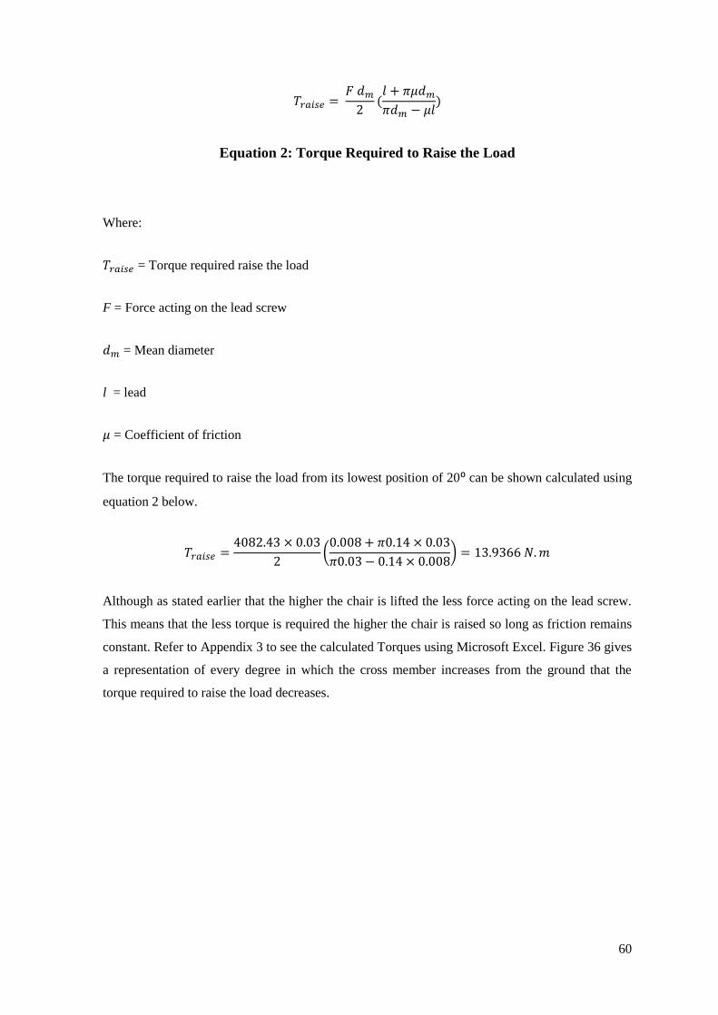
60
(
)
Equation 2: Torque Required to Raise the Load
Where:
= Torque required raise the load
F = Force acting on the lead screw
= Mean diameter
l = lead
= Coefficient of friction
The torque required to raise the load from its lowest position of 20⁰ can be shown calculated using
equation 2 below.
(
)
Although as stated earlier that the higher the chair is lifted the less force acting on the lead screw.
This means that the less torque is required the higher the chair is raised so long as friction remains
constant. Refer to Appendix 3 to see the calculated Torques using Microsoft Excel. Figure 36 gives
a representation of every degree in which the cross member increases from the ground that the
torque required to raise the load decreases.

61
Figure 36: Torques Required to Raise Load Graph
Conclusion
In calculating the force required to raise the load it was found that when the chair was lowest to the
ground this needed the largest amount of torque. This was found to be 13.9 N.m. This means that
the motor to be used in the design must have and output torque of at least 14 N.m.
0
2
4
6
8
10
12
14
16
20 22 24 26 28 30 32 34 36 38 40 42 44
Torque required to raise load (N.m)
Torque required toraise load (N.m)
Angle of cross
member from
ground

62
4. Calculation in finding out what is the magnitude of bending moment acting on where the
chair is cantilevered.
It was calculated that the bending moment acting on the top of the scissor lift was 758.254 N.m.
These calculations can be seen in Appendix 2 (Dental Chair Analysis Report 2).
Conclusion
From calculations, the author noted that the bending moment acting at the point of where the dental
chair is cantilevered was great as it amounted to 758.3N.m. Putting this in perspective it is the
equivalent of placing a 77kg mass on the end of a metre stick. In order to satisfy ISO 6875:2011
the chair must be able to lift a patient without failure or toppling over. From the bending moment
calculated the author can now look at ways in which ensure that toppling or failure would not take
place.
5. Calculations of various ways the bending moment can be alleviated.
For alleviating the bending moment on the top of the scissor lift two ideas were analysed
theoretically. The idea having a counter weight at the back of the chair was looked into and also
the idea of having an extra leg support underneath the footrest was investigated. It was calculated
in order to fully alleviate the bending moment of a fully loaded chair a counter weight of 643.5N
(65.6kg) must be applied. Also if the extra leg support were to be chosen it would have to be
designed to at least bear the weight of 650.8N (66.34kg) in order to support the loaded chair.
Refer to Appendix 2 (Dental Chair Analysis Report 2) for calculations.
Conclusion
The two design ideas would work in alleviating the bending moment but both these design ideas
are not entirely practical as the counter weight would further load the scissor lift increasing the
torque required by the motor to raise the load. Also the extra leg support would also have its
impracticalities as the end user of the dental chair may forget to use it.

63
5.0 Discussion
In this section the project as a whole will be discussed. The discussion includes the selection of the
product development process used in this project, the Research conducted, the final design
achieved, the design prototype and the calculations results.
The project firstly began with investigating various product development process models. The
product development models investigated were the Stage Gate process, Total design process and
the Eppinger process. From investigating the three development processes the author selected the
Eppinger process to use as a template in conducting this project. The reason of which the author
chose this process was because the Eppinger process had detailed instruction in how to accomplish
each stage of the process. Upon selection of the process it was then tailored to fit the scope and
timeframe of the final year project. Various phases of the process were changed or slightly altered.
The major area that was changed was phase five which comprised of production ramp up of the
final product. As this was an academic project, it was decided to change phase five to the
presentation of the final design as the final product was not being brought to market. From this the
author assigned tasks and deadlines for each phase of the development process in order to further
give the project structure in its execution. These tasks and dates were inserted into MS project
which was used to continuously track the project.
Following the tailored Eppinger process, the research phase began on the project. From the
research the author gained insight into a market need for further developments in dental chair
design to make it easier for disabled people to access them. Also various wheelchair transfer
techniques were investigated which gave insight into what is the problem with standard dental
chair designs which further backed up the case of a need for further developments needed in dental
chair design. The author also researched existing dental chairs on the market, and from this, the
author gained some valuable ideas to bring forward to the next phase which was the concept
development phase.
The concept development phase began with capturing the customer needs. To do this the author
used the techniques described by Eric von Hippel in identifying lead users. The lead users
contacted by the author were a dental professional, a dental chair engineer and a wheelchair user.
From interviewing and surveying the lead users the author was able to compile a list of customer
needs statements. Using this, the author targeted two main customer needs when developing the
design and they were the height in which the chair could be lowered and to make it easier for
wheelchair transfer be made onto the chair. From outlining these objectives the author then
conducted various creative techniques in generating concepts that will satisfy the newly established
customer needs. From talking to the lead users and conducting more existing technology research

64
the author gathered a substantial amount of ideas to bring forward to concept selection. To funnel
down these ideas the author compiled a scoring matrix where each concept was scored according
to its performance against the elected criteria. The concept in which scored the greatest was then
selected to be developed into the final design.
In the developing the final design, the author sketched many ideas of how the chosen concepts
would be integrated. Also primitive CAD prototypes were made to gain further insight. From the
cycles of sketching ideas and modelling CAD prototypes the final design was achieved. The final
design was then accurately modelled on CAD from which the prototype was based.
As resources and time was limited the author decided that the prototype was going to be a scaled
down model of the final design. The scale selected was 1:2 or in other words half the size. In
fabricating the prototype, the author had many complications in trying to scale down the design as
materials available were limited. The author decided to outline the important features in which
needed to be presented by the prototype. The two major features outlined were the scissor lift and
the retractable footrest. From outlining these two features the author successfully developed a
functioning prototype.
The design was then looked into in a technical sense. Various calculations and tests were
performed on the final design. These tests gave the author feedback on where the final design
needed further enhancement and improvement. One aspect where the author noted where
improvement could be made was of the large bending moment acting on the top of the scissor lift.
The author then came up with two undeveloped ideas to alleviate this bending moment but these
ideas would need further development and thus were not then incorporated into the final design.

65
6.0 Conclusion and Recommendations
This section will conclude on the thesis report. The outcomes of the project work done and its
respective results will be outlined. Recommendations will also be made for the project in where if
it is to be undertaken again. The section is broken down into the product development process and
its effectiveness in its execution, then the final design achieved and its performance in terms of
satisfying the customer needs will be concluded.
6.1 Product Development Process: Eppinger Process
The Eppinger product development process was elected to follow in executing this project. As
part of the Eppinger process it is important to reflect on every stage of the product development as
to ensure that the process is continuously improved. Below each phase from phase 0 to 5 will be
discussed, highlighting how the process can be improved.
Phase 0
In before executing phase 0 gain clarity in what wants to be achieved by the project. The author
found that after phase 0 a lot of time was spent researching on areas in where when the project
gained further clarity this research seemed redundant. In this project more time could have been
spent on researching actual existing technology and this change could most definitely improve on
the process.
Phase 1
In this phase the customer needs were quite accurately gathered. Although the author felt that if
more contact was made with people who rely on wheelchairs, a more comprehensive customer
needs list would have been achieved.
Phase 2
In executing phase 2, there were a number of aspects in which could improve the process. If early
testing was conducted even at this early stage, it would have meant the final design could have
been more easily achieved, as the author found that some aspects or features being brought through
to testing and refinement had to be revisited after testing and calculation, meaning phase 2 had to
be revisited numerous times.
Phase 3

66
In constructing the prototype the author found difficulties in scaling down the final design. In this
project a scale was selected and then a material search began to try and source materials which
would be adequate to the scaling. If the material search was done first and then the scale of the
prototype was selected upon the materials available this would dramatically improve both process
and the final prototype.
Phase 4
If preliminary testing was done in Phase 2 this would reduce the chance of having to make
alterations to the design when reaching Phase 4.
Phase 5
Phase 5 seemed to run smoothly so there would be little or no change required for this phase.
Overall the Eppinger process used seemed quite effective although the conclusion can be made
that if testing was to begin at Phase 2 the overall process would be improved.
6.2 Final Design
The final design achieved satisfied the two customer needs collected from the lead users, which
were to reduce the height of chair and give increased access to wheelchair users. From the testing
done on the final design, the author found that the scissor lift in the design would not fail in lifting
a load of a 135 kg patient and the weight of the chair itself. Although as the scissor is not fixed to
the chair on its centre of gravity this means there is a large bending moment acting on the scissor
lift. With the time constraints of the project the author was unable to verify whether the scissor lift
would fail under this bending moment and therefore cannot conclude that the scissor will not fail.
Therefore the author would like to make the recommendation that further testing and analysis be
done on the design to establish whether the scissor can withstand the bending moment. As can be
seen in Appendix 2 the author devised two methods of alleviating this bending moment. Another
recommendation the author has made is to spend further time developing on these concepts in
order to improve the dental chair design.

67
6.3 Recommendations
Upon reflection on the project there were a number of aspects in which the author would make
recommendation. In the execution of the product development process amendments should be
made to phase 2 to begin preliminary testing at this phase. This would ensure that when more in
depth testing is done in phase 4 that major alterations to the design would not have to be made.
Also for future work the author would recommend that a finite element analysis be conducted upon
the scissor lift to see if the scissor lift will buckle under the bending moment caused by the loaded
chair. The author will also advise that the two concept ideas outlined in Appendix 2 be further
investigated and developed as to alleviate the bending moment acting on the scissor lift.

68
7.0 Appendices

69
Appendix 1: Dental Chair Analysis report 1 (Torque Required to Raise
Load)

70
Contents
Introduction ........................................................................................................................................... 71
What is being analysed? ........................................................................................................................ 72
Examples of scissor lifts and where they are used ................................................................................ 73
Finding the power needed to raise load. ................................................................................................ 74
Magnitude of the loads ...................................................................................................................... 75
Finding the component of force acting on the lead screw ................................................................. 76
Dimensions of the lead screw ............................................................................................................ 80
Torque required to raise load ............................................................................................................ 81
Power needed to raise chair ............................................................................................................... 83
Energy needed to fully raise chair ......................................................................................................... 84
Discussion ............................................................................................................................................. 85
Conclusion............................................................................................................................................. 86
References ............................................................................................. Error! Bookmark not defined.

71
Introduction
The scope of the major project is to design a dental chair in which will have enhanced accessibility
to wheelchair users. In order for the chair to be still classed as a dental chair it must have the
following functions.
The chair must be able to be raised and lowered.
The chair must be able to support the weight of a patient of at least 135kg and its
additional self-weight.
The chair must not tip or lift off the ground when loaded or unloaded.
These three requirements were taken from ISO 6875:2011 (Dentistry patient chair).
In this report the design in which has been achieved for the chair is going to be analysed. The
Design will be theoretically placed under a load of 135 kg. Then torque on the lead screw required
to raise the load will be found, in turn the power needed by motor to raise the load can then be
found. Using this power rating the energy consumption to fully raise chair to max height when
loaded will be then calculated.

72
What is being analysed?
In the below design the wheelchair friendly dental chair incorporates a scissor lift mechanism in
which raises and lowers the chair. A scissor lift or “Jack” mechanism is a device used to extend or
position a platform by mechanical means. The term “Scissor” comes from the mechanism utilized
which is configured with linked, folding supports in a crisscross “X” pattern. The extension or
displacement motion is achieved applying of force to one of the supports resulting in an elongation
of the crossing pattern.
The force applied to extend the scissor mechanism may be hydraulic, pneumatic or mechanical (via
lead screw or rack and pinion system).
It will be this scissor lift mechanism in which is adopted into the wheelchair friendly dental chair
design that will be analysed in this report. In order for the scissors to function an applied force is
needed to the lift members. In this case a lead screw connected to a motor will traverse one of
members along a slider to elongate the scissors lift. In this report the applied torque needed from
the motor onto the lead screw in order to lift the load will be calculated. Also the power needed by
the motor and the energy consumption of the motor when fully lifting the chair to max height will
be calculated.
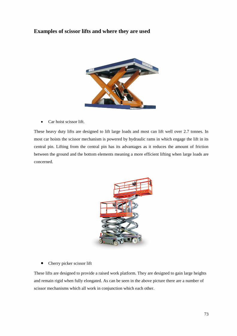
73
Examples of scissor lifts and where they are used
Car hoist scissor lift.
These heavy duty lifts are designed to lift large loads and most can lift well over 2.7 tonnes. In
most car hoists the scissor mechanism is powered by hydraulic rams in which engage the lift in its
central pin. Lifting from the central pin has its advantages as it reduces the amount of friction
between the ground and the bottom elements meaning a more efficient lifting when large loads are
concerned.
Cherry picker scissor lift
These lifts are designed to provide a raised work platform. They are designed to gain large heights
and remain rigid when fully elongated. As can be seen in the above picture there are a number of
scissor mechanisms which all work in conjunction which each other.

74
Finding the power needed to raise load.
In order to find the motor efficiency the following formulas and information is needed.
1. Magnitude of load
2. The dimensions of the lead screw as listed below
o Pitch
o Single or double threaded
o Coefficient of friction
o Thread depth
o Thread width
o Pitch diameter
o Minor diameter
o lead
3. Torque required to raise the load
Also the following formulas are needed.
Where
P = power
T = Torque required to lift the load

75
In most dental chairs 12 volt motors are generally used that have a rotational output of 110 R.P.M.
or 52.521 rads/second. This will be the motor selected to be used in this analysis.
Magnitude of the loads
In compliance with ISO 6875:2011 (Dentistry patient chair) the mass of 135kg will be used in
loading the chair. Self-weight will be ignored in this analysis. Note 135kg is equal to 1324.35 N.
Note: As the lead screw is not taking just taking the load of 1324.35 N. The component of force
that is acting on the lead screw needs to be found.
1324.35 N

76
Finding the component of force acting on the lead screw
The total load in the chairs is 1324.35 N. This is not the force that will be put into the torque
formula as it is the load acting upon the lead screw (down the axis of the lead screw) is the force
that needs to be considered. Here this component of force will be found.
Wheel Chair Friendly Design:
512mm
20.7 degrees

77

78

79

80
Dimensions of the lead screw
The dimensions of the power screw to be used in the calculations are listed below.
Thread depth = 2mm
Thread width = 2mm
Major diameter = 32 mm
Mean diameter (dm) = 30mm
Root diameter (dr) = 28mm
Lead = 8mm
The coefficient of friction for threads = 0.14
662.175 N
3504.790 N
Note:
As the lead screw will
only be bearing the load in
the x direction it will be
3504.790 N used when
calculating the Torques for
raising.

81
Torque required to raise load
The torque required to raise load will now be calculated. Coefficient of friction on elements of the
chairs will be ignored and only power screw threads friction between nuts will be taken into
account. Also there is no collar friction so this is also being ignored.
Dimensions of the lead screw:
The dimensions of the power screw to be used in the calculations are listed below.
Thread depth = 2mm
Thread width = 2mm
Major diameter = 32 mm
Mean diameter (dm) = 30mm
Root diameter (dr) = 28mm
Lead = 8mm
The coefficient of friction for threads = 0.14

82

83
Power needed to raise chair

84
Energy needed to fully raise chair

85
Discussion
The author noted that the direction of the Reaction in the X-direction at the bottom of the scissor
lift member was the component of force acting upon the lead screw. So the formula
was derived. This formula was then used to find Rx which is 3504.8 N. This force was then used in
the Torque formula to find the torque required to raise the load which is 11.96 N.m. It was this
torque which was then used to find the power needed by the motor to raise the load which was
calculated to be 628.414 W. Also so speed at which the chair is to raise was found to be 0.015 m/s.
This was found by multiplying the output RPM of the motor by the lead of the screw and then
dividing by sixty. Then the energy required to fully raise the chair was found. This was done by
dividing the length at which the chair must travel to reach max height by the upward chair velocity
(as mentioned previous) to find the time it takes to reach max height. Then the power needed by
motor to raise the chair was multiplied by this time giving a measure of energy needed to fully
raise the chair which was 18852.42 Joules.

86
Conclusion
In conclusion of this analysis the author gained valuable insight into scissor lift design and motor
selection. As the only information given at the start of this report was the applied load and the
scissor lift dimensions, the author broke down the force into its respective reactions then these
reactions were used in order to find the torque required to raise the chair. This torque was then
used in turn to calculate the power needed by the motor to raise the load. After this power rating
was used to find the actual energy needed to fully raise the load to max height.
Learning outcomes:
Searching, obtaining and interpreting ISO standards
Further insight into summarising forces and finding reactions
Practical application of torque formulas
Practical application of Power formula and
calculating energy consumption of a mechanism

87
Appendix 2: Dental Chair Analysis Report 2 (Calculating The Bending
Moment)

88
Contents
Introduction ........................................................................................................................................... 89
What is being analysed? ........................................................................................................................ 90
Examples of Cantilever solutions ......................................................................................................... 91
Counterweights ................................................................................................................................. 91
Suspension Bridge concept ............................................................................................................... 91
Calculating the bending moment .......................................................................................................... 93
Possible Design Alterations to Reduce Bending Moment .................................................................... 99
Counter weight ................................................................................................................................ 100
Extra leg support ............................................................................................................................. 102
Discussion ........................................................................................................................................... 104
Conclusion .......................................................................................................................................... 105
References ............................................................................................. Error! Bookmark not defined.
89
Introduction
The scope of the major project is to design a dental chair in which will have enhanced
accessibility to wheelchair users. In order for the chair to be still classed as a dental chair it must
have the following functions.
The chair must be able to be raised and lowered.
The chair must be able to support the weight of a patient of at least 135kg and its
additional self-weight.
The chair must not tip or lift off the ground when loaded or unloaded.
These three requirements were taken from ISO 6875:2011 (Dentistry patient chair).
In this report the design in which has been achieved for the chair is going to be analysed. The
Design will be theoretically placed under a load of 135 kg. Then the bending moment acting upon
the point at which the chair is cantilevered will be calculated. Upon finding this, Ways upon
reducing this bending moment will be researched and possible design improvements will be
discussed.

90
What is being analysed?
In the below design the wheelchair friendly dental chair incorporates a scissor lift mechanism in
which raises and lowers the chair. As can be seen in the design, the chair is cantilevered meaning
the weight of the chair is only transferred to the ground at one point. Understandably this puts a
large stress on the point at which it is cantilevered.
In order to find the bending moment about the point of where the chair is cantilevered the actual
weight of the chair (Not the weight of the scissor lift) will be found and also the position of its
centre of gravity. Also the weight of the patient sitting on the chair is not a uniform distributed
load but will be broken down into body parts with respective weights and positions on the chair.
The bending moment can then be calculated knowing the position, distribution and magnitudes of
the loads.
Point at which is chair is
cantilevered

91
Examples of Cantilever solutions
In this section methods of relieving a bending moment on a cantilever structure will be researched
and discussed. These concepts can be possible solutions in the design of the cantilevered dental
chair and its subsequent bending moment acting at the fixing point.
Counterweights
A counterweight is an equivalent counterbalancing weight that balances a load. Counterweights
are often used in traction lifts (elevators), cranes and funfair rides. In these applications, the
expected load multiplied by the distance that load will be spaced from the central support (called
the "tipping point") must be equal to the counterweight's mass times its distance from the tipping
point in order to prevent over-balancing either side. This distance times mass is called the load
moment. Below are some counterweight examples.
Suspension Bridge concept
A suspension bridge is a type of bridge in which the deck (the load-bearing portion) is hung
below suspension cables on vertical suspenders. The suspension cables must be anchored at each
end of the bridge, since any load applied to the bridge is transformed into a tension in these main
cables. The main cables continue beyond the pillars to deck-level supports, and further continue to
connections with anchors in the ground.

92
The roadway is supported by vertical suspender cables or rods, called hangers. In some
circumstances, the towers may sit on a bluff or canyon edge where the road may precede directly
to the main span, otherwise the bridge will usually have two smaller spans, running between
either of the pillars and the highway, which may be supported by suspender cables or may use a
truss bridge to make this connection. In the latter case there will be very little arc in the outboard
main cables.

93
Calculating the bending moment
In this section the bending moment acting upon the point of where the chair is cantilevered will be
calculated. Upon calculating the bending moment of the current design, alterations will then be
made to the design in an attempt to reduce bending moment and the resulting bending moment
will be found for the improved design.
In order to calculate the bending moment the weight and weight distribution of the patient sitting
on the chair will need to be specified. In accordance to ISO 6875:2011 (Dentistry patient chair)
the specification for a person of mass of 135 kg will be used in this analysis. The table of how this
weight is distributed is also specified in the ISO 6875:2011 standard and can be seen below.
The actual self-weight of the chair (excluding scissor lift) is also needed. This is found using the
CAD model of the chair. The volume of the steel frame will first be found using the CAD
software and then a density of the material selected for the frame will be specified. Multiplying
the selected material density by the volume obtained from the CAD model will give a close
estimation of the weight of the chair. The volumes can be seen in the figure.

94
The material being used in the frame is a low carbon steel hollow box section. It has a density of
7800 kg/m³. The centre of gravity of the chair was obtained through the CAD software (CREO)
and is 402.714mm from the point at which the chair is cantilevered.
The entire volume of the chair is 2111111mm³ (2.111111e-3m³) as can be seen obtained from the
CAD model below.
Footrest: 387200mm³
Seat-base: 1104153mm³
Seat-back: 337998mm³
Head-rest: 99360mm³
Leg-rest runners: 182400mm³
Centre of Gravity

95
The total weight is therefore…
( )( )
Therefore the Free body diagram of the chair taking the weight of the chair is represented as
shown below.
A
402.714mm
161.541 N
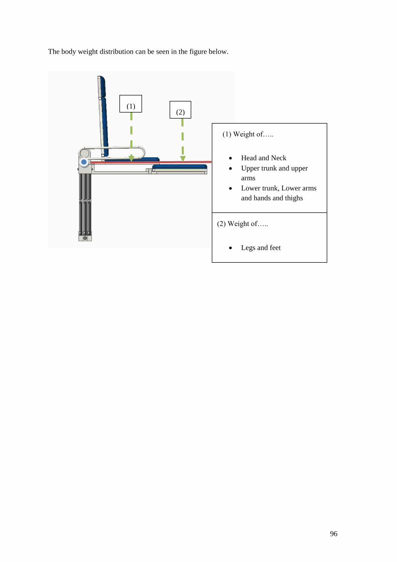
96
The body weight distribution can be seen in the figure below.
(1) Weight of…..
Head and Neck
Upper trunk and upper
arms
Lower trunk, Lower arms
and hands and thighs
(1)
(2) Weight of…..
Legs and feet
(2)

97
(1): This weight acting on the chair is a composition of three body parts. Worst case scenario is
assumed and this is that the back of the seat is completely upright. This means that the weight of
the head and neck and upper trunk are acting in positive clockwise direction rather than if the
back of seat was lying back, then they would act in counter-clockwise direction. It is also so
assumed that this weight is acting in the centre of the seat base
As can be read off the ISO 6875:2011 table, the combined mass of…
Head and neck = 10kg
Upper trunk and upper arms = 45kg
Lower trunk, Lower arms and hands and thighs = 55kg
Total mass = 110kg
Total weight = 1079.1 N
(2): It is assumed that this weight is acting through the centre of the fully extended footrest.
Also read off the ISO 6875:2011 table, the mass of…
Legs and feet = 25kg
Total weight = 245.25 N
Therefore the overall bending moment diagram can be seen below.

98
Calculating the bending moment about A:
( )( ) ( )( ) ( )( )
Putting the calculated bending moment into perspective, it is the equivalent of loading the end of
a metre stick with 77kg. This presents a large bending moment about point A. Now alterations in
the design will be discussed in order to lower the bending moment.
402.714 mm
435 mm
912.5 mm
1079.1 N 245.25 N
161.541 N
A
99
Possible Design Alterations to Reduce Bending Moment
There are three concepts in which can be used to reduce the bending moment acting at the scissor
lift. These are as listed…
1. Counter weight with suspension cables and pulley
2. Extra leg support
These concepts will now be analysed as to determine which performs greatest and is best suited to
the design.

100
Counter weight

101

102
Extra leg support
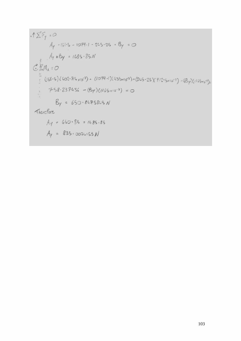
103

104
Discussion
From calculations, the author noted that the bending moment acting at the point of where the
dental chair is cantilevered was great as it amounted to 758.3N.m. Putting this in perspective it is
the equivalent of placing a 77kg mass on the end of a metre stick. Two possible solutions to try
and alleviate the bending moment were:
Adding the feature of a counter weight with the use of cables and a pulley
or
The addition of an extra leg support underneath the leg rest.
In regards to the counter weight, It was calculated that the additional mass needed to balance the
chair was 65.6kg. The concept would in theory work well, although there are a number of
problems with this solution. For one the wire cables impede access to the side of the chair. Also
the extra weight has further strain on both the scissor lift and the motor which will therefore
increase the power needed to raise and lower the chair. The second concept of adding an extra leg
under the foot rest also counteracted the bending moment transferring the load to the ground. It
was calculated that the force acting upon the leg was 650.8 N or in other words supporting the
mass of 66.34kg. This concept seemed to be most adequate as it did not add substantial weight to
the dental chair and having minimal effect on the power needed to raise the load. It was also the
most achievable design as it uses the concept of a walking aid crutch which is both light weight
and strong as most standard crutches are designed to take the weight of a 110kg person whilst
only weighing 10-12kg themselves.

105
Conclusion
In conclusion of this report the author gained valuable insight into various bending moment
solutions. Also the bending moment acting on the point at which the dental chair is cantilevered
was calculated. Various ways in which could try and alleviate this bending moment were then
investigated. The two concepts which were chosen to further analyse were adding the feature of a
counter weight with the use of cables and a pulley and the addition of an extra leg support
underneath the leg rest. These were then analysed first of all finding the weight needed to zero the
bending moment and then finding the force acting on the extra leg support. From these results it
was concluded that the use of the extra leg support would be most viable as it has the least amount
of impact of the scissor lift and the impact on the power needed to raise and lower the dental
chair.
Learning outcomes:
Searching, obtaining and interpreting ISO standards
Further insight into analysing cantilevered structures
Further insight into summarising forces and finding reactions
Practical application of bending moment analysis
Further insight into mechanical design

106
Appendix 3: Finite Element Analysis Report

107
Contents
1.0 Introduction ................................................................................................................ 108
2.0 Element Type ............................................................................................................. 109
3.0 Material Properties ..................................................................................................... 109
4.0 Loads and Boundary Constraints: ......................................................................... 110
5.0 Beam Sections ............................................................................................................ 114
5.0 Results ........................................................................................................................ 116
6.0 Conclusion and Discussion ........................................................................................ 119
List of Figures
Figure 1: Disabled Friendly Dental Chair ........................................................................ 108
Figure 2: Location of Applied Loads ............................................................................... 110
Figure 3: Plot of Nodes 381, 813 and 1245 ..................................................................... 111
Figure 4: Plot of Nodes 280, 712 and 1144 ..................................................................... 111
Figure 5: Plot of Nodes 1, 433 and 865 ........................................................................... 112
Figure 6: Plot of Nodes 114, 546 and 978 ....................................................................... 113
Figure 7: Beam Section for Cross Members .................................................................... 114
Figure 8: Beam Section for Pins ...................................................................................... 115
Figure 9: Basic Solution Controls .................................................................................... 116
Figure 10: Nonlinear Solution Controls ........................................................................... 116
Figure 11: Load vs Deflection Graph .............................................................................. 117
List of Tables
Table 1: Element Type ..................................................................................................... 109
Table 2: Material Properties............................................................................................. 109 Table 3: List of all Loads Applied ................................................................................... 110 Table 4: List of all Constraints Applied ........................................................................... 112 Table 5: Points for Figure 11 ........................................................................................... 118

108
1.0 Introduction
The following is a report on the Finite element analysis performed on a feature of the
author’s final design of a disabled friendly dental chair which is the author’s final year
project. The final design can be seen in figure 1.
The feature of the design in which is analysed is the scissor lift which will raise and lower
the dental chair. In order for the design to be satisfactory the scissor lift must be able to
raise and lower the weight of a patient and the self-weight of the actual chair without
failure. Failure in this case is the load at which the scissor lift will buckle. It is this
buckling load in which is going to be obtained during the finite element analysis. The
buckling load will then be compared to the weight of the chair and the weight of the
patient (obtained from ISO 6875:2011 Dentistry-Patient Chair). If the load from the chair
and patient is greater than the buckling load of the scissor lift then the design has not
satisfied ISO 6875:2011 and therefore the design will have to be revisited.
Figure 37: Disabled Friendly Dental Chair

109
2.0 Element Type
The element type used for this Non liner Buckling Analysis is the Beam189. As shown
below in table 1.
Table 6: Element Type
LIST ELEMENT TYPES FROM 1 TO 2 BY 1 ELEMENT TYPE 1 IS BEAM189 3-D 3-NODE BEAM KEYOPT( 1- 6)= 0 0 0 0 0 0 KEYOPT( 7-12)= 0 0 0 0 0 0 KEYOPT(13-18)= 0 0 0 0 0 0 CURRENT NODAL DOF SET IS UX UY UZ ROTX ROTY ROTZ THREE-DIMENSIONAL MODEL
3.0 Material Properties
The material properties used in this analysis are listed in Table 2, which is presented
below. These values were obtained from CES Edu-Pak.
Modulus of Elasticity 200GPa
Poisson’s ratio 0.285
Table 7: Material Properties
EVALUATE MATERIAL PROPERTIES FOR MATERIALS 1 TO 1 IN INCREMENTS OF 1 MATERIAL NUMBER = 1 EVALUATED AT TEMPERATURE OF 0.0000 EX = 0.20000E+12 NUXY = 0.28500 PRXY = 0.28500

110
4.0 Loads and Boundary Constraints:
Table 8: List of all Loads Applied
Table 3, given below, is a list of all loads applied to the scissor lift: LIST NODAL FORCES FOR SELECTED NODES 1 TO 1320 BY 1 CURRENTLY SELECTED NODAL LOAD SET= FX FY FZ MX MY MZ NODE LABEL REAL IMAG 280 FX -65307.1794 0.00000000 280 FY -75729.6000 0.00000000 280 FZ 200.000000 0.00000000 381 FX 65307.1794 0.00000000 381 FY -75729.6000 0.00000000 381 FZ 200.000000 0.00000000 712 FX -65307.1794 0.00000000 712 FY -75729.6000 0.00000000 712 FZ 200.000000 0.00000000 813 FX 65307.1794 0.00000000 813 FY -75729.6000 0.00000000 813 FZ 200.000000 0.00000000 1144 FX -65307.1794 0.00000000 1144 FY -75729.6000 0.00000000 1144 FZ 200.000000 0.00000000 1245 FX 65307.1794 0.00000000 1245 FY -75729.6000 0.00000000 1245 FZ 200.000000 0.00000000
Figure 2, shows the location of the nodes in which shows the position of the applied
loads. (Black background as to distinguish the lines clearer).
Figure 38: Location of Applied Loads

111
Figure 39: Plot of Nodes 381, 813 and 1245
Figure 40: Plot of Nodes 280, 712 and 1144

112
Below is list of all constraints applied to the Scissor lift:
Table 9: List of all Constraints Applied
LIST CONSTRAINTS FOR SELECTED NODES 1 TO 1320 BY 1 CURRENTLY SELECTED DOF SET= UX UY UZ ROTX ROTY ROTZ NODE LABEL REAL IMAG 1 UX 0.00000000 0.00000000 1 UY 0.00000000 0.00000000 1 UZ 0.00000000 0.00000000 114 UX 0.00000000 0.00000000 114 UY 0.00000000 0.00000000 114 UZ 0.00000000 0.00000000 433 UX 0.00000000 0.00000000 433 UY 0.00000000 0.00000000 433 UZ 0.00000000 0.00000000 546 UX 0.00000000 0.00000000 546 UY 0.00000000 0.00000000 546 UZ 0.00000000 0.00000000 865 UX 0.00000000 0.00000000 865 UY 0.00000000 0.00000000 865 UZ 0.00000000 0.00000000 978 UX 0.00000000 0.00000000 978 UY 0.00000000 0.00000000 978 UZ 0.00000000 0.00000000
Figure 3 shows the location of area 75, while Figure 4 presents the location of area 69.
Figure 41: Plot of Nodes 1, 433 and 865
.1

113
Figure 42: Plot of Nodes 114, 546 and 978

114
5.0 Beam Sections
A screen shot of the beam sections used in the scissor lift cross members can be seen be
in Figure 7.
Figure 43: Beam Section for Cross Members

115
A screen shot of the beam section used to represent the pins can be seen in Figure 8.
Figure 44: Beam Section for Pins
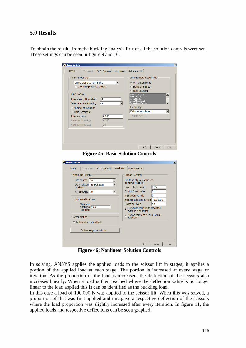
116
5.0 Results
To obtain the results from the buckling analysis first of all the solution controls were set.
These settings can be seen in figure 9 and 10.
Figure 45: Basic Solution Controls
Figure 46: Nonlinear Solution Controls
In solving, ANSYS applies the applied loads to the scissor lift in stages; it applies a
portion of the applied load at each stage. The portion is increased at every stage or
iteration. As the proportion of the load is increased, the deflection of the scissors also
increases linearly. When a load is then reached where the deflection value is no longer
linear to the load applied this is can be identified as the buckling load.
In this case a load of 100,000 N was applied to the scissor lift. When this was solved, a
proportion of this was first applied and this gave a respective deflection of the scissors
where the load proportion was slightly increased after every iteration. In figure 11, the
applied loads and respective deflections can be seen graphed.

117
Figure 47: Load vs Deflection Graph Deflection (m) * 1000
Load (N)
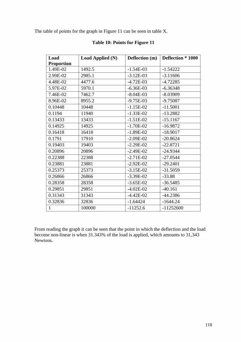
118
The table of points for the graph in Figure 11 can be seen in table X.
Table 10: Points for Figure 11
Load
Proportion
Load Applied (N) Deflection (m) Deflection * 1000
1.49E-02 1492.5 -1.54E-03 -1.54222
2.99E-02 2985.1 -3.12E-03 -3.11606
4.48E-02 4477.6 -4.72E-03 -4.72285
5.97E-02 5970.1 -6.36E-03 -6.36348
7.46E-02 7462.7 -8.04E-03 -8.03909
8.96E-02 8955.2 -9.75E-03 -9.75087
0.10448 10448 -1.15E-02 -11.5001
0.1194 11940 -1.33E-02 -13.2882
0.13433 13433 -1.51E-02 -15.1167
0.14925 14925 -1.70E-02 -16.9872
0.16418 16418 -1.89E-02 -18.9017
0.1791 17910 -2.09E-02 -20.8624
0.19403 19403 -2.29E-02 -22.8721
0.20896 20896 -2.49E-02 -24.9344
0.22388 22388 -2.71E-02 -27.0544
0.23881 23881 -2.92E-02 -29.2401
0.25373 25373 -3.15E-02 -31.5059
0.26866 26866 -3.39E-02 -33.88
0.28358 28358 -3.65E-02 -36.5485
0.29851 29851 -4.02E-02 -40.161
0.31343 31343 -4.42E-02 -44.2386
0.32836 32836 -1.64424 -1644.24
1 100000 -11252.6 -11252600
From reading the graph it can be seen that the point in which the deflection and the load
become non-linear is when 31.343% of the load is applied, which amounts to 31,343
Newtons.

119
6.0 Conclusion and Discussion
In conclusion the scissor lift was modelled using beam elements. Loads were applied and
then a non-linear buckling analysis was conducted. The Buckling analysis determined that
the scissor lift will buckle under the load of 31,342 N. Putting this in perspective is the
weight of 3,194.9 kg. This means that the designed scissor lift complies with ISO
6875:2011 Dentistry-Patient Chair. Although considering the scissor lift only needs to bear
the weight of 1485.9 N (151.466 kg) the scissor lift designed by the author may have to be
revisited as the bucking analysis results show it is over designed.

120
Appendix 4: ISO Standards for a Dental Chair

121

122

123

124

125

126
127

128

129

130

131

132

133

134
135

136

137
Appendix 5: Engineering Drawings

138

139
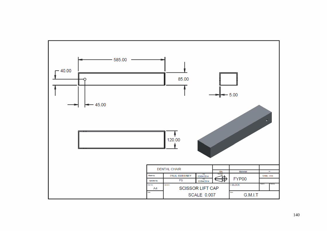
140
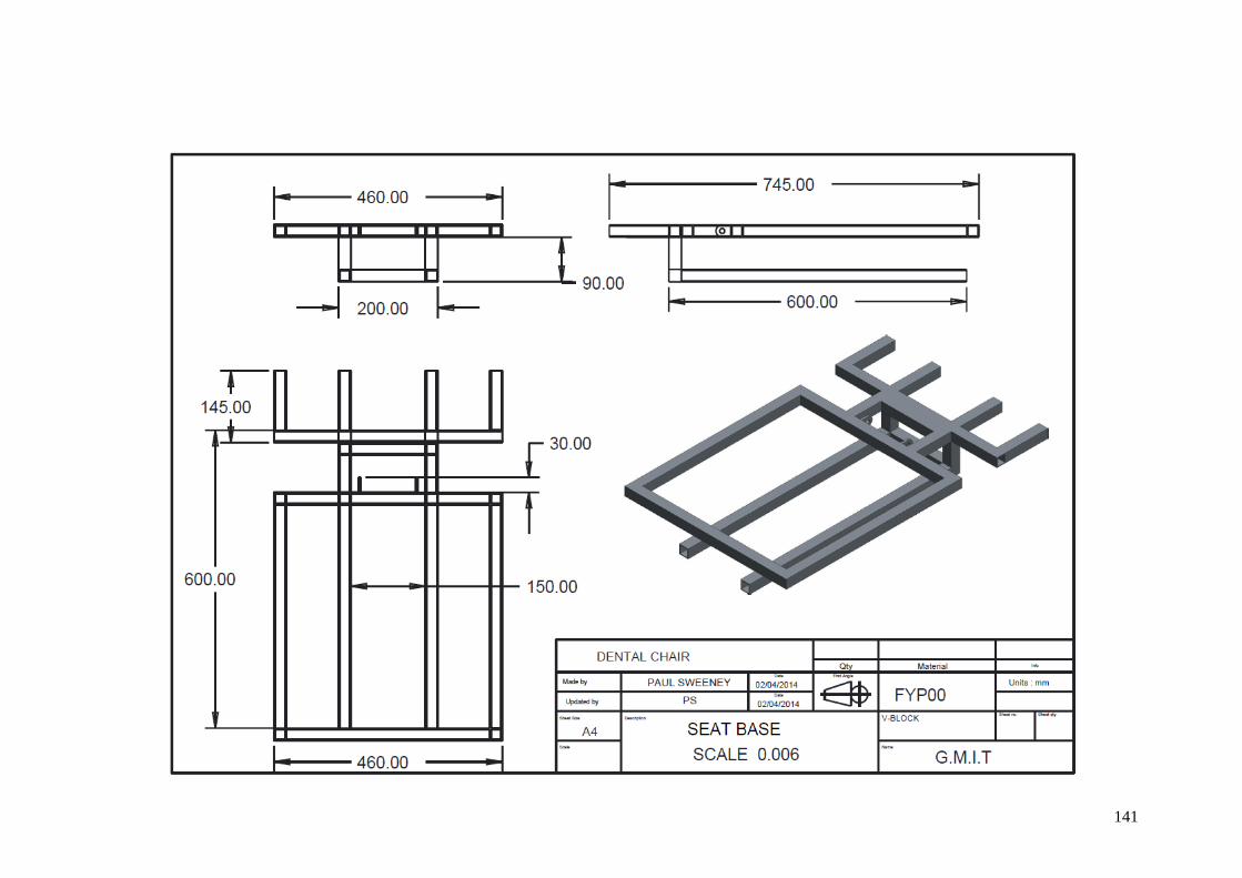
141

142

143

144
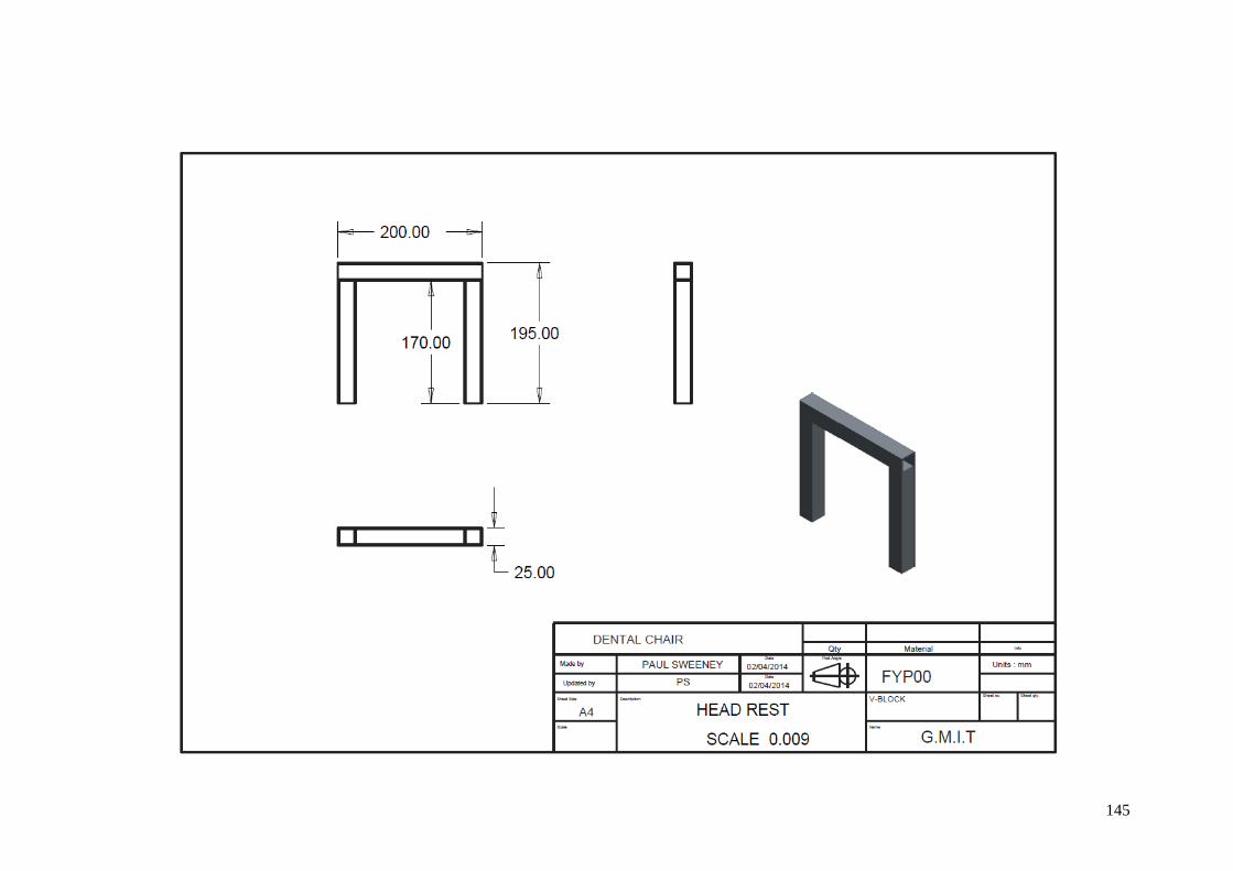
145

146

147

148

149
References
[1]: (2007). Product Development: A Structured Approach to Design and Manufacture. Butterworth-Heinemann.
http://0-site.ebrary.com.library.gmit.ie/lib/gmit/docDetail.action?docID=10204288
Access date: 27 Nov 2013
[2]: America, I.D.o. (2014). Course: 45856 -- Industrial Design. In.
http://learnonline.gmit.ie/pluginfile.php/19663/mod_resource/content/4/S1_IDSA_description%20of%20industrial%20design.pdf
Access date: 7 Jan 2014
[3]: Belmont. (2014). Pro-II_Eng.pdf (application/pdf Object). In.
http://www.belmont.fr/doc/dentaire/Pro-II_Eng.pdf
Access date: 8 Jan 2014
[4]: Central Statistics Office. (2014). National,Disability,Survey,2006,First,Results,full,report.pdf (application/pdf Object). In, Vol. 07/01/2014.
http://www.cso.ie/en/media/csoie/releasespublications/documents/otherreleases/nationaldisability/National,Disability,Survey,2006,First,Results,full,report.pdf
Access date: 7 Jan 2014
[5]: Cooper, R.G. (2008). Perspective: The Stage‐Gate® Idea‐to‐Launch Process—Update, What's New, and NexGen Systems. Journal of Product Innovation Management 25(3), 213-232.
http://qd5rw8vx4w.search.serialssolutions.com/?ctx_ver=Z39.88-2004&ctx_enc=info%3Aofi%2Fenc%3AUTF-8&rfr_id=info:sid/summon.serialssolutions.com&rft_val_fmt=info:ofi/fmt:kev:mtx:journal&rft.genre=article&rft.atitle=Perspective&rft.jtitle=The+journal+of+product+innovation+management&rft.au=Cooper%2C+Robert+G&rft.date=2008&rft.pub=Blackwell+Publishing&rft.issn=0737-6782&rft.eissn=1540-5885&rft.volume=25&rft.issue=3&rft.spage=213&rft.epage=232&rft.externalDocID=561627126¶mdict=en-US
Access date: 27 Nov 2013
[6]: Department of Health and Children, I. (2014). oral_health_promotion.pdf (application/pdf Object). In.
http://www.dohc.ie/other_health_issues/dental_research/oral_health_promotion.pdf?direct=1
Access date: 8 Jan 2014
[7]: Department of Physical Therapy, I.C., University of Rochester Campus, Rochester, NY, USA,. (2003). Three-dimensional shoulder kinematics during a pressure relief technique and wheelchair transfer1. 84(9), 1293–1300.
http://www.sciencedirect.com/science/article/pii/S0003999303002600
Access date: 7 Jan 2014

150
[8]: Hippel, E.V. (2014). Source of Novel Product Concepts.pdf (application/pdf Object). In.: of Novel Product Concepts.pdf (application/pdf Object).
https://faculty.fuqua.duke.edu/~moorman/GeneralMills/Section3/Section3Documents/Source%20of%20Novel%20Product%20Concepts.pdf
Access date: 7 Jan 2014
[9]: Kwan, S.Y.L., Institute, L.D., Petersen, P.E., Organization, W.H., Pine, C.M., Liverpool, U.o., Borutta, A., & Jena, F.-S.U.o. (2005). Health-promoting schools: an opportunity for oral health promotion. Bull World Health Organ 83(9), 677-685.
http://www.scielosp.org/pdf/bwho/v83n9/v83n9a13.pdf
Access date: 10 Jan 2014
[10]: Labana Medical Store. (2014). Kavo 1058 Compact Dental Chair Package. In.
http://labanamedicalstore.com/products.php?product=Kavo-1058-Compact-Dental-Chair-Package
Access date: 8 Jan 2014
[11]: Planmeca. (2014). Planmeca Chair. In.
http://www.planmeca.com/Dental-units/Planmeca-Chair/
Access date: 8 Jan 2014
[12]: Pugh, S. (1991). Total Design: Integrated Methods For Successful Product Engineering. United Kingdom, London: Addison-Wesley Publishers Ltd.
[13]: STUCK, L. (1892). DENTAL CHAIR. In.: Google Patents.
[14]: trace.wisc.edu. (2014). ADAAG Figure A6. In.
http://trace.wisc.edu/docs/adaag_only/figa6.html
Access date: 9 Jan 2014
[15]: Ulrich, K.T., & Eppinger, S.D. (2004). Product design and development. Boston: McGraw-Hill/Irwin.
http://library.gmit.ie/record=b1112617
Access date: 27 Nov 2013
[16]: University of Pittsburgh. (2014). Lower Extremity Weight bearing During Three Lateral Level Wheelchair Transfer Techniques. In.
http://web.resna.org/library/conference_2010/Wheeled%20Mobility/Student%20Papers/KankipatiP.html
Access date: 9 Jan 2014
[17]: World Health Organization. (2013). WHO | Disabilities. WHO.
http://www.who.int/topics/disabilities/en/
Access date: 7 Jan 2014