the design of guideways for prt systems · web viewthe design of guideways for personal rapid...
TRANSCRIPT
The Design of Guideways for Personal Rapid Transit Systems
J. Edward Anderson
AbstractPRT guideways are analyzed based on a result of prior dynamic analysis of vehicles moving
across flexible spans in which it was found that the shorter the headway between vehicles the smaller is the difference between dynamic and static deflections, and that in the limit of zero nose-to-tail spac-ing between vehicles the static and dynamic deflections are the same. The analysis is applicable to systems in which small vehicles operated at a full-range of speeds including speeds applicable to inter-city travel. The results found are:
The load-supporting weight of the guideway is directly proportional to the pay load. If a guideway of given depth and span is stressed to its design limit, the ratio of guideway
weight to payload is more than 50% higher with simply-supported spans than if the guide-way is clamped to the support posts.
The guideway width needed to resist wind or earthquake loads is less than the depth. The limit speed for acceptable ride comfort increases with span because longer spans mean
lower crossing frequencies, and lower frequencies usually imply higher tolerable amplitudes of vertical acceleration.
For a given design stress, beam depth and span, the limit speed is higher for simply-sup-ported guideways than for clamped guideways, however at a heavy price in guideway weight.
To minimize guideway weight and hence cost, the vehicles must cruise at a crossing fre-quency higher than the fundamental natural frequency of the fully loaded guideway, but generally lower than the fundamental natural frequency of the empty guideway. This prac-tice will be satisfactory if vehicles operating at less than maximum throughput are spaced randomly, as is the case if the control system is asynchronous. By use of active control, crossing frequencies that may be a problem can be avoided. This practice is new for guide-way transit, but has been common for decades in the operation of large turbines, where the phenomenon is the same and substantial cost savings result.
Introduction
An issue that has been long debated among Automated Guideway Transit (AGT) workers is the relationship between guideway weight and hence cost and the weight of the load carried. A full treatment of this issue requires dynamic analysis of vehicles moving across flexible spans in both straight and curved sections. Work done on this problem in the mid 1970s [Snyder, Wormley and Richardson (SWR), 1975] has made it possible to obtain useful information from an analytical treatment. The pur-pose of this paper is to develop the relationship between acceptable guideway weight, depth, weight of the load carried, and other parameters of interest for a range of span lengths and speeds.
Consider a guideway supported by posts spaced at a distance on which vehicles run at speed at an arbitrary spacing. The largest stresses and deflections occur when the vehicles are all fully loaded and operating at the minimum spacing. Elementary beam analysis shows that the deflec-
tion of a simply supported beam under a uniform load is five time the deflection of the same beam clamped at both ends under the same uniform load. The maximum bending stress in a simply supported beam is 50% higher than the maximum bending stress in a clamped beam under the same load. For these reasons, we have specified that the beam be rigidly attached, i.e., clamped to the support posts. Because thermal expansion joints are needed, they should be placed close to one of the points of zero bending moment in a beam under uniform load, which are at 21.1% from the ends of the span. Here the beam under uniform load takes only shear. The recommendations to clamp the beam and place the joints at a point of zero bending moment were first stated by The Aerospace Corporation [Irving, et al, 1978]. To understand the differences, in this paper simply-supported guideways are compared with guideways clamped to the posts.
Under a U.S. DOT grant, SWR simulated the motion of vehicles of a variety of sizes at a va-riety of headways over guideways having a variety of span lengths. They calculated deflections and stresses and presented the results in a very useful dimensionless form. They found that as the headway decreases to a smaller and smaller fraction of the span, the ratio of dynamic to static deflection (with vehicles in the static case positioned to give the greatest deflection) decreases. The deflection would be greater if the vehicles were spaced nose to tail, and in that case the ratio of dynamic to static deflection is unity because the beam experiences the same uniform load whether or not the vehicles are moving. I analyze this situation in my textbook [Anderson, 1978] and concluded, with the verbal concurrence of Professors Wormley and Richardson, that if the beam is designed for fully loaded vehicles spaced nose to tail over the whole guideway, the design stress will not be exceeded in any circumstance. Thus the easiest design load determines the design of the guideway.
Now consider a person riding a vehicle at a given speed. As the speed increases, the ampli-tude of the oscillatory vertical acceleration due to bending of the guideway increases until at some speed, a limit speed, the ride-comfort acceleration is reached. By considering the structural equations for the bending stress and deflection of beams, and the International Standards Organization (ISO) ride-comfort standard, the maximum permissible speed for any guideway can be found. Based on previous analysis of steel vs. concrete, all the following analysis relates to steel guideways.
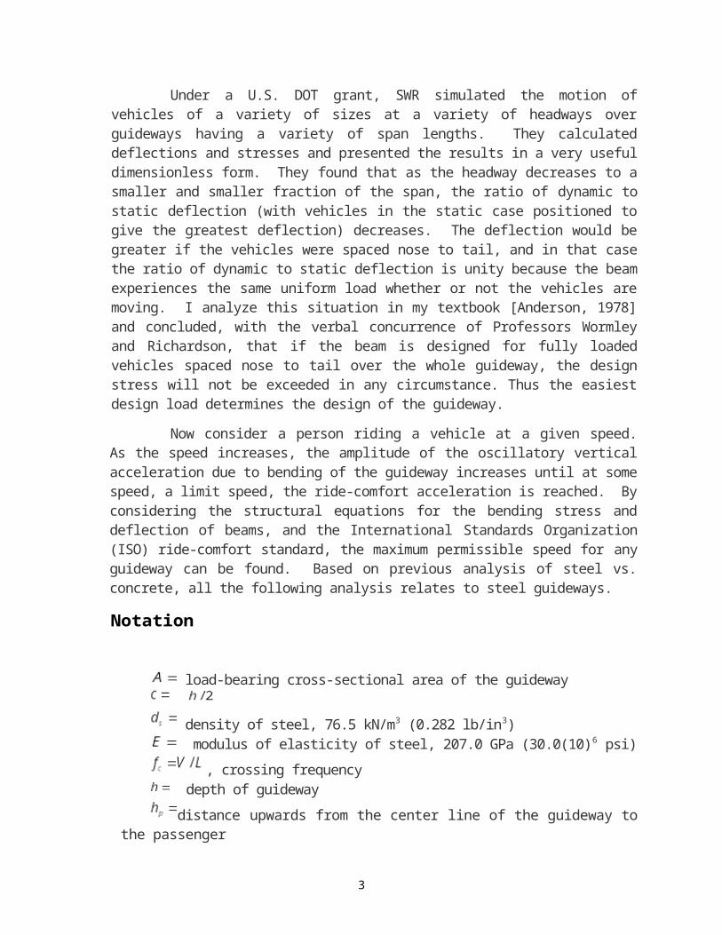
Notation
load-bearing cross-sectional area of the guideway
density of steel, 76.5 kN/m3 (0.282 lb/in3) modulus of elasticity of steel, 207.0 GPa (30.0(10)6 psi)
, crossing frequency depth of guideway
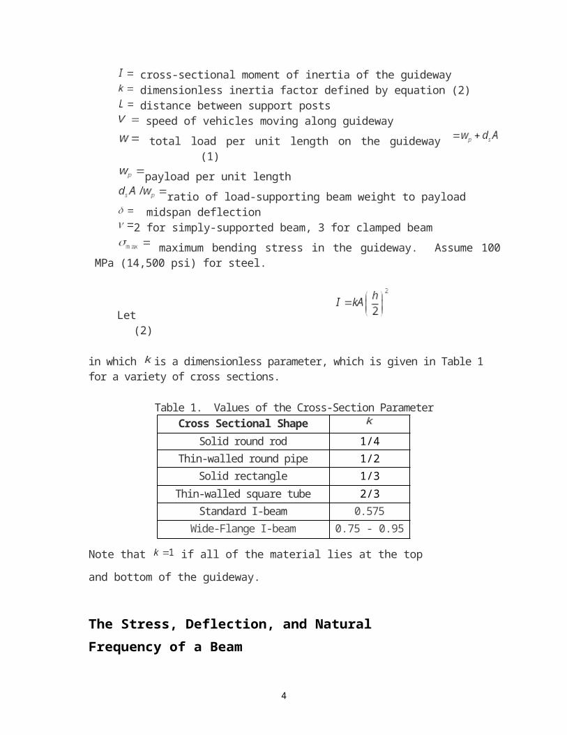
distance upwards from the center line of the guideway to the passenger cross-sectional moment of inertia of the guideway dimensionless inertia factor defined by equation (2) distance between support posts speed of vehicles moving along guideway
total load per unit length on the guideway (1)
2
payload per unit length
ratio of load-supporting beam weight to payload midspan deflection2 for simply-supported beam, 3 for clamped beam
maximum bending stress in the guideway. Assume 100 MPa (14,500 psi) for steel.
Let (2)
in which is a dimensionless parameter, which is given in Table 1 for a variety of cross sections.
Table 1. Values of the Cross-Section ParameterCross Sectional Shape
Solid round rod 1/4Thin-walled round pipe 1/2
Solid rectangle 1/3Thin-walled square tube 2/3
Standard I-beam 0.575Wide-Flange I-beam 0.75 - 0.95
Note that if all of the material lies at the top and bottom of the guideway.
The Stress, Deflection, and Natural Frequency of a Beam
Consider a beam of length , depth h, and moment of inertia I subject to a uniform load w. From textbooks on structures and vibrations, one finds the following formulae:
For the maximum bending moment
Simply-supported beam
(3)
Beam clamped at both ends
(4)
3
For the maximum bending stress
Simply-supported beam
(5)
Beam clamped at both ends
(6)
For the maximum deflection
Simply-supported beam (equation (5) substituted)
(7)
Beam clamped at both ends (equation (6) substituted)
(8)
So, for given and given design stress, the clamped beam deflects 30% as much as the simply-supported beam, whereas for a given load it deflects 20% as much.
For the fundamental natural frequency
Simply-supported beam (first then third forms of equation (7) substituted)
(9)
Beam clamped at both ends (first then third forms of equation (8) substituted)
4
(10)
Thus, for given deflection, the natural frequency of the clamped beam is 0.1817/0.1792 = 1.014 or 1.4% higher than for the simply-supported beam, but for the same static design stress the natural frequency of the clamped beam is 1.851 times higher.
In equations (9) and (10) the deflection is taken from equations (7) and (8), respectively, with the maximum stress equal to the design stress for the material used. If the beam is not loaded, the maximum stress will of course be less. It is convenient to determine the unloaded natural frequency of the beam by sub-
stituting in the first form of equations (9) and (10) the quantity for Then, using the formula for area moment of inertia given by equation (2), the unloaded first-mode natural frequencies for the simply-supported and clamped beams, respectively, are
(11)
As shown by SWR, the unloaded natural frequency appears in the exact equations for analysis of the dynam-ics of moving vehicles crossing flexible spans, so it is of interest.
The Critical Speed
The critical speed occurs when the crossing frequency V/L is equal to the loaded-guideway natural fre-
quency , i.e., when . From equations (9) and (10) the formulae for Vcr for fully-loaded simply-supported and clamped beams, respectively, in terms of either the maximum deflection or the specified maxi-mum bending stress, are
. (12)
Because the deflection is proportional to the maximum stress multiplied by span squared, the form containing the maximum stress is independent of the span length.
The Ratio of Beam Weight to Pay Load The ratio of beam weight to pay load is
5
(13)
Substituting equations (1) and (2) into equations (5) and (6), we have
(14)
in which for a simply supported beam and for a beam clamped at both ends. Thus,
(15)
in which
(16)
Equations (15) and (16) show that the beam weight is directly proportional to the maximum live load
the beam can carry, and depends on the end conditions, the cross sectional shape factor k, the ratio
and the material property Note that the factor is 50% larger for a clamped beam that for a simply-supported beam. From the form of equation (15), we see that for given values of the cross-sec-
tional shape factor k, the ratio and the material property the weight of the simply-sup-ported beam is more than that of the clamped beam by a factor more than 1.5. By clamping the beam, it is possible to reduce its depth somewhat and still keep the beam weight less than that of the simply-sup-ported beam.
Lateral Loading
It is necessary to determine if the guideway designed to withstand vertical loads will withstand lateral wind or earthquake loads. To do so, consider an example in which a guideway clamped to the support posts is required to support 9-ft-long, 1600 lb gross-weight vehicles, figures that I have found
from an actual design. For this case 1600/9 = 177.8 lb/ft (2594 N/m). Let h = 1 m and L = 27 m. From Table 1 assume k = 0.6. Then, from equation (16),
6
so, using equation (1) and (15)
Assume that the wind load per unit length is equal to w. Then
in which kg/m3 is density of standard air, I assume that the drag coefficient , and h = 1 m. A drag coefficient of unity for the side of the guideway can be obtained if the guideway is covered with a curve radius on the top and bottom edges of at least h/6 [Scruton and Rogers, 1971]. Thus, the
lateral wind speed that will result in a lateral force per unit length of w is = 71 m/s = 255 km/hr = 158 mph. Since this wind speed is well in excess of any code for structural design, the guideway width can be less than h.
Earthquake loads are specified in terms of lateral acceleration, i.e., as an inertia load. It is inter-esting to note that in a standard textbook on earthquake engineering written in the 1960s, it is stated that the maximum horizontal acceleration measured in an earthquake was 0.25 g. However, in a speech be-fore the Society of American Military Engineers a few months after the 1994 Los Angeles earthquake, the director of reconstruction of the Los Angeles freeways stated that earthquake accelerations up to 1.6 g's had been measured. This discrepancy may be the reason that structures in California and Kobe, Japan supposedly designed for earthquakes collapsed. If an earthquake occurs when the guideway is empty or lightly loaded, the horizontal inertial load would be the earthquake acceleration in g,s multi-
plied by the empty guideway weight But the ratio of the load for which a guideway of depth h
would be designed to the empty guideway weight is, from equation (15), , which in this ex-ample is 6.46. Thus, if the guideway width were the same as the depth, the empty guideway would be able to withstand an earthquake load of 6.46 g's, which is 6.46/1.6 = 4.0 times the maximum known re-quirement. Since the guideway width to withstand the maximum wind loading is less than h, the factor of safety is somewhat less, but still substantial. It is clear that the lighter the guideway for the load that must be carried, the more easily it can withstand an earthquake load.
Accelerations Experienced by Passengers
Consider a person riding in one of the vehicles moving along the guideway at a constant speed V. Because the beam deflects, the passenger moves up and down as the vehicle advances. The beams could be cambered at greater expense so that they would be flat at an average loading, but camber is not considered here. The vertical acceleration of the moving passenger is
7
(17)
in which M(x) is the bending moment in the beam. For simply-supported and clamped beams under the uni-form load w, structures textbooks show, respectively, that
(18)
Substituting where t is the time variable, in which is the crossing frequency.
Then, substituting equations (18) into equation (17), and noting that the time-varying portion of is in-
dependent of end conditions, we have for the time-varying portion of
(19)
The vertical acceleration is not the only acceleration felt by the passengers. Because of the varying slope of the beam, the passengers will be rocked back and forth due to variation in slope as the vehicles
moves from post to post. If is the distance of the midsection of the passenger from the centerline of the
guideway, the fore-aft component of acceleration is in which is the slope of the beam, dy/dx,
and is the second time derivative of the slope. Thus
8
(20)
in which it is indicated that, since hp /L≪1, comparing with equation (19) we can assume that the total time-varying acceleration is the vertical acceleration, i.e.,
(21)
in which has been substituted. The function in brackets in equation (21) has a maximum value of
1/4th in the span interval and an average value of 1/6th. Therefore, the acceleration varies from the mean value up to a peak of
(22)
If we substitute from equation (7) and equation (8) respectively for the term we see that, in terms of given values of design stress, L and h, the peak amplitude of acceleration for the simply-supported and clamped beams may be written, respectively, in the two forms
(23)
Thus, for a given maximum stress, speed, and beam depth, the peak acceleration experienced with the clamped beam is 1.5 times the peak acceleration experienced with the simply supported beam. In this case the clamped beam is lighter than the simply-supported beam. But, from equation (22), for given gross weight per unit length, beam dimensions, span length, and speed, the peak acceleration is independent of the type of beam support.
Since the peak comfort acceleration is a function of frequency, the first form of equations (23) will be
useful when in the next section we solve for the limit frequency at which the peak acceleration reaches
the maximum tolerable value, from which the limit speed is The second form of equation (23)
is useful to observe that increases as the square of the speed.
Some Design Comparisons
9
Equation (22) applies to both simply-supported and clamped beams. We see that, if the total load and beam properties are the same, the maximum acceleration, and hence the limit speed, is independent of the beam end conditions even though the maximum deflection of the simply-supported beam is five times that of the clamped beam. The important difference is, however, not in the equations for deflection, but in the equations for the bending moment, in which the only difference is a constant term. The addition of a constant term in the moment equation for a clamped beam means that a constant vertical acceleration is superimposed if the beam is clamped, but this is equivalent to changing gravity by a small amount and does not contribute to discomfort.
From equations (7) and (8), we see that, for a given load, the clamped beam deflects 20% as much as the simply-supported beam; however, for a given maximum stress the clamped beam deflects 30% as much as the simply-supported beam. The ratio is 1.5. To conserve material and hence cost, it is desirable to design
each beam to the same maximum bending stress. Hence, if h and L are fixed, equations (23) shows
that is proportional to and is 1.5 times as much for a clamped beam as for a simply-supported beam.
Thus, for a given and given is higher for a simply-supported beam than for a clamped beam
by a factor of But, from equations (15) and (16), for a given live load, in an acceptable range of speeds, with the same design stress, h, L, and beam geometry, the clamped beam is lighter by a fac-tor larger than 1.5.
Consider a typical example in which the material is steel with an allowable bending stress of 100 MPa (14,500 psi). It is common today to use A36 steel for structural purposes. According to the American Institute of Steel Construction Code, it has an allowable bending stress of 22,000 psi (152 MPa). The use of a lower design stress allows for long life, fatigue, temperature variations, and irregularities that are invariably
introduced during fabrication. Let and Then, for a simply-supported beam,
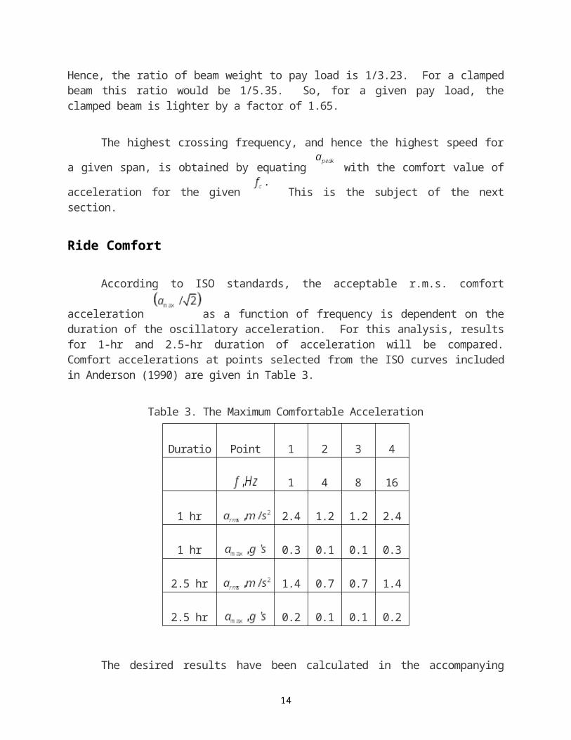
Hence, the ratio of beam weight to pay load is 1/3.23. For a clamped beam this ratio would be 1/5.35. So, for a given pay load, the clamped beam is lighter by a factor of 1.65.
The highest crossing frequency, and hence the highest speed for a given span, is obtained by equat-
ing with the comfort value of acceleration for the given This is the subject of the next section.
Ride Comfort
10
According to ISO standards, the acceptable r.m.s. comfort acceleration as a function of frequency is dependent on the duration of the oscillatory acceleration. For this analysis, results for 1-hr and 2.5-hr duration of acceleration will be compared. Comfort accelerations at points selected from the ISO curves included in Anderson (1990) are given in Table 3.
Table 3. The Maximum Comfortable Acceleration
Duration Point No. 1 2 3 4
1 4 8 16
1 hr 2.45 1.20 1.20 2.45
1 hr 0.353 0.173 0.173 0.353
2.5 hr 1.45 0.71 0.71 1.45
2.5 hr 0.209 0.102 0.102 0.209
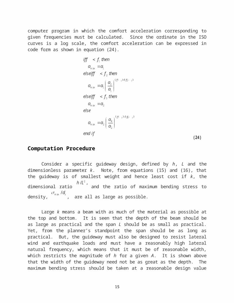
The desired results have been calculated in the accompanying computer program in which the com-fort acceleration corresponding to given frequencies must be calculated. Since the ordinate in the ISO curves is a log scale, the comfort acceleration can be expressed in code form as shown in equation (24).
(24)
11
Computation Procedure
Consider a specific guideway design, defined by h, L and the dimensionless parameter k. Note, from equations (15) and (16), that the guideway is of smallest weight and hence least cost if k, the dimen-
sional ratio and the ratio of maximum bending stress to density, , are all as large as possi-ble.
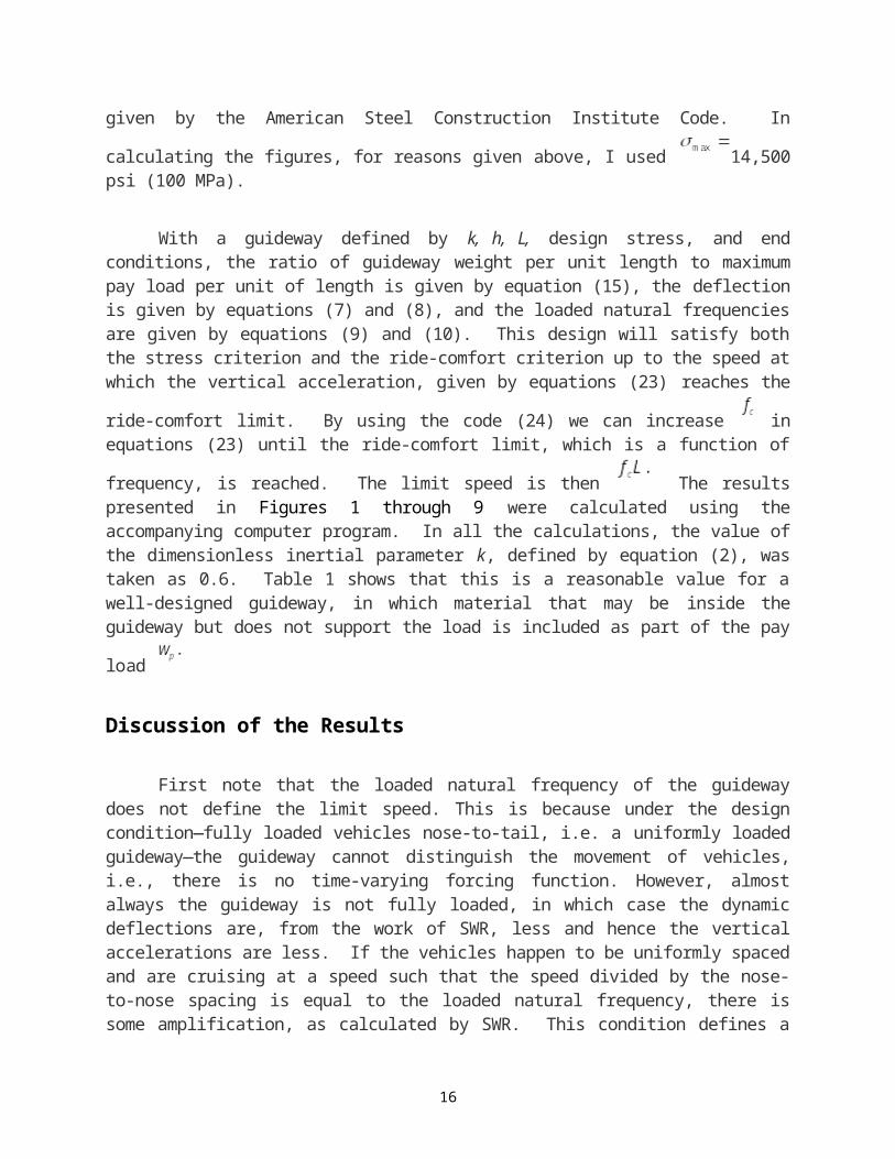
Large k means a beam with as much of the material as possible at the top and bottom. It is seen that the depth of the beam should be as large as practical and the span L should be as small as practical. Yet, from the planner’s standpoint the span should be as long as practical. But, the guideway must also be designed to resist lateral wind and earthquake loads and must have a reasonably high lateral natural frequency, which means that it must be of reasonable width, which restricts the magnitude of h for a given A. It is shown above that the width of the guideway need not be as great as the depth. The maximum bending stress should be taken at a reasonable design value given by the American Steel Construction Institute Code. In calculating
the figures, for reasons given above, I used 14,500 psi (100 MPa).
With a guideway defined by k, h, L, design stress, and end conditions, the ratio of guideway weight per unit length to maximum pay load per unit of length is given by equation (15), the deflection is given by equations (7) and (8), and the loaded natural frequencies are given by equations (9) and (10). This design will satisfy both the stress criterion and the ride-comfort criterion up to the speed at which the vertical accelera-
tion, given by equations (23) reaches the ride-comfort limit. By using the code (24) we can increase in equations (23) until the ride-comfort limit, which is a function of frequency, is reached. The limit speed is
then The results presented in Figures 1 through 9 were calculated using the accompanying computer program. In all the calculations, the value of the dimensionless inertial parameter k, defined by equation (2), was taken as 0.6. Table 1 shows that this is a reasonable value for a well-designed guideway, in which mate-
rial that may be inside the guideway but does not support the load is included as part of the pay load
Discussion of the Results
First note that the loaded natural frequency of the guideway does not define the limit speed. This is because under the design condition—fully loaded vehicles nose-to-tail, i.e. a uniformly loaded guideway—the guideway cannot distinguish the movement of vehicles, i.e., there is no time-varying forcing function. However, almost always the guideway is not fully loaded, in which case the dynamic deflections are, from the work of SWR, less and hence the vertical accelerations are less. If the vehicles happen to be uniformly spaced and are cruising at a speed such that the speed divided by the nose-to-nose spacing is equal to the loaded natural frequency, there is some amplification, as calculated by SWR. This condition defines a speed that can be avoided. Because the control concept recommended by the author [Anderson, 1997] is asynchro-nous, the vehicles will be randomly spaced down to a set minimum. This is similar to the well-known mili-tary situation in which soldiers are ordered to break step when walking across a bridge. Forcing functions out
12
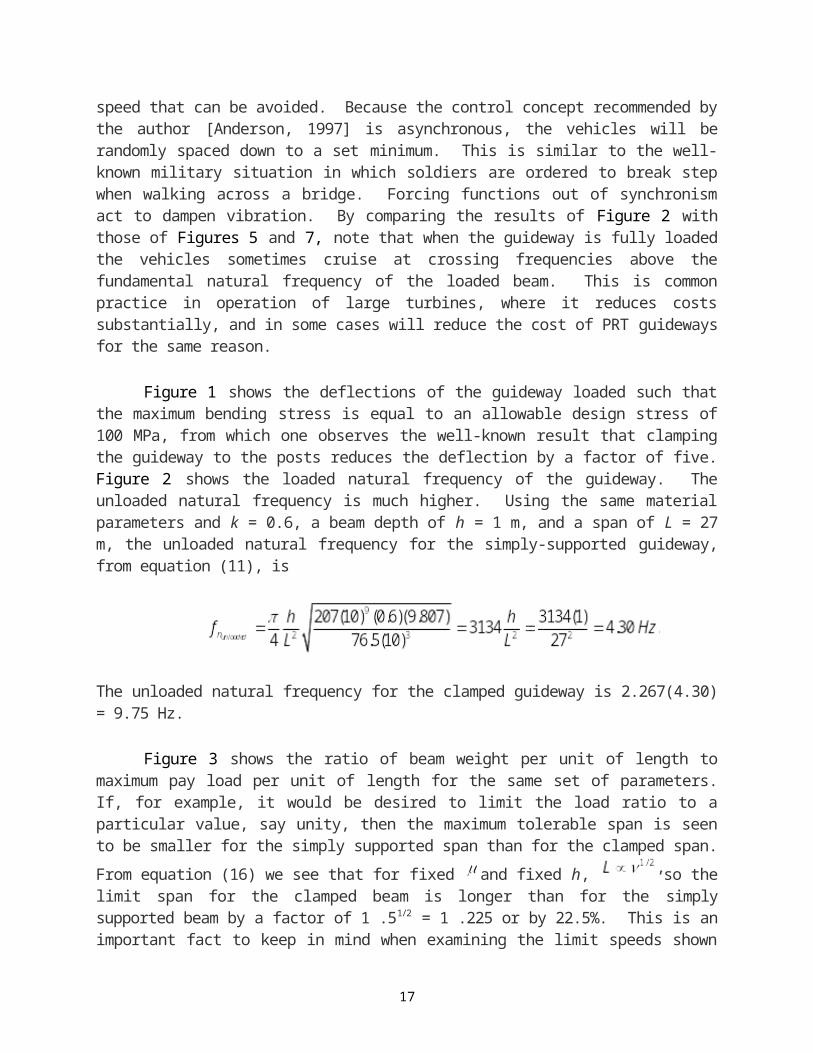
of synchronism act to dampen vibration. By comparing the results of Figure 2 with those of Figures 5 and 7, note that when the guideway is fully loaded the vehicles sometimes cruise at crossing frequencies above the fundamental natural frequency of the loaded beam. This is common practice in operation of large turbines, where it reduces costs substantially, and in some cases will reduce the cost of PRT guideways for the same reason.
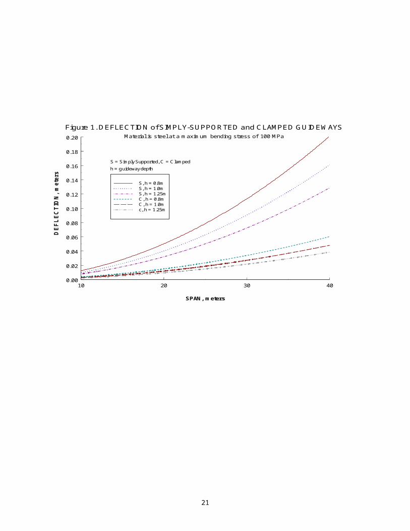
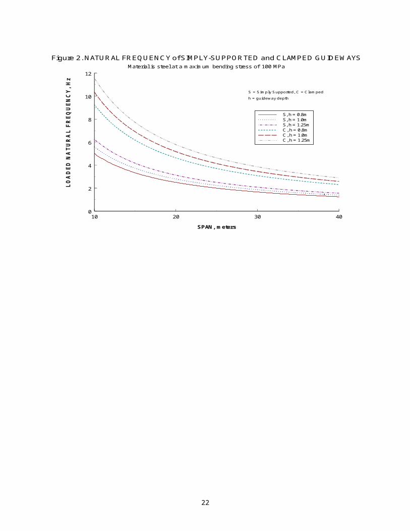
Figure 1 shows the deflections of the guideway loaded such that the maximum bending stress is equal to an allowable design stress of 100 MPa, from which one observes the well-known result that clamp-ing the guideway to the posts reduces the deflection by a factor of five. Figure 2 shows the loaded natural frequency of the guideway. The unloaded natural frequency is much higher. Using the same material pa-rameters and k = 0.6, a beam depth of h = 1 m, and a span of L = 27 m, the unloaded natural frequency for the simply-supported guideway, from equation (11), is
The unloaded natural frequency for the clamped guideway is 2.267(4.30) = 9.75 Hz.
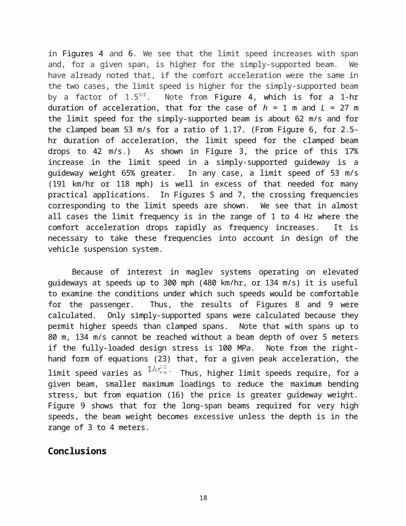
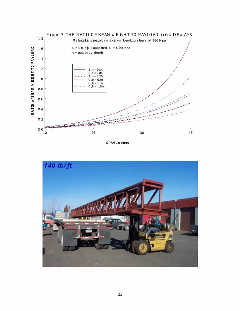
Figure 3 shows the ratio of beam weight per unit of length to maximum pay load per unit of length for the same set of parameters. If, for example, it would be desired to limit the load ratio to a particular value, say unity, then the maximum tolerable span is seen to be smaller for the simply supported span than for the
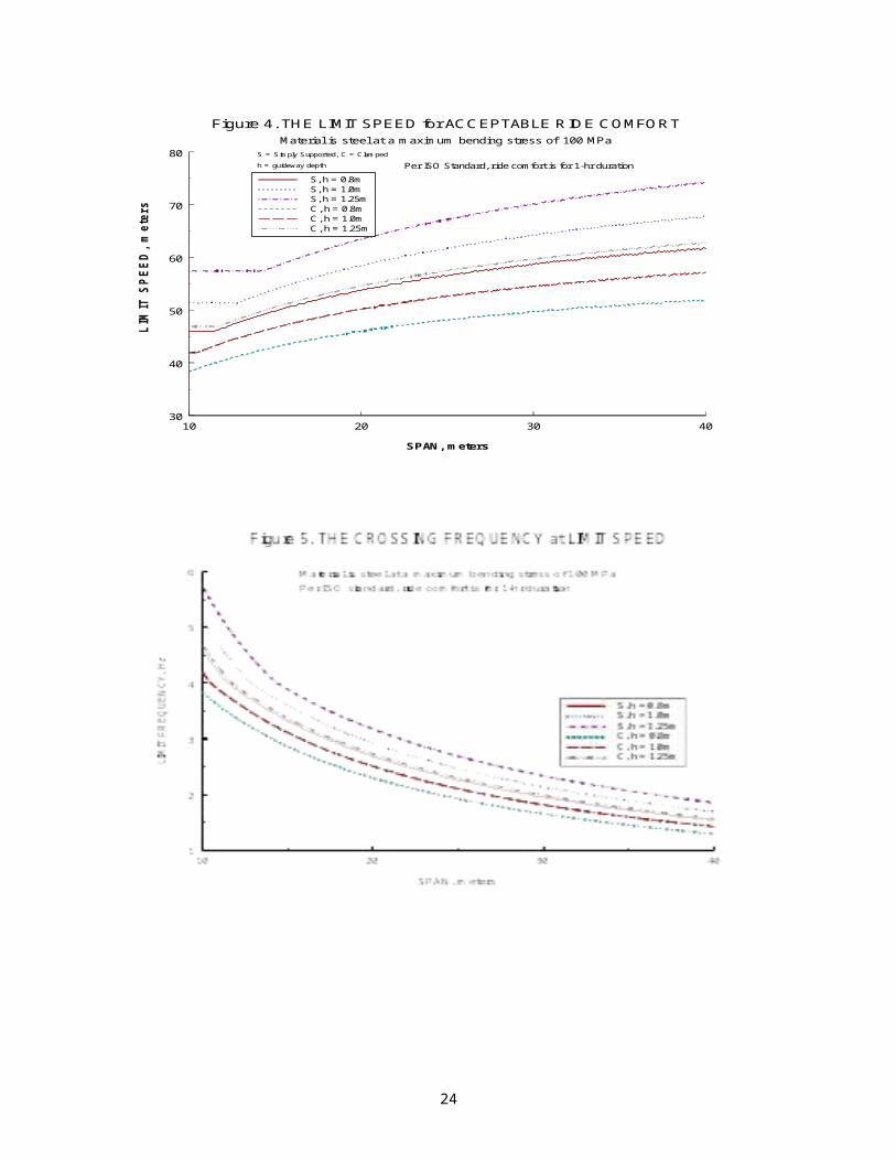
clamped span. From equation (16) we see that for fixed and fixed h, so the limit span for the clamped beam is longer than for the simply supported beam by a factor of 1 .51/2 = 1 .225 or by 22.5%. This is an important fact to keep in mind when examining the limit speeds shown in Figures 4 and 6. We see that the limit speed increases with span and, for a given span, is higher for the simply-supported beam. We have already noted that, if the comfort acceleration were the same in the two cases, the limit speed is higher for the simply-supported beam by a factor of 1.51/2. Note from Figure 4, which is for a 1-hr duration of acceleration, that for the case of h = 1 m and L = 27 m the limit speed for the simply-supported beam is about 62 m/s and for the clamped beam 53 m/s for a ratio of 1.17. (From Figure 6, for 2.5-hr duration of acceleration, the limit speed for the clamped beam drops to 42 m/s.) As shown in Figure 3, the price of this 17% increase in the limit speed in a simply-supported guideway is a guideway weight 65% greater. In any case, a limit speed of 53 m/s (191 km/hr or 118 mph) is well in excess of that needed for many practical applications. In Figures 5 and 7, the crossing frequencies corresponding to the limit speeds are shown. We see that in almost all cases the limit frequency is in the range of 1 to 4 Hz where the comfort acceleration drops rapidly as frequency in-creases. It is necessary to take these frequencies into account in design of the vehicle suspension system.
Because of interest in maglev systems operating on elevated guideways at speeds up to 300 mph (480 km/hr, or 134 m/s) it is useful to examine the conditions under which such speeds would be comfortable for the passenger. Thus, the results of Figures 8 and 9 were calculated. Only simply-supported spans were calculated because they permit higher speeds than clamped spans. Note that with spans up to 80 m, 134 m/s cannot be reached without a beam depth of over 5 meters if the fully-loaded design stress is 100 MPa. Note from the right-hand form of equations (23) that, for a given peak acceleration, the limit speed varies as
Thus, higher limit speeds require, for a given beam, smaller maximum loadings to reduce the maxi-
13
mum bending stress, but from equation (16) the price is greater guideway weight. Figure 9 shows that for the long-span beams required for very high speeds, the beam weight becomes excessive unless the depth is in the range of 3 to 4 meters.
Conclusions
PRT guideways have been analyzed in this paper based on a result of dynamic analysis of vehicles moving across flexible spans by SWR, in which it was found that the shorter the headway between vehicles the smaller is the difference between dynamic and static deflections, and that in the limit of zero nose-to-tail spacing between vehicles the static and dynamic deflections are the same. This result occurs because in the limit case the load is practically uniform and non-time varying. The analysis is applicable to systems in which small vehicles operated at a full-range of speeds including speeds applicable to inter-city travel. The following results were found:
The load-supporting weight of the guideway is directly proportional to additional loads applied, called the payload.
If a guideway is stressed to its design limit, the ratio of guideway weight to payload is more than 50% higher with simply-supported spans than if the guideway is clamped to the support posts.
The guideway width needed to resist wind or earthquake loads is less than the required depth.
The limit speed for acceptable ride comfort increases with span because longer spans mean lower crossing frequencies, and lower frequencies usually imply higher tolerable amplitudes of vertical accel-eration.
For given design stress, beam depth and span, the limit speed is higher for simply-supported guide-ways than for clamped guideways, but at a heavy price in guideway weight.
To minimize guideway cost, in some cases the vehicles must cruise at a crossing frequency higher than the fundamental natural frequency of the fully loaded guideway, but generally lower than the fundamental natural frequency of the empty guideway. This practice will be satisfactory if vehicles operating at less than maximum throughput are spaced randomly, as is the case if the control sys-tem is asynchronous. By use of active control, crossing frequencies that may be a problem can be avoided. This practice is new for guideway transit, but has been common for decades in the opera-tion of large turbines, where the phenomenon is the same, and substantial cost savings result. Cor-responding large savings in guideway cost can be expected.
Final proof of the design must come from dynamic analysis of moving vehicles across flexible spans on straight and curved guideways.
References
14
Anderson, J. E., 1978. Transit Systems Theory, Chapter 10 "Guideway Structures," Lexington Books, D. C. Heath.
Anderson, J. E., 1997. "Control of Personal Rapid Transit Systems," Journal of Advanced Transportation, 32:1(1998).
Anderson, J. E., 1990. “Ride Comfort.”
Irving, Jack H., Bernstein, Harry, Olson, C. L., and Buyan, Jon, 1978. Fundamentals of Personal Rapid Transit, Lexington Books, D. C. Heath and Company, pp 219-220.
Scruton, C. and Rogers, E. W. E., 1971. "Steady and Unsteady Wind Loading." Phil. Trans. Royal Society of Lon-don, A. 269, pp. 353-379.
Snyder, J. E., Wormley, D. N., and Richardson, H. H., 1975. "Automated Guideway Transit Systems Vehicle-Ele-vated Guideway Dynamics: Multiple-Vehicle Single Span Systems," Report No. UMTA MA-11-0023-75-1, De-partment of Transportation, Washington, D. C.
15
10 20 30 40
SPAN, meters
0.00
0.02
0.04
0.06
0.08
0.10
0.12
0.14
0.16
0.18
0.20
DEF
LEC
TIO
N, m
eter
sFigure 1. DEFLECTION of SIMPLY-SUPPORTED and CLAMPED GUIDEWAYS
Material is steel at a maximum bending stress of 100 MPa
S, h = 0.8mS, h = 1.0mS, h = 1.25mC, h = 0.8mC, h = 1.0mc, h = 1.25m
S = Simply Supported, C = Clampedh = guideway depth
10 20 30 40
SPAN, meters
0
2
4
6
8
10
12
LOA
DED
NA
TUR
AL
FREQ
UEN
CY,
Hz
Figure 2. NATURAL FREQUENCY of SIMPLY-SUPPORTED and CLAMPED GUIDEWAYSMaterial is steel at a maximum bending stress of 100 MPa
S, h = 0.8mS, h = 1.0mS, h = 1.25mC, h = 0.8mC, h = 1.0mC, h = 1.25m
S = Simply Supported, C = Clamped
h = guideway depth
16
10 20 30 40
SPAN, meters
0.0
0.2
0.4
0.6
0.8
1.0
1.2
1.4
1.6
1.8
RA
TIO
of B
EAM
WEI
GH
T TO
PA
YLO
AD
Figure 3. THE RATIO OF BEAM WEIGHT TO PAYLOAD in GUIDEWAYSMaterial is steel at a maximum bending stress of 100 Mpa
S, h = 0.8mS, h = 1.0mS, h = 1.25mC, h = 0.8mC, h = 1.0mC, h = 1.25m
S = Simply Supported, C = Clamped
h = guideway depth
17
10 20 30 40
SPAN, meters
30
40
50
60
70
80LI
MIT
SPE
ED, m
eter
sFigure 4. THE LIMIT SPEED for ACCEPTABLE RIDE COMFORT
Material is steel at a maximum bending stress of 100 MPa
S, h = 0.8mS, h = 1.0mS, h = 1.25mC, h = 0.8mC, h = 1.0mC, h = 1.25m
S = Simply Supported, C = Clamped
h = guideway depth Per ISO Standard, ride comfort is for 1-hr duration
18
10 20 30 40
SPAN, meters
30
40
50
60
70
80LI
MIT
SP
EE
D,
m/s
ec
S = Simply Supported, C = Clamped
h = guideway depth
Figure 6. THE LIMIT SPEED for ACCEPTABLE RIDE COMFORT
Material is steel at a maximum bending stress of 100 MPaPer ISO Standard, ride comf ort is f or 2.5-hr duration
S, h = 0.8mS, h = 1.0mS, h = 1.25mC, h = 0.8mC, h = 1.0mC, h = 1.25m
19
20
'Revised 5/18/2005'This program GDWYPROP.BAS calculates data for Figures 1-9 of the paper'"The Design of PRT Guideways."'Units are MKS
DEFDBL A-ZDIM I, J AS INTEGERDECLARE FUNCTION Apeak (f, J)
DIM h(6) AS CURRENCY 'beam depthDIM L AS CURRENCY 'spanDIM DeflS(3) AS DOUBLE 'deflection of simply-supported beamDIM FreqS(3) AS DOUBLE 'natural frequency of simply-supported beamDIM BemWS(6) AS DOUBLE 'ratio beam weight/payload weight for ss beamDIM Mu(6) AS DOUBLE 'quantity given by equation 16DIM DeflC(3) AS DOUBLE 'deflection of clamped beamDIM FreqC(3) AS DOUBLE 'natural frequency of clamped beamDIM BemWC(3) AS DOUBLE 'ratio beam weight/payload weight for clamped beamDIM LfqSa(3) AS DOUBLE 'limit frequency for ss beam at 1 hr durationDIM LfqSb(3) AS DOUBLE 'limit frequency for ss beam at 2.5 hr durationDIM LSpSa(3) AS DOUBLE 'limit speed for ss beam at 1 hr durationDIM LSpSb(6) AS DOUBLE 'limit speed for ss beam at 2.5 hr durationDIM LfqCa(3) AS DOUBLE 'limit frequency for clamped beam at 1 hr durationDIM LfqCb(3) AS DOUBLE 'limit frequency for clamped beam at 2.5 hr durationDIM LSpCa(3) AS DOUBLE 'limit speed for clamped beam at 1 hr durationDIM LSpCb(3) AS DOUBLE 'limit speed for clamped beam at 2.5 hr duration
DIM SHARED ComfAccl(4) AS DOUBLE
Pi = 4 * ATN(1)g = 9.80665 'acceleration of gravity, m/s^2E = 207 * (10) ^ 9 'modulus of elasticity, N/m^2ds = 76500 'density of steel, N/m^3S = 10 ^ 8 'design stress, N/m^2SE = S / ESD = S / dsk = .6 'beam shape factorh(1) = .8 'beam depth, mh(2) = 1 ' "h(3) = 1.25 ' "h(4) = 2.5 ' " for high-speed systemsh(5) = 3.5 ' " "h(6) = 4.5 ' " "
CONST f1 = 1 'break frequency in ride-comfort curveCONST f2 = 4 ' "CONST f3 = 8 ' "CONST f4 = 16 ' "ComfAccl(1) = .353 '1 hr comfort peak acceleration at f1, g'sComfAccl(2) = .173 '1 hr comfort peak acceleration at f2, g'sComfAccl(3) = .209 '2.5 hr comfort peak acceleration at f1, g'sComfAccl(4) = .102 '2.5 hr comfort peak acceleration at f2, g's
OPEN "DEFL.ASC" FOR OUTPUT AS #1OPEN "FREQ.ASC" FOR OUTPUT AS #2
21
OPEN "BEAM.ASC" FOR OUTPUT AS #3OPEN "LIMF1.ASC" FOR OUTPUT AS #4OPEN "LIMF25.ASC" FOR OUTPUT AS #5OPEN "LIMS1.ASC" FOR OUTPUT AS #6OPEN "LIMS25.ASC" FOR OUTPUT AS #7
CLS
FOR L = 10 TO 40 STEP .1 Term = (4 / 3) * SE * L ^ 2 / g 'term in Equation 23 'simple support FOR I = 1 TO 3 DeflS(I) = 5 * SE * L ^ 2 / 24 / h(I) FreqS(I) = (Pi / 8 / L) * SQR(g * h(I) / SE) Mu(I) = 2 * k * h(I) * SD / L ^ 2 BemWS(I) = 1 / (2 * Mu(I) - 1)
'calculate limit freq & speed for 1 hr duration f = .2 DO f = f + .01 IF Term * f ^ 2 / h(I) > Apeak(f, 1) THEN EXIT DO LOOP LfqSa(I) = f 'limit frequency LSpSa(I) = f * L 'limit speed
'calculate limit freq & speed for 2.5 hr duration f = .2 DO f = f + .01 IF Term * f ^ 2 / h(I) > Apeak(f, 3) THEN EXIT DO LOOP LfqSb(I) = f 'limit frequency LSpSb(I) = f * L 'limit speed NEXT I
'clamped support FOR I = 1 TO 3 DeflC(I) = .3 * DeflS(I) FreqC(I) = 1.851 * FreqS(I) BemWC(I) = 1 / (3 * Mu(I) - 1)
'calculate limit freq & speed for 1 hr duration f = .2 DO f = f + .01 IF 1.5 * Term * f ^ 2 / h(I) > Apeak(f, 1) THEN EXIT DO LOOP LfqCa(I) = f 'limit frequency LSpCa(I) = f * L 'limit speed
'calculate limit freq & speed for 2.5 hr duration f = .2 DO f = f + .01 IF 1.5 * Term * f ^ 2 / h(I) > Apeak(f, 3) THEN EXIT DO LOOP
22
LfqCb(I) = f 'limit frequency LSpCb(I) = f * L 'limit speed NEXT I WRITE #1, L, DeflS(1), DeflS(2), DeflS(3), DeflC(1), DeflC(2), DeflC(3) 'Fig 1 WRITE #2, L, FreqS(1), FreqS(2), FreqS(3), FreqC(1), FreqC(2), FreqC(3) 'Fig 2 WRITE #3, L, BemWS(1), BemWS(2), BemWS(3), BemWC(1), BemWC(2), BemWC(3) 'Fig 3 WRITE #4, L, LfqSa(1), LfqSa(2), LfqSa(3), LfqCa(1), LfqCa(2), LfqCa(3) 'Fig 5 WRITE #5, L, LfqSb(1), LfqSb(2), LfqSb(3), LfqCb(1), LfqCb(2), LfqCb(3) 'Fig 7 WRITE #6, L, LSpSa(1), LSpSa(2), LSpSa(3), LSpCa(1), LSpCa(2), LSpCa(3) 'Fig 4 WRITE #7, L, LSpSb(1), LSpSb(2), LSpSb(3), LSpCb(1), LSpCb(2), LSpCb(3) 'Fig 6NEXT LCLOSE #1CLOSE #2CLOSE #3CLOSE #4CLOSE #5CLOSE #6CLOSE #7
OPEN "HSBEAM.ASC" FOR OUTPUT AS #1OPEN "HSLIMSP.ASC" FOR OUTPUT AS #2'calculate properties for high-speed, simply-supported guidewaysFOR L = 20 TO 80 STEP .2 Term = (4 / 3) * SE * L ^ 2 / g FOR I = 4 TO 6 'calculate beam weight ratio (Figure 9) Mu(I) = 2 * k * h(I) * SD / L ^ 2 BemWS(I) = 1 / (2 * Mu(I) - 1) 'assume simply-supported beam only
'calculate limit speed for 2.5 hr duration (Figure 8) f = .2 DO f = f + .01 IF Term * f ^ 2 / h(I) > Apeak(f, 3) THEN EXIT DO LOOP LSpSb(I) = f * L 'limit speed NEXT I WRITE #1, L, BemWS(4), BemWS(5), BemWS(6) 'Fig 9 WRITE #2, L, LSpSb(4), LSpSb(5), LSpSb(6) 'Fig 8NEXT LCLOSE #1CLOSE #2
23
FUNCTION Apeak (f, J) IF f < f1 THEN Apeak = ComfAccl(J) ELSEIF f < f2 THEN ex = (f - f1) / (f2 - f1) Apeak = ComfAccl(J) * (ComfAccl(J + 1) / ComfAccl(J)) ^ ex ELSEIF f < f3 THEN Apeak = ComfAccl(J + 1) ELSE ex = (f - f3) / (f4 - f3) Apeak = ComfAccl(J + 1) * (ComfAccl(J) / ComfAccl(J + 1)) ^ ex END IFEND FUNCTION
Revised 5/19/2005
24