the detector control system for the hmpid detector in...
TRANSCRIPT

THE DETECTOR CONTROL SYSTEM FOR THE HMPID DETECTOR IN THE ALICE EXPERIMENT AT LHC
G. De Cataldo1, A. Franco1, I. Sgura2, A.Tauro2
1INFN sez. Bari Italy, 2Politecnico di Bari ,Italy
ABSTRACT The fully operational Detector Control System (DCS) for the High Momentum Particle
Identification Detector (HMPID), developed in PVSS 2.12.1, is described. As a future development,
some details on the implementation of the new DCS version in PVSS II v3.0 are also presented.
INTRODUCTION ALICE (A Large Ion Collider Experiment) [1] is the only experiment at LHC specifically designed to
investigate equilibrium as well as non equilibrium physics of strongly interacting matter in the energy
density range g B 1-1000 GeV/fm3 [2]. The experimental layout features several particle identification
sub-systems, based on various techniques, to cover the momentum range from a few hundred MeV/c
up to several GeV/c.
The High Momentum Particle Identification Detector (HMPID) [3], one of the ALICE sub-detectors,
consists of an array of seven proximity focusing RICH (Ring Imaging Cherenkov Detector) modules
each with an active area of about 1.3 x 1.3 m2. It was designed to identify r-K in the range 1 < p < 3
GeV/c and K-ヾ in the range 1.5 < p < 5 GeV/c. Its total active area of 11 m2 represents the largest scale
application of Multi Wires Proportional Chambers (MWPC) with high Quantum Efficiency (QE) CsI
segmented photo-cathodes.
The layout of the seven HMPID modules is shown in Fig.1.
Figure 1. The array of the seven HMPID modules located on the ALICE space-frame.
To operate the HMPID the integration and synchronization of six ancillary sub-systems is required:
the high voltage (HV), the low voltage (LV), the gas, the cooling, the C6F14 circulation system (LCS)
and finally the physical parameter monitoring system.
The automatic detector operations, the single subsystem operations and the integration of the control
in the ALICE DCS are mandatory features that can be simultaneously provided if the detector
behaviour is modelled with finite state machines (FSM). In this DCS prototype this technique has been
extensively used.
10th ICALEPCS Int. Conf. on Accelerator & Large Expt. Physics Control Systems. Geneva, 10 - 14 Oct 2005, PO1.017-1 (2005)

THE IMPLEMENTATION OF THE HMPID DCS
PVSS, the Framework, SMI++ and the Custom-made components: the development toolkits
The implementation of the first prototype of the HMPID DCS has been done using a set of
development environments namely: PVSS 2.12.1 [4], the Framework in PVSS (FW) [5] and the State
Manager Interface (SMI++) [6]. However, only some detector-specific, custom-made components,
developed by the HMPID DCS group, have permitted to succeed in the implementation of an effective
DCS. Although this DCS prototype can control the seven HMPID modules, it has been tested on a
reduced set of hardware which is enough to power on two detector modules. A short description of
each component and of the controlled hardware is hereinafter provided.
PVSS is the Slow Control And Data Acquisition system (SCADA) adopted at CERN for the controls
of the four experiments at LHC.
The Framework (developed at CERN) is a toolkit in PVSS for the developers which hides the PVSS
complex structure and helps to reduce the development effort as much as possible. In fig. 2 is shown
the Editor/Navigator panel of the FW. On the left side there is the HMPID HV hierarchy developed
within the FW while on the right side it is shown the custom-made panel for the connection of the HV
hardware with the control program. It has been specifically developed by the HMPID DCS group and
integrated in the FW. In fact this panel (or the similar one for the LV) allows to decide which HV
channel is connected to a specific HV sector (or segment) and, if the case, to replace in the control
program any fault channel with a spare working one, even on a different board.
Figure 2: The Editor/Navigator FW panel is shown. On the left side the detector HV hierarchy,
organised in modules and implemented using the FW, is shown. Displayed on the right side of the
panel is a custom-made feature developed by the HMPID DCS group. It allows for configuring or
swapping any HV fault channel with a working one.
The SMI++ (developed at CERN) provides a toolkit in PVSS to model the detector behaviour with
finite state machines. An introduction to the SMI++ language and to the usage of the FSM in the
detector control system can be found in [6]. Here only some details on the Control Units (CU) and
Device Units (DU) are given. The DU is a FSM with a PVSS script program providing an interface
with the hardware; it behaves according to a state diagram but does not contain any control program
able to take complex decisions. Each state is calculated on the bases of the hardware state. The DU is
able to convert an incoming action into a command for the hardware.
The CU is a FSM, which can control one or many DUs. In this hierarchy the CU is the parent and
the connected DUs are the children. The CU contains a control program, derived from its state
diagram and able to take complex decisions. The parent CU can control other CUs as well.
10th ICALEPCS 2005; G. De Cataldo, A. Franco, I. Sgura, A.Tauro et al. : The Detector Control System fo... 2 of 6
In the following the custom-made components complementing the SMI++ and the Framework are
shortly described.
The first one is a new firmware for the CAEN CANbus controller A1676W (developed in a joint
project with the CAEN Company) which can control up to eight WIENER PL500F8 LV power
supplies. This enhanced firmware permits the single channel on/off, the single channel trip-off and the
channels grouping for the bipolar Front-End electronics (FEE). These features, mandatory to power on
the HMPID FEE, are unfortunately missing on the PL500F8 model delivered by the WIENER
Company which in turn is the standard component in the FW. Details are reported in [7].
The second component is the so called SYdriver. It has been designed to speedup the DCS response
at the HV and LV channel’s status changing. It replaces the standard connection via OPC between
PVSS and the hardware.
The third component integrating the SMI++ is a PVSS script providing the majority computation on
the tripped HV channels and the software interlock between the LV and the HV sub-system. These
features have been fundamental in the HMPID FSM error handling.
Finally the fourth component is the electronic logbook and the logging facilities. During the detector
test beam campaign (2001-2004) it became evident that the DCS needed to be equipped with a logging
facility where the sequence of the FSM's commands, issued by the operator, and the corresponding
states had to be registered. This facility revealed to be crucial especially during the FSM error
recovering. The logging facility is described in the presentation of the HMPID DCS operation panels.
The controlled hardware consists of one CAEN system crate SY1527, five HV boards A1821P (for a
total of 60 HV channels), four PL500F8 (for a total of 32 LV channels 5 V 25 A each), one A1676W
CANbus controller housed in the SY1527 together with the five HV boards, and finally one Siemens
Programmable Logic Controller with 32 analogue input channels for T and P monitoring. In order to
power on the entire detector 49 HV channels and 98 LV channels are requested. Therefore, the
available 32 LV channels enable only two HMPID modules to be powered.
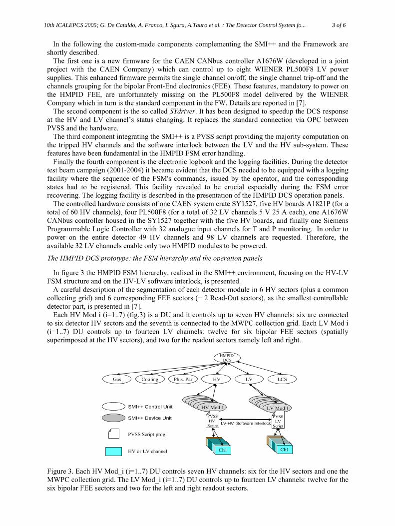
The HMPID DCS prototype: the FSM hierarchy and the operation panels
In figure 3 the HMPID FSM hierarchy, realised in the SMI++ environment, focusing on the HV-LV
FSM structure and on the HV-LV software interlock, is presented.
A careful description of the segmentation of each detector module in 6 HV sectors (plus a common
collecting grid) and 6 corresponding FEE sectors (+ 2 Read-Out sectors), as the smallest controllable
detector part, is presented in [7].
Each HV Mod i (i=1..7) (fig.3) is a DU and it controls up to seven HV channels: six are connected
to six detector HV sectors and the seventh is connected to the MWPC collection grid. Each LV Mod i
(i=1..7) DU controls up to fourteen LV channels: twelve for six bipolar FEE sectors (spatially
superimposed at the HV sectors), and two for the readout sectors namely left and right.
SMI++ Control Unit
SMI++ Device Unit
HMPID
DCS
PVSS Script prog.
HV LV
Mod 1Mod 1Mod 1Mod 1Mod 1HV Mod 1
Mod 1Mod 1Mod 1Mod 1Mod 1LV Mod 1
Phis. ParGas Cooling LCS
PVSS
HV
Script
PVSS
LV
Script
Ch1 Ch1HV or LV channel
LV-HV Software Interlock
Figure 3. Each HV Mod_i (i=1..7) DU controls seven HV channels: six for the HV sectors and one the
MWPC collection grid. The LV Mod_i (i=1..7) DU controls up to fourteen LV channels: twelve for the
six bipolar FEE sectors and two for the left and right readout sectors.
10th ICALEPCS 2005; G. De Cataldo, A. Franco, I. Sgura, A.Tauro et al. : The Detector Control System fo... 3 of 6

The HMPID Main control panel is reported in fig.4. It is the Graphic User Interface (GUI) of the
FSM process HMPID DCS (see fig.3). On the right side of the panel it is located the monitoring zone.
The seven modules with the logical state of the relevant part of the subsystems are shown. By double
clicking on any module the corresponding monitoring panel is opened (left bottom of fig.4). This GUI
layout has inspired the ALICE Control Coordination (ACC) standard reported in [8]. On the left side
of the main panel are located the FSM buttons of the six subsystems. From there, according to an
automatic and pre-defined sequence, the commands are executed by each subsystem. Any sub-system
can be excluded from the main hierarchy by opening the lock on the right side of the control button
and can be operated independently (partitioning).
Figure 4. The HMPID main operation panels and the Module monitoring panel (left bottom) are
shown.
In fig. 5 are reported the control panels of the Cooling (left) and LCS systems (right). They are not
conceived as for the final version however all the relevant parts for the controls and monitoring are
available. The HV and LV control panels will be presented later in the Error Handling section.
Figure 5. The main control panels of the cooling (right) and C6F14 liquid circulation (left) systems are
shown.
ALARM AND ERROR HANDLING As reported in [9] the intention of an alarm is to bring an anomalous situation to the attention of an
operator and as such alarms are considered to be messages, which are displayed to the operator via the
alarm display in PVSS and that are logged. An alarm does not initiate an action. Should an action be
required then this should be done within the FSM. According to the alarm severities the HMPID DCS
has been programmed to react differently. Thanks to the custom-made script interface between the
10th ICALEPCS 2005; G. De Cataldo, A. Franco, I. Sgura, A.Tauro et al. : The Detector Control System fo... 4 of 6

HV-LV channels and the relevant DU (see fig. 3), a threshold TH on the number N of the HV tripped
channels can be set. If N > TH (possible serious conditions on one entire detector module) then all the
HV channels on that module are switched off. If N ø TH then only the affected channels are switched
off. In both cases the new HV FSM state of the module becomes ERROR_REPAIR.
In order to protect the FEE from electrostatic discharge in the MWPC, a HV sector is not allowed to
be on if the corresponding FEE sector is off. In fig.6 (left and right panels) is shown the action of the
LV-HV software interlock. Since the FEE 1 sector is in over current then the corresponding HV sector
S1 (fig.6 right panel) is switched off via the software interlock.
Figure 6. The control panels of the LV and HV systems are shown. If a FEE sector is off for over
current, to prevent electrostatic discharge, the corresponding HV sector is switched off via the LV-HV
software interlock.
The recovering procedure from the ERROR_REPAIR in now manual and is based on the control
panels of the FEE and HV sectors (fig.7.). In the near future an automatic recovering feature will be
tested.
Figure 7. On the right part the control panel of the six FEE sectors and two readout sectors is shown.
On the left part the single FEE sector control is also shown. Similar panels for the HV are available.
In fig. 8 are shown the GUI for the logging and logbook facilities.
Figure 8. The logging and logbook facilities are shown. In the last row of the Logbook is reported
the operator’s comment entered via the Logging facility panel.
10th ICALEPCS 2005; G. De Cataldo, A. Franco, I. Sgura, A.Tauro et al. : The Detector Control System fo... 5 of 6
On the first line of the logbook is reported the trip event on the LV channel 11 corresponding to the
FEE 1 sector.
Two lines below it is described the software interlock action that has switched off the corresponding
HV S1 sector. Finally in the last line it is shown the comment entered by the operator with the cause
generating the trip.
INTEGRATION TEST IN THE ALICE ECS AND DCS FE COMPUTERS On March 2003 the first test of the ALICE Experiment Control System (ECS) was carried out using
the HMPID DCS which was the first prototype of the detector control in ALICE. The test was
comprehensive of the HMPID Trigger and DAQ control which allowed the remote data taking. This
test proved effective the ALICE ECS scheme now fully described in [10].
In April 2005 the HMPID DCS has been again exploited to verify the coping procedure of a generic
sub-detector control project on the ALICE DCS Front-End computer. Finally some preliminary tests
on the throughput capabilities of the ALICE DCS LAN have also been carried out.
FUTURE DEVELOPMENTS According to the prescriptions of the ALICE Controls Co-ordination (ACC) the final version of the
ALICE DCS will integrate only control projects developed within PVSS v.3.0 and the latest
Framework version. Therefore the implementation of a new and final HMPID DCS has already started
and it will be ready by the end of May 2006. In this new project each detector module will be
configured and operated independently from the others and the WIENER LV control will be replaced
by the CAEN EASY LV control. The state diagram of the FSM for the HV channel will include the
INTERMEDIATE state where lower HV setting values will protect the detector from over-current
during the LHC beam tuning. For the detector and sub-system state diagrams the prescription reported
in [11] will be followed.
SUMMARY AND CONCLUSION After five years of intense activities a complete prototype of the HMPID DCS has been developed.
This prototype has been realised using PVSS v. 2.12.1 as SCADA system, the Framework in PVSS as
toolkit for the control developers and the SMI++ to model the detector behaviour with finite state
machines. However, only custom-made components specifically designed by the HMPID group, have
permitted success in the DCS implementation. To comply with the ACC prescription, the development
of the new HMPID DCS is already underway in PVSS II 3.0. It will be ready by the end of May 2006
and it will contain the control of the CAEN LV EASY replacing the old WIENER PL500F8. Finally
the state diagram of the FSM HV channel will include the INTERMEDIATE state which will prevent
the over-current in the detector during the LHC beam tuning.
ACKNOWLEDGEMENTS The HMPID DCS group is grateful to L. Liberti, V. Rizzi from INFN Bari, Italy and J van Beelen
from CERN CH for their invaluable help in the hardware and cables setting.
REFERENCES [1] ALICE TDR, CERN/LHCC/95/71 LHCC/P3 15 December 1995
[2] ALICE Physic Performance Report: CERN/LHCC 2003-049 ALICE PPR Vol. 1, 7 Nov. 2003
[3] HMPID TDR: CERN/LHCC 98-19, ALICE TDR1, 14 August 1998
[4] http://itcobe.web.cern.ch/itcobe/Services/Pvss/GettingStarted/introductionToPvss.html
[5] http://itcobe.web.cern.ch/itcobe/Projects/Framework/welcome.html
[6] http://smi.web.cern.ch/smi/smi_1.html#chapter_1;
http://clara.home.cern.ch/clara/fw/FSMConfig.pdf
[7] https://edms.cern.ch/document/546975/1
[8] Guidelines and Conventions for ALICE PVSSII Control Software; ALICE-INT-05.Und. appr.
[9] http://itcobe.web.cern.ch/itcobe/Projects/Framework/Documentation/guidelinesDocument.pdf
[10] Trigger, DAQ, HLT and Control System: CERN-LHCC-2003-062, ALICE TDR 010, 7 Jan 2004
[11] http://alicedcs.web.cern.ch/AliceDCS/Documents/HV-LV_FSM_standard-v2.2.pdf
10th ICALEPCS 2005; G. De Cataldo, A. Franco, I. Sgura, A.Tauro et al. : The Detector Control System fo... 6 of 6