the determination of delamination strain energy release rate of
TRANSCRIPT
THE DETERMINATION OF DELAMINATION STRAIN ENERGYRELEASE RATE OF COMPOSITE BI-MATERIAL INTERFACE
Jaroslav Juracka∗ , Vladimir Matejak∗∗Brno University of Technology, Institute of Aerospace Engineering
[email protected]; [email protected]
Keywords: Composite, bi-material interface, energy release rate, delamination
Abstract
Increasing use of composite materials in aircraftstructures requires a development of new analy-sis methods. These methods should account forpossible influences of structural damage and im-perfections typically occurring in these materials.Delaminations are the main interest here.
Fracture mechanics and strain energy releaserate approach have been widely used for char-acterizing delamination in composite materials.This paper focuses on extending this approach todelaminations at bi-material interface of GRFPand CRFP. Combination of these materials is acommon design practice in small aircrafts andenables the utilization of carbon composite ma-terials superior mechanical properties and glasscomposite lower cost.
Modification of FRMM (Fixed Ratio MixedMode) testing method was used in order to getcritical strain energy release rate in various lev-els of mixed mode (mode I / mode II). Beamtheory analysis with conjunction of VCCT (Vir-tual Crack Closure Technique) was utilized forestablishing equations for previously mentionedtest method. Another modification of commontesting procedure was application of Aramis pho-togrammetry system during the measurement ofcrack tip propagation in a specimen and follow-ing image post-processing by Python program-ming language.
Only a narrow interval of mode mixity wasachieved by FRMM specimen configuration.More testing needs to be done in pure mode I and
Mode II condition in order to get a complete char-acterization of delamination behavior.
1 Introduction
Delamination is one of the most commonly ob-served failure modes in composite materials. Themost common sources of delamination are thematerial and structural discontinuities that giverise to interlaminar stresses. Delaminations usu-ally occur at stress-free edges, ply drops or re-gions subjected to out-of-plane loading, such asbending of curved beams. Delaminations maybe formed during manufacture under residualstresses or as a result of the lay-up process or in-service.
Fracture mechanics are commonly appliedfor analyzing delaminations, due to the crack-like type of discontinuity accompanying these de-fects. The strain energy release rate approach hasbeen used in most studies of composite delam-inations (both experimental and computational)instead of stress intensity approach which is typ-ically used for isotropic materials fracture me-chanics. The critical strain energy release rate,Gc, is a measure of fracture toughness and maybe different for three different types of loading(mode I - opening, mode II - in-plane shear, modeIII - out-of-plane shear). Usually delaminationsoccur in certain combination of this three modes.
Bi-material interface in composite laminatesmay be another source of delamination initia-tion, because the material and stress discontinu-ity at this interface. Very few studies were done
1
JAROSLAV JURACKA, VLADIMIR MATEJAK
so far, which includes the effect of delamina-tion between two dissimilar materials. In reallife constructions made of composite materials,for example small aircrafts, the combination ofglass and carbon reinforced plastics is a commondesign practice. This enables the utilization ofcarbon composite materials superior mechanicalproperties and glass composites lower cost.
Several methods have been developed fortesting of composites fracture toughness of a sin-gle material. A good overview of these methodsgive for example Ref. [2]. Fixed ratio mixedmode (FRMM) will be further analyzed in moredetail, accounting for the effect of bi-material in-terface. This test is simple to perform and vari-ous ratios between Mode I and Mode II can beachieved by modifying the geometry of speci-men.
2 Mixed mode delamination analysis
2.1 Beam theory
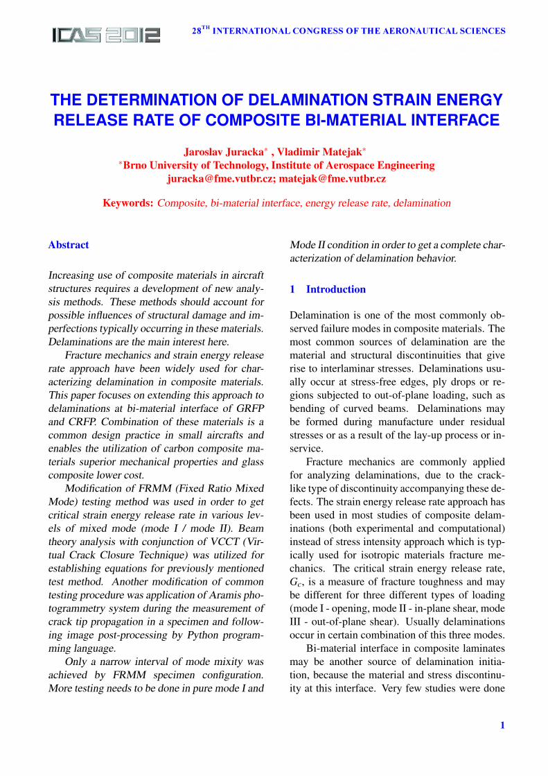
After the deduction of Williams [1], it is possi-ble to determine the energy release rate, G, of adelamination specimen based on the applied mo-ments and forces at the end of crack. Figure 1shows a composite laminate of thickness 2h andwidth b containing a delamination at an interfaceof the two components at a distance h1 from thetop surface.
Fig. 1 Interface crack
Let us first consider the end of a delamina-tion as shown in Figure 1 in which bending mo-ments M1 and M2 are applied to the upper andlower sections respectively. We may use theusual method of finding G and consider that crack
growths from section AB to CD by δa. G may bedefined as
G =1b
(dUe
da− dUs
da
)(1)
for the contour where Ue is the external workperformed and Us is the strain energy. This maybe rewritten as
G =1b
dUc
da=
1b
dUs
da(2)
where Uc is the complementary energy whichis equal to Us for the linear case. The strain en-ergy in a beam is given by
dUs
da=
12
M2
EI(3)
so the change within the contour is
∆Us =M2
12E1I1
∆a+M2
22E2I2
∆a−
− (M1 +M2)2
2EI∆a (4)
where
I0 =2bh3
3(5)
I1 =2bh3
112
= ξ3I0 (6)
I2 =2bh3
212
= (1−ξ)3I0 (7)
ξ =h1
2h(8)
(1−ξ) =h2
2h(9)
EI =bh3
2h1E2E1
12(h1E1 +h2E2)
[4+6
h1
h2+
+4(
h1
h2
)2
+E1
E2
(h1
h2
)3
+E2
E1
h2
h1
]
=2I0(1−ξ)3ξE2E1h(h1E1 +h2E2)
?
(10)
2
THE DETERMINATION OF DELAMINATION STRAIN ENERGY RELEASE RATE OF COMPOSITEBI-MATERIAL INTERFACE
?=
[4+6
ξ
1−ξ+4(
ξ
1−ξ
)2
+
+E1
E2
(ξ
1−ξ
)3
+E2
E1
1−ξ
ξ
] (11)
After substitution we may rewrite the strainenergy release rate from Eq.(11) as
G =3
4b2h3
(M2
1E1ξ3 +
M22
E2(1−ξ)3−
−(M1 +M2)2(h1E1 +h2E2)
2E2E1h(1−ξ)3ξ[?])
) (12)
2.1.1 Strain energy release rate for FRMM testspecimen
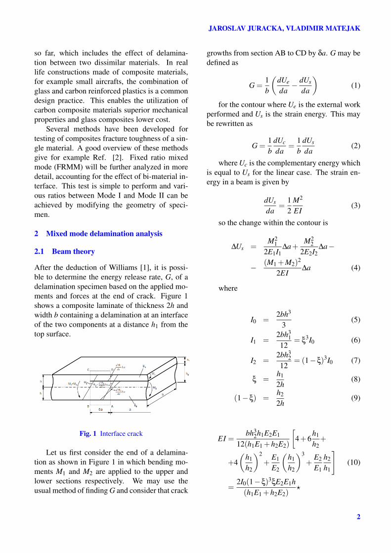
Fig. 2 Fixed ratio mixed mode test
Only one beam of the specimen is loaded bya load P in the FRMM test (Figure 2). If onlybending moments are taken into account and theload is applied to the upper beam, which thick-ness is h1, the resulting moments are M1 = −Paand M2 = 0. After simplification, the total strainenergy release rate is
G =3P2a2
4b2h3
(1
E1ξ3−
− h1E1 +h2E2
2E2E1h(1−ξ)3ξ[?]
) (13)
2.1.2 Mode partitioning
As the contribution of mode III is not consid-ered, the total energy release rate in equation (12)is the sum of mode I and mode II. To obtain the
contribution of each individual mode, equation(12) must be partitioned. This cannot be doneby simple analytical deduction, as will be showedlater in this chapter.
Pure mode II propagation occurs when thecurvature of both arms is the same and therefore
dθ1
da=
dθ2
da(14)
and if we have MII on the upper arm and ψMIIon the lower then
MII
E1I1=
ψMII
E2I2, i.e. ψ =
E2(1−ξ)3
E1ξ3 (15)
The opening mode only requires moments inopposite senses so we have M1 on the upper armand M1 on the lower arm so that the applied mo-ments may be resolved as
M1 = MII −MI
M2 = ψMII +MI(16)
i.e.
MI =M2 −ψM1
1+ψ
MII =M2 +M1
1+ψ
(17)
Substituting these expressions in Eq.(12), wehave
G =3
4b2h2
[M2
IE1ξ3 +
M2I
E2(1−ξ)3)+ (18a)
+M2
IIE1ξ3 +
M2II
E2(1−ξ)3)− (18b)
−M2II(1+ψ)2(h1E1 +h2E2)
2E1E2hξ(1−ξ)3[?]+ (18c)
+2ψMIMII
E2(1−ξ)3 −2MIMII
E1ξ3
](18d)
where on the line (18a) are pure mode Iterms, on the lines (18b) and (18c) pure modeII terms and on the line(18d) are cross-terms ofboth modes, which cannot be partitioned, unlessE1 = E2 and the contribution of the (18d) is 0.
3
JAROSLAV JURACKA, VLADIMIR MATEJAK
FE methods offer other possibility of investi-gating mode mixity ratio. This will described inthe next section.
2.2 VCCT
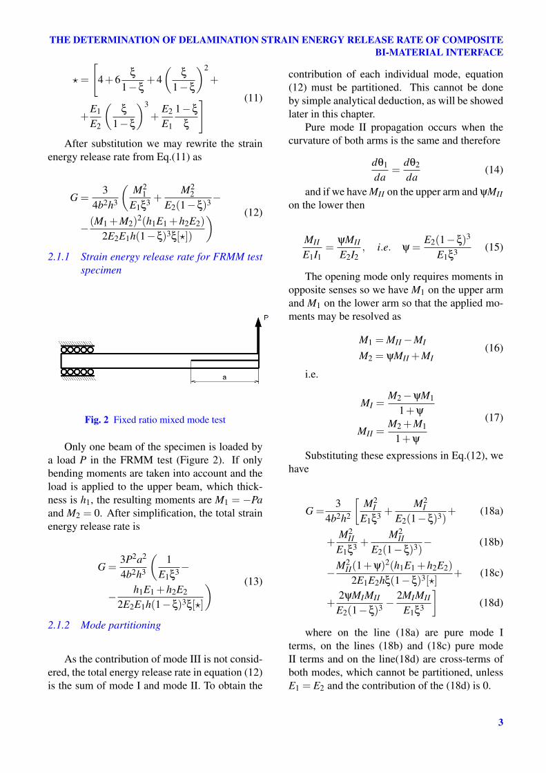
The goal of the FE analysis was to determinea mode mixity ratios of the bimaterial interfacein FRMM configuration. This ratio is a func-tion of two parameters: E1/E2 and thickness ratioξ. Twelve models were created using MSC.Marcsoftware, with different combinations of men-tioned parameters. Mode mixity function is thenobtained by surface interpolation of these points.
Fig. 3 FE model
Fig. 4 Initial crack definition
Figure 3 shows geometry and boundary con-ditions for one of the models. Three ratios ofE1/E2 were modelled: 0.1, 1 and 2. Glued con-tact was prescribed between lower and upper armof the specimen, where the initial crack was mod-elled as a glue deactivation region (Figure 4).Thickness ratio ξ = h1
h1+h2was set to 0.21, 0.515,
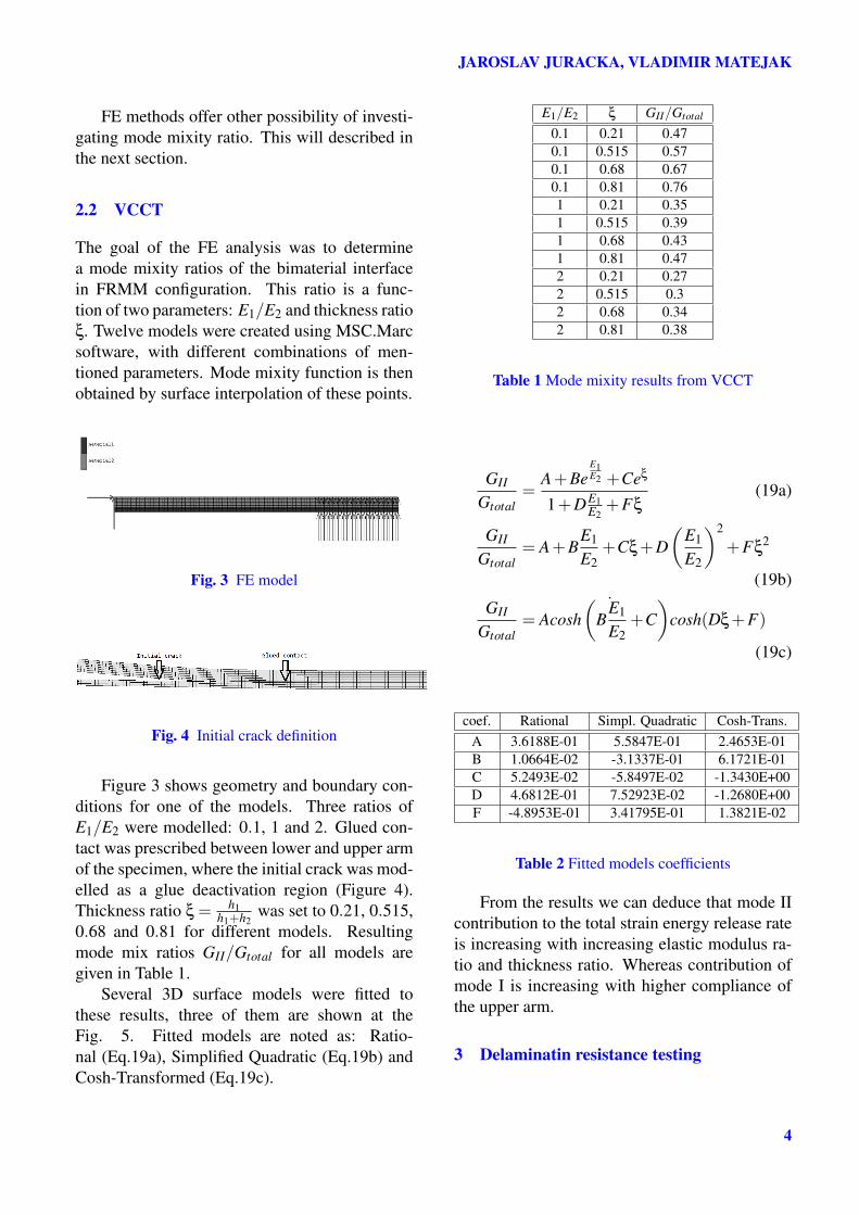
0.68 and 0.81 for different models. Resultingmode mix ratios GII/Gtotal for all models aregiven in Table 1.
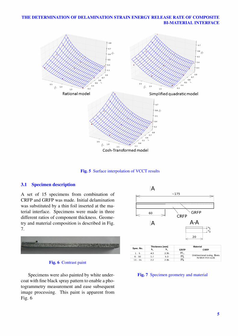
Several 3D surface models were fitted tothese results, three of them are shown at theFig. 5. Fitted models are noted as: Ratio-nal (Eq.19a), Simplified Quadratic (Eq.19b) andCosh-Transformed (Eq.19c).
E1/E2 ξ GII/Gtotal
0.1 0.21 0.470.1 0.515 0.570.1 0.68 0.670.1 0.81 0.761 0.21 0.351 0.515 0.391 0.68 0.431 0.81 0.472 0.21 0.272 0.515 0.32 0.68 0.342 0.81 0.38
Table 1 Mode mixity results from VCCT
GII
Gtotal=
A+BeE1E2 +Ceξ
1+DE1E2
+Fξ(19a)
GII
Gtotal= A+B
E1
E2+Cξ+D
(E1
E2
)2
+Fξ2
(19b)
GII
Gtotal= A
˙cosh
(B
E1
E2+C)
cosh(Dξ+F)
(19c)
coef. Rational Simpl. Quadratic Cosh-Trans.A 3.6188E-01 5.5847E-01 2.4653E-01B 1.0664E-02 -3.1337E-01 6.1721E-01C 5.2493E-02 -5.8497E-02 -1.3430E+00D 4.6812E-01 7.52923E-02 -1.2680E+00F -4.8953E-01 3.41795E-01 1.3821E-02
Table 2 Fitted models coefficients
From the results we can deduce that mode IIcontribution to the total strain energy release rateis increasing with increasing elastic modulus ra-tio and thickness ratio. Whereas contribution ofmode I is increasing with higher compliance ofthe upper arm.
3 Delaminatin resistance testing
4
THE DETERMINATION OF DELAMINATION STRAIN ENERGY RELEASE RATE OF COMPOSITEBI-MATERIAL INTERFACE
Fig. 5 Surface interpolation of VCCT results
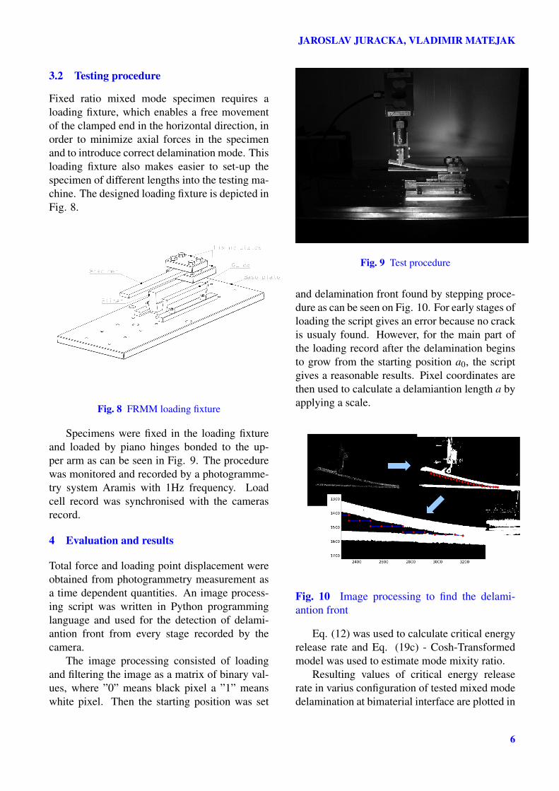
3.1 Specimen description
A set of 15 specimens from combination ofCRFP and GRFP was made. Initial delaminationwas substituted by a thin foil inserted at the ma-terial interface. Specimens were made in threedifferent ratios of component thickness. Geome-try and material composition is described in Fig.7.
Fig. 6 Contrast paint
Specimens were also painted by white under-coat with fine black spray pattern to enable a pho-togrammetry measurement and ease subsequentimage processing. This paint is apparent fromFig. 6
Fig. 7 Specimen geometry and material
5
JAROSLAV JURACKA, VLADIMIR MATEJAK
3.2 Testing procedure
Fixed ratio mixed mode specimen requires aloading fixture, which enables a free movementof the clamped end in the horizontal direction, inorder to minimize axial forces in the specimenand to introduce correct delamination mode. Thisloading fixture also makes easier to set-up thespecimen of different lengths into the testing ma-chine. The designed loading fixture is depicted inFig. 8.
Fig. 8 FRMM loading fixture
Specimens were fixed in the loading fixtureand loaded by piano hinges bonded to the up-per arm as can be seen in Fig. 9. The procedurewas monitored and recorded by a photogramme-try system Aramis with 1Hz frequency. Loadcell record was synchronised with the camerasrecord.
4 Evaluation and results
Total force and loading point displacement wereobtained from photogrammetry measurement asa time dependent quantities. An image process-ing script was written in Python programminglanguage and used for the detection of delami-antion front from every stage recorded by thecamera.
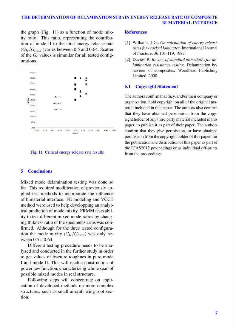
The image processing consisted of loadingand filtering the image as a matrix of binary val-ues, where ”0” means black pixel a ”1” meanswhite pixel. Then the starting position was set
Fig. 9 Test procedure
and delamination front found by stepping proce-dure as can be seen on Fig. 10. For early stages ofloading the script gives an error because no crackis usualy found. However, for the main part ofthe loading record after the delamination beginsto grow from the starting position a0, the scriptgives a reasonable results. Pixel coordinates arethen used to calculate a delamiantion length a byapplying a scale.
Fig. 10 Image processing to find the delami-antion front
Eq. (12) was used to calculate critical energyrelease rate and Eq. (19c) - Cosh-Transformedmodel was used to estimate mode mixity ratio.
Resulting values of critical energy releaserate in varius configuration of tested mixed modedelamination at bimaterial interface are plotted in
6
THE DETERMINATION OF DELAMINATION STRAIN ENERGY RELEASE RATE OF COMPOSITEBI-MATERIAL INTERFACE
the graph (Fig. 11) as a function of mode mix-ity ratio. This ratio, representing the contribu-tion of mode II to the total energy release rate(GII/Gtotal )varies between 0.5 and 0.64. Scatterof the Gc values is simmilar for all tested config-urations.
Fig. 11 Critical energy release rate results
5 Conclusions
Mixed mode delamination testing was done sofar. This required modification of previously ap-plied test methods to incorporate the influenceof bimaterial interface. FE modeling and VCCTmethod were used to help developping an analyt-ical prediction of mode mixity. FRMM tests abil-ity to test different mixed mode ratios by chang-ing thikness ratio of the specimens arms was con-firmed. Although for the three tested configura-tion the mode mixity (GII/Gtotal) was only be-tween 0.5 a 0.64.
Different testing procedure needs to be ana-lyzed and conducted in the further study in orderto get values of fracture toughnes in pure modeI and mode II. This will enable construction ofpower law function, characterizing whole span ofpossible mixed modes in real structure.
Following steps will concentrate on appli-cation of developed methods on more complexstructures, such as small aircraft wing root sec-tion.
References
[1] Williams, J.G., On calculation of energy releaserates for cracked laminates. International Journalof Fracture, 36:101-119, 1987.
[2] Davies, P., Review of standard procedures for de-lamination resistance testing. Delamination be-haviour of composites, Woodhead PublishingLimited, 2008.
5.1 Copyright Statement
The authors confirm that they, and/or their company ororganization, hold copyright on all of the original ma-terial included in this paper. The authors also confirmthat they have obtained permission, from the copy-right holder of any third party material included in thispaper, to publish it as part of their paper. The authorsconfirm that they give permission, or have obtainedpermission from the copyright holder of this paper, forthe publication and distribution of this paper as part ofthe ICAS2012 proceedings or as individual off-printsfrom the proceedings.
7