the development of a small scale gas turbine to assist in...
TRANSCRIPT

University of Southern Queensland - Toowoomba Campus
FACULTY OF ENGINEERING
The Development of a Small Scale Gas Turbine
to assist in the analysis of Coal Seam Gas as an
Alternative Stationary Jet Fuel for Australia
Supervisor: Talal Yusaf
Submitted by: Rhys Kirkland
0050079784
In fulfilment of the requirements of
Courses ENG 4111 and 4112 Research Project
Towards the degree of
Bachelor of Engineering – Mechanical Engineering
Submitted October 28th 2010
The report presented is the sole work of the author. None of this report is plagiarised (in whole or part) from a
fellow student's work, or from any un-referenced outside source.

ENG4111/4112 Research Project
Page 2 of 121
Abstract
This project aims to investigate Coal Seam Gas (CSG) as an alternative fuel for stationary
gas turbine engines. CSG is a new and emerging technology especially in Queensland
which has extensive and very attainable reserves. Technological and infrastructural
developments are making CSG more attainable and more cost effective as an alternative
fuel for domestic use, as a replacement for petrol and diesel fuels, heating and cooling,
and also for export.
There are two essential facets of this project being a detailed analysis of the
transportation and distribution issues, and the development of a small scale gas turbine
engine.
The model turbine has been built as a basis for experiment to compare fuel consumption,
and thermal efficiency of CSG compared to another appropriate fossil fuel.
Transportation and distribution will be analysed through research into CSG extraction and
refinement, existing CSG infrastructure, expected points of use in the context of stationary
jet engines, and the required infrastructure to provide the gas to the expected points of
use.
Based on the research and preliminary testing conducted in this report it was concluded
that CSG is a very feasible fuel which will only become cheaper with time due to significant
investments in infrastructure and technology relating to CSG. The running cost
calculations based on the model engine’s collected test data provided a running cost
saving of 58.1% for CNG over LPG. This is a significant margin which does not consider
case by case variables such as specific infrastructure installation costs however does allow
for significant initial investment due to the significant saving in running costs.

ENG4111/4112 Research Project
Page 3 of 121
Table of Contents
Abstract ................................................................................................................................. 2
List of Figures................................................................................................. ........................ 7
List of Tables.......................................................................................................................... 8
List of Appendices.................................................................................................................. 9
Glossary of Technical Terms.................................................................................................. 9
Chapter 1
INTRODUCTION
1.1 Introduction................................................................................................................... 13
1.2 Aims and Objectives ...................................................................................................... 15
1.3 Methodology ................................................................................................................. 16
1.4 Resource Requirements................................................................................................. 17
Chapter 2
Project Background
2.1 Introduction................................................................................................................... 18
2.2 Natural Gas Introduction, Composition, Sources and Availability................................. 18
2.3 Natural Gas Extraction, Refining, Transportation and Storage..................................... 19
2.4 Natural Gas as a Fuel for Combustion Engines............................................................. 21
2.5 Coal Seam Gas............................................................................................................... 21
2.6 Safety Issues When Working With Natural Gas............................................................ 22

ENG4111/4112 Research Project
Page 4 of 121
2.7 Emissions of Natural Gas Engines................................................................................. 22
2.8 Stationary Gas Turbine Applications Within Australia.................................................. 23
2.9 Manufacturers of Stationary Gas Turbines................................................................... 24
2.10 Comparison of Gas Turbine Engines to Compression Ignition engines....................... 25
2.11 Summary...................................................................................................................... 25
Chapter 3
COAL SEAM GAS ANALYSIS
3.1 Introduction...................................................................................... ............................. 28
3.2 Industry Overview.......................................................................................................... 28
3.2.1 Existing Distribution Infrastructure............................................................................. 32
3.3 Natural Gas Costs Analysis ............................................................................................ 33
3.4 Conclusion...................................................................................................................... 36
Chapter 4
CONSEQUENTIAL EFFECTS
4.1 Sustainability................................................................................................................. 38
4.2 Ethical Responsibility.................................................................................................... 41
4.3 Natural Gas as a Fuel..................................................................................................... 42
4.4 Safety Issues.................................................................................................................. 42

ENG4111/4112 Research Project
Page 5 of 121
Chapter 5
GAS TURBINE HISTORY AND PRINCIPLES OF OPERATION
5.1 Introduction ................................................................................................................. 43
5.2 Gas Turbine Origins....................................................................................................... 43
5.3 Basic Turbine Cycles...................................................................................................... 43
5.4 Principles of Operation................................................................................................. 44
5.5 Conclusion..................................................................................................................... 46
Chapter 6
MODEL DESIGN & CONSTRUCTION
Objectives ........................................................................................................................... 47
6.1 Introduction .................................................................................................................. 47
6.2 Design Requirements & Constraints ............................................................................. 48
6.3 System Processes .......................................................................................................... 50
6.4 Conceptual Design Analysis............................................................................................ 51
6.4.1 Turbocharger Considerations ..................................................................................... 51
6.4.2 Combustion Chamber Design...................................................................................... 52
6.4.3 Combustion Chamber Sizing....................................................................................... 53
6.4.4 Combustion Chamber Pipe Work Layout.................................................................... 54
6.4.5 Combustion Liner Design............................................................................................ 55
6.4.6 Afterburner Design..................................................................................................... 56
6.5 Materials Selection........................................................................................................ 57
6.6 3-D Prototype Creation and Analysis............................................................................. 58

ENG4111/4112 Research Project
Page 6 of 121
6.7 Cutting List .................................................................................................................... 61
6.8 2-D Prototype Engineering Construction Drawings....................................................... 63
6.9 Construction................................................................................................................... 63
6.10 Conclusion ................................................................................................................... 72
Chapter 7
SMALL ENGINE PERFORMANCE
7.1 Introduction................................................................................................................... 73
7.2 Aims and Objectives....................................................................................................... 73
7.3 Test Apparatus .............................................................................................................. 74
7.4 Test Procedure .............................................................................................................. 76
7.5 Results ........................................................................................................................... 78
7.6 Thermal Efficiency Calculation ...................................................................................... 79
7.7 Design Appraisal and Discussion of Turbine Failure....................................................... 85
7.8 Conclusion ..................................................................................................................... 89
Chapter 8
PROJECT CONCLUSION
8.1 Introduction .................................................................................................................. 92
8.2 Summary ....................................................................................................................... 92
8.3 Conclusion ..................................................................................................................... 99
8.4 Future Work ................................................................................................................ 101

ENG4111/4112 Research Project
Page 7 of 121
List of References .............................................................................................................. 102
Appendices ........................................................................................................................ 104
List of Figures
Figure 2.1: Insulated Liquefied Natural Gas tank on a truck................................................ 20
Figure 2.2: Natural gas turbine co-generation plant by Sinklair Knight Merz ..................... 24
Figure 2.3: Turbec manufactured gas turbine based co-generation plant .......................... 25
Figure 3.1: Major Coal basins in Queensland ..................................................................... 29
Figure 5.1: The Brayton cycle. ............................................................................................. 44
Figure 5.2: The simple cycle gas turbine layout. ................................................................. 44
Figure 5.3: A radial flow simple cycle gas turbine based on a turbocharger....................... 46
Figure 6.1: The completed 3-D model of the combustion chamber.................................... 58
Figure 6.2: Pressure distribution within the 3-D model....................................................... 59
Figure 6.3: Velocity distribution within the 3-D model........................................................ 60
Figure 6.4: Side view of the completed combustion chamber............................................ 65
Figure 6.5: Top view of the completed combustion chamber............................................. 66
Figure 6.6: Side view of the completed combustion liner................................................... 66
Figure 6.7: Top view of the completed combustion liner.................................................... 67
Figure 6.8: Side view of completed afterburner.................................................................. 68
Figure 6.9: Top view of the afterburner .............................................................................. 69
Figure 6.10: Belt driven oil pump apparatus........................................................................ 70

ENG4111/4112 Research Project
Page 8 of 121
Figure 6.11: Dash with installed control switches and gauges............................................ 70
Figure 6.12: Completed model apparatus ready for testing................................................ 72
Figure 7.1: Test apparatus. .................................................................................................. 75
Figure 7.2: Close up of turbocharger turbine wheel pre-failure.......................................... 87
Figure 7.3: Close up of turbocharger turbine wheel post-failure........................................ 87
List of Tables
Table 3.1: Australian natural gas consumption.................................................................... 29
Table 3.2: Fuel cost and volume analysis. ........................................................................... 35
Table 6.1: Initial costing of the combustion chamber construction.................................... 61
Table 6.2: Initial costing of the complete model construction............................................ 62
Table 6.3: Initial experimental apparatus cost..................................................................... 63

ENG4111/4112 Research Project
Page 9 of 121
List of Appendices
Appendix A – Risk Assessments ........................................................................................ 104
Appendix B – Oil System Specification............................................................................... 114
Appendix C – Turbocharger Specifications........................................................................ 118
Appendix D – Combustor Formula ................................................................................... 119
Appendix E – Combustion Chamber Construction Drawings............................................ 120
Glossary of Technical Terms
CSG – Coal Seam Gas – A naturally occurring Methane rich gas.
NG – Natural Gas – A Methane rich gas.
LPG – Liquefied Petroleum Gas – A commonly used petroleum based fuel gas.
CBM – Coal Bed Methane – Another name for Coal Seam Gas.
CNG – Compressed Natural Gas – Natural gas is compressed to increase the energy
density for storage and transport.
LNG – Liquefied Natural Gas – Natural gas is liquefied to increase the energy density
for storage and transport.
Co-generation – a term referring to the extraction of multiple energy sources from
one process (eg. Heat energy and shaft power from a gas turbine)
USQ – The University of Southern Queensland
Hydrocarbon – An organic compound consisting of hydrogen and carbon.
Biogas – A form of natural gas produced by the biological breakdown of organic
matter.
Conventional natural gas – Natural gas sourced from oil fields or natural gas fields.
Un-conventional natural gas – Natural gas sourced all other sources.

ENG4111/4112 Research Project
Page 10 of 121
Dewar – A heavily insulated and evacuated storage vessel for LNG.
Octane number – A measure of a fuels resistance to auto-ignition.
Thermal efficiency – A ratio of the work output to the supplied heat energy.
CH4 – Chemical formula for Methane.
NOx – Nitrogen Oxides produced during some combustion processes.
Stoichiometric – A measure of how well the fuel is burnt in the combustion process.
Lean burn operation – A process where the air/fuel ratio is decreased significantly
allowing savings in fuel consumption.
Ppm – Parts per million - A measurement of gas quantities.
Kinetic energy – The energy an object posses as a result of its motion.
Adiabatic – A thermodynamic process where no heat is transferred to the working
fluid.
AutoCAD – An engineering drawing suite.
2-D – Two Dimensional.
3-D – Three Dimensional.
CFD – Computational Fluid Dynamics.

ENG4111/4112 Research Project
Page 11 of 121
University of Southern Queensland
Faculty of Engineering and Surveying
Limitations of Use
The Council of the University of Southern Queensland, its Faculty of Engineering and Surveying,
and the staff of the University of Southern Queensland, do not accept any responsibility for the
truth, accuracy or completeness of material contained within or associated with this dissertation.
Persons using all or any part of this material do so at their own risk, and not at the risk of the
Council of the University of Southern Queensland, its Faculty of Engineering and Surveying or the
staff of the University of Southern Queensland.
This dissertation reports an educational exercise and has no purpose or validity beyond this
exercise. The sole purpose of the course pair entitled "Research Project" is to contribute to the overall education within the student’s chosen degree program. This document, the associated
hardware, software, drawings, and other material set out in the associated appendices should not be
used for any other purpose: if they are so used, it is
entirely at the risk of the user.
Prof Frank Bullen
Dean
Faculty of Engineering and Surveying
ENG4111 & ENG4112 Research Project

ENG4111/4112 Research Project
Page 12 of 121
Certification
I certify that the ideas, designs and experimental work, results, analyses and conclusions set
out in this dissertation are entirely my own effort, except where otherwise indicated and
acknowledged.
I further certify that the work is original and has not been previously submitted for
assessment in any other course or institution, except where specifically stated.
Rhys Jarod Kirkland
Student Number: 0050079784
___________________________________
Signature
___________________________________
Date

ENG4111/4112 Research Project
Page 13 of 121
Chapter 1 – Introduction
1.1 Introduction
Throughout the known history of mankind natural resources have existed in abundance
and been exploited in varying ways for our benefit. Today – in the 21st century –
essentially the same process is conducted on an ever increasing scale. Energy
consumption rates have increased exponentially with the world population growth as
more people in developing countries are expecting to live the western energy intensive
lifestyle.
A sobering fact is conventional non-renewable energy sources, as the name suggests, are
finite in reserves and will run out in the not too distant future. This has become more
obvious in recent times since the cost of exploration, extraction, production, and
distribution of crude oil based fuels is increasing to a point where society is pushing for a
viable alternative. Environmental pressure, political pressure, and increasing tax and levy
rates are also pushing this development in alternative fuels.
It is widely accepted that renewable energy sources are without doubt the long-term
solution for our energy needs. Development of these technologies is making
unprecedented progress, however this technology faces several issues. Some of these
include low natural energy density available for collection, inability to provide peak power
at times of high demand without an energy storage system, highly energy intensive
equipment construction, and associated high cost. These issues will certainly be addressed
in the upcoming years with technological developments powered by investment, and
renewable energy sources will prevail as the energy source of choice, however in the
interim period an alternative energy source needs to be implemented.

ENG4111/4112 Research Project
Page 14 of 121
Coal Seam Gas (CSG) (also known as Coal Bed Methane – CBM) is naturally occurring
methane rich gas mostly held within the coal molecular structure under pressure. This
pressure is essential for the gas to stay within the structure of the coal, so when the coal
seam is drilled and this pressure is released, then so too is the gas. An advantage of CSG is
it mostly contains much less heavier hydrocarbons such as propane or butane, and also
less carbon dioxide than fossil natural gas. CSG can be transported in compressed (CNG) or
liquid form (LNG) just as other natural gasses.
Although not a permanent solution, CSG is an excellent alternative to conventional fossil
fuels for the purpose of energy production and transport. In Queensland significant
reserves of CSG are located in the Surat and Bowen basin, and in an increasingly carbon
constrained economy these reserves will play a big role in energy generation in the near
future. An advantage about using CSG for these purposes is existing vehicles or power
plants can easily be converted to run on the new fuel. Natural gas fuelled power plants
can be constructed based on gas turbines using co-generation technology and achieve
significantly higher efficiencies than conventional coal fired power stations (around 80%
compared to 36%)[5]. When used in electricity generation, natural gas fired power plants
emit approximately 45% of the emissions of coal fired power stations(10).
This report is targeted at all gas turbines aside from those found in aircraft (or any
application where weight is an issue). These can be ships, large hovercraft, and especially
high efficiency power plants and co-generation applications. Currently gas turbines
operate on many different fuels mostly depending on their location and application. This
report will assess the feasibility of the fuel conversion and provide recommendations
toward the transition to CSG.

ENG4111/4112 Research Project
Page 15 of 121
1.2 Aims and Objectives
This project aims to investigate Coal Seam Gas (CSG) as an alternative fuel for stationary
gas turbine engines (in particular gas turbine based co-generation systems). In order to
satisfactorily complete this project there are two essential aspects which need to be
covered.
The first is a detailed analysis of the transportation and distribution issues. These
issues are a major part of this project because of the nature of Natural Gas (NG) and
its associated low energy density. Research into CSG extraction and refinement will
help create an understanding of what CSG is, and where it comes from. Existing CSG
infrastructure will also be researched which will help in making conclusions about CSG
as an alternative fuel by assessing the void between the existing infrastructure and
the required infrastructure. Research into stationary turbine applications in Australia
and expected points of use for the gas is also important when considering
infrastructure needs for CSG.
The second is the development of a small scale gas turbine. To give this project a
practical aspect this model engine will be developed and used to obtain experimental
results in order to deduct conclusions about CSG as a widespread alternative fuel for
stationary gas turbine engines. From this engine fuel consumption, combustion
chamber pressure, and exhaust temperature data will be collected. Ideally the engine
would be run on both CSG and LPG, however attaining any sort of methane rich gas to
get comparative tests has proven to be impossible because it is not sold in
compressed and bottled form (CNG) in Queensland. An equivalent CSG fuel
consumption can still be calculated using the measured LPG consumption (easily
attainable broad-spread fossil fuel). A computer flow analysis of the constructed
model combustion chamber will also be completed which will help provide a better
picture of how this model engine works. Despite completing this step this project has

ENG4111/4112 Research Project
Page 16 of 121
been carefully steered away from designing the turbine because this was believed this
to be a completely different undertaking to what was initially pictured for this project.
It was the intention that the model engine would be used only as a means of attaining
experimental results from a turbine to aid in making conclusions about CSG as an
alternative fuel. Research was conducted into buying a used turbine however this
alternative has proved to be far too expensive to justify for this project or the engines
were damaged beyond repair.
Once the research into the transportation and distribution issues has been completed,
and all test results have been collated from the model engine an analysis of distribution
needs, environmental impact, potential market and associated locations can be
completed and conclusions made about the feasibility of CSG as an alternative fuel.
1.3 Methodology
When conducting an engineering project focus, discipline, and methodology are important
factors. When researching aspects for this project it is important that only relevant
information is included in the report and referenced correctly as to the source of the
information. Also when conducting the experimental work there is a degree of danger
which must be managed by associated risk assessments (see chapter 7 and appendix A)
and safety measures.

ENG4111/4112 Research Project
Page 17 of 121
1.4 Resource Requirements
During the first stage of this project many resources were required when constructing
the jet. Many of these were scrap material at a welding and fabrication shop. Some
parts still had to be bought such as fittings, bolts, and hoses but all steel was supplied
(see section 6.7 for full details). All costs were covered by myself for the construction
as it was intended to be completed before the start of semester one this year (2010).
This was not the case, so some assembly was left to be completed at university.
The last of the assembly at university was the second stage of the process. This
required few resources, only a lab to complete the assembly in (s-block basement
engineering lab), and some machining to be completed by the engineering workshop
(discussed further in chapter 6). This work was submitted to the workshop and
completed using the allocated budget for the project to pay for this work.
The next stage is research which requires resources from the USQ library and the
internet. The books needed for the research had been previously chosen and they
were researched to have relatively good availability.
The last stage is testing the model and collecting experimental data (see chapter 7).
This stage requires a location to run the jet, LPG in a portable cylinder form, and
appropriate safety equipment as outlined in the risk assessment document (Appendix
A). The safety equipment was provided by the university, and the LPG gas is easy to
get hold of. Much effort has been invested into attaining a methane rich gas however
it is not available for purchase in bottled form so existing data on Natural Gas will have
to be used.

ENG4111/4112 Research Project
Page 18 of 121
Chapter 2 – Project Background
2.1 Introduction
This chapter aims to provide appropriate background information on all aspects of this
project. This information has been summarised as a result of research from many
information sources and will be essential in the analysis and scoping of the work to be
conducted in this project.
2.2 Natural Gas Introduction, Composition, Sources and Availability
As reported by Ingersoll (1996), Natural gas occurs naturally as a mixture of methane,
hydrocarbons, and non-hydrocarbons. Ingersoll is specifically assessing conventional
natural gas however because the composition of conventional Natural Gas and Coal Seam
Gas are very similar (ie. very high methane content) it is still relevant to this project.
Most commercially sold natural gas is found as a bi-product from oil fields, or natural gas
fields and is known as Fossil Natural Gas (an exception to this is Biogas which can be
extracted from decaying organic matter). Lawrence and Kapler (1989) reported that the
1985 world gas conference had estimated that unconventional (ie. other than the by-
product of crude oil extraction) natural gas supplies could reach 6 – 9% of the world’s
natural gas demands by the year 2000, and 9 – 11% by the year 2020. They also said that
these figures would rely heavily on the development of improved gas recovery
technologies.
Ingersoll also stated in the same publication that natural gas was once considered a waste
product from oil wells. Now however, the value of natural as an energy source has been
realised and the gas is captured and used for energy production.

ENG4111/4112 Research Project
Page 19 of 121
2.3 Natural Gas Extraction, Refining, Transportation and Storage
Ingersoll (1996) reported natural gas extraction can be a complex and difficult process
which can vary depending on the geological structure of the surrounding area. Ingersoll
also stated that coal bed methane extraction can be achieved using either closely spaced
holes or horizontal drilling. Sometimes methods from tight shale deposits and tight sands
can also be used for coal seal gas to enhance production.
Natural gas has extremely low energy density when extracted from the ground so post
extraction gas storage is a serious concern. To increasing the economic viability of
distributing the gas it is ether liquefied (LNG) or compressed to very high pressures (CNG).
CNG is natural gas compressed at the refinery and distributed in reinforced solid
containers. Very high pressures are achieved (3000 – 3600psi) at atmospheric
temperature. CNG is much cheaper to produce than LNG however it has a mere 25% of
the energy density of Diesel fuel (see table 3.2) and so requires a much larger storage
container per unit of useable energy. CNG can also be compressed at the refinery to
slightly less pressure than that in cylinders and transported by pipeline to a required site
or distribution centre. Once the infrastructure is in place this is by far the cheapest way of
transporting natural gas however there must be a large demand in a particular place to
justify laying a pipeline.
LNG is gas converted to liquid form for storage and transportation. Maxwell and Jones
(1995) report that to store natural gas in liquid form (LNG) it must be brought to and
maintained at cryogenic temperatures (−162 °C). This process is mainly used for gas
transportation over long distances where pipelines do not exist because LNG can have an
energy density of up to 60% (see table 3.2) of diesel fuel (i.e. much more economical to
transport than CNG). The end user then re-gasifies the product and distributes it
accordingly. Unfortunately the liquefication process is expensive, energy intensive, and all
transport vehicles need to be modified to keep the payload in cryogenic conditions. In the
ENG4111/4112 Research Project
Page 20 of 121
same document the significant advantage of LNG over CNG is described as volumetric
energy density. To store an equivalent 20 gallons of gasoline in a vessel a tank volume of
2.7 ft³ is required for gasoline, 11.3 ft³ is required for CNG stored at 3600 psi and 4.6 ft³ is
required for LNG.
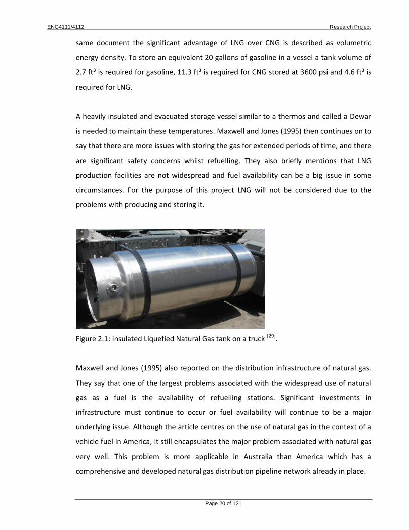
A heavily insulated and evacuated storage vessel similar to a thermos and called a Dewar
is needed to maintain these temperatures. Maxwell and Jones (1995) then continues on to
say that there are more issues with storing the gas for extended periods of time, and there
are significant safety concerns whilst refuelling. They also briefly mentions that LNG
production facilities are not widespread and fuel availability can be a big issue in some
circumstances. For the purpose of this project LNG will not be considered due to the
problems with producing and storing it.
Figure 2.1: Insulated Liquefied Natural Gas tank on a truck [29].
Maxwell and Jones (1995) also reported on the distribution infrastructure of natural gas.
They say that one of the largest problems associated with the widespread use of natural
gas as a fuel is the availability of refuelling stations. Significant investments in
infrastructure must continue to occur or fuel availability will continue to be a major
underlying issue. Although the article centres on the use of natural gas in the context of a
vehicle fuel in America, it still encapsulates the major problem associated with natural gas
very well. This problem is more applicable in Australia than America which has a
comprehensive and developed natural gas distribution pipeline network already in place.

ENG4111/4112 Research Project
Page 21 of 121
2.4 Natural Gas As A Fuel For Combustion Engines
Fortunately natural gas has several aspects which make it appealing as a fuel aside from
cost. These advantages have been reported on many times including by Ingersoll (1996)
who stated natural gas has a very high octane number of around 130, has superior
environmental emissions, and reduced engine wear characteristics to conventional fuels.
Ingersoll’s assessment is of fossil natural gas in America as an alternative vehicle fuel,
however talking about high octane numbers and reduced engine wear is also relevant to
gas turbine engines.
Maxwell and Jones (1995) also reports on the significant increase of thermal efficiency of a
well tuned natural gas engine over a conventionally fuelled engine. This is because of the
high octane number (130) of natural gas, the engine’s compression ratio can be increased
which will increase the overall thermal efficiency.
2.5 Coal Seam Gas
Ingersoll (1996) suggested coal seam gas is an exciting emerging energy source, especially
in Queensland where significant reserves exist. Ingersoll reports that coal bed methane
was generated over long periods of time when organic material is transformed under
pressure to form coal. The significant amount of methane trapped in the coal seams is
held within the coal molecular structure. The book then says that this gas, which was once
considered as a hazard to coal miners, is now recognised as a valuable fuel source. This
reflects the positive change in attitude toward our energy sources over time.

ENG4111/4112 Research Project
Page 22 of 121
2.6 Safety Issues When Working With Natural Gas
Maxwell and Jones (1995) reported that natural gas has been demonstrated to be safe
over the years of operation. This is because of two main reasons: NG is lighter than air so
it dissipates quickly in the event of an accidental spillage, and its ignition point, 1200°F, is
much higher than that of gasoline, 600°F. No burn accidents, other injuries, or fatalities
have been reported during 500 million miles of natural gas vehicle operation (in 1995).
These figures are for natural gas powered vehicles in America, however the natural gas
safety figures are still applicable to all types of natural gas including within Australia.
2.7 Emissions Of Natural Gas Engines
One of the major advantages and selling points of natural gas fuelled engines is the
comparatively low environmental impact due to cleaner exhaust emissions. Maxwell and
Jones (1995) reported that well tuned natural gas engines have exceptionally low
emissions of carbon monoxide, reactive hydrocarbons, and particulate matter. This is
mostly due to the efficient combustion process caused by the methane (CH4) molecules
oxidising with almost no intermediate hydrocarbon constituents. Ideally an engine would
achieve 100% combustion efficiency however in reality the exhaust contains NOx and
particulate matter.
Natural gas engines suffer from high NOx emissions (just as gasoline and diesel engines
do) which are formed as a result of high temperature gas created by the combustion
process reacting with the nitrogen in the intake charge. The NOx emission can contain
non-reacted and partially-reacted fuel due to inefficiencies and cold/hot spots in the
combustion chamber, Nitrous Oxide (NO), Nitrogen Dioxide (NO2), and Sulphur Oxides.
The NOx emissions from any engine can be reduced by exhaust gas recycling (EGR), lean
burn operation, development in fuel mixing and stoichiometric control technology, and a
typical three way catalyst in a combination closed loop exhaust oxygen level feedback.

ENG4111/4112 Research Project
Page 23 of 121
Maxwell and Jones add the principle pollutant from a NG fuelled combustion engine is
unburnt methane which is a result of improper fuel/air ratios and incomplete mixing.
While their discussion specifically relates to NG fuelled reciprocating engines (such as
those found in cars, trucks and buses), emissions and emission controls are still relevant to
gas turbines.
2.8 Stationary Gas Turbine Applications Within Australia
Research has concluded that stationary gas turbines have many applications within
Australia including power generation, co-generation, ships, hovercraft, and
demonstration/test engines.
Sinklair Knight Merz (2007) reported that they were undertaking a project with TRU
energy constructing a 400MW Combined Cycle Gas Turbine (CCGT) Power Station at Yallah
which is situated 13km South of Wollongong in southern NSW.
Sinklair Knight Merz (2007) have also completed a project in conjunction with AGL in
South Australia where the steam and power requirements of Coopers Brewery, Regency
Park, Adelaide have been fulfilled since 2003 by a gas turbine based co-generation plant.
This system was based around a Solar Turbines Centaur 50S gas turbine unit rated at 4.4
MW. This particular turbine is achieving an impressive 8ppm NOx emission thanks to extra
NOx burners which were installed at an extra cost of $200,000.

ENG4111/4112 Research Project
Page 24 of 121
Figure 2.2: Natural gas turbine based co-generation plant by Sinklair Knight Merz [5].
GHD have provided engineering consulting, design and estimation services to many gas
turbine co-generation plants. On the GHD website they outline many different gas turbine
projects which they have provided services for all over Australia. Most of these projects
have served remote communities, mine sites, large industrial manufacturing sites or
refineries and smelters which have particularly high electricity or heat energy demands.
Gas turbines are also utilised in ships and large hovercraft. The Australian Academy of
Scuba Diving website also gives details on the propulsion system of the HMAS Canberra
military destroyer. This ship was powered by two electronically controlled gas turbines
which gave the ship a versatile, responsive and powerful propulsion system (AOS Australia
website). The Hovercraft Homepage also reported that large capacity jet turbine engines
(or in particular gas turbines) were used in large military or commercial hovercraft.
2.9 Manufacturers of Stationary Gas Turbines
For medium to large scale installations most turbine and generator designs are specified
for on a case by case basis and specially ordered. This will ensure the exact needs of the
customer are met and the turbine is not under or over worked to meet the energy
demands. Some small companies however manufacture small scale energy co-generation
plants such as Turbec in Italy. They produce and sell small scale gas turbine based gas

ENG4111/4112 Research Project
Page 25 of 121
turbine based electricity and co-generation plants. One of their products, the T100 CHP
micro-turbine has been successfully manufactured for several years and has clocked
3.617.384 reliable operating hours (Turbec website).
Figure 2.3: Turbec manufactured gas turbine based co-generation plant [30].
2.10 Comparison Of Gas Turbine Engines To Compression Ignition Engines
Mattingly (1996) reported that jet propulsion is a momentum change of a fluid by the
propulsion system. The fluid may be gas used by the engine itself (e.g. turbojet), it may be
a fluid available in the surrounding environment (e.g. air used by a propeller), or it may be
stored in the vehicle and carried by it during the flight (e.g. rocket). These few points
briefly outline jet engines and how they change the kinetic energy of the working fluid to
provide propulsion. This is different to Compression Ignition engines which use the change
in fluid volume by the combustion process (by heat addition) to create mechanical energy.
2.11 Summary
It has been found that coal seam gas is a naturally occurring methane rich gas which is
stored in the molecular structure of underground coal seams. It was formed as organic
matter sitting underground has been transformed to coal over long periods of time and

ENG4111/4112 Research Project
Page 26 of 121
under very high pressures. Coal seam gas was once considered a hazard and hindrance to
coal miners, however with the change in attitude toward energy sources over time it is
now considered a valuable resource.
Natural gas must be stored at very high pressure as Compressed Natural Gas (CNG) or at
very low temperature as Liquefied Natural Gas (LNG). This is because at atmospheric
pressure and temperature natural gas has a very low volumetric energy density and so
would be un-economical to transport and store. Even when natural gas is converted to
CNG or LNG it still has relatively low energy density compared to conventional fossil fuels
so energy density continues to be a major drawback of the technology. Because of these
issues natural gas is mostly transported via piped networks which are very expensive and
difficult to construct.
Natural provides an excellent fuel source for combustion engines for several reasons. It
has been documented that, compared to conventionally fuelled engines, natural gas
engines have lower exhaust emissions of carbon monoxide, reactive hydrocarbons, and
particulates. This is because natural gas has a very high octane number of around 130
which allows for high compression and lean-burn technology to be used on conventional
engines. Natural gas engines however suffer from high NOx emissions mostly consisting of
partially reacted fuel, nitrous oxide, nitrogen dioxide, and sulphur oxides. High NOx
emissions can be dealt with using Exhaust Gas Recycling (EGR), lean burn operation,
development in fuel mixing and stoichiometric control technology, and a typical three way
catalyst in a combination closed loop exhaust oxygen level feedback.
Natural gas safety is a very important factor, and it has been documented that no burn
accidents, other injuries, or fatalities have occurred in America as a result of natural gas
despite more than 500 million miles of natural gas vehicle operation. This is because of
two main reasons: NG is lighter than air so it dissipates quickly in the event of an
accidental spillage, and its ignition point, 1200°F, is much higher than that of gasoline,
600°F.

ENG4111/4112 Research Project
Page 27 of 121
Gas turbine engines operate on similar principles to conventional reciprocating engines
where heat energy from the combustion process expands the working fluid. The
difference however is that gas turbines change the kinetic energy of the working fluid
through a constant combustion process, and then extract energy from the exhaust using a
turbine. This turbine is connected to a compressor wheel which forces more air in the
intake. Conventional reciprocating engines utilise the expanding working fluid in a
controlled volume to move a piston creating mechanical energy.
Stationary gas turbine engines have many applications including energy generation, ship
propulsion, and hovercraft propulsion. More specifically for this report stationary gas
turbine engines are being used more frequently for low to medium scale co-generation
projects. These projects have been most popular in remote communities, mine sites, large
industrial manufacturing sites, refineries, or smelters which have particularly high
electricity or heat energy demands. Most medium scale gas turbine based energy
generation plants are specified and designed on a case by case basis however there are a
several companies manufacturing small generic units and documenting excellent reliability
data.

ENG4111/4112 Research Project
Page 28 of 121
Chapter 3 – Coal Seam Gas Industry
3.1 Introduction
This chapter will firstly go over a brief industry overview including an explanation why Coal
Seam Gas is undergoing a period of such rapid growth, the areas where Coal Seam Gas is
located in Queensland, and an estimate of the quantity of attainable Coal Seam Gas in
Queensland. A brief overview of existing natural gas distribution infrastructure will then
be provided followed by a cost analysis of different fuels.
3.2 Industry Overview
With ever increasing environmental pressure and supplies of conventional fossil fuels past
the peak supply, and exponentially increasing demand the price has been rising. It was
anticipated that this price rise would promote a change in attitude toward the use of
these fuels however household budgets have adopted to the price increase and demand
has continued to exponentially grow. There will be a point however where the cost of
these fuels reaches a point where it is too expensive to use crude oil based products in the
current fashion. At this point alternate energy sources will be required to fulfil the
requirements of our developed energy intensive western lifestyle.
It is widely accepted that when this occurs renewable energy sources will be the long-term
solution for our energy needs. Ideally the transition to renewable energy sources could
begin immediately however the technology suffers from several problems. Some of these
include low natural energy density available for collection, inability to provide peak power
at times of high demand without an energy storage system, highly energy intensive
equipment construction, and associated high cost. Development of these technologies is
making unprecedented progress, however at the current level of technological
development they are not a viable alternative for large scale main-stream energy
generation. These issues will certainly be addressed by technological advances in the
upcoming years and renewable energy sources will prevail as the energy source of choice,
however in the interim period an alternative energy source needs to be implemented.

ENG4111/4112 Research Project
Page 29 of 121
Because of this the natural gas industry (especially in Queensland) is going through a
period of unprecedented growth and development.
Coal Seam Gas can be produced wherever coal seams are present. For economic reasons
however the accessibility which includes coal seam depth, soil/rock type, and the
surrounding water table are all important considerations when analysing the extraction
process. In Queensland Coal Seam Gas is currently produced from the Surat and Bowen
basins however coal seams also exist in the Cooper, Clarence Moreton, and Galilee basins.
Figure 3.1: Major Coal basins in Queensland [17].
Domestic natural gas consumption in Australia is rising, and is expected to be around 1750
Petajoules by 2020 [17]. The following graph shows the natural gas consumption trend, and
projected trend.

ENG4111/4112 Research Project
Page 30 of 121
Table 3.1: Australian natural gas consumption [17].
Increasing domestic natural gas consumption will increase the feasibility of natural gas as
an alternative fuel. This will promote an increase in investment of distribution
infrastructure and therefore providing the fuel to more areas at a cheaper rate.
Natural gas exports are expected to rise significantly in 2013 when several large LNG
projects will be complete in Gladstone on the central Queensland coast. There are eight
proposed coal seam gas projects worth in excess of $40 billion. These projects propose an
annual gas production of 50 million tonnes of LNG from over 8600 wells piped to
liquification plants in Gladstone and mostly exported [21].

ENG4111/4112 Research Project
Page 31 of 121
Some of the current project proposals which are currently in place in Queensland are:
Santos Ltd/Petronis proposes to construct an LNG plant near Gladstone along with a
450km pipeline.
Queensland Gas Company (QGC) proposes to construct an LNG plant near Gladstone along
with a 430km pipeline.
LNG Limited/Arrow proposes to construct an LNG plant near Gladstone.
ConocoPhillips/Origin Energy proposes to construct an LNG plant near Gladstone.
Shell (CSG) Australia Pty Ltd proposes to construct an LNG plant near Hamilton Point.
Sojitz Corporation proposes to construct an LNG plant near Gladstone.
Impel (Southern Cross LNG) proposes to construct an LNG plant near Gladstone along with
a 400km pipeline.
Energy World Corporation proposes to construct an LNG plant at Abbott Point.
Most of these projects are aimed at LNG production on the mid Queensland coast, and
exportation. Unfortunately at the time of writing there was no information on projects
developing the distribution infrastructure within metropolitan areas of Australia.

ENG4111/4112 Research Project
Page 32 of 121
3.2.1 Existing Distribution Infrastructure
As discovered in the background research, due to the low energy density of natural gas,
transporting the fuel by road tanker is rarely feasible. Therefore the largest issue with
natural gas is the distribution of the fuel. Assessing the infrastructure shortfalls is an
important aspect of this project. The installation of small to medium scale gas turbine co-
generation plants around industrial and suburban areas (such as those proposed in this
project) must be assessed on a case by case basis. Essential factors which will make or
break the feasibility of the project is the heat energy demands of the area and especially
the shortfalls of the natural gas pipelines. If the station will be situated 20m from an
existing pipeline then the project may be feasible, however if it is 12 km through a
metropolitan area then the cost of laying the pipe may outweigh any benefits the plant
can offer.
Because of this need for individual case analysis to assess the feasibility of the project,
then this report cannot make conclusions on individual cases without receiving further
specific information, however an analysis of existing infrastructure will be conducted.
Major Queensland natural gas transmission lines include:
The Roma to Brisbane Pipeline (RBP) from Wallumbilla (Roma) to Brisbane (438
km) [16]
The South West QLD Pipeline (SWQP) from Ballera to Wallumbilla (Roma) (756 km)
[16]
The Queensland Gas Pipeline (QGP) from Wallumbilla (Roma) to Gladstone and
Rockhampton (627.1 km) [16]

ENG4111/4112 Research Project
Page 33 of 121
The Carpentaria Gas Pipeline (CGP) from Ballera to Mt Isa (840 km) [16]
The North QLD Pipeline (NQGP) from Moranbah to Townsville (391 km) [16]
These pipelines are designed to transport natural gas from the field to large industrial
customers, local distribution networks, and also natural gas power plants. In addition to
these pipelines the Queensland - South Australia - New South Wales pipeline was
commissioned in 2009, and the Queensland Hunter Gas Pipeline was approved for
construction in early 2009. Both of these pipelines will link the top 4 above pipelines with
large customers south of the border further powering the Queensland natural gas
economy.
Localised gas distribution networks fed from the above transmission lines are located in
Brisbane, the Gold Coast, Toowoomba, Ipswich, Dalby, Roma, Oakey, Bundaberg,
Maryborough, Gladstone, Rockhampton, and Hervey Bay [16].
3.3 Natural Gas Cost Analysis
The costs associated with coal seam gas production can vary greatly depending on the
source location, type of terrain, geological makeup of the soil, distance from source to
point of use, and the tariffs on the pipelines used. Some of these costs can commonly
include:
Geological area analysis
Exploratory drilling
Securing land access
Drilling production wells
Compressing the gas

ENG4111/4112 Research Project
Page 34 of 121
Treatment of CSG well water
Pipeline tariffs
These costs can be subject to change, and other costs can also occur depending on the
circumstances.
Despite the above costs one of the major advantages of natural gas over conventional
fossil fuels is said to be the price. Gastech in Melbourne have quoted the price of natural
gas to be $0.38/m3 (Baxter, R 2010, pers. comm., 2 June) at atmospheric pressure.
Currently this gas is a blend of conventional natural gas and CSG. Predicting the cost of
CSG in Queensland when it becomes available in a pure form is impossible however it is
said to be similar to the above figure.
From the above quoted figure and using atmospheric pressure (P0psi ) as 101.325 kPa
P0psi V0psi = P3600psi V3600psi
101325× 1 = 2.48×10⁷× V3600psi
V3600psi = 4.086 Litres
Therefore the cost of CNG per litre = $0.38/4.086 = $0.093/L
The approximate cost of LNG was now needed to successfully compare relative fuel prices
and was quoted by Westfarmers as $0.48 per litre (Hazel, B 2010, pers. comm., 3 June).
With this information the following table can be completed.
ENG4111/4112 Research Project
Page 35 of 121
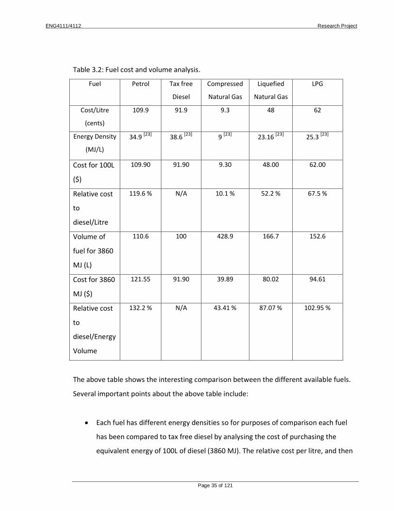
Table 3.2: Fuel cost and volume analysis.
Fuel Petrol Tax free
Diesel
Compressed
Natural Gas
Liquefied
Natural Gas
LPG
Cost/Litre
(cents)
109.9 91.9 9.3 48 62
Energy Density
(MJ/L)
34.9 [23] 38.6
[23] 9 [23] 23.16
[23] 25.3
[23]
Cost for 100L
($)
109.90 91.90 9.30 48.00 62.00
Relative cost
to
diesel/Litre
119.6 % N/A 10.1 % 52.2 % 67.5 %
Volume of
fuel for 3860
MJ (L)
110.6 100 428.9 166.7 152.6
Cost for 3860
MJ ($)
121.55 91.90 39.89 80.02 94.61
Relative cost
to
diesel/Energy
Volume
132.2 % N/A 43.41 % 87.07 % 102.95 %
The above table shows the interesting comparison between the different available fuels.
Several important points about the above table include:
Each fuel has different energy densities so for purposes of comparison each fuel
has been compared to tax free diesel by analysing the cost of purchasing the
equivalent energy of 100L of diesel (3860 MJ). The relative cost per litre, and then

ENG4111/4112 Research Project
Page 36 of 121
per energy volume has then been provided for purposes of comparison.
The above prices and price comparisons do not include transport/delivery costs, or
costs of installing specialised CNG lines which could dramatically affect the above
figures.
Each of the above fuel prices were attained at the time of writing, and were either
local average fuel price, or quoted prices for conventional natural gas in
Melbourne at the time of writing.
3.4 Conclusion
This chapter aimed at increasing the scope of the analysis of CSG by looking at an industry
overview, where CSG is located, and how much of it can be reasonably extracted. An
overview of existing natural gas distribution infrastructure was then provided followed by
a cost analysis of different fuels.
Coal Seam Gas (CSG) is going through a un-precedented period of growth due to the push
for alternative energy sources while development of renewable energy generation
technology advances to a point where it can be widely used. In Queensland there are
eight proposed coal seam gas projects worth in excess of $40 billion. These projects
propose an annual gas production of 50 million tonnes of LNG from over 8600 wells piped
to liquification plants in Gladstone and mostly exported. This is causing significant interest
and investment in the technology, and it will provide a significant boost to employment
and to the Queensland economy.
CSG is sourced from anywhere that underground coal seams exist. In Queensland Coal
Seam Gas is currently produced from the Surat and Bowen basins however coal seams
also exist in the Cooper, Clarence Moreton, and Galilee basins.
ENG4111/4112 Research Project
Page 37 of 121
Natural gas consumption is expected to rise over the upcoming years mostly due to the
export projects stated above, and also the continued development and consumption of
natural gas domestically.
Major Queensland gas distribution pipelines were briefly summarised and local
distribution networks in Brisbane, the Gold Coast, Toowoomba, Ipswich, Dalby, Roma,
Oakey, Bundaberg, Maryborough, Gladstone, Rockhampton, and Hervey Bay were
identified.
The costs of natural gas production were then outlined and a costing analysis of different
fuel types was conducted. Because of the different energy content per volume the fuels
cannot be directly compared using the cost per litre. The energy content had to be
employed to compare these fuels per contained energy volume. It was discovered that
natural gas purchase was 43.41 % that of diesel per energy volume. This will be a very
important tool in summarising the feasibility of CSG as an alternative fuel in later chapters.

ENG4111/4112 Research Project
Page 38 of 121
Chapter 4 – Consequential Effects
In this chapter the consequential effects of the work conducted in this project will be
reviewed. To help in this analysis the ‘Engineering Frameworks for Sustainability’
published by the Institution of engineers Australia will be used.
4.1 Sustainability
Sustainability is becoming an issue of great significance in modern society. If a new
technology is introduced (such as CSG in gas turbines) the environmental and
sustainability aspects will be key issues which will need to be closely assessed.
Sustainability of the technology can be assessed using the ‘Towards Sustainable
Engineering Practice: Engineering Frameworks for Sustainability’, Institution of engineers,
Australia, Canberra, 1997. This document outlines ten aspects of sustainability, some of
which have relevance to this project.
1. Development today should not undermine the development and environmental
needs of future generations. – This project certainly has an impact on the use
of finite resources which are not renewable. It is however using the finite
resource CSG instead of crude oil based products. Crude oil based products are
still commonly used despite knowledge of their lack of sustainability, and
substituting their use in some areas such as fuels is going to help the existing
crude oil reserves last longer for our future generations. CSG has potential
uses in fuels and domestic gas supplies so using it for gas turbines is a good
application. Australia and in particular Queensland has extensive reserves of
CSG so using a domestic energy source also saves on inter-continental
transportation of energy.

ENG4111/4112 Research Project
Page 39 of 121
2. Environmental protection shall constitute an integral part of the development
process. – Environmental protection is another important aspect of assessing
alternative fuels. Most environmental protection issues lay with gas
exploration, extraction, transportation, and exhaust emissions once burnt. A
detailed analysis of the environmental issues with extraction, transport, and
storage are beyond the scope of this report however they are still important
and should be considered closely by the energy supplier. Initial research
suggests that emissions are much more favourable whilst burning CSG as
opposed to other crude oil based fuels.
3. Engineering people should take into consideration the global environmental
impacts of local actions and policies. – Development of CSG technology would
lead to a spread of CSG use all over the world which would decrease reliance
on crude oil, decrease running costs, create new jobs, and save significant
environmental emissions.
4. The precautionary approach should be taken – scientific uncertainty should not
be used to postpone the measures to prevent environmental degradation –
CSG is a new and emerging technology which has some big advantages over
crude oil based fuels. An approach to a new technology such as CSG should be
approached proactively instead of the general rule of caution. The advantages
of this technology should be realised and development should be pushed
forward to make it happen as soon as possible. The environmental benefits of
NG have been documented many times over and action toward technological
development, documentation of results, and community awareness needs to
be taken.
5. Environmental issues should be handled with the participation of all concerned
citizens. – All citizens in western societies will be affected by the reduced
reliance on crude oil based products. A significant reduction of environmental
emissions by energy production and significant saving to transportation from
converting engines to run on CSG will be seen.
6. The community has a right of access to, and an understanding of,
environmental issues. – All sections in this project have been structured in

ENG4111/4112 Research Project
Page 40 of 121
such a way that all environmental aspects, results, and conclusions are readily
accessible and easily understood.
7. The polluter should bear the cost of pollution and so environmental costs
should be internalised by adding them to the cost of production. – All potential
pollution costs are assumed to be the responsibility of the energy provider
because it is assumed that they will occur in the CSG exploration, extraction,
and transportation stages of the process. All environmental emissions from
burning CSG have been determined to meet all regulations.
8. The eradication of poverty, the reduction in differences in living standards and
the full participation of women, youth and indigenous people are essential to
achieve sustainability. - This project has no impact on diversity, racism, ageism,
or sexist issues. It is likely to bring money to remote communities where
indigenous ratios are quite high, which could be used toward helping local
issues.
9. People in developed countries bear a special responsibility to assist in the
achievement of sustainability. – If CSG was to spread all over the world the
benefit to both developed and un-developed communities would be equal.
Developed communities would receive a reliable source of energy which has
low price variation, requires minimal modification to existing infrastructure,
and is more environmentally friendly. Due to the nature of CSG it is spread all
over the world so un-developed countries would benefit by selling the gas
which would help their economies, create jobs, and develop political
relationships with other countries.
10. Warfare is inherently destructive of sustainability, and, in contrast, peace,
development and environmental protection are interdependent and indivisible.
– CSG is located all over the world and is not necessarily in high concentrations
where the demand is located. This will promote international trading between
countries. Over history this has proven to be both beneficial and a significant
hindrance to worldwide political relationships. It would be hoped that only
positive relationships between countries would develop from trading CSG but
that is nearly impossible to accurately predict.

ENG4111/4112 Research Project
Page 41 of 121
4.2 Ethical Responsibility
Any engineering activity has ethical responsibility which is assumed by the
conductor of the activity. A large portion of this particular project is risk free (the
research) however it is important to conduct the research ethically. Another portion
of the project being final assembly of the model engine, and operation of the engine
to gain experimental data has significant health and safety issues associated with it.
Considering this, a review of the Engineers Australia Code of Ethics was necessary
for some guidance on how to conduct this task ethically. Upon review Tenets 2, 4,
and 7 of the Engineers Australia Code of Ethics were chosen as relevant to this task
and are as follows:
2. Members shall act with honour, integrity and dignity in order to merit the trust
of the community and the profession.
4. Members shall act with honesty, good faith and without discrimination toward
all in the community.
7. Members shall express opinions, make statements or give evidence with
fairness and honesty and only to the basis of adequate knowledge.
After reading these guidelines it was concluded that two essential guidelines must
be adhered to when completing this project. The first is to conduct research with
honour, integrity, and dignity. This meant that work was written to the best of the
available knowledge and also truthfully. Also all work had to be correctly referenced
with careful citation to the information source in order to give the original authors
due credit for their work. The second guideline was that the risks associated with
conducting the work with my model had to be managed as best as possible. This is
covered in the next section and also appendix A.

ENG4111/4112 Research Project
Page 42 of 121
4.3 Natural Gas as a Fuel
Safety issues of using natural gas as a fuel are very important in this project. Natural gas
has been found to be lighter than air so it dissipates quickly in the event of an accidental
spillage. This is a good property in the case of an accidental leak as the gas will quickly
dissipate minimising risk to surrounding personnel. Natural gas also has an ignition point
of 1200°F which is much higher than that of gasoline, 600°F so a much better ignition
source is required to ignite the fuel.
4.4 Safety Issues
It was decided that the best risk management procedure was to complete risk
assessments for all activities being conducted to minimise the possibility of something
going wrong. There are essentially two major activities which have been risk assessed and
these are general assembly and soldering, and running the engine to gain experimental
results. These assessments are attached respectively in Appendix A.

ENG4111/4112 Research Project
Page 43 of 121
Chapter 5 – Gas Turbine History and Principles of Operation
5.1 Introduction
Combustion engines operate using a working fluid (mostly air) and subject it to process
which allow the engine to extract energy from it. This chapter briefly looks at the history
of gas turbines and the general principles which allow combustion engines to successfully
operate. It then looks at the basic layout of a simple cycle gas turbine engine and
summarises the cycles occurring and the components involved.
5.2 Gas Turbine Origins
Experimentation into gas turbine engines began in the 1930’s and it took several years
until the design was refined enough to build the first practical engine for service in 1940.
Design issues that stunted the expansion of the gas turbine in the early stages of
development were lack of hi-tech materials capable of withstanding the high
temperatures and velocities of the turbine blades, and low combustor and compressor
efficiencies. These issues were improved over time and the expansion of gas turbine
engines into service has seen an exponential growth since.
5.3 Basic Engine Cycles
In all heat (combustion) engines there are cycles which represent each process of
operation. In most engines these cycles are adiabatic compression (1-2), heat addition (2-
3), adiabatic expansion (3-4), and heat rejection (4-1) as illustrated in the diagram below.

ENG4111/4112 Research Project
Page 44 of 121
Figure 5.1: The Brayton cycle.
5.4 Principles of Operation
The simple cycle gas turbine engine has several essential components to ensure the basic
thermodynamic cycles can occur and the engine can operate successfully. The basic
components are outlined below.
Figure 5.2: The simple cycle gas turbine layout.

ENG4111/4112 Research Project
Page 45 of 121
The thermodynamic cycles occurring in a simple cycle gas turbine include:
1. Intake – the working fluid is accelerated through the intake by the compressor from
quiescent ambient conditions to a velocity at the compressor inlet.
2. Compression – working fluid then undergoes reversible adiabatic compression by
the compressor wheel of the turbocharger usually within a pressure ratio of 4 to 1
to 15 to 1. This air is then forced through piping into the intake of the combustion
chamber.
3. Heat addition – the fuel is then injected in the first part of the combustion chamber
and the working fluid undergoes heat addition at constant pressure.
4. Expansion - the heated working fluid then undergoes reversible adiabatic expansion
in the second part of the combustion chamber. This high velocity stream of gases
flows over the turbine of the turbocharger which in turn drives the compressor
wheel.
5. Exhaust – heat is then rejected from the working fluid at constant pressure through
the exhaust system beyond the turbine.
Gas turbine engine can exist in both axial and radial flow layout. In axial flow engine the
working fluid flows from the compressor in an axial direction to the engine shaft. Most
commercially produced engines are of this design to minimise losses in the working fluid
path. Simple cycle gas turbine engine based on automotive turbochargers however are
radial flow (ie. the working fluid flows from the compressor in a direction perpendicular to
the engine shaft). A diagram of such engines is provided below.

ENG4111/4112 Research Project
Page 46 of 121
Figure 5.3: A radial flow simple cycle gas turbine engine based on a turbocharger.
5.5 Conclusion
The model test apparatus developed in the following chapter must successfully achieve
the thermodynamic cycles outlined in this chapter. The basic design of the engine is
known and further analysis and design justification is in the following chapter.
ENG4111/4112 Research Project
Page 47 of 121
Chapter 6 – Model Design and Construction
Objectives
The objective of this chapter is to design and construct a model gas turbine engine to run
on a gaseous fuel and gain experimental results to aid in the analysis of Coal Seam Gas as
an alternative stationary jet fuel.
6.1 Introduction
This chapter firstly aims to analyse the design constraints and requirements of the model
gas turbine engine which will be constructed for this project. The processes of a simple
cycle gas turbine will then be revised before the conceptual design process is started.
Design requirements and expected results will be used as criteria when refining the
conceptual design. A successful conceptual design will be judged on the ability to provide
the desired results once constructed. Once the concept is refined a 2-D conceptual jet
design will be drafted on AutoCAD which will include more detailed dimensions. A 3-D
model will then be created of the combustion chamber in order to undertake CFD analysis
and get a better understanding of how the engine works in areas a that could not
otherwise be seen. Once these drawings and models are complete the process of materials
selection, creating a cutting list, and construction can begin. Once the jet is complete
experimental work will be carried out and parameters such as fuel consumption, exhaust
temperature, and combustion chamber pressure will be measured and recorded for
further analysis. Finally the design and construction process will have a full appraisal and
any future work and design changes will be noted.

ENG4111/4112 Research Project
Page 48 of 121
6.2 Design Requirements & Constraints
The design requirements of an engineering project are guidelines which outline the
direction and parameters of the system design process.
These include:
1. The engine must operate reliably enough to attain the desired results
This report is based on the analysis of coal seam gas as an alternative stationary jet
fuel. The purpose of the model is to achieve experimental data on gas fuel
consumption and calculate thermal efficiency of the model to aid in the reflection
of the jet design process conducted in this report. It is essential that the engine is
reliable enough to attain these results. Despite this engine being of primitive design
and construction, and also having a relatively low expected thermal efficiency it will
still be a good tool to aid in the analysis of CSG as an alternative fuel.
2. The engine must be compact and portable
The engine must be constructed and transported from storage sites to test areas
which may be significant distances apart. The engine is also expected to spend
some time in the university engine test labs (not for operation but simply storage
and minor modifications). Because of these two factors the engine must be
compact and portable. Moving the jet on a removalist trolley from location to
location would be ideal. For this reason the jet will be constructed within an outer
frame and all associated components will be housed within this exo-skeletal
structure.

ENG4111/4112 Research Project
Page 49 of 121
3. There must be built in safety systems to reduce risk
Safety is an essential factor in any engineering project and this project is no
exception. There is significant danger involved in the operation of a model jet such
as the design being considered for this project. The turbocharger on which this jet
is based on is being used in such a way that it was never designed for whilst the
engine is achieving very high temperatures and very high turbocharger shaft
speeds. Three essential steps will be undertaken to increase the safety of this
model. The first is to install and exhaust temperature sensor close to the exhaust
turbine of the turbocharger. This will be monitored during operation, and the
engine will be shut down if the temperature rises above a selected point. The
second is to make an exclusion zone in the exhaust of the jet to prevent any
bystanders from being struck from any debris whilst in operation. The last is to
conduct a risk assessment of the operation of the jet to minimise any potential
risks.
The design constraints of an engineering project are limitations which outline the direction
and parameters of the system design process. It is possible for a design to address all of
the design requirements but not satisfy the constraints, so it is important to consider these
in the design process.
These include:
1. The engine must be manufactured for less than $1000 (excluding labour)
The engine design and construction process must be kept in perspective for this
project. Building a model jet which costs $20,000 and takes 1 year to manufacture
is beyond the scope of this project. In the case of a gas turbine the extra expense

ENG4111/4112 Research Project
Page 50 of 121
will only achieve greater thermal efficiency which will not benefit the outcome of
the experimental process.
2. All manufacturing process must be conducted by myself
For the purpose of proper model analysis it was decided that all manufacturing was
to be conducted using no machining processes. At the time of construction such
machines were not available, and getting machining professionally done would
quickly exceed the project budget. Therefore all construction was done using a
welder, angle grinders, and other basic tools.
3. The Combustion chamber must be designed for the turbocharger
For this particular project a suitable turbocharger had already been sourced so the
combustion chamber on this particular engine was to be built around this device.
For this reason detailed turbocharger selection details will not be included but a
brief overview can be seen in section 6.4.1.
Now the requirements and constraints of the design are known the design process can
begin.
6.3 System Processes
The simple cycle gas turbine engine this model will be based on will have the same cycles
as outlined in section 5.3. This design relies on the turbocharger to provide a compressor
and turbine, and the intake, combustion chamber, and exhaust will be constructed. Each
of these processes is essential to the operation of the engine, so these cycles will be used
in the design analysis and final design selection process.

ENG4111/4112 Research Project
Page 51 of 121
6.4 Conceptual Design Analysis
For this model engine the most essential part of construction is the correctly sized design
of the combustion chamber for the selected turbocharger. The combustion chamber will
therefore be designed, and the rest of the engine layout will be built around it.
6.4.1 Turbocharger Considerations
If the combustion chamber is to be built around the selected turbocharger then turbo
selection is less important. There are several steps to take to ensure successful operation
of the model engine. These are:
1. Ensuring the turbocharger is in healthy working condition by checking for chips on
the compressor and turbine wheels, and feeling for axial shaft play.
2. Choosing the turbocharger for the desired engine size.
3. Ensuring the turbocharger is not out of budget.
For this particular project a Garrett GT 4082 journal bearing turbocharger was chosen for
use. This turbocharger has a compressor inducer diameter of 58 mm and a high flow
capacity.
This turbocharger was chosen mainly because it was available at a low cost at the time of
the build, and also its large size and high flow capacity would allow a larger engine to be
built. This particular turbocharger also has an internal wastegate for its intended
application on a compression ignition engine on a bus. This device is used to control boost
levels in these engines and will be disabled as it is of no use in an engine of this design.

ENG4111/4112 Research Project
Page 52 of 121
6.4.2 Combustion Chamber Design
This section will look at some basic background theory of combustion chamber design
specifically in the purpose and design of the combustion liner, and also measures to
improve the efficiency of the system.
The combustion chamber of a gas turbine engine introduces fuel to the compressed
working fluid and, ideally, achieves efficient combustion. Minimising heat and pressure
loss within the combustion chamber is essential in maximising the thermal efficiency of the
system.
Realistically the combustion chamber will have heat and pressure loss which will decrease
the thermal efficiency of the system. As a solution the outer wall of the combustion
chamber will be constructed from relatively thick material to minimise heat flow to the
atmosphere.
A combustion chamber can be designed to minimise the excess air passing through the
system (say around 10-20%) which would also increase the thermal efficiency of the
system. Unfortunately however certain parts of the turbine cannot operate at the elevated
temperatures that would be produced by operating an engine in this way.
Consequently a successful combustion chamber design must make careful allocation of a
significant portion of the working fluid to the dilution and cooling of the combustion gases
before they hit the turbine. This is achieved by dividing the compressed working fluid into
two streams, the primary and secondary flows. The primary flow is subject to heat addition
via fuel injection and ignition. The secondary flow is then progressively introduced to the
primary flow lowering the outlet temperature of the combustion chamber and completing
the combustion process.

ENG4111/4112 Research Project
Page 53 of 121
For this style of jet engine the primary flow is separated from the secondary flow using a
combustion liner inside the combustion chamber. This liner is around half the diameter of
the outer wall of the combustion chamber and has holes drilled in it to allow only a portion
of the air to mix with the fuel. More drawings and discussion of this liner will be provided
later in the report.
For engines of this design the combustion chambers have been found to be much larger
diameter than the size of the turbine inlet on the exhaust housing of the chosen
turbocharger. For this reason there will have to be a transition area to force the mixed
post combustion working fluid into the entrance of the turbine. This transition area must
be carefully designed to minimise head loss from sharp orifice like pathways for the
working fluid. The combustion chamber will be gradually reduced in diameter at an angle
of no greater than 20 degrees measured from the axis of the combustion chamber.
6.4.3 Combustion Chamber Sizing
As mentioned previously the sizing of the combustion chamber to the turbocharger is
essential. If the combustion chamber is too small the engine will have a low thermal
efficiency and may not reach full throttle because of flow restrictions. If the combustion
chamber is too large the working fluid velocity may not be high enough to attain proper
combustion and the engine may overheat and prematurely suffer turbine failure.
The essential measurement for combustion chamber sizing is the inducer diameter which
was previously stated as 58mm. As this is expected to be the smallest area through which
all the working fluid must pass it is essential that no part of the system have a smaller
diameter than this. The combustion chamber construction will also be heavily dictated by
the available material and construction constraints such as access for welding and
minimising heat loss in heat affected areas.

ENG4111/4112 Research Project
Page 54 of 121
In the design process of the finalised combustion chamber the GR1 combustor formula
attached in appendix D was used as a rough guide to pipe sizes. This formula was found in
the research process and has been written by the website author Don Giandomenico after
many projects similar to the one proposed in this report. It was decided that this formula
would give an appropriately accurate component sizing guide for the context of this
report.
6.4.4 Combustion Chamber Pipe Work Layout
This section will analyse the purpose and requirements of the pipe work carrying the
compressed working fluid from the compressor outlet to the intake of the combustion
chamber. Ideally these engines will have minimal pipe work between the heat addition
process and the turbine to minimise frictional losses of the high speed gases. For this
reason most combustion chambers in engines of this simple cycle design are bolted
directly to the turbochargers turbine. The pipe work then provides the link between the
compressor outlet and the top of the combustion chamber which sits perpendicular to the
turbocharger shaft.
As stated above the smallest diameter allowed for primary pipe work is 58mm so all pipe
work will be a minimum of 2.5 inch (63.5mm) diameter.
The pipe work would therefore start at the compressor outlet and be welded into the top
of the combustion chamber. In order to increase symmetry and efficiency of the fuel
mixing and post combustion cooling the intake pipe would be split, and feed into the top
of the combustion chamber on opposite sides. This will decrease ‘cold spots’ in the
combustion chamber where effective mixing does not occur and combustion is incomplete
of non-existent. The pipes will also be set into the combustion chamber with an offset to
create a whirlpool swirling like effect of the gases within the combustion chamber.

ENG4111/4112 Research Project
Page 55 of 121
6.4.5 Combustion Liner Design
The combustion chamber liner is an essential component to the success of a gas turbine
engine design. The purpose and reasoning behind this has been covered in section (6.4.2.).
This section of the report will cover the sizing of the liner, and also the size and placement
of the holes allowing the separation of the primary working fluid flow.
A successful combustion chamber liner must:
1. Contain all fuel injection and ignition components
2. Separate the working fluid into primary flow and secondary flow
3. Achieve an approximate 1:4 primary to secondary flow ratio
4. Successfully mix the secondary with the primary flow post combustion
Achieving these criteria means there are several essential aspects of design which must be
accurate to the criteria. The combustion liner must have an appropriate diameter such
that there is sufficient room for a fuel injector and spark plug in the top, there is sufficient
room for successful and non-restricted combustion to take place, and there is sufficient
room for the secondary flow to bypass the liner and mix with the primary flow post
combustion.
Primary and secondary fluid flow separation is achieved by creating an area for the
primary fluid flow to enter the combustion liner. This is nominally achieved by drilling
evenly spaced holes in the liner. The number and size of the holes is carefully controlled to
ensure their total area is 20% of the compressor inducer area.

ENG4111/4112 Research Project
Page 56 of 121
The total inducer area is Ai = x (di/2)2
Ai = x (58/2)2
Ai = 2642.08 mm2
Assuming constant working fluid velocity (V1), the volumetric flow rate (Q1) is related
directly to the area (A1) through
The actual working fluid velocity however will be significantly less than that at the inducer.
This is because the area which the working fluid has to flow through increases significantly
upon entrance to the combustion chamber. Estimating the total combustion liner hole
area (AB) of around 20% of the inducer area will therefore suffice. Combustion chamber
testing will ensure successful separation of primary and secondary flow of the ratio and
complete combustion is occurring before the gases are exposed to the turbine.
AB = 528.42 mm2
These approximate dimensions have also been taken from the GR1 combustor formula
talked about in chapter 6.4.3 and shown in appendix D.
6.4.6 Afterburner design
For an afterburner to successfully work on an engine of this design it must make a seal
around the exhaust outlet from the turbocharger and allow the exhaust velocity to slow
slightly. This is done by increasing the flow area (or pipe/duct diameter) and introducing
fuel through a secondary injector which combusts utilising the remaining oxygen from the

ENG4111/4112 Research Project
Page 57 of 121
secondary flow within the combustion chamber. The flow must then be restricted post
combustion to increase the velocity of the working fluid.
6.5 Materials Selection
Given all the above design parameters and the available material at the time of
construction the following materials have been selected for the combustion chamber:
Primary combustion chamber shell – It has been discussed that the combustion
chamber will have a thick primary shell to minimise the heat energy losses to the
surrounding environment before the turbine. Because of this 5 inch (127 mm) thick
walled mild steel pipe was chosen for its availability and heat retention capability.
Combustion liner - No information was available at the time of construction on the
sizing of the combustion liner however many pictures were available on existing
combustion liners. The available material was assessed and 3 inch (76.2 mm) thin
walled mild steel exhaust pipe was chosen. With a liner this size there would be
adequate room to drill holes for separating the primary and secondary flow, and
also for the secondary flow to bypass the liner and mix with the primary flow
before the turbine.
Pipe work – As stated earlier all pipe work will be 2.5 inch (63.5 mm) diameter to
avoid flow restriction to the compressed working fluid. All pipe work within 200mm
of the combustion chamber will be 2.5 inch thick walled steel steam pipe bends to
aid in the construction of the bends, for ease of welding, and also for heat
retention. All other pipe work will be thin walled mandrel bent exhaust pipe.
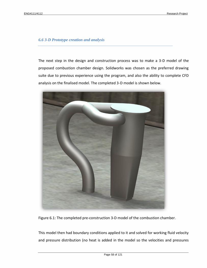
ENG4111/4112 Research Project
Page 58 of 121
6.6 3-D Prototype creation and analysis
The next step in the design and construction process was to make a 3-D model of the
proposed combustion chamber design. Solidworks was chosen as the preferred drawing
suite due to previous experience using the program, and also the ability to complete CFD
analysis on the finalised model. The completed 3-D model is shown below.
Figure 6.1: The completed pre-construction 3-D model of the combustion chamber.
This model then had boundary conditions applied to it and solved for working fluid velocity
and pressure distribution (no heat is added in the model so the velocities and pressures

ENG4111/4112 Research Project
Page 59 of 121
post combustion will be inaccurate). The boundary conditions were set at a uniform
velocity of 100m/sec in the inlet and atmospheric pressure at the outlet. The results are as
follows:
Figure 6.2: Pressure distribution within the 3-D model

ENG4111/4112 Research Project
Page 60 of 121
Figure 6.3: Velocity distribution within the 3-D model
These plots, especially the velocity, show how effective the combustion liner is separating
the flow of gases by minimising the velocity within the combustion liner. A majority of the
flow bypasses the combustion liner and effectively mixes with the primary flow post
combustion. No obvious flow restrictions or high pressure points exist so model
construction can begin.

ENG4111/4112 Research Project
Page 61 of 121
6.7 Cutting List
Based on the above materials, construction of the combustion chamber could begin. The
following table is a list of materials used in this process.
Table 6.1: Initial costing of the combustion chamber construction
Component Material Length/quantity Source Cost
Main Shell 5 inch MS pipe 350 mm Off cut from steel supplies
$5.00
Liner 3 inch MS exhaust pipe
230 mm Exhaust shop $10.00
Pipe Bends 2.5 inch 90° steam pipe bends
6 Steel supplies $6.95 each
Thin Walled Pipe
2.5 inch exhaust pipe
600 mm Exhaust shop $15.00
Chamber Cap 6mm MS plate 85 mm radius circle
Supplied $0.00
Bolts M8x35mm Zinc plated
8 Bolt shop $15.95
Fuel Injector Modified countersunk brass
orifice
1 Hose supplies $1.95
Spark Plug NGK B8S 1 Automotive shop
$4.95
Welding Materials
Welding gas, wire, shield, glove
- Supplied $0.00
Angle Grinders 5 and 9 inch grinders with
grinding, cutting, and flap disc
wheels to suit
- Supplied $0.00
Oxy-acetylene Torch
Oxygen, acetylene, wand,
glasses
- Supplied $0.00
Paint High temperature enamel in a can
1 Paint store $14.95
From this table it can be seen that the total construction cost (not including labour) of the
combustion chamber is $94.50. As planned the construction process on the rest of the jet
can now be costed.
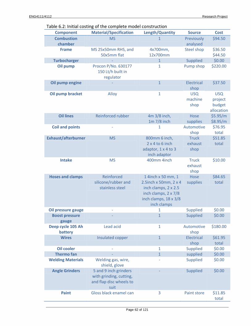
ENG4111/4112 Research Project
Page 62 of 121
Table 6.2: Initial costing of the complete model construction Component Material/Specification Length/Quantity Source Cost
Combustion chamber
MS 1 Previously analysed
$94.50
Frame MS 25x50mm RHS, and 50x5mm flat
4x700mm, 12x700mm
Steel shop $36.50 $44.50
Turbocharger - 1 Supplied $0.00 Oil pump Procon P/No. 630177
150 Lt/h built in regulator
1 Pump shop $220.00
Oil pump engine - 1 Electrical shop
$37.50
Oil pump bracket Alloy 1 USQ machine
shop
USQ project budget
allocation Oil lines Reinforced rubber 4m 3/8 inch,
1m 7/8 inch Hose
supplies $5.95/m $8.95/m
Coil and points - 1 Automotive shop
$76.95 total
Exhaust/afterburner MS 800mm 6 inch, 2 x 4 to 6 inch
adaptor, 1 x 4 to 3 inch adaptor
Truck exhaust
shop
$51.85 total
Intake MS 400mm 4inch Truck exhaust
shop
$10.00
Hoses and clamps Reinforced silicone/rubber and
stainless steel
1 4inch x 50 mm, 1 2.5inch x 50mm, 2 x 4
inch clamps, 2 x 2.5 inch clamps, 2 x 7/8
inch clamps, 18 x 3/8 inch clamps
Hose supplies
$84.65 total
Oil pressure gauge - 1 Supplied $0.00 Boost pressure
gauge - 1 Supplied $0.00
Deep cycle 105 Ah battery
Lead acid 1 Automotive shop
$180.00
Wires Insulated copper 1 Electrical shop
$61.95 total
Oil cooler - 1 Supplied $0.00 Thermo fan - 1 supplied $0.00
Welding Materials Welding gas, wire, shield, glove
- Supplied $0.00
Angle Grinders 5 and 9 inch grinders with grinding, cutting, and flap disc wheels to
suit
- Supplied $0.00
Paint Gloss black enamel can 3 Paint store $11.85 total

ENG4111/4112 Research Project
Page 63 of 121
From this table it can be seen that the total construction cost (not including labour) of the
model jet is $943.00. This falls within the specified budget and so is deemed a successful
construction plan.
Table 6.3: Initial experimental apparatus cost
Component Length/quantity Source Cost
9kg LPG gas bottle
1 BBQ supplies $39.95
Garden leaf blower
1 supplied $0
It can be seen from the above tables that the construction process has been costed within
the prescribed budget so construction can now begin.
6.8 2-D Prototype Engineering Construction Drawings
Engineering construction drawings were now produced to aid in the construction of both
the combustion chamber and the combustion liner (see appendix E).
6.9 Construction
This section of the report will go through the steps taken in the construction process.
These steps are as follows:
1. Gather all specified construction materials

ENG4111/4112 Research Project
Page 64 of 121
2. Construct combustion chamber including combustion liner, fuel injector, and spark
plug
3. Attach combustion chamber to the turbocharger
4. Build an appropriately dimensioned frame (exact dimensions unimportant)
5. Build mounts on the frame for the turbocharger and the combustion chamber
6. Install jet onto frame
7. Construct exhaust and afterburner and attach
8. Install oil system including pump, motor, cooler, thermo fan, and lines
9. Add a dash panel and install all gauges
10. Complete all wiring and install battery
11. Touch up all painted surfaces
Each step will now be explained in further detail as to the method used
Step 1: Gather all specified construction materials
The first step in the construction process was to gather all specified construction materials
in the above tables for ease of work once construction had begun. Fortunately all materials
were sourced from local suppliers so this process was relatively easy, and was complete
within a day.

ENG4111/4112 Research Project
Page 65 of 121
Step 2: Construct combustion chamber including combustion liner, fuel injector, and spark
plug
It was decided earlier in this chapter that the most crucial component to the success of the
engine, the combustion chamber, would be constructed first with all proceeding pieces
fabricated to work in conjunction with it.
The first step in this process was to modify the lower half of the 5 inch pipe such that it
converges to a square outlet the same size as the turbine inlet on the turbocharger (73 x
50 mm). To do this, 4 wedges were cut axially along opposing sides of the pipe, and the
pipe was worked into the desired shape using a 12 pound sledge hammer. This was the
seam welded, ground off, and buffed with a flap disc. The combustion liner was then cut to
a length such that there was adequate bypass area for the secondary flow between the
liner and the shell. The liner was then welded to the cap and bolted to the top of the pipe
forming a removable lid in the combustion chamber. The pipe work was tacked into place
to match the 3D model and fully welded. All welds were then cleaned with a 5 inch grinder
and flap disc, and the whole assembly was painted to avoid corrosion.
Figure 6.4: Side view of the completed combustion chamber

ENG4111/4112 Research Project
Page 66 of 121
Figure 6.5: Top view of the completed combustion chamber
Figure 6.6: Side view of the completed combustion liner

ENG4111/4112 Research Project
Page 67 of 121
Figure 6.7: Top view of the completed combustion liner with fuel and spark inlet
Step 3: Attach combustion chamber to the turbocharger
The combustion chamber was then bolted to the turbocharger.
Step 4: Build an appropriately dimensioned frame (exact dimensions unimportant)
It was now time to build an appropriately dimensioned frame to house the jet and all
associated components for operation (excluding the LPG bottle). When considering the
layout of the components an important factor is the position of perishable components or
flammable liquids in relation to hot surfaces. For this reason it was decided to mount the
jet horizontally on top of a rectangular frame. This would also help with the oil drain of the
turbocharger which needs to freely drain away. A frame was therefore constructed from
available 25 x 50 RHS and 50 x 6 flat bar to appropriate dimensions for the application.
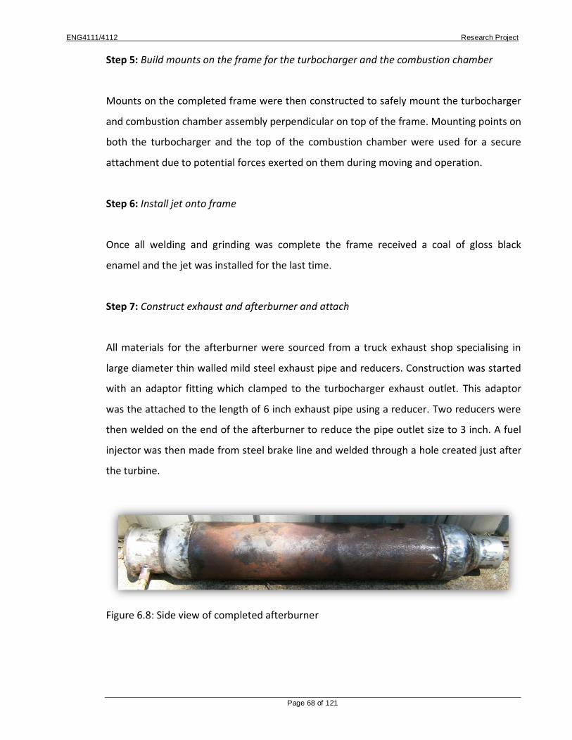
ENG4111/4112 Research Project
Page 68 of 121
Step 5: Build mounts on the frame for the turbocharger and the combustion chamber
Mounts on the completed frame were then constructed to safely mount the turbocharger
and combustion chamber assembly perpendicular on top of the frame. Mounting points on
both the turbocharger and the top of the combustion chamber were used for a secure
attachment due to potential forces exerted on them during moving and operation.
Step 6: Install jet onto frame
Once all welding and grinding was complete the frame received a coal of gloss black
enamel and the jet was installed for the last time.
Step 7: Construct exhaust and afterburner and attach
All materials for the afterburner were sourced from a truck exhaust shop specialising in
large diameter thin walled mild steel exhaust pipe and reducers. Construction was started
with an adaptor fitting which clamped to the turbocharger exhaust outlet. This adaptor
was the attached to the length of 6 inch exhaust pipe using a reducer. Two reducers were
then welded on the end of the afterburner to reduce the pipe outlet size to 3 inch. A fuel
injector was then made from steel brake line and welded through a hole created just after
the turbine.
Figure 6.8: Side view of completed afterburner

ENG4111/4112 Research Project
Page 69 of 121
Figure 6.9: Top view of the completed afterburner showing secondary fuel injection
Step 8: Install oil system including pump, motor, cooler, thermo fan, and lines
The oil system is a crucial component of the successful and reliable operation of the
turbocharger. The chosen oil pump was a rotary vane pump with inbuilt and adjustable
pressure regulator (see appendix B for full specifications). This pump was mounted on a
custom fabricated bracket and powered by a 12 V electric motor via a belt drive. This
system was installed along with the drain line from the turbocharger, intake line, filter, and
appropriate connection for the oil gauge line.

ENG4111/4112 Research Project
Page 70 of 121
Figure 6.10: Belt driven oil pump apparatus
Step 9: Add a dash panel and install all gauges
A simple dash panel was created from some scrap aluminium checker plate in which
gauges and switches would be mounted within. The switches installed would control the
power to the oil pump, and also power to the thermo fan mounted on the oil cooler. The
gauges installed include oil intake pressure, combustion chamber pressure, and exhaust
temperature.
Figure 6.11: Dash with installed control switches and gauges

ENG4111/4112 Research Project
Page 71 of 121
Step 10: Complete all wiring and install battery
All wiring was now to be completed including installing the ignition system. The chassis of
the engine was grounded directly to the negative terminal of the battery and all positive
power lines were wired through switches if appropriate. The ignition coil was secured in a
non heat-affected area using cable ties and the lead was run to the spark plug.
Step 11: Touch up all painted surfaces
Once all construction was completed all painted surfaces were touched up, wiring was
secured with cable ties, and the model was ready to run.

ENG4111/4112 Research Project
Page 72 of 121
Figure 6.12: Completed model apparatus ready for testing
6.10 Conclusion
The design and construction has been an initial success with the model being complete on
time and within budget. Upon initial inspection the engine seems to adhere to the
specified design requirements and constraints however a full design appraisal for this
model will be conducted after the end of the testing in chapter 7.

ENG4111/4112 Research Project
Page 73 of 121
Chapter 7 – Small Engine Performance
7.1 Introduction
As stated in section 1.3, the second aim of this project was to develop a small scale gas
turbine engine which will be used to attain experimental data to aid in making conclusions
about CSG as an alternative fuel. The previous chapter has extensively covered the
construction process, so this chapter will cover the experimental testing process and
provide attained test data, and basic calculations.
7.2 Aims and Objectives
The aims of an engineering experimental test procedure have both general aspects, and
also project related aspects. The general aspects include:
Be conscious of risks as outlined in the risk assessment (appendix A)
Complete all activities with respect to the environment
Act in an ethical and professional manner
Ensure all results are as accurate as possible to what is occurring
Some more specific aims are:
Attain all desired results

ENG4111/4112 Research Project
Page 74 of 121
Maintain a constant watch on engine vitals including oil pressure and especially
exhaust temperature to minimise risk of a catastrophic failure
Ensure test apparatus does not allow the fuel supply to come in contact with heat
These experimental aims are important considerations when planning the test apparatus
and procedure to ensure the completion of the experiment safely and successfully.
7.3 Test Apparatus
With these aims in mind an experimental apparatus can be designed such that all
experimental aims, specifically safety, are fulfilled by the experimental procedure. Given
the nature of this type of engine safety of all operators and on-lookers will be the first
priority. With this in mind the following points must be adhered to:
All flammable substances including lubricating oil and fuel must be kept as far
away as practically possible from all heat and ignition sources
All persons must stay out of an exclusion zone in the exhaust stream and a 45
degree tangent from it (see below diagram)
All on-lookers must stay at least 10 metres away from the operating engine in all
other directions (see below diagram)
Only essential persons are allowed within these exclusion zones and these people
must wear personal protection equipment
There are several measures taken to ensure the above points are implemented. An
appropriate exclusion zone is outlined. No one including the operators are allowed in the

ENG4111/4112 Research Project
Page 75 of 121
exhaust exclusion zone due to the risk of flying debris, and only essential operators
including the starter in the start procedure, and the fuel flow control and engine vital
monitoring person are allowed in this area. The fuel supply (an LPG bottle) is kept away
from all heat and ignition sources by a 2 metre long supply line (see below diagram).
Figure 7.1: Test apparatus.
To address the more specific experimental aims outlined in the previous chapter the
exhaust temperature will be monitored with a thermocouple temperature meter capable
of reading very high temperatures (an EMTEK EMT-502 provided by the USQ Faculty of
Engineering). The combustion chamber pressure and lubricating oil pressure will be
monitored with an automotive boost gauge mounted on the dash panel of the model
engine. The fuel supply (LPG bottle) will also be mounted on electronic scales to compare
the change in mass with time. This will provide a fuel mass flow rate which will be useful
in future calculations.
7.4 Test Procedure

ENG4111/4112 Research Project
Page 76 of 121
On the day of the experiment the following plan was outlined for the experimental
procedure to ensure the safety and success of the procedure:
1. Decide on an appropriate location to test the apparatus.
2. Carefully transport all test apparatus and associated components to the chosen
location.
3. Set up the engine in an orientation such that the exhaust fumes and smoke will not
affect any of the surrounding structures of wildlife.
4. Outline specified exclusion zones with orange safety cones.
5. Set up electronic scales in a location on the intake side of the engine and at a
distance such that the length of the fuel feed line will be fully utilised.
6. Sit LPG bottle onto scales and connect to the fuel line.
7. Have a discussion with all operators and on-lookers to ensure there is a clear
understanding of the exclusion zones, and plan the sequence of starting events
with the starter.
8. Connect the battery.
9. Turn on the oil pump and monitor the rise and stabilisation of oil pressure to the
turbocharger.
10. Have the starter start the leaf blower and align with the engine intake.

ENG4111/4112 Research Project
Page 77 of 121
11. Apply full power to the leaf blower, turn on fuel slowly whilst pressing the ignition
button repeatedly and wait to hear a ‘pop’ sound which signifies the start of the
combustion process.
12. With the leaf blower still attached and on full power, slowly increase the supply of
the fuel and listen to the engine turbine speed which will sound like a high pitched
whine.
13. Throttle the engine up to a point where the leaf blower is no longer needed (the
starter will know this because the leaf blower engine revs will increase as the
turbine sucks air through the device and takes load off the engine).
14. Remove the leaf blower and adjust fuel supply to maintain a steady idle speed.
15. Take a reading of the mass of the LPG bottle and start the stopwatch.
16. Run the engine for the desired period of time (60 seconds was appropriate on this
test day) and then take another reading of the LPG cylinder mass.
17. The fuel mass flow rate will be the change of mass divided by the time taken.
18. Repeat this fuel measuring procedure for a variety of throttle settings including full
throttle and record all data.
19. Ensure exhaust temperature and oil pressure is monitored throughout the entire
test and shut the engine down immediately if these readings fall above or below
pre-specified thresholds.
20. Once all tests are complete shut the fuel supply down to the engine to stop the
combustion process.

ENG4111/4112 Research Project
Page 78 of 121
21. Keep the oil pump running for several minutes after shut down to help cool the
turbocharger bearings.
22. After this time turn the oil pump off, disconnect the battery and LPG cylinder and
pack all test apparatus away being very careful of hot surfaces.
Following these procedures, actioning the risk assessments and utilising common sense
would increase the chance of a successful and safe experiment. These points were
adhered to on an initial test day and the outcomes of this day are outlined below.
7.5 Results
On the day of the experiment the above procedure was followed and the results recorded
at the lowest throttle setting required to maintain operation.
The data recorded is as follows:
The LPG mass changed from 16.3 kg to 15.5 kg in 8 minutes of total operation
The surrounding temperature on the day was 15°C
The average exhaust temperature was 530°C
The average combustor pressure was 3.75 psi
As discussed in the previous chapter results from a variety of throttle settings were
required however premature turbine failure due to a lack of oil supply resulted in the test

ENG4111/4112 Research Project
Page 79 of 121
being incomplete (see section 7.7 for further analysis). Despite this unfortunate failure,
analysis on the recorded data can still be conducted.
The process of analysis of a gas turbine engine assumes steady flow of the working fluid
(air) during each of the operating cycles. The gas turbine relies on energy addition to the
working fluid by an external source (fuel) and other variables are also assumed constant
or are neglected such as pressure loss in the combustor, and change of working fluid
specific heat between compression and exhaust.
7.6 Thermal Efficiency Calculation
From the experimental data the change in internal energy (U) could be found from
reducing the steady state flow energy equation.
The Steady State Energy Equation is given by:
Because there is no input heat energy (Q), or input work (W) then these values are zero.
Also there is no change in mass flow rate (m), or potential energy (Z) from the intake to
the exhaust of the engine so these values can be neglected. There is also no input energy
to the system (U1) so this value is zero. The Steady State Energy Equation is reduced to:

ENG4111/4112 Research Project
Page 80 of 121
Where
= Input heat energy (Joules)
= Input work (Joules)
= Mass flow rate of the working fluid (kg/sec)
= Input energy to the system (Joules)
= Output energy of the system (Joules)
= Input potential energy to the system (Joules)
= Output potential energy of the system (Joules)
= Input enthalpy to the system (Joules)
= Output enthalpy of the system (Joules)
g = Gravitational acceleration (m/sec2)
Cpair = Specific Heat (J/kg.K)

ENG4111/4112 Research Project
Page 81 of 121
T∞ = Surrounding outside air temperature (°C)
Tout = Exhaust outlet temperature (°C)
To find output energy (U2) the inlet and outlet temperature (T∞ and Tout respectively) of
the running engine was required. The surrounding temperature (T∞) was taken with a
thermometer and a thermocouple attached to an EMTEK EMT-502 receiver was placed in
the exhaust stream to find the Tout.
Therefore:
T ∞ = 15 oC
Tout = 530 oC
= 0.8 kg in 8 mins
= 1.67 x 10⁻³ kg/sec
Joules
(note the absolute value of U2 is used when taking the square root)
It can be said the system work (W) is the change in energy of the system.
Therefore
Cpair is sourced from Principles
of Heat Transfer[11] in table
A26. It is read as 1012 J/kg.K at
20oC and 1076 J/kg.K at 500oC.
Because these values are
different an average will be
taken.

ENG4111/4112 Research Project
Page 82 of 121
W = ∆U
We know
U1 = 0
So
W = U2 = 1036.98 Joules
We know thermal efficiency is the ratio of work output over heat energy within the
supplied fuel[13]. This efficiency shows the amount of energy contained in the consumed
fuel that is actually converted to power. This efficiency is expected to be quite low due to
the nature of the engine however the results will still be useful to get a comparative CSG
fuel consumption.
Therefore
Where
LCV = Lower Calorific Value (J/kg)
W = System work (Joules)
Qin = Input heat energy (Joules)
The LCV of LPG has been found as 45.8 x 10⁶ J/kg [12]
Therefore

ENG4111/4112 Research Project
Page 83 of 121
From this stage the comparative CSG fuel consumption can be calculated assuming similar
burn characteristics and similar thermal efficiency.
We know
=
The LCV of CSG has been found as 38.7 x 10⁶ J/kg [12]
kg/sec
For comparative purposes this mass flow rate equates to 0.9504 kg of fuel in 8 minutes
compared to the 0.8 kg of LPG in the same time. This figure is an increase of 18.8 % fuel
consumption compared to LPG.

ENG4111/4112 Research Project
Page 84 of 121
This comparison of fuel consumption by mass is of limited use in the analysis of CSG. This
figure must be converted to volumetric fuel consumption to be of any use.
The density of LPG is 1.882 kg/m3, and CSG is 0.8 kg/m3 [15].
Where
Q = Volumetric flow rate (m3/sec)
= Mass flow rate (kg/sec)
= Gas density (kg/m3)
Therefore the volumetric flow rate (Q) of each fuel is found to be:
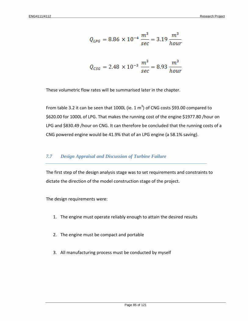
ENG4111/4112 Research Project
Page 85 of 121
These volumetric flow rates will be summarised later in the chapter.
From table 3.2 it can be seen that 1000L (ie. 1 m3) of CNG costs $93.00 compared to
$620.00 for 1000L of LPG. That makes the running cost of the engine $1977.80 /hour on
LPG and $830.49 /hour on CNG. It can therefore be concluded that the running costs of a
CNG powered engine would be 41.9% that of an LPG engine (a 58.1% saving).
7.7 Design Appraisal and Discussion of Turbine Failure
The first step of the design analysis stage was to set requirements and constraints to
dictate the direction of the model construction stage of the project.
The design requirements were:
1. The engine must operate reliably enough to attain the desired results
2. The engine must be compact and portable
3. All manufacturing process must be conducted by myself

ENG4111/4112 Research Project
Page 86 of 121
The design constraints were:
1. The engine must be manufactured for less than $1000 (excluding labour)
2. There must be built in safety systems to reduce risk
3. The Combustion chamber must be designed for the turbocharger
The success of this design will be how well it reflects these design requirements and
constraints. If the design does not satisfy one or more of these criteria then the design
process has partially failed and the process must be reflected to assess when the error
occurred.
The first design requirement, reliability, is an important factor of the finished model.
Despite this upon initial testing of the model engine unfortunately the turbocharger has
suffered a premature failure of the exhaust wheel and bearing (see below pictures). This
failure has been traced to a leaking oil seal in the turbocharger which caused abnormally
high lubricating oil consumption. This eventually used the 2L of oil in the reservoir and
while the engine was operating the oil pump ran dry. Lubricating oil is essentially
important for the bearings of a turbocharger so this failure caused significant wear on the
bearing which allowed slight play in the shaft causing the exhaust wheel to come into
contact with the exhaust housing damaging it. This failure was caused by two factors. The
first was the defective seals in the turbocharger, and the second was the lack of oil level
monitoring built into the design. It was assumed that if the oil level was checked between
every run then a monitoring system was not needed. This turned out to be un-true and the
failure of the system is partially a result of that.

ENG4111/4112 Research Project
Page 87 of 121
Figure 7.2: Close up of turbocharger turbine wheel pre-failure
Figure 7.3: Close up of turbocharger turbine wheel post-failure (note chips on blade edges)

ENG4111/4112 Research Project
Page 88 of 121
The second requirement, compactness and portability, was deemed important for storage
and transportation reasons. This was achieved well in the design process. The frame is
large and heavy enough to resist movement at full engine throttle but compact enough to
be moved by one person easily.
The third and final requirement, all manufacturing work to be completed by myself, was
also completed successfully with the exception of one piece. All welding and construction
of the frame and combustion chamber, the wiring, and the plumbing was completed by
myself as per the requirements. The oil pump bracket however was manufactured by the
USQ machine shop. During the construction process it was decided that the accuracy of
the belt drive and pump mount was essential for the stability of the oil supply. This could
be done under the project budget allocation from the university and so would not affect
the project budget. Despite this action being against one of the design requirements it was
well worthwhile upon reflection.
The first specified design constraint was the model had to be manufactured for less than
$1000. As specified in the costing and cutting lists earlier in this chapter the construction
process was completed within this budget so the construction process was a success in
relation to this point.
The second specified restraint was the inclusion of safety systems to minimise the risk to
the operator and by standers during engine operation. Because of this an exhaust
temperature monitoring device was installed to monitor the temperature of the exhaust. If
the temperature rose beyond a pre-determined threshold the engine would be shut down
to reduce the risk of premature failure. The lack of oil monitoring causing the previously
discussed failure will be considered a safety failure due to the obvious safety concerns if
the turbine was to fail at full throttle.
In summary, most design requirements and restraints were achieved successfully. An
exception to this was the lack of lubrication oil level monitoring which partially contributed
to a premature turbine failure and was therefore considered a safety risk. Another

ENG4111/4112 Research Project
Page 89 of 121
exception was the oil pump bracket which was manufactured by the USQ machine shop
against one of the design requirements. This was however an important decision which did
not affect any other requirements including the project budget. Because of this it will not
be considered a failure in the design and construction process.
7.8 Conclusion
The testing procedure for the model set out to cover the experimental testing process and
provide attained test data, and basic calculations.
The test apparatus was designed in such a way as to minimise risk to experimental
operators and on-lookers by thinking about the possible causes of failure, and taking
precautionary measures to minimise the risk of these occurring. In the design of the
exclusion and restriction zones outlined in figure 7.1, the potential dangers to operators
and on-lookers was also predicted and danger areas were outlined as a result of this. All
activities were also conducted in a professional and ethical manner, and also with respect
to the environment.
The experiment was carried out according to the test procedure outlined in section 7.3.
During this experiment the engine was started and all measurements taken for one
throttle setting. Once this period was over the oil pressure of the lubricating oil was
observed to be rapidly dropping. The engine was promptly shut down however
permanent damage to the turbocharger has occurred as a result of this. The turbine
failure was as a result of excessively high oil consumption in the final minutes of operation
most likely due to failed oil seals within the turbocharger.
It was also concluded that the final model engine design did not have an oil level
monitoring system built in which would have allowed the operator to monitor the oil level

ENG4111/4112 Research Project
Page 90 of 121
and potentially shut the engine down before failure. This failure has resulted in the model
and testing procedure failing to meet some of the outlined requirements.
When conducting the design of the model a design requirement was that ‘The engine
must operate reliably enough to attain the desired results’. These required results were at
a variety of throttle settings which was not fulfilled by the testing procedure. An aim of
the testing procedure was also to ‘Attain the desired results’ which was also not
completed. Despite this, future work on this model can repair the turbocharger and
conduct further tests to attain the initially desired results.
From the obtained results however initial analysis of the data was conducted resulting in
some very interesting conclusions. The thermal efficiency of the model engine was
calculated to be 1.356 %. This figure is, despite appearances, a very acceptable figure for a
home built model engine. Despite the relatively low thermal efficiency the calculations
using results produced by this engine will still provide an accurate indication of the
relative CSG fuel consumption and running cost.
The equivalent fuel consumption of CSG was then calculated, and both mass flow rate fuel
consumptions were converted to volumetric fuel consumptions using the gas densities.
Using table 3.2 it was observed that from the possessed data 1000L (ie. 1 m3) of CNG costs
$93.00 compared to $620.00 for 1000L of LPG. The running cost of the engine was then
calculated to be $1977.80 /hour on LPG and $830.49 /hour on CNG.
These results produced a running cost saving of 58.1% for CNG over LPG. This result is an
excellent conclusion for the case of CNG as an alternative fuel. 58.1% is a significant
margin for saving and would produce significant saving in electricity which could be
passed on to the consumer.
It must be said however that gas turbine based electricity generation plants do not
commonly operate on LPG and ideally a comparison of CSG running costs to Jet A1 (a
common petroleum based jet fuel), or kerosene would be conducted. It was however

ENG4111/4112 Research Project
Page 91 of 121
concluded that the evaporation and injection system required for a liquid fuelled gas
turbine would dramatically affect the performance so it would not be accurate to compare
these fuels to LPG in the way that CSG has been compared with LPG. This is maybe an
excellent place for future work to be conducted on this project.

ENG4111/4112 Research Project
Page 92 of 121
Chapter 8 – Project Conclusion
8.1 Introduction
This section of the report aims to conclude the findings of the work completed in this
project, reflect on what objectives were outlined for this project and how effective the
work has been in achieving these objectives, and outline any future work to be completed
for this project.
8.2 Summary
This project essentially had two essential facets both aimed at assessing Coal Seam Gas
(CSG) as an alternative fuel for power generation using gas turbine based co-generation
plants. The first facet of this project was aimed at finding out what CSG is, where it comes
from, and also what distribution infrastructure existed. The second facet was to develop a
test engine from which experimental results could be attained to aid in the overall
conclusion of the suitability of CSG as an alternative fuel.
Research into background information relating to CSG found it is a naturally occurring
methane rich gas which is stored in the molecular structure of underground coal seams. It
was formed as organic matter sitting underground has been transformed to coal over long
periods of time and under very high pressures. CSG was once considered a hazard and
hindrance to coal miners, however with the change in attitude toward energy sources
over time it is now considered a valuable resource.
This research also concluded that natural gas at atmospheric pressure and temperature
has very low volumetric energy density and so would be un-economical to transport and
store. Because of this natural gas must be stored at very high pressure as Compressed

ENG4111/4112 Research Project
Page 93 of 121
Natural Gas (CNG) or at very low temperature as Liquefied Natural Gas (LNG). Even when
natural gas is converted to CNG or LNG it still has relatively low energy density compared
to conventional fossil fuels so energy density continues to be a major drawback of the
technology. Because of these issues natural gas is mostly transported via piped networks
which are very expensive and difficult to construct.
Natural gas poses as an excellent fuel source for combustion engines due to several
reasons. It has been documented that, compared to conventionally fuelled engines,
natural gas engines have lower exhaust emissions of carbon monoxide, reactive
hydrocarbons, and particulates. This is because natural gas has a very high octane number
of around 130 which allows for high compression and lean-burn technology to be used on
conventional engines. Natural gas engines however suffer from high NOx emissions mostly
containing partially reacted fuel, nitrous oxide, nitrogen dioxide, and sulphur oxides. High
NOx emissions can be dealt with using Exhaust Gas Recycling (EGR) ), lean burn operation,
development in fuel mixing and stoichiometric control technology, and a typical three way
catalyst in a combination closed loop exhaust oxygen level feedback.
Natural gas safety is a very important factor, and it has been documented that no burn
accidents, other injuries, or fatalities have occurred in America as a result of natural gas
despite more than 500 million miles of natural gas vehicle operation. This is because of
two main reasons: NG is lighter than air so it dissipates quickly in the event of an
accidental spillage, and its ignition point, 1200°F, is much higher than that of gasoline,
600°F.
The analysis of the CSG industry was deemed to be very important for the overall
conclusion of the project. CSG is locations within Queensland were summarised, and
attainable quantities of the gas in Queensland was also researched to scope the analysis.
An overview of existing natural gas distribution infrastructure was then provided followed
by a cost analysis of different fuels.

ENG4111/4112 Research Project
Page 94 of 121
From this analysis Coal Seam Gas (CSG) was found to be going through a un-precedented
period of growth due to the push for alternative energy sources while development of
renewable energy generation technology advances to a point where it can be widely used.
In Queensland there are eight proposed coal seam gas projects worth in excess of $40
billion. These projects propose an annual gas production of 50 million tonnes of LNG from
over 8600 wells piped to liquification plants in Gladstone and mostly exported. This is
causing significant interest and investment in the technology, and it will provide a
significant boost to employment and to the Queensland economy.
The CSG sources in Queensland Coal Seam Gas have been found to be from the Surat and
Bowen basins however coal seams also exist in the Cooper, Clarence Moreton, and Galilee
basins.
Natural gas consumption is expected to rise over the upcoming years mostly due to the
export projects stated above, and also the continued development and consumption of
natural gas domestically.
Major Queensland gas distribution pipelines have been briefly summarised and local
distribution networks in Brisbane, the Gold Coast, Toowoomba, Ipswich, Dalby, Roma,
Oakey, Bundaberg, Maryborough, Gladstone, Rockhampton, and Hervey Bay were
identified.
The costs of natural gas production were then outlined and a costing analysis of different
fuel types was conducted. Because of the different energy content per volume the fuels
cannot be directly compared using the cost per litre. The energy content had to be
employed to compare these fuels per contained energy volume. It was discovered that
natural gas purchase was 43.41 % that of diesel per energy volume.

ENG4111/4112 Research Project
Page 95 of 121
With this initial information the project was at a stage where further analysis required
experimental fuel consumption so the focus turned to gas turbine engines. It was found
that gas turbine engines operate on similar principles to conventional reciprocating
engines where heat energy from the combustion process expands the working fluid. The
difference however is that gas turbines change the kinetic energy of the working fluid
through a constant combustion process, and then extract energy from the exhaust using a
turbine. This turbine is connected to a compressor wheel which forces more air in the
intake. Conventional reciprocating engines utilise the expanding working fluid in a
controlled volume to move a piston.
Stationary gas turbine engines have been found to have many applications including
energy generation, ship propulsion, and hovercraft propulsion. More specifically for this
report stationary gas turbine engines are being used more frequently for low to medium
scale co-generation projects. These projects have been most popular in remote
communities, mine sites, large industrial manufacturing sites, refineries, or smelters which
have particularly high electricity or heat energy demands. Most medium scale gas turbine
based energy generation plants are specified and designed on a case by case basis
however there are a few companies manufacturing small generic units and documenting
excellent reliability data.
The thermodynamic cycles of a simple cycle gas turbine engine were outlined and it was
concluded that the basic design of the model engine must allow these cycles to occur.
The first step of the design analysis stage was to set requirements and constraints to
dictate the direction of the model construction stage of the project.

ENG4111/4112 Research Project
Page 96 of 121
The design requirements were:
1. The engine must operate reliably enough to attain the desired results
2. The engine must be compact and portable
3. All manufacturing process must be conducted by myself
The design constraints were:
1. The engine must be manufactured for less than $1000 (excluding labour)
2. There must be built in safety systems to reduce risk
3. The Combustion chamber must be designed for the turbocharger
The success of this design was analysed on how well it reflected these design requirements
and constraints. The first design requirement, reliability, was placed as an important factor
of the finished model. Despite this upon initial testing of the model engine unfortunately
the turbocharger has suffered a premature failure of the exhaust wheel and bearing. This
failure has been traced to a leaking oil seal in the turbocharger which caused abnormally
high lubricating oil consumption. This eventually used the 2L of oil in the reservoir and
while the engine was operating the oil pump ran dry. Lubricating oil is essentially
important for the bearings of a turbocharger so this failure caused significant wear on the
bearing which allowed slight play in the shaft causing the exhaust wheel to come into
contact with the exhaust housing damaging it.
This failure was caused by two factors. The first was the defective seals in the
turbocharger, and the second was the lack of oil level monitoring built into the design. It
was assumed that if the oil level was checked between every run then a monitoring system

ENG4111/4112 Research Project
Page 97 of 121
was not needed. This turned out to be un-true and the failure of the system is partially a
result of that.
The second requirement, compactness and portability, was deemed important for storage
and transportation reasons. This was achieved well in the design process. The frame is
large and heavy enough to resist movement at full engine throttle but compact enough to
be moved by one person easily.
The third and final requirement, all manufacturing work to be completed by myself, was
also completed successfully with the exception of one piece. All welding and construction
of the frame and combustion chamber, the wiring, and the plumbing was completed by
myself as per the requirements. The oil pump bracket however was manufactured by the
USQ machine shop. During the construction process it was decided that the accuracy of
the belt drive and pump mount was essential for the stability of the oil supply. This could
be done under the project budget allocation from the university and so would not affect
the project budget. Despite this action being against one of the design requirements it was
well worthwhile upon reflection.
The first specified design constraint was the model had to be manufactured for less than
$1000. As specified in the costing and cutting lists earlier in chapter 6 the construction
process was completed within this budget so the construction process was a success in
relation to this point.
The second specified restraint was the inclusion of safety systems to minimise the risk to
the operator and by standers during engine operation. Because of this an exhaust
temperature monitoring device was installed to monitor the temperature of the exhaust. If
the temperature rose beyond a pre-determined threshold the engine would be shut down
to reduce the risk of premature failure. The lack of oil monitoring causing the previously
discussed failure will be considered a safety failure due to the obvious safety concerns if
the turbine was to fail at full throttle.

ENG4111/4112 Research Project
Page 98 of 121
The testing procedure for the model set out to cover the experimental testing process and
provide attained test data, and basic calculations.
The test apparatus was designed in such a way as to minimise risk to experimental
operators and on-lookers by thinking about the possible causes of failure, and taking
precautionary measures to minimise the risk of these occurring. In the design of the
exclusion and restriction zones outlined in figure 7.1, the potential dangers to operators
and on-lookers was also predicted and danger areas were outlined as a result of this. All
activities were also conducted in a professional and ethical manner, and also with respect
to the environment.
The experiment was carried out according to the test procedure outlined in section 7.3.
During this experiment the engine was started and all measurements taken for one
throttle setting. Once this period was over the oil pressure of the lubricating oil was
observed to be rapidly dropping. The engine was promptly shut down however
permanent damage to the turbocharger has occurred as a result of this. The turbine
failure was as a result of excessively high oil consumption in the final minutes of operation
most likely due to failed oil seals within the turbocharger. It was also concluded that the
final model engine design did not have an oil level monitoring system built in which would
have allowed the operator to monitor the oil level and potentially shut the engine down
before failure. This failure has resulted in the model and testing procedure failing to meet
some of the outlined requirements.
Most design requirements and restraints were achieved successfully. However when
conducting the design of the model a design requirement was that ‘The engine must
operate reliably enough to attain the desired results’. These required results were at a
variety of throttle settings which was not fulfilled by the testing procedure. An aim of the
testing procedure was also to ‘Attain the desired results’ which was also not completed.
Despite this, future work on this model can repair the turbocharger and conduct further
tests to attain the initially desired results.

ENG4111/4112 Research Project
Page 99 of 121
From the obtained results however initial analysis of the data was conducted resulting in
some very interesting conclusions. The thermal efficiency of the model engine was
calculated to be 1.356 %. This figure is, despite appearances, a very acceptable figure for a
home built model engine. Despite the relatively low thermal efficiency the calculations
using results produced by this engine will still provide an accurate indication of the
relative CSG fuel consumption and running cost.
The equivalent fuel consumption of CSG was then calculated, and both mass flow rate fuel
consumptions were converted to volumetric fuel consumptions using the gas densities.
Using table 3.2 it was observed that from the possessed data 1000L (ie. 1 m3) of CNG costs
$93.00 compared to $620.00 for 1000L of LPG. The running cost of the engine was then
calculated to be $1977.80 /hour on LPG and $830.49 /hour on CNG.
These results produced a running cost saving of 58.1% for CNG over LPG. This result is an
excellent conclusion for the case of CNG as an alternative fuel. 58.1% is a significant
margin for saving and would produce significant saving in electricity which could be
passed on to the consumer.
8.3 Conclusion
From the work conducted in this project a preliminary conclusion about CSG as an
alternative fuel source would be that it is feasible.
From the background research into CSG it was discovered that there is existing
distribution infrastructure which connects the gas supply with localised networks in
almost every major city in Queensland. The fuel usage and proposed projects are seen to
be increasing at a very high rate which will increase the distribution infrastructure by
attracting investment. Further analysis of CSG showed that there are real benefits in
environmental emissions, thermal efficiency, and the fuel cost per energy volume was

ENG4111/4112 Research Project
Page 100 of 121
43.41 % for CNG compared to that of diesel. This shows significant benefits in converting
to CSG, and may financially and environmentally outweigh the installation of application
specific infrastructure (ie. expensive fuel pipelines to each individual site).
A model gas turbine engine has also been developed to assist in making conclusion about
CSG. Despite suffering a premature failure in the early stages of the experimental process
preliminary experimental data has been collected and analysed. These results produced a
running cost saving of 58.1% for CNG over LPG for this style of engine. This was deemed a
significant margin of saving and is an exceptionally strong argument toward CSG even
without the previously said benefits.
In conclusion CSG has been found to exist in Queensland in significant and easily
attainable quantities. The benefits of CSG as a fuel include significant cost saving,
environmental benefits, and an increase of thermal efficiency compared to conventional
fossil fuels. It has potential to significantly boost the Queensland economy over the
upcoming intermediate future and create an un-precedented amount of employment and
investment in infrastructure.

ENG4111/4112 Research Project
Page 101 of 121
8.4 Future Work
Future work for the model gas turbine includes:
Repair of the turbocharger
Installation of an lubrication oil level monitoring system
Conduct further experimental work to collect more data
Experiment with different fuels (ie. liquid fuels) and an evaporator
Conduct further tests with an intake pre heater to increase efficiency

ENG4111/4112 Research Project
Page 102 of 121
List of References
1. J C Jones & T T Maxwell (1995), Alternative Fuels: Emissions, Economics, and
Performance, Society of Automotive Engineers, Texas tech University USA, Various
Pages.
2. J D Mattingly (1996), Elements of Gas Turbine Propulsion, McGraw Hill Inc, Seattle
University USA, Various Pages.
3. J G Ingersoll (1996), Natural Gas Vehicles, The Fairmont Press, America, Various
pages.
4. Tallawarra Stage B – Power Station Project, Preliminary Environmental Assessment, Sinclair Knight Merz, TRU Energy, Viewed 20th May 2010, http://majorprojects.planning.nsw.gov.au/files/15215/Preliminary%20Assessment.pdf.
5. Coopers brewery Cogeneration Project, Sinclair Knight Merz, AGL South Australia, Viewed 21th May 2010, http://www1.home.energy.wa.gov.au/pdf/Case%20Study%20Coopers.pdf.
6. Turbec, Product Information, Italy, Viewed 20th May 2010, http://www.turbec.com/.
7. GHD Engineering, Cogeneration & Gas Turbine Power Station, Australian Experience, Viewed 24th May 2010, http://www.ghd.com/PDF/Cogeneration_GT_Projects.pdf.
8. Academy of Scuba, the Sinking of the HMAS Canberra, Australia, Viewed 19th May 2010, http://www.academyofscuba.com.au/index.php?id=57.
9. Hovercraft FAQ, Alex Olshove, V1.33 – America, Viewed 24th May 2010, http://hovercrafthomepage.blogspot.com/2010/02/hovercraft-faq.html.
10. Met Gas Co, Queensland Coal Seam Gas Reserves, Viewed 24th May 2010, http://www.metgasco.com.au/.
11. F Kreith & M S Bohn, Principles of Heat Transfer, Brooks/Cole, Various Pages
(2001).
12. The Engineering Toolbox, Fuels – Higher Calorific Values, Viewed 16th September 2010, http://www.engineeringtoolbox.com/fuels-higher-calorific-values-d_169.html.
13. Integrated Publishing, Thermal Efficiency, Viewed 16th September 2010, http://www.tpub.com/content/construction/14264/css/14264_55.htm.
14. Wikipedia, Mass Flow Rate, Viewed 16th August 2010, http://en.wikipedia.org/wiki/Mass_flow_rate.
15. The Engineering Toolbox, Gases - Densities, Viewed 12th September 2010, http://www.engineeringtoolbox.com/gas-density-d_158.html.
16. The Parliamentary Library of Australia, Australia’s Natural Gas: issues and trends,
Viewed 12th July 2010, http://www.aph.gov.au/library/pubs/rp/2007-
08/08rp25.htm#_Toc187990343.
17. The Department of Infrastructure and Planning, LNG Reserves and resources,
Viewed 19th July 2010, http://www.dip.qld.gov.au/resources/factsheet/lng/lng-
reserves-and-resources.pdf.

ENG4111/4112 Research Project
Page 103 of 121
18. Department of Employment, Economic Development, and Innovation, Gas
Transmission and Distribution, Viewed 16th October 2010,
http://www.dme.qld.gov.au/Energy/gas_transmission_and_distribution.cfm.
19. Code Registrar, Queensland Natural Gas Transmission Pipelines, Viewed 11th
September 2010,
http://www.coderegistrar.sa.gov.au/attachments/aust_pipe.pdf.
20. Queensland Government, Coal Seam Gas, Viewed 20th September 2010,
http://www.industry.qld.gov.au/dsdweb/v4/apps/web/content.cfm?id=14537.
21. Queensland Government, Liquefied Natural Gas, Viewed 16th September 2010, http://www.industry.qld.gov.au/dsdweb/v4/apps/web/content.cfm?id=14567.
22. Wikipedia, Energy Density, Viewed 16th May 2010, http://en.wikipedia.org/wiki/Energy_density.
23. Light and Matter, Work: The Transfer of Mechanical Energy, Benjamin Crowell, Viewed 16th September 2010, http://www.lightandmatter.com/html_books/2cl/ch03/ch03.html.
24. Wikipedia, Lower heating value, Viewed 11th July 2010,
http://en.wikipedia.org/wiki/Lower_heating_value.
25. Wikipedia, Heat of Combustion, Viewed 19th June 2010,
http://en.wikipedia.org/wiki/Heat_of_combustion.
26. RCDON, The GR1 Combustor Formula, Viewed 10th December 2009,
http://www.rcdon.com/html/gr-1_turbojet_project_3_7_04_.html.
27. Brayton Energy, The Brayton Gas Turbine Cycle, Viewed 10th September 2010,
http://www.braytonenergy.net/wp-content/uploads/2009/01/745px-
brayton_cycle_svg.png.
28. Energy Solutions Centre, The Brayton Gas Turbine Cycle, Viewed 6th September
2010,
http://www.energysolutionscenter.org/DistGen/Tutorial/Images/BraytonCycle.jpe
g.
29. United Enerquip Corporation Limited, DDF Conversion, Viewed 25th October 2010,
http://unitedenerquip.com/index.html.
30. Solhyco, The Solhyco project, Viewed 26th October 2010,
http://www.greth.fr/solhyco/public/solhyco.php.
31. Garrett Turbochargers, GT4082 specification chart, Viewed 12th May 2010,
http://www.turbobygarrett.com/turbobygarrett/images/catalog/Turbochargers/g
t40_pdfs/GT4082_452232_5.pdf.
32. Becktech, Rotary vane pump specification chart, Viewed 17th July 2010,
http://www.becktech.co.uk/pdf/fot_th_rvp_data_sheet.pdf.

ENG4111/4112 Research Project
Project I:\4th Year\Major Project\final submission\Final Report.doc Page 104 of 121
Appendix A – Risk Assessments
University of Southern Queensland Risk Management Plan http://www.usq.edu.au/hr/healthsafe/safetyproc/whsmanual/whsmanr1.htm
Date: 6 May 2010
Faculty/Dept: FACULTY of ENGINEERING AND SURVEYING (FoES)
Assessment completed by: Rhys Kirkland
Contact No: 0403221200
What is the task? Final assembly and wiring of gas turbine
Location where task is being conducted: Ground floor S-block labs
Why is the task being conducted?
Working toward the completion of my major undergraduate research project
What are the nominal conditions?
Personnel
Facility Operator, and some or all of the following: Facility Technician(s), Experimenter(s), Visitor(s).
Equipment
Various non-moving hand tools and a soldering iron
Environment
Laboratory
Other
Briefly explain the procedure for this task (incl. Ref to other procedures) Utilise the above mentioned equipment to complete final assembly and wiring of my major project.

ENG4111/4112 Research Project
Project I:\4th Year\Major Project\final submission\Final Report.doc Page 105 of 121
Risk Register and Analysis [ALARP = As Low As Reasonably Practicable]
Element or Sub Element/ Process Step
The Risk: What can happen and what will be the result
EXISTING CONTROLS
Risk Rating with existing controls?
See next page
Is it ALARP? Yes/No
ADDITIONAL CONTROLS REQUIRED
Risk Rating with additional controls?
Is it ALARP? Yes/No
Risk Decision: Accept Transfer Treat
List major steps
or tasks in process
Electric shock
Eye infection
Fire / explosion
Physical injury
Cut / graze
Chemical burn
List all current controls that are already
in place or that will be used to undertake the task eg
List of Personal Protective
Equipment (PPE)
Identify types facility, location
Existing safety measurers
Existing emergency procedures Co
nseq
uen
ces
Lik
eli
ho
od
Rati
ng
Additional controls may be required to
reduce risk rating eg
Greater containment (PC2)
Additional PPE – gloves safety glasses
Specific induction / training
Co
nseq
uen
ces
Lik
eli
ho
od
Rati
ng
Soldering Small burns from the hot soldering tip or fume inhalation.
Equipment is operated by an experienced operator. Eye protection and a respirator is worn by the operator and all personnel within a safe distance. The exhaust fan is also used.
1 E L Yes Yes
Assembly Potential personal injury from sharp tips.
Equipment is operated by an experienced operator. Eye protection is worn by the operator and all personnel within a safe distance.
1 E L Yes Yes

ENG4111/4112 Research Project
Project I:\4th Year\Major Project\final submission\Final Report.doc Page 106 of 121
Risk Treatment Schedule
Risk No
Risk
Treatment Person Responsible for Implementation
Timetable for Implementation
Date Treatment Completed
Review of Effectiveness Effective/Not effective
1. A small burn from the soldering iron, Fume inhalation.
Minor first aid. The operator. Upon occurrence.
2. Personal injury from a sharp object.
Minor first aid. The operator. Upon occurrence.
Notes

ENG4111/4112 Research Project
Project I:\4th Year\Major Project\final submission\Final Report.doc Page 107 of 121
The task should not proceed if the risk rating after the controls are implemented is still either HIGH or EXTREME or if any risk is
not As Low As Reasonably Practicable (ALARP).
This Risk Assessment score of Low (L) is only on the condition that all existing and additional controls are in place at the time of the task being conducted.
Assessment completed by: Name: Rhys Kirkland
Signature:
Position: Equipment operator
Contact No: 0403221200
Date:
Supervisor or Designated Officer Name: Talal Yusaf
Signature:
Position: Supervisor
Contact No: EXT 1373
Date:
Safety Coordinator Name: Jim Farrell
Signature:
Position: Safety Officer
Contact No:
Date:

ENG4111/4112 Research Project
I:\4th Year\Major Project\final submission\Final Report.doc Page 108 of 121
University of Southern Queensland Risk Management Plan http://www.usq.edu.au/hr/healthsafe/safetyproc/whsmanual/whsmanr1.htm
Date: 24 May 2010
Faculty/Dept: FACULTY of ENGINEERING AND SURVEYING (FoES)
Assessment completed by: Rhys Kirkland
Contact No: 0403221200
What is the task?
Start-up and running of model gas turbine engine to gain exhaust gas emission data
Location where task is being conducted:
An oval far from any buildings or trees
Why is the task being conducted?
Working toward the completion of my major undergraduate research project
What are the nominal conditions?
Personnel
Facility Operator, and some or all of the following: Facility Technician(s), Experimenter(s), Visitor(s).
Equipment
Various non-moving hand tools, model gas turbine, fuel gas storage cylinders, garden blower for start-up, exhaust gas analyser.
Environment
Outside
Other
Briefly explain the procedure for this task (incl. Ref to other procedures)
Start-up model jet at a safe distance from any building to gain exhaust gas analysis data from two different fuels. An essential step in my major research project.

ENG4111/4112 Research Project
I:\4th Year\Major Project\final submission\Final Report.doc Page 109 of 121
Risk Register and Analysis [ALARP = As Low As Reasonably Practicable]
Element or Sub Element/ Process Step
The Risk: What can happen and what will be the result
EXISTING CONTROLS
Risk Rating with existing controls?
See next page
Is it ALARP? Yes/No
ADDITIONAL CONTROLS REQUIRED
Risk Rating with additional controls?
Is it ALARP? Yes/No
Risk Decision: Accept Transfer Treat
List major
steps or tasks in process
Electric shock
Eye infection
Fire / explosion
Physical injury
Cut / graze
Chemical burn
List all current controls that are already
in place or that will be used to undertake the task eg
List of Personal Protective
Equipment (PPE)
Identify types facility, location
Existing safety measurers
Existing emergency procedures Co
nseq
uen
ces
Lik
eli
ho
od
Rati
ng
Additional controls may be required to
reduce risk rating eg
Greater containment (PC2)
Additional PPE – gloves safety glasses
Specific induction / training
Co
nseq
uen
ces
Lik
eli
ho
od
Rati
ng
Obtain Fuel and move to location
Fire/explosion
Back injury
Fume inhalation
Fuel stored in approved cylinders
Handled outdoors (good ventilation)
3 D M No Fire extinguisher on-site
Wear safety gear
3 E L Yes
Move jet to location
Back injury Multiple person lift
Experience on correct lifting practices
1 E L Yes Yes
Connect all fuel lines
Fire/explosion
Fume inhalation
Handled outdoors (good ventilation)
Common sense
3 D M No Fire extinguisher on-site
Wear safety gear
3 E L Yes
Start jet with blower
Fire/explosion
Fume inhalation
Good ventilation
Bystander exclusion zone
3 D M No Fire extinguisher on-site
Wear safety gear
3 E L Yes

ENG4111/4112 Research Project
I:\4th Year\Major Project\final submission\Final Report.doc Page 110 of 121
Element or Sub Element/ Process Step
The Risk: What can happen and what will be the result
EXISTING CONTROLS
Risk Rating with existing controls?
See next page
Is it ALARP? Yes/No
ADDITIONAL CONTROLS REQUIRED
Risk Rating with additional controls?
Is it ALARP? Yes/No
Risk Decision: Accept Transfer Treat
Run jet for short period of time
Fire/explosion
Engine overheat/overrun
Good ventilation
Bystander exclusion zone
Common sense
4 D M No Fire extinguisher on-site
Wear safety gear
4 E L Yes
Connect EGA & record data
Fire/explosion
Engine overheat/overrun
Good ventilation
Bystander exclusion zone
Common sense
3 D M No Fire extinguisher on-site
Wear safety gear
3 E L Yes

ENG4111/4112 Research Project
I:\4th Year\Major Project\final submission\Final Report.doc Page 111 of 121
Guidance Notes for review of Controls and Risk Management Plan. When monitoring the effectiveness of control measures, it may be helpful to ask the following questions: • Have the chosen control measures been implemented as planned?
- Are the chosen control measures in place? - Are the measures being used? - Are the measures being used correctly?
• Are the chosen control measures working? - Have any the changes made to manage exposure to the assessed risks resulted in what was intended? - Has exposure to the assessed risks been eliminated or adequately reduced?
• Are there any new problems?
- Have the implemented control measures introduced any new problems? - Have the implemented control measures resulted in the worsening of any existing problems?
To answer these questions: • consult with workers, supervisors and health and safety representatives; • measure people’s exposure (e.g. taking noise measurements in the case of isolation of a noise source); • consult and monitor incident reports; and • review safety committee meeting minutes where possible. Set a date for the review of the risk management process. When reviewing, check if:
• the process that is currently in place is still valid; • things have changed that could make the operating processes or system outdated; • technological or other changes have affected the current workplace; and • a different system should be used altogether.

ENG4111/4112 Research Project
Page 112 of 121
Note: In estimating the level of risk, initially estimate the risk with existing controls and then review risk controls if risk level arising from the risks is not minimal
TABLE 1 - CONSEQUENCE
Level
Descriptor Examples of Description
1 Insignificant No injuries. Minor delays. Little financial loss. $0 - $4,999* 2 Minor First aid required. Small spill/gas release easily contained within work
area. Nil environmental impact. Financial loss $5,000 - $49,999*
3 Moderate Medical treatment required. Large spill/gas release contained on campus with help of emergency services. Nil environmental impact. Financial loss $50,000 - $99,999*
4 Major Extensive or multiple injuries. Hospitalisation required. Permanent severe health effects. Spill/gas release spreads outside campus area. Minimal environmental impact. Financial loss $100,000 - $250,000*
5 Catastrophic Death of one or more people. Toxic substance or toxic gas release spreads outside campus area. Release of genetically modified organism (s) (GMO). Major environmental impact. Financial loss greater than $250,000*
* Financial loss includes direct costs eg workers compensation and property damage and indirect costs, eg impact of loss of research data and accident investigation time.
Table 2 - Probability Level Descriptor Examples of Description
A Almost certain The event is expected to occur in most circumstances. Common or repetitive occurrence at USQ. Constant exposure to hazard. Very high probability of damage.
B Likely The event will probably occur in most circumstances. Known history of occurrence at USQ. Frequent exposure to hazard. High probability of damage.
C Possible The event could occur at some time. History of single occurrence at USQ. Regular or occasional exposure to hazard. Moderate probability of damage.
D Unlikely The event is not likely to occur. Known occurrence in industry. Infrequent exposure to hazard. Low probability of damage.
E Rare The event may occur only in exceptional circumstances. No reported occurrence globally. Rare exposure to hazard. Very low probability of damage. Requires multiple system failures.

ENG4111/4112 Research Project
Page 113 of 121
Table 3 – Risk Rating
Probability Consequence
Insignificant
1
Minor
2
Moderate
3
Major
4
Catastrophic
5
A (Almost certain)
M H E E E
B (Likely) M H H E E
C (Possible) L M H H H
D (Unlikely) L L M M M
E (Rare) L L L L L
Recommended Action Guide:
Abbrev Action Level
Descriptor
E Extreme The proposed task or process activity MUST NOT proceed until the supervisor has reviewed the task or process design and risk controls. They must take steps to firstly eliminate the risk and if this is not possible to introduce measures to control the risk by reducing the level of risk to the lowest level achievable. In the case of an existing hazard that is identified, controls must be put in place immediately.
H High Urgent action is required to eliminate or reduce the foreseeable risk arising from the task or process. The supervisor must be made aware of the hazard. However, the supervisor may give special permission for staff to undertake some high risk activities provided that system of work is clearly documented, specific training has been given in the required procedure and an adequate review of the task and risk controls has been undertaken. This includes providing risk controls identified in Legislation, Australian Standards, Codes of Practice etc.* A detailed Standard Operating Procedure is required. * and monitoring of its implementation must occur to check the risk level
M Moderate Action to eliminate or reduce the risk is required within a specified period. The supervisor should approve all moderate risk task or process activities. A Standard Operating Procedure or Safe Work Method statement is required
L Low Manage by routine procedures.
*Note: These regulatory documents identify specific requirements/controls that must be implemented to reduce the risk of an individual undertaking the task to a level that the regulatory body identifies as being acceptable.

ENG4111/4112 Research Project
Page 114 of 121
Appendix B – Oil System Specification

ENG4111/4112 Research Project
Page 115 of 121

ENG4111/4112 Research Project
Page 116 of 121

ENG4111/4112 Research Project
Page 117 of 121

ENG4111/4112 Research Project
Page 118 of 121
Appendix C – Turbocharger Specifications

ENG4111/4112 Research Project
Page 119 of 121
Appendix D – Combustor Formula
The GR-1 Combustor Formula is as follows:
The inside diameter (in cm) of the turbocharger’s inducer (inlet) shall be represented by the value “I” *** Only use centimeters not inches!!! ***
The inside diameter (in cm) of the combustion liner: A = 1.3 X I
The length (in cm) of the combustion liner: B = 3.85 X I
The inside diameter (in cm) of the combustion chamber: C = 2.1 X I
The cross-section area (in square cm) of the bypass section: D = 3.6 X I
The total area (in square cm) of the combustion liner holes: E = 4 X I
The total number of holes (F) in the combustion liner: F = E / 0.33
The individual size (G) of the liner holes (in square cm): G = E / F

ENG4111/4112 Research Project
Page 120 of 121
Appendix E – Combustion Chamber Construction Drawings

ENG4111/4112 Research Project
Page 121 of 121