the dibner library - internet archive
TRANSCRIPT


The Dibner Library
of the History of
Science atid Technology
SMITHSONIAN INSTITUTION LIBRARIES


A
DESCRIPTION
OF A
NEW INSTRUMENT
OR
CELESTIAL COMPASS,
<?rc.

DESCRIPTION
NEW INSTRUMENT A.
OR
CELESTIAL COMPASS, ADAPTED FOR ASCERTAINING
THE LATITUDE AND LONGITUDE AT SEA,
BY MEANS OF
THE DECLINATION AND RIGHT ASCENSION OF THE
HEAVENLY BODIES;
FOR FINDING THE DEVIATION OF THE MAGNETIC
NEEDLE, BY SIMPLE INSPECTION, IN ANY
PART OF THE WORLD;
AS ALSO,
FOR TAKING BEARINGS^AND SURVEYING
WITHOUT MAGNETIC AID.
INVENTED BY
GEORGE GRAYDON,
CAPTAIN IN THE CORPS OF ROYAL ENGINEERS.
LONDON:
PRINTED BY S. AND R. BENTLEY, DORSET STREET.
1825.

\
1

IS Xi
TO
FIELD marshal HIS GRACE
THE DUKE OF WELLINGTON, K.G.,G.C.B.
&c. &c. &c.
MASTER GENERAL OF THE ORDNANCE,
COLONEL IN CHIEF OF THE CORPS OF ROYAL ENGINEERS,
THE FOLLOWING WORK
IS
WITH GREAT RESPECT
JUSTLY INSCRIBED,
BY HIS grace’s
MOST OBEDIENT HUMBLE SERVANT,
GEORGE GRAYDON.
1

i

GENERAL DESCRIPTION
OF THE
CELESTIAL COMPASS.
This instrument is denominated a Celestial Compass,
from its capability of indicating the positions of the
Heavenly Bodies relatively with the planes of the
Meridian and Equinoctial Circles.
Three different constructions of the Celestial Com¬
pass are represented by the drawings subjoined.
FIGURE I.—PLATE I.
Represents the instrument adapted for determining the
Longitude from the Moon’s right ascension,* calculated
from her horary angle and declination ; which is found
by inspection, by means of the Pole Star, or any other
known fixed Star.
Having obtained the Moon^s right ascension at the place of
observation, the time when the same quantity of^ight ascension
takes place at Greenwich is readily found, by a simple proportion,
from the Nautical Almanack; and, taking the difference between
the time at Greenwich thus found, and the corresponding time at
the place of observation, the Longitude may be determined.

6
This is effected by means of two reflecting mirrors
differently inclined to the planes of the meridian and
Equinoctial Circles, according to the declinations of the
objects and their horary angles or distances from the
plane of the meridian so that the ray of reflection of
each object, shall unite with the visual line in the centre
of a fixed telescope : thus, reducing, as it were, to the
plane of the equinoctial, stars of any degree of declina¬
tion.
This method of determining the Longitude from the
Moon’s right ascension, is not liable to the practical
difficulties and long calculations attending the present
mode of finding it by means of the angular distance
of the Heavenly bodies ; and, as the change of the
Moon’s right ascension for any given time, is generally
much greater than the change of her angular distance
from the Sun or a fixed Star, during the same time,f
a comparison of the relative times under two different
meridians may be made with more accuracy from the
Moon’s right ascension. The preference seems to be
therefore due to this method, especially as this greater
change of right ascension happens about the time of
the Equinox, when precision of calculation at sea is
most important.
Of course, in this as well as in all other cases of
finding the Longitude, the apparent time at the place
* For the demonstration of the principle upon which the instru¬
ment is constructed, see Appendix, No. I.
t For a comparative statement of the change of the Moon’s right
ascension, and her angular distance in a given time, see Appendix,
No. V.

7
of observation must be previously ascertained;^ the
corresponding Greenwich time may then be determined
from the Moon’s right ascension, which is found by
means of the observed meridian distance and declina¬
tions of the objects as abovementioned.
DESCRIPTION OF FIGURE I.—PLATE I.
The circular plate A B is provided with two pillars
or axes, o p, which are capable of revolving steadily in
sockets in a direction perpendicular to the plate A B.
The lower parts of the pillars o and p are furnished
with limbs and verniers, q and r, adapted to read off
the degrees upon the divided arc, Q and II; and the
upper parts of the pillars o and p are formed to a square
fork or open frame, and are each provided with a re¬
flecting glass, O and P, which are adapted to turn upon
small axes or pivots, passing through the sides of the
open frames in a direction parallel to the face of the
plate. The outer ends of these small axes are each
provided with a limb, s and t, carrying the graduated
arcs or sectors, S and T, which are furnished with ver¬
niers, V and w,
* The apparent time at the place of observation is generally found
from an altitude of the Sun or of a Star; but when an altitude
cannot be taken^ in consequence of the horizon being obscured, the
apparent time at the place of observation may be found from the
observed meridian distance of a fixed Star—which observed meridian
distance may be obtained in the same manner as that of the Moon.
See a description of the method of using the instrument, which follows.
Another mode of placing the instrument in its Equatorial posi¬
tion by the Pole Star, may be effected by means of the upper pointer
in Ursa Major, or any other Star having the same right ascension.

8
The reflecting mirror O is only partially silvered,
and the remaining portion is left transparent; at the
same time the mirror P is silvered over its whole sur¬
face. This last-mentioned mirror is mounted in a small
interior frame, which is adapted to turn upon secondary
pivots in the frame which is connected with the limb t
by the pivot or small axis abovementioned. By this
means the mirror P has the liberty of motion in both
directions, horizontally as well as vertically, upon its
pillar or axis p: these motions become necessary in
making observations with those Stars which have a
considerable degree of declination.
The secondary motion of the pillar p is effected by
a small worm wheel x, which has a screw engaging
with it, furnished with a micrometer head n, by which
the angle or extent of the side-inclination may be de¬
termined. W represents a short telescope, which is
supported by a pillar rising from the circular plate A B.
Its axis is placed correctly in a line with the centre of
the two mirrors O and P, which line is parallel to the
plate A B, and in a line over the meridian or noon
hour line ; so that the reflected images of the Sun and
Moon, or the Moon and Star, when they fall on the
mirrors, may be viewed through the telescope, to ascer¬
tain when the coincidence of the images takes place.
The gra'duated arcs Q and R, are divided into half
degrees, or with twenty-four hours in the circle, and
also the arcs of declination, S and T, in consequence of
reflecting glasses being used.

9
METHOD OF USING THE INSTRUMENT.
See Figure I. Plate I.
In order to ascertain the Moon’s meridian distance
and declination, the instrument must be placed North
and South, which is thus performed: The mirror P is
to be inchned horizontally and vertically, as above
described, according to the declination and meridian
distance of any known fixed Star. The instrument is
then to be held in the hand by the handle represented
in the drawing, and moved so as that the reflected image
of the Star may be viewed through the telescope ; then
will the visual ray or axis of the telescope, as well as
the noon hour line, A B, coincide with the plane of the
true meridian ; because the incidental ray coincides
with the bearing of the Star, both with regard to the
meridian and Equinoctial circles. Of course the instru¬
ment will then be in-its true position, relatively with
the Celestial sphere, in which position the bearing or
place of any of the other Heavenly bodies may be de¬
termined, by inclining the mirror O horizontally and
vertically, until the coincidence of the images takes
place, as above described : then will the meridian dis¬
tance of the object be shewn upon the graduated arc
Q, and its declination upon the arc S.
For example : Let the divided arc T be set by its
vernier w to the angle of declination of a known fixed
Star, the Pole Star for instance (as its apparent motion
is the slowest,) or SS** 20' 54". Let the vernier r be set
/

10
to such division upon the ai’c R as will correspond with
the meridian distance^ of the same Star, suppose 20®.
This being done, the instrument is to be moved in the
hand either way, until the reflected image of the Star,
when viewed through the telescope W, appears to be
in the centre of the mirror P, in which situation the
line A B, as well as the axis of the telescope, will be
situated in the plane of the true meridian.
The divided arc S is now to be moved, until the re¬
flected image of the Moon, when viewed through the
telescope W, is made to appear upon the horizontal
centre line of the partially silvered mirror O ; at which
time the limb and vernier q is to be moved until the
image of the Moon is brought to coincide with the re¬
flected image of the Star in the mirror P, which will
be seen above the silvered portion of the mirror O.
These operations being gone through, the Moon’s
meridian distance will be read off upon the divided arc
Q by the vernier q, and her apparent declination upon
the arc S by the vernier v.
Examples of the calculations for finding the longitude
from the observed meridian distance of the Moon, and
also from the observed declination, are given in the
Appendix.
It frequently happens, that, in consequence of the
horizon being obscured, the time at the place of obser¬
vation cannot be ascertained, although the Latitude may
be known ; in this case, the apparent time may be
found (independent of the horizon) by means of the
* The meridian distance of any known fixed Star may always be
calculated from its right ascension.

11
observed meridian distance of a known fixed Star, as
follows:—
The instrument must be placed North and South, in
the same manner nearly as above described ; but with
this difference, that, as the meridian distance of the
Pole Star cannot (as in that case) be accurately com¬
puted, the observation must in this instance he taken
about the time when the Pole Star appears to be sta¬
tionary; that is, when it is at its greatest elongation
from the plane of the meridian; the Star will then ap¬
pear to remain stationary for two, three, or four hours.
It is evident, therefore, that no great accuracy in setting
the instrument to the exact meridian distance of the
Pole Star is requisite ; and that, if the vernier r be not
exactly set to its meridian distance at the time of obser¬
vation, it will make no difference in the true position of
the instrument; when, therefore, the Pole Star is three,
four, five, or six hours distant from the meridian, the
vernier r may be set to the meridian distance (of the
Pole Star), computed^ from the estimated time, or the
time by account. This being done, and the reflected
image of the Star being viewed through the telescope
W, as above described, the arc S and limb q are to be
moved until the reflected image of the Star (whose me¬
ridian distance it is required to ascertain) is seen in the
* To find the Star’s meridian distance nearly, subtract the Sun’s
right ascension (computed from the time by account) from the right
ascension of the Star; the remainder will give the time when the
Star passed the meridian nearly: this time being subtracted from
the time by account, will give the meridian distance of the Star
with sufficient accuracy for the purpose abovementioned.

12
mirror O, and brought to coincide with that of the Pole
Star. The Star’s meridian distance will then be read
off upon the divided arc Q by the vernier q.
The observed meridian distance of the Star thus found
may be corrected for refraction, by the same rule as the
correction for declination is calculated, (see the Appen¬
dix;) but of course no correction will be required if the
observation be made on a Star near the zenith.
It is scarcely necessary to point out the uncertainty
and difficulties which attend the practical application of
the method of finding the longitude by the present Lunar
Problem; requiring corrections for two altitudes, besides
the observed distance : or the advantage and expediency
of a method more accurate, less involved in abstruse
calculations, and applicable in many cases when the
present means cannot be used.

13
GENERAL DESCRIPTION OF PLATE II.
Plate II. represents the Celestial Compass mounted
in gimbals, as a means of detecting by simple inspec¬
tion, as long as any of the Heavenly bodies are visible,
the changes to which the magnetic needle is exposed
in all parts of the world, in consequence of the local
magnetism of the earth^ or meteoric influence, inde¬
pendent of the local attraction of the iron of the ship,
or the annual change of the variation of the needle. It
serves also as a substitute for the magnetic compass in
high Northern or Southern latitudes, where the direc¬
tive power of the Magnetic Compass becomes almost
useless from its feeble and uncertain action.
In many cases it is impracticable to calculate the va¬
riation, in consequence of the state of the sky or atmo¬
sphere precluding the observation for an amplitude or
azimuth; the former can only be taken at the rising or
setting, and the latter can only be taken with accuracy
when the Sun or Star is at low altitudes. It will fre¬
quently happen, and particularly in the channels of the
British Isles, that the horizon, and several degrees above
it, is so obscured for some days together, that these
observations cannot be made, although the sky is suf¬
ficiently clear at a greater altitude. In these circum¬
stances no variation can be calculated with accuracy for
^ Instances of the powerful effect which the local magnetism of
the earth has upon the magnetic needle, are given in the Appendix, No. III.

14
those days, except from the Table of Variation, which is
now becoming every day more and more uncertain. It
is also to be observed, that, often, the detection of those
accidents above mentioned (indeed almost always) de¬
pends on the observations, and may remain impercep¬
tibly operating for a length of time, during which no
observations to correct the variation can be had.
This construction of the Celestial Compass is also
adapted for determining the Longitude when the Moon
only is visible, the hazy state of the atmosphere gene¬
rally intercepting the view of the Stars, although not
sufficiently dense to obstruct that of the Moon, which
even in cloudy weather may frequently be seen at in¬
tervals for a sufficient length of time to take an obser¬
vation. In making use of the instrument for this pur¬
pose, the circular plate, with reflecting glasses, shewn
in Figure I. Plate I. is to be substituted in place of that
which is represented in Plate II.; but in this case, when
the Stars are not visible, the instrument is to be placed
true North and South by the magnetic needle, having
previously ascertained its variation, and the local attrac¬
tion, which may generally be determined with great
accuracy by the means of the Celestial Compass above
mentioned, by amplitudes, by azimuths of the Sun and
Moon, with Mr. Barlow’s recent ingenious but simple
and complete method of shewing the quantity of local
attraction of the iron of the ship.
Plate II. also represents the Celestial Compass
adapted for ascertaining the Latitude when the horizon
is obscured, or is rendered uncertain by refraction.

15
description of plate II.
Of the Celestial Compass as adapted for detecting by
simple inspection, as long as any one of the Heavenly
Bodies is visible, the Deviation of the Magnetic Needle,
See Plate II.
A B represents the face or dial plate of the instru¬
ment ; this plate is screwed down upon the upper part
of a box or case, C, of a hemispherical form. The he¬
misphere C is suspended upon pivots or axes at c, which
work freely through holes formed in a metal ring D,
and this ring is suspended upon pivots or axes at d, being
situated at right angles with the pivots c, before-men¬
tioned. The pivots d are adapted to turn in holes, or
sockets, formed in adjustable bearings at the upper
part of the twq standards, or supports, E E; and the
feet of the standards are screwed down upon a plate of
metal, F G, which is capable of revolving upon an axis
in the centre thereof, affixed to the stationary platform,
or board, H I.
The plate F G has the Cardinal points marked upon
it, and is divided into degrees near its outer edge, being
provided with a vernier I, affixed to the platform before-
mentioned. K L represents a heavy plate of metal,
which is suspended from the pivots or axes c by two
brackets, or open arms, one only of which arms is seen
in the Figure at M, the other being obscured by the
hemisphere C.
The plate K L is situated considerably below the
centre of gravity, or axis upon which the hemisphere
C and ring are suspended, and thus tends always to
16
maintain the instrument in a plane parallel to the
horizon.
The plate K L has an arm or limb rising up from it
at K, the upper part of which is provided with a ver¬
nier kf adapted to read off the degrees upon a graduated
arc, g engraved on the side of the hemisphere C.
The under surface of the plate K L is provided with
two plane mirrors, or reflecting surfaces, m m, which are
situated in a frame affixed perpendicular to the plate
K L, but in such a position, that the reflecting surfaces
form a salient angle with each other.
^ These mirrors, by reflecting the horizon from two
different parts, furnish the means of adjusting the in¬
strument into a horizontal position when in use. For
example: When any two parts of the horizon are re¬
flected in the mirrors m the instrument be moved
until the images of these two parts appear upon the
mirrors in one straight line, that line being at the same
time parallel to the edges of the mirrors, will indicate
that the plate K L, to which they are affixed, is hori¬
zontal f.
The pivots, or axes, upon which the hemisphere is
suspended, project some distance through the ring D,
and are furnished with small screw caps, which may be
screwed on or off, for the purpose of giving the hemi¬
sphere a slight motion endways or in the direction of
its axis, in order to adjust it into a proper position to
balance correctly or horizontally in its gimbals.
* See Figure 7, Plate'' 3; also see tlie end of Appendix No. I.
t Another method of adjusting the instrument to a horizontal
position, when the horizon is obscured, is given at the end of Appen¬
dix No. I.

17
The hemisphere C contains a weight or counterpoise
within it, so situated that the centre of gravity should
fall as nearly as possible in the centre of the hemisphere;
or the centre of gravity should coincide as nearly as pos¬
sible with the axis of its motion upon its pivot c, so
that the horizontal position of the plate K L would not
be disturbed by any turning or change of position of the
hemisphere C upon its axis. The adjustment of its
equilibrium may be performed by screwing up or down
the small spherical weight Z, which is tapped upon a
wire projecting from the top of the frame or tablet P.
In making use of the instrument for the purpose of
finding the deviation of the magnetic needle, the direct
light of the sun is made to fall upon a pair of cross
wires, so as to direct their shadow upon a piece of ivory,
marked with cross lines upon its surface, and the coin¬
cidence of the shadow of the cross wires with the inter¬
section of the lines upon the ivory, will determine the
required position.
The dial plate A B is divided into 24 hours, or 360
degrees, and is provided with an hour or index hand E,
which is formed to a vernier at one of its extremities,
to read off the degrees upon the dial plate.
P represents a small frame, or square, which is
mounted upon a pillar on the hand E, and the axis of
which is in the centre of, and perpendicular to, the dial
plate. The frame P is adapted to receive a piece of
ivory, q, having cross lines or wires, intersecting each
other upon its surface.
The hour hand E has, near one of its extremities, a
small pillar or tube o projecting up from it, and into
B

18
this tube a small round rod s is adapted to slide, having
a square frame O at its upper extremity, furnished with
cross wires, as represented in the drawing, Plate 11.
The round rod s is graduated, and numbered with
tangents to the angles of elevation or depression, above
and below the level of the intersection of the cross lines
upon the surface and it is provided with a vernier
scale, formed on the side of the pillar o, to read off the
divisions on the round rod. It is also furnished with a
clamping and adjusting screw, as shewn in the Figure,
to move it up or down with a slow motion.
3Iethod of using the Instrument for ascertaining the
variation of the Needle by Inspection,—See Plate II,
Suppose the platform H I to be screwed upon the
binnacle, or other convenient part of the ship, in such a
position that the line H I, which is drawn upon the
platform, may coincide exactly in a longitudinal direc- '
tion with a line immediately over or parallel with the
vessel’s keel: now, if the hemisphere C be elevated upon
its axes or pivots c, until the divisions upon the arc g
h are brought to read against the vernier k at the de¬
gree of the latitude of the place, it will be evident that
the dial plate A B will be situated parallel to the plane
of the Equator, or perpendicidar to the earth’s polar
axis. In this situation, if the hand or index E, be set
to the apparent time, say three hours, or forty-five de¬
grees from the meridian, as shewn in the Figure, and the
rod s be elevated- in the tube o to the division corre¬
sponding with the tangent of the Sun’s declination, the
compass plate, F O, which has the instrument mounted
upon it, is then to be turned round upon its axis until

19
the shadow of the point of intersection of the cross wires
O may fall upon the surface of the ivory q, so as that
the said point of intersection may coincide with the in¬
tersection of the cross lines upon the surface q. The
line A B or F G will then be in the plane of the true me¬
ridian, and the variation of the magnetic compass in the
binnacle, or any other magnetic compass which is pa¬
rallel to it, may be ascertained by inspection. In what¬
ever course or direction the vessel may be proceeding, if
the compass plate F G is turned upon its axis until the
vernier I is brought to coincide with the point or de¬
gree corresponding with that course, the shadow of the
intersection of the cross wires O should always coincide
with the intersection of the lines upon the ivory q.
The vessel will then proceed in its course without de¬
viation, the instrument serving as a constant and im¬
mediate check to the irregularities of the needle as
long as any one of the Heavenly bodies is visible.
' Method of using the Instrument for steering loithoiit
Magnetic Aid,—See Plate II.
The dial plate A B is provided with watch-work, by
which the hand E is moved round once in twenty-four
hours.
Having fixed the platform FI I over or parallel to the
vessel’s keel, and the hand E being set to the time, and
the hemisphere C being set to the latitude, as above
described, the compass plate F G, w^hich has the in¬
strument mounted upon it, is to be turned round upon
its axis, until the zero of the vernier I is brought to
coincide with stich point or degree upon the compass
B 2

20
plate, as will correspond with the course desired to be
steered. For example, in the drawing, the compass
plate is represented as set proper for steering a course
due North.
The person who steers the vessel has only to keep
it in such a position that the shadow of the- round rod
or of the intersection of the cross wires O, may fall
upon the surface q, so as to coincide with the perpen¬
dicular mark thereon. The line A B or F G will then
remain in the plane of the true meridian, and the vessel
will therefore proceed in a course due North, In like
manner any other course may be steered, by setting the
compass plate F G accordingly, and keeping the sha¬
dow of the rod s upon the perpendicular mark upon the
surface of the ivory
This method of steering is particularly applicable to
high Northern and Southern latitudes, as the Heavenly
bodies remain constantly above the horizon, as long
as navigation is practicable in those parts of the world,
where the sky is generally unclouded and clear over¬
head ; which circumstance is stated in Captain Lyon’s
late account of his unfortunate attempt to reach Repulse
Bay, from which the following is an extract, viz.:
“ Although the fogs in the Polar Regions are so fre-
‘‘ quently mentioned in the course of recent narrations
“ which have been published, I believe they are gene-
rally understood as resembling our English fogs;
* When the surface of the ivory cannot he distinctly seen by the
person who steers, owing to its position with regard to the Sun, a
piece of semi-transparent glass is used (in place of the ivory); the
shadow is then seen behind the glass.

21
‘‘ which is not, in fact, the case.—In the northern
“ seas, these vapours rarely rise to above a hundred
feet from the sea, and a sky of most provoking bfil-
liancy is frequently seen overhead.”—Captain Lyon’s
Voyage of Discovery^ page 43.
An instrument on the construction above-mentioned,
for steering without magnetic aid, was ordered by the
Lords of the Admiralty, and sent out with H. M. S.
Hecla, on the Polar expedition, in the year 1824,
For ascertaining the Latitude when the Horizon is
obscured.—See Plate II.
The platform H I being fixed over or parallel to the
vessels keel, as above described, the instrument is to be
turned upon the axis or pivot of the compass plate F G,
until 0 on the outer division is brought to coincide
with 0 on the vernier I. The round rod\9 is to be set
to the Sun’s declination as above described, and the line
F G is to be placed North and South, by means of the
magnetic compass in the binnacle.^ The hemisphere C
is then to be inclined upon its axis C, and the hand E
moved, until the shadow of the intersection of the cross
wires O is brought to coincide with the intersection of
the marks upon the surface of the ivory q ; the vernier
k will then indicate the latitude of the place, by means
of the divisions upon the arc g h.
In like manner, the apparent time may be obtained
when the latitude is given, by setting the arc g h to the
latitude, the rod s to the Sun’s declination; the hand E
is then to be moved until the shadow of the intersection
* Of course the variation must he allowed for.

22
falls upon the cross lines upon the ivory q, as before
described. The vernier at the end of the hand E "will
then indicate the apparent time, even when the horizon
is obscured, and when an altitude cannot therefore be
taken. ^
Method of using the Instrument for finding the Moons
Meridian Distance and Declination, when that object
only is visible.—See Plate IL
In making use of the instrument (as represented in
plate IL) for the purpose of finding the Moon’s meridian
distance and declination, when that object only is visi¬
ble, and when the hazy state of the atmosphere inter¬
cepts the view of the Stars, the circular plate, with
reflecting glasses, as shewn in Figure I. Plate I. is to
be substituted in place of that which is represented
in Plate IL and it is to be 'screwed down upon the
hemisphere C in the same manner.
The hemisphere C is to be set to the latitude of the
place as before described. The instrument is to be
turned round upon the axes or pivots of the plate F G,
until the o in the outer divisions is brought to coincide
with 0 on the vernier I.
The instrument is then to be placed true North and
South, by the aid of the magnetic compass in the bin¬
nacle (having previously ascertained its variation), in
which position the helmsman is to keep the vessel as
As the method of adjusting the instrument to a horizontal
position by means of the reflecting mirrors, w, m, cannot be used
when the horizon is obscured, another mode of adjustment, by
means of the Sun’s declination, is given at the end of Appendix No. I.

23
steady as possible during the time of taking the obser¬
vation. By means of another magnet needle placed in
the centre of the plate K L (not shewn in the figure),
the part of the instrument which is suspended in gim¬
bals, may be placed more accurately in the plane of
the meridian, by turning the large milled-headed screw
at the top of the upright E.
The divided arc S is to be moved until the reflected
image of the Moon, when viewed through the telescope
W, is made to appear upon the centre of the mirror O.
The Moon’s meridian distance will then be read oif upon
the divided arc Q, by the vernier q, and her declination
upon the arc S by the vernier v. Although the same
degree of accuracy cannot be expected in this method
of observing the Moon's meridian distance and declina¬
tion, (the instrument being suspended in gimbals), as
by means of the reflecting instrument represented in
Figure 1. Plate I. the former not being so independent
of the motion of the ship as the latter, yet, from the
precision with which it may be adjusted to a horizontal
position, (means of indicating which adjustment are al¬
ready described,) and its capability of maintaining that
equilibrium, notwithstanding the change of position of '
the hemisphere C upon its axis, it is presumed that a
considerable degree of accuracy may be expected; but
should it not be found capable of attaining extreme ac¬
curacy, still, even an approximation to the true meri¬
dian distance and declination is very important, when
the Moon only is visible^ there being no other means
so accurate of determining the longitude by that object
alone.


25
GENERAL DESCRIPTION OF FIGURE IL
PLATE 1.
Figure II. Plate I, represents the Celestial Com¬
pass adapted for surveying, by means of the Heavenly
bodies, without using a magnetic needle, which is now
found to be inefficient for that purpose when a survey
of large extent is to be taken, in consequence of its
irregular action ; the deviation of the needle being dif¬
ferent in different places at the same time, and differ¬
ent in the same place at different times; besides the
uncertainty arising from local attraction of mountains
charged with iron ore, &c.^ It is therefore difficult to
connect an extensive survey by means of the magnetic
needle, and hence the necessity for a minute series of
triangles and trigonometrical calculations, by which
such inaccuracies are only partially corrected. This con¬
struction of the Celestial Compass is also adapted (as
a portable instrument) for the purpose of taking bear¬
ings of objects by means of the Sun or a Star, at any
time one of these objects is visible; as also of ascer¬
taining the Latitude when the horizon is obscured;
and it may be used in the hand in the manner of a
box sextant. The instrument on this construction
was furnished to Captain Franklin, R. N., on the land
Polar expedition, in the year 1825.
* Instances of tlie effects of tlie local magnetism of the earth on
the needle are mentioned by Captain Franklin, II. N., in the ac¬
count of his journey to the Polar Sea; see Appendix, No. IV.: as
also in Murray’s Tour to the Hebrides; see Appendix, No. IV.
t

26
DESCRIPTION OF FIGURE II.-PLATE I.
The instrument consists of an index or dial plate
A B, which is divided into 24 hours or 360 degrees.
This dial plate is mounted upon pivots or axes, which
pass through holes dr bearings in n metal ring D, so as
to admit of moving therein; and the degree of angle
at which it may have been placed is determined by an
arc g which is graduated with degrees, and is adapted
to read off the degrees upon a vernier k affixed to the
ring D, The dial plate A B is furnished with an index
or hour hand E, one extremity of which is formed to
a vernier to read against the degrees upon the dial
plate A B.
The hand E has also a small tube or pillar o, rising
up from it, into which a small graduated rod s slides,
and is formed at the upper extremity to a square frame
O, having cross wires as represented in the drawing.
P represents a small square of ivory, having cross
lines or wires upon its surface; the ring D has a groove
or circular channel turned out in its face, into which
channel a second ring F G is inserted, with liberty of
turning round freely therein.
The ring F G is provided with a vernier^ adapted to
read off the degrees upon the ring D, and it has two
sights, W w, having joints in them at about the middle
of their length, for enabling them to be folded down
into a compact form for the convenience of carriage;
but when this instrument is intended for accurate sur-

27
veys, it is made on a large scale, having a telescope
instead of sights, and the index plates similar to those
of the theodolite, and mounted upon a tripod stand.
The outer circumference of the ring D is cut with
a screw, and is adapted to have a box screwed over it,
so as to form a cover for the instrument when not in use.
The box also serves to screw on beneath the plate D, the
manner of ordinary box sextants, so as to serve for hold¬
ing the instrument by, when used in the hand, or fixing
upon a small portable stand as represented in the Figure.
Method of using the Instrument.
In making use of this instrument, in order to find
the bearing of any object, the index or hour hand E
is to be set to the apparent time, suppose three o’clock,
or 45 degrees from the noon hour line A B.
The dial plate A B is to be inclined upon its pivots
or axes c, in the ring D, until the divided arc g h reads
off, against the vernier k, the degrees corresponding
with the latitude of the place ; the small rod s is now
to be raised out of the tube n, until the divisions upon
it are brought to correspond with the tangent of the
angle of the Sun’s declination, the rod being divided
for that purpose. This being effected, the instrument
is to be moved into such position, that the shadow of
the point of intersection of the cross wires O may fall
upon the ivory, so as that the said point of intersection
of the cross wires may coincide with that of the cross
lines upon the ivory P, at which time the surface of
the ring D will be situated truly horizontal, and the

28
line A B upon the dial plate, as well as the North and
South line upon the ring D D, will be situated in the
plane of the true meridian.
The ring F G, and sights W w, (or telescope), are
now to be turned round, until the object, the bearing
of which is desired to be ascertained, when viewed
through the slits or apertures in the sights, appears to
be intersected by the perpendicular wires in the sights ;
in which situation the true bearing of the object may
be ascertained by inspection of the vernier attached to
the under part of the sight w, by reading off the degi’ees
upon the ring D. A small reflecting mirror is placed
at about the part being on the inside of that sight
which is turned towards the object, in order that the
coincidence of the shadow of the point of intersection of
the cross wires in the square frame O, with the inter¬
section of the lines upon the tablet P, may be observed
distinctly by reflection ; at the same time that the ob¬
server might have his eye placed to the sights for view¬
ing the object.
On the same principle the latitude may be ascer¬
tained by inspection, when the horizon is obscured, and
at any time the Sun or a Star is visible. For this pur¬
pose, the instrument being placed upon its stand, the
index or hour hand E is set to the apparent time,^ and
* The apparent time may be obtained in a known longitude from
the mean time, subtracting or adding the equation of time accord¬
ing as the Sun is fast or slow in coming to the meridian ; but when
the longitude, and consequently the mean time, is not known, the
instrument may be placed in the meridian by the magnetic compass,
allowing for the variation.

29
the rod s to the declination of the object as before ; the
ring D D is then to be placed horizontal, by means of
a spirit level in the usual manner. The dial plate A B,
is then to be inclined upon its pivots or axes c, in the
ring D, until the shadow of the point of intersection of
the cross wires O is brought to coincide with the inter¬
section of the cross lines upon the ivory, as before
mentioned, at which time the degree on the arc g h,
which is found to correspond with the vernier A*, will
shew the latitude of the place by inspection.


APPENDIX.
No. I.
The following is the principle upon which the Celestial
Compass is constructed, viz.:
The apparent motion of the Sun being caused by the uni¬
form rotation of the Earth upon its axis from West to East,
once in twenty-four hours, it will appear evident, that, if an
arm be moved with an equable motion in a contrary direction
to the apparent motion of the Sun, and having its axis of mo¬
tion in a position parallel to the Earth’s axis,"^ the arm would
keep pace with the apparent motion of the Sun, while it de¬
scribes its horary angle ; if, therefore, the time be given, and
the arm be set to that time, and be directed towards the Sun,
the noon hour line would then be situated in the true meridian.
For example, see Figures IV, and V. Plate III.
Let O P represent the arm, A T G, a circle described about
its axis P, and divided into twenty-four equal parts or hours.
When the arm O P is set to the apparent time, suppose three
hours, or 45° from the meridian, the instrument is then to be
turned so as to bring the arm in a line between the axis P and -
the Sun S. The arm will then, by its motion, continue to per¬
form the same horary angle as the sun appears to describe, and
A P^ being the noon hour line, will therefore always indicate
the true meridian.
In like manner, the true meridian may be indicated by
means of a Star, by calculating its distance from the plane of
the meridian, or its horary angle at the time of observation,
and setting the arm accordingly.
* The Earth, seen from the Sun, would appear but as a point, and the cen¬
tre of motion of the arm may therefore be considered as coinciding with that
of the Earth.

32
As the relative position of the Sun or a Star, with regard
to the plane of the meridian, may be determined as above, its
declination may also be determined as follows:—See Figure V.
Plate III.
Let Figure V. Plate III. represent the exact position of
the sphere, having its axis P P elevated to the latitude of the
place, and the arm O o set according to the apparent time,
suppose three hours, or 45'^ from the meridian, and directed
to the Sun S.
The meridian distance of the Sun S, or the angular dis¬
tance between the plane of the arm O o in that position, and
the noon hour line A P, will be equal to forty-five degrees, be¬
cause the instrument, being an exact representation of the po¬
sition of the Earth, having the^axis P parallel to the pole, and
the noon hour line A P parallel to the plane of the meridian,
the horary angle is the measure of the meridian distance of the
objeQt S. In like manner, a line E Q, which is perpendicular
to the axis P P, or to the Pole, will be parallel to the plane of
the Equator, with which it will continue to maintain the same
relative position during the motion of the arm O o round its
axis P P.
As the arm O .s o is an arc of a circle of which P is the cen¬
tre, therefore, when the object has no declination, it will ap¬
pear in the direction E Q, or the line SOP will coincide with
the line E P Q. But when the object S declines from the
Equinoctial, the measure of its declination will be shewn by
the part of the arc O s o which is above E Q, of which arc
the sight at P is the centre. The curve O s having a sight at '
O, is movable within the fixed part of the arm o, and may be
raised or lowered so as to bring the sight at O in a line be¬
tween the object S and the other sight at P.
The fixed part of the arm at o is graduated from each side of
0; the vernier upon the movable curve at o will indicate the
amount of the angle of elevation or depression of the sight O,

33
above or below E Q, which angle is equal to the apparent de¬
clination of the object S at the time of observation. For ex¬
ample, in the Figure, the sight O is ten degrees above the
Equinoctial line E Q, because the vernier placed upon the
movable curve is ten degrees higher than o on the index of the
fixed part of the arm. On the contrary, if the sight O were be¬
low the Equinoctial line E Q, the vernier would be depressed
in the same proportion below o on the index. The declination
will of course be shewn, not only for noon and midnight, but for
any intermediate time, and therefore the quantity of increase
or decrease for any given time will also be shewn.—See Fi¬
gure III. Plate I. A further example is given by Figure III.
Plate I., which represents the oblique position of the sphere
of which M is the centre, E Q the Equator, n m a parallel of
declination of the object S, P S P a circle of declination at
the given time, suppose three hours, or forty-five degrees from
the meridian. The arc S d, equal to the arc E n, is also the
measure of the angle d M S or E M n, the angle formed by
the plane of the Equator and M n, or equal to that formed
by the line E Q of the instrument and the ray O P of the
object S.
Method of adjusting the Instrument to a Horizontal Position^
by means of the Declination of the Object.—See Figure V.
Plate HI.
When the Instrument is set in its position by means of the
Sun or a Star, either of these objects itself will indicate when
the instrument is truly horizontal: for this purpose the arm
being previously set to the angle of the declination of the
Sun or Star, and also to the apparent time, if the sight O, is
then found to be in a line between the object S and the other
sight at P, it will be evident the bottom of the instrument or
socket M will be parallel to the plane of the horizon. c

34
APPENDIX.—No. 11.
EXAMPLE 1.
Of Jindmg the Longitude by means of the obser'ved
Meridian Distance or Horary Angle of the Moon.
On the 17th October, 1824, in latitude 51 22 30, at *
22h. 45m. 15s. a. m. (previously ascertained by an observa¬
tion as before described in page 5.) Suppose the observed
meridian distance of the Moon to be 43“ 32' 59".
Required the longitude ?
H. M. S.
Apparent time at place of observation 22 45 15
O Right Ascension corrected* . . 13 28 56
Right Ascension of the Meridian . . 36 14 11
24
12 14 11
]) Meridian distance in time corrected! 2 59 59
}) Right Ascension in time . . . 9 14 12 60
4)554
j) Right Ascension in degrees . . 138 33 00
i) R. A. at Greenwich, midn. of Oct. 16 132 17 40
6 15 20 1st difference.
* The Sun’s right ascension may be corrected by the longitude by account.
A few degrees of longitude would not affect the result.
•j- The observed meridian distance will require a correction on account of
parallax and refraction, which may be found in the “same manner as an error
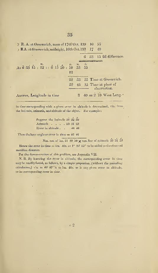
]) R. A. at Greenwich;, noon of 17th*^Oct. 139 10 55
}) R A. at Greenwich^ midnight;, 16th Oct.133 17 40
6 53 15 2d difference.
12
22 53 55 Time at Greenwich,
' 22 45 15 Time at place of ---- observation.
Answer^ Longitude in time 8 40 2 10 West Long- •
in time corresponding with a given error in altitude is determined, viz. from
the latitude, azimuth, and altitude of the object. For example :
o / //
Suppose the latitude 51 22 30
Azimuth . . . . 59 31 33
Error in altitude . . 46 46
Then the hour angle or error in time = 46 46 ■ ^ o / //
Nat. cos. of lat. 51 22 30 X azimuth 59 31 33
Hence the error in time = 5m. 48s. cr 1° 26' 55" to be added to the observed
meridian distance.
For the demonstration of this problem, see Appendix VII,
N. B. By knowing the error in altitude, the corresponding error in time
may be readily found, as follows, by a simple proportion, (without the preceding-
calculation,) viz. as 46' 46" is to 5m. 48s. so is any given error in altitude,
to its corresponding error in time.
36
EXAMPLE 2.
Of finding the Longitude by means of the observed
Declination of the Moon,
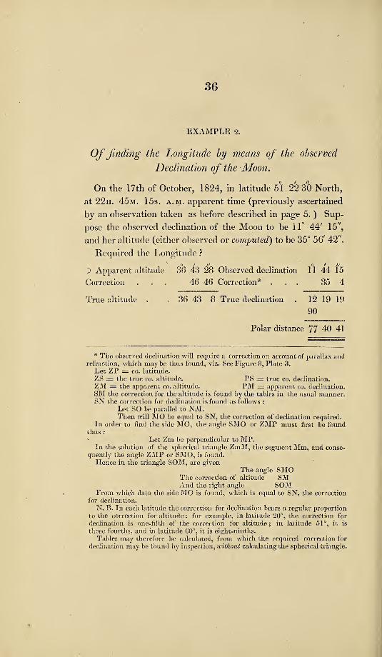
On the I7th of October, 1824, in latitude 51 22 30 North,
at 22h. 45m. 15s. a. m. apparent time (previously ascertained
by an observation taken as before described in page 5. ) Sup¬
pose the observed declination of the Moon to be 11° 44' 15'^,
and her altitude (either observed or computed) to be 35° 56' 42''.
Required the Longitude ?
1) Apparent altitude 36 43 28 Observed declination 11 44 15
Correction ... 46 46 Correction* ... 35 4
True altitude . . 36 43 8 True declination . 12 19 19
90
Polar distance 77 40 41
* The observed declination will require a correction on account of parallax and refraction, which maybe thus found, viz. See Figure 8, Plate 3.
Let ZP = CO. latitude. ZS = the true co. altitude. PS = true co. declination. ZM = the apparent co. altitude. PM = apparent co. declination. SM the correction for the altitude is found by the tables in the usual manner. SN the correction for declination is found as follows ;
Let SO be parallel to NM. Then will MO be equal to SN, the correction of declination required.
In order to find the side MO, the angle SMO or ZMP must first be found thus : ' Let Zm be perpendicular to MP.
In the solution of the spherical triangle ZmM, the segment Mm, and conse¬ quently the angle ZMP or SMO, is found.
Hence in the triangle SOM, are given The angle SMO
The correction of altitude SM And the right angle SOM
From which data the side MO is found, which is equal to SN, the correction for declination.
N. B. In each latitude the correction for declination bears a regular proportion to the correction for altitude: for example, in latitude 20°, the correction for declination is one-fifth of the correction for altitude; in latitude 51°, it is three fourths, and in latitude 60°, it is eight-ninths.
Tables may therefore be calculated, from which the required correction for declination may be found by inspection, without calculating the spherical triangle.

Latitude
Polar distance
37
. 51 2'2 30 Secant 0-204617
. 77 40 41 Co-secant 0*010121
2)165 46 39
Half sum . . 82 53 14 Co-sine 9*092801 Remainder . . 46 9 46 Sine 9*858121
2)19*165660
22 29 57 Sine 9*582830 8
Meridian distance . . 2 59 59
H. M. S.
Apparent time at place of observation . 22 45 15
O Right ascension corrected^ . . 13 28 56
Right ascension of the meridian . . 36 14 11 24
12 14 'll
D Meridian distance . . . 2 59 59
D Right ascension in time 9 14 12 60
4)554
D Right ascension in degrees . . 138° 33' 00^' I> R. A. at Greenwich, midn^ of 16th Oct. 132 17 40
6 15 20 1st difference.
D R. A. at Greenwich, at noon of 17th Oct. 139° 10' 55" R. A. at Greenwich, midn. of 16th Oct. 132 17 40
6 53 15 2d difference.
As 6° 53' 15" : 12h. : : 6° 15' 20" : IOh. 53m. 55s. 12
Time at Greenwich 22 53 55 ' Time at place 22 45 15
-Answer.
Longitude in time . • . 8 40 = 2° 10' W.
•• •Longitude.
* The Sun’s right ascension may be corrected by the longitude, by account i a few degrees of longitude will not aifect the result.
I

38
APPENDIX.—No. Ill, /
Ex tract from Captain Parry's Voyage of Discovery in
the year 1823. , ^
« The information obtained by Captain Lyon, on his late
journey with the Esquimaux, served very strongly to confirm
all that had before been understood from these people respect¬
ing the existence of the desired passage to the westward, in
this neighbourhood, though the impossibility of Captain Lyon’s
proceeding further in that direction, combined with our im¬
perfect knowledge of the language, still left us in some doubt
as to the exact position of the Strait in question: it was certain,
however, that it lay somewhere in that direction to which we
had been already so long and so anxiously looking, and that
its eastern entrance was still occupied by many miles of fixed
and*therefore impenetrable ice; but the very impediment that
had arrested Captain Lyon’s progress, as well as our daily ob¬
servations on the state of the ice near its outer margin, appeared
to offer a considerable hope that this obstacle must in the course
of nature very soon disappear, even by the gradual process of
dissolution, if it were not more speedily removed by one grand
and total disruption.
While, therefore. Captain Lyon was acquainting me with
his late proceedings, we shaped a course for Igloolik in order to
continue our look-out upon the ice, and made the tents very
accurately by the Compass, after a run of five leagues, when
the Hecla hauled in shore to pick up one of her men that had
been left there to procure game, and the Fury stood towards
the margin of the ice. Just before we reached off the floe.

39
the weather continuing extremely thick, with hard rain, I de¬
sired Mr. Crozier to set the extremes of the loom hanging over
Igloolik, which was then on our lee quarter. He did so, but
presently afterwards remarked that the compasses (both
Walker’s azimuth, and Alexander’s steering) indicated the
ship’s head to be S. W. which was about the middiepoint on
which, but a few minutes before, he had set the loom of the
land two or three points abaft the beam. Knowing, by the true
direction in which we were sailing, that the ship’s course by
the compass, if unaffected by any foreign local attraction,
should have been about East, which in fact the needles had
indicated previous to the change remarked by Mr. Crozier, I
tried what tapping with the hand (the usual expedient in
cases of mere sluggishness) would do, but without producing
any effect. Being now obliged to tack for the ice, we carefully
watched the compasses in standing off, and having sailed
about a quarter of a mile, observed them both return gradually
to their correct position. Being thus satisfied that some ex¬
traordinary local attraction was influencing the needles, we
again tacked to repeat the experiment, and with a nearly simi¬
lar result. The observations were then continued on one or
two successive tacks, the ship being steadily steered upon a
given point, by some object a-head; and an account of the
whole is subjoined in one connected view. The observations
were made between six and nine P. M. The wind being mo¬
derate at East (true,) the weather very rainy,r the soundings
hfty-two fathoms, afid the nearest land distant from six to eight
miles.
The space sailed over during the time the changes were
taking place, did not exceed a quarter of a mile.
Starboard
/

40
Starboard Tack, compasses first indicating the ship’s head
East, then changed to South West.
Larboard .N. W. b. N.S. W. i W.
Starboard.• East .... S. S. E.
Bore away to endeavour to cross our original track.
J Alexander’s compass N. W. b. N.. W. b. S. Larboard tacki „ ,,,
^ Walker’s . N. W.W. S. W.
Starboard, both compasses.East. S. W. ^ S.
Larboard ^ -Alexander’s... N. W. i N.S. W. b. W. | W.
I Walker’s.N. W.S. W. b. W. i W.
Starboard tack, both compasses.N. E. b. E. | E. .. E. J E.'
Alexander’s, a minute or two after, returned to N. E. b. E. | E.
and Walker’s to E. J N. Alexander’s compass was placed on
the binnacle, the other stood about five feet higher, in its usual
place.
In order to follow up the observations on this phenomenon
on some other day, I sent a boat to fix a flag upon the ice, by
way of marking the spot, but the margin was so broken up
that it was impracticable to land upon it; a light buoy was
therefore moored for the same purpose, though with little
chance of retaining its station, on account of the depth of water.
During the remainder of the night, when the wind and weather
obliged us to keep more to the northward, the compasses
were not thus influenced. *
“ The weather cleared up in the morning of the 2d.
We found that a strip of ice about half a mile in width had
been lately separated from the fixed ice, but this to our im¬
patience appeared like a drop of water in the ocean; con-
* The spots near which this local attraction was found, are designated on the
Chart by this mark, 0.

41
siderable streams and patches were also drifting along the
margin during the day, and we. were employed in breaking
through them in order to make fast to the floe, the weather
being unfavourable for keeping under way. In the evening
we secured the ships to the ice, being in twenty-three fathoms,
at the distance of two miles to the westward of Tern Island.
For several hours in the course of this day there was some¬
thing in the atmosphere which distorted objects into very
curious shapes. The principal feature in this phenomenon
was a constant waving tremulous motion near the horizon,
causing the whole body of ice to appear at times as if turning
round, and making one almost giddy to look steadfastly at it.
The distant land was sometimes flattened down so as to appear
like a single thick black line upon the horizon; then again
il would assume a shape of this kind—
when its real outline, when not thus distorted, was this,—
The tremulous appearance is, in a greater or less degree, a
very common phenomenon in the Polar Seas. Such, indeed,
is the frequent occurrence of extraordinary and variable
terrestrial refraction, and the consequent uncertainty with
respect to the dip of the horizon^ that observations made by
the horizon of the sea, even when wholly free from ice, cannot
be depended on within two or three minutes. There is, how-

42
ever, practically, little or nothing to regret on this account,
from the almost constant opportunities that occur in these
seas of resorting to the more accurate method of observation
by artificial horizons. The weather, which had for several
hours been rainy and thick, cleared up about noon on the
4th. In consequence of the wind shifting to the N. W. we
made sail Yrom the floe, in order to look for the buoy and to
continue our observations on the magnetic attraction in that
neighbourhood. After making several tacks as near the
place as the bearings of the land and the soundings could
direct us, but without discovering the buoy, we were obliged
for the present to give up the attempt; having to our great
satisfaction observed a floe, at least three miles in length and
two in breadth, just detached from the fixed ice, and rendering
it necessary for us to work out of its way lest it should force
us towards the shore: we only, therefore, waited to put down
some nets to ascertain the* nature of the bottom, and then
hauled round the floe. A quantity of shells, among which
were a few of the new species of Anomia discovered on the
last voyage, with some shrimps and echini, were all that
we could thus fish up. Having cleared the end of the floe,
which drifted rapidly away, and, as usual here, never made its
appearance afterwards, we made the ships fast to the fixed ice
P. M. having by the late disruption made considerable pro¬
gress in the direction of the Strait.”
Page 317.—“ The wind gradually falling, was succeeded by
a light easterly breeze, with which, at daylight on the 26th,
we steered under all possible sail up the Strait. The course
being shaped, and no ice in our way, I then went to bed; but
was immediately after informed by Mr. Crozier that the
compasses had shifted from N ^ E., (which was the course
I left them indicating) to E ^ N., being a change of seven
points in less than ten minutes. After running half a mile in
a true W. by N. direction, the needles began to return to their

43
true position; in half a mile farther they had resumed their
proper direction, and agreed exactly at North. Having sent a
boat to the Hecla immediately on our noticing the first alte¬
ration, I found from Captain Lyon that a similar phenomenon
was observed to take place on board that ship, which was
following in our wake. The breeze slowly increasing from
the eastward, and the ^veather happily remaining unusually
clear for that direction of the wind, we soon arrived ofP the
narrow part of the Strait; immediately on opening which, we
met a tide or current running above two knots to the east¬
ward, with numerous eddies and ripplings. By keeping on
the South, or continental shore, and passing along by Cape
N. E. within two or three hundred yards of the rocks, we
succeeded, with the assistance of the boats a-head, in getting
through the channel soon after eleven o’clock.”
EMract from Captain Lyon's Voyage of Discovery,
Latitude 61° 13'—Longitude 63° 54'.
The deviation of our compasses was here very great and
irregular, although less so with our head northward, than
otherwise : even Gilbert’s excellent azimuth compass required
constant tapping, although under the influence of Professor
Barlow’s plate, which had hitherto corrected it with the great¬
est accuracy.”—Page 30.
The stillness of this day was highly favourable for ob¬
taining observations for the dip of the needle ; but the floe
to which we were fast was not of sufficient extent to admit
of our getting so far from the ship as to be free from her at¬
traction: I was now the more desirous of obtaining these
observations, on account of the fast increasing sluggishness of
the compasses,—^for that of Gilbert’s, which had hitherto been
fully corrected for the local attraction of the ship by Barlow’s

44
plate, now began to shew nearly as much deviation when our
head was to the eastward, as any of the other compasses.”—
Page 44.
Our compasses had now become quite useless, with our
head southerly; and that in particular to which the plate
v/as fitted, so powerless, that its North point stood wherever
it was placed by the finger; but with our head northerly,
they all traversed again. This, however, benefited us but
little; for, as our route lay to the South West, we were with¬
out other guidance than Celestial bearings, which could not
always be obtained.”—Page 53.
In the forenoon watch, our larboard compass, which, with
two others, had shewn our head N. b. W. which (with three
points and a half westerly variation) agreed with the Sun’s
bearing, in giving a N. W. i W. course, suddenly pointed
E. N. E., and no tapping or motion would keep it in any
other point for two or three minutes; after which, it as sud¬
denly recovered its agreement with the others, and continued
quite correct. We now, from repeated observations, disco¬
vered that when our head was nearly North by compass, the
deviation was three points and a half West; but when be¬
tween North and West, it amounted to eight poinfs; while with
the head to the Southward, the compasses would generally
rest wherever they were directed by the finger; and some¬
times each persisted in maintaining a direction of its own.
Barlow’s plate now became useless, and its want of effect
was decided by finding Gilbert’s compass, while under its
immediate influence, the dullest in the ship.”
Ellis, in his account of the Expedition of the Dobbs and
California, in 1746, says:— "
I cannot help taking notice in this place (while off Ches¬
terfield Inlet), while amongst these islands, and in sailing
through the ice, the needles of our compasses lost their mag-

45 I
netical qualities : one seeming to act from this direction, and
another under that; and yet they were not for any consider¬
able time constant to any. We laboured to remedy this evil,
by touching them with an artificial magnet, but to very little
purpose; for if they recovered their powers by this means,
they presently lost them again.”—Ellis’s Account^ page 220,
in the year 1748.
Although the fogs in the Polar regions are so frequently
mentioned in the course of the recent narrations which have
been published, I believe they are generally understood as
resembling our English fogs, which is not in fact the case.
In the Northern seas, these vapours rarely rise to above a
hundred feet from the sea, and a sky of most provoking
brilliancy is frequently seen overhead.”—Lyon’s Voyage,
page 43.

46
APPENDIX.—No. IV.
E.vtract from Captain Franklin's Journey to the Polar
1819.
August 12th.—Azimuths were obtained this evening that
gave the variation 58° 45' 0", which is greater than is laid
down in the Chart, or than the officers of the Hudson’s Bay
ships have been accustomed to allow. Latitude 57° North.”
—Page 26.
August i9th.—Nothing worthy of remark occurred, ex¬
cept the rapid decrease in the variation of * the magnetic
needle.
N. B. At York factory the variation is only 6° 00' 21"
East.”—Page 32.
. September 25th.—About half a mile from the bend or
knee of the lake^ there is a small rocky islet, composed of
magnetic iron ore, which affects the magnetic needle at a con¬
siderable distance. Having received previous information re¬
specting this circumstance, we watched our compasses carefully,
and perceived that they were affected at the distance of three
hundred yards, both on the approach to and departure from the
rock; on decreasing the distance, they became more and more
unsteady; and on landing they were rendered quite useless,
and it was evident that the general magnetic influence was
totally overpowered by the local attraction of the ore. "When
Eater’s compass was held near to the ground on the North
West side of the island, the needle dipped so much that the
card could not be made to traverse by any adjustment of the
- hand; but on moving the same compass about thirty yards to
the West part of the islet, the needle became horizontal, tra¬
versed freely, and pointed to the magnetic North. The dip-

47
ping needle being landed on the South West point of the
islet, was adjusted as nearly as possible on the magnetic me¬
ridian, by the Sun’s bearings, and found to vibrate freely:
when the face of the instrument was directed to the East or
West, the mean dip it gave was 80^ 37' 50''; when the instru¬
ment was removed from the North West to the South East
point, about twenty yards distant, and placed on the meridian,
the needle ceased to traverse, but remained steady at an angle
of 60°; on changing the face of the instrument so as to give
it a South East and North West direction, it hung vertically.
The position of the slaty strata of the magnetic ore is also
vertical,—their direction is extremely irregular, being much
contorted.”—^Page 56.
The observations of this evening seem to corroborate the
remark which I had previously made, that the direction in
which the needle moves seems to depend upon the position in
which the streams of the Aurora Borealis are placed, and the
quantity of its effect to its proximity to or distance from the
earth. When the extremities of the arches lay near the bearings
of 324® and 54°, the needle moved eastward; and when near
the bearing, 324® and 144®, or 279“ or 99®, the motion of the
needle was westward : both of these facts were shewn to-night.
At the first display, when the extremities of the arches pointed
near 234® and 54, and the interior motion followed the same
direction, the needle moved eastward as far as 345®, but after
midnight, coruscations ceased to appear in that direction, and
at 12'^ lO''’, were presented in three arches traversing the
zenith, whose extremities pointed 12.1® and 302®; the needle
then receded towards the West, and rested at 349® 30', having
varied its position 5° 40' in the course of twenty minutes.”—
Page 560.
I apprehend much of the irregularity in the result of the
observations for the variation of the compass along the Copper
Mine River is to be attributed to local causes of attraction.

48
and particularly to the existence of iron ore among the rocks,
which is very general: a greater intermixture of iron ore was
perceived in the rocks on the sea coast, than on the banks of
the Copper Mine River.”—Page 635.
The seat of the phenomenon of the Aurora Borealis lies
between the latitudes 64® and 65® North, or about the position
of Fort Enterprize, because the coruscations were as often ^een
there in^ the southern as in the northern parts of the sky.”—
Page 553.
The Island of Canna, on the western coast of Scotland,
affords a remarkable instance of the effects on the magnetic
needle from the local attraction of mountains (charged with
iron ore.)—*S'ce Murray’s Tour to the Hebrides.


n 1.


APPENDIX.—No. VI.
The following Problem^ for computing the Error in
Time corresponding to a given Error in Altitude,
is selectedfrom Gregory s Trigonometry.—See Figure
VL, Plate TIL
Let N M be a portion of the Equator, P the elevated
Pole, S o a portion of the parallel of decimation in which the
heavenly body is on the day of observation; and let o be the
real, and r the apparent place of the body, or o r the error in
altitude ; draw S r parallel to the horizon; from Z the Zenith,
draw Z S Z o; and from P the Pole, the meridians P S N,
P o M, to pass through S and o, and cut the Equator N M ;
then S and o will be the apparent and real places of the
body on the parallel of declination; and the arc S o, in that
circle, or N M on the Equator, will measure the angle S P o,
the corresponding error in time.
The triangle S r o, being of course exceedingly small, may
be regarded as a rectilinear triangle, right angled at r :
Hence r o : o S :: Sine of r S o : radius
and so: N M :: Cos. of M o : radius.
Consequently, by multiplying the corresponding terms,
we have, ro xSoiSoX NM:: Sine of r S O x Cos.
M O : radius, or rejecting S o from the first and second terms,
r o : N M : : Sine of r S o, Cos. M O : radius.
Whence N M=r o ~ cos. M o.
But ZoP=rso, ros being the complement of each,
and Sine Z o P (=Sine r S o) : P Z : : Sine o Z P : Sine P o.

50
Consequently r S o. Sine P o—Sine r S O5 Cos. M o—Sine P Z,
Sine r Z P. Therefore by substituting for the denominator
in equation 1, its equivalent in the last, we have
N _ or_ Sine PZ Sine o ZP oZP or NM=error in time.
, . . or, (error in altitude.)
or the error in time=co riL lat. Sine of azimuth.-

51
APPENDIX.—No. VII.
A Comparative Statement of the Change of the Moon's
Right Ascension in a given time^ with the change of
her Angular Distance from the Sun or a Star during
the same time. For the Year 1824.
. .
J Date. .
)ifference of Moon’s Right A-scension be¬ tween Noon and Midnight.
|]
Star’s j name. ^
Difference of Moon’s Angu¬ lar Distance between Noon and Midnight.
Difference between Right Ascension and Angular Distance during the same time, or during 12 hours.
March 9 o / // 7 41 35 Sun
O
6 31 44 o
1 /
D 5l' R. A.
Arietis 7 00 46 0 40^ 49 R. A.
— Regulus 7 1 37 0 39 50 R. A.
20 6 55 8 Sun 5 47 15 1 7 53 R. A.
Formal 5 41 45 1 13 23 R. A.
26 5 35 8 Sun 5 24 16 0 10 52 R. A.
A TltflPPSl 5 56 32 0 20 24Aii0' Dis.
Sept. 26 7 14 27
xXJlX LCil CO
Sun 6 17 6 0 56 19 R. A.
Aquila 5 57 14 1 17 11 R. A.
Oct. IS 1—•
Sun 5 9 9 1 7 38 R. A.
Regulus 6 38 47 0 39 0 R. A.
Nov. » 6 5 54 Sun 5 34 26 0 31 28 R. A.
LONDON:
PRINTED BY S. AND S. BENTLEY, DORSET-STREET.


