the dynamic vpn controller · the dynamic vpn controller ... (vpns), and has demonstrated the dvc...
TRANSCRIPT

The Dynamic VPN Controller Secure information sharing in a coalition environment
Dr. S. Zeber, J. Spagnolo and D. Cayer
Defence R&D Canada √ Ottawa TECHNICAL MEMORANDUM
DRDC Ottawa TM 2005-025 March 2005

Report Documentation Page Form ApprovedOMB No. 0704-0188
Public reporting burden for the collection of information is estimated to average 1 hour per response, including the time for reviewing instructions, searching existing data sources, gathering andmaintaining the data needed, and completing and reviewing the collection of information. Send comments regarding this burden estimate or any other aspect of this collection of information,including suggestions for reducing this burden, to Washington Headquarters Services, Directorate for Information Operations and Reports, 1215 Jefferson Davis Highway, Suite 1204, ArlingtonVA 22202-4302. Respondents should be aware that notwithstanding any other provision of law, no person shall be subject to a penalty for failing to comply with a collection of information if itdoes not display a currently valid OMB control number.
1. REPORT DATE MAR 2005 2. REPORT TYPE
3. DATES COVERED -
4. TITLE AND SUBTITLE The Dynamic VPN Controller (U)
5a. CONTRACT NUMBER
5b. GRANT NUMBER
5c. PROGRAM ELEMENT NUMBER
6. AUTHOR(S) 5d. PROJECT NUMBER
5e. TASK NUMBER
5f. WORK UNIT NUMBER
7. PERFORMING ORGANIZATION NAME(S) AND ADDRESS(ES) Defence R&D Canada -Ottawa,3701 Carling Ave,OttawaOntario,CA,K1A 0Z4
8. PERFORMING ORGANIZATIONREPORT NUMBER
9. SPONSORING/MONITORING AGENCY NAME(S) AND ADDRESS(ES) 10. SPONSOR/MONITOR’S ACRONYM(S)
11. SPONSOR/MONITOR’S REPORT NUMBER(S)
12. DISTRIBUTION/AVAILABILITY STATEMENT Approved for public release; distribution unlimited
13. SUPPLEMENTARY NOTES The original document contains color images.
14. ABSTRACT Defence R&D Canada (DRDC) developed the dynamic virtual private network controller (DVC) prototypeas a concept demonstrator for the rapid deployment and self-configuration of one or more dynamiccoalition virtual private networks (VPNs), and has demonstrated the DVC prototype in both local andinternational environments. The DRDC DVC prototype is a network boundary protection device thatprovides access to its protected network infrastructure in a controlled fashion to one or more approvedcoalition partners without requiring any knowledge of a remote partner’s protected networkinfrastructure. This report describes the design and operation of the DVC prototype, its current state ofdevelopment, and the ongoing work to evolve the DVC capabilities for policy-based management anddynamic configuration. The DVC prototype provides a flexible, interoperable, application-independentsolution for secure information exchange that does not require any knowledge of a remote partner’snetwork infrastructure. The development of the DVC capability supports the strategic C4ISR goal of anenhanced capability for secure information interchange for military operations.
15. SUBJECT TERMS
16. SECURITY CLASSIFICATION OF: 17. LIMITATION OF ABSTRACT
18. NUMBEROF PAGES
146
19a. NAME OFRESPONSIBLE PERSON
a. REPORT unclassified
b. ABSTRACT unclassified
c. THIS PAGE unclassified
Standard Form 298 (Rev. 8-98) Prescribed by ANSI Std Z39-18


The Dynamic VPN Controller Secure information sharing in a coalition environment
Dr. S. Zeber DRDC Ottawa
J. Spagnolo NRNS Incorporated
D. Cayer NRNS Incorporated
Defence R&D Canada – Ottawa Technical Memorandum DRDC Ottawa TM 2005-025 March 2005

© Her Majesty the Queen as represented by the Minister of National Defence, 2005
© Sa majesté la reine, représentée par le ministre de la Défense nationale, 2005

DRDC Ottawa TM 2005-025 i
Abstract
Defence R&D Canada (DRDC) developed the dynamic virtual private network controller (DVC) prototype as a concept demonstrator for the rapid deployment and self-configuration of one or more dynamic coalition virtual private networks (VPNs), and has demonstrated the DVC prototype in both local and international environments. The DRDC DVC prototype is a network boundary protection device that provides access to its protected network infrastructure in a controlled fashion to one or more approved coalition partners without requiring any knowledge of a remote partner’s protected network infrastructure. This report describes the design and operation of the DVC prototype, its current state of development, and the ongoing work to evolve the DVC capabilities for policy-based management and dynamic configuration. The DVC prototype provides a flexible, interoperable, application-independent solution for secure information exchange that does not require any knowledge of a remote partner’s network infrastructure. The development of the DVC capability supports the strategic Command, Control, Communication, Computers, Intelligence, Surveillance and Reconnaissance (C4ISR) goal of an enhanced capability for secure information interchange for military operations.
Résumé
L’agence de Recherche et développement pour la défense Canada (RDDC) a développé le prototype du contrôleur de réseau virtuel privé dynamique (CVD) comme démonstrateur de concept pour le déploiement et la configuration rapide d'un ou plusieurs réseaux privés virtuels dynamiques en coalition. RDDC a démontré ce prototype dans des environnements locaux et internationaux. Le prototype de RDDC est un dispositif de protection de frontière de réseau qui permet d'accéder à l’infrastructure protégée d’un réseau de façon contrôlée à un ou plusieurs membres associés en coalition sans exiger aucune connaissance de l'infrastructure protégée du réseau d'un autre associé, et ce même à distance. Ce rapport décrit la conception et l'opération du prototype CVD, de son état actuel en développement, et du travail continu pour développer les capabilités du CVD pour la gestion des polices et la configuration dynamique. Le prototype CVD fournit une solution flexible, interopérable et indépendante des applications pour l'échange d'information sécurisée et qui n'exige aucune connaissance de l'infrastructure du réseau d'un membre associé à distance. Le développement des capabilités du CVD soutient le but stratégique du commandement, contrôle, communication, informatique, renseignement, surveillance et reconnaissance (C4ISR) d’augmenter la capabilité pour l'échange sécurisé de l'information pour les opérations militaires.

ii DRDC Ottawa TM 2005-025
This page intentionally left blank.

DRDC Ottawa TM 2005-025 iii
Executive summary
Defence R&D Canada (DRDC) developed the concept of the dynamic virtual private network controller (DVC) as a possible approach for the rapid deployment and self-configuration of one or more dynamic coalition VPNs. The DVC was conceived as a network boundary protection device that provides access to its protected network infrastructure in a controlled fashion to one or more approved coalition partners without requiring any knowledge of a remote partner’s protected network infrastructure. A partner is simply identified by its network identity (IP address) and its secure identity (a name encoded in its trusted certificate).
The DRDC DVC prototype, which connects a coalition member’s protected network to an unprotected coalition wide area network, provides application-independent network layer protection for all traffic through the device using IPsec encryption. The DVC prototype uses Secure Socket Layer (SSL) sessions authenticated with X.509 certificates as secure out-of-band control channels to exchange policy information and establish a VPN connection with a remote partner, as well as to report on the status of the coalition VPN. The DVC prototype can establish fully meshed point-to-point VPN connections among a set of coalition partner sites, which are assumed to operate at a common security level. Each point-to-point VPN connection encrypts the traffic between two coalition sites. Traffic sent over a VPN connection between two coalition sites is never routed through a third coalition site.
The DVC-defined and maintained policies are best described as “inter-domain” security policies. The inter-domain security policies identify the local networks that require access to a remote partner’s services as well as which local services within the local domain can be “exported” to a remote partner. The DVC expresses its inter-domain security policies using the eXtensible Markup Language (XML).
The information that typically is configured statically within an IPsec compliant device is instead derived when the DVC merges locally configured security policies with the security policies proposed by a remote partner. If approved by both partners, the DVC uses the merged security policies to create the configuration information required by the co-located policy enforcement point (PEP), which not only enforces the negotiated policies but also facilitates the use of the VPN by configuring both the local routing domain and naming services. By performing a significant amount of self-configuration, the DVC reduces the management overhead and labour-intensive aspects of maintaining coherent VPN infrastructures.
The DVC prototype includes both a Policy Editor and a Management Console. The DVC Policy Editor is a Java based application that facilitates the compilation of security policies that conform to a defined XML schema. The DVC operator interface is a web-based application that presents a graphical view of the entire coalition membership. The DVC operator can establish and dismantle VPNs as well as view the health of the entire VPN from both the local perspective as well as from the perspective of all other coalition members.

iv DRDC Ottawa TM 2005-025
The DVC prototype, which supports both IPv4 and IPv6 protocols, has been demonstrated locally over the DREnet, in a six-node coalition scenario, and internationally, over the Internet, with nodes at DRDC, University College London (UCL) and the University of Murcia (UMU) in Spain. UCL has also demonstrated the DVC prototype over the 6NET.
Zeber, S., Spagnolo, J., Cayer, D. 2005. The Dynamic VPN Controller. DRDC Ottawa TM 2005-025. Defence R&D Canada - Ottawa.
DRDC Ottawa TM 2005-025 v
Sommaire
L’agence de Recherche et développement pour la défense Canada (RDDC) a développé le prototype du contrôleur de réseau virtuel privé dynamique (CVD) comme démonstrateur de concept pour le déploiement et la configuration rapide d'un ou plusieurs réseaux privés virtuels dynamiques en coalition. Le prototype de RDDC est un dispositif de protection de frontière de réseau qui permet d'accéder à l’infrastructure protégée d’un réseau de façon contrôlée à un ou plusieurs membres associés en coalition sans exiger aucune connaissance de l'infrastructure protégée du réseau d'un autre associé, et ce même à distance. Le membre partenaire est simplement identifié par son identité en réseau (l’adresse IP) et son identité sécurisé (un nom encodé dans son certificat de confiance).
Le prototype CVD de RDDC, qui relie le réseau protégé d'un membre de la coalition à un réseau étendu de coalition non protégé, fournit une protection à application indépendante de couche réseau pour tout le trafic à travers le dispositif en utilisant le chiffrage d'IPsec. Le prototype CVD utilise les sessions authentifiées avec certificats X.509 en protocole SSL en tant que canaux de commande hors bande afin d’échanger les politiques d’information et pour l’établissement d’un raccordement a réseau privé virtuel (RPV) avec un partenaire à distance, aussi bien que pour rendre compte du statut du RPV de la coalition.
Le prototype CVD peut établir la connexion entièrement engrenée pour diriger les raccordements de RPV parmi un ensemble d'endroits des associés en coalition, assumant qu’ils fonctionnent à un niveau commun de sécurité. Chaque point de raccordement en RPV chiffre le trafic entre les deux emplacements de coalition. Le trafic envoyé au-dessus d'un raccordement de RPV entre deux emplacements de coalition n'est jamais conduit par un troisième emplacement de coalition. Les politiques définies et maintenues du CVD sont mieux décrites en tant que « politiques de sécurité inter-domaines ». Les politiques de sécurité inter-domaines identifient les réseaux locaux qui exigent l'accès aux services d'un associé a distance aussi bien que les services locaux dans le domaine local qui peuvent "être exportés" vers un associé à distance.
Le CVD exprime ses politiques de sécurité inter-domaines en utilisant le langage de balisage extensible (XML). L'information qui typiquement est configurée statiquement dans un dispositif conforme d'IPsec est à la place dérivée quand le CVD fusionne les politiques localement configurées de sécurité avec les politiques de sécurité proposées par un associé à distance. Si approuvé par les deux associés, le CVD emploie les politiques fusionnées de sécurité pour créer l'information de configuration exigée par le point d’application des politiques co-localisées, qui imposera non seulement les politiques négociées mais facilitera également l'utilisation du RPV en configurant les services du domaine local de distribution et les services d’attribution de noms.

vi DRDC Ottawa TM 2005-025
En exécutant une quantité significante d’autoconfiguration, le CVD réduit les frais généraux de gestion et les aspects à main d'oeuvre intense pour maintenir les infrastructures logiques du RPV. Le prototype CVD inclut un rédacteur de politique et une console de gestion. Le rédacteur de politique du CVD est une application basée sur Java qui facilite la compilation des politiques de sécurité qui se conforment à un schéma défini par XML. L'interface d'opérateur du CVD est une application web qui présente une vue graphique de tous les membres de la coalition. L'opérateur du CVD peut établir et démanteler les liens RPV, aussi bien que surveiller le statut complet du RPV, et ce autant bien en perspective locale qu’en perspective de tout autres membres de la coalition.
Le prototype CVD, qui soutient les protocoles IPv4 et IPv6, a été démontré localement à travers du réseau DREnet, dans un scénario de coalition de six nœuds, et internationalement, au-dessus de l'Internet, avec des noeuds à RDDC, à l’université de Londres (UCL) et à l'université de Murcia (UMU) en Espagne. UCL a également démontré le prototype de CVD au-dessus du NET.
Zeber, S., Spagnolo, J., Cayer, D. 2005. The Dynamic VPN Controller. DRDC Ottawa TM 2005-025. R & D pour la défense Canada - Ottawa.

DRDC Ottawa TM 2005-025 vii
Table of contents
Abstract........................................................................................................................................ i
Executive summary ................................................................................................................... iii
Sommaire.................................................................................................................................... v
Table of contents ...................................................................................................................... vii
List of figures ........................................................................................................................... xii
List of tables ............................................................................................................................ xiv
Acknowledgements .................................................................................................................. xv
1. Introduction ................................................................................................................... 1 1.1 Background ...................................................................................................... 1 1.2 About this report............................................................................................... 1
2. Coalition Concepts ........................................................................................................ 3 2.1 Definition of a Coalition................................................................................... 3 2.2 Military Coalitions............................................................................................ 3 2.3 Dynamic Coalitions .......................................................................................... 4 2.4 Other Coalition Examples ................................................................................ 4 2.5 Information Sharing for Dynamic Coalitions................................................... 5 2.6 The VPN Solution for Dynamic Coalitions...................................................... 5
2.6.1 Scenario Description ........................................................................... 5 2.6.2 VPN Requirements.............................................................................. 7
3. The DVC Design and Operation ................................................................................... 9 3.1 Motivation ........................................................................................................ 9 3.2 Design Principles.............................................................................................. 9 3.3 System Architecture ....................................................................................... 12 3.4 Principles of Operation................................................................................... 14
3.4.1 Overview ........................................................................................... 14

viii DRDC Ottawa TM 2005-025
3.4.2 Establishing a VPN ........................................................................... 15 3.4.3 Authentication ................................................................................... 18
3.4.3.1 DVC Project CA ............................................................ 18 3.4.3.2 Local DVC CA .............................................................. 19
3.4.4 Health Monitoring and Status Reporting........................................... 20 3.4.5 Dismantling a VPN ........................................................................... 20
3.5 Evolution of the DVC..................................................................................... 22
4. The DVC Implementation ........................................................................................... 24 4.1 Overview ........................................................................................................ 24 4.2 The DVC Process ........................................................................................... 24 4.3 DVC to DVC Communications...................................................................... 25
4.3.1 DVC-to-DVC Message Formats ....................................................... 26 4.3.1.1 Propose Policy ............................................................... 28 4.3.1.2 Accept Propose Policy ................................................... 29 4.3.1.3 Accept ............................................................................ 30 4.3.1.4 Deny............................................................................... 31 4.3.1.5 Delete ............................................................................. 32 4.3.1.6 Status.............................................................................. 33 4.3.1.7 Error ............................................................................... 34 4.3.1.8 Close .............................................................................. 35 4.3.1.9 Pingreply........................................................................ 36 4.3.1.10 Localerror....................................................................... 36
4.4 DVC Management Communication ............................................................... 37 4.5 Configuring the DVC ..................................................................................... 37
4.5.1 DVC Configuration ........................................................................... 37 4.5.2 Policy Configuration ......................................................................... 38
4.6 DVC Subsystem Management ....................................................................... 38 4.6.1 The Firewall Subsystem .................................................................... 39
4.6.1.1 Description and Data Structure...................................... 39 4.6.1.2 Initial Configuration ...................................................... 40 4.6.1.3 Run-Time Configuration................................................ 40
4.6.2 The Routing Subsystem..................................................................... 41

DRDC Ottawa TM 2005-025 ix
4.6.2.1 Description and Data Structure...................................... 41 4.6.2.2 Initial Configuration ...................................................... 41 4.6.2.3 Run-Time Configuration................................................ 42
4.6.3 The DNS Subsystem ......................................................................... 42 4.6.3.1 Description and Data Structure...................................... 42 4.6.3.2 Initial Configuration ...................................................... 43 4.6.3.3 Run-Time Configuration................................................ 43
4.6.4 The IPsec Subsystem......................................................................... 44 4.6.4.1 Description and Data Structure...................................... 44 4.6.4.2 Initial Configuration ...................................................... 46 4.6.4.3 Run-Time Configuration................................................ 46
4.7 Network Communications.............................................................................. 46 4.7.1 External Communication Requirements............................................ 46 4.7.2 Internet Protocol Support .................................................................. 47
5. The DVC Management Console.................................................................................. 49 5.1 Operator Interface........................................................................................... 49 5.2 DVC Management Console Commands......................................................... 51
5.2.1 Retrieve ............................................................................................. 52 5.2.2 Connect.............................................................................................. 53 5.2.3 SConnect ........................................................................................... 54 5.2.4 Delete................................................................................................. 54 5.2.5 SDelete .............................................................................................. 55 5.2.6 Enable................................................................................................ 55 5.2.7 SEnable.............................................................................................. 55 5.2.8 DATA................................................................................................ 56
6. The DVC Policy Editor ............................................................................................... 57 6.1 Overview ........................................................................................................ 57 6.2 DVC Policy Files............................................................................................ 57
6.2.1 DVC Policy Specification File .......................................................... 58 6.2.1.1 Enforcement Points........................................................ 60 6.2.1.2 Local Networks.............................................................. 61 6.2.1.3 Services.......................................................................... 62

x DRDC Ottawa TM 2005-025
6.2.1.4 Local Domains............................................................... 63 6.2.1.5 Local Servers ................................................................. 64 6.2.1.6 Local Services................................................................ 65 6.2.1.7 Coalition and Site Definition ......................................... 66 6.2.1.8 Remote Policy Definition .............................................. 68 6.2.1.9 Local Policy Definition.................................................. 69
6.2.2 DVC Policy Configuration File......................................................... 70 6.2.2.1 Coalition and Site Definition ......................................... 71 6.2.2.2 Remote Policy Definition .............................................. 72 6.2.2.3 Local Policy Definition.................................................. 73
7. Observations and Analysis .......................................................................................... 75 7.1 DRDC Demonstration .................................................................................... 75 7.2 International Demonstrations ......................................................................... 77 7.3 Related Projects .............................................................................................. 77
7.3.1 INSC.................................................................................................. 77 7.3.2 University of Murcia ......................................................................... 78
7.3.2.1 UMU-PKIv6 .................................................................. 78 7.3.2.2 UMU-PBNM ................................................................. 78
7.3.3 6NET Experiments ............................................................................ 79
8. Conclusions ................................................................................................................. 80 8.1 Summary ........................................................................................................ 80 8.2 Further Research............................................................................................. 80
9. References ................................................................................................................... 82
Annex A: DVC Software.......................................................................................................... 83
Annex B: DVC Configuration Files ......................................................................................... 85 The DVC Configuration File....................................................................................... 85 The DVC Policy Configuration File............................................................................ 87 The DVC Security Class File ...................................................................................... 87
Annex C: DVC System Installation.......................................................................................... 89

DRDC Ottawa TM 2005-025 xi
Annex D: DVC System Configuration ..................................................................................... 92
Annex E: DVC Commands XML Schema............................................................................... 97
Annex F: Example DVC Policy Specification File ................................................................ 103
Annex G: DVC Policy Specification File Schema ................................................................. 107
Annex H: Example DVC Policy Configuration File .............................................................. 111
Annex I: DVC Policy Configuration File Schema ................................................................. 115
List of symbols and abbreviations .......................................................................................... 119
Glossary.................................................................................................................................. 121

xii DRDC Ottawa TM 2005-025
List of figures
Figure 1. Dynamic Coalition Operational Scenario ................................................................... 6
Figure 2. DVC System Architecture......................................................................................... 13
Figure 3. Typical DVC Deployment for a two member coalition ............................................ 15
Figure 4. Establishing a VPN ................................................................................................... 17
Figure 5. DVC Certificate Usage ............................................................................................. 19
Figure 6. Dismantling a VPN ................................................................................................... 21
Figure 7. DVCCmd .................................................................................................................. 26
Figure 8. SSLCmd .................................................................................................................... 27
Figure 9. PIPECmd................................................................................................................... 28
Figure 10. Propose.................................................................................................................... 29
Figure 11. Apropose ................................................................................................................. 30
Figure 12. Accept ..................................................................................................................... 31
Figure 13. Deny ........................................................................................................................ 32
Figure 14. Delete ...................................................................................................................... 33
Figure 15. Status ....................................................................................................................... 34
Figure 16. Error ........................................................................................................................ 35
Figure 17. Close........................................................................................................................ 36
Figure 18. Pingreply ................................................................................................................. 36
Figure 19. Localerror................................................................................................................ 37
Figure 20. DVC Management Console Coalition-level View.................................................. 50
Figure 21. DVC Management Console Site-level View .......................................................... 51
Figure 22. DVC Policy Editor Object File ............................................................................... 59
Figure 23. Enforcement Points ................................................................................................. 61

DRDC Ottawa TM 2005-025 xiii
Figure 24. Local Networks ....................................................................................................... 62
Figure 25. Services ................................................................................................................... 63
Figure 26. Local Domains ........................................................................................................ 64
Figure 27. Local Servers........................................................................................................... 65
Figure 28. Permitted Traffic ..................................................................................................... 66
Figure 29. Coalition Specification............................................................................................ 67
Figure 30. Site Specification .................................................................................................... 68
Figure 31. Remote Policy Specification ................................................................................... 69
Figure 32. Local Policy Specification ...................................................................................... 70
Figure 33. DVC Policy Configuration File............................................................................... 71
Figure 34. DVC Policy - Coalition........................................................................................... 71
Figure 35. DVC Policy - Site.................................................................................................... 72
Figure 36. DVC Policy - Remote Policy .................................................................................. 72
Figure 37. DVC Policy - Local Policy ..................................................................................... 74
Figure 38. DVC Demonstration Configuration ........................................................................ 76

xiv DRDC Ottawa TM 2005-025
List of tables
Table 1. DVC Compliance with Dynamic VPN Requirements................................................ 10
Table 2. Steps to create a VPN ................................................................................................. 17
Table 3. Steps to dismantle a VPN ........................................................................................... 21
Table 4. DVC Communication................................................................................................. 25
Table 5. Remote DVC Messages.............................................................................................. 27
Table 6. Local DVC Messages ................................................................................................. 28
Table 7. Firewall Subsystem Data Structure ............................................................................ 39
Table 8. Routing Subsystem Data Structure............................................................................. 41
Table 9. DNS Subsystem Data Structure.................................................................................. 43
Table 10. IPsec Subsystem Data Structure ............................................................................... 44
Table 11. Encryption Algorithms ............................................................................................. 45
Table 12. Authentication Algorithms ....................................................................................... 45
Table 13. External Communication Requirements................................................................... 46
Table 14. IP Version Matrix ..................................................................................................... 47
Table 15. DVC GUI Commands .............................................................................................. 52
Table 16. DVC Retrieve Commands ........................................................................................ 53
Table 17. DVC Objects ............................................................................................................ 60
Table 18. DVC Demonstration Policies ................................................................................... 75
Table 19. DVC Demonstration Scenarios ................................................................................ 76
Table 20. Software Components .............................................................................................. 83

DRDC Ottawa TM 2005-025 xv
Acknowledgements
The authors are greatly indebted to Mr. Vincent Taylor, recently retired from DRDC Ottawa, who inspired and initiated this work and who provide valuable guidance and comments as this work was carried out.
The authors would also like to thank Mr. Tim Symchych of CRC for reviewing the manuscript and making very helpful editorial suggestions.

xvi DRDC Ottawa TM 2005-025
This page intentionally left blank.

DRDC Ottawa TM 2005-025 1
1. Introduction
1.1 Background
New challenging concepts and ideas of military operations like NATO Network Enabled Capabilities (NNEC) and Network Centric Warfare (NCW) dramatically change the requirements on the capabilities of the communications and information solutions for coalition operations. Emphasis is put on specific features of communications networks such as: mobility, deployability, security, self-configuration, survivability, and so forth. Demand for quick implementation of disruptive innovations and emerging communications technologies in military systems calls for adaptation of mature and cheap solutions as developed for the commercial market. This requires comprehensive evaluation of the capabilities of recent and anticipated technological advances in communications to meet the military users’ requirements.
Many ongoing efforts are made throughout NATO in the field of improving existing communications infrastructure. Important national and multinational research and standardization initiatives will be finalized in the next two years, including: TACOMS Post 2000, Interoperable Network for Secure Communications (INSC), and the Joint Tactical Radio System (JTRS). In addition, several new national procurement programmes have been started (Attila (FR), Falcon (UK), TITAAN (NL), Win-T (US) and others).
The modern warfare environment depends increasingly on the deployment of multinational coalitions and joint operations that require the coordination of the land, sea and air forces of the coalition members. Furthermore, the coalition membership is often dynamic, changing over time. Such an environment requires quickly deployable network communications, interoperability, and the ability to exchange information securely and in a timely manner. It also requires the ability to protect information and network assets from unauthorized access by enforcing compartmentalization and need-to-know separation.
1.2 About this report
This report describes the results of a research activity in the Network Information Operations (NIO) section of DRDC Ottawa that studied techniques and potential solutions for the rapid deployment and management of virtual private networks (VPNs) in a multiple coalition environment. This research activity included the design development and demonstration of a working prototype called the Dynamic VPN Controller (DVC). The work described in this report was carried out during 2002, 2003 and the first half of 2004.
Chapter 2 of the report describes the coalition environment and discusses relevant concepts, including the problem of providing secure communications in a coalition

2 DRDC Ottawa TM 2005-025
environment. Chapter 3 describes the evolution of the DVC concept and its basic concept of operation. Chapters 4, 5 and 6, plus the Annexes provide a detailed technical description of the DVC prototype implementation. Chapters 7 and 8 provide an analysis of the results and describe the direction of further work.
It is assumed that readers of this report are familiar with the basic concepts of the Internet Security protocol, IPsec, and with the concepts of a public key infrastructure.

DRDC Ottawa TM 2005-025 3
2. Coalition Concepts
2.1 Definition of a Coalition
Coalition is defined in the Merriam-Webster on-line dictionary, http://m-w.com, as “a temporary alliance of distinct parties, persons, or states for joint action”
According to this definition, the important characteristics of a coalition are the following:
• Temporary: The coalition is formed for a finite time, after which it ceases to exist. The lifetime of the coalition depends on the nature of the action for which it was formed.
• Distinct parties: The coalition members are independent parties who join the coalition voluntarily but continue to maintain their individual autonomy. However, one of the parties may act as the coalition leader by the mutual consent of the coalition members.
• Joint action: The coalition is formed for a distinct purpose that presumably could not be achieved by individual action or is achieved more effectively by joint action. Autonomous members acting in concert to achieve a common objective implies that there is a need to share information to support the joint action. The nature of the information sharing will depend on the coalition and its purpose.
The most common example of a coalition is that formed by two or more political parties to form a government or otherwise exercise political power. Joint action is necessary because circumstances prevent any individual political party from governing alone. Another common example, and the main concern of this report, is the military coalition, which is discussed in Section 2.2, following. Moreover, modern military coalitions are often dynamic as discussed in Section 2.3. Finally, a coalition need not be political or military. It could exist in any environment, such as a civil or commercial environment, as long as the above characteristics apply. Section 2.4 provides additional examples.
2.2 Military Coalitions
A military coalition is a temporary alliance of nations, which contribute military forces to support a joint military operation. History is replete with examples of military coalitions, such as the European nations that combined forces to defeat Napoleon at the Battle of Waterloo, and the Allied nations that combined to defeat Germany in the Second World War.
In the post-World War II world, coalitions have become the model for conducting military operations through international organizations, such as the United Nations

4 DRDC Ottawa TM 2005-025
(UN) and the North Atlantic Treaty Organization (NATO), and ad-hoc alliances such as that formed for the Gulf War (1991). In fact, many countries, including Canada, foresee conducting military operations beyond their national borders only within the framework of an international coalition.
2.3 Dynamic Coalitions
Increasingly, as coalition deployments, such as those conducted by the UN and NATO, become longer lasting and more complex, the coalition membership may change many times over the lifetime of the coalition. An example is the ongoing NATO deployment in Bosnia, which began in 1995, in which various NATO and Partners for Peace (PfP) nations join and leave the operation.
A coalition whose membership changes over the lifetime of the coalition is considered a dynamic coalition. A coalition may also be considered dynamic by including mobile infrastructure elements that reconfigure from time to time to meet new requirements.
In general, a dynamic coalition is assumed to include both a dynamic membership and a dynamic configuration.
2.4 Other Coalition Examples
As suggested in 2.1, many other scenarios can involve coalition operations. Some possible scenarios are the following:
• Military forces may be deployed to aid and support civil powers during a civil crisis. In this scenario, close coordination is required between the deployed military units and the national, provincial, and municipal police forces in both a strategic and mobile setting. Coordination is also required at the strategic level to various levels of government.
• Government and non-government organizations distributing aid typically involve rapid deployment scenarios that can be national or international in scope. UN organizations, such as the World Food Program, may be deployed to many needy nations around the world and require close coordination with non-government organizations (NGOs) to distribute food. Depending on the stability and security of the environment, close coordination is also required with local police and military forces, as well as UN based forces.
• First responders to disasters usually need rapid deployment of police, fire, and medical units to disaster sites and the establishment of local command posts. Coordination may required among all of the deployed first responder units and the command posts, as well as with other civilian groups, such as industrial building owners, and government organizations, such as municipal utilities.
• Business teaming agreements for joint activities such as contract bids and product development typically require information sharing under Non-Disclosure

DRDC Ottawa TM 2005-025 5
Agreements (NDAs). An NDA typically defines the rules for information sharing, including the parties that may have access to particular information and how this information is to be managed by the teaming parties.
2.5 Information Sharing for Dynamic Coalitions
The central problem for any coalition is sharing information and infrastructure services securely, such that control over a member’s infrastructure and information is maintained by the member while the information needed to support the coalition operation is provided to other coalition members in a timely and secure manner.
A number of NATO nations have recently completed a research project to investigate a possible solution to this problem. The project, called the Interoperable Networks for Secure Communications (INSC) project, built and demonstrated a secure communications network infrastructure, using Internet IPsec [1] technology and virtual private networks (VPNs), to support secure information sharing in a typical multi-national coalition operation. The results of the INSC project were presented at a symposium held at the NATO C3 Agency in The Hague, in November 2003 [2], and have also been published in a report [3].
In keeping with the experiences gained through INSC and other similar initiatives, virtual private network technology was used as the basis for approaching the dynamic coalition problem. Previous related work had shown that VPNs could be used to securely connect communities of interest in static configurations. The dynamic coalition environment would prove to be a significant challenge for VPN technology.
2.6 The VPN Solution for Dynamic Coalitions
2.6.1 Scenario Description
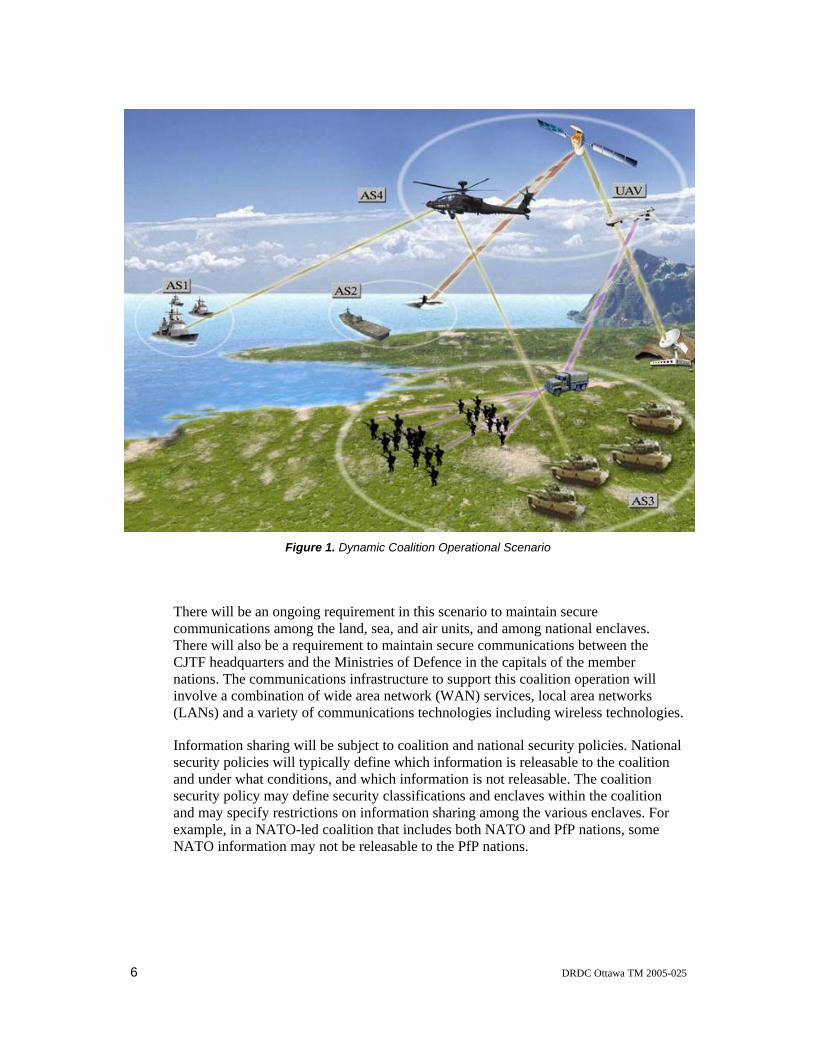
A typical multinational military coalition scenario involves the deployment of a multi-national Combined Joint Task Force (CJTF) comprising the land, sea, and air forces of the coalition member nations in a hostile region. In an example operational scenario, shown in Figure 1, the multinational CJTF will arrive by sea, with air support. Initially the CJTF headquarters will be on a ship. Air reconnaissance will be ongoing and land forces will be deployed to establish a land-based operation including mobile units. Eventually a CJTF headquarters may be established on land to direct further operations.
6 DRDC Ottawa TM 2005-025
Figure 1. Dynamic Coalition Operational Scenario
There will be an ongoing requirement in this scenario to maintain secure communications among the land, sea, and air units, and among national enclaves. There will also be a requirement to maintain secure communications between the CJTF headquarters and the Ministries of Defence in the capitals of the member nations. The communications infrastructure to support this coalition operation will involve a combination of wide area network (WAN) services, local area networks (LANs) and a variety of communications technologies including wireless technologies.
Information sharing will be subject to coalition and national security policies. National security policies will typically define which information is releasable to the coalition and under what conditions, and which information is not releasable. The coalition security policy may define security classifications and enclaves within the coalition and may specify restrictions on information sharing among the various enclaves. For example, in a NATO-led coalition that includes both NATO and PfP nations, some NATO information may not be releasable to the PfP nations.

DRDC Ottawa TM 2005-025 7
2.6.2 VPN Requirements
Using the coalition concepts and the dynamic coalition scenario described above, the following are considered a reasonable set of VPN requirements for a dynamic coalition:
• Communications among coalition members must be secured from external threats.
• Coalition members must have complete control over their own information technology resources and personnel involved in the coalition. Changes to either the resources or people accessing the coalition should not require further VPN policy negotiation with other parties.
• Coalition members should be able to deploy autonomously managed authentication schemes for authenticating their own users before providing access to the coalition resources.
• Users from one coalition member should not have to acquire new authentication credentials in order to access other coalition member resources. The distribution of new credentials can seriously hamper the rapid deployment of dynamic coalitions unless it can be done in a fully automated fashion.
• The establishment of a dynamic coalition should not require coalition members to alter their physical strategic information technology (IT) infrastructure. For example, membership in the coalition should not require the establishment of a physically isolated LAN. The deployment of mobile assets necessarily implies that IT assets are physically re-located and configured.
• The establishment of a dynamic coalition should not require a priori coordination of the logical strategic IT infrastructure. For example, it should be possible to establish a coalition without having to change a private IPv4 address space.
• It is highly desirable that a coalition party be able to audit the information exchanged as part of the coalition from its own coalition VPN gateway. Auditing at the gateway provides a more manageable scenario than auditing at all servers and edge-computing nodes within the party’s coalition committed assets. This implies that end-to-end IPsec tunnels cannot be used in some coalition scenarios.
• It is desirable that mobile coalition deployments have the option of using locally provided communications assets (for example, local public telephone infrastructure, Internet service provider (ISP), leased data lines, cellular network, etc.). Not all coalition parties that

8 DRDC Ottawa TM 2005-025
engage in mobile deployments will have autonomous WAN connectivity back to their strategic network (for example, using tactically deployed satellite). Hence, the outer (black) coalition addresses may be dynamically assigned from the local ISP IPv4 address pool.
• It is highly desirable that the security policy negotiation amongst coalition parties be implemented with the least amount of a priori knowledge. This does imply that coalition members implement standards which provide:
a. a high-level security policy language,
b. gateway discovery,
c. policy discovery,
d. policy distribution,
e. policy resolution,
f. a model to translate high-level policies to IPsec security associations (SAs), and
g. a means of checking compliance of SAs to the high-level policy.

DRDC Ottawa TM 2005-025 9
3. The DVC Design and Operation
3.1 Motivation
The X-Bone [4], developed by the Information Sciences Institute (ISI), is an experimental system that permits the automated deployment and management of virtual networks overlaid on top of a physical network infrastructure. Overlays can be used to develop new network and application services or for simply creating isolated infrastructures for restricted purposes. The X-Bone can create concurrent virtual networks topologies in star, ring, and bus configurations. The X-Bone builds its overlays using arbitrary nodes that it identifies via its discovery protocol; only X-Bone-capable nodes can participate in an overlay.
Defence R&D Canada (DRDC) recognized the potential of this technology to achieve rapid deployment of coalition VPNs. However, DRDC envisioned a system that included attached subnetworks in the VPN, that used filtering to create a truly closed logical network, and that identified the nodes that form the VPN instead of selecting them dynamically through the discovery protocol. Through past VPN initiatives, the management overhead of maintaining coherent VPN infrastructures was deemed very cumbersome and very labour intensive. DRDC believed that the use of technology similar to the X-Bone could greatly reduce this aspect of VPN operation.
DRDC proceeded to evolve the DVC concept and to develop a DVC prototype, based on X-Bone concepts and technology, which could demonstrate a possible solution for the rapid deployment of one or more dynamic coalition VPNs. In this concept, each partner in the VPN connects its participating network assets through a local DVC to the common WAN.
3.2 Design Principles
As a first step in evolving the DVC concept, a set of design principles was formulated to help guide the development of a prototype system. These design principles, as set out in this section of the report provided both a challenge to the development team and a measure that could be used to track the completeness of the implementation for the DVC.
The following basic design principles were adopted for the DVC:
1. Coalition partners would only need to maintain minimal high-level information about each other: who they are (a name) and where they are on the network (a network address).
2. A coalition partner would maintain access policies, which could be dynamic, for every other coalition partner, in a local policy database. These policies would describe, for a particular partner, which subnetworks that partner would have

10 DRDC Ottawa TM 2005-025
access to, what services would be available to that partner, and what domain name service (DNS) name bindings that partner would need to make use of the services. An access policy for a particular partner would be activated only when required and when authorized by local security officers.
3. To establish a VPN connection between two partners, both partners would authorize the creation of the VPN after examining the access policies of the other partner. To complete the establishment of a VPN connection, both partners would have to modify the configuration settings of their respective systems appropriately. This would involve changing the configuration settings for such elements as IPsec parameters, IP packet filters rules, routing tables, and DNS databases.
4. If a local partner in an established VPN modifies its local access policies for a remote partner, then the local partner would notify the remote partner and renegotiate the terms and conditions of the VPN connection with that partner.
5. If a local partner in an established VPN terminates the access of a remote partner, then the partner terminating the access would notify the remote partner and automatically terminate the VPN connection to that partner.
Table 1 compares the compliance of the DVC design with the general dynamic VPN requirements stated in Section 2.6. It can be seen that the DVC meets, at most, 7 of the 15 requirements listed, which is indicative of the experimental prototype nature of the DVC.
Table 1. DVC Compliance with Dynamic VPN Requirements
DYNAMIC VPN REQUIREMENTS DVC COMPLIANCE Y/N
Communications among coalition members must be secured from external threats.
The DVC system meets this requirement by using authenticated/secure communications channels to provide authenticity and privacy and by employing a firewall to control accessibility.
Y
Coalition members must have complete control over their own information technology resources and personnel involved in the coalition. Changes to either the resources or people accessing the coalition should not require further VPN policy negotiation with other parties.
The DVC system meets this requirement if the local coalition identifies all its possible resources to the coalition when the VPN is negotiated. If so, there would never by a requirement to re-negotiate the VPN policy.
The DVC system only processes network layer policies and as such, it does not track changes in personnel – only changes in network layer resources.
(Y)
Coalition members should be able to deploy autonomously managed authentication schemes for authenticating their own users before providing access to the coalition resources.
The DVC system does not include support for user level authentication schemes, but the DVC system does not preclude their use either.
N

DRDC Ottawa TM 2005-025 11
Table 1. DVC Compliance with Dynamic VPN Requirements
DYNAMIC VPN REQUIREMENTS DVC COMPLIANCE Y/N
Users from one coalition member should not have to acquire new authentication credentials in order to access other coalition member resources. The distribution of new credentials can seriously hamper the rapid deployment of dynamic coalitions unless it can be done in a fully automated fashion.
The DVC system does not include support for user authentication credentials, but the DVC system does not preclude their use either.
N
Coalition members must have complete control over their own information technology resources and personnel involved in the coalition. Changes to either the resources or people accessing the coalition should not require further VPN policy negotiation with other parties.
The DVC system meets this requirement since the policies exchanged between coalition members describe their respective IT infrastructure. Coalition members are not required to alter their physical strategic IT infrastructure in order to connect to the coalition VPN.
Y
Coalition members should be able to deploy autonomously managed authentication schemes for authenticating their own users before providing access to the coalition resources.
The DVC system meets this requirement since the policies exchanged between coalition members describe their respective IT infrastructure, including IP address space. Although the DVC system can detect conflicts in allocated IP address space, it does not employ mechanisms such as Network Address Translation (NAT) to resolve such conflicts.
Y
Users from one coalition member should not have to acquire new authentication credentials in order to access other coalition member resources. The distribution of new credentials can seriously hamper the rapid deployment of dynamic coalitions unless it can be done in a fully automated fashion.
The DVC system meets this requirement since the VPN tunnel terminates within the DVC system. As such, auditing can be done within the DVC system itself or in a system located within the “red” side of the local network infrastructure.
The use of end-to-end IPsec tunnels is controlled by policy and such tunnels must be explicitly permitted by the policy.
Y
Coalition members must have complete control over their own information technology resources and personnel involved in the coalition. Changes to either the resources or people accessing the coalition should not require further VPN policy negotiation with other parties.
The DVC system does not place any constraints on how the DVC attaches to the common “black” network. However, the address assigned to the public “black” DVC interface must be made known to the other coalition members in advance using out-of-band channels. The DVC system does not support auto-discovery of remote DVC systems and as such, the DVC system cannot easily support dynamically assigned addresses.
N

12 DRDC Ottawa TM 2005-025
Table 1. DVC Compliance with Dynamic VPN Requirements
DYNAMIC VPN REQUIREMENTS DVC COMPLIANCE Y/N
It is highly desirable that the security policy negotiation amongst coalition parties be implemented with the least amount of a priori knowledge. This does imply that coalition members implement standards which provide:
a. a high-level security policy language,
a. The DVC system provides a security policy language that requires only a small amount of a priori knowledge.
Y
b. gateway discovery, b. The DVC system does not include support for gateway discovery.
N
c. policy discovery, c. The DVC system does not include support for policy discovery.
N
d. policy distribution, c. The DVC system includes support for policy exchange during the on-line policy negotiation process
(Y)
e. policy resolution, e. The DVC system does not include support for policy resolution.
N
f. a model to translate high-level policies to IPsec security associations (SAs), and
f. The DVC system does not include a model to translate high-level policies to IPsec SAs.
N
g. a means of checking compliance of SAs to the high-level policy.
g. The DVC system does not include a means of checking compliance of SAs to the high-level policy.
N
(Y) indicates limited or conditional compliance
3.3 System Architecture
Figure 2 shows the system architecture of the DVC prototype. A central DVC process executes all DVC functions with the support of four subsystems:
• a Firewall subsystem,
• a Routing subsystem,
• a DNS subsystem, and
• an IPsec subsystem.
The DVC prototype also includes a web-based Management Console and a Policy Editor.

DRDC Ottawa TM 2005-025 13
A DVC operator can interact with, and control the operation of, the DVC through the Management Console to establish and dismantle VPNs to individual sites and to entire coalitions. The DVC Management Console also provides a graphical representation of each configured coalition showing all coalition member sites and the status of the VPN between each pair of DVCs. Section 5 describes the operation and use of the DVC Management Console in more detail.
A DVC security officer can create, install, and modify local security policies using the Policy Editor. The Policy Editor facilitates the compilation of DVC policies by requiring that objects representing local resources such as networks, name spaces (domains), services, servers, and permitted traffic be defined once and subsequently referenced within site level policies. This eliminates many of the problems resulting from erroneous data entry. Section 6 describes the operation and use of the DVC Policy Editor in more detail.
IPSec Tunnel
DVC Policy EditorDVC Management
Console
DVCSecurityOfficer
Firewall
DVC Process
DNS
Local Network
DVCOperator
Routing
IPSec
DVC System
Sub-Systems
DVC Control Session
Figure 2. DVC System Architecture
The DVC also requires the services of two logically independent certification authorities (CAs). One CA, local to the DVC, issues X.509 certificates to the DVC operators, the DVC security officers, and DVC internal processes, which are used to

14 DRDC Ottawa TM 2005-025
authenticate local console operations. The other CA is a project or coalition CA that issues X.509 certificates to the DVCs, which they use to authenticate to one another, when negotiating the establishment of VPN connections. Section 3.4.3 describes the CAs and the authentication processes in more detail.
3.4 Principles of Operation
3.4.1 Overview
The DVC prototype can establish a fully meshed VPN of point-to-point connections among a set of coalition member sites. A single VPN connection encrypts the traffic between two coalition sites. Traffic sent from one coalition site to another coalition site is never routed through a third coalition site. The DVC prototype uses secure authenticated out-of-band channels to establish, monitor, and dismantle the VPN connections.
The DVC views a coalition as a collection of sites with common security levels. VPNs can be created, dismantled, and monitored concurrently among these sites. With single Management Console commands, the DVC operator can instruct the DVC to establish a VPN to all sites in a coalition or to dismantle the VPN to all coalition sites. To support the monitoring and managing of coalition VPNs, the operator can view the status of all sites within a coalition on a single web page at the Management Console. In addition, the operator can also manage the VPNs for individual sites.
Each DVC maintains a DNS name, an IP address, and a security policy for every potential coalition partner. The security policies are stored in the local policy database. The DVC ensures that, when negotiating the establishment of a VPN connection, the IPsec parameters proposed by a remote DVC match those configured within the local database. The security policies allow the specification of mandatory and forbidden services, which the DVC uses to evaluate a proposed policy and either accept or reject the proposal.
If two DVCs authorize the creation of a VPN after examining the proposed policies received from the other coalition partner, both DVCs modify their respective configuration settings to permit the establishment of the VPN. This involves changing their IPsec settings, IP packet filter rules, routing tables, and DNS databases. The established VPN enforces both the local access policies defined in the local policy database as well as the remote access policies communicated by the remote DVC.
If a DVC in an established VPN changes the local access policies for a remote coalition partner in its local policy database, it notifies the remote DVC and renegotiates the VPN terms and conditions. If a DVC terminates a coalition partner’s access, it notifies the remote DVC and dismantles the VPN with that partner.

DRDC Ottawa TM 2005-025 15
Figure 3 illustrates a typical DVC deployment in a two-member coalition. The site security officer uses the DVC Policy Editor to create and install the security policy. The DVC operator uses the DVC Management Console to manage the VPNs. The DVC transmits security policies to remote peers, and receives and evaluates security policies from remote peers. When a decision has been made to create or dismantle a VPN, the DVC modifies the configuration of the IPsec, firewall, DNS, and routing sub-systems to enforce the local and remote security policies.
IPSec Tunnel
DVC Policy EditorDVC Management
DVCSecurityOfficer
Firewall
DVC Process
DNS
Local Network
DVCOperator
IPSec
DVC System
Sub-Systems
DVC Policy Editor DVC Management
DVCSecurityOfficer
Firewall
DVC Process
DNS
Local Network
DVCOperator
Routing
IPSec
DVC System
Sub-Systems
DVC Control Session
Routing
Figure 3. Typical DVC Deployment for a two member coalition
3.4.2 Establishing a VPN
When the DVC is instructed to establish a VPN with another site, through either a coalition or a site DVC Management Console operation, the DVC retrieves the policy information for the remote site from its local policy database. This information includes the IP address and the fully qualified domain name (FQDN) of the remote site, and identifies the local subnetworks that require access to the services offered by the remote site, as well as the

16 DRDC Ottawa TM 2005-025
local services that are offered to the remote site. The information also identifies the services that the remote site must offer to the local site and the services that the remote site must not offer to the local site.
After retrieving the policy information for the remote site, the initiating DVC sends a Propose message to the remote DVC over a mutually authenticated Transport Control Protocol (TCP) connection secured by the secure sockets layer (SSL) mechanism. The responding DVC evaluates the proposed policy by comparing it with the policy for the initiating DVC stored in its local policy database, and comparing the proposed services with the expected services configured for the initiating DVC. The responding DVC also checks that the proposed networks and the DNS do not conflict with any other VPN. If the responding DVC rejects the policy, it sends a Deny message to the initiating DVC and closes the SSL connection. If the responding DVC accepts the proposed policy, it sends an Apropose message to the initiating DVC to acknowledge that it has accepted the proposed policy. The Apropose message also contains a reciprocal policy proposal from the responding DVC to the initiating DVC.
The initiating DVC evaluates the proposed policy received in the Apropose message in the same manner as was done by the responding DVC. Again, a decision is made to either accept or reject the proposed policy. If the initiating DVC rejects the policy, it sends a Deny message to the responding DVC and closes the SSL connection. If the initiating DVC accepts the proposed policy, it sends an Accept message to the responding DVC to acknowledge that it has accepted proposed policy. The Accept message also contains the key material to be used to establish the VPN. Once the initiating DVC has sent the Accept message and the responding DVC has received the Accept message, both DVCs begin to implement the amalgamated policy.
The DVC includes four sub-systems that it uses to implement the amalgamated policy. The IPsec sub-system creates the VPN between the two DVCs. The firewall sub-system filters the traffic in and out of the VPN so that only traffic configured in the policy is allowed across the VPN. The DNS sub-system supplies the name bindings required to access the services offered by the remote site. The routing sub-system advertises the remote networks accessible via the VPN.
Figure 4 illustrates the communication between two DVC systems and their respective DVC operators when establishing a single VPN between two DVC systems.

DRDC Ottawa TM 2005-025 17
Browser
DVC Operator
Browser
DVC OperatorSSL HTTPS/SSLHTTPS/SSL
DVC“A”
DVC“B”
CONNECT
1
PolicyProposal
2
PolicyProposal withAcknowledge
4
EvaluatePolicy
5
EvaluatePolicy
3
Acknowledge
6
ReconfigureSub-Systems
7ReconfigureSub-Systems
7
Figure 4. Establishing a VPN
Table 2 lists the steps involved when establishing a single VPN between two DVC systems.
Table 2. Steps to create a VPN
STEP ACTION
Step #1 The DVC operator for DVC “A” issues a command to connect to DVC “B” or to an entire coalition.
Step #2 DVC “A” establishes an SSL session to DVC “B” and proposes its policy configured for DVC “B”.
Step #3 DVC "B" evaluates the policy proposed by DVC "A" against the locally configured policy for DVC "A". If the proposed policy is acceptable, DVC "B" proceeds to Step #4, otherwise DVC "B" rejects the proposed policy.
Step #4 DVC “B” acknowledges the policy proposed by DVC “A” and proposes its policy configured for DVC “A”.
18 DRDC Ottawa TM 2005-025
Step #5 DVC "A" evaluates the policy proposed by DVC "B" against the locally configured policy for DVC "B". If the proposed policy is acceptable, DVC "A" proceeds to Step #6, otherwise DVC "A" rejects the proposed policy.
Step #6 DVC “A” acknowledges the policy proposed by DVC “B”. The SSL session is closed.
Step #7 The SSL session is closed. Both DVC systems reconfigure their sub-systems to establish the VPN.
Each interaction between the DVC operator and the DVC requires the establishment of a new SSL session by the DVC operator’s browser and the DVC Apache web server. Steps #2, #4 and #6 make use of a single SSL session between the two DVCs.
3.4.3 Authentication
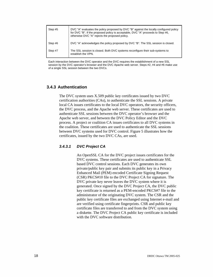
The DVC system uses X.509 public key certificates issued by two DVC certification authorities (CAs), to authenticate the SSL sessions. A private local CA issues certificates to the local DVC operators, the security officers, the DVC process, and the Apache web server. These certificates are used to authenticate SSL sessions between the DVC operator’s browser and the Apache web server, and between the DVC Policy Editor and the DVC process. A project or coalition CA issues certificates to all DVC systems in the coalition. These certificates are used to authenticate the SSL sessions between DVC systems used for DVC control. Figure 5 illustrates how the certificates, issued by the two DVC CAs, are used.
3.4.3.1 DVC Project CA
An OpenSSL CA for the DVC project issues certificates for the DVC systems. These certificates are used to authenticate SSL based DVC control sessions. Each DVC generates its own private/public key pair and submits its public key in a Privacy Enhanced Mail (PEM) encoded Certificate Signing Request (CSR) PKCS#10 file to the DVC Project CA for signature. The DVC private key never leaves the DVC system where it is generated. Once signed by the DVC Project CA, the DVC public key certificate is returned as a PEM-encoded PKCS#7 file to the administrator of the originating DVC system. The CSR and the public key certificate files are exchanged using Internet e-mail and are verified using certificate fingerprints. CSR and public key certificate files are transferred to and from the DVC system using a diskette. The DVC Project CA public key certificate is included with the DVC software distribution.

DRDC Ottawa TM 2005-025 19
DVC “A” DVC “B”
DVC Operator “A”Browser
DVC Operator “B”Browser
DVC Process DVC Process .
Apache Web Server Apache Web Server
HTTPS/SSL HTTPS/SSL
SSL
DVC Project CA
DVC “A”Private CA
DVC “B”Private CA
DVC “A”Policy Editor
SSL
DVC “B”Policy Editor
SSL
Figure 5. DVC Certificate Usage
3.4.3.2 Local DVC CA
Each DVC system establishes and operates a private OpenSSL CA that issues X.509 public key certificates to the DVC Apache web server, the DVC process, the DVC operators, and the security officers. These certificates are used to authenticate the DVC operators and security officers to the Apache web server and to the DVC process. One DVC operator certificate is issued by the DVC software installation script. A script is also provided to issue additional DVC operator certificates after the system is operational. In either case, a password protected PKCS#12 file, which contains both a private/public key pair and signed public certificate, is provided to the DVC operator. The DVC operator transfers the PKCS#12 file to the operator’s workstation using a floppy disk.

20 DRDC Ottawa TM 2005-025
3.4.4 Health Monitoring and Status Reporting
Each DVC monitors the health of established VPNs with the ping command, which reports packet loss and round-trip times. The ICMP ECHO REQUEST packets are sourced from the local DVC’s internal network interface and are addressed to the remote DVC’s internal network interface. This causes the packets to be encrypted and delivered within the IPsec tunnel between the two DVC systems. When the health monitoring system reports five consecutive polls yielding 100% packet loss, the DVC marks the VPN as down and dismantles the VPN. The DVC periodically attempts to re-establish the failed VPN.
Each DVC also reports status to other active DVCs using a Status message that includes the health monitoring information collected by the local DVC. This enables each DVC to determine the health of the entire coalition.
3.4.5 Dismantling a VPN
When the DVC is instructed to dismantle a VPN with another site, through either a coalition or a site DVC Management Console operation, it sends a Delete message to the responding DVC. Once the initiating DVC has sent the Delete message and the responding DVC has received the Delete message, both DVCs cease to enforce the policy. All sub-systems are reconfigured to dismantle the VPN and remove the site-specific configuration.
Figure 6 illustrates the communication between two DVC systems and their respective DVC operators when dismantling a single VPN between two DVC systems.

DRDC Ottawa TM 2005-025 21
Browser
DVC Operator
Browser
DVC OperatorSSL HTTPS/SSLHTTPS/SSL
DVC“A”
DVC“B”Delete
2DELETE
1
ReconfigureSub-Systems
3ReconfigureSub-Systems
3
Figure 6. Dismantling a VPN
Table 3 list the steps required when dismantling a single VPN between two DVC systems.
Table 3. Steps to dismantle a VPN
STEP ACTION
Step #1 The DVC operator for DVC “A” issues a command to delete the VPN to DVC “B” or to dismantle an entire coalition.
Step #2 DVC “A” establishes an SSL session to DVC “B” and instructs DVC “B” to dismantle the VPN to DVC “A”.
Step #3 The SSL session is closed. Both DVC systems reconfigure their subsystems to dismantle the VPN.

22 DRDC Ottawa TM 2005-025
3.5 Evolution of the DVC
The DVC system has undergone numerous changes and enhancements since the system was first conceived.
The role of the DVC operator has changed considerably since the DVC was first demonstrated. Initially, the DVC was not able to evaluate proposed policies because it could not specify mandatory and forbidden services. Instead, the DVC operator evaluated the proposed policies and made the decision to either accept or reject the proposed policies. This proved to be inefficient, as the creation of a VPN would be delayed if a DVC operator were unavailable. To mitigate this problem, policy caching was introduced and the DVC system was modified to accept a proposed policy automatically if an identical cached version of the policy was available. When the DVC operator accepted a proposed policy, it was cached for future comparisons with proposed policies. This still required the DVC operator to be present the first time the VPN was established, and each time the proposed policy was changed. The current DVC system evaluates proposed policies without DVC operator assistance by comparing the proposed policies against the expected services configured for the remote peer.
To facilitate demonstrations, previous versions of the DVC included a special capability to allow a single DVC operator to initiate the establishment of a fully meshed coalition VPN. Once the DVC successfully negotiated a VPN with a remote peer, it sent a policy proposal to the remaining coalition members. With the use of the cached policies evaluation model, the coalition-wide VPN could be established with one DVC operator action. Since this is not a typical concept of military operations, the capability was later removed.
The original IPsec subsystem incorporated the Internet Security Association and Key Management Protocol (ISAKMPD) Internet Key Exchange (IKE) daemon to exchange dynamic key material. Unfortunately, ISAKMPD experienced instabilities for both IKE and IPsec security associations once the DVC was deployed in a larger coalition. ISAKMPD was removed from the DVC and the system was modified to use static key material for IPsec security associations. The key material is generated by the initiating DVC and sent within the Accept message to the responding DVC.
The DVC was originally developed only to support the Internet Protocol Version 4 (IPv4). Since several foreign R&D organizations were interested in deploying the DVC in Internet Protocol Version 6 (IPv6) networks, the DVC was enhanced to support both IPv4 and IPv6.
Initially, the DVC was implemented as a single Perl program (see Section 4). However, as enhancements were introduced, the DVC Perl program grew until it became unmanageable and difficult to test. The DVC program was subsequently restructured by removing the subsystems from the main DVC program. New self-contained subsystems were implemented as separate modules. These self-contained subsystem modules maintain the state of the subsystem. The main DVC program

DRDC Ottawa TM 2005-025 23
interacts with the subsystem modules through an interface with well-defined data structures (Section 4.6)
During the initial development of the DVC, the DVC Policy Configuration File used a custom format that required a custom parser to process the file. To add more structure and definition to the DVC Policy Configuration File, without adding to the complexity required to process the file, the format was changed to an eXtensible Markup Language (XML) format. An XML schema ensures that the data is well formed.
Although XML is both human and machine readable, the security officer does not manipulate the XML file directly and therefore does not require any knowledge of XML. The DVC Policy Editor was produced to allow the DVC security officer to create and install the DVC policy configuration remotely. The DVC Policy Editor facilitates the compilation of DVC policies by requiring that objects representing local resources such as networks, name spaces (domains), services, servers, and permitted traffic, be defined once and subsequently referenced within site level policies. This eliminates many of the problems that originate from erroneous data entry.

24 DRDC Ottawa TM 2005-025
4. The DVC Implementation
4.1 Overview
The DVC prototype is based on the FreeBSD-4.6 operating system running on an Intel-based PC. Table 20 in Annex A lists all of the software components included in the DVC implementation.
The DVC prototype system is implemented as a main DVC process with four subsystems:
• a Firewall subsystem,
• a Routing subsystem,
• a DNS subsystem, and
• an IPsec subsystem.
The main DVC process and the subsystems are implemented as independent modules.
The DVC system configuration is controlled by three files: a DVC configuration file, a DVC Policy Configuration File, and a DVC security class file. These files are described in Annex B.
The DVC system installation procedure is described in Annex C and the system configuration procedure is described in Annex D.
4.2 The DVC Process
The DVC process, which implements all DVC functions, is written in Perl. The process is an event driven process that uses the Perl Select Object to detect events. The Perl Select Object uses the Unix Select system call to detect communication requests from other DVC components. All DVC events are in the form of the network connections listed in Table 4.

DRDC Ottawa TM 2005-025 25
Table 4. DVC Communication
TYPE PORT DVC COMPONENT
TCP 2000 DVC Management Console
TCP/SSL 2001 DVC Policy Editor
TCP/SSL 2020 DVC Process
The Perl Select Object manages the TCP connections from the DVC Management Console. However, the Perl Select Object cannot manage the TCP/SSL connections from the DVC Policy Editor and from other DVC systems, because the connection identifier returned by the Perl SSL module, known as a “handle”1, is not the standard handle object understood by the operating system. Although the handle for the underlying TCP connection is a standard operating system handle, using this handle may cause the DVC process to block unexpectedly within the Perl SSL module. Therefore, the DVC process forks a child process to respond to an incoming TCP/SSL connection and then establishes a Unix pipe between itself and the child process. The Perl Select Object uses the pipe to manage the connection.
The DVC process waits in the Perl Select Object for an event to occur. If no event occurs after a specific period, the DVC process exits the Perl Select Object and performs health monitoring, transmits status messages, and/or refreshes the sub-systems as required. Following these tasks, the DVC process returns to the Perl Select Object and repeats the cycle.
4.3 DVC to DVC Communications
The DVC process communicates with a remote DVC over a secure TCP connection to port 2020. The connection is mutually authenticated using X.509 certificates issued by the Project CA, and is secured using SSL. When the connection is established, the DVC process spawns an SSL child process to handle the communication with the remote peer.
The DVC process communicates with the child process using a pipe. The child process alternates between reading from the pipe and writing to the SSL connection, and reading from the SSL connection and writing to the pipe. The child process monitors the data stream from the pipe for commands from the DVC process to close the SSL connection. The child process also injects messages into the data stream to notify the DVC process of errors.
1 The “handle” is equivalent to a Unix file descriptor, which is an internal identifier the system uses to manage input-output operations.

26 DRDC Ottawa TM 2005-025
4.3.1 DVC-to-DVC Message Formats
The DVC-to-DVC communication is in the form of XML encoded messages exchanged over mutually authenticated SSL connections. The messages contain policy proposals, status reports, and commands to remote peers to setup, monitor, and dismantle VPNs.
There are two categories of DVC messages: SSL messages and PIPE messages.
SSL messages are exchanged between remote peers. These messages are transmitted and received by the SSL child processes but are not interpreted by the child processes.
PIPE messages are used for communication between the DVC process and the child SSL process. These messages allow the DVC process to control the child process and the child process to signal errors to the DVC process.
Figure 7 illustrates the XML schema design view of a DVC message’s child elements.
Figure 7. DVCCmd
The SSL message can contain one of seven messages (listed in Table 5). Figure 8 illustrates the XML schema design view of the SSL message child elements.

DRDC Ottawa TM 2005-025 27
Figure 8. SSLCmd
Table 5 lists all seven SSL messages and gives a brief description of the message function.
Table 5. Remote DVC Messages
MESSAGE COMMENT
PROPOSE The Propose message is sent from the initiating DVC to the responding DVC. This message is used to send a policy proposal to a remote peer during the establishment of a VPN.
APROPOSE The Apropose message is sent from the responding DVC to the initiating DVC. This message is used to acknowledge the acceptance of the initiator’s proposed policy and to propose a reciprocal policy to the initiating DVC.
ACCEPT The Accept message is sent from the initiating DVC to the responding DVC. This message is used to acknowledge the acceptance of the responder’s proposed policy and to exchange key material.
DENY The Deny message is sent from either DVC to reject a proposed policy.
DELETE The Delete message is sent from either DVC. This message warns that the VPN will be dismantled.
STATUS The Status message is sent from either DVC. This message is used to propagate status of site VPNs to other members of the coalition.
ERROR The Error message is sent from either the initiating or responding DVC. This message indicates that an error has occurred in the negotiation of the VPN.
The PIPE message can contain one of three messages (listed in Table 6). Figure 9 illustrates the XML schema design view of the PIPE message child elements.

28 DRDC Ottawa TM 2005-025
Figure 9. PIPECmd
Table 6 lists all three PIPE messages and gives a brief description of the message function.
Table 6. Local DVC Messages
MESSAGE COMMENT
CLOSE The Close message is sent either from the DVC process or from the SSL child process. If the message is from the DVC process, it instructs the SSL child process to close the SSL connection. If the message is from the SSL child process, it serves to notify the DVC process that the SSL connection has closed.
PINGREPLY The Pingreply message is sent from the health monitoring child process to the DVC Process. This message contains the results of health monitoring.
LOCALERROR The Localerror message is sent from the SSL child process to the DVC Process. The message notifies the DVC process that an error has occurred in the SSL child process.
4.3.1.1 Propose Policy
The Propose message, sent from an initiating DVC to a responding DVC, is used to send a policy proposal to a remote peer to initiate the establishment of a VPN. Figure 10 illustrates the XML schema design view of the entire Propose message.
The Propose message contains:
• the FQDN of the initiating DVC,
• a unique policy Identification number,
• an IPv4 and/or an IPv6 Internal Address,
• the Local policy configuration, and
• the local Security class.

DRDC Ottawa TM 2005-025 29
The local policy configuration is taken from the Local element defined in the DVC Policy Configuration File. The structure of this element is described in Section 6.2.2.3.
The local security class is taken from the Security element defined in the DVC Policy Configuration File. The structure of this element is described in Section 6.2.2.1.
Figure 10. Propose
4.3.1.2 Accept Propose Policy
The Apropose message, sent from a responding DVC to an initiating DVC, is used to acknowledge the acceptance of the initiator’s proposed policy and to propose a reciprocal policy to the initiating DVC. Figure 11 illustrates the XML schema design view of the entire Apropose message.
The APropose message contains:
• the FQDN of the responding DVC,
• a unique Policy Identification number,
• an IPv4 and/or an IPv6 Internal Address, and

30 DRDC Ottawa TM 2005-025
• the Local policy configuration.
The local policy configuration is taken from the Local element defined in the DVC Policy Configuration File. The structure of this element is described in Section 6.2.2.3.
Figure 11. Apropose
4.3.1.3 Accept
The Accept message, sent from the initiating DVC to the responding DVC, is used to acknowledge the acceptance of the responder’s proposed policy and to exchange key material. Figure 12 illustrates the XML schema design view of the entire Accept message.
The Accept message contains:
• the FQDN of the initiating DVC,
• a unique Policy Identification number,
• the Local SPI and key material, and
• the Remote SPI and key material.
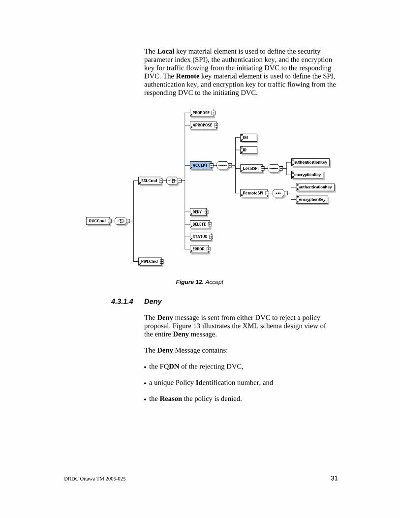
DRDC Ottawa TM 2005-025 31
The Local key material element is used to define the security parameter index (SPI), the authentication key, and the encryption key for traffic flowing from the initiating DVC to the responding DVC. The Remote key material element is used to define the SPI, authentication key, and encryption key for traffic flowing from the responding DVC to the initiating DVC.
Figure 12. Accept
4.3.1.4 Deny
The Deny message is sent from either DVC to reject a policy proposal. Figure 13 illustrates the XML schema design view of the entire Deny message.
The Deny Message contains:
• the FQDN of the rejecting DVC,
• a unique Policy Identification number, and
• the Reason the policy is denied.

32 DRDC Ottawa TM 2005-025
Figure 13. Deny
4.3.1.5 Delete
The Delete message, sent from either DVC, warns that the VPN will be dismantled. Figure 14 illustrates the XML schema design view of the entire Delete message.
The Delete message contains the FQDN of the initiating DVC.

DRDC Ottawa TM 2005-025 33
Figure 14. Delete
4.3.1.6 Status
The Status message is sent from a DVC to propagate status of its site VPNs to other members of the coalition. Figure 15 illustrates the XML schema design view of the entire Status message.
The Status message contains:
• the FQDN of the initiating DVC, and
• one or more Site Status elements.
Each Site Status element contains:
• the Round Trip Time (RTT), in milliseconds, for the site, and
• the Packet Loss percentage for the site.

34 DRDC Ottawa TM 2005-025
Figure 15. Status
4.3.1.7 Error
The Error message is sent from either DVC to indicate that an error has occurred in the negotiation of the VPN. Figure 16 illustrates the XML schema design view of the entire Error message.
The Error message contains:
• the FQDN of the DVC reporting the error, and
• the Reason for the error.

DRDC Ottawa TM 2005-025 35
Figure 16. Error
4.3.1.8 Close
The Close message is sent either from the DVC process or from the SSL child process. If the message is sent from the DVC process, it instructs the SSL child process to close the SSL connection. If the message is sent from the SSL child process, it notifies the DVC process that the SSL connection has closed. Figure 17 illustrates the XML schema design view of the entire Close message.
The Close message contains:
• the FQDN of the DVC for which the session closed, and
• the Reason the session was closed.

36 DRDC Ottawa TM 2005-025
Figure 17. Close
4.3.1.9 Pingreply
The Pingreply message, sent from the health monitoring child process to the DVC process, contains the results of health monitoring. Figure 18 illustrates the XML schema design view of the entire Pingreply message.
The Pingreply message contains the Site Status element.
The Site Status element contains:
• the Round Trip Time (RTT), in milliseconds, for the site, and
• the Packet Loss percentage for the site.
Figure 18. Pingreply
4.3.1.10 Localerror
The Localerror message, sent from the SSL child process to the main DVC process, notifies the DVC process that an error has occurred in the SSL child process. Figure 19 illustrates the XML schema design view of the entire Localerror message.

DRDC Ottawa TM 2005-025 37
The Localerror message contains:
• the FQDN of the DVC for which the error occurred, and
• the Reason the error occurred.
Figure 19. Localerror
4.4 DVC Management Communication
The DVC operator interacts with the DVC using the DVC Management Console (described in Section 5). The DVC Management Console sends commands (described in Section 5.2) to the DVC process over a connection on TCP port 2000. This connection uses the loopback interface and IP-based authentication. Since the DVC Management Console is co-located on the same system as the DVC process, the TCP socket is created to accept only connections from the loopback address. This ensures that the DVC process only accepts connections that are associated with authenticated web sessions between the DVC operator and the DVC Management Console.
4.5 Configuring the DVC
4.5.1 DVC Configuration
A DVC system configuration script is provided with the DVC software distribution to configure the DVC system once the software has been installed. Annex D outlines the use of the DVC system configuration script. Annex B illustrates a sample of the DVC configuration file that is produced by the DVC system configuration script.

38 DRDC Ottawa TM 2005-025
4.5.2 Policy Configuration
When the system is started, the DVC process loads the DVC Policy Configuration File from the system disk and initializes the local policy database for each coalition and its configured member sites. An example of a Policy Configuration File is shown in Annex H. If the Policy Configuration File cannot be found on the system disk, then the DVC process must wait for the DVC Policy Editor to push a Policy Configuration File to the DVC process.
The DVC Policy Configuration File is imported from the DVC Policy Editor (Section 6) over a secure TCP connection initiated by the Policy Editor to TCP port 2001. The TCP connection is mutually authenticated using X.509 certificates issued by the local CA, and is secured using SSL. When the connection is established, the DVC process spawns an SSL child process to communicate with the Policy Editor.
The child process loads the policy file from the DVC Policy Editor over the secure connection, writes the data to a temporary file, resets a file-based flag, notifies the main DVC process with a Unix HUP signal, and then begins to poll the file-based flag. When the flag changes to indicate that the main DVC process has finished processing the policy, the child process returns either a positive or a negative response to the Policy Editor and closes the SSL session.
When the DVC process receives the HUP signal, it loads the new policy from the temporary file and parses the policy. If the file does not parse successfully, the DVC process discards the new policy and indicates the error using the file-based flag (which the child process is polling). If the policy parses successfully, then the DVC process sets the file-based flag to indicate success and proceeds to install the policy. The DVC process compares the new policy with the existing policy, adds any new sites and coalitions, and removes any old sites and coalitions. The DVC process also re-negotiates any existing VPN connections to sites or coalitions whose policies have changed.
4.6 DVC Subsystem Management
The DVC process manages the Firewall, Routing, DNS, and IPsec subsystems by invoking each subsystem’s Start, Stop, and Process functions.
When the DVC process starts, it calls the Start function for each subsystem to initialize the subsystem and place it into a known state.
The DVC process uses the Process function to configure the subsystem. The DVC process passes the configuration data, obtained from the local policy database, to the Process function in a well-defined data structure that is different for each subsystem.

DRDC Ottawa TM 2005-025 39
Each subsystem verifies the data to ensure that it does not produce configuration errors in the subsystem.
When the DVC process shuts down, before exiting, it calls the Stop function for each subsystem, to remove the configuration for the active subsystem.
4.6.1 The Firewall Subsystem
4.6.1.1 Description and Data Structure
The Firewall subsystem maintains two configuration files:
• ipf.rules.add, and
• ipf6.rules.add.
Table 7 highlights the composition of the data structure passed from the main DVC process to the Firewall subsystem. The Firewall Process function accepts an array of these data structures as its input parameters.
The sub-system decides which file should be used by testing the type of IP address specified in each element. If the element references Internet Protocol version 4 (IPv4) addresses, the rule is placed in the ipf.rules.add file. If the element references Internet Protocol version 6 (IPv6) addresses, the rule is placed in the ipf6.rules.add file. If the element contains a mix of IPv4 and IPv6 addresses, the sub-system returns an error.
Table 7. Firewall Subsystem Data Structure
FIELD DESCRIPTION
Command Operation Type (ADD, DELETE).
Action Rule action (pass, block).
direction Rule direction (in, out.)
interface Interface to which the rule applies.
Proto Protocol (tcp, udp, icmp)
Source Source IP Address
source_port Source Port number or name
source_port_match Source Port range operator (eq, le, lt, ge, gt)
Dest Destination IP Address

40 DRDC Ottawa TM 2005-025
dest_port Destination Port number or name
dest_port_match Destination Port range Operator (eq, le, lt, ge, gt)
established Is the rule for established connections (1=yes 0=no)
icmp_type ICMP Type
The Firewall subsystem is implemented using the IP Filter package, which uses American Standard Code for Information Interchange (ASCII) configuration files. The Firewall subsystem could also have been implemented using other packet filtering packages such as the FreeBSD IPFW kernel packet filter.
4.6.1.2 Initial Configuration
The operating system run-control scripts load the initial IP Filter configuration at boot time. The Firewall subsystem only permits SSL-based DVC control sessions on its external network interface to and from remote peers that have been configured in the local policy database. In addition, the Firewall subsystem only permits the following sessions on its internal network interface:
• Secure Hypertext Transfer Protocol (HTTPS) to TCP port 2000 (DVC Management Console),
• SSL to TCP Port 2001 (DVC Policy Editor),
• NTP
• DNS queries, and
• Secure Shell (SSH) (for management).
4.6.1.3 Run-Time Configuration
When the DVC successfully exchanges security policies with a remote peer and is ready to establish a VPN to the coalition member, the DVC process instructs the Firewall subsystem to expand the filters on the external network interface to permit encapsulated security payload (ESP) packets to and from the remote peer. In addition, the DVC process instructs the Firewall subsystem to expand the filters on the internal network interface to implement and enforce both the local and remote security policies. When a VPN to a coalition member must be dismantled, the DVC process instructs the Firewall subsystem to delete the

DRDC Ottawa TM 2005-025 41
associated filter rules from the IP Filter configuration file. After the files are modified, the Firewall subsystem reloads the filter lists using the ipf command.
4.6.2 The Routing Subsystem
4.6.2.1 Description and Data Structure
The Routing subsystem maintains the Zebra routing daemon configuration. The subsystem accesses the daemon using a telnet interface similar to the Cisco IOS.
Table 8 highlights the composition of the data structure passed from the main DVC process to the Routing subsystem. The Routing Process function accepts an array of these data structures as its input parameters.
Table 8. Routing Subsystem Data Structure
FIELD DESCRIPTION
command Operation (ADD, DELETE)
target Route Target
gateway Gateway Address
The Routing subsystem is implemented using the Zebra routing protocol package. Zebra uses ASCII configuration files, but its configuration can also be modified at run-time using a command interface similar to that of the Cisco IOS. Currently, DVC system only supports the Open Shortest Path First (OSPF) routing protocol. Zebra also supports the Routing Information Protocol (RIP – both version 1 and version 2) for intra-domain routing.
4.6.2.2 Initial Configuration
The operating system run-control scripts start the Zebra main process and the OSPF process at boot time. The Routing subsystem is configured to listen for routing updates (OSPF link state advertisements) after the system boots. The Routing subsystem does not generate any routing updates, unless the DVC process has configured it to do so.
42 DRDC Ottawa TM 2005-025
4.6.2.3 Run-Time Configuration
The DVC process establishes TCP connections to both the Zebra main process and the Zebra OSPF process and uses a command interface similar to that of the Cisco IOS to make the required configuration changes.
When the DVC successfully exchanges security policies with a remote peer and is ready to establish a VPN to the coalition member, the DVC process instructs the Routing subsystem to reconfigure the Zebra main process to add static routes for the remote networks accessible through the VPN. In addition, the DVC process instructs the Routing subsystem to reconfigure the Zebra OSPF process to advertise those static routes as Autonomous System External (ASE) Type-1 link state advertisements within the local OSPF routing domain. This causes packets destined for the remote networks to be delivered to the internal network interface of the DVC system. Otherwise, those packets would likely be routed using the routing domain’s default route. When a VPN to a coalition member must be dismantled, the DVC Process instructs the Routing subsystem to remove the static routes and associated OSPF link state advertisements.
4.6.3 The DNS Subsystem
The DNS subsystem is implemented using the Bind daemon, which uses ASCII configuration files. The main configuration file (named.conf) identifies the zones (domains) for which the name server is authoritative. Individual zone files contain the name bindings for the zone.
4.6.3.1 Description and Data Structure
The DNS subsystem provides access to name bindings for remote coalition sites by establishing itself as a primary authoritative name server for the remote domains. Internal systems must somehow be configured to use the DNS server on the DVC system for name resolution. This can be achieved by configuring clients to send queries directly to the DVC system or by configuring internal DNS servers to forward client queries to the DVC system.
The DNS subsystem maintains two types of configuration files:
• the Bind configuration file (named.conf), and
• zone files.

DRDC Ottawa TM 2005-025 43
Table 9 highlights the composition of the data structure passed from the main DVC process to the DNS subsystem. The DNS Process function accepts an array of these data structures as its input parameters.
Table 9. DNS Subsystem Data Structure
FIELD DESCRIPTION
command Operation Type (ADD, DELETE).
type Type of entry (SOA, A, AAAA, PTR).
domain Name of the domain to be added.
name Host name of the DNS Record.
address Host address of the DNS Record.
originhost Hostname of the primary server for the domain.
mailto E-Mail address of the individual responsible for the domain.
ns Name Server Resource Record.
mx Mail Exchanger Resource Record.
mxpref Preference for the Mail Exchanger Resource Record.
ttl Time to Live for the zone Start Of Authority (SOA) Record.
refresh Refresh Time for the zone SOA Record.
retry Retry Time for the zone SOA Record.
expire Expire time for the zone SOA Record.
minttl Minimum Time to Live for the zone SOA Record.
4.6.3.2 Initial Configuration
The operating system run-control scripts start the DNS process (named) at boot time. After the system boots, the DNS subsystem is only authoritative for locally defined domains.
4.6.3.3 Run-Time Configuration
When the DVC successfully exchanges security policies with a remote peer and is ready to establish a VPN to the coalition member, the DVC process instructs the DNS subsystem to create a zone file for each remote domain and populates the zone file

44 DRDC Ottawa TM 2005-025
with the name bindings included in the security policies retrieved from the coalition member. The DVC process also instructs the DNS subsystem to modify the named.conf file to establish itself as a primary authoritative name server for the remote domains. When a VPN to a coalition member must be dismantled, the DVC process instructs the DNS subsystem to delete the zone files associated with the remote domains and remove itself as an authoritative name server for the remote domains. After it modifies the files, the DNS subsystem stops and restarts the named process.
4.6.4 The IPsec Subsystem
4.6.4.1 Description and Data Structure
The DVC system exchanges static key material, generated by the IPsec subsystem, over an authenticated SSL channel. Two subsystem utility functions allow the DVC process to import the static key material from, and export the static key material to, the IPsec subsystem.
The IPsec subsystem maintains two kernel databases:
• the Security Association Database (SAD), and
• the Security Policy Database (SPD).
Table 10 highlights the composition of the data structure passed from the main DVC process to the IPsec subsystem. The IPsec Process function accepts an array of these data structures as its input parameters.
Table 10. IPsec Subsystem Data Structure
FIELD DESCRIPTION
command Operation Type (ADD, DELETE).
type Database Entry Type (SA, SP).
leaddr Local External Address.
readdr Remote External Address.
ospi Outbound SPI.
ispi Inbound SPI.
IPsecproto IPsec Protocol (esp, ah).
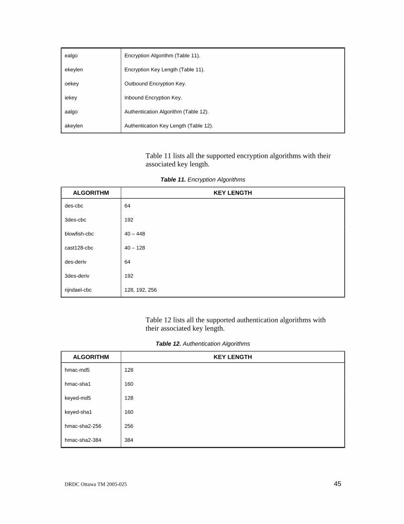
DRDC Ottawa TM 2005-025 45
ealgo Encryption Algorithm (Table 11).
ekeylen Encryption Key Length (Table 11).
oekey Outbound Encryption Key.
iekey Inbound Encryption Key.
aalgo Authentication Algorithm (Table 12).
akeylen Authentication Key Length (Table 12).
Table 11 lists all the supported encryption algorithms with their associated key length.
Table 11. Encryption Algorithms
ALGORITHM KEY LENGTH
des-cbc 64
3des-cbc 192
blowfish-cbc 40 – 448
cast128-cbc 40 – 128
des-deriv 64
3des-deriv 192
rijndael-cbc 128, 192, 256
Table 12 lists all the supported authentication algorithms with their associated key length.
Table 12. Authentication Algorithms
ALGORITHM KEY LENGTH
hmac-md5 128
hmac-sha1 160
keyed-md5 128
keyed-sha1 160
hmac-sha2-256 256
hmac-sha2-384 384

46 DRDC Ottawa TM 2005-025
hmac-sha2-512 512
The IPsec subsystem is implemented using KAME IPsec, which is included with FreeBSD-4.6. The FreeBSD kernel maintains two databases that contain the security associations (SAs) and the security policies (SPs). The security association database (SAD) contains the security parameters associated with each active SA. This includes the tunnel endpoint addresses, the security protocol, and the key material required to encrypt and decrypt packets over the SA. The security policy database (SPD) specifies the processing to be applied to each outgoing and incoming IP packet, thereby determining which packets can use the VPN. These kernel databases are modified using the FreeBSD setkey command.
4.6.4.2 Initial Configuration
When the system boots the SAD and SPD are empty.
4.6.4.3 Run-Time Configuration
When the DVC successfully exchanges security policies with a remote peer and is ready to establish a VPN to the coalition member, the DVC process instructs the IPsec subsystem to add the required configuration to the SAD and SPD using the setkey command. When a VPN to a coalition member must be dismantled, the DVC process instructs the IPsec subsystem to delete the associated configuration items from the SAD and SPD Kernel databases using the setkey command.
4.7 Network Communications
4.7.1 External Communication Requirements
The DVC system requires that one of the external interfaces be connected to a common wide area network such as the Internet. The DVC system uses the ports and protocols listed in Table 13. It should be verified that these ports and protocols are not blocked by any routers or firewalls.
Table 13. External Communication Requirements
INTERFACE PROTOCOL PORT INITIATED APPLICATION USE
External TCP 2020 IN/OUT DVC Process DVC Control sessions
Internal TCP 2000 IN Apache/Mod_SSL DVC Management Console

DRDC Ottawa TM 2005-025 47
Internal TCP 2001 IN DVC Process DVC Policy Editor
External IPsec (50) N/A IN/OUT FreeBSD Kernel IPsec
External UDP 123 OUT ntpdate Time synchronization
Internal TCP 22 IN SSH SSH access is enabled on the internal interface
All communication described in the above table is bi-directional even though it may only be initiated in a single direction.
4.7.2 Internet Protocol Support
The DVC system supports both the IPv4 and IPv6 internetworking protocols. IPv4 traffic between sites is encapsulated within IPv4 VPNs, while IPv6 traffic between sites is encapsulated within IPv6 VPNs.
The DVC Configuration File, described in Annex B, can include both IPv4 and/or IPv6 configurations. If the DVC is configured only with an IPv4 configuration, the DVC can transmit and receive only IPv4 traffic to and from other DVCs. If the DVC is configured only with an IPv6 configuration, the DVC can transmit and receive only IPv6 traffic to and from other DVCs. If the DVC is configured with both IPv4 and IPv6 configurations, the DVC is able to transmit and receive IPv4 and/or IPv6 traffic to and from other DVCs. The DVC system only accepts policy configurations that are compatible with the internetworking configuration in the local configuration file. Table 14 presents the resulting compatibility matrix.
Table 14. IP Version Matrix
DVC A DVC B TRAFFIC ALLOWED
IPv4 IPv4 IPv4
IPv4 IPv6 NONE
IPv4 IPv4 & IPv6 IPv4
IPv6 IPv4 NONE
IPv6 IPv6 IPv6
IPv6 IPv4 & IPv6 IPv6
IPv4 & IPv6 IPv4 IPv4
IPv4 & IPv6 IPv6 IPv6
IPv4 & IPv6 IPv4 & IPv6 IPv4 & IPv6

48 DRDC Ottawa TM 2005-025
When a remote peer is added to the DVC Policy Configuration File, the peer is identified by the FQDN in its X.509 certificate and by its external IP address(es). One of these external addresses is mandatory and is referred to as the Primary External Address, while the second address is optional and is referred to as the Secondary External Address. If a Secondary External Address is specified, it must be for the IP version different from the Primary External Address. For example, if the Primary External Address is an IPv6 address, then the Secondary External Address must be an IPv4 address, and vice-versa.
Control sessions used to establish VPNs, dismantle VPNs, and communicate status, can use either the IPv4 or the IPv6 stack. For an initiating DVC, the stack used is determined by the Primary External Address configured for the remote DVC in the local policy database. A responding DVC accepts all control sessions supported by the local configuration, regardless of the Primary External Address.
The Primary External Address configured in the initiating DVC also determines the protocol stack used for health monitoring. If the Primary External Address associated with a remote DVC is an IPv4 address, then the ICMP ECHO REQUEST packets are encapsulated within the IPv4 VPN. If the Primary External Address associated with a remote DVC is an IPv6 address, the ICMP ECHO REQUEST packets are encapsulated within the IPv6 VPN.
DRDC Ottawa TM 2005-025 49
5. The DVC Management Console
5.1 Operator Interface
The DVC Management Console [5] provides the operator interface to the DVC system using a standard web browser. The operator starts the Management Console display by specifying a URL for a web server co-located on the DVC system. The browser authenticates to the web server using an X.509 certificate issued by the local private CA to establish an SSL-protected session between the browser and the web server.
The DVC Management Console is implemented as a Perl Common Gateway Interface (cgi) script that constructs and displays two principal Hypertext Markup Language (HTML) pages to the operator after the browser authenticates to the local DVC web server. A Coalition-level View page displays the configured coalitions and a Site-level View page displays the sites configured within a coalition. These HTML pages contain Javascript that requests the latest status information from the DVC system and refreshes the pages every 30 seconds. The cgi script rebuilds the images displayed in the two pages with each refresh.
When the operator starts the Management Console, the cgi script first displays the Coalition-level View page, as shown in Figure 20. The cloud at the bottom of the page represents the local DVC, while the remaining clouds represent a configured coalition. The operator can display the Site-level page, shown in Figure 21, by positioning the mouse cursor over the configured coalition and selecting “View Coalition” from the pop-up menu.
The DVC Management Console uses colour to convey status information about the DVC systems and communication links between DVC systems to the operator. For example, a green remote DVC icon in Figure 21 indicates that a VPN is established between the local and remote DVC. A blue icon indicates that the local DVC has proposed a security policy to the remote DVC and is awaiting a response, and a red icon indicates a failure to communicate with the remote DVC. Similarly, the colour of the line joining the local DVC to a remote DVC indicates the level of packet loss experienced on the communication link between the two systems. The colours can range from bright green, indicating no packet loss, through yellow, indicating some packet loss, to red, indicating high to total packet loss.

50 DRDC Ottawa TM 2005-025
Figure 20. DVC Management Console Coalition-level View

DRDC Ottawa TM 2005-025 51
Figure 21. DVC Management Console Site-level View
5.2 DVC Management Console Commands
A DVC operator controls the operation of a DVC by submitting Hypertext Transfer Protocol (HTTP) requests through the web page interface of the DVC Management Console. The Management Console converts each operator request from HTTP into a string-based management command, which it then sends to the DVC in a message over a local TCP connection. The commands allow an operator to setup, monitor, and dismantle VPNs.
A DVC management command has the following format:
command{arg1,arg2,arg3,…}.
The command indicates the start of the block and must be one of the keywords identified in the Command column of Table 15. The left brace ‘{‘ indicates the start of the argument list, and the right brace ‘}’ indicates the end of the command. The number of arguments, which are comma separated, differs depending on the command.

52 DRDC Ottawa TM 2005-025
Table 15. DVC GUI Commands
COMMAND ARGUMENTS COMMENT
RETRIEVE ID, Item Retrieve information from DVC.
SCONNECT ID, Coalition, Site Establish a VPN to a site.
CONNECT ID, Coalition Establish a VPN to all sites within a coalition.
SDELETE ID, Site Dismantle a VPN to a site.
DELETE ID, Coalition Dismantle the VPN to all sites within a coalition.
SENABLE ID, Coalition, Site Start allowing policy proposals from a site.
ENABLE ID, Coalition Start allowing policy proposals from all sites within a coalition.
DATA Status, Results The DVC uses this command to return data or indicate status to the DVC Management Console.
The following sections describe the operation of, and responses to, the commands listed in Table 15.
5.2.1 Retrieve
RETRIEVE{DN, ITEM}
The DVC process forks a child process to ensure that this operation does not block the DVC process. The child process returns the requested item(s) to the DVC Management Console using the DATA command.
The RETRIEVE command arguments include the following:
• the Distinguished Name of the DVC operator issuing the command, and
• the name of the Item to retrieve.
Table 16 lists the five valid values for Item.
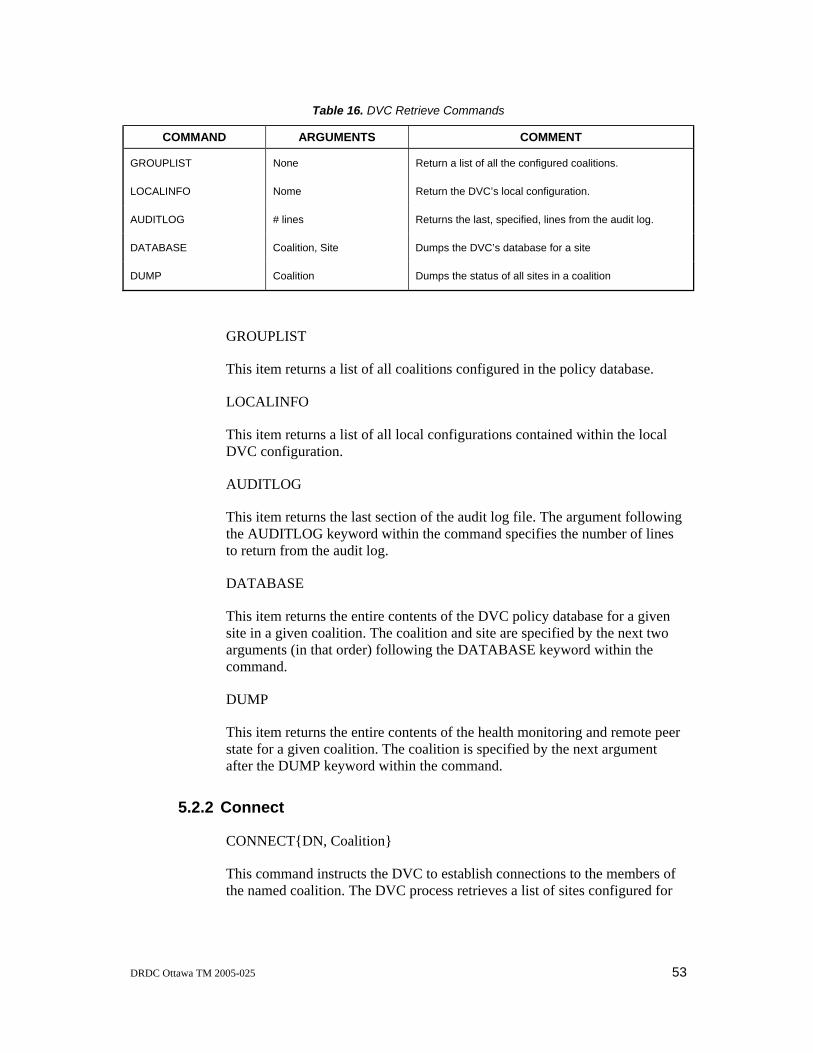
DRDC Ottawa TM 2005-025 53
Table 16. DVC Retrieve Commands
COMMAND ARGUMENTS COMMENT
GROUPLIST None Return a list of all the configured coalitions.
LOCALINFO Nome Return the DVC’s local configuration.
AUDITLOG # lines Returns the last, specified, lines from the audit log.
DATABASE Coalition, Site Dumps the DVC’s database for a site
DUMP Coalition Dumps the status of all sites in a coalition
GROUPLIST
This item returns a list of all coalitions configured in the policy database.
LOCALINFO
This item returns a list of all local configurations contained within the local DVC configuration.
AUDITLOG
This item returns the last section of the audit log file. The argument following the AUDITLOG keyword within the command specifies the number of lines to return from the audit log.
DATABASE
This item returns the entire contents of the DVC policy database for a given site in a given coalition. The coalition and site are specified by the next two arguments (in that order) following the DATABASE keyword within the command.
DUMP
This item returns the entire contents of the health monitoring and remote peer state for a given coalition. The coalition is specified by the next argument after the DUMP keyword within the command.
5.2.2 Connect
CONNECT{DN, Coalition}
This command instructs the DVC to establish connections to the members of the named coalition. The DVC process retrieves a list of sites configured for

54 DRDC Ottawa TM 2005-025
the coalition from the DVC policy database. For each site listed, if a VPN connection already exists, it skips to the next site. If a VPN connection does not exist, the DVC sends a policy proposal to that site based on the information in the DVC policy database.
The CONNECT command arguments include:
• the Distinguished Name of the DVC operator issuing the command, and
• the name of the Coalition to connect.
5.2.3 SConnect
SCONNECT{DN, Coalition, Site}
When the DVC process receives this command, it retrieves the policy configuration for the site from the policy database and sends a policy proposal based on the information in the policy database to the named coalition site.
The SCONNECT command arguments include the following:
• the Distinguished Name of the DVC operator issuing the command,
• the name of the Coalition which contains the site to connect, and
• the name of the Site to connect.
5.2.4 Delete
DELETE{DN, Coalition}
The DVC process retrieves the list of sites configured for the named coalition from the DVC policy database and sends a Delete message to each remote site in the list. The DVC subsequently refuses all DVC control sessions from all remote peers in the coalition until the site or the coalition is enabled.
The DELETE command arguments include the following:
• the Distinguished Name of the DVC operator issuing the command, and
• the name of the Coalition to disconnect.

DRDC Ottawa TM 2005-025 55
5.2.5 SDelete
SDELETE{DN, Coalition, Site}
The DVC process sends a Delete message to the specified site in the named coalition. The DVC then refuses all DVC control sessions from the remote site until the site is enabled.
The SDELETE command arguments include the following:
• the Distinguished Name of the DVC operator issuing the command,
• the name of the Coalition which contains the site to disconnect, and
• the name of the Site to disconnect.
5.2.6 Enable
ENABLE{DN, Coalition}
After receiving this command, the DVC process accepts future DVC control sessions from all remote sites in the named coalition.
The ENABLE command arguments include the following:
• the Distinguished Name of the DVC operator issuing the command, and
• the name of the Coalition to enable.
5.2.7 SEnable
SENABLE {DN, Coalition, Site}
After receiving this command, the DVC process accepts future DVC control sessions from the specified site in the named coalition.
The SENABLE command arguments include the following:
• the Distinguished Name of the DVC operator issuing the command,
• the name of the Coalition which contains the site to enable, and
• the name of the Site to enable.

56 DRDC Ottawa TM 2005-025
5.2.8 DATA
DATA{…}
This command is used to return data, or indicate status, from the DVC process to the DVC Management Console.
The DATA command’s arguments include the data or response to be returned to the DVC Management Console.
DRDC Ottawa TM 2005-025 57
6. The DVC Policy Editor
6.1 Overview
The DVC Policy Editor [6] facilitates the specification and compilation of DVC policies. These policies define which local networks require access to the remote coalition member site via the VPN, which local services are offered to the remote coalition member site, and which DNS name bindings are needed by the remote coalition member site to make use of the offered services. The policies also identify which services a remote coalition member must provide and which services a remote coalition member must not provide. Only the presence or absence of these services is considered, not specifically how the remote member site provides the services.
A DVC policy is encoded using XML and stored in a local disk file. The DVC Policy Editor facilitates the compilation of DVC policies by requiring that objects representing local resources such as networks, name spaces (domains), services, servers, and permitted traffic be defined once and subsequently referenced within site level policies. This eliminates many of the problems associated with erroneous data entry.
Once a DVC policy is compiled, it must be pushed to a local DVC Enforcement Point, which in the current system is the DVC system. The DVC Policy Editor converts the policy from the XML encoded format used by the Policy Editor to the XML encoded format required by the DVC. The policy is transmitted to the DVC enforcement point using a secure, mutually authenticated communication channel based on SSL.
The DVC Policy Editor application is not co-located with the DVC system itself, but rather runs on a separate system residing in the private network protected by the DVC. The DVC Policy Editor serves as the policy management centre, while the DVC serves as the policy negotiation and enforcement point.
6.2 DVC Policy Files
The DVC Policy Editor uses two XML encoded documents:
• a DVC Policy Specification File, and
• a DVC Policy Configuration File.
The DVC Policy Specification File contains an abstract specification of the DVC policy. Resources are defined once and referenced as required within the policy.
The DVC Policy Configuration File contains the policy specification in a system processable format that the DVC system can use.

58 DRDC Ottawa TM 2005-025
When a DVC security officer creates, loads, saves, or modifies a DVC policy, he is manipulating the DVC Policy Specification File. When the DVC security officer is ready to push a policy to the DVC system, the DVC Policy Editor converts the DVC Policy Specification File to a DVC Policy Configuration File and transmits it, as a single XML document, to the DVC over a mutually authenticated SSL connection. The DVC Policy Editor expands the references in the DVC Policy Specification File to create the DVC Policy Configuration File.
6.2.1 DVC Policy Specification File
The DVC Policy Specification File contains two logical data types: local object definitions and policy definition. The local objects describe local resources, such as domains, networks, and servers. These objects are referenced by the site level policies. Alternatively, local objects can be created as required when defining site level policies within a coalition definition. Figure 22 illustrates the XML schema design view of the entire DVC Policy Specification File. Annex F shows an example of an XML Policy Specification File and Annex G shows the corresponding XML schema for the Policy Specification File.

DRDC Ottawa TM 2005-025 59
Figure 22. DVC Policy Editor Object File
Table 17 lists the DVC objects and a description of their roles.
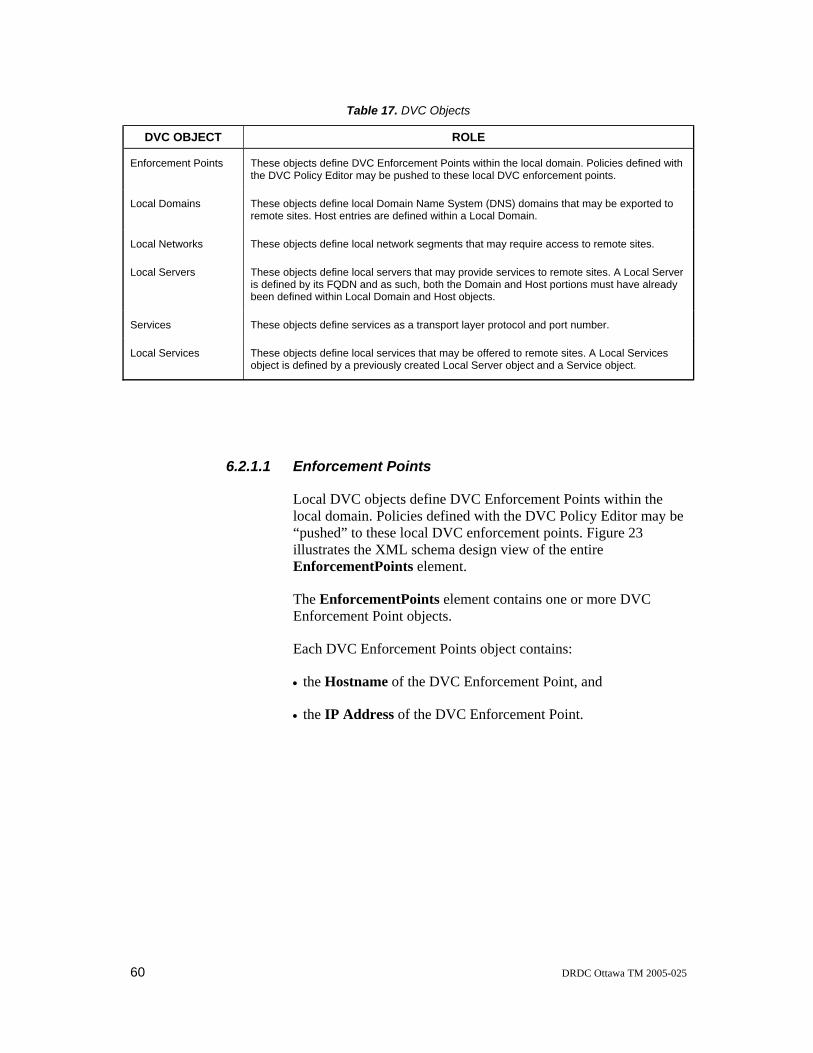
60 DRDC Ottawa TM 2005-025
Table 17. DVC Objects
DVC OBJECT ROLE
Enforcement Points These objects define DVC Enforcement Points within the local domain. Policies defined with the DVC Policy Editor may be pushed to these local DVC enforcement points.
Local Domains These objects define local Domain Name System (DNS) domains that may be exported to remote sites. Host entries are defined within a Local Domain.
Local Networks These objects define local network segments that may require access to remote sites.
Local Servers These objects define local servers that may provide services to remote sites. A Local Server is defined by its FQDN and as such, both the Domain and Host portions must have already been defined within Local Domain and Host objects.
Services These objects define services as a transport layer protocol and port number.
Local Services These objects define local services that may be offered to remote sites. A Local Services object is defined by a previously created Local Server object and a Service object.
6.2.1.1 Enforcement Points
Local DVC objects define DVC Enforcement Points within the local domain. Policies defined with the DVC Policy Editor may be “pushed” to these local DVC enforcement points. Figure 23 illustrates the XML schema design view of the entire EnforcementPoints element.
The EnforcementPoints element contains one or more DVC Enforcement Point objects.
Each DVC Enforcement Points object contains:
• the Hostname of the DVC Enforcement Point, and
• the IP Address of the DVC Enforcement Point.

DRDC Ottawa TM 2005-025 61
Figure 23. Enforcement Points
6.2.1.2 Local Networks
Local Network objects, which define local network segments that may require access to remote sites, are referenced by site level policies. Figure 24 illustrates the XML schema design view of the entire LocalNetworks element.
The LocalNetworks element contains one or more IP Network address objects.
Each IP Network address element contains:
• an attribute containing the Network Name,
• the IP Address for the network, and
• the IP Netmask for the network.

62 DRDC Ottawa TM 2005-025
Figure 24. Local Networks
6.2.1.3 Services
Service objects, which define services as a transport layer protocol and port number, are referenced by Local Server objects as well as site level policies. Figure 25 illustrates the XML schema design view of the entire Services element.
The Services element contains one or more Service objects.
Each Service element contains:
• an attribute containing the Service Name, and
• a Protocol element.
The Protocol element contains:
• an attribute containing the Protocol name or number, and
• the Port.

DRDC Ottawa TM 2005-025 63
Figure 25. Services
6.2.1.4 Local Domains
Local Domain objects define local DNS domains that may be exported to remote sites. Host entries are subsequently defined within a local domain. Local Domain objects and Host objects are referenced by Local Server objects. Figure 26 illustrates the XML schema design view of the entire LocalDomains element.
The LocalDomains element contains one or more Zone elements.
Each Zone element contains:
• an attribute containing the Domain name,
• the Mail Exchanger element, and
• one or more Host elements.
The MX element contains:
• an attribute containing the hostname of the Mail Exchanger, and
• the IP Address of the Mail Exchanger.
Each Host element contains:
• an attribute containing the name of the Host.

64 DRDC Ottawa TM 2005-025
• the Hostname for the host.
• the IP Address of the host.
Figure 26. Local Domains
6.2.1.5 Local Servers
Local Server objects define local servers that may provide services to remote sites. A Local Server is defined by its FQDN and, as such, both the Domain and Host portions must have already been defined within Local Domain and Host objects. Local Server objects are referenced by Permitted Traffic objects. When a Permitted Traffic object is included in a site level policy, the DNS information associated with the referenced Local Server object is automatically exported to the remote site. Figure 27 illustrates the XML schema design view of the entire LocalServers element.
The LocalServers element contains one or more IP Server objects.
Each IPServer element contains:
• an attribute containing the Server Name,
• a reference to a Host object, and
• a reference to a Domain object.

DRDC Ottawa TM 2005-025 65
Figure 27. Local Servers
6.2.1.6 Local Services
Local Services objects define local services that may be offered to remote sites. A Local Services object, defined by a previously created Local Server object and Service object, is referenced by site level policies. Figure 28 illustrates the XML schema design view of the entire LocalServices element.
The LocalServices element contains one or more Exported Service objects.
Each ExportedService element contains:
• an attribute containing the ExportedService Name,
• a reference to a Server Name object, and
• a reference to a Service Name object.
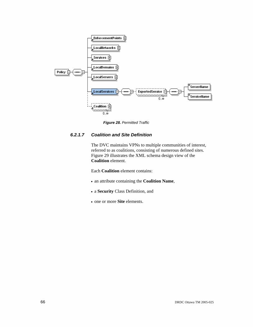
66 DRDC Ottawa TM 2005-025
Figure 28. Permitted Traffic
6.2.1.7 Coalition and Site Definition
The DVC maintains VPNs to multiple communities of interest, referred to as coalitions, consisting of numerous defined sites. Figure 29 illustrates the XML schema design view of the Coalition element.
Each Coalition element contains:
• an attribute containing the Coalition Name,
• a Security Class Definition, and
• one or more Site elements.

DRDC Ottawa TM 2005-025 67
Figure 29. Coalition Specification
Figure 30 illustrates the XML schema design view of the Site element.
Each Site element contains:
• an attribute containing the Site Name,
• a Remote policy definition, and
• a Local policy definition.

68 DRDC Ottawa TM 2005-025
Figure 30. Site Specification
6.2.1.8 Remote Policy Definition
The Remote Policy definition specifies the remote components of the policy. The elements identify the services that the remote site must provide as well as the services the remote site must not provide. Figure 31 illustrates the XML schema design view of the entire Remote element.
The Remote element contains:
• the Hostname of the remote DVC.
• the IPv4 and/or IPv6 Address of the remote DVC.
• the Services that the remote DVC Must provide.
• the Services that the remote DVC Must Not provide.
The Must element contains one or more references to a Service Name object.
The Must Not element contains one ore more references to a Service Name object.

DRDC Ottawa TM 2005-025 69
Figure 31. Remote Policy Specification
6.2.1.9 Local Policy Definition
The local policy definition specifies the local components of the policy. These elements refer to the local networks that require access to remote services and local services that can be offered to remote sites. Figure 32 illustrates the XML schema design view of the entire Local element.
The Local element contains:
• the Networks elements.
• the Traffic elements.
The Networks element contains one or more references to a Network Name object.
The Traffic element contains one or more references to a Local Service Name objects.

70 DRDC Ottawa TM 2005-025
Figure 32. Local Policy Specification
6.2.2 DVC Policy Configuration File
The DVC Policy Configuration File, which is used by the DVC system to import security policy information, contains the local security policy for each site defined in each coalition. Figure 33 illustrates the XML schema design view of the entire DVC Policy Configuration File. Annex H shows an example of an XML Policy Configuration File and Annex I shows the corresponding XML schema for the Policy Configuration File.

DRDC Ottawa TM 2005-025 71
Figure 33. DVC Policy Configuration File
6.2.2.1 Coalition and Site Definition
The DVC maintains VPNs to multiple communities of interest, referred to as coalitions, consisting of numerous defined sites. Figure 34 illustrates the XML schema design view of the Coalition element.
Each Coalition element contains:
• an attribute containing the Coalition Name,
• a Security class definition, and
• one or more Site elements.
Figure 34. DVC Policy - Coalition

72 DRDC Ottawa TM 2005-025
Figure 35 illustrates the XML schema design view of the Site element.
Each Site element contains:
• an Attribute containing the Site Name,
• a Remote Policy definition, and
• a Local Policy definition.
Figure 35. DVC Policy - Site
6.2.2.2 Remote Policy Definition
The remote policy definition specifies the remote components of the policy. These elements refer to the local DVC’s expectation of the remote DVC’s policy. Figure 36 illustrates the XML schema design view of the entire Remote element.
Figure 36. DVC Policy - Remote Policy
The Remote element contains:
• the Hostname of the remote DVC,

DRDC Ottawa TM 2005-025 73
• an IPv4 and/or IPv6 Address of the remote DVC, and
• the expected Traffic definition.
The Traffic element contains:
• the services that the remote DVC Must provide, and
• the services that the remote DVC Must Not provide.
The Must element contains one or more Protocol elements.
The Must Not element contains one or more Protocol elements.
Each Protocol element contains:
• an attribute containing the Protocol name or number, and
• the Port element.
6.2.2.3 Local Policy Definition
The local policy definition specifies the local components of the policy. These elements refer to the local DVC’s services that will be exported to the remote site. Figure 37 illustrates the XML schema design view of the entire Local element.
The Local element contains:
• the Networks elements,
• the DNS elements, and
• the Traffic elements.
The Networks element contains one or more Network elements.
The Network element contains:
• an attribute containing the Network IP Address, and
• the IP Netmask of the network.
The DNS element contains one or more Zone elements.
Each Zone element contains:
• an attribute containing the Domain name,

74 DRDC Ottawa TM 2005-025
• the Mail Exchanger element, and
• one or more Host elements.
The MX element contains:
• an attribute containing the Hostname of the Mail Exchanger, and
• the IP Address of the Mail Exchanger.
Each Host element contains:
• an attribute containing the Hostname.
• the IP Address of the host.
The Traffic element contains one or more Server elements.
Each Server element contains:
• the IP Address of the server, and
• a Protocol definition.
The Protocol element contains:
• an attribute containing the Protocol name or number, and
• the Port definition.
Figure 37. DVC Policy - Local Policy
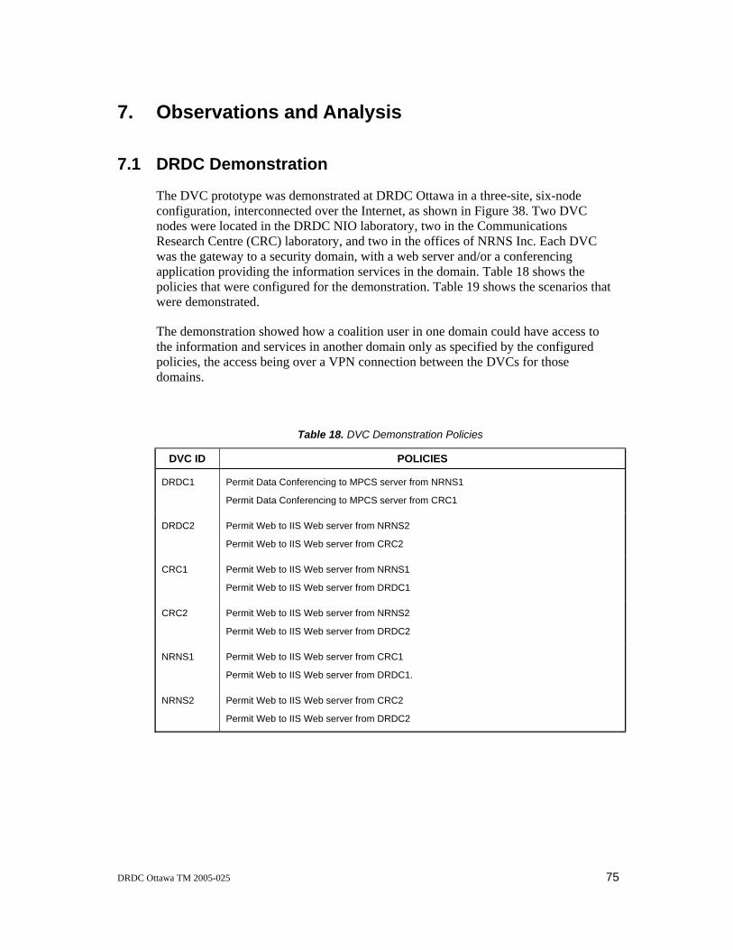
DRDC Ottawa TM 2005-025 75
7. Observations and Analysis
7.1 DRDC Demonstration
The DVC prototype was demonstrated at DRDC Ottawa in a three-site, six-node configuration, interconnected over the Internet, as shown in Figure 38. Two DVC nodes were located in the DRDC NIO laboratory, two in the Communications Research Centre (CRC) laboratory, and two in the offices of NRNS Inc. Each DVC was the gateway to a security domain, with a web server and/or a conferencing application providing the information services in the domain. Table 18 shows the policies that were configured for the demonstration. Table 19 shows the scenarios that were demonstrated.
The demonstration showed how a coalition user in one domain could have access to the information and services in another domain only as specified by the configured policies, the access being over a VPN connection between the DVCs for those domains.
Table 18. DVC Demonstration Policies
DVC ID POLICIES
DRDC1 Permit Data Conferencing to MPCS server from NRNS1
Permit Data Conferencing to MPCS server from CRC1
DRDC2 Permit Web to IIS Web server from NRNS2
Permit Web to IIS Web server from CRC2
CRC1 Permit Web to IIS Web server from NRNS1
Permit Web to IIS Web server from DRDC1
CRC2 Permit Web to IIS Web server from NRNS2
Permit Web to IIS Web server from DRDC2
NRNS1 Permit Web to IIS Web server from CRC1
Permit Web to IIS Web server from DRDC1.
NRNS2 Permit Web to IIS Web server from CRC2
Permit Web to IIS Web server from DRDC2

76 DRDC Ottawa TM 2005-025
NRNS1
NRNS2
DRDC1DRDC2
CRC1
Windows NTNetscape BrowserNetmeeting
LinuxApache Web ServerNetscape Browser
Windows NTMeeting Point Conference Server
Windows NTNetscape BrowserNetmeeting
CRC2
Windows 2000IIS Web ServerNetscape Browser
Windows 2000IIS Web ServerNetscape Browser
LinuxApache Web ServerNetscape Browser
Windows NTIIS Web ServerNetscape Browser
Windows NTNetscape BrowserNetmeeting
Figure 38. DVC Demonstration Configuration
Table 19. DVC Demonstration Scenarios
DVC ID SCENARIO DESCRIPTION
All Demo Coalition is fully meshed to start (all VPN connections green in management display)
From DRDC1 Connect to DRDC2 web server - www.privateb.drdc-rddc.gc.ca - fails
From DRDC1 Disconnect the NRNS1 site. DRDC1 shows the NRNS1 site down. DRDC2 shows loss of connectivity between DRDC 1 and NRNS1.
From DRDC1 Connect to the NRNS1 web server - www.privatea.nrns.ca - fails
From DRDC1 Connect the NRNS1 site. DRDC1 shows the NRNS1 site up. DRDC2 shows a connection between DRDC1 and NRNS1.
From DRDC1 Connect to the NRNS1 web server - www.privatea.nrns.ca - success

DRDC Ottawa TM 2005-025 77
From DRDC1 Connect to the DRDC1 MPCS server – mpcs.privatea.drdc-rddc.gc.ca - success
From NRNS1 Connect to the DRDC1 MPCS server – mpcs.privatea.drdc-rddc.gc.ca - success
From DRDC 1 Disconnect from the Demo Coalition
7.2 International Demonstrations
The DVC prototype has been demonstrated internationally, over the Internet, with nodes at DRDC, University College London (UCL) and the University of Murcia (UMU) in Spain. UCL has also demonstrated the DVC prototype over the 6NET (see Section 7.3.3).
7.3 Related Projects
Concurrent with the development and testing of the DVC prototype, a number of other projects, briefly described in the following subsections, were also investigating the use of VPN technology for secure information interchange.
7.3.1 INSC
Section 2.5 has already introduced the INSC project, which uses IPsec security gateways to separate security domains. The main security gateway used in the INSC network was a FreeS/WAN IPsec implementation on a Linux system, modified to support IPv6.The FreeS/WAN IKE daemon, Pluto, provided dynamic key establishment for IPsec security associations. The INSC security gateways used X.509 authentication to establish VPN connections but the key management was largely handled by manual procedures and out-of-band exchange mechanisms. Furthermore, the INSC security gateways did not support the use of security policies to control access to the services in the domains protected by the gateways. The INSC network infrastructure also included DNS, routing, and filters. These systems were configured and managed separately from the security gateways, and much of the configuration information for these systems was distributed using out-of-band mechanisms.
Using the DVC prototype as the security gateway in the INSC infrastructure would permit centralized management and configuration and the negotiation of security policies. This would allow for secure, authenticated configuration of all network devices and reduce the occurrence of configuration errors.

78 DRDC Ottawa TM 2005-025
7.3.2 University of Murcia
The University of Murcia (UMU) is currently developing two prototype systems of interest to the DVC project: a public key infrastructure (PKI) system that runs over an IPv6 network (UMU-PKIv6) and a Policy Based Network Management (PBNM) system (UMU-PBNM).
7.3.2.1 UMU-PKIv6
The PKIX-CMC client could extend support for certificate lifecycle management to the DVC system. Ideally, the PKIX-CMC client should be incorporated into the DVC software, but since the DVC software is written in Perl and the PKIX-CMC client is written in Java, the integration might not be straightforward. An alternate approach may be to separate the certificate lifecycle management from the DVC software in a standalone Java application that updates the appropriate key and certificate files as required.
The enhanced UMU-PKIv6 could extend support for inter-domain trust relationships to the DVC system. The DVC system would have the ability to validate a certificate issued from a third party certification authority. The Simple Certificate Validation Protocol (SCVP) client should be incorporated into the DVC software, but since the DVC software is written in Perl and the PKIX-CMC client is written in Java, the integration may not be straightforward. An alternate approach may be to create a simple socket based interface between the Perl based DVC software and the Java based SCVP proxy server that incorporates the SCVP client.
7.3.2.2 UMU-PBNM
The DVC and UMU-PBNM systems provide similar capabilities in two specific areas. Both systems provide a policy specification mechanism and both systems dynamically configure subsystems and/or devices to enforce the specified policies.
The DVC system could be combined with the UMU-PBNM system to define, negotiate, enforce, and monitor a complete network security policy. This would allow the UMU system to use the DVC’s policy negotiation mechanism, and the DVC system to use the UMU-PBNM’s support for diverse network devices.

DRDC Ottawa TM 2005-025 79
7.3.3 6NET Experiments
6NET [7] is a three-year European project to investigate and demonstrate the use of IPv6 technology. The project has built a native IPv6-based network connecting sixteen countries to gain experience in IPv6 deployment and migration from existing IPv4-based networks. The network is being used to test a variety of new IPv6 services and applications as well as interoperability with legacy applications.
The University College London (UCL) Network and Multimedia Research Group have produced a report for the 6NET project that discusses IPv6-enabled dynamic VPN technology [8], including the DVC system. The DVC project team reviewed the report and provided comments to UCL. As mentioned in Section 7.2, UCL has also demonstrated the DVC over the 6NET.

80 DRDC Ottawa TM 2005-025
8. Conclusions
8.1 Summary
The DVC project has successfully demonstrated a prototype solution for the rapid deployment and self-configuration of VPN connections that provides a secure information exchange capability in a dynamic coalition environment. The solution provides interoperability because it is based on IPsec, a standardized network security protocol, and it operates over both IPv4 and IPv6 networks. Because security is provided at the network layer, the solution is application independent and can be used to secure any application services that operate over an IP network. Furthermore, the use of policy negotiation for each point-to-point VPN connection provides the capability to provide different application services securely according to different security policies over each VPN connection. Finally, dynamic self-configuration provides the flexibility to allow the network configuration to adapt to continually changing circumstances, as is the case for most coalition environments.
The development of the DVC capability supports the strategic C4ISR goal of an enhanced capability for secure information interchange for military operations. However, the current DVC prototype does not provide a high assurance security capability because it is implemented using open source software and software encryption on a commercial platform. Nevertheless, it does demonstrate a viable capability and, if implemented in a more secure manner with an evaluated encryption engine, it could provide a low-to-medium assurance solution to enforce need-to-know separation over a protected network.
8.2 Further Research
The DVC prototype is a promising technology that continues to evolve. DRDC has now expanded the scope of the DVC project to explore the integration of the DVC prototype with a policy-based network management (PBNM) tool prototype developed by the UMU. A second generation DVC system will focus exclusively on inter-domain policy negotiation and will divest its responsibilities for configuring PEPs to the UMU-PBNM system. The UMU-PBNM system makes use of standards based protocols such as the Common Open Policy Service (COPS) that facilitate the dynamic configuration of network and security devices. COPS also removes the requirement to have the PEP co-located with the DVC.
The inter-domain security policies defined for the first generation DVC prototype are simplistic and do not conform to any specific standard. The second generation DVC prototype will redefine the inter-domain security policies using standards such as the Common Information Model (CIM). These second generation inter-domain security policies will include time-of-day constraints, conditional statements, and other information that will assist in the evaluation of these policies. The enhanced inter-

DRDC Ottawa TM 2005-025 81
domain security policies will permit policy to be described using high-level terms instead of device-level configuration items.
Ultimately, the DVC prototype should be able to support the requirements of truly dynamic VPNs, as specified in Section 2.6. However as, Table 1 shows, the current prototype still lacks many important and desirable capabilities, particularly the capability of dynamic discovery to find other coalition devices present on the network. Currently, the network location of a remote partner must be known in advance since the partner’s network identity is included in the local inter-domain security policies. Ideally, a DVC device should be able to connect to the network at any attachment point and dynamically discover other coalition devices present on the network. The need for dynamic discovery is also recognized by NATO where dynamic discovery mechanisms are being studied in the second phase of the Interoperable Networks for Secure Communications project (INSC-II). The extension of the DVC prototype to include a dynamic discovery mechanism is an additional future research goal, as are extensions to address the other requirements in Table 1 that are unmet at present.

82 DRDC Ottawa TM 2005-025
9. References
1. RFC 2401, Security architecture for the Internet Protocol, November 1998
2. Interoperable Networks for Secure Communications Symposium, November 4-6, 2003.
3. INSC Final Report, INSC/Task1/D011, March 2004-09-10
4. Touch, J., and Hotz, S., The X-Bone, USC/Information Sciences Institute, November 1998, available at http://www.isi.edu/touch/pubs/gi98/
5. The Dynamic VPN Controller (DVC) Demonstrator Installation, Configuration and Operations Manual, Version 1.4, Section 6.1, NRNS Incorporated, Report 005-02-003.6-04, April 2004
6. The Dynamic VPN Controller (DVC) Demonstrator Policy Editor User Manual Version 1.2, NRNS Incorporated, Report 005-02-003.9-0, April 2004.
7. http://www.6net.org
8. D4.3.1, First set of IPv6-enabled Dynamic VPNs Running, 6NET, IST-2001-32603, March 28, 2003, available at http://www.6net.org/publications/deliverables/D4.3.1.pdf

DRDC Ottawa TM 2005-025 83
Annex A: DVC Software The DVC software is provided as a modified FreeBSD distribution that includes the complete DVC system. The DVC system is installed as a turnkey system on an Intel-based PC by following the installation procedure in Annex C. This procedure takes approximately 15 minutes to complete. After installing the DVC software, the DVC system is configured using the DVC configuration script, described in Annex D, which takes about 10 minutes. The configuration script will establish the DVC private CA, generate the necessary keys, certificate signing requests and certificates, as well as configure all aspects of the DVC system. The DVC system is implemented on a single FreeBSD-4.6 system that includes the software components listed in Table 20.
Table 20. Software Components
SOFTWARE COMMENT
FreeBSD-4.6 (Kernel Developer) Base operating system.
Perl [5.8.0]
(This is a newer version than that included with FreeBSD-4.6)
Code Interpreter
OpenSSL (version 0.9.7d)
(This is a newer version than that included with FreeBSD-4.6)
Certificate issuance and management. SSL secured connections for DVC control.
KAME (Included with FreeBSD-4.6) IPsec Subsystem. Network layer security.
IP Filter [3.4.33pre2]
(This is a newer version than that included with FreeBSD-4.6)
Firewall Subsystem. Packet filtering for access control.
Bind (9.2.2)
(This is a newer version than that included with FreeBSD-4.6)
Domain Name System (DNS) Subsystem. Name resolution.
Zebra (0.93b) Routing Subsystem. Dynamic routing of remote networks.
XB_Defs.pl (1.83)
XB_LOGS.pl (1.14)
XB_SSL.pl (1.12)
XB_Utils.pl (1.17)
X-bone Perl modules to facilitate SSL control sessions.

84 DRDC Ottawa TM 2005-025
SSLeay.pm (1.25) Perl module. Perl interface to OpenSSL.
Netmask.pm (1.9002) Perl module. Network mask functions.
Apache (2.0.49) Web server. DVC Operator interface.
XML::Schema (0.07)
XML::Parser (2.33)
XML::Writer (0.4)
XML::Writer::String (0.1)
Expat (1.95.6)
XML parsers and writers. XML:Schema was developed by Canon Research Centre Europe Ltd.
Libpng (1.2.2)
libjpeg (6b)
zlib (1.1.4)
gdlib (2.0.15)
gd.pm (2.0.6)
patch (2.5)
Graphics libraries and Perl modules for building coalition network maps.
Net::Telnet (3.03)
Net::Telnet::Cisco (1.10)
Interface between the DVC System and Zebra.
Net::IP (1.20) IPv4 and IPv6 Perl IP utility functions.
INET6 (1.28)
Socket6 (0.12)
IPv6 INET Socket support.
Tcpdump (3.7.2)
(This is a newer version than that included with FreeBSD-4.6)
Packet Capture Utility
OpenSSH (3.8p1)
(This is a newer version than that included with FreeBSD-4.6)
Secures management sessions to DVC system.

DRDC Ottawa TM 2005-025 85
Annex B: DVC Configuration Files
The DVC prototype demonstrator configuration is controlled by three files described in this Annex.
The DVC Configuration File
The DVC configuration file (dvc.conf) contains the configuration parameters required to operate the DVC. All parameter values are determined by the DVC configuration script shown in Annex D. An example of a DVC configuration file is shown below.
Hostname = dvc1.nrns.ca Ext Address = 216.191.212.232 Ext6 Address = 2001:410:401:104::111 Int Address = 10.10.1.1 Int6 Address = fec0:ffff:1::1 IPv4 Router = 216.191.212.225 IPv6 Router = 2001:410:401:104::101 Int Iface = xl1 Ext Iface = xl0 ca cert = /usr/local/dvc/certs/ca/Cacert local cert = /usr/local/dvc/certs/certs/dvc1.nrns.ca.crt local key = /usr/local/dvc/certs/private/dvc1.nrns.ca.key admin ca cert = /usr/local/dvc/certs/ca/local.cacert admin local cert = /usr/local/dvc/certs/certs/host1.private.nrns.ca.crt admin local key = /usr/local/dvc/certs/private/host1.private.nrns.ca.key
A description of each configuration parameter follows. Keywords, tags, and sample values appear as bold text.
Hostname = dvc1.nrns.ca
This parameter defines the external hostname of the DVC. The value is the FQDN to which the external IP address maps in the DNS. The hostname must appear as the common name (CN) in the DVC’s X.509 certificate.
Ext address = 216.191.212.232
This parameter defines the external IPv4 address of the DVC. The value is the IPv4 address of the external network interface. This item is optional and is only required if the DVC supports IPv4.
Ext6 Address = 2001:410:401:104::111

86 DRDC Ottawa TM 2005-025
This parameter defines the external IPv6 address of the DVC. The value is the IPv6 address of the external network interface. This item is optional and is only required if the DVC supports IPv6.
Int address = 10.10.1.1
This parameter defines the internal IPv4 address of the DVC. The value is the IPv4 address of the internal network interface. This is the source and destination IPv4 address for health monitoring packets. This item is optional and is only required if the DVC supports IPv4.
Int6 Address = fec0:ffff:1::1
This parameter defines the internal IPv6 address of the DVC. The value is the IPv6 address of the internal network interface. This is the source and destination IPv6 address for health monitoring packets. This item is optional and is only required if the DVC supports IPv6.
IPv4 Router = 216.191.212.225
This parameter defines the IPv4 address of the default router for the DVC. This item is optional and is only required if the DVC supports IPv4.
IPv6 Router = 2001:410:401:104::101
This parameter defines the IPv6 address of the default router for the DVC. This item is optional and is only required if the DVC supports IPv6.
Int iface = xl1
This parameter defines the internal network interface of the DVC. The value is the device name of the internal network interface.
Ext iface = xl0
This parameter defines the external network interface of the DVC. The value is the device name of the external network interface.
ca cert = /usr/local/dvc/certs/ca/Cacert
This parameter specifies the full pathname of the file that contains the public key certificate of the DVC project root CA. The value is always set to the path shown. The DVC project CA signs certificates issued to the DVC for authenticating to remote DVCs.
local cert = /usr/local/dvc/certs/certs/dvc1.nrns.ca.crt
This parameter specifies the full pathname of the file containing the public key certificate that the DVC uses to authenticate to remote DVCs. This file is always located in the /usr/local/dvc/certs/certs/ directory with the filename <Public FQDN>.crt.
local key = /usr/local/dvc/certs/private/dvc1.nrns.ca.key

DRDC Ottawa TM 2005-025 87
This parameter specifies the full pathname of the file containing the private key that the DVC uses to authenticate with other DVCs. This file is always located in the /usr/local/dvc/certs/private/ directory with the filename <Public FQDN>.key.
admin ca cert = /usr/local/dvc/certs/ca/local.cacert
This parameter specifies the full pathname of the file that contains the public key certificate of the DVC local root CA. The value is always set to the path shown. The DVC local root CA signs certificates issued to DVC operators, security officers, and to the local DVC, for mutual authentication.
admin local cert = /usr/local/dvc/certs/certs/host1.private.nrns.ca.crt
This parameter defines the full pathname of the file containing the public key certificate for authenticating the DVC to the local operators and security officers. This file is always located in the /usr/local/dvc/certs/certs/ directory with the filename <Private FQDN>.crt.
admin local key = /usr/local/dvc/certs/private/host1.private.nrns.ca.key
This parameter defines the location of the file containing the private key for authenticating the DVC to the DVC operators and security officers. This file is always located in the /usr/local/dvc/certs/private/ directory with the filename of <Private FQDN>.crt.
The DVC Policy Configuration File
The DVC Policy Configuration File (policy.xml), described in Section 6.2.2, contains the XML encoded security policies established for configured coalitions and coalition member sites. The DVC Policy Editor is used to compile the DVC Policy Configuration File from the DVC Policy Specification File, as described in Section 6. Examples of a Policy Specification File and a Policy Configuration File are shown in Annex F and Annex H, respectively.
Once a DVC Policy Configuration File has been compiled, it must be pushed to a local DVC enforcement point. The policy is transmitted to the DVC enforcement point using an authenticated SSL communication channel. The SSL session, which connects to the DVC on TCP port 2001, is mutually authenticated using X.509 certificates.
The DVC Security Class File
The DVC security class file (dvc.security) defines security classes that correspond to pre-defined sets of IPsec parameters. It is assumed that the DVC security classes are defined in advance and are well known to coalition member sites. It is also assumed that only a few security classes need to be defined. When a class is defined, its settings should not be altered. If the security parameters in a security class need to be altered, a new security class should be created instead. An example of a DVC security class file is shown below.
[Class A] Phase 1 encryption algorithm = 3DES-CBC

88 DRDC Ottawa TM 2005-025
Phase 2 AUTHENTICATION_ALGORITHM = HMAC-SHA1
A description of each configuration setting follows. Keywords, tags, and sample settings appear as bold text.
[Class A]
This tag defines the security class name. This name is used to reference a security class from within the DVC policy configuration.
Phase 1 encryption algorithm = 3DES-CBC
This parameter defines the encryption algorithm used to secure the VPN. Table 11 lists the valid values for this setting.
Phase 2 AUTHENTICATION_ALGORITHM = HMAC-SHA1
This parameter defines the authentication algorithm used to authenticate the VPN. Table 12 lists the valid values for this setting.

DRDC Ottawa TM 2005-025 89
Annex C: DVC System Installation This annex describes the DVC system installation procedure. This procedure installs the DVC system software. 1. Download the DVC ISO image. 2. Create a CD from the ISO image. 3. Boot from the CD or create the two boot disks using the fdimage.exe program located in
\tools on the CD. The boot disk images are located in /floppies on the CD. Create kern.flp and mfsroot.flp, Kern.flp is the boot disk. Change the floppy to mfsroot.flp when prompted. There have been problems with the installation when booting from CD.
4. Press ENTER to boot immediately. 5. Once you reach the Kernel configuration selection screen: Skip Kernel Configuration and
continue with installation. 6. Select Standard. 7. To “use fdisk” select OK. 8. Use the arrow keys to position the highlighted bar over each partition and press D to
delete the slices. 9. Press A to use the entire disk. 10. Press Q to exit fdisk. 11. Select Standard for boot manager. 12. Select OK to configure partitions. 13. Create the following Partitions by pressing C to create a partition:
/ fs 100MB swap 512MB /usr fs (rest of the drive)
14. Press Q to quit. 15. Select custom. 16. Select BIN. 17. Select EXIT.

90 DRDC Ottawa TM 2005-025
18. Select EXIT. 19. Select Options. 20. Change the release name to DVC-#.#.#x. This is the same name as the DVC ISO image
file - without the ".iso" the extension. 21. Change the media to CDROM. 22. Q to quit. 23. Yes to commit. 24. Wait for distribution to be copied. 25. OK to continue. 26. Select No to Configure Ethernet. 27. Select Yes to Network Gateway. 28. Select NO to Configure Inetd. 29. Select NO to anonymous FTP access. 30. Select NO to NFS SERVER. 31. Select NO to NFS CLIENT. 32. Select NO to define a security policy. 33. Click OK. 34. Select NO to configure console. 35. Select YES to configure Timezone. 36. Select NO to UTC realtime clock. 37. Select Timezone 38. Confirm correct Timezone. 39. Select NO to LINUX Compatibility. 40. Select NO to non USB mouse.

DRDC Ottawa TM 2005-025 91
41. Select NO in response to the prompt "The FreeBSD package collection is a collection of thousands of ready-to-run applications, from text editors to games to WEB servers and more. Would you like to browse the collection now.".
42. Select YES to adding user accounts. 43. User account Info:
Login ID: dvc Group: wheel Password: <password> Set password. Full Name: DVC
44. OK. 45. Select EXIT. 46. Select OK to setting root Password: 47. Set and confirm root password. 48. Select NO to returning to configuration. 49. Select EXIT installation. 50. Select YES to confirm exit. 51. System will reboot. 52. Proceed to configure the DVC.

92 DRDC Ottawa TM 2005-025
Annex D: DVC System Configuration A system configuration script is provided with the DVC software distribution to configure the DVC system once it has been installed. The following explains how to use the configuration script. 1. Login as root. 2. Ensure that the time is correct. 3. Enter the command /usr/local/dvc/install/install.pl. 4. Configure for IPv4? (y/n)
This will determine if the DVC will support IPv4. If you select ‘n’ then you will not be prompted for IPv4 information.
5. Configure for IPv6? (y/n) This will determine if the DVC will support IPv6. If you select ‘n’ then you will not be prompted for IPv6 information.
6. Enter the EXTERNAL FQDN for the DVC: This will set the fully qualified domain name for the external interface. It should be set to the FQDN that the external address of the DVC will resolve to. (Example: dvc1.nrns.ca) This value should be a real FQDN.
7. Enter the External Interface for the DVC: This will set the external interface of the DVC. The interface must already exist on the system and be displayed when the ifconfig –a command is issued. The device selected must later be connected to the external network infrastructure. This should only be done after the final reboot. (Example: xl0)
8. Enter the IPv4 Address for this Interface: This will set the external IPv4 address of the DVC. This value should be set to an address which is available on the external network infrastructure. (Example: 216.191.212.232) This should be a real IP address from one of your Internet assigned network blocks.
9. Enter the IPv4 Netmask for this Interface:
This will set the external IPv4 netmask of the DVC. This value should be set to the netmask for the external network infrastructure. (Example: 255.255.255.0) This should be the real netmask for your external network Infrastructure.
10. Enter the IPv6 Address for this Interface:
This will set the external IPv6 address of the DVC. This value should be set to an address that is available on the external network infrastructure. (Example:

DRDC Ottawa TM 2005-025 93
2001:410:401:104::101) This should be a real IP address from one of your Internet assigned network blocks.
11. Enter the IPv6 Netmask for this Interface: This will set the external IPv6 netmask of the DVC. This value should be set to the netmask for the external network infrastructure. (Example: ffff:ffff:ffff:ffff::) This should be the real netmask for your external network infrastructure.
12. Enter the INTERNAL FQDN for the DVC: This will set the Fully Qualified Domain Name for the internal interface. This will also set the URL the operator will use to contact the DVC Management Console. (Example: host1.private.nrns.ca) This value can be a fake name.
13. Enter the Internal Interface for the DVC:
This will set the internal interface of the DVC. The interface must already exist on the system and be displayed when the ifconfig –a command is issued. The device selected must later be connected to the internal network infrastructure. This should only be done after the final reboot. (Example: xl1)
14. Enter the IPv4 Address for this Interface: This will set the Internal IPv4 address of the DVC. This value should be set to a private address which belongs to the private network infrastructure you intend to use behind the DVC. (Example: 10.10.1.1) This value SHOULD NOT be set to an Internet routable address, rather it should belong to one of the following networks 10.0.0.0/8, 172.16.0.0/12, or 192.168.0.0/16. Note: Private address space must be unique across a coalition. The DVC software
does not employ network address translation to resolve address conflicts. 15. Enter the IPv4 Netmask for this Interface.
This will set the internal IPv4 netmask of the DVC. This value should be set to the netmask for the internal private network infrastructure. (Example: 255.255.255.0) This should be the real netmask for your internal network infrastructure. Although any netmask value should work it is recommended that a class C (255.255.255.0) netmask be used on the internal interface. This will ensure that the default zone files for the internal network will be correct.
16. Enter a unique IPv4 Address to be used as the ospf router-id:
The Zebra routing daemon requires an IPv4 Address to be used as the ospf router-id even if IPv4 is not configured. Pick a unique IPv4 address to use as the ospf router-id. (Example: 10.10.1.1)
17. Enter the IPv6 Address for this Interface:
This will set the internal IPv6 address of the DVC. This value should be set to a private address, which belongs to the private network infrastructure you intend to use behind the DVC. (Example: fec0:ffff:1::1) This value SHOULD NOT be set to an Internet routable address, rather it should belong to the following network fec0::/10.
94 DRDC Ottawa TM 2005-025
Note: Private address space must be unique across a coalition. The DVC software does not employ network address translation to resolve address conflicts.
18. Enter the IPv6 Netmask for this Interface:
This will set the internal IPv4 netmask of the DVC. This value should be set to the netmask for the internal private network infrastructure. (Example: ffff:ffff:ffff:ffff::) This should be the real netmask for your internal network infrastructure.
19. Enter the IPv4 Default Router for the DVC: This will set the IPv4 address of the DVC’s Default Gateway. This value should be set to the default gateway for the external network infrastructure. The DVC’s default router must be on the External network Infrastructure.
20. Enter the IPv6 Default Router for the DVC: This will set the IPv6 address of the DVC’s Default Gateway. This value should be set to the default gateway for the external network Infrastructure. The DVC’s default router must be on the external network infrastructure.
21. Enter the OSPF cost. This will set the ospf cost for ospfd. This value should match the ospf cost on the network connected to the internal DVC interface.
22. Do you wish to configure an IPv4 NTP Server? (Y/N)
This will determine if the IPv4 filters are modified to allow NTP. If ‘y’ is selected then the IPv4 filters will be modified, and a crontab entry will be added to allow NTP synchronization. If ‘n’ is selected then filters will be configured to block NTP and no crontab entry will be added.
23. Enter the IP address of the NTP Server: This will set the IPv4 address of the NTP Server.
24. Do you wish to configure an IPv6 NTP server? (Y/N) This will determine if the IPv6 filters are modified to allow NTP. If ‘y’ is selected then the IPv6 filters will be modified, and a crontab entry will be added to allow NTP synchronization. If ‘n’ is selected then filters will be configured to block NTP and no crontab entry will be added. NOTE: In the DVC-0.0.3a Release this should be always set to ‘n’.
25. Enter the IP address of the NTP Server: This will set the IPv6 address of the NTP Server.
26. Enter the two letter country code. 27. Enter the State/Province. 28. Enter the Locality name.
DRDC Ottawa TM 2005-025 95
29. Enter the Organization name. 30. Enter a Common name for the Local Management ROOT CA. 31. Enter the Common name of the Operator. 32. Enter the Email address of the Operator.
33. Enter the PEM password & Verify.
This is the beginning or the creation of the DVC’s local CA. This CA will be used to sign the operator’s certificates as well as the certificate used by the Apache server and the certificate used by the DVC to authenticate to the DVC Policy Editor. Enter a password to protect the local CA’s keyfile. You will then be asked to verify the password.
34. Enter the PEM password. You must enter the PEM password a third time to unlock the local CA’s key file to be able to sign the CA’s certificate, which you are about to create. Enter the PEM password you selected in step 33.
35. Enter the PEM password.
You must enter the PEM password to unlock the local CA’s key file to be able to sign the Apache SSL certificate, which you just created. Enter the PEM password you selected in step 33.
36. Enter Y to sign the Certificate and Y to commit the changes. 37. Enter the PEM password.
You must enter the PEM password to unlock the CA’s key file to be able to sign the Operator’s certificate, which you just created. Enter the PEM password you selected in step 33.
38. Enter Y to sign the Certificate and Y to commit the changes. 39. Enter the Export Password.
This will set the export password on the .p12 PKCS#12 file that contains the operator’s certificate and private key. This file is used to import the certificate information into the browser. This password will protect the Operator’s PKCS#12 file. Enter a password then re-enter it to verify.
40. Enter & Verify the SSH private key password. 41. Insert a blank MSDOS-formatted diskette into the DVC’s diskette drive and press
ENTER. 42. When prompted that it is safe to remove the diskette, remove it. The disk will contain
four files, the first (private.key) is the SSH private key and should be placed in the user’s ~/.ssh or $HOME/.ssh directory on the management system and renamed to reflect the

96 DRDC Ottawa TM 2005-025
SSH configuration (id_rsa). The second file, which has the .p12 extension, is used to import the operator’s certificate and key information into the operator’s browser. The third file (.csr) is a certificate signature request file. This file should be e-mailed to [email protected] to be signed by the DVC Project CA. Once the certificate has been signed a .crt file will be returned to you. Copy the file back to this diskette (maintaining the filename which it was sent as) and return the diskette to the DVC’s diskette drive. The fourth file is the local DVC CA certificate (ca.crt) which can be imported into your DVC Policy Editor.
43. Press ENTER once the diskette has been returned to the drive. 44. Remove the diskette when prompted. 45. Reboot the DVC system.

DRDC Ottawa TM 2005-025 97
Annex E: DVC Commands XML Schema <xsd:schema xmlns:xsd="http://www.w3.org/2001/XMLSchema"> <xsd:element name="DVCCmd"> <xsd:complexType> <xsd:choice> <xsd:element ref="SSLCmd"/> <xsd:element ref="PIPECmd"/> </xsd:choice> </xsd:complexType> </xsd:element> <xsd:element name="PIPECmd"> <xsd:complexType> <xsd:choice> <xsd:element ref="CLOSE"/> <xsd:element ref="PINGREPLY"/> <xsd:element ref="LOCALERROR"/> </xsd:choice> </xsd:complexType> </xsd:element> <xsd:element name="PROPOSE"> <xsd:complexType> <xsd:sequence> <xsd:element ref="DN"/> <xsd:element ref="ID"/> <xsd:element ref="IPAddress" maxOccurs="2"/> <xsd:element ref="Local"/> <xsd:element ref="Security"/> </xsd:sequence> </xsd:complexType> </xsd:element> <xsd:element name="APROPOSE"> <xsd:complexType> <xsd:sequence> <xsd:element ref="DN"/> <xsd:element ref="ID"/> <xsd:element ref="IPAddress" maxOccurs="2"/> <xsd:element ref="Local"/> </xsd:sequence> </xsd:complexType> </xsd:element> <xsd:element name="ACCEPT"> <xsd:complexType> <xsd:sequence> <xsd:element ref="DN"/> <xsd:element ref="ID"/> <xsd:element ref="LocalSPI"/> <xsd:element ref="RemoteSPI"/> </xsd:sequence> </xsd:complexType> </xsd:element> <xsd:element name="DENY"> <xsd:complexType> <xsd:sequence> <xsd:element ref="DN"/> <xsd:element ref="ID"/> <xsd:element ref="Reason"/> </xsd:sequence> </xsd:complexType> </xsd:element>

98 DRDC Ottawa TM 2005-025
<xsd:element name="DELETE"> <xsd:complexType> <xsd:sequence> <xsd:element ref="DN"/> </xsd:sequence> </xsd:complexType> </xsd:element> <xsd:element name="STATUS"> <xsd:complexType> <xsd:sequence> <xsd:element ref="DN"/> <xsd:element ref="Site" maxOccurs="unbounded"/> </xsd:sequence> </xsd:complexType> </xsd:element> <xsd:element name="ERROR"> <xsd:complexType> <xsd:sequence> <xsd:element ref="DN"/> <xsd:element ref="Reason"/> </xsd:sequence> </xsd:complexType> </xsd:element> <xsd:element name="SSLCmd"> <xsd:complexType> <xsd:choice> <xsd:element ref="PROPOSE"/> <xsd:element ref="APROPOSE"/> <xsd:element ref="ACCEPT"/> <xsd:element ref="DENY"/> <xsd:element ref="DELETE"/> <xsd:element ref="STATUS"/> <xsd:element ref="ERROR"/> </xsd:choice> </xsd:complexType> </xsd:element> <xsd:element name="CLOSE"> <xsd:complexType> <xsd:sequence> <xsd:element ref="DN"/> <xsd:element ref="Reason"/> </xsd:sequence> </xsd:complexType> </xsd:element> <xsd:element name="PINGREPLY"> <xsd:complexType> <xsd:sequence> <xsd:element ref="Site"/> </xsd:sequence> </xsd:complexType> </xsd:element> <xsd:element name="LOCALERROR"> <xsd:complexType> <xsd:sequence> <xsd:element ref="DN"/> <xsd:element ref="Reason"/> </xsd:sequence> </xsd:complexType> </xsd:element> <xsd:element name="DN" type="FQDNType"/> <xsd:element name="ID" type="PolicyNumType"/> <xsd:element name="Local">

DRDC Ottawa TM 2005-025 99
<xsd:complexType> <xsd:sequence> <xsd:element ref="Networks" minOccurs="0"/> <xsd:element ref="DNS" minOccurs="0"/> <xsd:element ref="Traffic" minOccurs="0"/> </xsd:sequence> </xsd:complexType> </xsd:element> <xsd:element name="Networks"> <xsd:complexType> <xsd:sequence> <xsd:element ref="Network" maxOccurs="unbounded"/> </xsd:sequence> </xsd:complexType> </xsd:element> <xsd:element name="Protocol"> <xsd:complexType> <xsd:sequence> <xsd:element ref="Port" maxOccurs="unbounded"/> </xsd:sequence> <xsd:attribute name="Protocol" type="ProtocolType" use="required"/> </xsd:complexType> </xsd:element> <xsd:element name="Port" type="PortType"/> <xsd:element name="IPAddress"/> <xsd:element name="IPNetmask" type="IPAddressType"/> <xsd:element name="Hostname" type="FQDNType"/> <xsd:element name="Network"> <xsd:complexType> <xsd:sequence> <xsd:element ref="IPNetmask"/> </xsd:sequence> <xsd:attribute name="IPv4Network" type="IPv4AddressType" use="required"/> </xsd:complexType> </xsd:element> <xsd:element name="comment" type="xsd:string"/> <xsd:simpleType name="IPAddressType"> <xsd:union memberTypes="IPv4AddressType IPv6AddressType"/> </xsd:simpleType> <xsd:simpleType name="IPNetworkType"> <xsd:union memberTypes="IPv4NetworkType IPv6NetworkType"/> </xsd:simpleType> <xsd:simpleType name="IPv4AddressType"> <xsd:restriction base="xsd:string"> <xsd:whiteSpace value="collapse"/> <xsd:pattern value="((([0-9]{1,2})|([0-1][0-9]{1,2})|(2[0-4][0-9])|(25[0-5]))\.){3}((([0-9]{1,2})|([0-1][0-9]{1,2})|(2[0-4][0-9])|(25[0-5])))"/> </xsd:restriction> </xsd:simpleType> <xsd:simpleType name="IPv6AddressType"> <xsd:restriction base="xsd:string"> <xsd:whiteSpace value="collapse"/> <xsd:pattern value="(([0-9a-fA-F]){0,4}:){7}([0-9a-fA-F]){1,4}|(([0-9a-fA-F]){0,4}:){0,7}:(([0-9a-fA-F]){0,4}:){0,6}([0-9a-fA-F]){1,4}"/> </xsd:restriction> </xsd:simpleType> <xsd:simpleType name="IPv4NetworkType"> <xsd:restriction base="xsd:string"> <xsd:whiteSpace value="collapse"/> <xsd:pattern value="((([0-9]{1,2})|([0-1][0-9]{1,2})|(2[0-4][0-9])|(25[0-5]))\.){3}((([0-9]{1,2})|([0-1][0-9]{1,2})|(2[0-4][0-9])|(25[0-5])))"/> </xsd:restriction>

100 DRDC Ottawa TM 2005-025
</xsd:simpleType> <xsd:simpleType name="IPv6NetworkType"> <xsd:restriction base="xsd:string"> <xsd:whiteSpace value="collapse"/> <xsd:pattern value="(([0-9a-fA-F]){0,4}:){7}([0-9a-fA-F]){1}|(([0-9a-fA-F]){0,4}:){0,7}:(([0-9a-fA-F]){0,4}:){0,7}"/> </xsd:restriction> </xsd:simpleType> <xsd:simpleType name="FQDNType"> <xsd:restriction base="xsd:string"> <xsd:pattern value="([a-z0-9]+\.)+[a-z]+"/> </xsd:restriction> </xsd:simpleType> <xsd:simpleType name="HostnameType"> <xsd:restriction base="xsd:string"> <xsd:pattern value="[a-z0-9\-]+[^\.]"/> </xsd:restriction> </xsd:simpleType> <xsd:simpleType name="PortType"> <xsd:union memberTypes="PortNameType PortNumType"/> </xsd:simpleType> <xsd:simpleType name="PortNumType"> <xsd:restriction base="xsd:int"> <xsd:minInclusive value="0"/> <xsd:maxInclusive value="65535"/> <xsd:whiteSpace value="collapse"/> </xsd:restriction> </xsd:simpleType> <xsd:simpleType name="PortNameType"> <xsd:restriction base="xsd:string"> <xsd:pattern value="[a-z]+[a-z0-9\-]*"/> </xsd:restriction> </xsd:simpleType> <xsd:simpleType name="PolicyNumType"> <xsd:restriction base="xsd:nonNegativeInteger"> <xsd:maxExclusive value="25525525525599"/> </xsd:restriction> </xsd:simpleType> <xsd:simpleType name="KeyType"> <xsd:restriction base="xsd:hexBinary"/> </xsd:simpleType> <xsd:simpleType name="SPIType"> <xsd:restriction base="xsd:hexBinary"> <xsd:maxLength value="4"/> <xsd:minLength value="2"/> </xsd:restriction> </xsd:simpleType> <xsd:simpleType name="ProtocolType"> <xsd:restriction base="xsd:string"> <xsd:pattern value="tcp|udp|icmp|6|17|1"/> </xsd:restriction> </xsd:simpleType> <xsd:element name="DNS"> <xsd:complexType> <xsd:sequence> <xsd:element name="Zone" maxOccurs="unbounded"> <xsd:complexType> <xsd:sequence> <xsd:element name="MX"> <xsd:complexType> <xsd:sequence> <xsd:element ref="IPAddress"/>

DRDC Ottawa TM 2005-025 101
</xsd:sequence> <xsd:attribute name="MailExchanger" type="HostnameType" use="required"/> </xsd:complexType> </xsd:element> <xsd:element name="Host" minOccurs="0" maxOccurs="unbounded"> <xsd:complexType> <xsd:sequence> <xsd:element ref="IPAddress"/> </xsd:sequence> <xsd:attribute name="Hostname" type="HostnameType" use="required"/> </xsd:complexType> </xsd:element> </xsd:sequence> <xsd:attribute name="Domain" type="FQDNType" use="required"/> </xsd:complexType> </xsd:element> </xsd:sequence> </xsd:complexType> </xsd:element> <xsd:element name="Traffic"> <xsd:complexType> <xsd:sequence> <xsd:element name="Server" maxOccurs="unbounded"> <xsd:complexType> <xsd:sequence> <xsd:element ref="IPAddress"/> <xsd:element ref="Protocol" maxOccurs="unbounded"/> </xsd:sequence> </xsd:complexType> </xsd:element> </xsd:sequence> </xsd:complexType> </xsd:element> <xsd:element name="LocalSPI"> <xsd:complexType> <xsd:sequence> <xsd:element ref="authenticationKey"/> <xsd:element ref="encryptionKey"/> </xsd:sequence> <xsd:attribute name="SPI" type="SPIType" use="required"/> </xsd:complexType> </xsd:element> <xsd:element name="RemoteSPI"> <xsd:complexType> <xsd:sequence> <xsd:element ref="authenticationKey"/> <xsd:element ref="encryptionKey"/> </xsd:sequence> <xsd:attribute name="SPI" type="SPIType" use="required"/> </xsd:complexType> </xsd:element> <xsd:element name="encryptionKey" type="KeyType"/> <xsd:element name="authenticationKey" type="KeyType"/> <xsd:element name="Reason" type="xsd:string"/> <xsd:element name="Site"> <xsd:complexType> <xsd:sequence> <xsd:element ref="RTT"/> <xsd:element ref="Loss"/> </xsd:sequence> <xsd:attribute name="Hostname" type="FQDNType" use="required"/> </xsd:complexType>

102 DRDC Ottawa TM 2005-025
</xsd:element> <xsd:element name="RTT" type="xsd:decimal"/> <xsd:element name="Loss"> <xsd:simpleType> <xsd:restriction base="xsd:nonNegativeInteger"> <xsd:minExclusive value="0"/> <xsd:maxExclusive value="100"/> </xsd:restriction> </xsd:simpleType> </xsd:element> <xsd:element name="Security"/> </xsd:schema>

DRDC Ottawa TM 2005-025 103
Annex F: Example DVC Policy Specification File <?xml version="1.0" encoding="UTF-8" standalone="yes"?> <Policy> <EnforcementPoints> <DVC>
<Hostname>dvc1.nrns.ca</Hostname> <IPAddress>216.191.212.232</IPAddress> </DVC>
</EnforcementPoints> <LocalNetworks> <IPNetwork networkName="IPV4 Net1"> <IPAddress>10.10.2.0</IPAddress> <IPNetmask>255.255.255.0</IPNetmask> </IPNetwork> <IPNetwork networkName="IPV4 Net2"> <IPAddress>10.10.3.0</IPAddress> <IPNetmask>255.255.255.0</IPNetmask> </IPNetwork> <IPNetwork networkName="IPv6 Net 1"> <IPAddress>fec0:ffff:10:1::</IPAddress> <IPNetmask>ffff:ffff:ffff:ffff::</IPNetmask> </IPNetwork> <IPNetwork networkName="IPV6 Net2"> <IPAddress>fec0:ffff:10:2::</IPAddress> <IPNetmask>ffff:ffff:ffff:ffff::</IPNetmask> </IPNetwork> </LocalNetworks> <Services> <Service serviceName="HTTP"> <Protocol protocol="tcp"> <Port>80</Port> </Protocol> </Service> <Service serviceName="SMTP"> <Protocol protocol="tcp"> <Port>25</Port> </Protocol> </Service> <Service serviceName="NTP"> <Protocol protocol="udp"> <Port>123</Port> </Protocol> </Service> <Service serviceName="TELNET"> <Protocol protocol="tcp"> <Port>23</Port> </Protocol> </Service> <Service serviceName="ssh"> <Protocol protocol="tcp"> <Port>22</Port> </Protocol> </Service> <Service serviceName="HTTPS"> <Protocol protocol="tcp"> <Port>443</Port> </Protocol> </Service> </Services>

104 DRDC Ottawa TM 2005-025
<LocalDomains> <Zone domain="domain1.local.com"> <MX mailExchanger="smtp"> <IPAddress>10.10.2.25</IPAddress> </MX> <Host Name="ssh"> <Hostname>ssh</Hostname> <IPAddress>10.10.2.22</IPAddress> </Host> <Host Name="www"> <Hostname>www</Hostname> <IPAddress>10.10.2.80</IPAddress> </Host> <Host Name="www6"> <Hostname>www6</Hostname> <IPAddress>fec0:ffff:10:1::80</IPAddress> </Host> </Zone> </LocalDomains> <LocalServers> <IPServer serverName="IPv4 SSH"> <Host>ssh</Host> <Domain>domain1.local.com</Domain> </IPServer> <IPServer serverName="IPv4 WWW Server"> <Host>www</Host> <Domain>domain1.local.com</Domain> </IPServer> <IPServer serverName="IPv6 WWW Server"> <Host>www6</Host> <Domain>domain1.local.com</Domain> </IPServer> </LocalServers> <LocalServices> <ExportedService exportedServiceName="IPV4 SSH Server"> <ServerName>IPv4 SSH</ServerName> <ServiceName>ssh</ServiceName> </ExportedService> <ExportedService exportedServiceName="IPv4 WWW Server"> <ServerName>IPv4 WWW Server</ServerName> <ServiceName>HTTP</ServiceName> </ExportedService> <ExportedService exportedServiceName="IPv6 WWW Server"> <ServerName>IPv6 WWW Server</ServerName> <ServiceName>HTTP</ServiceName> </ExportedService> </LocalServices> <Coalition coalitionName="COALA"> <Security>Class A</Security> <Site siteName="SITE1"> <Remote> <Hostname>dvc.site1.com</Hostname> <IPAddress>10.1.1.1</IPAddress> <Must> <ServiceName>HTTP</ServiceName> <ServiceName>SMTP</ServiceName> </Must> <MustNot> <ServiceName>NTP</ServiceName> <ServiceName>TELNET</ServiceName> </MustNot> </Remote>
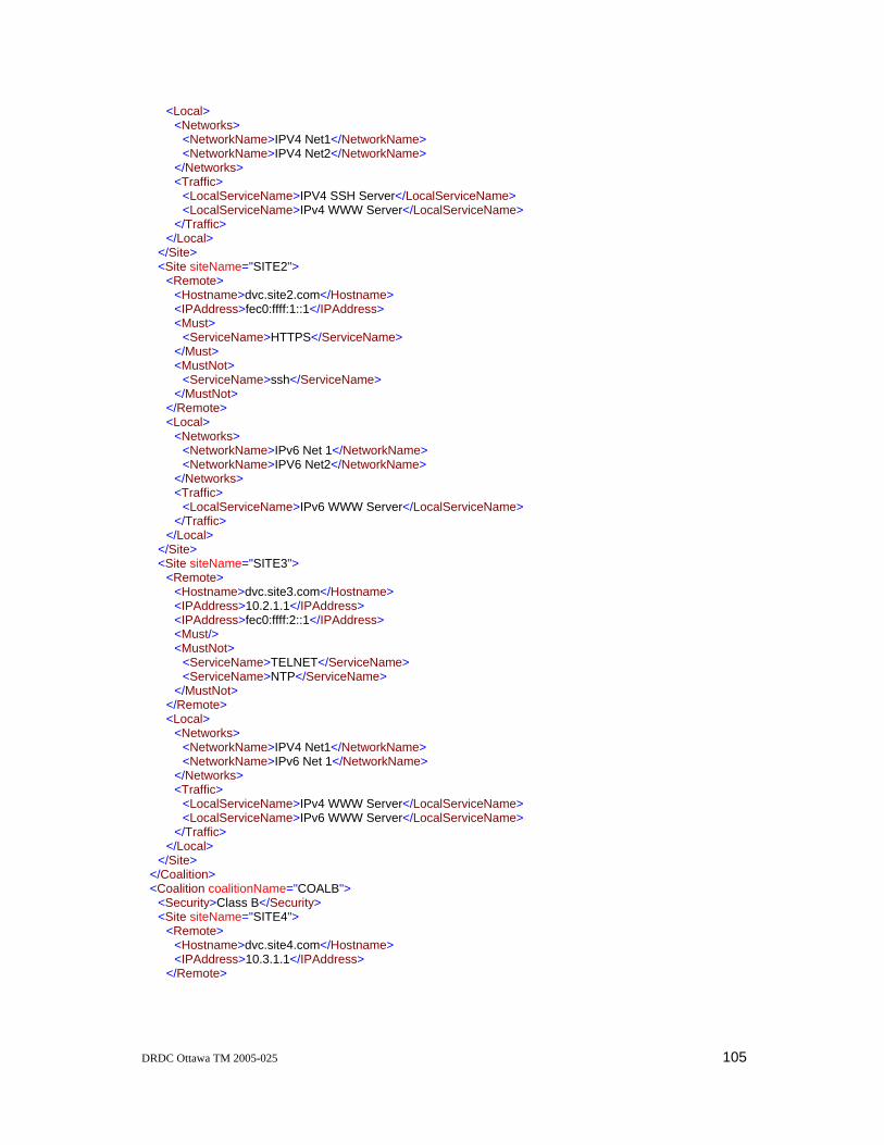
DRDC Ottawa TM 2005-025 105
<Local> <Networks> <NetworkName>IPV4 Net1</NetworkName> <NetworkName>IPV4 Net2</NetworkName> </Networks> <Traffic> <LocalServiceName>IPV4 SSH Server</LocalServiceName> <LocalServiceName>IPv4 WWW Server</LocalServiceName> </Traffic> </Local> </Site> <Site siteName="SITE2"> <Remote> <Hostname>dvc.site2.com</Hostname> <IPAddress>fec0:ffff:1::1</IPAddress> <Must> <ServiceName>HTTPS</ServiceName> </Must> <MustNot> <ServiceName>ssh</ServiceName> </MustNot> </Remote> <Local> <Networks> <NetworkName>IPv6 Net 1</NetworkName> <NetworkName>IPV6 Net2</NetworkName> </Networks> <Traffic> <LocalServiceName>IPv6 WWW Server</LocalServiceName> </Traffic> </Local> </Site> <Site siteName="SITE3"> <Remote> <Hostname>dvc.site3.com</Hostname> <IPAddress>10.2.1.1</IPAddress> <IPAddress>fec0:ffff:2::1</IPAddress> <Must/> <MustNot> <ServiceName>TELNET</ServiceName> <ServiceName>NTP</ServiceName> </MustNot> </Remote> <Local> <Networks> <NetworkName>IPV4 Net1</NetworkName> <NetworkName>IPv6 Net 1</NetworkName> </Networks> <Traffic> <LocalServiceName>IPv4 WWW Server</LocalServiceName> <LocalServiceName>IPv6 WWW Server</LocalServiceName> </Traffic> </Local> </Site> </Coalition> <Coalition coalitionName="COALB"> <Security>Class B</Security> <Site siteName="SITE4"> <Remote> <Hostname>dvc.site4.com</Hostname> <IPAddress>10.3.1.1</IPAddress> </Remote>

106 DRDC Ottawa TM 2005-025
<Local> <Networks> <NetworkName>IPV4 Net2</NetworkName> </Networks> </Local> </Site> </Coalition> </Policy>

DRDC Ottawa TM 2005-025 107
Annex G: DVC Policy Specification File Schema <xsd:schema xmlns:xsd="http://www.w3.org/2001/XMLSchema"> <xsd:element name="Policy"> <xsd:complexType> <xsd:sequence> <xsd:element ref="EnforcementPoints"/> <xsd:element ref="LocalNetworks"/> <xsd:element ref="Services"/> <xsd:element ref="LocalDomains"/> <xsd:element ref="LocalServers"/> <xsd:element ref="LocalServices"/> <xsd:element ref="Coalition" minOccurs="0" maxOccurs="unbounded"/> </xsd:sequence> </xsd:complexType> </xsd:element> <xsd:element name="EnforcementPoints"> <xsd:complexType> <xsd:sequence> <xsd:element name="DVC" minOccurs="0" maxOccurs="unbounded"> <xsd:complexType> <xsd:sequence> <xsd:element name="Hostname" type="FQDNType"/> <xsd:element name="IPAddress" type="IPAddressType"/> </xsd:sequence> </xsd:complexType> </xsd:element> </xsd:sequence> </xsd:complexType> </xsd:element> <xsd:element name="LocalNetworks"> <xsd:complexType> <xsd:sequence> <xsd:element name="IPNetwork" minOccurs="0" maxOccurs="unbounded"> <xsd:complexType> <xsd:sequence> <xsd:element name="IPAddress" type="IPAddressType"/> <xsd:element name="IPNetmask" type="IPAddressType"/> </xsd:sequence> <xsd:attribute name="networkName" type="xsd:string" use="required"/> </xsd:complexType> </xsd:element> </xsd:sequence> </xsd:complexType> </xsd:element> <xsd:element name="LocalServers"> <xsd:complexType> <xsd:sequence> <xsd:element name="IPServer" minOccurs="0" maxOccurs="unbounded"> <xsd:complexType> <xsd:sequence> <xsd:element name="Host" type="xsd:string"/> <xsd:element name="Domain" type="FQDNType"/> </xsd:sequence> <xsd:attribute name="serverName" type="xsd:string" use="required"/> </xsd:complexType> </xsd:element> </xsd:sequence> </xsd:complexType> </xsd:element>

108 DRDC Ottawa TM 2005-025
<xsd:element name="Services"> <xsd:complexType> <xsd:sequence> <xsd:element name="Service" minOccurs="0" maxOccurs="unbounded"> <xsd:complexType> <xsd:sequence> <xsd:element name="Protocol"> <xsd:complexType> <xsd:sequence> <xsd:element name="Port" type="PortType"/> </xsd:sequence> <xsd:attribute name="protocol" type="ProtocolType" use="required"/> </xsd:complexType> </xsd:element> </xsd:sequence> <xsd:attribute name="serviceName" type="xsd:string" use="required"/> </xsd:complexType> </xsd:element> </xsd:sequence> </xsd:complexType> </xsd:element> <xsd:element name="LocalDomains"> <xsd:complexType> <xsd:sequence> <xsd:element name="Zone" minOccurs="0" maxOccurs="unbounded"> <xsd:complexType> <xsd:sequence> <xsd:element name="MX"> <xsd:complexType> <xsd:sequence> <xsd:element name="IPAddress" type="IPAddressType"/> </xsd:sequence> <xsd:attribute name="mailExchanger" type="HostnameType" use="required"/> </xsd:complexType> </xsd:element> <xsd:element name="Host" minOccurs="0" maxOccurs="unbounded"> <xsd:complexType> <xsd:sequence> <xsd:element name="Hostname" type="HostnameType"/> <xsd:element name="IPAddress" type="IPAddressType"/> </xsd:sequence> <xsd:attribute name="Name" type="xsd:string" use="required"/> </xsd:complexType> </xsd:element> </xsd:sequence> <xsd:attribute name="domain" type="FQDNType" use="required"/> </xsd:complexType> </xsd:element> </xsd:sequence> </xsd:complexType> </xsd:element> <xsd:element name="LocalServices"> <xsd:complexType> <xsd:sequence> <xsd:element name="ExportedService" minOccurs="0" maxOccurs="unbounded"> <xsd:complexType> <xsd:sequence> <xsd:element name="ServerName" type="xsd:string"/> <xsd:element name="ServiceName" type="xsd:string"/> </xsd:sequence> <xsd:attribute name="exportedServiceName" type="xsd:string" use="required"/> </xsd:complexType>

DRDC Ottawa TM 2005-025 109
</xsd:element> </xsd:sequence> </xsd:complexType> </xsd:element> <xsd:element name="Coalition"> <xsd:complexType> <xsd:sequence> <xsd:element name="Security" type="xsd:string"/> <xsd:element name="Site" minOccurs="0" maxOccurs="unbounded"> <xsd:complexType> <xsd:sequence> <xsd:element name="Remote"> <xsd:complexType> <xsd:sequence> <xsd:element name="Hostname" type="FQDNType"/> <xsd:element name="IPAddress" type="IPAddressType" maxOccurs="2"/> <xsd:element name="Must" minOccurs="0"> <xsd:complexType> <xsd:sequence> <xsd:element name="ServiceName" type="xsd:string" minOccurs="0" maxOccurs="unbounded"/> </xsd:sequence> </xsd:complexType> </xsd:element> <xsd:element name="MustNot" minOccurs="0"> <xsd:complexType> <xsd:sequence> <xsd:element name="ServiceName" type="xsd:string" minOccurs="0" maxOccurs="unbounded"/> </xsd:sequence> </xsd:complexType> </xsd:element> </xsd:sequence> </xsd:complexType> </xsd:element> <xsd:element name="Local"> <xsd:complexType> <xsd:sequence> <xsd:element name="Networks" minOccurs="0"> <xsd:complexType> <xsd:sequence> <xsd:element name="NetworkName" type="xsd:string" minOccurs="0" maxOccurs="unbounded"/> </xsd:sequence> </xsd:complexType> </xsd:element> <xsd:element name="Traffic" minOccurs="0"> <xsd:complexType> <xsd:sequence> <xsd:element name="LocalServiceName" type="xsd:string" minOccurs="0" maxOccurs="unbounded"/> </xsd:sequence> </xsd:complexType> </xsd:element> </xsd:sequence> </xsd:complexType> </xsd:element> </xsd:sequence> <xsd:attribute name="siteName" type="xsd:string" use="required"/> </xsd:complexType> </xsd:element> </xsd:sequence>

110 DRDC Ottawa TM 2005-025
<xsd:attribute name="coalitionName" type="xsd:string" use="required"/> </xsd:complexType> </xsd:element> <xsd:simpleType name="NameType"> <xsd:restriction base="xsd:string"> <xsd:whiteSpace value="collapse"/> <xsd:pattern value="[A-Z][A-Z0-9]*"/> </xsd:restriction> </xsd:simpleType> <xsd:simpleType name="SecurityType"> <xsd:restriction base="xsd:string"> <xsd:whiteSpace value="collapse"/> <xsd:pattern value="Class [A-Z]"/> </xsd:restriction> </xsd:simpleType> <xsd:simpleType name="IPAddressType"> <xsd:restriction base="xsd:string"> <xsd:whiteSpace value="collapse"/> <xsd:pattern value="((([0-9]{1,2})|([0-1][0-9]{1,2})|(2[0-4][0-9])|(25[0-5]))\.){3}((([0-9]{1,2})|([0-1][0-9]{1,2})|(2[0-4][0-9])|(25[0-5])))"/> <xsd:pattern value="(([0-9A-Fa-f]{1,4}):){7}[0-9A-Fa-f]{1,4}"/> <xsd:pattern value="(([0-9a-fA-F]){0,4}:){7}(([0-9a-fA-F]){0,4}){0,1}"/> <xsd:pattern value="(([0-9a-fA-F]){0,4}:){0,7}:(([0-9a-fA-F]){0,4}:){0,7}(([0-9a-fA-F]){0,4}){0,1}"/> </xsd:restriction> </xsd:simpleType> <xsd:simpleType name="FQDNType"> <xsd:restriction base="xsd:string"> <xsd:whiteSpace value="collapse"/> <xsd:pattern value="([a-z0-9\-]+\.)+[a-z]+"/> </xsd:restriction> </xsd:simpleType> <xsd:simpleType name="HostnameType"> <xsd:restriction base="xsd:string"> <xsd:whiteSpace value="collapse"/> <xsd:pattern value="[a-z0-9\-]+"/> </xsd:restriction> </xsd:simpleType> <xsd:simpleType name="PortType"> <xsd:restriction base="PortNumType"/> </xsd:simpleType> <xsd:simpleType name="PortNumType"> <xsd:restriction base="xsd:int"> <xsd:minInclusive value="0"/> <xsd:maxInclusive value="65535"/> <xsd:whiteSpace value="collapse"/> </xsd:restriction> </xsd:simpleType> <xsd:simpleType name="PortNameType"> <xsd:restriction base="xsd:string"> <xsd:whiteSpace value="collapse"/> <xsd:pattern value="[a-z]+[a-z0-9\-]*"/> </xsd:restriction> </xsd:simpleType> <xsd:simpleType name="ProtocolType"> <xsd:restriction base="xsd:string"> <xsd:pattern value="tcp|udp|icmp|6|17|1"/> </xsd:restriction> </xsd:simpleType> </xsd:schema>

DRDC Ottawa TM 2005-025 111
Annex H: Example DVC Policy Configuration File <Policy xmlns:jxb="http://java.sun.com/xml/ns/jaxb" xmlns:xsi="http://www.w3.org/2001/XMLSchema-instance" xsi:noNamespaceSchemaLocation="dvc-parser-dvc.xsd"> <Coalition coalitionName="COALA"> <Security>Class A</Security> <Site siteName="SITE1"> <Remote> <Hostname>dvc.site1.com</Hostname> <IPAddress>10.1.1.1</IPAddress> <Traffic> <Must> <Protocol Protocol="tcp"> <Port>80</Port> </Protocol> <Protocol Protocol="tcp"> <Port>25</Port> </Protocol> </Must> <MustNot> <Protocol Protocol="udp"> <Port>123</Port> </Protocol> <Protocol Protocol="tcp"> <Port>23</Port> </Protocol> </MustNot> </Traffic> </Remote> <Local> <Networks> <Network network="10.10.2.0"> <IPNetmask>255.255.255.0</IPNetmask> </Network> <Network network="10.10.3.0"> <IPNetmask>255.255.255.0</IPNetmask> </Network> </Networks> <DNS> <Zone Domain="domain1.local.com"> <MX MailExchanger="smtp"> <IPAddress>10.10.2.25</IPAddress> </MX> <Host Hostname="ssh"> <IPAddress>10.10.2.22</IPAddress> </Host> </Zone> </DNS> <Traffic> <Server> <IPAddress>10.10.2.22</IPAddress> <Protocol Protocol="tcp"> <Port>22</Port> </Protocol> </Server> <Server> <IPAddress>10.10.2.25</IPAddress> <Protocol Protocol="tcp"> <Port>25</Port> </Protocol>

112 DRDC Ottawa TM 2005-025
</Server> </Traffic> </Local> </Site> <Site siteName="SITE2"> <Remote> <Hostname>dvc.site2.com</Hostname> <IPAddress>fec0:ffff:1::1</IPAddress> <Traffic> <Must> <Protocol Protocol="tcp"> <Port>443</Port> </Protocol> </Must> <MustNot> <Protocol Protocol="tcp"> <Port>22</Port> </Protocol> </MustNot> </Traffic> </Remote> <Local> <Networks> <Network network="fec0:ffff:10:1::"> <IPNetmask>ffff:ffff:ffff:ffff::</IPNetmask> </Network> <Network network="fec0:ffff:10:2::"> <IPNetmask>ffff:ffff:ffff:ffff::</IPNetmask> </Network> </Networks> <DNS> <Zone Domain="domain1.local.com"> <MX MailExchanger="smtp"> <IPAddress>fec0:ffff:10:2::25</IPAddress> </MX> <Host Hostname="https"> <IPAddress>fec0:ffff:10:2::443</IPAddress> </Host> </Zone> </DNS> <Traffic> <Server> <IPAddress>fec0:ffff:10:2::443</IPAddress> <Protocol Protocol="tcp"> <Port>443</Port> </Protocol> </Server> </Traffic> </Local> </Site> <Site siteName="SITE3"> <Remote> <Hostname>dvc.site3.com</Hostname> <IPAddress>10.2.1.1</IPAddress> <IPAddress>fec0:ffff:2::1</IPAddress> <Traffic> <Must> <Protocol Protocol="tcp"> <Port>23</Port> </Protocol> </Must> </Traffic>

DRDC Ottawa TM 2005-025 113
</Remote> <Local> <Networks> <Network network="10.10.2.0"> <IPNetmask>255.255.255.0</IPNetmask> </Network> <Network network="fec0:ffff:10:2::"> <IPNetmask>ffff:ffff:ffff:ffff::</IPNetmask> </Network> </Networks> <DNS> <Zone Domain="domain1local.com"> <MX MailExchanger="smtp"> <IPAddress>10.10.2.25</IPAddress> </MX> <Host Hostname="ssh"> <IPAddress>10.10.2.22</IPAddress> </Host> <Host Hostname="sshv6"> <IPAddress>fec0:ffff:10:2::1</IPAddress> </Host> </Zone> </DNS> <Traffic> <Server> <IPAddress>10.10.2.22</IPAddress> <Protocol Protocol="tcp"> <Port>22</Port> </Protocol> </Server> <Server> <IPAddress>fec0:ffff:10:2::1</IPAddress> <Protocol Protocol="tcp"> <Port>22</Port> </Protocol> </Server> </Traffic> </Local> </Site> </Coalition> <Coalition coalitionName="COALB"> <Security>Class B</Security> <Site siteName="SITE4"> <Remote> <Hostname>dvc.site4.com</Hostname> <IPAddress>10.3.1.1</IPAddress> <Traffic> <Must> <Protocol Protocol="tcp"> <Port>80</Port> </Protocol> <Protocol Protocol="tcp"> <Port>25</Port> </Protocol> </Must> <MustNot> <Protocol Protocol="udp"> <Port>123</Port> </Protocol> <Protocol Protocol="tcp"> <Port>23</Port> </Protocol>
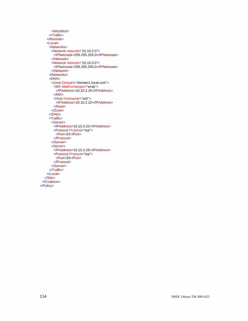
114 DRDC Ottawa TM 2005-025
</MustNot> </Traffic> </Remote> <Local> <Networks> <Network network="10.10.2.0"> <IPNetmask>255.255.255.0</IPNetmask> </Network> <Network network="10.10.3.0"> <IPNetmask>255.255.255.0</IPNetmask> </Network> </Networks> <DNS> <Zone Domain="domain1.local.com"> <MX MailExchanger="smtp"> <IPAddress>10.10.2.25</IPAddress> </MX> <Host Hostname="ssh"> <IPAddress>10.10.2.22</IPAddress> </Host> </Zone> </DNS> <Traffic> <Server> <IPAddress>10.10.3.22</IPAddress> <Protocol Protocol="tcp"> <Port>22</Port> </Protocol> </Server> <Server> <IPAddress>10.10.3.25</IPAddress> <Protocol Protocol="tcp"> <Port>25</Port> </Protocol> </Server> </Traffic> </Local> </Site> </Coalition> </Policy>

DRDC Ottawa TM 2005-025 115
Annex I: DVC Policy Configuration File Schema <xsd:schema xmlns:jxb="http://java.sun.com/xml/ns/jaxb" xmlns:xsd="http://www.w3.org/2001/XMLSchema" jxb:version="1.0"> <xsd:element name="Policy"> <xsd:annotation> <xsd:appinfo> <jxb:class name="EpPolicy"/> </xsd:appinfo> </xsd:annotation> <xsd:complexType> <xsd:sequence> <xsd:element ref="Coalition" minOccurs="0" maxOccurs="unbounded"/> </xsd:sequence> </xsd:complexType> </xsd:element> <xsd:simpleType name="NameType"> <xsd:restriction base="xsd:string"> <xsd:whiteSpace value="collapse"/> <xsd:pattern value="[A-Z][A-Z0-9]*"/> </xsd:restriction> </xsd:simpleType> <xsd:simpleType name="SecurityType"> <xsd:restriction base="xsd:string"> <xsd:whiteSpace value="collapse"/> <xsd:pattern value="Class [A-Z]"/> </xsd:restriction> </xsd:simpleType> <xsd:simpleType name="IPAddressType"> <xsd:restriction base="xsd:string"> <xsd:whiteSpace value="collapse"/> <xsd:pattern value="((([0-9]{1,2})|([0-1][0-9]{1,2})|(2[0-4][0-9])|(25[0-5]))\.){3}((([0-9]{1,2})|([0-1][0-9]{1,2})|(2[0-4][0-9])|(25[0-5])))"/> <xsd:pattern value="(([0-9A-Fa-f]{1,4}):){7}[0-9A-Fa-f]{1,4}"/> <xsd:pattern value="(([0-9a-fA-F]){0,4}:){7}(([0-9a-fA-F]){0,4}){0,1}"/> <xsd:pattern value="(([0-9a-fA-F]){0,4}:){0,7}:(([0-9a-fA-F]){0,4}:){0,7}(([0-9a-fA-F]){0,4}){0,1}"/> </xsd:restriction> </xsd:simpleType> <xsd:simpleType name="FQDNType"> <xsd:restriction base="xsd:string"> <xsd:whiteSpace value="collapse"/> <xsd:pattern value="([a-z0-9\-]+\.)+[a-z]+"/> </xsd:restriction> </xsd:simpleType> <xsd:simpleType name="HostnameType"> <xsd:restriction base="xsd:string"> <xsd:whiteSpace value="collapse"/> <xsd:pattern value="[a-z0-9\-]+[^\.]"/> </xsd:restriction> </xsd:simpleType> <xsd:simpleType name="ProtocolType"> <xsd:restriction base="xsd:string"> <xsd:pattern value="tcp|udp|icmp|6|17|1"/> </xsd:restriction> </xsd:simpleType> <xsd:simpleType name="PortType"> <xsd:union memberTypes="PortNameType PortNumType"/> </xsd:simpleType> <xsd:simpleType name="PortNumType"> <xsd:restriction base="xsd:int">

116 DRDC Ottawa TM 2005-025
<xsd:minInclusive value="1"/> <xsd:maxInclusive value="65535"/> <xsd:whiteSpace value="collapse"/> </xsd:restriction> </xsd:simpleType> <xsd:simpleType name="PortNameType"> <xsd:restriction base="xsd:string"> <xsd:whiteSpace value="collapse"/> <xsd:pattern value="[a-z]+[a-z0-9\-]*"/> </xsd:restriction> </xsd:simpleType> <xsd:element name="Coalition"> <xsd:annotation> <xsd:appinfo> <jxb:class name="EpCoalition"/> </xsd:appinfo> </xsd:annotation> <xsd:complexType> <xsd:annotation> <xsd:appinfo> <jxb:class name="EpCoalitionType"/> </xsd:appinfo> </xsd:annotation> <xsd:sequence> <xsd:element name="Security" type="xsd:string"/> <xsd:element name="Site" minOccurs="0" maxOccurs="unbounded"> <xsd:complexType> <xsd:sequence> <xsd:element name="Remote"> <xsd:complexType> <xsd:sequence> <xsd:element name="Hostname" type="FQDNType"/> <xsd:element name="IPAddress" type="IPAddressType" maxOccurs="2"/> <xsd:element name="Traffic" minOccurs="0"> <xsd:complexType> <xsd:sequence> <xsd:element name="Must" minOccurs="0"> <xsd:complexType> <xsd:sequence> <xsd:element name="Protocol" minOccurs="0" maxOccurs="unbounded"> <xsd:complexType> <xsd:sequence> <xsd:element name="Port" type="PortNumType"/> </xsd:sequence> <xsd:attribute name="Protocol" type="ProtocolType" use="required"/> </xsd:complexType> </xsd:element> </xsd:sequence> </xsd:complexType> </xsd:element> <xsd:element name="MustNot" minOccurs="0"> <xsd:complexType> <xsd:sequence> <xsd:element name="Protocol" minOccurs="0" maxOccurs="unbounded"> <xsd:complexType> <xsd:sequence> <xsd:element name="Port" type="PortNumType"/> </xsd:sequence> <xsd:attribute name="Protocol" type="ProtocolType" use="required"/> </xsd:complexType> </xsd:element> </xsd:sequence>

DRDC Ottawa TM 2005-025 117
</xsd:complexType> </xsd:element> </xsd:sequence> </xsd:complexType> </xsd:element> </xsd:sequence> </xsd:complexType> </xsd:element> <xsd:element name="Local"> <xsd:complexType> <xsd:sequence> <xsd:element name="Networks" minOccurs="0"> <xsd:complexType> <xsd:sequence> <xsd:element name="Network" minOccurs="0" maxOccurs="unbounded"> <xsd:complexType> <xsd:sequence> <xsd:element name="IPNetmask" type="IPAddressType"/> </xsd:sequence> <xsd:attribute name="network" type="IPAddressType" use="required"/> </xsd:complexType> </xsd:element> </xsd:sequence> </xsd:complexType> </xsd:element> <xsd:element name="DNS" minOccurs="0"> <xsd:complexType> <xsd:sequence> <xsd:element name="Zone" minOccurs="0" maxOccurs="unbounded"> <xsd:complexType> <xsd:sequence> <xsd:element name="MX"> <xsd:complexType> <xsd:sequence> <xsd:element name="IPAddress" type="IPAddressType"/> </xsd:sequence> <xsd:attribute name="MailExchanger" type="HostnameType" use="required"/> </xsd:complexType> </xsd:element> <xsd:element name="Host" minOccurs="0" maxOccurs="unbounded"> <xsd:complexType> <xsd:sequence> <xsd:element name="IPAddress" type="IPAddressType"/> </xsd:sequence> <xsd:attribute name="Hostname" type="HostnameType" use="required"/> </xsd:complexType> </xsd:element> </xsd:sequence> <xsd:attribute name="Domain" type="FQDNType" use="required"/> </xsd:complexType> </xsd:element> </xsd:sequence> </xsd:complexType> </xsd:element> <xsd:element name="Traffic" minOccurs="0"> <xsd:complexType> <xsd:sequence> <xsd:element name="Server" minOccurs="0" maxOccurs="unbounded"> <xsd:complexType> <xsd:sequence> <xsd:element name="IPAddress" type="IPAddressType"/> <xsd:element name="Protocol">

118 DRDC Ottawa TM 2005-025
<xsd:complexType> <xsd:sequence> <xsd:element name="Port" type="PortNumType"/> </xsd:sequence> <xsd:attribute name="Protocol" type="ProtocolType" use="required"/> </xsd:complexType> </xsd:element> </xsd:sequence> </xsd:complexType> </xsd:element> </xsd:sequence> </xsd:complexType> </xsd:element> </xsd:sequence> </xsd:complexType> </xsd:element> </xsd:sequence> <xsd:attribute name="siteName" type="NameType" use="required"/> </xsd:complexType> </xsd:element> </xsd:sequence> <xsd:attribute name="coalitionName" type="NameType" use="required"/> </xsd:complexType> </xsd:element> </xsd:schema>

DRDC Ottawa TM 2005-025 119
List of symbols and abbreviations
ASE Autonomous System External
C4ISR Communications, Command, Control, Computers, Intelligence, Surveillance and Reconnaissance
CA Certificate Authority
CIM Common Information Model
CMS Cryptographic Message Syntax
CN Common Name
COPS Common Open Policy Service
CSR Certificate Signing Request
DNS Domain Name Service
DRDC Defence R&D Canada
DND Department of National Defence
DVC Dynamic VPN Controller
ESP Encapsulated Security Payload
FQDN Fully Qualified Domain Name
IKE Internet Key Exchange
INSC Interoperable Networks for Secure Communication
ISP Internet Service Provider
IPv4 Internet Protocol Version 4
IPv6 Internet Protocol Version 6
ISI Information Sciences Institute
OSPF Open Shortest Path First
PBNM Policy Based Network Management
PEM Privacy Enhanced Mail
PEP Policy Enforcement Point

120 DRDC Ottawa TM 2005-025
PKCS Public Key Cryptography Standards
PKI Public Key Infrastructure
RIP Routing Information Protocol
SA Security Association
SCVP Simple Certification Verification Protocol
SPI Security Parameter Index
SSL Secure Socket Layer
UCL University College London
UMU University of Murcia
VPN Virtual Private Network
WAN Wide Area Network
XML eXtensible Markup Language

DRDC Ottawa TM 2005-025 121
Glossary Coalition A coalition is a collection of sites that require secure access to each other’s
computer system assets. Coalition membership is defined locally and is not centrally controlled. As a result coalition membership may vary from site to site.
DVC Control Session The SSL secured TCP channel, authenticated using X.509 certificates and used for DVC to DVC communication. This channel is used by the DVC Process to exchange messages between DVCs to establish VPNs, dismantle VPNs and report status about the VPNs configured within a coalition.
DVC Demonstrator This is the official name for the system described in this document. This system is not a ‘production ready’ system; it is a demonstrator system that facilitates experimentation with dynamic VPNs and inter-domain policy exchange. The terms “DVC”, “DVC Enforcement Point” or “DVC system” are often used instead of “DVC Demonstrator”.
DVC Management Console This is the Web based ‘cgi’ scripts that the DVC Operator access using a Web browser to establish, dismantle and monitor VPNs.
DVC Operator This is the individual responsible for establishing, dismantling and monitoring VPNs with the use of the DVC Management Console.
DVC Policy Editor This ‘Java’ application is used by the DVC Security Officer to build the DVC Policy Specification File, convert it to the DVC Policy Configuration File and install on the local DVC System.
DVC Policy Configuration File The Policy Configuration File contains the DVC Policy and is used by the DVC Process.
DVC Policy Database This database is an internal data structure within the DVC Process. It contains the DVC Policy as well as status and state information for each remote peer.
DVC Policy Specification File The Policy Configuration File contains the DVC Policy and is used by the DVC Policy Editor.
DVC Process This term refers to the major component of the DVC System. It is the main ‘Perl’ code that interfaces with the DVC Management Console, DVC Policy Editor, sub-system modules and with other DVC systems.
DVC Security Officer This is the individual responsible for defining the DVC Policy Specification with the use of the DVC Policy Editor.
DVC System This term refers to all the DVC components which are co-located with the DVC Process. These components consist of the DVC Process, the four sub-systems modules and the DVC Management Console.
Firewall Subsystem The software package (IP Filter) on the DVC System that is used to filter IP packets based on source address, destination address, source port and destination port.
Initiating DVC This is the DVC system that initiated the DVC Control session.
IPsec Parameters The configuration information required to configure the IPsec Kernel component. This information consists of authentication and encryption algorithms and key lengths.

122 DRDC Ottawa TM 2005-025
IPsec SA An IPsec security association is a connection between two VPN devices that provides agreed security services to the traffic carried over this connection.
IPsec Subsystem The FreeBSD Kernel component (KAME) used to encrypt / decrypt and authenticate IP packets to form the VPN.
Key Material Symmetric keys used for the encryption and authentication of the ESP packets.
Local Policy Information This is the list of local networks, services and name bindings which will be exported to the remote peer.
PKCS #7 The PKCS#7 standard describes a general syntax for data that may have cryptography applied to it, such as digital signatures and digital envelopes. A case of the syntax provides a means for disseminating certificates and certificate-revocation lists based upon a PKCS#10 request.
PKCS #10 The PKCS#10 standard describes syntax for certification requests. A certification request consists of a distinguished name, a public key, and optionally a set of attributes, collectively signed by the entity requesting certification. Certification requests are sent to a certification authority, who transforms the request to an X.509 public-key certificate.
PKCS #12 The PKCS#12 standard describes syntax for storing or transporting a user's private keys, certificates, miscellaneous secrets, etc.
PKIX-CMC PKIX-CMC supports the exchange of PKI messages using the Cryptographic Message Syntax (CMS) as the transaction envelope. CMS, which was developed as part of S/MIME, provides a superset of PKCS #7
Remote Peer The DVC located a remote coalition member site.
Remote Policy Information This is the list of services that the remote peer must provide and list of services that the remote peer must not provide.
Responding DVC This is the DVC system that responds to the initiating DVC.
Routing Subsystem The software package (Zebra) on the DVC System that is used to advertise routes available via the VPN.
Site A Coalition member that requires access to local network services or that provides network services to local networks.
X.509 Certificate This is a digital certificate that contains the public key of an individual or device. The DVC Systems uses digital certificates to authenticate DVC Control sessions, DVC Operators and DVC Security Officers.

UNCLASSIFIED SECURITY CLASSIFICATION OF FORM
(highest classification of Title, Abstract, Keywords)
DOCUMENT CONTROL DATA (Security classification of title, body of abstract and indexing annotation must be entered when the overall document is classified)
1. ORIGINATOR (the name and address of the organization preparing the document. Organizations for whom the document was prepared, e.g. Establishment sponsoring a contractor’s report, or tasking agency, are entered in section 8.)
Defence R&D Canada – Ottawa Ottawa, ON K1A 0Z4
2. SECURITY CLASSIFICATION (overall security classification of the document,
including special warning terms if applicable) UNCLASSIFIED
3. TITLE (the complete document title as indicated on the title page. Its classification should be indicated by the appropriate abbreviation (S,C or U) in parentheses after the title.)
The Dynamic VPN Controller (U)
4. AUTHORS (Last name, first name, middle initial)
Zeber, Dr. S., Spagnolo, J., Cayer, D.
5. DATE OF PUBLICATION (month and year of publication of document)
March 2005
6a. NO. OF PAGES (total containing information. Include Annexes, Appendices, etc.)
122
6b. NO. OF REFS (total cited in document)
8
7. DESCRIPTIVE NOTES (the category of the document, e.g. technical report, technical note or memorandum. If appropriate, enter the type of report, e.g. interim, progress, summary, annual or final. Give the inclusive dates when a specific reporting period is covered.)
Technical Memorandum
8. SPONSORING ACTIVITY (the name of the department project office or laboratory sponsoring the research and development. Include the address.)
NIO section, DRDC Ottawa 3701 Carling Avenue Ottawa K1A 0Z4
9a. PROJECT OR GRANT NO. (if appropriate, the applicable research and development project or grant number under which the document was written. Please specify whether project or grant)
5BF27
9b. CONTRACT NO. (if appropriate, the applicable number under which the document was written)
10a. ORIGINATOR’S DOCUMENT NUMBER (the official document number by which the document is identified by the originating activity. This number must be unique to this document.)
DRDC Ottawa TM 2005-025
10b. OTHER DOCUMENT NOS. (Any other numbers which may be assigned this document either by the originator or by the sponsor)
11. DOCUMENT AVAILABILITY (any limitations on further dissemination of the document, other than those imposed by security classification) ( X ) Unlimited distribution ( ) Distribution limited to defence departments and defence contractors; further distribution only as approved ( ) Distribution limited to defence departments and Canadian defence contractors; further distribution only as approved ( ) Distribution limited to government departments and agencies; further distribution only as approved ( ) Distribution limited to defence departments; further distribution only as approved ( ) Other (please specify): ����������
12. DOCUMENT ANNOUNCEMENT (any limitation to the bibliographic announcement of this document. This will normally correspond to
the Document Availability (11). However, where further distribution (beyond the audience specified in 11) is possible, a wider announcement audience may be selected.)
Unlimited
UNCLASSIFIED
SECURITY CLASSIFICATION OF FORM DDCCDD0033 22//0066//8877

UNCLASSIFIED SECURITY CLASSIFICATION OF FORM
13. ABSTRACT ( a brief and factual summary of the document. It may also appear elsewhere in the body of the document itself. It is highly desirable that the abstract of classified documents be unclassified. Each paragraph of the abstract shall begin with an indication of the security classification of the information in the paragraph (unless the document itself is unclassified) represented as (S), (C), or (U). It is not necessary to include here abstracts in both official languages unless the text is bilingual).
Defence R&D Canada (DRDC) developed the dynamic virtual private network controller (DVC) prototype as a concept demonstrator for the rapid deployment and self-configuration of one or more dynamic coalition virtual private networks (VPNs), and has demonstrated the DVC prototype in both local and international environments. The DRDC DVC prototype is a network boundary protection device that provides access to its protected network infrastructure in a controlled fashion to one or more approved coalition partners without requiring any knowledge of a remote partner’s protected network infrastructure. This report describes the design and operation of the DVC prototype, its current state of development, and the ongoing work to evolve the DVC capabilities for policy-based management and dynamic configuration. The DVC prototype provides a flexible, interoperable, application-independent solution for secure information exchange that does not require any knowledge of a remote partner’s network infrastructure. The development of the DVC capability supports the strategic C4ISR goal of an enhanced capability for secure information interchange for military operations.
14. KEYWORDS, DESCRIPTORS or IDENTIFIERS (technically meaningful terms or short phrases that characterize a document and could be helpful in cataloguing the document. They should be selected so that no security classification is required. Identifiers such as equipment model designation, trade name, military project code name, geographic location may also be included. If possible keywords should be selected from a published thesaurus. e.g. Thesaurus of Engineering and Scientific Terms (TEST) and that thesaurus-identified. If it is not possible to select indexing terms which are Unclassified, the classification of each should be indicated as with the title.)
Dynamic coalition networks Dynamic VPNs IPv6 IPsec Network security PKI Policy management Policy negotiation VPN technology X.509 authentication
UNCLASSIFIED
SECURITY CLASSIFICATION OF FORM

