the effect of strain rate and temperature on the lcf
TRANSCRIPT

Abstract
THE EFFECT OF STRAIN RATE AND TEMPERATURE ON THE LCF BEHAVIOR OF THE ODS NICKELBASE SUPERALLOY PM 1000
Martin Heilmaierl, Michel Nganbel, Frank E.H. Miiller2, Ludwig Schultz’
‘Institute of Solid State and Materials Research Dresden, D-01171 Dresden, Germany 2Plansee GmbH Lechbruck, D-86983 Lechbruck, Germany
The high temperature LCF behavior of the oxide dispersion strengthened (ODS) nickel-base superalloy PM 1000 was studied using single-step tests with constant total strain amplitudes ranging from 0.2 to 0.7%. Specifically, the effect of varying strain rate and temperature on the cyclic lifetimes as well as on the fatigue crack initiation and propagation was studied. It was found that a decrease of the applied strain rate by a factor of 100 drastically reduces cyclic lifetime whereas an increase of temperature by 150 K decreases Nf only moderately. This behavior can be qualitatively understood on the basis of post-mortem microstructural investigations of fatigued specimens which reveal pronounced void formation and coalescence at transverse grain boundaries followed by cleavage at longitudinal grain boundaries leading to failure.
Introduction
Oxide dispersion strengthened (ODS) superalloys produced by mechanical alloying (MA) technique (1,2) have recently received renewed attention from the scientific community and industry. This interest originates mainly from the potential of ODS superalloys for
structural applications, notably in gas turbine components, such as vanes or nozzles, where outstanding high temperature creep and fatigue resistance at temperatures of 1000 ‘C and higher are desirable.
In essence, PM lOOO* is a powder-metallurgical nickel- chromium solid solution additionally strengthened by nominally 1 vol.% of incoherent and thermally stable nano-scale Y20, particles dispersed in the metallic matrix by solid state reaction processing, i.e. mechanical alloying. Powder consolidation is subsequently followed by an extensive thermomechanical processing including hot extrusion and hot rolling. A final annealing treatment above 0.9 T, promotes secondary recrystallization leading to coarse and elongated grains up to several mm in length. However, the transverse grain boundaries have been considered to be weak links during high temperature deformation as they are the most probable locations for void formation and growth during service. Consequently, this highlights the major importance of the grain aspect ratio (GAR) in this class of alloys (3) Additionally, fine equiaxed grains - so called “recystallization defects“ - are present in the material which may - depending on their volume fraction - further weaken the materials
’ Trademark of Plansee GmbH, Lechbruck, Germany
Superalloys 2000 Edited by T.M. Pollock, R.D. Kissinger, R.R. Bowman,
K.A. Green, M. McLean, S. Olson, and J.J. Schiw TMS (The Minerals, Metals &Materials Society), 2000
593

deformation resistance(3-5). While the creep resistance of these ODS nickel-base superalloys is known to be outstanding - even superior to that of single crystal superalloys at temperatures around and beyond 1OOO’C - only a few reports deal with their low cycle fatigue (LCF) behavior (6,7).
including the effect of strain rate and temperature on the LCF behavior of PM 1000. Specifically, we will focus on the effect of void formation and growth upon damage and cyclic lifetime.
Experimental
200 pm
1 m
Radial direction
Figure 1: Grain structure of the investigated bar material of PM 1000; (a) cross-section, (b) longitudinal plane, (c) 3-dimensional sketch.
In this paper we have extended our previous work on the influence of orientation and grain structure (8) by
Material
PM 1000 having the nominal chemical composition (wt.%) of Ni-20Cr-OSAl-0.3Ti-0.6Yz03 was supplied in the fully recrystallized condition (final heat treatment: lh @ 1315 “C) in form of a hot extruded bar material (diameter 50 mm). The grain parameters were inspected by optical microscopy (OM) and the average length of the coarse grains was found to bc about 2.6 mm in longitudinal direction. In the transverse direction the diameter was about 0.25 mm, yielding a GAR of about 10, see Fig. 1. The orientation of individual grains was measured by scanning electron microscopy (SEM, Zeiss DSM 962) using electron back scatter diffraction (EBSD) as well as neutron diffraction. Both methods concurrently yield a strong <loo> fiber texture parallel to the extrusion (longitudinal) direction (Fig. 2).
Figure 2: (100) pole figure of the PM 1000 bar material, obtained by SEM and EBSD.
Transmission electron microscopy (TEM, Jeol CM 200 X) was used for investigating the particle and dislocation microstructure before and after fatigue deformation. Quantitative stereology was applied to determine the relevant particle parameters, namely the mean diameter d, the mean planar center-to-center spacing L, and the volume fraction f. The thickness of the TEM foils was determined by convergent beam electron diffraction. From micrographs such as Fig. 3 one obtains values of particle diameter d = 14 nm, interparticle spacing L = 100 nm,
594

and volume fraction f = 1.0 % nearly identical to that observed in Inconel MA 754 of comparable chemical composition (5). While the arrangement of most of the nano-scale dispersoids appears to be rather homogeneous or random in Fig. 3, relatively large inclusions in the micro-meter range were also detected. These inclusions were identified as titanium carbonitrides and cuboidal alumina. Though these large inclusions play little or no role in pinning dislocations, their role in pinning grain boundaries and in serving as nucleation sites for grain boundary cavities must be considered (5).
Figure 3: Bright field TEM micrograph of PM 1000 bar material, as-received condition.
Mechanical testing
For fatigue testing cylindrical specimens with threaded ends having a gage length of 12.5 mm and a gage diameter of 6 mm were produced by electro-erosion and subsequent machining such that the loading axes were parallel to the longitudinal direction. Prior to mechanical testing in air they were ground and polished to remove surface scratches. Cyclic symmetrical (R=-1) push-pull tests with triangular wave shape were carried out at the two different temperatures of 850” and 1000°C and at strain rates of 10” and 10m5 s-l. All tests were performed under total strain control representing the loading condition of engineering components like vanes or nozzles in gas turbines undergoing a certain degree of structural constraint. Total strain amplitudes E,~ were varied from 0.2 to 0.7%.
Results and discussion
Cyclic stress-strain response
Cyclic hardening/softening curves of PM 1000 at a strain rate of 10” s-l with different total strain amplitudes ~~~
ranging from 0.2 to 0.6% are plotted in Fig. 4a. In Fig. 4b
the cyclic stress response at a strain rate of 10“ s-l is displayed for r+ values ranging from 0.3 to 0.7%.
300
250
200 m
52 150 F.
o 100
number of cycles
. E = 10-5s-’
. . . . . . .._
85O“C
4ot 0.7% 0.5% 0.3%
\
50 -
0
\
b> c
lo1 lo2 lo3 number of cycles
Figure 4: Cyclic hardening / softening curves for different applied total strain amplitudes and strain rates of 10” se1 (a) and lo-’ s-l (b), respectively.
At 850°C curves with strain amplitudes less than 0.6% show initial cyclic softening which is, however, only weakly pronounced, followed by a region of fairly constant stress amplitudes which may be defined as the saturation stress level oqs (9). In contrast, specimens cycled at the higher temperature of 1000°C generally show continuous cyclic softening from the start of the test like those at 850°C with strain amplitudes of 0.6% and higher. In this case “saturation“ was defined at half life before the transition to a steeper decline of the curve indicates the onset of external necking in the specimen. Several points are obvious from Figs. 4a and b: first, at a given constant strain rate the saturation stress level CT,, for cyclic deformation decreases with increasing temperature. Second, at a given temperature tsqs decreases with decreasing strain amplitude. However, this effect is
595

Cvclic lifetime relatively weak. Third, the decrease of the applied strain rate leads to a dramatic reduction of the cyclic lifetimes Nr (note the different scale of the x-axis in Figs. 4a and b).
200
-200
i N=lO T= 850% i = 10”~-~
l,l,I,I,I,I, *,,,,,,,,,,,L
-0.6 -0.4 -0.2 0 0.2 0.4 0.6 E , %
Figure 5: Selected stabilized o-a-hysteresis loops with a total strain amplitude of aht = 0.6% (solid curves); dashed: cr-s+-hysteresis loops; testing temperatures and strain rates as indicated.
Fig. 5 depicts representative hysteresis loops obtained from fatigue tests conducted at aqt = 0.6% in the form of stress (0) vs. total strain (solid line) and plastic strain (dashed line), respectively. As discussed in detail in Ref. (lo), severe damage, which affects cyclic stress-strain response, occurs early in fatigue life under these tests conditions. Therefore, the hysteresis loops plotted in Fig. 5 were recorded after ten cycles in order to show the true cyclic stress-strain response of the (undamaged) material. Plastic strain (~1) was obtained by subtracting the elastic strain (se,) from the measured total strain. Time dependent deformation processes affect the stress-strain response. at high temperatures, therefore the elastic modulus (E) is not reliable when determined from the slope of the unloading part of the hysteresis loop as usually done. Consequently, the dynamic elastic modulus was used, and E was determined to be 101 GPa and 92 GPa for temperatures of 850” and lOOO”C, respectively. In general, the shape of the hysteresis loops appear fairly similar under the chosen conditions of 1000°C/10~3s~1 and 850°C/10?s-1. Assuming the data collected at 850”C/10-3s-1 to be a upper reference limit for the a,, (see the dotted curve in Fig. 4a), Fig. 5 clearly reveals that the effect of a temperature increase by 150°C is more significant on the saturation stress level than the reduction of the applied total strain rate by a factor of 100.
Fig. 6 shows the cyclic lifetime data of PM 1000 as a function of strain rate and temperature. First, we address the influence of temperature on the dependence of the number of cycles to failure Ne on the applied (total) strain amplitude. Obviously, an increase of temperature by 150°C leads to a lifetime reduction (e.g. compare the open and full circles in Fig. 6). The course of the data points may be approximated by straight lines with the slope decreasing slightly with increasing temperature. Second, decreasing the strain rate by a factor of 100 at the same temperature of 850°C yields a further substantial reduction of cyclic lifetime which is even more emphasized at the higher temperature of 1000°C. Moreover, a pronounced bend in the course of the data points is visible.
1.0 c I
E 0.5 -
i B 0.3 -
ii ‘5 0.2 - %i I ;o=js-l ~&,-l
0 0 850 “C
0 n 1ooo”c 0.1 ‘11’1*’ ’ 0 *111**’ n 0 *,,*1*’ n * * ‘1,
lo1 102 lo3 104 cyclic lifetime, N,
Figure 6: Total strain - cyclic lifetime curves of PM 1000 as a function of temperature and strain rate.
In the present case, the strain controlled LCF tests fatigue life should be characterized on the basis of the plastic strain amplitude according to Coffin and Manson (11). They noted a linear relationship between the plastic strain amplitude &&PI and the number of load reversals to failure 2Nf when plotted in a double-logarithmic form, i.e.
(1)
where Q is the fatigue ductility coefficient and C is the fatigue ductility exponent, see Figs. 7a and b. Again, the data points (open and full circles in Figs. 7a and b) at the higher strain rate of lO”s-’ can be satisfactorily approximated by straight lines yielding comparable values for C and ar as defined in equation (1). These values are listed in Table I.
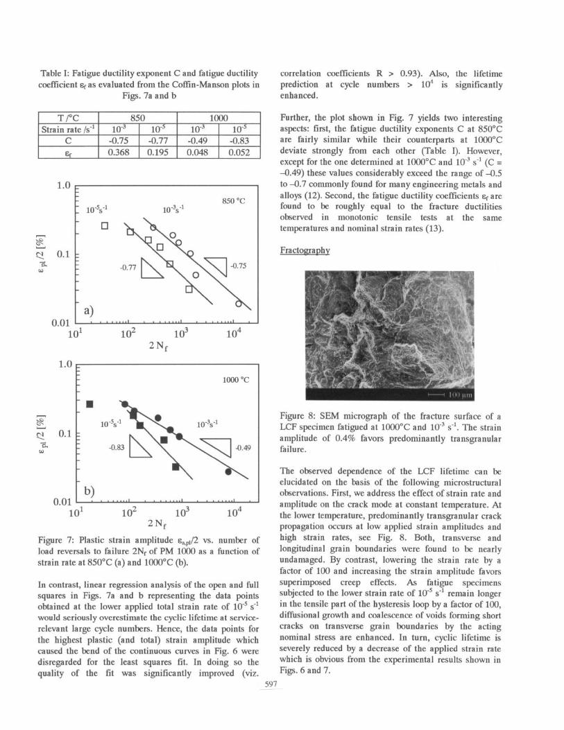
Table I: Fatigue ductility exponent C and fatigue ductility correlation coefficients R > 0.93). Also, the lifetime coefficient of as evaluated from the Coffin-Manson plots in prediction at cycle numbers > lo4 is significantly
Figs. 7a and b enhanced.
T/Y Strain rate /s-l
C F.
850 1000 10” 1o-5 10-j 1o-5
-0.75 -0.77 -0.49 -0.83 0.368 0.195 0.048 0.052
t ) a
850 -2
-0.77 R O
\
o \I -0.75
loo0 “C I
n
0.1 1
0.01 b) I , . . . ..,.I . . . . . . ..I *
lo1 lo2 lo3 lo4 2Nf
Figure 7: Plastic strain amplitude ~+/2 vs. number of load reversals to failure 2Nr of PM 1000 as a function of strain rate at 850°C (a) and 1000°C (b).
In contrast, linear regression analysis of the open and full squares in Figs. 7a and b representing the data points obtained at the lower applied total strain rate of lo5 s-l would seriously overestimate the cyclic lifetime at service- relevant large cycle numbers. Hence, the data points for the highest plastic (and total) strain amplitude which caused the bend of the continuous curves in Fig. 6 were disregarded for the least squares fit. In doing so the quality of the fit was significantly improved (viz.
Further, the plot shown in Fig. 7 yields two interesting aspects: first, the fatigue ductility exponents C at 850°C are fairly similar while their counterparts at 1000°C deviate strongly from each other (Table I). However, except for the one determined at 1000°C and 10” s-l (C = -0.49) these values considerably exceed the range of -0.5 to -0.7 commonly found for many engineering metals and alloys (12). Second, the fatigue ductility coefficients sr are found to be roughly equal to the fracture ductilities observed in monotonic tensile tests at the same temperatures and nominal strain rates (13).
Fractography
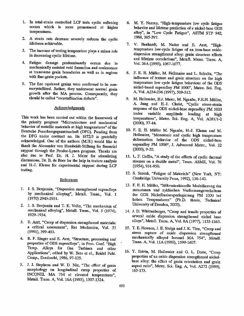
Figure 8: SEM micrograph of the fracture surface of a LCF specimen fatigued at 1000°C and 10” s-l. The strain amplitude of 0.4% favors predominantly transgranular failure.
The observed dependence of the LCF lifetime can be elucidated on the basis of the following microstructural observations. First, we address the effect of strain rate and amplitude on the crack mode at constant temperature. At the lower temperature, predominantly transgranular crack propagation occurs at low applied strain amplitudes and high strain rates, see Fig. 8. Both, transverse and longitudinal grain boundaries were found to be nearly undamaged. By contrast, lowering the strain rate by a factor of 100 and increasing the strain amplitude favors superimposed creep effects. As fatigue specimens subjected to the lower strain rate of 10m5 s-l remain longer in the tensile part of the hysteresis loop by a factor of 100, diffusional growth and coalescence of voids forming short cracks on transverse grain boundaries by the acting nominal stress are enhanced. In turn, cyclic lifetime is severely reduced by a decrease of the applied strain rate which is obvious from the experimental results shown in Figs. 6 and 7.
597

Finally, it should be pointed out here that these observations on fatigue fracture coincide nicely with earlier reports (3-5,14,15) on creep of ODS nickel-base alloys like MA 754 and MA 6000. In particular, a mixed (inter- and transgranular) mode of failure was found by Singer and Arzt in MA 6000 for GAR values of around 10 as also determined for PM 1000 in the present investigation.
Figure 9: Optical micrograph of the longitudinal plane of a LCF specimen fatigued at 850°C to about 90% of cyclic lifetime. The strain rate of lo-’ s-l and the strain amplitude of 0.7% favor void formation and coalescence at transverse grain boundaries.
Figure 10: SEM micrograph of the fracture surface of a LCF specimen fatigued at 1000°C. As compared to Fig. 8, the lower strain rate of lo-’ s-l and the strain amplitude of 0.7% favors intergranular failure.
At a later stage of fatigue, i.e. prior to final failure, there is pronounced internal necking which includes separation of longitudinal grain boundaries. Fig. 9 gives a representative view on this scenario obtained for a specimen fatigued to about 90% relative lifetime with a large strain amplitude of 0.7% at the lower strain rate of lo-’ s-l. Obviously, the strong damage present in Fig. 9 may also explain the deviation of the data points at the largest strain amplitude of 0.7% in the Coffin-Manson lifetime prediction for the strain rate of lo-’ s-l (see Figs. 7a and b). From the damage scenario displayed in Fig. 9 a mixed mode of trans- and intergranular failure should be expected. Fig. 10 supports this conclusion revealing mainly intergranular failure for a specimen fatigued to final failure under the same deformation conditions as that shown in Fig. 9.
400 urn
Figure 11: Optical micrograph (non-etched) of the longitudinal plane of a specimen fatigue deformed at lOOO”C, strain rate lo-’ s-l, strain amplitude 0.3%.
Figure 12: Optical micrograph of the longitudinal plane of a specimen fatigue deformed to about 25% relative lifetime. Deformation conditions: temperature lOOO”C, strain rate 10” s-l, strain amplitude 0.4%.
In contrast to the effect of a strain rate decrease the influence of a temperature change on cyclic lifetime is of minor importance. In essence, Figs. 6 and 7 demonstrate for both strain rates applied a rather marginal further lifetime reduction. We believe this tendency to be caused by the accelerated oxidation on the surface of the samples. A typical example for this is shown in Fig. 11. As expected the mean thickness of the oxide layer was found to be significantly increased at the higher deformation temperature thus giving rise to a higher probability for
598

crack initiation from the specimen surface due incompatibilities between substrate and oxide.
to strain
Figure 13: (100) pole figure of a fine-grained section of PM 1000 (SEM and EBSD). The squares indicate the orientations of the coarse elongated recrystallized grains whereas the circles represent the orientations of the fine grains. rl and r2 denote two orthogonal radial directions in cross-section of the round bar.
Figure 14: Grey-scale image of the grain structure corresponding to Fig. 13.
While Figs. 8 to 11 elucidate the damage state of PM 1000 subjected at final failure, Fig. 12 shows that internal damage already occurs relatively early in fatigue life. In particular, the sample prepared for optical microscopy in Fig. 12 was taken from a test interrupted after around 25% relative life, i.e. still in the region of stabilized cyclic deformation (Fig. 4a). Thorough metallographic preparation and inspection of several specimens interrupted in the saturation state prior to failure revealed (i) that the voids present in Fig. 12 were not artefacts from the grinding and polishing and (ii) that they were former positions of fine equiaxed grains with a diameter of 10 to 20 pm. These grains were found to be mainly situated in pockets along longitudinal grain boundaries of the coarse recrystallized grains. In the present heat these equiaxed grains occupy about 2% of the area1 fraction of the longitudinal plane. Both, the mean diameter as well as the
area1 fraction are in quantitative agreement with the results on Inconel MA 754 reported by Stephens and Nix
(9
Closer SEM examination of the grain orientation by EBSD proved these fine grains to be randomly distributed. Figures 13 and 14, respectively, show a stereographic projection of a (100) pole figure and the corresponding grey-scale image of the grain structure of a fine-grained region of the longitudinal plane in the non-deformed state. Besides the peaks of the coarse elongated grains (squares in Fig. 13) which are centered around the (100) poles a random distribution of the peaks resulting from the fine grains (circles) is observed. This result is in obvious contradiction to the observation of Stephens and Nix (5) who believed the fine grains to be recrystallized grains which were impeded in their growth by high local particle and inclusion concentrations. Though the presence of inclusions next to fine grains in PM 1000 was confirmed by Estrin et al. (16) which supports the assumption of grain growth impedement, we rather conclude from our observations that fine grains have undergone normal growth not preceded by recrystallization. Hence, we suggest to call them “recrystallization defects”.
Considering a grain assembly with pockets of small equi- axed grains aligned between coarse grains elongated in longitudinal direction (Fig. 12) to be strained parallel during low cycle fatigue, it is conceivable that stresses arise between differently oriented grains due to plastic incompatibilities at the grain boundaries. These incompatibilities may originate from the experimentally verified anisotropy of the elastic constants in PM 1000 (10) which gives rise to different plastic strain amplitudes during total strain controlled LCF of differently textured PM 1000 crystals (8,9). Hence, the grain boundaries between the fine grains themselves as well as between fine and coarse grains can act as stress concentrator and become potential sites for void formation (Fig. 12). Consequently, the load-bearing cross-sectional area of the fatigue specimens is reduced and internal damage is initiated. It should be pointed out here that this effect occurs irrespective of whether the grain boundaries of the coarse elongated grains follow the extrusion direction quite closely or not. However, it is amplified in the case of fine grain pockets aligned along grain boundaries inclined at an angle with the extrusion direction.
Conclusions
The investigation of the high temperature LCF behavior of a powder-metallurgical ODS nickel-base superalloy and, in particular, the comparison with the creep behavior reported in the literature yields the following main conclusions:
599
1. In total-strain controlled LCF tests cyclic softening occurs which is more pronounced at higher temperatures.
2. A strain rate decrease severely reduces the cyclic lifetimes achievable.
3. The increase of testing temperature plays a minor role in decreasing cyclic lifetime.
4. Fatigue damage predominantly occurs due to mechanically assisted void formation and coalescence at transverse grain boundaries as well as in regions with fine-grain pockets.
5. The fine equiaxed grains were confirmed to be non- recrystallized. Rather, they underwent normal grain growth after the MA process. Consequently, they should be called “recrstallization defects”.
Acknowledgments
This work has been carried out within the framework of the priority program “Microstructure and mechanical behavior of metallic materials at high temperatures” of the Deutsche Forschungsgemeinschaft (DFG). Funding from the DFG under contract no. He 1872/3 is gratefully acknowledged. One of the authors (M.H.) would like to thank the Alexander von Humboldt-Stiftung for financial support through the Feodor-Lynen program. Thanks are also due to Prof. Dr. H. J. Maier for stimulating discussions, Dr. B. de Boer for the help in texture analysis and H.-J. KIauss for experimental support during LCF testing.
References
1. J. S. Benjamin, “Dispersion strengthened superalloys by mechanical alloying”, Metall. Trans., Vol. 1 (1970) 2943-2951.
2. J. S. Benjamin and T. E. Volin, “The mechanism of mechanical alloying”, Metall. Trans., Vol. 5 (1974), 1929-1934.
3. E. Arzt, “Creep of dispersion strengthened materials: a critical assessment”, Res Mechanica, Vol. 31 (1991), 399-453.
4. R. F. Singer and E. Arzt, “Structure, processing and properties of ODS superalloys”, in Proc. Conf. ?/I&h Temp. Alloys for Gas Turbines and other Applications“, edited by W. Betz et al., Reidel Publ. Comp., Dordrecht, 1986,97-125.
5. J. J. Stephens and W. D. Nix, “The effect of grain morphology on longitudinal creep properties of INCONEL MA 754 at elevated temperatures”, Metall. Trans. A, Vol. 16A (1985), 1307-1324.
6. M. Y. Nazmy, “High-temperature low cycle fatigue behavior and lifetime prediction of a nickel-base ODS alloy”, in “Low Cycle Fatigue”, ASTM STP 942, 1988,385-397.
7. V. Banhardt, M. Nader and E. Arzt, “High- temperature low-cycle fatigue of an iron-base oxide- dispersion strengthened alloy: grain structure effects and lifetime correlations”, Metall. Mater. Trans. A, Vol. 26A (1995), 1067-1077.
8. F. E. H. Mtiller, M. Heilmaier and L. Schultz, “The influence of texture and grain structure on the high temperature low cycle fatigue bchaviour of the ODS nickel-based superalloy PM lOOO”, Mater. Sci. Eng. A, Vol. A234-236 (1997), 509-512.
9. M. Heilmaier, H.J. Maier, M. Nganbe, F.E.H. Miiller, A. Jung and H.-J. Christ, “Cyclic stress-strain response of the ODS nickel-base superalloy PM 1000 under variable amplitude loading at high temperatures”, Mater. Sci. Eng. A, Vol. A281/1-2 (2000), 37-44.
10. F. E. H. Miiller M. Nganbe, H.-J. KIauss and M. Heilmaier, “Monotonic and cyclic high temperature deformation behavior of the ODS nickel-base superalloy PM lOOO“, J. Advanced Mater., Vol. 32 (2000), 9-20.
11. L. F. Coffin, “A study of the effects of cyclic thermal stresses on a ductile metal”, Trans. ASME, Vol. 76 (1954), 931-950.
12. S. Suresh, “Fatigue of Materials” (New York, NY: Cambridge University Press, 1992), 136-140.
13. F. E. H. Miiller, “Mikrostrukturelle Modellierung des monotonen und zykbschen Verformungsverhaltens der ODS Nickelbasissuperlegierung PM 1000 bei hohen Temperaturen” (Ph.D. thesis, Technical University of Dresden, 2000).
14. J. D. Whittenberger, “Creep and tensile properties of several oxide dispersion strengthened nickel base alloys”, Metall. Trans. A, Vol. 8A (1977), 1155-1163.
15. T. E. Howson, J. E. Stulga and J. K. Tien, “Creep and stress rupture of oxide dispersion strengthened mechanically alloyed Inconel MA 754”, Metall. Trans. A, Vol. 11A (1980), 1599-1607.
16. Y. Estrin, M. Heilmaier and G. L. Drew, “Creep properties of an oxide dispersion strengthened nickel- base alloy: the effect of grain orientation and grain aspect ratio”, 163-173.
Mater. Sci. Eng. A, Vol. A272 (1999),