the effect of temperature on cement slurry using fluid ...08)/r0608136151.pdfamerican journal of...
TRANSCRIPT

American Journal of Engineering Research (AJER) 2017
American Journal of Engineering Research (AJER)
e-ISSN: 2320-0847 p-ISSN : 2320-0936
Volume-6, Issue-8, pp-136-151
www.ajer.org Research Paper Open Access
w w w . a j e r . o r g
Page 136
The Effect of Temperature on Cement Slurry Using Fluid Loss
Additive
Oloro John Faculty of Engineering Delta State University, Abraka, Delta State Petroleum and Gas Engineering Department
Corresponding Author: Oloro John
ABSTRACT: Fluid losses are one of the most severe problems encountered in well cementing. It occurs when
the formation pressure is lower than the hydrostatic pressure. It can also occur when the fluid comes in contact
with a permeable or fractured zone. Thus the use of various fluid loss control additive in cementing operations .
This study is to determine the effect of temperature on cement slurry using fluid loss control additive. The
filtration properties of the cement slurry were analysed at 820F to 176 °F temperature range with 10g to 30g of
various fluid loss control additive (FLCA) concentration. Results shows that cement slurry responded
differently to fluid loss control additive at various temperatures, and an increase in temperature caused a
decrease in the filtrate volume. From the t-test carried out, the result shows that there is significant difference
between the various fluid loss control additives.
----------------------------------------------------------------------------------------------------------------------------- ----------
Date of Submission: 17-09-2016 Date of acceptance: 14-08-2017
--------------------------------------------------------------------------------------------------------------- ------------------------
I. INTRODUCTION Additives are substances that are added to cement slurry in order to improve its quality and properties.
During cementing operation as cement slurry is pumped into the wellbore, some of its characteristics and
properties can be affected by temperature and other additives these property includes the following compressive
strength, setting time, viscosity, cement filtration, permeability, heat of hydration, flow properties and yield
point. Additive is an important factor that significantly affects the properties of cement. There are many
additives used in cement industry. The additives have different functions such as denser, retarder, and
viscosifier. In an attempt to obtain appropriate cement, a right additive with an appropriate quantity should be
added on the cement.
Fluid loss is the leakage of the liquid phase of drilling fluid, slurry or treatment fluid containing solid
particles into the formation matrix. Fluid loss control additives are used to maintain consistent fluid volume
within cement slurry to ensure the slurry performance properties remain within acceptable range. These are used
to combat mud loss in the reservoir formation which can cause problems during drilling. There are different
types of fluid loss control additives but this work is limited to the use of starch, CMC, PAC, and XC-
POLYMER.
The aim of this study is to determine effect of temperature on cement slurry using fluid loss additives.
The objectives are as follow;
To determine the behaviour of the additives at different temperature.
To determine the best fluid loss control additives.
II. HISTORY OF CEMENT In a more general sense of the word “cement” is a binder, a substance that sets and hardens
independently, and can bind other materials together. The word cement traces to the Romans, who used the term
opus caementicium to describe masonry resembling modern concrete that was made from crushed rock with
burnt lime as binder. The volcanic ash and pulverized brick additives that were added to the burnt lime to obtain
a hydraulic binder were later referred to as cementum, cimentum, cament and cement. It is uncertain were it
was first discovered that a combination of hydrated non hydraulic lime and a pozzolan produces hydraulic
mixture, but concrete made from such mixture was first used by the ancient Macedonians. Three century later on
a large scale by roman engineers they used both natural pozzolan (that is a light colour of volcanic ash

American Journal of Engineering Research (AJER) 2017
w w w . a j e r . o r g
Page 137
resembling pozzolan were used in making water resistant cement) and artificial pozzolan (ground bricks or
pottery).
CEMENTATION The basic principle of oil well cementing is the process of displacing cement slurry down the casing tubing or in
the annular space.
TYPES OF CEMENTATION 1. Primary cementation: Primary cementing is the cementing operation performed immediately after the
casing has been run down hole. This is accomplished by pumping cement slurry down the entire length of
casing, out the bottom joint, and up into the annular space. The cement is then allowed to set before drilling is
resumed or well is completed. It is carried out in the process of drilling a well. The main objectives of primary
cementing are to seal the annulus and to obtain zonal isolation. The latter is accomplished if cement in the
annulus prevents the flow of formation fluids (Suman et al., 1977). In primary cementing, the object is to place
a continuous sheath or band of cement around the pipe which extends without channels or voids outward to the
formation face. The primary cementing process proceeds as follows; a new section of the well is drilled. The
drill pipe is removed from the wellbore, leaving drilling mud inside the wellbore. A steel tube (casing or liner) is
inserted into the wellbore, typically leaving a gap of 2 cm between the outside of the tube and the inside of the
wellbore, i.e., the annulus. The tubing is inserted in sections of length .10 m each. At certain points, centralizers
are fitted to the outside of the tube, to prevent the heavy steel tubing from slumping to the lower side of the
wellbore. Once the tube is in place, with drilling mud on the inside and outside, a sequence of fluids are
circulated down the inside of the tubing reaching bottom-hole and returning up the outside of the annulus.
Typically, a wash or spacer fluid is pumped first, followed by one or more cement slurries. The rheology and
densities of the spacer and cement slurries can be designed so as to aid in displacement of the annulus drilling
mud, within the constraints of maintaining well security. The fluid volumes are designed so that the cement
slurries fill the annular space to be cemented. Drilling mud follows the final cement slurry to be pumped and the
circulation is stopped with a few meters of cement at the bottom of the inside of the casing and the cement is
allowed to set. The final part of cement inside the tubing is drilled out as the well proceeds (Bittleston et al.,
2004).
Secondary cementation: carried out to remedy deficiencies done in primary cementing or alter the well
completion for production.
CEMENT MANUFACTURING PROCESSES
Cement is a mixture of calcium compound that has been finely grounded. They are produced from limestone
and clay (an addition of aluminium and iron oxide is added when necessary). The materials are then heated to a
temperature ranging from 2600o F to 2800
oF in a rotary kiln. The resulting clinker is grounded with controlled
amount of gypsum into cement.
TYPES OF CEMENT
1. Portland cement; Portland Cements are used for well cementing throughout the world (Dilullo, et al.,
1994). This is the commonly used type of cement; they are finely grounded mixture of carbon compounds. They
are made from limestone (or other high calcium carbonate materials) and clay or shale. It is produced by
partially fusing powdered blends composed of limestone well materials like clay shales, blast funnel slag,
siliceous sands, iron ore and pyrite cylinders. These blends may be considers to be mixture of the oxides of
calcium (CaO, Al2O3, SiO2, MgO, Fe2O3, K2O, Na2O).
These oxides when heated in a rotary kiln to a temperature range between 2600o-2800
o F combine to form
calcium silicate and aluminium commonly referred to as a clinker that can react with water to form a hydrated
product with cementiceous properties.
The compound principally formed in the burning process and their properties are
Tricalcium silicate(C3S);it is a major compound in most cement and principle strength producing material
Tricalcium Aluminate (C3A);it promotes rapid hydration and controls the initial set and thickening time .it
affects the susceptibility of cement to sulphate attack.
Dicalcium silicate (C2S); It is a slow hydrating compound and account for the gradual gain in strength
which occur over an extended period.
2. Pozzolanic or pozzolan-lime cement ;It is a type of cement use for primary cementing wells with
temperature above 140 degree F .pozzolan lime cement is a mixture of siliceous materials that is either natural
such as volcanic particles or artificial such as fly ash, hydrated lime, a small amount of calcium dioxide and
water . The siliceous material increases the strength and lowers the permeability of the cement. Pozzolan-lime
cement is light in weight, economical and easily retarded.
American Journal of Engineering Research (AJER) 2017
w w w . a j e r . o r g
Page 138
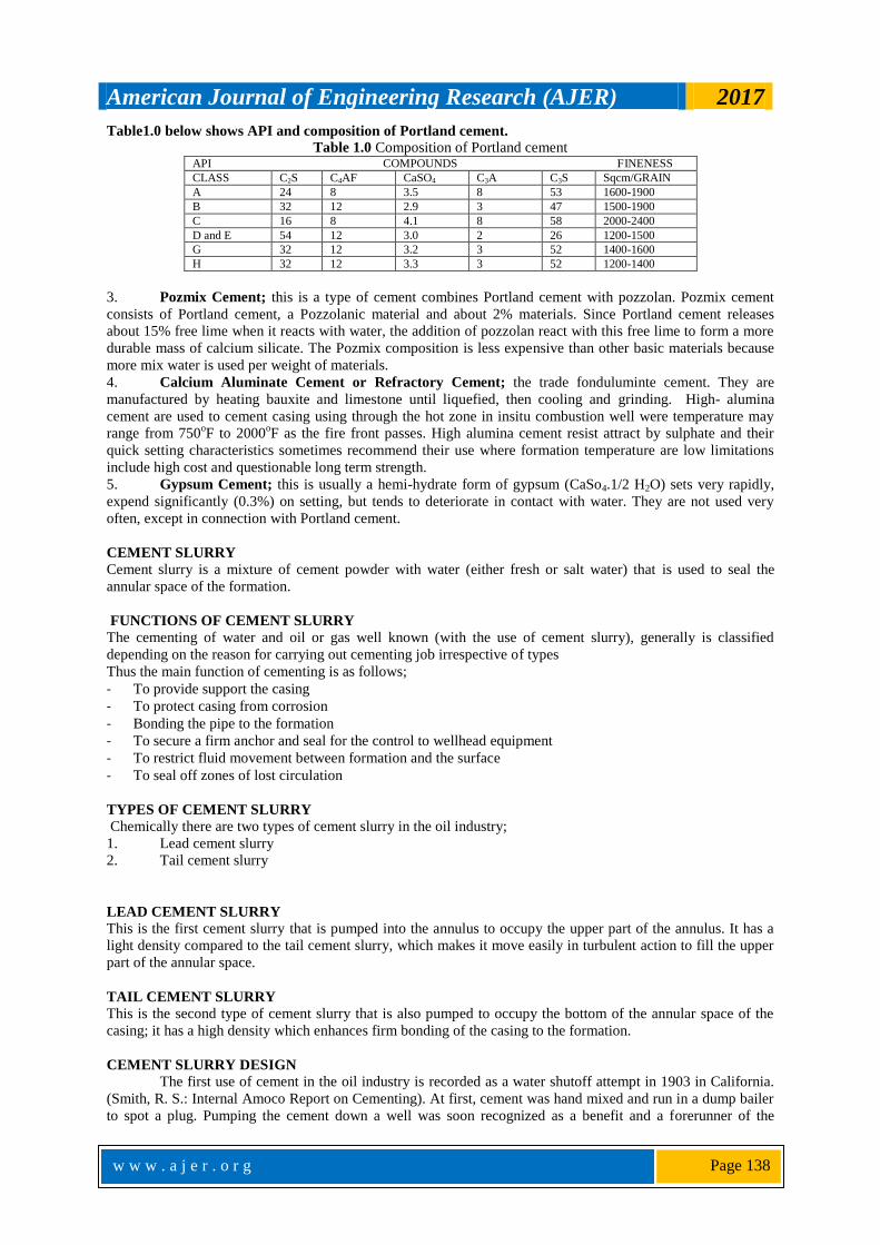
Table1.0 below shows API and composition of Portland cement.
Table 1.0 Composition of Portland cement API COMPOUNDS FINENESS
CLASS C2S C4AF CaSO4 C3A C3S Sqcm/GRAIN
A 24 8 3.5 8 53 1600-1900
B 32 12 2.9 3 47 1500-1900
C 16 8 4.1 8 58 2000-2400
D and E 54 12 3.0 2 26 1200-1500
G 32 12 3.2 3 52 1400-1600
H 32 12 3.3 3 52 1200-1400
3. Pozmix Cement; this is a type of cement combines Portland cement with pozzolan. Pozmix cement
consists of Portland cement, a Pozzolanic material and about 2% materials. Since Portland cement releases
about 15% free lime when it reacts with water, the addition of pozzolan react with this free lime to form a more
durable mass of calcium silicate. The Pozmix composition is less expensive than other basic materials because
more mix water is used per weight of materials.
4. Calcium Aluminate Cement or Refractory Cement; the trade fonduluminte cement. They are
manufactured by heating bauxite and limestone until liquefied, then cooling and grinding. High- alumina
cement are used to cement casing using through the hot zone in insitu combustion well were temperature may
range from 750oF to 2000
oF as the fire front passes. High alumina cement resist attract by sulphate and their
quick setting characteristics sometimes recommend their use where formation temperature are low limitations
include high cost and questionable long term strength.
5. Gypsum Cement; this is usually a hemi-hydrate form of gypsum (CaSo4.1/2 H2O) sets very rapidly,
expend significantly (0.3%) on setting, but tends to deteriorate in contact with water. They are not used very
often, except in connection with Portland cement.
CEMENT SLURRY
Cement slurry is a mixture of cement powder with water (either fresh or salt water) that is used to seal the
annular space of the formation.
FUNCTIONS OF CEMENT SLURRY
The cementing of water and oil or gas well known (with the use of cement slurry), generally is classified
depending on the reason for carrying out cementing job irrespective of types
Thus the main function of cementing is as follows;
- To provide support the casing
- To protect casing from corrosion
- Bonding the pipe to the formation
- To secure a firm anchor and seal for the control to wellhead equipment
- To restrict fluid movement between formation and the surface
- To seal off zones of lost circulation
TYPES OF CEMENT SLURRY
Chemically there are two types of cement slurry in the oil industry;
1. Lead cement slurry
2. Tail cement slurry
LEAD CEMENT SLURRY
This is the first cement slurry that is pumped into the annulus to occupy the upper part of the annulus. It has a
light density compared to the tail cement slurry, which makes it move easily in turbulent action to fill the upper
part of the annular space.
TAIL CEMENT SLURRY
This is the second type of cement slurry that is also pumped to occupy the bottom of the annular space of the
casing; it has a high density which enhances firm bonding of the casing to the formation.
CEMENT SLURRY DESIGN
The first use of cement in the oil industry is recorded as a water shutoff attempt in 1903 in California.
(Smith, R. S.: Internal Amoco Report on Cementing). At first, cement was hand mixed and run in a dump bailer
to spot a plug. Pumping the cement down a well was soon recognized as a benefit and a forerunner of the

American Journal of Engineering Research (AJER) 2017
w w w . a j e r . o r g
Page 139
modern two-plug method was first used in 1910 (Smith, R). The plugs were seen as a way to minimize mud
contact with the cement. Although both mechanical and chemical improvements have been made in the
cementing process, the original plug concept is still valid. Cement design includes the selection of additives and
equipment to remove mud and properly place and evaluate the cement. The cement design depends upon the
purpose of the cementing operation. The initial cement is usually to fill the annular space between the casing
and the hole from the casing shoe to the surface or a point several hundred feet above the zone that must be
isolated. The first cement job is called primary cementing and its success is absolutely critical to the success of
subsequent well control and completion operations. When a primary cement job fails to completely isolate the
section of interest, repair of the cement job must be done before drilling can proceed. These repair steps are
covered by the collective label of squeeze cementing. In a squeeze job, cement is forced into the zone through
perforations, ports in tools, hole produced by corrosion, or through the clearance between casing overlap liners
or strings. Although squeeze cementing has become commonplace, it is expensive and its use can be curtailed
through Improved primary cementing procedures.
Micro fine cement application for repair job requires the mixing of cement into water for making slurry
to be pumped at the damage zone and kept under pressure to allow the maximum penetration of the fluid slurry
into the micro fracture for sealing off cracks completely. And the important parameters are fluid loss control,
thickening time and dispersion. Fluid loss control in oil well cement slurry is very important particularly against
permeable zone. Excessive fluid loss may allow dehydration of slurry resulting in nodes in front of penetration,
which may block the flow of slurry into channels but for Portland cement. It forms a colloidal type of
suspension which can penetrate into channels in the form of cement solution and can acquire early strength.
Design of cement slurry for developing high early age CS for oil well cement is the first priority for oil well
cement (Gino di and Phil, 2000). The recommendation practices according to API specification prepared cement
slurry for oil well require minimum strength for any well bore operation is 500 psi in 24 h at Bottom hole static
temperature. Also minimum 500 psi for 8 h and 1000 psi for 24 h (Samsuri and Yeo, 2000).
High temperature gives a sensitive effect to the cement slurry, especially to the thickening time. It reduces the
thickening time which could set the cement quicker compared to average temperature wells. Cement physical
and chemical behaviour changes significantly at elevated temperatures. Cementing in high temperature
environment is encountered in three principal types of wells; deep oil and gas well, geothermal wells, and
thermal recovery wells (Nelson 2006).
2.1 API CLASSIFICATION OF CEMENT Class A: For use from surface to 6000 ft (1830 m) depth, when special properties are not required.
Class B: For use from surface to 6000 ft (1830m) depth, when conditions require moderate to high surface
resistance.
Class C: For use from surface to 6000 ft (1830 m) depth, when conditions require high early strength.
Class D: For use from 6000 ft to 10,000 ft depth (1830 m to 3050 m), under conditions of high temperatures and
pressures.
Class E: For use from 10,000 ft to 14,000 ft depth (3050 m to 4270 m), under conditions of high temperature
and pressures.
Class F: For use from 10,000 ft to 16,000 ft depth (3050 m to 4880 m), under conditions of extremely high
temperatures and pressures.
Class G: Intended for use as basic cement from surface to 8000 ft (2440 m) depth, Can be used with
accelerators and retarders to cover a wide range of well depths and temperatures.
Class H: Basic cement for use from surface to 8000 ft (2440 m) depth as manufactured. It can be used with
accelerators and retarders to cover a wider range of well depths and temperatures.
Class J: Intended for use as manufactured from 12,000 ft to 16,000 ft (3600 m to 4880 m) depth under
conditions of extremely high temperatures and pressures. It can be used with accelerators and retarders to cover
a range of well depths and temperatures.
FLUID LOSS
Fluid loss is one of the problems related to the drilling operation that will lead to the formation damage.
It occurs when the formation pressure is lower than the hydrostatic pressure, thus let the invasion of the
formation fluid taking place into the wellbore. Fluid loss is the leakage of the liquid phase of drilling fluid,
slurry or treatment fluid containing solid particles into the formation matrix. Fluid loss from drilling mud during
drilling process of borehole occurs when the drilling mud is flowed to the bottom of borehole. Difficulties in
handling and costly are those challenges faced today by operators.
Loss or filtration can occur under static condition (e.g. during tripping) or dynamic (when mud is circulating in
the hole). (Taiwo A, et al, 2011).

American Journal of Engineering Research (AJER) 2017
w w w . a j e r . o r g
Page 140
TROUBLES CAUSED BY FLUID LOSS
Fluid loss can cause several troubles. (Ismail I, et al, 1997)
1. Invasion of filtrate may form a reduced permeability zone around the wellbore and may results in lower
production rate
2. Filtrate may penetrate shale sections of the formation and cause swelling and subsequently sloughing into
the wellbore which could lead to the pipe sticking problem.
FLUID LOSS DETERMINATION The filtration or wall-building property of a mud is determined by means of a filter press. The test
consists of determining the rate at which fluid is forced through the filter paper. The test is run under specified
conditions of time, temperature and pressure. However, when subjected to high temperatures and pressures, the
physical and chemical behaviour of Portland-based cement changes significantly. If the materials are not
handled properly during the formulation stage, they can lose mechanical strength and increase permeability.
These changes may lead to isolation loss and, consequently, provide a high risk to the continuation of activities
(Griffith et al., 2004).
FLUID LOSS CONTROL ADDITIVE
In the field of oil drilling, cement slurry is usually used to reinforce the well wall to provide a stable
and safe wellbore (Kelessidis et al. 2009; Kosynkin et al. 2012). To meet the requirements of cementing job,
additives such as fluid loss additive (FLA) are used to improve performance of the cement slurry (Dugonjic´-
Bilic´ et al. 2011). FLA can control the loss of water from the cement slurry to porous formations and thus
prevent the cement slurry from dehydrating. During the past few decades, various FLA including inorganic
granular materials, modified natural polymers and synthetic polymers have been developed (Amani et al. 2012).
Among them, synthetic polymers were widely studied due to satisfactory performance under complicated
formation environment.
Maintaining constant fluid loss in the deep well is necessary to preserve the chemical and physical
characteristic of the cement slurry, especially due to differential pressure on top and bottom hole in a long or
deep well. Also, fluid loss agents need to prevent the development of filter cake that may cause bridging in the
annulus. It would likely occur in long string casing, especially in deep well cement. Narrow clearance between
wellbore and liner causes a fluid loss to be significant. Too much fluid loss may provide space for the gas to get
into the cement slurry in the annulus.
Fluid loss agent is used to prevent early slurry dehydration for HPHT cementing operation. The design
criteria for fluid loss control are linked to dynamic filtration rather than static filtration. Maximum fluid loss
rates for oil wells are 200 ml per 30 minutes and 50 ml per 30 minutes for gas wells (Hartig et al. 1983).
Christian et al. 1976 and Frittella, Babbo and Muffo 2009 mentioned that the limit for fluid loss is 50 ml per 30
minutes. Another study by Dillenbeck and Smith (1997) showed that, for specific gas field, no fluid-loss is
necessary to get a good cement job. Thixotropic cement slurries can give high fluid loss rates, though
dehydration and bridging must be considered (Pour and Moghadasi 2007).
Fluid loss control additives are used to maintain consistent fluid volume within cement slurry to ensure
the slurry performance properties remain within acceptable range.
The additive reduces loss of water from the slurry into the formation, resulting in a better cement job.
The ideal fluid loss additive would be of low cost and have no adverse effects on the performance properties of
cement. For cement slurry to seal the annulus, it must be effectively "placed," then changed from a liquid to a
solid in the annulus.
Most fluid loss additives are water-soluble polymers. These polymers work in conjunction with the
cement particles themselves to lay down a low permeability filter cake which prevents the fluid in the cement
from leaking-off to the formation. The most common fluid loss additives are members of the cellulose family of
polymers. However, cellulose polymers retard the set time and increase the viscosity of cement.
For more than 20 years, fluid loss control agents have been added to oil-well cement slurries and it is
now recognized in the industry that the quality of cementing jobs has significantly improved. As cement is
pumped across a permeable rock surface under pressure, cement filtrate or water is lost or squeezed out of the
cement into the rock. Indeed, it is generally clearly acknowledged that a lack of fluid loss control may be
responsible for primary cementing failures, due to excessive density increase or annulus bridging and that
formation invasion by cement filtrate may be deleterious to the production. Cement-fluid loss must be controlled
to obtain the right rheological properties for placing the cement and to ensure a good cement bond to pipe and
formation. In this study, laboratory test will be conducted to determine the effects of temperature and different
FLCA concentrations on the cement properties. It is therefore imperative that to optimize a cement slurry design
to meet up with design objectives and all boundary conditions, the choice of optimum FLCA concentration is
critical.

American Journal of Engineering Research (AJER) 2017
w w w . a j e r . o r g
Page 141
FUNCTIONS OF FLUID LOSS CONTROL ADDITIVES
The primary function of fluid loss control agents in cement slurry design is to form a physical plug which arrests
the fluid loss.
Fluid loss control helps to;
1. Maintain the hole integrity
2. Protect the water sensitive shales
3. Minimize hole washout to achieve better casing cement jobs
4. Reduce fluid loss to protective formation and to maximize formation damage
5. Reduce log analysis problems
TYPES OF FLUID LOSS ADDITIVES
1. POLYANIONIC CELLULOSE (PAC)
A cellulose based fluid loss agent is one of the commonly used fluid loss control agents in drilling mud industry.
In view of the fact that the importation of PAC is costly, there is necessity for less expensive polymers. PAC has
showed a better function in water based mud when it’s combined with a sulfonatic polymer and aged in the
temperature of 300oF.
2. STARCH
They have thermal stability to about 250oF(121
oC). They are subject to bacterial attack unless protected by high
salinity or bactericide.
Starches are carbohydrates of general formula (C6H10O5) n and are deduced from corn, wheat, oats, rice,
potatoes, yucca and similar plants and vegetables. They consist of about 27% linear polymers (Amylase) and
about 75% branched polymer (Amylopetin). The two polymers are intertwined within starch granules. Granules
are insoluble in cold water but soaking in hot water or under stream pressure ruptures their covering and the
polymers hydrate into a colloidal suspension.
This product is pregelatinized starch and has been used in cement slurries for many years. Amylase and
amylopetin are non-ionic polymers that do not interact with electrolyte. Derivatives starches such as
hydroxypropyl and carbon methyl starches ate used in drilling fluid, completion fluids, various brine system as
well as in drilling mud system and in cement slurries. The use of starch causes a minimal increase in viscosity
while effectively controlling fluid loss.
3. PAC-R This is a cost-effective additive to reduce API filtration rate of many water based drilling fluids including
freshwater, seawater, saturated saltwater and solids-free brines, native mud, flocculated mud, inhibited mud and
contaminated systems. PAC-R increases and stabilizes viscosity to improve rheology, well hole cleaning and
suspension property by coating and encapsulating cuttings and solids of drilling fluids. PAC-R is effective over
a wide range of pH environments. It lubricates solids in the system, improves wallcake characteristics and
reduces the potential for stuck pipe.
4. SODIUM CARBOXYMETHYLCELLULOSE (CMC) (CMC) is a modified natural polymer used for filtration control. The structure of CMC is a long-chain
molecule that can be polymerized into different lengths or grades. The material is commonly made in three
grades, each varying in viscosity, suspension and fluid-loss-reduction qualities. The three grades are High-
Viscosity (HV), medium- or regular-viscosity (R), and Low-Viscosity (LV). CMC is an effective fluid-loss
control additive. It works particularly well in calcium treated systems, where it acts to stabilize properties. CMC
is not subject to bacterial degradation and performs well at an alkaline pH. CMC’s effectiveness decreases at
salt concentrations greater than 50,000 mg/l. CMC is subject to thermal degradation at temperatures exceeding
250°F.
The grade of CMC used will depend on which properties are desired. When viscosity as well as low fluid
loss is desired, high- or medium-viscosity CMC is used. Low-viscosity CMC will reduce fluid loss with
minimal increase in the viscosity. Because it is slightly anionic, the addition of small quantities of low-viscosity
CMC may act as a thinner in low-solids, non dispersed muds. Normal concentrations vary with the different
grades, but range from 0.5 to 3.0 lb/bbl, depending on the water chemistry and desired fluid loss.
III. METHODOLOGY MATERIALS
The following materials were used in the course of experiment
Portland cement
Distil Water
Poly anionic Cellulose (PAC-R)
Starch

American Journal of Engineering Research (AJER) 2017
w w w . a j e r . o r g
Page 142
XC Polymer
Carbon methyl cellulose (CMC)
EQUIPMENTS
Filter Press: it is used for measuring filtration and wall-building properties of drilling fluid and cement
slurries. The filtration rate is the fluid loss measured in millilitres at ambient temperature and 100psi (690kpa)
through a special filter press for 30minutes. Wall building properties are shown by thickness and consistency of
the filter cake (the residue) deposited on the filter paper after 30minutes, the filter cake is measured to the closet
1/32In or the nearest millimetre. Figure 1.0a and 1.0b are diagram of Filter Press
Figure 1.0a Filter Press Figure 1.0b Filter Press
Hamilton Beach Multi Mixer: it is a rotating machine used for mixing fluids in preparation for
laboratory tests of mud materials. It has various rotation speeds in per minute. This is shown below.
Figure 2.0 Multi Mixer
Mud Balance: Mud Balance is used to determine density of the fluid. The instrument consists of a
constant volume cup with a lever arm and rider calibrated to read directly the density of the fluid in ppg (water
8.33), pcf (water 62.4), specific gravity (water = 1.0) and pressure gradient in psi/1000 ft. (water 433 psi/1000
ft.). This is shown below.

American Journal of Engineering Research (AJER) 2017
w w w . a j e r . o r g
Page 143
Figure 3.0 Mud Balance
Weighing Balance: This is an instrument for weighing as a beam that is supported freely in the center
and has two parts of equal weight suspended from its end. It is used to measure weight or calculate mass. This is
shown below.
Figure 4.0 Weighing Balance
Measuring Cylinder: A graduated cylinder is glassware used to measure the volume of liquids. This is
shown below.
Figure 5.0 Measuring Cylinders
Compressor: Is a machine that converts energy into potential energy stored in compressed air and it’s
used to pressurize the filter press. This is shown below.
Figure 6.0 Compressor

American Journal of Engineering Research (AJER) 2017
w w w . a j e r . o r g
Page 144
Thermometer
Spatula: this is a utensil with a broad flat, often flexible blade, used for lifting, spreading or stirring. It
could be wooden or metallic in form.
PROCEDURE
A. Neat Cement Slurry Formulation 1. 160g of dry cement was measured using the electronic weighing balance.
2. 200ml of distilled water was measured using a measuring cylinder into the multi mixer cup.
3. Gradually the dry cement was added to the water in the multi mixer cup with the mud mixer connected to a
circuit and turned on to get a homogenous mixture.
4. The formulated cement slurry was placed on the mud balance to weigh the cement slurry density.
B. Filtration Property Determination
5. The filter cell was assembled in the following order;
a) Base cup
b) Rubber gasket
c) Screen
d) A sheet of filter paper
e) Cell body
6. The cell of the filter press was filled with the formulated slurry and secure to the base cap by rotating
clockwise placed within the frame..
7. A dry graduated cylinder was placed under the filtrate tube, on the support to receive the filtrate and then
the relief valve was shut and pressure applied. This was carried out for 30mins.
8. The relief valve was closed and pressure shut. The filtrate value was determined by the volume of filtrate
loss in the graduated cylinder. The filter cell was carefully removed and the filter cake thickness was
measured.
TEST
TEST 1: (STARCH ADDITIVE ON CEMENT SLURRY) AIM: To Determine The Effect of Starch On Cement Slurry At Temperatures 82°F,122°F and 176°F
PROCEDURE 1. 160g of cement was measured using the electronic weighing balance.
2. 10 g, 20g and 30g of starch (additive) was measured using the electronic weighing balance.
3. 200ml of water was measured using the measuring cylinder and poured into a mixer cup agitated and kept
for some minutes.
4. The measured cement was added gradually to the mixture in the mixer cup to get a homogenous mixture.
5. The formulated cement slurry with additive was poured into the cell of the filter press capped and secure to
the frame.
6. A dry graduated cylinder is placed at the bottom to receive the filtrate, the relief valve closed and pressure
is applied for 30mins.
7. Volume of the filtrate taken and recorded also set time of the cement and filter cake thickness.
8. Repeat procedure (3-7) for 20g of starch (additive) at 122°F and 176°F respectively.
TEST 2: (XC-POLYMER ADDITIVE ON CEMENT SLURRY)
AIM: To Determine The Effect Of XC-Polymer On Cement Slurry At Temperatures 82°F,122°F and 176°F
PROCEDURE
160g of cement was measured using the electronic weighing balance
10g, 20g and 30g of Xc-polymer (additive) was measured using the electronic weighing balance.
200ml of water was measured using the measuring cylinder and poured into the mixer cup with the 10g of
additives agitated and kept for some minutes.
The 160g of cement is added gradually into the mud mixer with the mixer cup clapped on it and connect to
a circuit turned on to obtain a homogenous mixture.
The formulated slurry with additive is poured into the filter cup cell and secure to the frame.
A graduated measuring cylinder is placed at the base to receive the filtrate, the volume of the filtrate
recorded also the set time of cement and the cake thickness.
Procedure (3-7) repeated for 20g of additive at 122°F and 176°F respectively.

American Journal of Engineering Research (AJER) 2017
w w w . a j e r . o r g
Page 145
TEST 3: (PAC-R ADDITIVE ON CEMENT SLURRY) AIM: To Determine The Effect Of PAC-R On Cement Slurry At Temperatures 82°F,122°F and 176°F
PROCEDURE
160g of cement was measured using an electronic weighing balance.
200ml of water was measured using a measuring cylinder poured, into the mixer cup.
10g, 20g and 30g of PAC-R (additive) was measuring using an electronic weighing balance.
10g of additive was poured into the mixer cup agitated and kept for some minutes.
The 160 g of cement was gradually added to the mixer cup clapped to the mud mixer connected to a circuit
to get a homogenous mixture.
The formulated slurry was poured to the cell of the filter press capped and secure to the frame.
A graduated measuring cylinder was placed at the base to receive the filtrate.
The relief valve was shut and pressure was applied, the test was carried out for 30mins, the volume of the
filtrate recorded pressure shut and then relief valve opened. The filter cake thickness was recorded also the
set time of cement.
Same procedure (3-7) was carried out for 20g of cement at 122°F and 176°F respectively, result read and
recorded.
TEST 4 :(CMC ADDITIVE ON CEMENT SLURRY) AIM: To Determine the Effect of CMC on Cement Slurry at Temperatures 82°F 122°F and 179°F
PROCEDURE
160g of cement was measured using an electronic weighing balance.
10g, 20g and 30g of CMC (additive) was measured using an electronic weighing balance.
200ml of water was measured using a measuring cylinder and poured in a mixer cup with the 10g of
additive agitated and kept for some minutes.
Gradually the 160g of cement was added to the mixer cup already clamped to the mud mixer connected to a
circuit and turned on to obtain a homogenous mixture.
The formulated cement slurry with additive was poured into the filter press cell capped and secure to the
frame.
A graduated cylinder was placed at the bottom to receive the filtrate, the relief valve was turned on and
pressure was applied.
The test was carryout for 30mins the volume of the filtrate recorded the cake thickness and set time.
Procedure (3-7) is repeated for 20g of additives at 122°F and 176°F respectively same result recorded.
T-TEST OF TWO MEANS FOR INDEPENDENT SAMPLES The T-test or t-distribution was developed by William gusset in 1909 who wrote under the pen name
“student”. The development of this arose when the z-test for testing of hypothesis using statistical analysis.
Hence the t-test will be used in this work to compare between volumes of fluid loss of the various fluid loss
additives.
The t-test of one sample mean will not be demonstrated here because one rarely come across a situation
where a sample mean is compared with a theoretical or population mean. Furthermore, the computation of the t-
ratio for one sample mean is identical with the calculation of the z-ratio for one mean. The difference, however
is that instead of using critical z-ratio to take a decision on H0, critical t-ratios for chosen alpha levels and for
appropriate degrees of freedom are used to reject or accept the null hypothesis.
The common situation encountered in educational and behavioural science researchers is the
comparison of two means (both independent and correlation samples). Comparison of two means for correlated
samples will be presented in the next section. The use of the t-test for two independent samples means require
meeting three assumptions.
1. That the sample measure are a random sample from the population of interest
2. That the parent population be normally distributed (large sample take care of this if the assumptions not yet
met).
3. Homosscedasity, that is, the population variances for the two groups are equal. The first two assumptions
are required for the z-test and the third assumption is needed only for the comparison of the two groups is
assumed, a pooled estimate of the variance is used to estimate the standard error of the difference between
both means.

American Journal of Engineering Research (AJER) 2017
w w w . a j e r . o r g
Page 146
STEPS TO SOLVING T-TEST FOR TWO INDEPENDENT SAMPLES
1. State a hypothesis for the problem
A null hypothesis is stated:
Āx = mean for sample x
Āy = mean for sample y
2. Choose a significant level to test H0 above. α = 0.05 be chosen.
3. Calculate a t-ratio of the differences between the means
a. The means for both samples are first calculated
b. Calculate the sum of squares(SS) for each sample using
c. Calculate the estimated standard error of the difference between the means, using
d. Calculate the t-ratio as
xx
tAA sx
21
e. Obtain the degree of freedom as N1 + N2 -2.
4. Compare the obtained t-ratio with the table t-ratio for df, using a two- tailed test
The use of t-test requires that there is no significant difference between variance of both groups.
PRECAUTIONS
It was ensured that the filter press and pressurizing machine was test run and inspected by the technicians
before usage, so as to avoid leakage and advert injury that can be caused by release of pressurizing fluid.
It was ensured that the filter press was dry and cleaned to avoid contamination of samples.
Pressure was monitored so as not to exceed 100psi.
Ensured pressure was kept constant throughout the 30minutes test period
It was ensured that the pressure supply was shut off when depressurizing, the bleed the system of pressure,
and back out the regulator tee screw
Ensured cell and measuring cylinder were dry before the test started
Avoided error due to parallax when taking readings of the graduated cylinder.
Ensured the use of personal protective equipment
OBSERVATION
Observe pressure for 30mins was 100psi
There was foaming in the cement slurry on addition of CMC and XC-Polymer and they absorbed water.
There was foam in the filtrate of XC-polymer at the end of the 30mins.
There was varying filtrate loss in the samples depending on the FLCA added.
There was varying filter cake thickness, texture of each slurry
IV. RESULT AND DISCUSSION Table2.0 : Fluid Loss and Filter Cake Thickness at 82ºF
ADDITIVES
Properties (NEAT
CEMENT) (STARCH) (XC-POLYMER) (PAC-R) (CMC)
Mud weight (ppg) 11.65 11.65 11.65 11.65 11.65
Filtrate volume(ml) 200 150 19.6 7.5 7
Cake thickness(cm) 2.1 2.4 3.7 5.1 4.5
Table2.0 illustrate fluid loss and Cake thickness at 820F .The result shows that PAC-R has more ability to
reduce fluid loss when used as an additive compared to others as also seen in Fig 7.0 below.
Table 3.0: Results for Fluid Loss and Filter Cake Thickness at 122ºF ADDITIVES
Properties (NEAT
CEMENT) (STARCH) (XC-POLYMER) (PAC-R) (CMC)
Mud weight (ppg) 11.65 11.65 11.65 11.65 11.65
Filtrate volume(ml) 150 135 12.5 5.6 7
Cake thickness(cm) 2.1 2.4 1.5 5 3.1
Table 3.0 illustrate fluid loss and Cake thickness at 1220F .The result shows that PAC-R also has more ability to
reduce fluid loss when used as an additive compared to others at this Temperation.

American Journal of Engineering Research (AJER) 2017
w w w . a j e r . o r g
Page 147
Table4.0 :Results for Fluid Loss and Filter Cake Thickness at 176ºF
ADDITIVES
Properties Neat Cement Starch XC-Polymer PAC-R CMC
Mud weight (ppg) 11.65 11.65 11.65 11.65 11.65
Filtrate volume(ml) 150 140 25 25 15.8
Cake thickness(cm) 2.1 2.6 4 4.5 3.6
Table4.0 illustrate fluid loss and Cake thickness at 1760F .The result shows that PAC-R has the highest cake
thickness as seen in Fig 8.0 and as result it has more ability to reduce fluid loss when used as an additive
compared to others.
Fig 7.0 Fluid loss at 82 0F
Fig 8.0 Cate thickness at 82
0F
Fig 9.0 Effect of temperation on fluid loss

American Journal of Engineering Research (AJER) 2017
w w w . a j e r . o r g
Page 148
Fig 9.0 illustrate effect of temperation on filtrate loss for different additives.The result shows ttat at low
temperation the filtrate loss increases but as the temperation increases the filtrate loss become stable.When
starch has the highest Filtrate loss as shown in the figure above
Fig 10.0 Effect of temperation on Cake thickness
Table 5.0 : Cake Thickness at different Temperation
Additives Neat Cement Starch XC-Polymer Pac-R CMC
Cake Thickness(cm) 82 F 2.1 2.4 3.7 5.1 4.5
Cake Thickness(cm) 122 F 2.1 2.4 1.5 5 3.1
Cake Thickness(cm) 176 F 2.1 2.6 4 4.5 3.6
From the table in 4.1 above it was observed that the slurry weight remains the same for both neat
cement slurry and slurry with additives and increase in concentration of FLCA does not affect the mud density
of the fluid
Neat cement slurry had a higher fluid loss rate as compared with other slurry having additive. Sample E
had lower filtrate volume of 7ml at the end of 30mins as compared to Sample A (200ml) sample B (150ml),
sample C (19.6ml), and sample D (7.5ml). Thus it shows that 82°F sample E is better compared to other sample
due to the reduction of filtrate volume.
Filter cake is a layer of substance formed on a filter paper when the fluid loss test using the filter press
was ended. The result showed that there was a difference in thickness of the filter cake of the cement slurry due
to the difference in FLCA. The measured thickness ranged from 2.1 to 4.5cm. The filter cake consistency of
starch is hard, XC polymer is rubbery, PAC-R is soft and CMC is tough.
Results for Fluid Loss and Filter Cake Thickness at 122ºF
From the table 4.2 it was observed that the slurry weight remains the same for both neat cement slurry
and slurry with additives and increase in concentration of FLCA does not affect the mud density of the fluid.
Neat cement slurry had a higher fluid loss rate as compared with other slurry having additive. Sample
D (PAC-R) had lower filtrate volume of 5.6ml at the end of 30mins as compared to Sample A (150ml) sample B
(135ml), sample C (12.5ml), and sample E (7ml). Thus it shows that at 122°F sample D is better compared to
other sample due to the reduction of filtrate volume.
The result showed that there was a difference in thickness of the filter cake of the cement slurry due to
the difference in FLCA. The measured thickness ranged from 2.1 to 5.0cm. The filter cake consistency of starch
is hard, XC-polymer is rubbery, PAC-R is soft and CMC is tough.
From the table 4.3 was observed that the slurry weight remains the same for both neat cement slurry
and slurry with additives and increase in concentration of FLCA does not affect the mud density of the fluid.
Neat cement slurry had a higher fluid loss rate as compared with other slurry having additive. Sample E
(CMC) had lower filtrate volume of 15.8ml at the end of 30mins as compared to Sample A (150ml) sample B
(140ml), sample C (25ml), and sample D (25ml). Thus it shows that at 178°F sample E is better compared to
other sample due to the reduction of filtrate volume.
The result showed that there was a difference in thickness of the filter cake of the cement slurry due to
the difference in FLCA. The measured thickness ranged from 2.1 to 4.5cm. The filter cake consistency of starch
is hard, XC polymer is rubbery, PAC R is soft and CMC is tough.

American Journal of Engineering Research (AJER) 2017
w w w . a j e r . o r g
Page 149
Table 6.0 A summarised value of neat cement slurry and the various additives
Fig 11.0 Neat Cement Filter cake Fig 12.0 CMT + STARCH Filter Cake
Fig 13.0 CMT + PAC-R Filter Cake Fig 14.0 CMT + XC-POLYMER Filter Cake
Fig 15.0 CMT + CMC Filter Cake
An increase in temperature increases the set time of the cement slurry. When XC polymer was tested at
ambient temperature the filter cake had a set time of 48hrs but at increased temperature the filter cake had a set
time of 36hrs. PAC R at ambient temperature had a set time of 120hrs while at high temperature it had set time

American Journal of Engineering Research (AJER) 2017
w w w . a j e r . o r g
Page 150
of 72hrs. CMC had a set time of 48hrs at ambient temperature while 72hrs at high temperature. STARCH has a
set time of 2hrs for ambient and high temperature.
T-TEST CALCULATION FOR XC-POL AND STARCH SAMPLE
H0: Āx – Ās
Āx = mean for XC-Polymer
Ās= mean for starch
α = 0.10, 0.05, 0.01 are used respectively
Hence: Āx = 19.03333
Ās = 141.6667
Where SS = Sum of square for each sample
N = number of terms
SSx = Sum of square for XC polymer
SSs = Sum of square for starch
SSx
Where = 19.62 + 12.5
2 + 25
2 = 1165.41
N = 3
= (19.6 + 12.5 + 25)2= 57.1
2 = 3260.41
SSx =
SSx =
=
= 78.6067
SSs =
Where = 1502 + 135
2 + 140
2 = 60325
N = 3
= (150 + 135 + 140)2= (425)
2 = 180625
SSs
SSs
= 116.6667
Estimated standard error of the difference between the mean
= 5.704
Calculate T-ratio
=

American Journal of Engineering Research (AJER) 2017
w w w . a j e r . o r g
Page 151
df = N+N-2
=3+3-2 =4
Comparing the obtained t-ratio with table for 4 df.
Obtained t-ratio = 21.49625, table t-ratio (α=0.10, 0.05, 0.01) for df = 1.533, 2.776, 4.604 respectively.
There is a significant difference between XC-POL and Starch in their ability to control fluid loss at the various
temperatures.The same computation was carried out for others and the results are as follow
For XC-POL and PAC-R
There is a no significant difference between XC-POL and PAC-R in their ability to control fluid loss at the
various temperatures.
For XC-POL and CMC
There is a no significant difference between XC-POL and CMC in their ability to control fluid loss at the
various temperatures.
For Starch and CMC
There is a significant difference between Starch and CMC in their ability to control fluid loss at the various
temperatures.
For Starch and PAC-R
There is a significant difference between Starch and PAC-R in their ability to control fluid loss at the various
temperatures.
For CMC and PAC-R
There is a significant difference between CMC and PAC-R in their ability to control fluid loss at various
temperatures.
V. CONCLUSION It is expected that the higher the temperature the lower the volume of filtrate lost, and higher fluid loss
indicates that when cement slurry is pumped into the well, it might require secondary cementing. From the
experiment carried out it showed that the cement slurry responded differently to fluid loss control
additive at various temperature. Increase in temperature caused a decrease in the filtrate volume of neat
cement, starch. While XC-polymer and Pac-R was high at 82°F reduced at 122ºF and increased at 176ºF. For
CMC as temperature increased the filtrate volume became high.
In conclusion fluid loss control additives have been found to provide adequate control in cement slurry
at various temperatures. From the experiment at the various temperatures CMC is considered to be the best
fluid loss additive.
REFERENCE [1]. Suman, G.O. and R.C, Ellis, 1977. World Oil's Cementing Oil and Gas Wells: Including Casing Handling Procedures. Gulf
Publishing Co., Texas, pp: 34
[2]. Nelson E.B. and Guillot D.: “Well Cementing” 2nd edition, 2006.
[3]. Taiwo, A., Joel, O. L., and Kazeem, A. A. (2011) Investigation of Local Polymer (Cassava Starches) as A Substitute for Imported Sample in Viscosity and Fluid Loss Control of Water Based Drilling Mud. ARPN Journal of Engineering and Applied Sciences,
6(12): 43-48.
[4]. Ismail, I., and Idris, A. K. (1997) The Prospect of Utilising Local Starches as Fluid Loss Control Agents in the Petroleum Industry. Proceedings of Regional Symposium on Chemical Engineering. October 13-15. Hyatt Regency, Johor: UTM, 375-386.
[5]. Kelessidis VC, Papanicolaou C, Foscolos A (2009) Application of Greek lignite as an additive for controlling rheological and
filtration properties of water–bentonite suspensions at high temperatures: a review Int J Coal Geol 77:394–400 [6]. Kosynkin DV, Ceriotti G, Wilson KC, Lomeda JR, Scorsone JT, Patel AD, Friedheim JE, Tour JM (2012) Graphene oxide as a high
performance fluid-loss-control additive in water-based drilling fluids. ACS Appl Mater Interface 4:222–227
[7]. Dugonjic´-Bilic´ F, Plank J (2011) Polyelectrolyte complexes from polyethylene imines/acetone formaldehyde sulphite poly-condensates: a novel reagent for effective fluid loss control of oil well cements slurries. J Appl Polym Sci 121:1262–1275
[8]. Amani M, Al-Jubouri M, Shadravan A (2012) Comparative study of using oil-based mud versus water-based mud in HPHT fields.
Adv Pet Explore Dev 4:18–27 [9]. Frittela F., Babbo M.and Muffo A.I.: “Best Practices and Lesson Learned From 15 Years of Experience of Cementing HPHT Wells
in Italy”. SPE/IADC 125175 was prepared for presentation at the SPE/IADC Middle East Drilling Technology Conference &
Exhibition held in Manama, Bahrain, 26-28 October 2009. [10]. Dillenbeck R.L. and Smith J.: “Highly Relaxed Fluid Loss, Surfactant Enhanced Cement Improves Results on Deep Gas Wells”.
SPE 38599 was presented at the SPE Annual Technical Conference and Exhibition, San Antonio, Texas, USA, 5-8 October 1997.
[11]. Pour M.M. and Moghadasi J.: “New Cement Formulation That Solves Gas Migration Problems in Iranian South Pars Field Condition”. SPE 105663 was prepared for presentation at the 15th SPE Middle East Oil & Gas Show and Conference held in
Bahrain International Exhibition Center, Kingdom of Bahrain, 11-14 March 2007.
[12]. Griffith J.E., Lande G, Ravi K., Saasen A., Nodland N.E. and Jordal O.H.: “Foam Cement Engineering and Implementation for Cement Sheath Integrity at High Temperature and High Pressure”. IADC/SPE 87194 was prepared for presentation at the
IADC/SPE Drilling Conference held in Dallas, Texas, U.S.A, 2-4 March 2004.
Oloro John " The Effect of Temperature on Cement Slurry Using Fluid Loss Additive."
American Journal of Engineering Research (AJER) 6.8 (2017): 136-151