the effects of axial restraint in reinforced …demonstrate that the axial compressive load...
TRANSCRIPT

THE EFFECTS OF AXIAL RESTRAINT IN REINFORCED CONCRETE COUPLING
BEAMS
R.C. MALCOLM1, D.K. BULL2,3, R.S. HENRY1, J.M. INGHAM1
1 Department of Civil and Environmental Engineering, University of Auckland, New Zealand 2 Department of Civil and Natural Resources Engineering, University of Canterbury, New
Zealand
3 Holmes Consulting Group, Christchurch, New Zealand
SUMMARY Axial elongation of reinforced concrete (RC) plastic hinges has previously been observed in a range of laboratory experiments, and more recently was observed in several Christchurch buildings following the 2010/2011 Canterbury earthquakes. Axial restraint to plastic hinges is provided by adjacent structural components such as floors as the plastic hinges elongate, which can significantly alter the performance of the plastic hinge and potentially invalidate the capacity design strength hierarchy of the building. Coupling beams in coupled wall systems are particularly susceptible to axial restraint effects due to their importance in the strength hierarchy, the high ductility demands that they experience, and the large stiffness of bounding walls. From computational modelling it has been found that ignoring axial restraint effects when designing coupled walls can result in significantly increased strength, reduced ductility and reduced energy dissipation capacity. The complexity of the topic merits further research to better account for realistic restraint effects when designing coupled walls. INTRODUCTION Reinforced concrete (RC) coupled walls are a common structural system in seismic zones due to their high levels of stiffness and ductility when resisting lateral loads, whilst providing allowance for door and window penetrations. In particular, RC coupled walls are widely used in multi-storey buildings supported by stiff shear cores due to the presence of wall penetrations to allow the core to function as an elevator shaft, as illustrated in Figure 1. The coupling of two walls by means of a ductile coupling beam also provides enhanced ductility and lateral strength capacity when compared to that of two isolated walls. Ductile building performance during design level seismic excitation is dependent upon adherence to capacity design principles that require the isolation of plastic deformation to pre-determined regions in the lateral load resisting system in order to prevent brittle failure of the structure. The design intent of a coupled wall structure is
Figure 1: Example floor plan arrangement of coupled wall shear core building
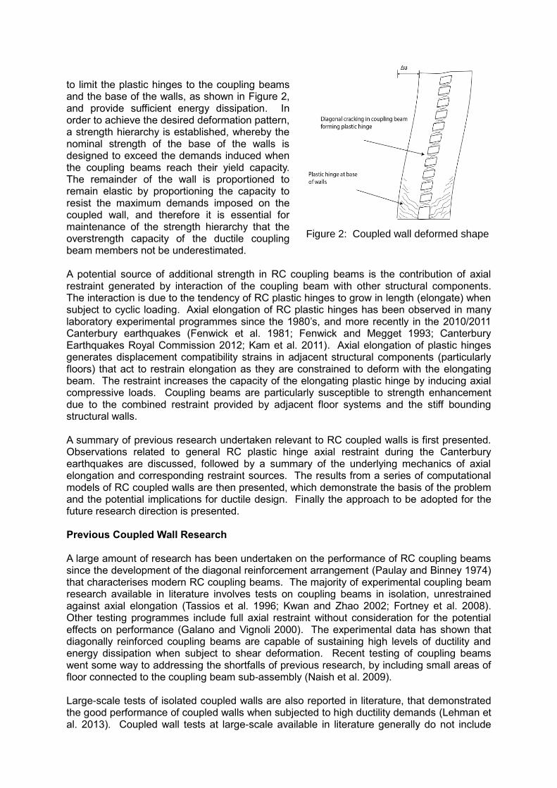
to limit the plastic hinges to the coupling beams and the base of the walls, as shown in Figure 2, and provide sufficient energy dissipation. In order to achieve the desired deformation pattern, a strength hierarchy is established, whereby the nominal strength of the base of the walls is designed to exceed the demands induced when the coupling beams reach their yield capacity. The remainder of the wall is proportioned to remain elastic by proportioning the capacity to resist the maximum demands imposed on the coupled wall, and therefore it is essential for maintenance of the strength hierarchy that the overstrength capacity of the ductile coupling beam members not be underestimated. A potential source of additional strength in RC coupling beams is the contribution of axial restraint generated by interaction of the coupling beam with other structural components. The interaction is due to the tendency of RC plastic hinges to grow in length (elongate) when subject to cyclic loading. Axial elongation of RC plastic hinges has been observed in many laboratory experimental programmes since the 1980’s, and more recently in the 2010/2011 Canterbury earthquakes (Fenwick et al. 1981; Fenwick and Megget 1993; Canterbury Earthquakes Royal Commission 2012; Kam et al. 2011). Axial elongation of plastic hinges generates displacement compatibility strains in adjacent structural components (particularly floors) that act to restrain elongation as they are constrained to deform with the elongating beam. The restraint increases the capacity of the elongating plastic hinge by inducing axial compressive loads. Coupling beams are particularly susceptible to strength enhancement due to the combined restraint provided by adjacent floor systems and the stiff bounding structural walls. A summary of previous research undertaken relevant to RC coupled walls is first presented. Observations related to general RC plastic hinge axial restraint during the Canterbury earthquakes are discussed, followed by a summary of the underlying mechanics of axial elongation and corresponding restraint sources. The results from a series of computational models of RC coupled walls are then presented, which demonstrate the basis of the problem and the potential implications for ductile design. Finally the approach to be adopted for the future research direction is presented. Previous Coupled Wall Research A large amount of research has been undertaken on the performance of RC coupling beams since the development of the diagonal reinforcement arrangement (Paulay and Binney 1974) that characterises modern RC coupling beams. The majority of experimental coupling beam research available in literature involves tests on coupling beams in isolation, unrestrained against axial elongation (Tassios et al. 1996; Kwan and Zhao 2002; Fortney et al. 2008). Other testing programmes include full axial restraint without consideration for the potential effects on performance (Galano and Vignoli 2000). The experimental data has shown that diagonally reinforced coupling beams are capable of sustaining high levels of ductility and energy dissipation when subject to shear deformation. Recent testing of coupling beams went some way to addressing the shortfalls of previous research, by including small areas of floor connected to the coupling beam sub-assembly (Naish et al. 2009). Large-scale tests of isolated coupled walls are also reported in literature, that demonstrated the good performance of coupled walls when subjected to high ductility demands (Lehman et al. 2013). Coupled wall tests at large-scale available in literature generally do not include
Figure 2: Coupled wall deformed shape

realistic floor components and typically only test the lower levels of the coupled wall. There is a significant lack of reported research that captures the behaviour of coupling beams subject to realistic axial restraint, likely due to the need to capture the full wall-floor interaction that implies a large and expensive test setup. Due to the relative ease of capturing large-scale effects in modelling software, it is likely that the majority of the sought-after understanding will need to be developed from interpretation of computational models. OBSERVATIONS MADE FOLLOWING 2010/2011 CANTERBURY EARTHQUAKES
Canterbury earthquakes damage observations are covered extensively in literature, with a brief summary of the observations relevant to RC coupled walls presented herein. The 2010/2011 Canterbury earthquakes caused significant damage to a range of RC buildings in Christchurch, including buildings containing coupled walls. In particular, 224 Cashel St was an RC coupled wall shear core structure which suffered damage during the Canterbury earthquakes. Analysis of the structure for the Canterbury Earthquakes Royal Commission (CERC) suggested that the coupling beams in the shear core sustained demands in excess of their design intent due to the restraining effect of the adjacent floor system as the beams tended to elongate (Canterbury Earthquakes Royal Commission 2012). The analysis conducted for CERC indicated that the actual strength of the coupling beams could have been up to 50% higher than the strength assessed by current design standards due to the restraint provided to the coupling beam. It was concluded in the CERC report that a strength increase of this magnitude could have contributed to the damage observed to the foundations. In addition, analysis of the CTV Building south coupled wall by Compusoft (2012) found that although the behaviour of the coupled wall was assessed as not contributing to the building collapse, the coupled wall was deemed to display higher strength and lower ductility than current design approaches would suggest. The increased strength and reduced ductility anticipated in real structures as compared to current code considerations has been deemed by CERC to require further research.
AXIAL ELONGATION MECHANICS The underlying principles of axial elongation of RC plastic hinges have been explored in a series of experimental programmes in New Zealand since the 1980’s, with reference to conventionally reinforced beams in moment frames (Fenwick et al. 1981; Fenwick and Thom 1982; Fenwick and Megget 1993). Axial elongation of RC plastic hinges was found to be the result of three mechanisms:
Geometric elongation,
Contact stress effect,
Truss action effect. Geometric elongation occurs in all RC sections subject to bending when the cracking moment is exceeded. The cracking of the section causes the neutral axis to move towards the compression zone, and thus the mid-section is subject to tension strain such that the section is observed to elongate. Fenwick and Thom (1982) showed that the magnitude of elongation increases appreciably once the section is subjected to plastic strains, due to the additional contribution of the contact stress effect and the truss action effect. The contact stress effect arises due to the wedging action of aggregate particles that are dislodged in the flexural cracks, causing the cracks to be propped open, thus causing progressive tension strain accumulation when subjected to cyclic loading. The truss action effect arises due to the inclination of the diagonal compression strut aiding in resisting shear in a cracked section, causing the flexural tension force to exceed the flexural compression force for static equilibrium, thus promoting tensile strain accumulation. A more detailed explanation of RC plastic hinge axial elongation has been published by (Fenwick and Megget 1993).

Experimental analysis of unrestrained RC plastic hinges was compiled by Fenwick et al. (2010), to observe the typical elongation behaviour of plastic hinges. As presented in Figure 3, axial elongation tends to increase with increased hinge rotational strain demands, until the elongation reaches a maximum value of the order of 3.5% of beam depth. In addition, testing of RC plastic hinges subject to varying levels of axial force has been used to demonstrate that the axial compressive load appreciably reduces the measured axial elongation (Fenwick and Megget 1993). The restraining effect on an RC plastic hinge has been observed in a range of frame tests including floors where the axial elongation of RC plastic hinges in the perimeter frame was reduced significantly by the presence of stiff floor systems (Fenwick et al. 2005; MacPherson et al. 2005). AXIAL RESTRAINT MECHANISMS Axial restraint to elongating plastic hinges arising in real buildings is inherently complex due to the interaction of structural components and the variety of building configurations possible. A series of experiments undertaken at the University of Auckland and the University of Canterbury on frame-floor systems have shown that the presence of floors connected to elongating moment frame plastic hinges can significantly alter the performance of both components (Matthews 2005; Fenwick et al. 2005; Peng et al. 2011; MacPherson et al. 2005). In addition to extensive damage induced in the flooring systems, the strength enhancement to the plastic hinges was found to be significantly in excess of existing NZS 3101:2006 requirements. The configuration of the precast floor units typically used in New Zealand was also found to have a significant impact on the response of the system. A typical crack pattern from the testing of floor-frame units is presented in Figure 4, demonstrating the distribution of cracks in the floor system. As can be seen from the crack pattern, elongation strains tend to be concentrated at relatively weak ‘fuse’ locations, where stiff pre-stressed floor units are terminated and the topping is generally relied upon to transfer compatibility forces. Examples of these weak fuses, such as those at the ends of the floor units across a transverse beam are shown in Figure 5. Fuses result in a large variation in the restraint force (dependent upon the floor configuration) as the restraint force generated across a fuse is much lower than that generated when no fuses are present, or they are too distant to be activated. Observations made following the Canterbury earthquakes showed that where the floors were subject to elongation strains, a single wide crack tended to open at the location of a weak fuse (Canterbury Earthquakes Royal Commission 2012; Kam et al. 2011). Although the prevalence of cold-drawn mesh or ductile mesh may have acted to concentrate strains (hence result in bar fracture at a single crack) it is likely that even with modern detailing utilising ductile deformed topping bars, the effect of the
Figure 3: Axial elongation measurements of RC plastic
hinges collated (Fenwick et al. 2010)
Figure 4: Typical crack pattern in floor due to
perimeter frame (Fenwick et al. 2005)

fuses will still be significant. This behaviour was seen by Macpherson (2005) who observed large cracks in the topping at the transverse beam location despite using ductile deformed bars for topping reinforcement. In order to assess the floor restraint capacity, it is therefore necessary to understand whether or not the restraint is governed by the capacity of the floor units or the capacity of a fuse. VecTor2 finite element modelling software was selected to generate the deformation pattern for typical floor arrangements as this software provides a good level of accuracy for in-plane stresses in RC members as shown in Figure 6 and Figure 7 (VecTor Analysis Group 2011). VecTor2 is specifically designed for two dimensional finite element modelling of RC members based upon the Modified Compression Field Theory (MCFT). For the precast pre-stressed floor units typical of New Zealand construction, there are three common cases to consider in
(a) Floor plan typical layout of floor fuse (b) Section through transverse beam
Figure 5: Floor fuse layout typical
(a) Units spanning perpendicular to wall (b) Units spanning parallel to wall,
supported on transverse beam Figure 6: VecTor2 model output for typical floor layouts - floor stress (parallel to elongation)
(a) Unit span 15m (b) Unit span 10m
Figure 7: VecTor2 model outputs for typical floor units spanning parallel past coupled wall supported on transverse beams - floor stress (parallel to elongation)
the axial restraint of general plastic hinges. The first case is based upon the floor units spanning perpendicular to the elongation direction. As presented in Figure 6(a), as only topping reinforcement spans across the interface of the units, the capacity of the weak fuse tends to govern the restraint that can be generated by the floor diaphragm. The second case involves floor units which span parallel to the elongation direction, but which are supported on a transverse beam at the wall location, as shown in Figure 5 (b). As presented in Figure 6 (b), the fuse at the transverse beam unit support tends to concentrate strains and hence reduce the ability of the floor to restrain elongation. The third case involves the floor units spanning past the elongating member (coupling beam), which presents the most complex and also critical case for axial restraint. As the floor fuses are located further away from the elongating member, there is potential to activate a much larger restraint force as the precast pre-stressed floor units could potentially activate their full tension capacity, before either failure of the unit, shear transfer failure at the wall-floor interface, or activation of a fuse. As shown in Figure 7, the activation of the fuse depends upon the relative distance of the fuse and the magnitude of elongation. However, modelling has shown that in this case, with floor unit spans of the order of 10-15 m typical of New Zealand precast units and with elongations of the magnitudes anticipated in RC coupling beams, the fuses tend not to activate and thus a large restraint force is generated by the floor units. Fenwick et al. (2006) present a method for calculating the restraint force in this case, but the method relies on an assumption of an ‘effective floor width’ which is difficult to quantify (Fenwick et al. 2006). More research is needed in this area to better characterise the magnitude of restraint force in the case of units spanning past an elongating member. In addition to restraint provided by floor diaphragms, axial restraint to coupling beams can also be generated by the structural walls which bound the coupling beam. In order for elongation to occur the walls must be pushed apart, and hence it can be expected that the walls generate some restraint. Due to the changing deformability of the walls up the height of the building, the restraint provided by the walls decreases at higher levels above ground. WALL-FLOOR MODEL – SAP2000
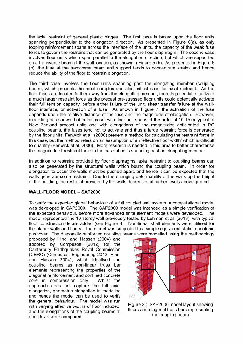
To verify the expected global behaviour of a full coupled wall system, a computational model was developed in SAP2000. The SAP2000 model was intended as a simple verification of the expected behaviour, before more advanced finite element models were developed. The model represented the 10 storey wall previously tested by Lehman et al. (2013), with typical floor construction details added (see Figure 8). Non-linear shell elements were utilised for the planar walls and floors. The model was subjected to a simple equivalent static monotonic pushover. The diagonally reinforced coupling beams were modelled using the methodology proposed by Hindi and Hassan (2004) and adopted by Compusoft (2012) for the Canterbury Earthquakes Royal Commission (CERC) (Compusoft Engineering 2012; Hindi and Hassan 2004), which idealised the coupling beams as non-linear truss bar elements representing the properties of the diagonal reinforcement and confined concrete core in compression only. Whilst the approach does not capture the full axial elongation, geometric elongation is modelled and hence the model can be used to verify the general behaviour. The model was run with varying effective widths of floor included, and the elongations of the coupling beams at each level were compared.
Figure 8 : SAP2000 model layout showing floors and diagonal truss bars representing
the coupling beam
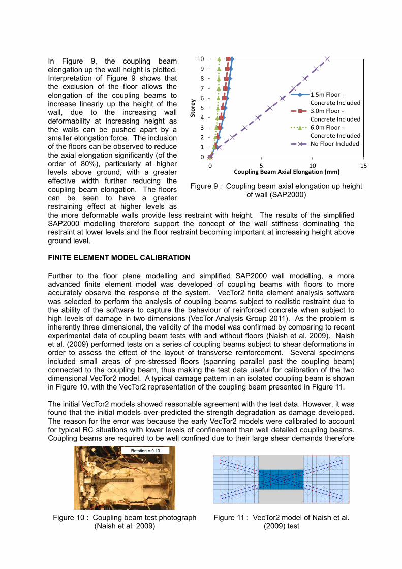
In Figure 9, the coupling beam elongation up the wall height is plotted. Interpretation of Figure 9 shows that the exclusion of the floor allows the elongation of the coupling beams to increase linearly up the height of the wall, due to the increasing wall deformability at increasing height as the walls can be pushed apart by a smaller elongation force. The inclusion of the floors can be observed to reduce the axial elongation significantly (of the order of 80%), particularly at higher levels above ground, with a greater effective width further reducing the coupling beam elongation. The floors can be seen to have a greater restraining effect at higher levels as the more deformable walls provide less restraint with height. The results of the simplified SAP2000 modelling therefore support the concept of the wall stiffness dominating the restraint at lower levels and the floor restraint becoming important at increasing height above ground level. FINITE ELEMENT MODEL CALIBRATION
Further to the floor plane modelling and simplified SAP2000 wall modelling, a more advanced finite element model was developed of coupling beams with floors to more accurately observe the response of the system. VecTor2 finite element analysis software was selected to perform the analysis of coupling beams subject to realistic restraint due to the ability of the software to capture the behaviour of reinforced concrete when subject to high levels of damage in two dimensions (VecTor Analysis Group 2011). As the problem is inherently three dimensional, the validity of the model was confirmed by comparing to recent experimental data of coupling beam tests with and without floors (Naish et al. 2009). Naish et al. (2009) performed tests on a series of coupling beams subject to shear deformations in order to assess the effect of the layout of transverse reinforcement. Several specimens included small areas of pre-stressed floors (spanning parallel past the coupling beam) connected to the coupling beam, thus making the test data useful for calibration of the two dimensional VecTor2 model. A typical damage pattern in an isolated coupling beam is shown in Figure 10, with the VecTor2 representation of the coupling beam presented in Figure 11. The initial VecTor2 models showed reasonable agreement with the test data. However, it was found that the initial models over-predicted the strength degradation as damage developed. The reason for the error was because the early VecTor2 models were calibrated to account for typical RC situations with lower levels of confinement than well detailed coupling beams. Coupling beams are required to be well confined due to their large shear demands therefore
Figure 9 : Coupling beam axial elongation up height of wall (SAP2000)
Figure 10 : Coupling beam test photograph (Naish et al. 2009)
Figure 11 : VecTor2 model of Naish et al. (2009) test
0
1
2
3
4
5
6
7
8
9
10
0 5 10 15
Sto
rey
Coupling Beam Axial Elongation (mm)
1.5m Floor -Concrete Included3.0m Floor -Concrete Included6.0m Floor -Concrete IncludedNo Floor Included
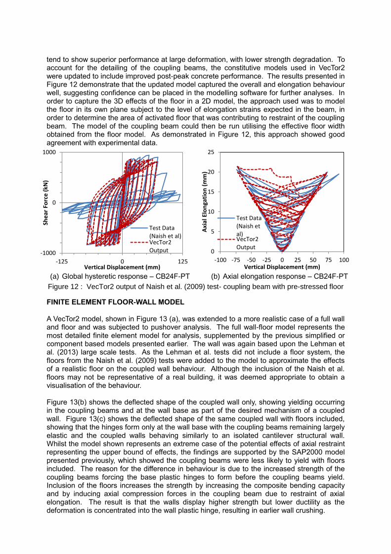
tend to show superior performance at large deformation, with lower strength degradation. To account for the detailing of the coupling beams, the constitutive models used in VecTor2 were updated to include improved post-peak concrete performance. The results presented in Figure 12 demonstrate that the updated model captured the overall and elongation behaviour well, suggesting confidence can be placed in the modelling software for further analyses. In order to capture the 3D effects of the floor in a 2D model, the approach used was to model the floor in its own plane subject to the level of elongation strains expected in the beam, in order to determine the area of activated floor that was contributing to restraint of the coupling beam. The model of the coupling beam could then be run utilising the effective floor width obtained from the floor model. As demonstrated in Figure 12, this approach showed good agreement with experimental data.
FINITE ELEMENT FLOOR-WALL MODEL A VecTor2 model, shown in Figure 13 (a), was extended to a more realistic case of a full wall and floor and was subjected to pushover analysis. The full wall-floor model represents the most detailed finite element model for analysis, supplemented by the previous simplified or component based models presented earlier. The wall was again based upon the Lehman et al. (2013) large scale tests. As the Lehman et al. tests did not include a floor system, the floors from the Naish et al. (2009) tests were added to the model to approximate the effects of a realistic floor on the coupled wall behaviour. Although the inclusion of the Naish et al. floors may not be representative of a real building, it was deemed appropriate to obtain a visualisation of the behaviour. Figure 13(b) shows the deflected shape of the coupled wall only, showing yielding occurring in the coupling beams and at the wall base as part of the desired mechanism of a coupled wall. Figure 13(c) shows the deflected shape of the same coupled wall with floors included, showing that the hinges form only at the wall base with the coupling beams remaining largely elastic and the coupled walls behaving similarly to an isolated cantilever structural wall. Whilst the model shown represents an extreme case of the potential effects of axial restraint representing the upper bound of effects, the findings are supported by the SAP2000 model presented previously, which showed the coupling beams were less likely to yield with floors included. The reason for the difference in behaviour is due to the increased strength of the coupling beams forcing the base plastic hinges to form before the coupling beams yield. Inclusion of the floors increases the strength by increasing the composite bending capacity and by inducing axial compression forces in the coupling beam due to restraint of axial elongation. The result is that the walls display higher strength but lower ductility as the deformation is concentrated into the wall plastic hinge, resulting in earlier wall crushing.
(a) Global hysteretic response – CB24F-PT (b) Axial elongation response – CB24F-PT
Figure 12 : VecTor2 output of Naish et al. (2009) test- coupling beam with pre-stressed floor
-1000
0
1000
-125 0 125
She
ar F
orc
e (
kN)
Vertical Displacement (mm)
Test Data(Naish et al)VecTor2Output 0
5
10
15
20
25
-100 -75 -50 -25 0 25 50 75 100
Axi
al E
lon
gati
on
(m
m)
Vertical Displacement (mm)
Test Data(Naish etal)VecTor2Output

CONCLUSIONS Previous research and observations made during the 2010/2011 Canterbury earthquakes have shown that the axial elongation of RC plastic hinges can significantly affect the behaviour of an RC structure due to the restraint forces generated by interacting structural components. The restraint is particularly significant in RC coupling beams due to the combined restraint contributions of the bounding structural walls and adjacent flooring systems. Modelling has been used to show that the elongation of coupling beams in a coupled wall-floor system can potentially alter the response of the coupled wall to seismic excitation by altering the strength hierarchy and reducing structural ductility. The restraint provided by the floors has been shown to be very complex and more research is needed in this area. VecTor2 finite element software has been shown to provide good agreement with experimental data of highly damaged coupling beams. Models such as that shown in Figure 13 (a) will be used as part of future research to better characterise the global behaviour.
REFERENCES
Canterbury Earthquakes Royal Commission. (2012). "Final Report Volumes 1-7." Rep. No. ISBN: 978-0-478-39558-7, New Zealand Government, Christchurch.
Compusoft Engineering. (2012). "CTV Building - Nonlinear Seismic Analysis Report. For Structure Smith Ltd and The Department of Building and Housing." Rep. No. 11033-00, Prepared by D. Bradley, T. Stuart, Christchurch.
Fenwick, R. C., Bull, D. K., MacPherson, C. J., and Lindsay, R. A. (2006). "The Influence of Diaphragms on Strength of Beams." NZSEE Conference, Napier(Paper Number 21), pp12.
Fenwick, R. C., and Megget, L. M. (1993). "Elongation and load deflection characteristics of reinforced concrete members containing plastic hinges." Bulletin of the New Zealand National Society for Earthquake Engineering, 26(1), 28-41.
Fenwick, R. C., and Thom, C. W. (1982). "Shear deformation in reinforced concrete beams subjected to inelastic cyclic loading / R.C. Fenwick and C.W. Thom." Rep. No. 279, University of Auckland School of Engineering, Auckland.
Fenwick, R. C., Bull, D. K., and Gardiner, D. (2010). "Assessment of Hollow Core Floors for Seismic Perfomance - University of Canterbury Research Report 2010-02." Rep. No. 2010-02, Christchurch.
(a) VecTor2 floor-wall model (b) Deflected shape
(no floor included) (c) Deflected shape (pre-
stressed floor included) Figure 13 : (VecTor2) Lehman et al. (2013) wall representation

Fenwick, R. C., Davidson, B. J., and Lau, D. B. N. (2005). "Interaction between ductile RC perimeter frames and floor slabs containing precast units." New Zealand Society for Earthquake Engineering Conference, Wairakei, New Zealand, Paper No 23.
Fenwick, R. C., Tankut, A. T., and Thom, C. W. (1981). "The deformation of reinforced concrete beams subjected to inelastic cyclic loading : experimental results." Rep. No. 268, University of Auckland School of Engineering, Auckland.
Fortney, P. J., Rassati, G. A., and Shahrooz, B. M. (2008). "Investigation on effect of transverse reinforcement on performance of diagonally reinforced coupling beams." ACI Struct.J., 105 (6)(S72), pp781.
Galano, L., and Vignoli, A. (2000). "Seismic behavior of short coupling beams with different reinforcement layouts." ACI Struct.J., 97(S89), pp876.
Hindi, R. A., and Hassan, M. A. (2004). "Shear capacity of diagonally reinforced coupling beams." Eng.Struct., 26(10), 1437-1446.
Kam, W. Y., Pampanin, S., and Elwood, K. (2011). "Seismic Performance of Reinforced Concrete Buildings in the 22 February Christchurch (Lyttelton) Earthquake." Bulletin of the New Zealand Society for Earthquake Engineering, 44(4), 239-278.
Kwan, A., and Zhao, Z. (2002). "Cyclic behaviour of deep reinforced concrete coupling beams." Proceedings of the ICE-Structures and Buildings, 152(3), 283-293.
Lehman, D., Turgeon, J., Birely, A., Hart, C., Marley, K., Kuchma, D., and Lowes, L. (2013). "Seismic Behavior of a Modern Concrete Coupled Wall." J.Struct.Eng., 139(8), 1371-1381.
MacPherson, C. J., Mander, J. B., and Bull, D. K. (2005). "Reinforced Concrete Seating Details of Hollow-Core Floor Systems." NZSEE Conference, 1(Taupo, New Zealand), Paper Number 24.
Matthews, J. G. (2005). "Hollow-Core Floor Slab Performance Following a Severe Earthquake." Rep. No. Commercial Report C2005-1, Prepared for EQC - 99/411, University of Canterbury, Christchurch, New Zealand.
Naish, D., Fry, J. A., Klemencic, R., and Wallace, J. (2009). "Experimental Evaluation and Analytical Modeling of ACI 318-05/08 Reinforced Concrete Coupling Beams Subjected to Reversed Cyclic Loading." Report SGEL, 6.
Paulay, T., and Binney, J. (1974). "Diagonally reinforced coupling beams of shear walls." ACI Special Publication, 42.
Peng, B. H. H., Dhakal, R. P., Fenwick, R. C., Carr, A. J., and Bull, D. K. (2011). "Elongation of Plastic Hinges in Ductile RC Members: Model Verification." Journal of Advanced Concrete Technology, 9(3), 327-338.
Tassios, T. P., Moretti, M., and Bezas, A. (1996). "On the behavior and ductility of reinforced concrete coupling beams of shear walls." ACI Struct.J., 93(6), 711-720.
VecTor Analysis Group. (2011). "VecTor2 - Finite Element Analysis of Reinforced Concrete." 3.5.