the effects of damage and uncertainty on the aeroelastic ... · aeroelastic / aeroservoelastic...
TRANSCRIPT

JAMS Meeting, June 2008
The Effects of Damage and The Effects of Damage and Uncertainty on the Uncertainty on the AeroelasticAeroelastic / / AeroservoelasticAeroservoelastic Behavior and Behavior and Safety of Composite Aircraft Safety of Composite Aircraft
Presented by Dr. Eli LivnePresented by Dr. Eli LivneDepartment of Aeronautics and AstronauticsDepartment of Aeronautics and Astronautics
University of WashingtonUniversity of Washington

2
Contributors
• Department of Aeronautics and Astronautics• Dr. Luciano Demasi, post-doctoral research fellow• Dr. Andrey Styuart, research scientist, assistant professor temp.• Dr. Eli Livne – PI, Professor
• Department of Mechanical Engineering• Francesca Paltera, graduate student• Dr. Mark Tuttle, co-PI, professor and chairman
• Boeing Commercial, Seattle• Dr. James Gordon, Associate Technical Fellow, Flutter Methods
Development• Carl Niedermeyer, Manager, 787/747 Flutter Engineering & Methods
Development • Dr. Kumar Bhatia, Senior Technical Fellow, Aeroelasticity and
Multidisciplinary Optimization • FAA Technical Monitor
• Curtis Davies, Program Manager of JAMS, FAA/Materials & Structures• Other FAA Personnel Involved
• Dr. Larry Ilcewicz, Chief Scientific and Technical Advisor for Advanced Composite Materials

3
Scope
• Motivation & Key Issues
• Probabilistic approach to the aeroelastic reliability of damaged composite aircraft
• Automated simulation capabilities for uncertainty analysis: – Linear structural dynamics – Nonlinear structural dynamics
• Experimental aeroelastic capabilities– Development– Status

4
Motivation and Key Issues
• Variation (over time) of local structural characteristics might lead to a major impact on the global aeroservoelastic integrity of flight vehicles.
• Sources of uncertainty in composite structures: – Material property statistical spread– Damage– Delamination– Joint/attachment changes– Debonding– Environmental effects, etc.
• Nonlinear structural behavior: – Delamination, changes in joints/attachments stiffness and damping, as well as
actuator nonlinearities may lead to nonlinear aeroelastic behavior such as Limit Cycle Oscillations (LCO) of control surfaces with stability, vibrations, and fatigue consequences.
• Nonlinear structural behavior:– Highly flexible, optimized composite structures (undamaged or damaged) may exhibit
geometrically nonlinear structural behavior, with aeroelastic consequences.
• Modification of control laws later in an airplane’s service can affect dynamic loads and fatigue life.
5
Objectives
• Develop computational tools (validated by experiments) for automated local/global linear/nonlinear analysis of integrated structures/ aerodynamics / control systems subject to multiple local variations/ damage.
• Develop aeroservoelastic probabilistic / reliability analysis for composite actively-controlled aircraft.
• Link with design optimization tools to affect design and repair considerations.
• Develop a better understanding of effects of local structural and material variations in composites on overall Aeroservoelastic integrity.
• Establish a collaborative expertise base for future response to FAA, NTSB, and industry needs, R&D, training,and education.

6
Approach
– Work with realistic structural / aeroelastic models using industry-standard tools.
– Integrate aeroelasticity work with work on damage mechanisms and material behavior in composite airframes.
– Develop aeroelastic simulation capabilities for structurally nonlinear systems, with nonlinearity due to damage development and large local or global deformation
– Use sensitivity analysis and approximation techniques from structural / aeroelastic optimization (the capability to run many simulations efficiently) as well as reliability analysis to create the desired analysis / simulation capabilities for the linear and nonlinear cases.
– Build a structural dynamic / aeroelastic testing capability and carry out experiments.

7
Approach
• Efficient simulation of linear aeroservoelastic behavior to allow rapid reliability assessment:
– Dedicated in-house tools development (fundamentals, unique features, innovations)
– Integrated utilization of industry-standard commercial tools (full scale commercial aircraft)
• Efficient simulation of nonlinear aeroservoelastic behavior, including limit cycle oscillations (LCO):
– Tools development for basic research and physics exploration: simple, low order systems
– Tools development for complex, large-scale aeroelastic systems with multiple nonlinearities
• Reliability assessment capability development for linear and nonlinear aeroservoelastic systems subject to uncertainty.
• Aeroservoelastic reliability studies with resulting guidance for design and for maintenance.
• Structural dynamic and future aeroelastic tests of aeroelastically scaled models to support aspects of the simulation effort described above.

8
Aeroelastic Reliability of Undamaged / Damaged
Composite Aircraft

9
Aeroelastic Reliability
The UW’s Reliability Lifecycle Analysis of Composite Structures, RELACS (developed for damage tolerance studies of composite airframes by Lin & Styuart at the University of Washington) is extended here and adapted to the aeroelastic reliability problem, where (in addition to residual strength) residual stiffness and residual flutter speeds are tracked over time of service, and the probability of flutter events due to uncertainty in flutter characteristics AND operational speeds / dynamic pressures is assessed.
-0.1
9.9
19.9
29.9
39.9
49.9
0 0.5 1Time
Dam
age
Size
DisbondH l
Flutter Speed degradation due to
aging
0 . 5
0 . 7
0 . 9
1. 1
0 0 . 2 0 . 4 0 . 6 0 . 8 1
T ime
Res
.Flu
tter
Spe
ed
Disbond Hole
0
0.2
0.4
0.6
0.8
1
1.2
0 0.5 1
Res
.Flu
tter
Spe
ed
Time
Combined Damage+Aging
DisbondHole
Damage initiation
Damage propagation
Damage repair/part replacement

10
Sources of Uncertainty
• Material & structural component properties: – Manufacturing– Degradation over service life
• Damage– Type– Size– Location– Delectability
• Maintenance procedures– Inspection– Repair
• Operation– Statistics of loading & flight conditions
11
VATM - Virtual Aeroelastic Test Module
1. Construction of the structural finite element analysis (FEA) structural model: MD/MSC NASTRAN/PATRAN (each elastic finite element of the model should have its own property card and material card).
2. Aeroelastic model construction: Unsteady Aerodynamics & Flutter Solution: NASTRAN.
3. To model the randomly varied test structures, the property and materials cards of the NASTRAN input file are changed by the appropriate Microsoft VBA-based module.
4. VATM runs the NASTRAN solver using randomized input files.
5. NASTRAN output file is analyzed by VATM module to obtain flutter velocity and frequency. The output data along with some input data are accumulated and stored in a database.
6. After a certain number of steps 3-5 runs, VATM conducts the statistical analysis of the data obtained.

12
Automated System for Calculating Flutter Speeds of Large Numbers of Airframe Structural Variations
For flutter –NASTRAN onlyMay be used

13
VATM - Virtual Aeroelastic Test Module:
Generation of Randomly Distributed Structures
• The correlation of properties and material parameters reflects expected characteristics of structural subcomponents that are manufactured separately and then assembled.
• The properties of individual finite elements belonging to skin panels, spars, stringers, and frames are considered correlated within each panel, spar, etc., respectively.
• Spatially distributed uncertainties considered in a form of Markov field. The covariance kernel of the random field is often assumed in the form:
(where σp2 is a field variance and Rcor is a radius of
correlation).• Properties of structural subcomponents manufactured
separately are assumed independent.
1| |2
1( , ) cor
x xR
pC x x eσ− −
=

14
VATM - Virtual Aeroelastic Test Module: Operating Environments Statistics (for Flutter)
• The cumulative density function (CDF) FVa for maximum flown airspeed per life:
where F(V/ VD) is the probability of speed exceedance per one flight, and Nf is a number of flights per life.
• Conservative parameters of FVa were obtained and this CDF is cast in a form:
where z = V/VD .
( / ) exp{ exp[ ( / )] }Va D D fF V V F V V N= − ⋅
1( / ) ( ) exp exp0.0063Va D Va
zF V V F z ⎡ − ⎤⎛ ⎞= = − −⎜ ⎟⎢ ⎥⎝ ⎠⎣ ⎦

15
Representative Vetical Tail / Rudder System
Structures:• Number of grid points =1268• Number of CBAR elements = 309• Number of CBUSH elements = 45• Number of CONM2 elements = 28• Number of CQUAD4 elements = 1409• Number of CROD elements = 1056• Number of CSHEAR elements = 91• Number of CTRIA3 elements =187• Number of RBE2 elements =16• Number of RBE3 elements = 28
Unsteady Aerodynamics – Doublet Lattice

16
Key Mode Shapes for the Composite Tail / Rudder Flutter Mechanisms
16.34 Hz 18.24 Hz
Nominal Structure

17
Statistical Flutter Results for the Tail / Rudder System
• Structural Variability
• Flutter results
• Note: The flutter PDF is multi-modal. Some members of the fleet may have flutter due to mechanisms different from those of others.
• The variance of VF is noticeably greater than variances for input parameters (in this case)
Property Panel-to-panel C.O.V.
Element-to-element C.O.V.
Radius of Correlation, in
Thickness t 0.03 0.01 10
G11 0.05 0.02 100
G22 0.05 0.02 100
G12 0.05 0.02 100

18
Effect of Damage Statistics on Flutter
• Condition: a randomly selected element of the tail torsion box skin has damage of given size.
• Damage assumed at the center of element.• Locations of damaged elements - chosen randomly with uniform distribution
over the tail box skin area.• Residual stiffness (K) of damaged element:
– D: damaged; U: undamaged– W: width– T: tension; C: compression
• Results:
( ) ( )
( ) ( )
;D DT T U T D
D DC C U C D
W W WW W
W W WW W
κ κ κ
κ κ κ
−⎛ ⎞ ⎛ ⎞= +⎜ ⎟ ⎜ ⎟⎝ ⎠ ⎝ ⎠
−⎛ ⎞ ⎛ ⎞= +⎜ ⎟ ⎜ ⎟⎝ ⎠ ⎝ ⎠
Empirical CDF of VF for damaged and undamaged structure

19
VATM – RELACS Studies
• Statistical flutter results from the VATM simulations were now combined with flutter runs for damaged structures using RELACS.
• Number of Design Cases = 1; Subsonic flight. • Number of Damage Types = 2; Hole and Delamination.• Number of Inspection Types =2; Visual and Instrumental. • The CDF of maximum airspeed per life – shown previously. • The probability of damage detection model described previously by Styuart,
Mor, Lin & Livne.• The exceedance data of damage occurrence is taken from Report DOT/FAA/AR-
01/55, 2002 and recalculated for 60000 flight hours and torsion box skin area.
Damage exceedencecurve
Probability of failure vs. designsafety margin

20
VATM – RELACS A Unique Capability for Monte-Carlo Based Assessment of Aeroelastic
Reliability in Damaged and Undamaged Composite Airframes
Combine:• Statistical generator of FE models for composite airframes
subject to manufacturing variation, material degradation, and damage effects.
• Statistics of flight operations (flight speeds exceedances)• Statistics of inspections and repair.• Automated rapid aeroelastic model generation, flutter
simulations, results extraction and storage.• Monte Carlo simulations.To obtain:• Flutter statistics and flutter reliability assessment for composite
airplanes.• Statistical sensitivities to all input parameters.To yield:• Understanding of the complex composite airplanes flutter
variability problem and its key mechanisms and influences.• Design and maintenance procedures.• Guidance for research and development.

21
Details - in the following publications
• Styuart, A., Mor, M., Livne, E., and Lin, K., “Risk Assessment of Aeroelastic Failure Phenomena in Damage Tolerant Composite Structures”, in final stages of the review process in final preparation for publication, AIAA Journal.
• Styuart, A., Mor, M., Livne, E., and Lin, K., “Risk Assessment of Aeroelastic Failure Phenomena in Damage Tolerant Composite Structures”, AIAA Paper 2007-1981, 48th AIAA/ASME/ASCE/AHS/ASC Structures, Structural Dynamics, and Materials Conference, Honolulu, Hawaii, Apr. 23-26, 2007
• Styuart, A., Demasi, L., Livne, E., and Lin, K., “Probabilistic Modeling of Aeroelastic Life Cycle for Risk Evaluation of Composite Structures”, AIAA-2008-2300, 49th AIAA/ASME/ASCE/AHS/ASC Structures, Structural Dynamics, and Materials Conference, Schaumburg, IL, Apr. 7-10, 2008
• Styuart, A., Demasi, L., Livne, E., and Lin, K., “Probabilistic Modeling of Aeroelastic Life Cycle for Risk Evaluation of Composite Structures”, in preparation for submission: AIAA Journal.
22
Extensions
• Combine failure mechanisms due to damage tolerance (quasi-steady maneuver loads) with flutter and dynamic maneuver loads (gust) and integrate into VATM/RELACS capability.
• Carry out reliability studies covering both damage tolerance and flutter, steady and dynamic loading cases.
• Extend to the nonlinear problem of limit cycle oscillations (LCO) of realistic tail / rudder systems or any lifting surface / control surface due to freeplay and other nonlinearities (probabilistic studies of LCO behavior using simple tail / rudder configurations were completed and reported in earlier JAMS meetings)

23
Nonlinear Aeroelasticity of Optimized Composite Structures Without and With
Damage

24
Motivation & Importance
• With an automated rapid linear flutter capability in place (as described earlier), it is important to add to the VATM/RELACS capability an automated capability for nonlinear aeroelastic simulations.
• Nonlinear aeroelastic behavior can be caused by structural nonlinearities, aerodynamic nonlinearities, or both.
• Important nonlinear aeroelastic behavior can be captured using linear or linearized unsteady aerodynamics (that is, without the heavy cost of fully nonlinear CFD).
• With light weight optimized composite airframes at high subsonic speeds, geometric structural nonlinearities become important and lead to nonlinear aeroelastic behavior even when the unsteady aerodynamic behavior is still essentially linear.
• Damage can lead to structural sub-components (panels, etc.) operating near or above their buckling loads, and, thus, to nonlinear aeroelastic behavior
• Local nonlinear structural behavior (including the effect of damage) at actuator locations, hinges, and joints may vary throughout the service life and must be modeled in any aeroelastic reliability studies of composite wing / control surface configurations.

25
New aeroelastic simulation methods for geometrically nonlinear structural behavior coupled with linear unsteady aerodynamics
• Full order nonlinear Finite Element based structural dynamics (allowing for the simulation of large deformation, approach to buckling, and post-buckling behavior)
• Linear unsteady aerodynamics (Doublet Lattice, ZAERO, etc.) or CFD- based linearized unsteady aerodynamics – Full Order or modally reduced-order.
• Coupled nonlinear aeroelastic simulations in the time domain

26
Mathematical details – in publications
• Demasi, L., and Livne, E., “Dynamic Aeroelasticity of Structurally Nonlinear Configurations Using Linear Modally Reduced Aerodynamic Generalized Forces”, accepted for publication, AIAA Journal.
• Demasi, L., and Livne, E., “Aeroelastic Coupling of Geometrically Nonlinear Structures and Linear Unsteady Aerodynamics: Two Formulations”, AIAA- 2008-1758, 49th AIAA/ASME/ASCE/AHS/ASC Structures, Structural Dynamics, and Materials Conference, Schaumburg, IL, Apr. 7-10, 2008
• Demasi, L., and Livne, E., “Dynamic Aeroelasticity Coupling Full Order Geometrically Nonlinear Structures and Full Order Linear Unsteady Aerodynamics - The Joined Wing Case”, AIAA-2008-1818, 49th AIAA/ASME/ASCE/AHS/ASC Structures, Structural Dynamics, and Materials Conference, Schaumburg, IL, Apr. 7-10, 2008

27
Effect of loading on the natural frequencies of a geometrically nonlinear airframe
• Note: the Joined Wing configuration is a prototype configuration which exhibits structural nonlinear behavior of the type found in optimized built-up composite airframes such as local buckling, shifting of natural frequencies, etc. It is used here to validate the new simulation methods.

28
Results of nonlinear aeroelastic transient vs. steady state simulations
Vertical displacements at three differentPoints on the configuration: steady state vs. time domain results.Nonlinear structural behavior.Subcritical flight speed.

29
Limit Cycle Oscillations (LCO)
• LCO due to control surface freeplay – simulation capabilities developed and reported in earlier years
• LCO due to structural geometric nonlinearity – new simulation capabilities
Response at a subcritical speed Response at a speed above the consistent flutter speed

30
Extensions
• Implement in a NASTRAN based nonlinear aeroelastic process to be used by industry.
• Study nonlinear aeroelastic behavior of optimized realistic composite airframes, including the effects of damage
• Implement in a parallel processing environment and integrate into VATM / RELACS for aeroelastic reliability studies.
• Design, build, and test representative prototype configurations exhibiting nonlinear aeroelastic behavior and the effects of damage.

31
Aeroelastic Experimental Capability and
Flutter Experiments

32
Experiments and experimental capabilities development
Goals:
• Develop a low-cost rapid aeroelastic testing capability at the UW for studies of aeroelastic problems of interest, with special emphasis on
– Composites– damaged airframesand – nonlinear aeroelastic behavior
• Use tests to validate and calibrate numerical models
• Use tests to support FAA / NTSB work

33
Experiments and experimental capabilities development
Approach:
• Start with simple models for which experimental and theoretical results already exist – the Duke U wing / control surface LCO model
• Expand and generalize by adding – Composite construction components– Nonlinearity types for the actuator and support system– Simulation of damage in different mechanisms: debonding, attachment
failure, delamination, hinge failure
• Develop the model design & construction and test conduction as ell as data processing hardware and software tools
• Use as a foundation upon which to build aeroelastic experimental capabilities using more complex models
– first an empennage with multiple interacting nonlinearities for the 3 x 3 tunnel
– Later, large aeroelastic models and associated tests at the Kirsten wind tunnel

34
UW Flutter Test Wing / Control Surface Design mounted vertically in the UW A&A 3 x 3 wind tunnel
∞U
Wing - wind tunnel mountProviding linearPlunge And torsional pitch stiffnesses
Simulated actuator attachment allowing for different nonlinearities
Aluminum wing allowing for variable inertia / cg properties
Rudder – composite construction allowing for simulations of damage and hinge failure

35
RudderWing
Pivot Tube
Ballast TubeRibs
Hinge Shaft
Hinge Tube
35°

36
Hinge TubeCarbon Fiber Skin
Foam core damage
• Damage modes– Debonding.– Delamination– Core cracking– Hinge failure
Hinge Slots
Debonding
Debonding

37
The tail / rudder model at the UW’s 3 x 3 wind tunnel
38
Development of Experimental Capabilities - Status
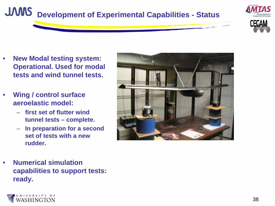
• New Modal testing system: Operational. Used for modal tests and wind tunnel tests.
• Wing / control surface aeroelastic model:
– first set of flutter wind tunnel tests – complete.
– In preparation for a second set of tests with a new rudder.
• Numerical simulation capabilities to support tests: ready.

39
Extensions
• Complete modal and flutter tests of tail / rudder system with new composite rudder.
• Test tail / rudder system (modal tests and wind tunnel flutter tests) with damaged hinge(s).
• Test tail / rudder system with rudder damage due to debonding.
• Correlate with computer simulations and validate computer simulation capabilities.
• Extend experiments and numerical simulations to the case of empennage carrying composite horizontal and vertical tails with elevators and rudders in the presence of multiple interacting nonlinearities.

40
Contribution to Undergraduate Education:
Structural and Aeroelastic Aspects of Composite Airplane Design

41
Contribution to undergraduate education
• Use the simulation capabilities and experimental capabilities developed in the present program to introduce aspects of airframe composite design, construction, FE analysis, and static and dynamic structural testing into the undergraduate curriculum.
• The 2008 capstone airplane design course at the University of Washington: Develop a small UAV for studies of engine shielding effects on the noise signature of transport aircraft configurations.

42
Prototype composite wing box
NASTRAN modelInternal structure
Static loading test
Kevlar/Epoxy
Graphite / Kevlar / Epoxy
Load / deflection Test / analysiscorrelation

43
Prototype wing mode shapes: Analysis / test correlation
(The new modal testing system was used for modal tests)
Mode 1: First BendingNASTRAN: 37.8 HzTested: 37.5 Hz
Mode 2: Second BendingNASTRAN: 155.8 HzTested: 156.2 Hz
Mode 3: Third BendingNASTRAN: 163.1 HzTested: 162.5 Hz
Mode 8: First TorsionNASTRAN: 335.4 HzTested: 343.5 Hz

44
Failure in static loading test: Buckling of rear root panel under compression. Correlation of nonlinear NASTRAN predictions
and static test
Nonlinear NASTRAN simulation: Rear root panel already buckled at 100 lbs tip load
Test: Rear root panel buckled between 70 and 100 lbs tip load. Internal
structural failure at root area at 100 lbs tip load.

45
Scope of airframe structural work in the 2008 senior capstone airplane design course
• Coupon tests for material properties using different layups.
• Design and construction of a prototype wing box (composite).
• FE analysis of the wing box: linear and nonlinear, static and dynamic.
• Static loading tests to failure. Test / analysis correlation.
• Modal tests. Test / analysis correlation.
• Design and construction of the complete airframe (composite).
• FE analysis (static, dynamic, and aeroelastic) of the whole UAV.
• Planned static and dynamic tests of the UAV.

46
Conclusion• Progress in all major areas of this R&D effort:
– Efficient simulation tools for uncertain airframes covering flutter and LCO constraints, including linear and nonlinear structural models.
– Automated systems for rapid simulations of large number of systems’ variations, needed for probabilistic / reliability analysis.
– A mix of in-house capabilities (allowing studies non-standard techniques and flexibility in tools development) and industry-standard commercial capabilities (for improved interaction with industry).
– Lifetime reliability studies of composite wing / control surface systems: simple wings and a realistic tail / rudder system.
– Formulation of a comprehensive approach to the inclusion of aeroelastic failures in the reliability assessment of composite aircraft, and resulting benefits to both maintenance and design practices.
– Experimental capability now operational with modal and flutter tests underway.
– A significant undergraduate educational component: design, build, simulate, and structurally test composite airframes.

47
Benefits to Aviation
– Formulation of a comprehensive approach to the inclusion of aeroelastic failures in the reliability assessment of composite aircraft, and resulting benefits to both maintenance and design practices, covering:
– Different damage types in composite airframes and their statistics;
– Aeroelastic stability due to linear and nonlinear mechanisms;
– Aeroelastic response levels (vibration levels and fatigue due to gust response and response to other dynamic excitations);
– Theoretical, computational, and experimental work with aeroelastic systems ranging from basic to complex full-size airplanes, to serve as benchmark for industry methods development and for understanding basic physics as well as design & maintenance tradeoffs.