the effects of higher strength and associated concrete properties
TRANSCRIPT
The Effects of Higher Strength andAssociated Concrete Properties on Pavement PerformancePUBLICATION NO. FHWA-RD-00-161 JUNE 2001
Research, Development, and TechnologyTurner-Fairbank Highway Research Center6300 Georgetown PikeMcLean, VA 22101-2296
FOREWORD
This report documents the investigation of the effect of strength and other associated concrete properties of the long-term performance of concrete pavements. Performance criteria used included joint spalling, faulting and transverse slab cracking. Project variables included pavement age, traffic, climate, distress levels and types, joint spacing and compressive strength. Compressive strength was found to correlate well with permeability. Concrete characteristics found to be desirable include compressive strength in the 45 to 50 MPa range, flexural strength in the 4.5 to 6.0 range, non-alakali reactive aggregate that is freeze-thaw distress resistant, a well-graded aggregate with large top size, water-cement ratio of 0.42 to 0.45 and cement content of approximately 335 kg/m3. Prototype mixture designs were developed for different climatic regions. This report will be of interest to those involved in concrete pavement mixture design, as well as those involved in the design, construction and analysis of concrete pavements. Sufficient copies are being distributed to provide 10 copies to each FHWA Resource Center, five copies to each FHWA Division, and five copies to each State highway agency. Direct distribution is being made to the FHWA Division Offices. Additional copies may be purchased from the National Technical Information Service (NTIS), 5285 Port Royal Road, Springfield, Virginia 22161.
T. Paul Teng, P. E. Director, Office of Infrastructure, Research and Development
NOTICE
This document is disseminated under the sponsorship of the Department of Transportation in the interest of information exchange. The United States Government assumes no liability for its contents thereof. This report does not constitute a standard, specification, or regulation. The United States Government does not endorse products or manufacturers. Trademarks or manufacturer’s names appear herein only because they are considered essential to the object of this document.
Technical Report Documentation Page 1. Report No. FHWA-RD-00-161
2. Government Accession No.
3. Recipient's Catalog No.
5. Report Date June 2001
4. Title and Subtitle The Effects of Higher Strength and Associated Concrete Properties on Pavement Performance
6. Performing Organization Code
7. Author(s) W. Hansen, E.A. Jensen, and P. Mohr
8. Performing Organization Report No.
10. Work Unit No. (TRAIS)
9. Performing Organization Name and Address University of Michigan, 2340 G.G. Brown, Ann Arbor, MI 48109-2125
11. Contract or Grant No. DTFH61-95-C-00108
13. Type of Report and Period Covered Final Report 1995-2001
12. Sponsoring Agency Name and Address Federal Highway Administration, Research, Development and Technology; 6300 Georgetown Pike McLean, Virginia 22101-2296 14. Sponsoring Agency Code
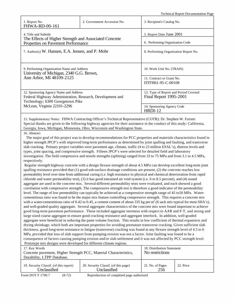
HRDI-12 15. Supplementary Notes: FHWA Contracting Officer’s Technical Representative (COTR): Dr. Stephen W. Forster Special thanks are given to the following highway agencies for their assistance in the conduct of this study: California, Georgia, Iowa, Michigan, Minnesota, Ohio, Wisconsin and Washington State. 16. Abstract The major goal of this project was to develop recommendations for PCC properties and materials characteristics found in higher strength JPCP’s with improved long-term performance as determined by joint spalling and faulting, and transverse slab cracking. Primary project variables were pavement age, climate, traffic (4 to 23 million ESAL’s), distress levels and types, joint spacing, and compressive strength. Fifteen JPCP’s were selected for detailed field and laboratory investigation. The field compressive and tensile strengths (splitting) ranged from 33 to 75 MPa and from 3.1 to 4.5 MPa, respectively. Regular strength highway concrete with a design flexure strength of about 4.5 MPa can develop excellent long-term joint spalling resistance provided that (1) good sub-surface drainage conditions are present, (2) the concrete reaches low permeability level over time from additional curing (i.e. high resistance to physical and chemical deterioration from rapid chloride and water permeability test), (3) it has good entrained air void system (i.e. 6 to 8.5 percent), and (4) sound aggregate are used in the concrete mix. Several different permeability tests were evaluated, and each showed a good correlation with compressive strength. The compressive strength test is therefore a good indicator of the permeability level. The range of low permeability can typically be achieved at a compressive strength range of 45 to50 MPa. Water-cementitious ratio was found to be the major mix feature controlling compressive strength. This requires a concrete mix with a water-cementitious ratio of 0.42 to 0.45, a cement content of about 335 kg per m3 (6 sack mix typical for most SHA’s), and well-graded quality aggregate. Several aggregate characteristics of the concrete mix were found important to achieve good long-term pavement performance. These included aggregate inertness with respect to AAR and F-T, and strong and large sized coarse aggregate to ensure good cracking resistance and aggregate interlock. In addition, well-graded aggregate were beneficial in reducing the paste volume fraction. This results in low coefficient of thermal expansion and drying shrinkage, which both are important properties for avoiding premature transverse cracking. Given sufficient slab thickness, good long-term resistance to fatigue (transverse) cracking was found at any flexure strength level of 4.5 to 6 MPa, provided that loss of slab support from pumping erosion was not a factor. Joint faulting was found to be a consequence of factors causing pumping erosion and/or slab settlement and it was not affected by PCC strength level. Prototype mix designs were developed for different climate regions. 17. Key Words Concrete pavement, Higher Strength PCC, Material Characteristics, Durability, LTPP Database.
18. Distribution Statement No restrictions
19. Security Classif. (of this report)
Unclassified
20. Security Classif. (of this page)
Unclassified
21. No. of Pages
256
22. Price
Form DOT F 1700.7 (8-72) Reproduction of completed page authorized
ii
iii
TABLE OF CONTENTS
VOLUME I: FINAL REPORT Section Page INTRODUCTION ..................................................................................................... 1 Background .......................................................................................................... 1 Project Objectives ................................................................................................ 2 Project Phases ...................................................................................................... 2 Advisory Panel..................................................................................................... 3 Overview of the Report ....................................................................................... 3 1. LITERATURE REVIEW SUMMARY ON “EFFECTS OF
INCREASING STRENGTH AND ASSOCIATED PCC PROPERTIES ON LONG-TERM PAVEMENT PERFORMANCE”........................................ 5 1.1 Introduction.................................................................................................. 5 1.2 PCC Properties and Material Characteristics for European Higher
Strength JPCP............................................................................................... 5 1.2.1 Required Levels of PCC Properties and Material
Characteristics.................................................................................... 6 1.2.2 European Concrete Pavement Demonstration Project in
Michigan............................................................................................ 6 1.3 Trends in Pavement PCC from the LTPP Database .................................. 11
1.3.1 Regional PCC Trends in the LTPP Database .................................. 11 1.3.2 Preliminary Performance Trends in the LTPP Database ................. 12
1.4 Concrete Properties with Significant Influence on Jointed Concrete Pavement Performance............................................................................... 12 1.4.1 Crack and Joint Faulting .................................................................. 15 1.4.2 Crack and Joint Spalling .................................................................. 17 1.4.3 Transverse Cracking and Corner Breaks ......................................... 19
1.5 PCC Properties and Materials Characteristics with Significant Influence on Pavement Performance.......................................................... 27 1.5.1 Flexural and Splitting Tensile Strength........................................... 28 1.5.2 Compressive Strength...................................................................... 29 1.5.3 Elastic Modulus ............................................................................... 30 1.5.4 Fracture Energy ............................................................................... 30 1.5.5 Permeability..................................................................................... 31 1.5.6 Air Content and Freeze-Thaw Durability........................................ 32 1.5.7 Coefficient of Thermal Expansion................................................... 32 1.5.8 Coarse Aggregate Characteristics Affecting Joint/Crack LTE........ 33
2. RESEARCH METHODOLOGY FOR DETAILED FIELD AND
LABORATORY EVALUATION..................................................................... 35 2.1 Information on Pavement Performance, PCC Properties, and Material
Characteristics Obtained from the SHRP LTPP Database......................... 36

iv
TABLE OF CONTENTS (CONTINUED) Section Page
2.1.1 Overview of the LTPP Database ..................................................... 36
2.1.2 Available Information in the LTPP Database .................................. 36 2.2 Selection of Candidate Pavement Sections ................................................ 38
2.2.1 Introduction...................................................................................... 38 2.2.2 Climate............................................................................................. 38 2.2.3 Concrete Strength ............................................................................ 39 2.2.4 Distress ............................................................................................ 39 2.2.5 Pavement Age .................................................................................. 40 2.2.6 Traffic .............................................................................................. 40 2.2.7 Joint Spacing and Reinforcement .................................................... 40 2.2.8 Other Design Parameters ................................................................. 41
2.3 Details of Field Evaluation of Selected Pavement Sections ...................... 41 2.3.1 Introduction...................................................................................... 41 2.3.2 Background Information.................................................................. 41 2.3.3 General Site Visit............................................................................. 42 2.3.4 Visual Survey................................................................................... 42 2.3.5 Coring .............................................................................................. 47 2.3.6 Falling Weight Deflectometer ......................................................... 47 2.3.7 Dipstick Profilometer Data .............................................................. 48
2.4 Details of Laboratory Evaluation of Selected Pavement Sections ............. 48 2.4.1 Methods to Determine Compressive Strength, Splitting Tensile
Strength, and Elastic Modulus ......................................................... 49 2.4.2 Method to Determine Fracture Energy ............................................ 49 2.4.3 Transport Property Test Methods .................................................... 51 2.4.4 Coefficient of Thermal Expansion................................................... 57 2.4.5 Petrographic Analysis of Cored Samples ........................................ 61
3. RESULTS OF FIELD AND LABORATORY INVESTIGATIONS ............... 63
3.1 Field Test Sites........................................................................................... 63 3.1.1 Test Sections in the DNF and DF Regions ...................................... 69 3.1.2 Test Sections in the Wet Freeze Region.......................................... 76 3.1.3 Test Sections in the Wet No Freeze Region.................................... 81
3.2 PCC Sample Description and Petrographic Analysis ................................ 84 3.2.1 Petrographic Characterization of PCC Specimens from the
Dry-No-Freeze and Dry-Freeze Regions ......................................... 85 3.2.2 Petrographic Characterization of PCC Sections from the Wet-
Freeze Region.................................................................................. 92 3.2.3 Petrographic Characterization of PCC Sections from the Wet-
No Freeze Region ............................................................................ 98 3.2.4 Summary of Petrographic Analysis ............................................... 101
3.3 Presentation of Field and Laboratory Results on Concrete Properties..... 103

v
TABLE OF CONTENTS (CONTINUED) Section Page
3.3.1 Compressive Strength, Splitting Tensile Strength, and Elastic Modulus ......................................................................................... 103
3.3.2 Fracture Energy ............................................................................. 105 3.3.3 Transport Properties....................................................................... 106 3.3.4 Coefficient of Thermal Expansion................................................. 112
4. PAVEMENT PERFORMANCE..................................................................... 113
4.1 Introduction................................................................................................ 113 4.1.1 Pavement Distress at the Time of Field Testing ............................ 113
4.2 Joint and Crack Faulting ............................................................................ 117 4.2.1 Joint Faulting from Slab Settlement or Pumping Erosion............. 117 4.2.2 Individual Joint/Crack Faults versus Section Average .................. 122 4.2.3 Development of Faulting ............................................................... 125 4.2.4 Aggregate Interlock and Pavement Performance .......................... 127
4.3 Transverse Cracking .................................................................................. 130 4.3.1 Effect of Higher Cement Content on Transverse Cracking........... 130 4.3.2 Transverse Cracking of JPCP on CTB due to Pumping Erosion... 130 4.3.3 Location of Transverse Cracking................................................... 131 4.3.4 Extent of Loss of Joint Support in JPCP on CTB from FWD
Testing ........................................................................................... 133 4.3.5 When Pumping Erosion Does Not Develop .................................. 136
4.4 Factors Affecting Joint Spalling ................................................................ 140 5. CONCRETE PROPERTIES ........................................................................... 143
5.1 Investigated Strength Range ...................................................................... 143 5.1.1 Field and LTPP Comparison of PCC Mechanical Properties........ 144 5.1.2 Estimated Flexural Strength versus Compressive Strength for
This Study...................................................................................... 145 5.1.3 Ultimate versus 28-day Design Compressive Strength................. 147
5.2 Compressive Strength................................................................................ 148 5.3 Effect of Increasing Compressive Strength on the Splitting Tensile Strength...................................................................................................... 149
5.3.1 Prediction of Splitting Tensile Strength From Compressive Strength.......................................................................................... 151
5.4 Effect of Increasing Strength on Elastic Modulus ..................................... 151 5.4.1 Prediction of Elastic Modulus from Compressive Strength.......... 153 5.4.2 Increasing Elastic Modulus and Splitting Tensile Strength........... 153
5.5 PCC Fracture Resistance ........................................................................... 154 5.5.1 Resistance to Crack Initiation........................................................ 154 5.5.2 PCC Brittleness Models................................................................. 156 5.5.3 Fracture Energy from Field Concretes .......................................... 156 5.5.4 PCC Brittleness and Fracture Energy ............................................ 157
vi
TABLE OF CONTENTS (CONTINUED) Section Page
5.6 Effect of Higher Strength on Concrete Transport Properties .................... 161 5.6.1 Effect of Higher Strength on PCC Transport Properties ............... 162 5.6.2 Effect of Climate and Drainage ..................................................... 169 5.6.3 Variation of Permeability with Depth Below the Slab Surface ..... 171
5.7 Air Void System and Freeze-Thaw Resistance ......................................... 174 5.7.1 Air Void System of Higher Strength Concrete in the WF
Region ........................................................................................... 174 5.7.2 When the Air Void Structure is Rendered Ineffective ................... 176
5.8 Concrete Shrinkage and Coefficient of Thermal Expansion..................... 179 5.8.1 Drying Shrinkage ........................................................................... 179 5.8.2 CTE Test Results and Ranges for the Pavements Investigated ..... 180
6. CONCRETE MIX CHARACTERISTICS ...................................................... 183 6.1 Introduction................................................................................................ 183 6.2 Water-Cement Ratio .................................................................................. 185 6.3 Cement Type and Content ......................................................................... 187 6.4 Aggregates ................................................................................................. 189
6.4.1 Coarse Aggregate Characteristics .................................................. 190 6.4.2 Combined Fine and Coarse Aggregate Gradations ....................... 193
7. DEVELOPMENT OF RECOMMENDATIONS............................................ 195 7.1 Concrete Properties Necessary for Good Long-Term Performance .......... 197
7.1.1 Long-Term PCC Properties ........................................................... 197 7.1.2 Long-Term Spalling Resistance in the WF climate....................... 199 7.1.3 Improved Resistance to Fatigue Cracking ..................................... 201 7.1.4 PCC Properties Needed for Good Long-Term Resistance to
Joint Faulting ................................................................................. 208 7.2 Concrete Materials Characteristics Required to Produce the Above
PCC Properties and Their Levels .............................................................. 208 7.2.1 Water-Cement Ratio ...................................................................... 208 7.2.2 Cement Type and Content ............................................................. 209 7.2.3 Coarse Aggregate Characteristics .................................................. 210
7.3 Mix Design Procedures fo r Improved Long-Term Performance .............. 211 7.3.1 Mix Design Considerations for Improved Durability.................... 212
7.4 Prototype Concrete Mix Designs for Good Long-Term Jointed Concrete Pavement Performance............................................................... 213 7.4.1 Prototype Concrete Mix Designs and Ultimate PCC Properties
for Improved Performance in the WF/DF Region......................... 215 7.4.2 Prototype Concrete Mix Designs and Ultimate PCC Properties
for Improved Performance in the WNF and DNF Regions ........... 218
vii
TABLE OF CONTENTS (CONTINUED)
Section Page
7.5 Test Methods for Quality Acceptance and Control................................... 218
7.5.1 Test Methods for Improved Spalling Resistance ........................... 219 7.5.2 Test Methods for Improved Resistance to Transverse Cracking... 222 7.5.3 Quality and Acceptance Control for Improved Resistance to Faulting ...................................................................................................... 223
8. REFERENCES ................................................................................................ 225
VOLUME II: APPENDIXES APPENDIX A – Test Section Site Surveys .......................................................A1 APPENDIX B – Petrographic Analysis ............................................................B1 APPENDIX C – W/C Ratio Determination (ASTM C-1084)...........................C1 APPENDIX D – ASTM C-457 Analysis ...........................................................D1 APPENDIX E – Field Concrete Property Data from Laboratory Tests ............E1
viii
LIST OF FIGURES Figure Page 1.2.1 Pavement cross section for the European and the Michigan pavements on
I-75, Detroit, Michigan ......................................................................................... 9 1.4.1 Stable and unstable crack and loading configurations for PCC slabs ................ 20 1.4.2 Stress/strength ratio versus number of load applications ................................... 20 1.4.3 Critical loading location with maximum tensile stresses for slabs in a
dominantly upward or downward shape ............................................................. 21 1.4.4 Schematic of top-down cracking as influenced by foundation loss of support .. 24 2.3.1 General field survey form................................................................................... 44 2.3.2 Distress field survey form................................................................................... 45 2.3.3 Drainage survey form.......................................................................................... 46 2.4.1 Schematic of the water permeability test ............................................................ 53 2.4.2 Schematic of Torrent air permeability apparatus ................................................ 55 2.4.3 Experimental setup for the water absorption test................................................ 57 2.4.4 Test frame for determination of CTE.................................................................. 58 2.4.5 Temperature-time relationship of a concrete specimen in the CTE test............. 60 3.1.1 Years in service and estimated cumulative ESAL’s (millions) for selected
test sections ......................................................................................................... 64 3.1.2 Pavement layer thickness for the studied pavements.......................................... 65 3.1.3 General locations of the 15 selected test sections ............................................... 65 3.1.4 Overview of test site 06-3017 ............................................................................. 69 3.1.5 Distress free slab and joint in test site 06-3017 .................................................. 69 3.1.6 Overview of test site 06-3021 ............................................................................. 70 3.1.7 Distress free slab at test site 06-3021.................................................................. 70 3.1.8 Overview of test site 06-7456, Tracy Test Road ................................................ 71 3.1.9 No slab distress at test site 06-7456, Tracy Test Road ....................................... 71 3.1.10 Medium severity transverse crack at 06-CS1, Tracy Test Road (control
section) ................................................................................................................ 72 3.1.11 Corner break near approach joint at 06-CS1, Tracy Test Road (control
section) ................................................................................................................ 72 3.1.12 Crack only in truck lane at 06-CS3, Tracy Test Road (control section) ............. 73 3.1.13 Corner break in truck lane at 06-CS3, Tracy Test Road (control section) ......... 73 3.1.14 Overview of test site 06-I10................................................................................ 74 3.1.15 Transverse crack at test site 06-I10 closer to leave joint .................................... 74 3.1.16 Overview of test site 53-3019 ............................................................................. 75 3.1.17 Typical distress free slab at 53-3019................................................................... 75 3.1.18 Typical transverse joint distress at 19-3006........................................................ 76 3.1.19 Close-up on transverse joint spalling at 19-3006................................................ 76 3.1.20 Typical distress free slab at 19-3055................................................................... 77 3.1.21 Transverse joint in good condition at 19-3055 ................................................... 77 3.1.22 Overview of test site 27-4054 ............................................................................. 78 3.1.23 Corner break and repair at 27-4054 .................................................................... 78 3.1.24 Overview of test site 39-3801 ............................................................................. 79 3.1.25 Close-up of distress free transverse joint at 39-3801.......................................... 79

ix
LIST OF FIGURES (CONTINUED) Figure Page 3.1.26 Overview of test site 55-3008 ............................................................................. 80 3.1.27 Transverse joint at 55-3008 (faulting of shoulder) ............................................. 80 3.1.28 Overview of test site 53-3011 ............................................................................. 81 3.1.29 Joint core sample in good condition from section 53-3011 ................................ 81 3.1.30 Overview of test site 53-3812 ............................................................................. 82 3.1.31 Close-up of a distress free transverse joint at 53-3812 ....................................... 82 3.1.32 Overview of test site 13-GA1-5 .......................................................................... 83 3.1.33 Distress free transverse joint at 13-GA1-5.......................................................... 83 3.2.1 Method for cutting the PCC drill-core into the lapped section and three
thin-sections used for petrographic analysis ....................................................... 84 3.2.2 Polished cross-section of pavement section 06-3017 ......................................... 85 3.2.3 Polished cross-section of pavement section 06-3021 ......................................... 86 3.2.4 Polished cross-section of pavement section 06-CS1 .......................................... 88 3.2.5 Polished cross-section of pavement section 06-CS3 .......................................... 89 3.2.6 Polished cross-section of pavement section 06 I-10 ........................................... 90 3.2.7 Polished cross-section of pavement section 53- 3019 ........................................ 91 3.2.8 Polished cross-section of pavement section 19-3006 ......................................... 93 3.2.9 Polished cross-section of pavement section 19-3055 ......................................... 94 3.2.10 Polished cross-section of pavement section 27-4054 ......................................... 95 3.2.11 Polished cross-section of pavement section 39-3801 ......................................... 96 3.2.12 Polished cross-section of pavement section 55-3008 ......................................... 97 3.2.13 Polished cross-section of pavement section 53-3011 ......................................... 98 3.2.14 Polished cross-section of pavement section 53-3812 ......................................... 99 3.2.15 Polished cross-section of pavement section 13-GA1-5 .................................... 100 4.2.1 Faulted transverse joint in test section 55-3008................................................ 118 4.2.2 Surface profiles for test section 55-3008 with random joint spacing ............... 119 4.2.3 Surface staining on the shoulder close to joints from, Tracy Test Road
(06-CS1)............................................................................................................ 120 4.2.4 Surface elevation profiles for 06-7456 at Tracy. The design slope is not
extracted from the profiles ................................................................................ 121 4.2.5 Depressed shoulder in test section 06-CS3 from pumping of fines.
Transverse cracking in outer and inner lane ..................................................... 121 4.2.6 Joint/crack faulting measured along the outer wheel path in the direction
of traffic for the 153-m test section, 06-I10 in California................................. 123 4.2.7 Joint/crack faulting measured along the outer wheel path in the direction
of traffic for the 153-m test section, experimental test road 06-CS3 near Tracy, California ............................................................................................... 123
4.2.8 Joint/crack faulting measured along the outer wheel path in the direction of traffic for the 153-m test section experimental test road 06-7456 near Tracy, California ............................................................................................... 124
4.2.9 Joint faulting for slabs of various lengths for experimental test road 06-7456 near Tracy, California at different cumulative traffic levels.................... 124
x
LIST OF FIGURES (CONTINUED) Figure Page 4.2.10 Joint faulting measured along the outer wheel path in the direction of
traffic for the 153-m test section Georgia Test Road section 13-GA1-5 .......... 125 4.2.11 Joint faulting measured along the outer wheel path in the direction of
traffic for the 153-m test section Georgia Test Road section 13-GA1-6 .......... 125 4.2.12 Faulting development versus traffic for JPCP on granular bases ..................... 126 4.2.13 Faulting development versus traffic for JPCP on CTB .................................... 127 4.3.1 Overview of the experimental test road at Tracy. Thickened test section
06-7456 with low distress levels ....................................................................... 131 4.3.2 Location of transverse cracks from joints for section 06-CS3.......................... 132 4.3.3 Location of transverse cracks from joints for section 06-I10 ........................... 132 4.3.4 Location of transverse cracks from joints for section 19-3006......................... 133 4.3.5 Transverse cracking closer to the leave joint for the Iowa section 19-3006..... 133 4.3.6 FWD slab profile for two slabs on 06-7456 near Tracy ................................... 134 4.3.7 FWD slab profile for two slabs on 06-CS1 near Tracy .................................... 135 4.3.8 FWD slab profile for two slabs on 06-CS3 near Tracy .................................... 135 4.3.9 Slab surface temperatures during FWD testing ................................................ 136 4.3.10 Overview of the Georgia test section 13-GA1-5 .............................................. 136 4.3.11 Surface elevation profile for 13-GA1-5 ............................................................ 137 4.3.12 Surface profiles for test section 19-3055 .......................................................... 138 4.3.13 Overview of test section 19-3055 ..................................................................... 139 4.4.1 Development of spalling over time for the investigated test sections .............. 141 4.4.2 Spalling crack running parallel to the joint at a distance of about 0.3 m.......... 142 4.4.3 Close-up photos of joint deterioration from test section 19-3006 .................... 142 5.1.1 Field flexural strength versus compressive strength for the test sections
available in the LTPP database ......................................................................... 143 5.1.2a Field flexural strength for this study and the LTPP database ........................... 144 5.1.2b Field compressive strengths for this study and the LTPP database .................. 145 5.1.2c Field elastic modulus for this study and the LTPP database ............................ 145 5.1.3 Estimated field flexural strength versus field compressive strength for the
15 test sections in this study.............................................................................. 146 5.1.4 Density function of the ultimate strength to 28-day strength ratio for data
available in GPS3 in the LTPP database........................................................... 148 5.3.1 Ultimate splitting tensile strength versus compressive strength for field
specimens .......................................................................................................... 150 5.3.2 Ratio of the splitting tensile strength and compressive strength versus the
ultimate compressive strength........................................................................... 150 5.3.3 LTPP database values for splitting tensile strength versus compressive
strength for sections in this study...................................................................... 151 5.4.1 Elastic modulus versus compressive strength for field samples ....................... 152 5.4.2 Elastic modulus versus compressive strength. LTPP results on field
concrete. ............................................................................................................ 152 5.4.3 Splitting tensile strength versus elastic modulus for field specimens ............... 153

xi
LIST OF FIGURES (CONTINUED) Figure Page 5.5.1 Fracture toughness versus compressive strength based on data from this
study and the Michigan study ........................................................................... 155 5.5.2 Load versus deflection for laboratory and field concretes of same
dimensions ........................................................................................................ 158 5.5.3 Fracture energy versus splitting tensile strength............................................... 159 5.6.1 Long-term RCPT results versus compressive strength relation for pavement
concretes from field study................................................................................. 162 5.6.2 Initial current values versus 6-h charge passed using the RCPT method ......... 164 5.6.3 Water permeability versus compressive strength for the pavement specimens
near the top of the sample ................................................................................. 165 5.6.4 Schematic of the potential influence of a large aggregate piece on the water
permeability test ................................................................................................ 166 5.6.5 Long-term air permeability at the mid-depth of the concrete versus long-
term compressive strength for the pavement specimens ................................... 167 5.6.6 Close-up of water absorptivity test ................................................................... 168 5.6.7 Water uptake versus square root time during the water absorptivity test for
the WNF region concretes................................................................................. 169 5.6.8 Water absorptivity test results versus compressive strength for the studied
test sections ....................................................................................................... 169 5.6.9 Pore filling of test section 19-3006 in saturated conditions from water
absorptivity test results ..................................................................................... 171 5.6.10 Through-thickness RCPT gradients in selected test sections ........................... 173 5.7.1 Distresses shown in section 19-3006 near the joint using low power
stereomicroscopy and thin section microscopy in plane polarized light .......... 177 6.2.1 Ultimate compressive strength versus w/c ratio from absorptivity test
results. ............................................................................................................... 187 6.3.1 Cement content as a weight percentage of the concrete mix for each
pavement as determined from the LTPP database and the maleic acid method............................................................................................................... 189
6.4.1 Coarse aggregate gradation curves. a)DNF zone, b)WF zone, and c)WNF and DF zones..................................................................................................... 192
6.4.2 Gradation curves for a) the DNF and DF zones, b) the WF zone, and c) WNF zone plotted in terms of percent weight retained .................................... 194
7.1.1 Deflection profiles due to curling-warping of from the Experimental test road at Tracy, California ................................................................................... 204
7.1.2 Eroded CTB at joint. Decreasing erosion moving away from joint (left to right). Experimental test road at Tracy, California, with higher cement content ............................................................................................................... 205
7.5.1 RCPT results versus compressive strength for OPC’s and blended cement systems from the field and laboratory studies................................................... 220
7.5.2 Absorptivity slope versus compressive strength relation for field study and prototype mixes................................................................................................. 221
xii
LIST OF TABLES Table Page 1.2.1 European specifications for high quality JPCP..................................................... 8 1.2.2 Midslab maximum deflection from FWD on I-75, Detroit................................. 10 1.2.3 Strength and mix requirements for the European and Michigan pavements
on I-75, Detroit.................................................................................................... 10 1.4.1 Independent variables affecting JPCP performance ........................................... 14 1.5.1 Primary variables affecting PCC properties ....................................................... 28 2.3.1 Typical core sampling regime for the test sites.................................................. 47 2.4.1 Recommended sizes of beams for measuring fracture energy............................ 50 2.4.2 RCPT classifications ........................................................................................... 52 2.4.3 FPT classifications based on Florida database of values .................................... 54 2.4.4 Torrent air permeability classifications ............................................................... 56 3.1.1 Pavement system information for the studied test sections determined from
the LTPP database and field investigations ........................................................ 66 3.1.2 Environmental data for the studied test sections, primarily from the LTPP
database ............................................................................................................... 67 3.2.1 Mix composition of 06-3017 by linear traverse (ASTM C457) ......................... 85 3.2.2 Mix composition of 06-3021 by linear traverse (ASTM C457) ......................... 86 3.2.3 Mix composition of 06-7456 by linear traverse (ASTM C457) ......................... 87 3.2.4 Mix composition of 06-CS1 by linear traverse (ASTM C457) .......................... 88 3.2.5 Mix composition of 06-CS3 by linear traverse (ASTM C457) .......................... 89 3.2.6 Mix composition of 06-I-10 by linear traverse (ASTM C457)........................... 90 3.2.7 Mix composition of 53-3019 by linear traverse (ASTM C457) ......................... 91 3.2.8 Mix composition of 19-3006 by linear traverse (ASTM C457) ......................... 93 3.2.9 Mix composition of 19-3055 by linear traverse (ASTM C457) ......................... 94 3.2.10 Mix composition of 27-4054 by linear traverse (ASTM C457) ......................... 95 3.2.11 Mix composition of 39-3801 by linear traverse (ASTM C457) ......................... 96 3.2.12 Mix composition of 55-3008 by linear traverse (ASTM C457) ......................... 97 3.2.13 Mix composition of 53-3011 by linear traverse (ASTM C457) ......................... 98 3.2.14 Mix composition of 53-3812 by linear traverse (ASTM C457) ......................... 99 3.2.15 Mix composition of 13-GA1-5 by linear traverse (ASTM C457) .................... 100 3.2.16 Summary of petrographic results ...................................................................... 101 3.3.1 Measured compressive strength, split tensile strength, and elastic modulus
for cored samples from each of the test pavement sections from the DNF and DF regions .................................................................................................. 103
3.3.2 Measured compressive strength, split tensile strength, and elastic modulus for cored samples from each of the test pavement sections from the WNF and WF regions ................................................................................................. 104
3.3.3 Compressive strength, splitting tensile strength, and elastic modulus for each test section. ............................................................................................... 105
3.3.4 Summary of fracture energy testing results from the tested study sections...... 106 3.3.5 Rapid Chloride Permeability Test results for the DNF and DF climate
regions ............................................................................................................... 107
xiii
LIST OF TABLES (CONTINUED) Table Page 3.3.6 Rapid Chloride Permeability Test results for the WF and WNF climate
regions ............................................................................................................... 108 3.3.7 Air permeability test results for the DNF and DF climate regions ................... 109 3.3.8 Air permeability test results for the WF and WNF climate regions ................. 110 3.3.9 Water permeability test results.......................................................................... 111 3.3.10 Water absorption rate results from water sorption test ..................................... 111 3.3.11 Measured coefficient of thermal expansion for cored samples from each of
the tested pavement sections of this study........................................................ 112 4.1.1 Observed faulting determined in this study and overall foundation stiffness... 115 4.1.2 Observed joint spalling and transverse cracking in this study.......................... 116 4.2.1 Average load transfer and its variation along with key design and coarse
aggregate information....................................................................................... 129 5.5.1 Key ultimate PCC properties for the four investiga ted sections in California . 157 5.6.1 Total porosities and RCPT values at different depths of selected test sections
from mercury intrusion porosimetry................................................................. 172 5.7.1 Summary of air-void analysis from ASTM C457-90 ....................................... 175 5.7.2 Air void contents from the LTPP database, ASTM C457, and water
absorptivity test................................................................................................. 176 5.8.1 Estimated relative shrinkage based on the estimated 28-day PCC splitting
tensile strength .................................................................................................. 180 5.8.2 Typical CTE values of different rock types...................................................... 181 6.1.1 Mix designs for the investigated test sections. (Values reported are from the
LTPP database except where otherwise indicated ............................................ 184 6.2.1 Water-Cement ratios of the studied test sections from the LTPP database,
maleic acid test, and water absorptivity test ..................................................... 186 6.3.1 Cement types and contents for the studied sections based on LTPP database
and mix design data........................................................................................... 188 6.4.1 Coarse aggregate characteristics obtained from laboratory analysis ................ 190 7.1.1 Field results of strength and elastic modulus from the LTPP database ............ 198 7.3.1 Mix and material factors affecting PCC properties observed herein ................ 212 7.4.1 Prototype mix designs for durable PCC pavements ......................................... 214 7.4.2 Ultimate PCC properties for good long-term jointed concrete performance by climate region............................................................................................... 215
xiv
LIST OF ABBREVIATIONS
Abbreviation Meaning AASHO American Association of State Highway Officials AASHTO American Association of State Highway and Transportation
Officials AADT Annual Average Daily Traffic AAR Alkali Reaction ACI American Concrete Institute ACPA American Concrete Pavement Association ASR Alkali Silica Reaction ASTM American Society for Testing and Materials ATB Asphalt Treated Base CBR California Bearing Ratio CRCP Continuous Reinforced Concrete Pavement CS Control Section CTB Cement Treated Base CTE Coefficient of Thermal Expansion DCP Dynamic Cone Penetrometer DF Dry-Freeze (climate zone) DGAB Dense Graded Aggregate Base DNF Dry-No-Freeze (climate zone) ESAL’s Equivalent Single Axle Loads FHWA Federal Highway Administration FMC Fracture Mechanics of Concrete FPT Field Permeability Test F-T Freeze-Thaw FWD Falling Weight Deflectometer GPS General Pavement Studies (database) HSC High Strength Concrete IMS Information Management System JCP Jointed Concrete Pavement JPCP Jointed Plain Concrete Pavement JRCP Jointed Reinforced Concrete Pavement LCB Lean Concrete Base LTE Load Transfer Efficiency LTPP Long Term Pavement Performance LVDT’s Linear Variable Differential Transducers MDOT Michigan Department of Transportation MTS Material Testing System MTU Michigan Technological University NCHRP National Cooperative Highway Research Program NDT Nondestructive Deflection Testing
xv
LIST OF ABBREVIATIONS (CONTINUED)
Abbreviation Meaning PCA Portland Cement Association PCC Portland Cement Concrete RCPT Rapid Chloride Permeability Test RH Relative Humidity S/D Span to Depth ratio SHA’s State Highway Agencies SHRP Strategic Highway Research Program SME Soil & Materials Engineering, Inc. SR State Road TAP Technical Advisory Panel U of M University of Michigan W/C ratio Water/Cement or Water/Cementitious materials ratio WF Wet-Freeze (climate zone) WIM Weigh in Motion WNF Wet-No-Freeze (climate zone)

xvi
LIST OF SYMBOLS Symbol Meaning B Brittleness number E or EPCC Elastic modulus of PCC ε Shrinkage coefficient f’c Compressive strength fm Flexural strength fsp Splitting tensile strength GF Fracture energy k Dynamic modulus of subgrade reaction K1 Fracture toughness KT Coefficient of Torrent air permeability (10-16 in2) KW Coefficient of water permeability (in/sec) ρ Electrical resistance se Energy brittleness number
xvii
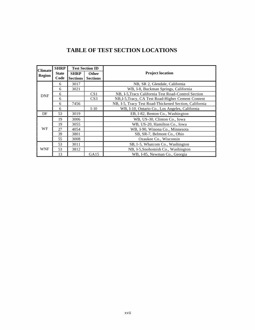
TABLE OF TEST SECTION LOCATIONS
Test Section ID Climate Region
SHRP State Code
SHRP Sections
Other Sections
Project location
6 3017 NB, SR 2, Glendale, California 6 3021 WB, I-8, Buckman Springs, California 6 CS1 NB, I-5,Tracy California Test Road-Control Section 6 CS3 NB,I-5,Tracy, CA Test Road-Higher Cement Content 6 7456 NB, I-5, Tracy Test Road-Thickened Section, California
DNF
6 I-10 WB, I-10, Ontario Co., Los Angeles, California DF 53 3019 EB, I-82, Benton Co., Washington
19 3006 WB, US-30, Clinton Co., Iowa 19 3055 WB, US-20, Hamilton Co., Iowa 27 4054 WB, I-90, Winona Co., Minnesota 39 3801 SB, SR-7, Belmont Co., Ohio
WF
55 3008 Ozaukee Co., Wisconsin 53 3011 SB, I-5, Whatcom Co., Washington 53 3812 NB, I-5,Snohomish Co., Washington WNF 13 GA15 WB, I-85, Newman Co., Georgia
1
INTRODUCTION Background Many portland cement concrete (PCC) pavements on the Interstate highway system have met or exceeded their original design lives (about 20 years). In many cases, the good performing pavements have carried more than twice their design traffic. The good performance has been manifested by no or very low chemical and physical deterioration and structural distresses, in particular near joints and free edges. In 1991, Washington State Department of Transportation investigated two urban Interstate PCC pavement sections along State Road (SR) 5 in Seattle and SR 90 in Spokane that had performed exceptionally well (e.g., no cracking or joint faulting). The evaluation showed that the pavement sections had carried 50 percent and 60 percent respectively more Equivalent Single Axle Loads (ESAL’s) than could be expected using the American Association of State Highway and Transportation Official's (AASHTO) Design Guide. This unusually good performance was attributed to good foundation design with excellent drainage, mild environmental conditions, high quality aggregates in the mix, and high inplace concrete strength. On SR 5 the average in-place compressive and tensile (splitting) strengths were 78 MPa (11,406 lbf/in2) and 6.4 MPa (923 lbf/in2) respectively for 102-mm (4-in) diameter cores. Core strength data for SR 90 was 61.4 MPa (8,894 lbf/in2) and 5.2 MPa (752 lbf/in2) in compression and tension, respectively. These values are significantly higher than those typically specified on a paving project (usually in the range of 27.6 MPa (4,000 lbf/in2) in compression), and were probably obtained through fortuitous circumstances at the time of construction (Mahoney et al., 1991). With the large number of older PCC pavements now in service, State Highway Agencies (SHA’s) must consider either rehabilitation or new construction. It would be optimal if the properties that allowed for such excellent performance in Washington could be reproduced in this upcoming work. In concrete applications other than pavements (e.g., bridges, columns for high rise buildings, off shore structures, etc.), there is a trend toward using higher strength. Design strengths of 55 to 75 MPa (8,000 to 11,000 lbf/in2) or higher have been utilized with success. The advantages of using high strength concrete (HSC) in structural applications are well understood, as the structural demand on the material is high. In pavements, however, the advantage of higher-strength is less obvious. For this reason, strength is being used only as a measure to indicate which pavements might perform better than others. The focus of this study is the material response of the concrete, and not the structural performance of the pavement system.

2
Project Objectives The main objective of this project is to determine the effect of the concrete quality on pavement performance, specifically the effect of increasing strength and altering associated properties. In many current paving specifications quality is defined by flexural strength, compressive strength, and air content. It is possible that PCC properties other than strength and air content may prove to be good or better indicators of improved long-term performance of concrete pavements. To fulfill the research needs described above, the Federal Highway Administration (FHWA) initiated this project in October 1995. The overall objectives are to: 1. Determine the properties of portland cement concrete of higher strength found in certain
inservice pavements which resulted in exceptional long-term performance, particularly as evidenced in freedom from distress near joints and free edges.
2. Identify test methods to measure (quantify) these properties. Also, determine the
material characteristics of the concrete constituents and their proportions, which are responsible for the levels of these properties found in the concrete.
3. Develop, if necessary, revised mix design procedures including any additional fresh or
hardened concrete tests, and develop recommendations for mix designs that will result in the production of concrete for use in pavements that would possess these properties while still meeting current construction requirements and economic considerations.
Project Phases The work conducted in this project can be divided into three phases. The first phase of the project consisted of three parts. The first part was a comprehensive state-of-the-art literature review on important PCC properties, their apparent relation to the PCC pavement performance and PCC mix characteristics. The second part of phase one was an evaluation of the Strategic Highway Research Program’s (SHRP) Long Term Pavement Performance (LTPP) database for PCC pavements of higher strength and their durability performance near joints and cracks. Finally, the third part was to identify and select up to 12 test sections throughout the United States, from primarily excellent performing concrete pavements, for inservice pavement evaluation. The second phase consisted of performing and evaluating field tests and condition surveys of each of the selected test sections. At the University of Michigan (U of M), Michigan
3
Department of Transportation (MDOT), and the Michigan Technological University (MTU) laboratories the PCC properties and material characteristics were measured and determined through standardized and systemized testing procedures. The third phase was mainly development of recommendations based on the field results and any additional laboratory testing of pavement concretes. The field results were evaluated to identify the required levels of PCC properties and their material characteristics in order to obtain excellent pavement concrete. In addition, controlled laboratory investigations were performed on standard pavement concrete mixes to further establish trends and to fill gaps not answered by field testing. Advisory Panel An advisory panel consisting of experienced pavement engineers was assembled to provide guidance to the research team in the collection and evaluation of the PCC properties and material characteristics, and the PCC pavement performance. Members of the advisory panel were: Dr. Jamshid M. Armaghani, Florida Department of Transportation Mr. Bill Cape, James Cape & Sons Mr. Larry Cole, American Concrete Pavement Association Mr. Jim Grove, Iowa Department of Transportation Mr. Robyn Moore, Washington Department of Transportation Mr. Elias H. Rmeili, Texas Department of Transportation, and Mr. David L. Smiley, Michigan Department of Transportation Overview of the Report The results of this project are presented in this final report along with appendixes (separate volume). This report consists of eight chapters. Chapter 1 summarizes the comprehensive literature review of important PCC properties, and their apparent relation to the PCC pavement performance and PCC mix characteristics. It also summarizes an evaluation of the LTPP database for PCC pavements of higher strength and their durability performance near joints and cracks. Chapter 2 presents the outline and methodology for field site selection. Experimental procedures for field and laboratory evaluation of the selected pavements are also presented. Chapter 3 includes a brief site description of each investigated test section, a description of the PCC on a petrographic level, and a presentation of summary data tables obtained from the laboratory tests. Chapter 4 presents an evaluation of the field distress and its causes for the various test sections. Links are made between distress types and concrete properties, and mix characteristics and pavement design factors. The PCC property results from the testing on field

4
concretes are analyzed and discussed in chapter 5. Chapter 6 presents the PCC material characteristics that resulted in the concrete properties reported in chapter 5. Chapter 7 presents the development of project recommendations.

5
CHAPTER 1. LITERATURE REVIEW SUMMARY ON “EFFECTS OF INCREASING CONCRETE STRENGTH AND ASSOCIATED
PCC PROPERTIES ON LONG-TERM PAVEMENT PERFORMANCE”
1.1 Introduction In order to determine the role of the concrete on jointed plain concrete pavement (JPCP) performance it must be realized that a pavement structure is a complex system with many interacting components (e.g. Forster, 1997, and Smith et al., 1997). Pavement performance depends not only on traffic loading, portland cement concrete (PCC) properties and environmental factors (which determine exposure conditions such as freeze-thaw and moisture effects on the concrete over time); but it also depends on the influence of subgrade support and subsurface drainage. It is generally recognized that higher strength concrete with its improved mechanical properties (compressive, tensile, elastic modulus) and more impervious pore system performs better than normal strength concrete in certain structural applications. These applications pertain to structures such as bridges, high rise buildings, off shore structures, etc. However, it is not clear whether this type of concrete is the answer to improved performance in pavement applications. Design compressive strength in structural applications for higher strength concrete is often 55 MPa to 75 MPa or higher. There is very little information in the literature on the performance of higher strength concrete in pavements. 1.2 PCC Properties and Material Characteristics for European Higher Strength JPCP It is current European practice to construct JPCP’s of higher strength concrete compared to JPCP’s in the United States. European state highway agencies have for years used higher strength concrete for pavement applications with design compressive strength typically ranging from 35 to 45 MPa. To better understand the role of concrete strength and durability factors on JPCP performance, the FHWA conducted a field tour of selected European pavements. The major findings are documented in a series of FHWA reports based on a 1992 US tour of European Concrete Pavements (e.g. FHWA-SA-93-012-1992; Till et al., 1994; Smiley, 1995,1996, and 1997; Weinfurter et al., 1994; Larson et al., 1993). This section briefly discusses the observations made on the tour in 1992, and it presents the first US JPCP test section constructed specifically using European construction practices adapted to US conditions.
6
1.2.1 Required Levels of PCC Properties and Material Characteristics Table 1.2.1 lists the JPCP design requirements for concrete properties and material characteristics for eight European countries in wet freeze (WF) and wet no freeze (WNF) climate regions. In addition, requirements are given for pavement and base type. The concrete requirements are shown for the 28-day compressive strength, 28-day flexural strength, water/cement (w/c) ratio, cement content, aggregate gradations, cement types, mix proportions, and air content. Not all eight countries have requirements for all parameters. It should be noted that table 1.2.1 represents design requirements from the early 1990’s and revisions may have occurred. Table 1.2.1 shows that the European countries have similar requirements for compressive strength with the exception of Norway which requires strength values from 45 to 75 MPa. However, a wide spread is seen in the flexural strength requirements ranging from 4.3 to as high as 7.0 MPa. The typical value is around 5.0 MPa. The requirements for w/c ratio are between 0.40 and 0.50, while the cementitious contents range from 300 to 350 kg/m3. Most of the countries allow for cementitious substitutions using slag and fly ash. In Germany fly ash is usually not used due to its variability. The concrete must be freeze-thaw resistant with air contents of 3 to 7 percent. Finally, Germany and France have requirements for the aggregate gradations. It is noteworthy that the mix proportions are typically based on trial mixes. Finally, it should be emphasized that only Norway allows the use of granular bases, and that Germany only allows for bonded cement bases. The German “autobahn” has for decades been considered to be the best European highway, which has been a result of high quality control. For instance, the minimum specified 28-day strength (as determined on 20-cm cubes) is 35 MPa. Normally, as in most US pavements, the field strength substantially exceeds minimum requirements. In a two-layer pavement the compressive strength is often 65 MPa in the top layer and 50 MPa for the bottom layer. Furthermore, the maximum w/c ratio is 0.42, the minimum cement content is 349 kg/m3, and the air content is typically about 5 percent. A 5-m joint spacing is used with variably spaced, plastic coated dowel bars. An important feature of the German pavement cross section is the use of a 15-cm lean concrete (LCB) or cement treated base (CTB). Special for the German design is that the CTB is bonded to the slab, thereby achieving a thicker monolithic slab for several years after construction. To prevent reflection cracking, the CTB is pre-notched to match the transverse joint in the slab. To decrease edge stress the concrete pavement extends 0.5 m beyond the traffic lane. 1.2.2 European Concrete Pavement Demonstration Project in Michigan Based on the European design catalogs, an experimental higher strength rigid pavement section was constructed in Detroit, Michigan, in 1993. The test road was designed as a premium JPCP based on the German design guidelines for the local climate, soil, and traffic conditions. The project used high quality concrete aggregate and higher than normal concrete strengths combined with a nonerodible lean concrete base to limit slab deflections (Larson et al., 1993, Till et al., 1994).
7
The test road is located on I-75, in downtown Detroit, Michigan. Also known as the Chrysler freeway located between I-375 and the I-94 freeways, this section is one of Michigan’s busiest freeways carrying about 111,000 vehicles a day, of which about 11 percent are trucks. The test pavement is about 1.6 km long. For comparison, a conventional Michigan pavement design was used for the remaining project, which is a jointed reinforced concrete pavement (JRCP), and therefore has much longer joint spacing as compared to the JPCP European pavement (4.57 m). Two typical Michigan JRCP slab designs were used with joint spacings of 12.5 m and 8.23 m. As a result of the longer slab lengths, these panels are expected to develop tight mid-slab transverse cracks or one-third panel cracks within a few years after construction. A reinforcing mesh placed in the middle of the slab of the Michigan design is then used to hold the crack tight such that good load transfer across the crack is maintained. If a crack opens beyond about 0.6 mm the aggregate interlock is significantly reduced and the crack often deteriorates due to spalling and faulting (Hansen et al., 1998) Heavier legal axle loads in Europe require a stronger and more durable pavement. In Germany for instance, the single axle load is 13 tons as of 1993 compared to 8.2 tons in Michigan. However, Michigan is the only State in the United States that allows 11 axle trucks with a gross truck weight of 74.5 tons. The Federal weight limit is 36.4 tons.
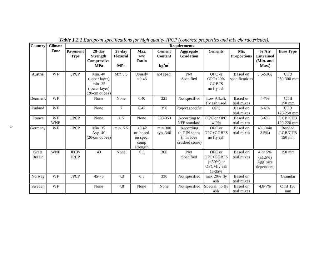
Table 1.2.1 European specifications for high quality JPCP (concrete properties and mix characteristics). Requirements Country Climate
Zone Pavement Type
28-day Strength
Compressive MPa
28-day Flexural
MPa
Max. w/c
Ratio
Cement Content
kg/m3
Aggregate Gradation
Cements Mix Proportions
% Air Entrained (Min. and
Max.)
Base Type
Austria WF JPCP Min. 40 (upper layer)
min. 35 (lower layer)
(20-cm cubes)
Min 5.5 Usually <0.43
not spec. Not Specified
OPC or OPC+20%
GGBFS no fly ash
Based on specifications
3.5-5.0% CTB 250-300 mm
Denmark WF None None 0.40 325 Not specified Low Alkali, fly ash used
Based on trial mixes
4-7% CTB 150 mm
Finland WF None 7 0.42 350 Project specific OPC Based on trial mixes
2-4 % CTB 120-250 mm
France WF WNF
JPCP None > 5 None 300-350 According to NFP standard
OPC or OPC w Pfa
Based on trial mixes
3-6% LCB/CTB 120-220 mm
Germany WF JPCP Min. 35 Avg. 40
(20-cm cubes)
min. 5.5 <0.42 or based on spec.
comp strength
min 300 typ. 340
According to DIN specs
(min 50% crushed stone)
OPC or OPC+GGBFS
no fly ash
Based on trial mixes
4% (min 3.5%)
Bonded LCB/CTB 150 mm
Great Britain
WNF JPCP/ JRCP
40 None 0.5 300 Not Specified
OPC or OPC+GGBFS
(<50%) or OPC+fly ash
15-35%
Based on trial mixes
4 or 5% (±1.5%)
Agg. size dependent
150 mm
Norway WF JPCP 45-75 4.3 0.5 330 Not specified max 20% fly ash
Based on trial mixes
Granular
Sweden WF None 4.8 None None Not specified Special, no fly ash
Based on trial mixes
4.8-7% CTB 150 mm
8
9
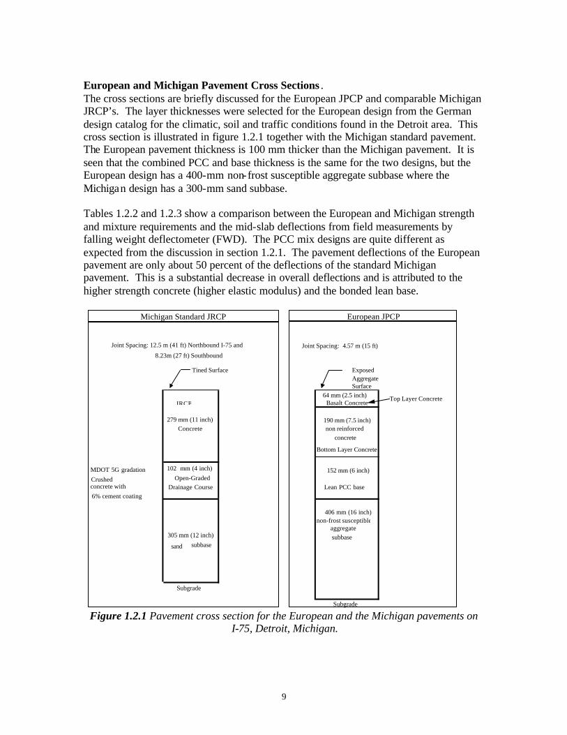
European and Michigan Pavement Cross Sections . The cross sections are briefly discussed for the European JPCP and comparable Michigan JRCP’s. The layer thicknesses were selected for the European design from the German design catalog for the climatic, soil and traffic conditions found in the Detroit area. This cross section is illustrated in figure 1.2.1 together with the Michigan standard pavement. The European pavement thickness is 100 mm thicker than the Michigan pavement. It is seen that the combined PCC and base thickness is the same for the two designs, but the European design has a 400-mm non-frost susceptible aggregate subbase where the Michigan design has a 300-mm sand subbase. Tables 1.2.2 and 1.2.3 show a comparison between the European and Michigan strength and mixture requirements and the mid-slab deflections from field measurements by falling weight deflectometer (FWD). The PCC mix designs are quite different as expected from the discussion in section 1.2.1. The pavement deflections of the European pavement are only about 50 percent of the deflections of the standard Michigan pavement. This is a substantial decrease in overall deflections and is attributed to the higher strength concrete (higher elastic modulus) and the bonded lean base.
Michigan Standard JRCP European JPCP
Joint Spacing: 12.5 m (41 ft) Northbound I-75 and Joint Spacing: 4.57 m (15 ft)8.23m (27 ft) Southbound
Tined Surface ExposedAggregateSurface
64 mm (2.5 inch) Top Layer ConcreteBasalt Concrete
279 mm (11 inch) 190 mm (7.5 inch)Concrete non reinforced
Bottom Layer Concrete
concrete
MDOT 5G gradation 102 mm (4 inch) 152 mm (6 inch)Crushed Open-Graded
Lean PCC baseconcrete with Drainage Course6% cement coating
406 mm (16 inch)non-frost susceptible
aggregate305 mm (12 inch) subbase
sand subbase
Subgrade
Subgrade
JRCP
Figure 1.2.1 Pavement cross section for the European and the Michigan pavements on
I-75, Detroit, Michigan.

10
Table 1.2.2 Midslab maximum deflection from FWD on I-75, Detroit. Deflections Inside Lane Middle Lane Outside Lane
(mm) European Michigan European Michigan European Michigan Average 0.03 0.06 0.03 0.05 0.03 0.05
Maximum 0.04 0.07 0.04 0.06 0.04 0.06 Minimum 0.03 0.05 0.03 0.05 0.03 0.05
Table 1.2.3 Strength and mix requirements for the European and the Michigan
pavements on I-75, Detroit. European Test Pavement
Property Top Layer Bottom Layer Lean Base
Michigan Control
Pavement 28-day Compressive Strength, MPa
(lbf/in2) 37.9
(5500) 34.4
(5000) 17.2
(2500) 24.1
(3500) 28-day Flexural Strength, MPa
(lbf/in2) None None None 4.50
(650) Maximum w/c 0.40 0.42 0.70 0.50
Minimum Cement Content, kg/m3 (lb/yd3)
446 (752)
349 (588)
249 (420)
326 (550)
Maximum Slump , mm (in)
76 (3)
76 (3)
76 (3)
76 (3)
Air Content (±1.5%) 6.5 6.5 6.5 6.5
Preliminary Conclusions MDOT is monitoring the test sections for up to 5 years for the FHWA. Conclusions based on construction experience and first 5 years of service life are: • Construction of the European pavement design occurred without any major problems.
More familiarity with placing the two-layer concrete mixtures and the exposed aggregate surface would result in faster construction and may reduce cost.
• The top concrete layer should not be less than 7 cm in thickness to avoid poor consolidation and thin surface layer.
• The top layer should not have sand particles larger than 1 mm to allow the coarse aggregate with a nominal diameter of 6-8 mm to lock together better when there is an exposed surface. The coarser sand wears faster than the basalt coarse aggregate, and closer packing is expected to reduce tire noise level.
• Both pavement types are performing as expected. There are no transverse cracks in the short panels of the European pavement, whereas about 28 percent of the Michigan JRCP 12.5 m panels have either one mid panel crack or two transverse cracks at the panel’s third points. The cracks are equally scattered across all lanes. This initial crack pattern is typical of Michigan’s JRCP’s.
This demonstration project has not yet had sufficient traffic and environmental exposure time to warrant a detailed field and laboratory investigation in this study. However, since the demonstration project, MDOT has developed new design and construction requirements to improve long-term pavement performance. MDOT has modified its concrete pavement mixture to include large size coarse aggregate (62-mm
11
top size) with lower freeze-thaw dilation values and limits on specific gravity and absorption. MDOT has also included tighter requirements on construction methods for sawing joint relief cuts and allowable concrete mixture temperatures during placement. Furthermore, MDOT now mandates a warranty from the prime contractor on all new or reconstruction projects involving concrete paving. The warranty is a materials and workmanship warranty with condition thresholds on surface distresses. 1.3 Trends in Pavement PCC from the LTPP Database The LTPP database was originally established by Strategic Highway Research Program (SHRP). As will be detailed in chapter 2, the LTPP database contains a large amount of data from over 200 concrete pavement sites across the United States and Canada. In order to establish overall performance and practice trends, the LTPP database was reviewed as part of this study with special attention given to JPCP pavements (subgroup GPS3 in the LTPP database). This evaluation was done prior to field-testing, and as discussed in chapter 2 of this report, the LTPP database has been used extensively to select the JPCP test sections for detailed analysis in this study. Sections were selected from LTPP which had shown primarily excellent long-term performance (more than 20 years), or which had high or low PCC strength. 1.3.1 Regional PCC Trends in the LTPP Database There are both general regional trends in the PCC mixture parameters and properties and clear State to State trends (Byrum et al., 1997; and Hansen et al., 1998a). The general trends are likely related to the evolution of PCC mixtures within regions due to different paving conditions. Regions, which are generally hot, such as the southwest and southeast, have evolved mixes that use higher w/c ratio. This general trend may have evolved to ensure adequate workability in such hot conditions. There is also common use of type II low heat of hydration cement in the warmer regions of the southwest and along the West Coast in general. Regions which have considerable freeze thaw cycles, such as the upper mid-west appear to have evolved mixes which have more paste volume with low w/c ratio and higher air and cement contents. Nonfreeze regions that are also cooler and have good aggregates, such as Washington State, have evolved the highest strength mixes. This combination typically results in both high strengths and high stiffness. Similar to the Washington State mixes are the California mixes. These mixes have low paste volume, low air, and high strength aggregate. However, they use high mix water contents and w/c ratio. These mixes often have properties of higher split tensile strength and lower stiffness than would be expected for average concrete. Mixes used in Georgia and Florida have properties of average paste volume, high w/c ratio, and low to medium aggregate strength. The result is a PCC with lower strength and stiffness. Wisconsin PCC uses very high paste volume with low w/c ratio and high air content and lower aggregate strength. This results in higher stiffness and compressive strength but not necessarily higher splitting tensile strength. State to State variations are likely based on variations in SHA mixture specifications and design methodology, variations in primary aggregate types within each state, and variations in placement and curing specifications.
12
1.3.2 Preliminary Performance Trends in the LTPP Database A preliminary review of the effects of PCC strength on pavement performance levels in LTPP indicates that the primary pavement deterioration mechanisms are hidden within the foundation layer properties and climate/traffic parameters. This observation warrants a detailed field investigation in order to isolate the effects and the mechanisms of PCC on JPCP deterioration from foundation and environmental factors. Modeling of faulting, spalling, and transverse cracking using the LTPP database has been performed by several researchers in the last 5 years (e.g. Byrum et al., 1997; and Titus-Glover et al., 1999). These models do incorporate the effect of PCC properties on distress development. Yet, further model improvement must be made if the effect of PCC strength and associated properties on long-term pavement performance is to be better understood. In general, higher strength concrete may be more sensitive to use in pavement applications. For example, high strength mixes may be more susceptible to developing slab curling. This phenomenon is related to increased PCC elastic modulus. Therefore, extra care must be taken when using higher strength concrete in pavement applications to ensure that a "flat slab" condition is obtained. It appears that if the initial sensitivity can be overcome by stricter temperature control and curing specifications, pavement deterioration will be slower and less severe for higher strength concrete. While the LTPP database is an excellent tool for developing general trends about performance, it is less effective in evaluating the causes of distress or distress free behavior under specific conditions. This is because such performance can be masked by a multitude of other factors that are not directly evident in the LTPP database. Thus field and laboratory evaluation of selected pavement sections is an indispensable part of this research. 1.4 Concrete Properties with Significant Influence on Jointed Concrete Pavement Performance In view of the limited number of studies and data available on the effect of higher concrete strength and associated properties on long-term JPCP performance, the literature review focused on the main JPCP variables that affect pavement performance. The JPCP variables to be evaluated include design factors, environmental factors, and concrete properties. However, the review emphasis will still be toward identifying and categorizing the PCC properties that affect JPCP distress development. It is important to keep in mind that the concrete properties and mix characteristics often are not the factors controlling distress initiation. However, they can often be mitigating factors in delaying the distress development.

13
Concrete pavement design for JPCP’s is based on field-calibrated mechanistic design procedures. The design procedures include the pavement response calculated from structural models, durability requirements, distress models to predict the development of distress from the structural response, and distress calibration factors to predict the distresses observed in the field (e.g. PCA, 1984; AASHTO, 1986; and ACI 360R, 1992). The distress models include fatigue cracking models, pumping erosion models, faulting models, and joint deterioration models (e.g. NCHRP Report 1-26, 1990; Van Wiji et al., 1989; Darter et al., 1991; and Titus-Glover et al., 1999). These models include a large number of design factors, environmental factors, and PCC properties. Table 1.4.1 shows the significant independent variables affecting the various JPCP distresses. These distresses are joint faulting, spalling, transverse cracking and corner breaks. The variables range over design parameters, environmental factors, and PCC properties. The parameters in normal font were also found in a study reported by Owusu and Darter (1994), and the parameters added in italic are additional parameters, which were identified in this literature review. Table 1.4.1 shows that a large number of variables (33) affects pavement distress. This illustrates the complexity and difficulty in quantifying the effects of the individual parameters on pavement performance. The focus of this study is to extract and evaluate the effect of increasing concrete strength and associated properties on pavement performance with emphasis on good long-term performance. Thus, factors leading to premature distress are not emphasized in this study. The PCC properties affecting distress are listed in bold in table 1.4.1, and it is seen that the properties typically affect more than one distress type. As stated in section 1.3 the effect of PCC properties on pavement distress is often difficult to quantify as factors such as traffic, age, environment, and foundation dominate the overall pavement behavior. Traditionally, PCC properties are not included in faulting models because factors related to the pavement foundation, traffic, and environmental exposure play primary roles in distress development. Spalling is highly related to PCC durability. The traditional models for prediction of spalling include PCC factors such as D-Cracking and alkali silica reaction (ASR), but not factors such as air void system and permeability. Other prime design factors are traffic, age, and joint spacing.
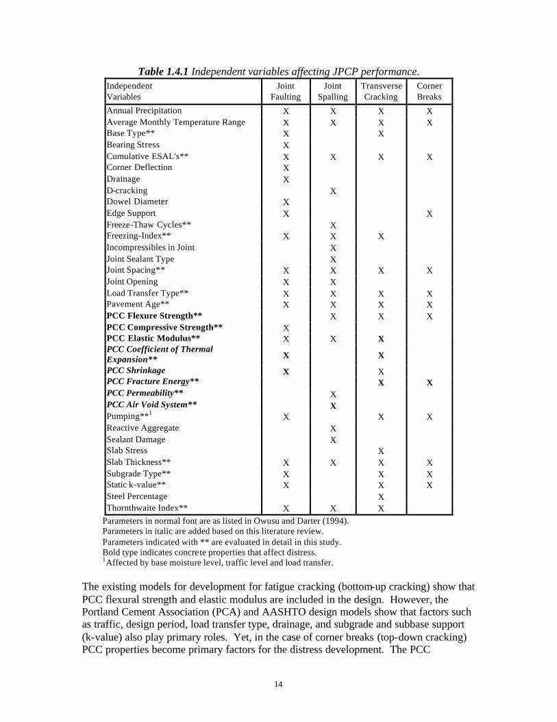
14
Table 1.4.1 Independent variables affecting JPCP performance. Independent Variables
Joint Faulting
Joint Spalling
Transverse Cracking
Corner Breaks
Annual Precipitation X X X X Average Monthly Temperature Range X X X X Base Type** X X Bearing Stress X Cumulative ESAL's** X X X X Corner Deflection X Drainage X D-cracking X Dowel Diameter X Edge Support X X Freeze-Thaw Cycles** X Freezing-Index** X X X Incompressibles in Joint X Joint Sealant Type X Joint Spacing** X X X X Joint Opening X X Load Transfer Type** X X X X Pavement Age** X X X X PCC Flexure Strength** X X X PCC Compressive Strength** X PCC Elastic Modulus** X X X PCC Coefficient of Thermal Expansion** X X
PCC Shrinkage X X PCC Fracture Energy** X X PCC Permeability** X PCC Air Void System** X Pumping**1 X X X Reactive Aggregate X Sealant Damage X Slab Stress X Slab Thickness** X X X X Subgrade Type** X X X Static k-value** X X X Steel Percentage X Thornthwaite Index** X X X
Parameters in normal font are as listed in Owusu and Darter (1994). Parameters in italic are added based on this literature review. Parameters indicated with ** are evaluated in detail in this study. Bold type indicates concrete properties that affect distress. 1Affected by base moisture level, traffic level and load transfer.
The existing models for development for fatigue cracking (bottom-up cracking) show that PCC flexural strength and elastic modulus are included in the design. However, the Portland Cement Association (PCA) and AASHTO design models show that factors such as traffic, design period, load transfer type, drainage, and subgrade and subbase support (k-value) also play primary roles. Yet, in the case of corner breaks (top-down cracking) PCC properties become primary factors for the distress development. The PCC
15
properties determine the onset of crack initiation and the propagation of full width cracking. The following sections discuss the key variables affecting faulting, spalling, and transverse cracking. 1.4.1 Crack and Joint Faulting Faulting is a vertical offset of adjacent slabs at joints or cracks. Faulting and the development of faulting have been observed and investigated by many researchers. It is well-known that a pavement slab will develop severe faulting if the following four conditions occur simultaneously: the joint or crack experiences poor load transfer, heavy traffic is present, free water is present in the slab-base interface, and the base layer is erodible (e.g. Titus-Glover et al., 1999). Faulting Models Faulting has traditionally been evaluated through empirical models. The empirical models include the combination of variables that affect the development of faulting (e.g. Darter et al., 1985; and Simpson et al., 1994). The models include some or all of the following parameters: accumulated traffic load, slab thickness, joint spacing, base type, freezing index, precipitation, edge support, pumping, drainage type, load transfer system, and modulus of subgrade reaction. Note that PCC properties are not directly included in these empirical models. For detailed and mechanistic distress analysis the PCC properties and characteristics need to be included. However, it should be noted that PCC compressive strength is included in dowel design (Huang 1993). PCA developed a mechanistic-empirical model to predict erosion damage at slab corners. This model was based on Miner’s damage model of the work induced by traffic load. The model included the expected number of load repetitions, the pressure at the slab-foundation interface, the slab thickness, and the modulus of subgrade reaction. Recently, Titus-Glover et al. (1999) developed another mechanistic-empirical faulting model. The model is based on the concept of differential elastic deformation energy at the crack or joint and incorporates the four prime factors affecting faulting development that were listed previously. The model also incorporates PCC elastic modulus for determining the slab deflections and aggregate interlock. Crack and Joint Load Transfer Load transfer efficiency across a crack or joint is controlled by the aggregate interlock, slab stiffness, foundation stiffness, and dowels if any. When cracks develop in JPCP, the structural integrity is only maintained through aggregate interlock aided by compressive stresses (closing forces) that may be present in the slab plane. The vertical stresses are transferred through the aggregate interlock, slab stiffness, and elastic deformation of the sublayers. Traditionally, the effectiveness of aggregate interlock is measured using the load transfer efficiency, LTE. The LTE is quantified by a relative measure of the deflections on either side of the crack or joint, and several models have been developed for quantifying LTE based on slab deflections (e.g. Benkelman, 1933; Teller and
16
Sutherland, 1936; and Ioannides and Korovesis, 1990). According to the model proposed by Ioannides and Korovesis, LTE is the ratio between the unloaded and the loaded side of the crack. An LTE value of 60 percent is considered the lower limit for medium to heavy truck traffic (Smith et al., 1990). The mechanism responsible for transferring stresses from the loaded slab segment to the unloaded segment across a crack in a JPCP is rather complex. The mechanism is influenced by crack width, aggregate size and type, slab thickness, slab length, the friction coefficient between the slab and the base, and the magnitude and repetition of the load. Aggregate interlock provides the shear resistance along the fractured surface. As a load is applied on one side of the crack, vertical deflections of the slab will cause the two crack faces into contact. The opposing crack face will resist the shear loading through bearing and friction of the coarse aggregate along the crack. When a crack is formed in normal strength concrete containing strong coarse aggregate, the majority of the coarse aggregate particles remain embedded in the mortar on either side of the crack. The aggregate/mortar interface zone strength is lower than that of the coarse aggregate, resulting in cracking around the coarse aggregate and forming a rough irregular crack surface. However, if the coarse aggregate is weaker than that of the interface zone, the crack will penetrate through the aggregate resulting in a straight and smoother crack surface. Section 1.5.8 will discuss the coarse aggregate characteristics that affect the load transfer mechanism. Evaluation of visual distress surveys made in the field shows that the crack widths of the individual cracks vary from hairline to about 1 mm for nondeteriorated transverse cracks. For spalled cracks, the surface crack width is difficult to measure and it is likely very large (e.g. Hansen et al., 1998). Colley and Humphrey (1967) showed for un-doweled pavements that LTE decreases as the joint opening increases. This trend was found in both field and laboratory tests. Hansen et al. obtained the same trend for Michigan JRCP’s. Furthermore, Colley and Humphrey showed that for a given crack width, LTE decreases with the number of load repetitions, reaching a plateau determined by the overall system response. Hansen et al. (1998) evaluated LTE versus crack width for jointed concrete pavements (JCP’s) containing different types of coarse aggregates. All sections with gravel and carbonated aggregate showed high and sufficient LTE’s ranging from 75 to 100 percent for crack widths smaller than approximately 0.6 mm. This field study also showed that for an increased crack width, in addition to decreasing LTE, the deflection on the loaded slab segment increased significantly. Joint Opening The joint load transfer decreases with increasing joint opening. Therefore, an accurate estimate of the joint opening is essential to decide if a dowel system is required at a JPCP joint, or whether aggregate interlock will be sufficient in transferring the wheel loads. For nondoweled JPCP, a joint opening of 0.75 mm is considered as the maximum limit
17
above which aggregate interlock is insufficient (Kelleher, 1989). This agrees with field and laboratory studies indicating that crack load transfer efficiency typically falls below an acceptable limit for crack widths larger than 0.60 to 0.75 mm (e.g. Colley and Humphrey, 1967; and Hansen et al., 1998). Joint movement is also a critical factor in the design of a joint sealant as proper design of sealant can significantly reduce joint deterioration. The joint width controls the amount of compression exerted on the sealant during expansion and contraction of the slab. A compressive stress less than the required minimum will provide easy passage for water, while a compression stress beyond the allowable maximum may damage the sealant. According to Darter and Barenberg (1977), the relationship between joint opening and change in temperature can be written as:
( )ε+∆⋅⋅=∆ TCTELCL (1.4.1) where ∆L = joint opening (mm).
C = adjustment factor for slab-subbase friction. L = slab length (mm). ∆T = maximum temperature range (temperature at placement/setting time minus
lowest mean monthly temperature) (°C). CTE= PCC coefficient of thermal expansion (/°C). ε = PCC shrinkage coefficient (mm/mm).
The PCC coefficient of thermal expansion and shrinkage are highly dependent on the cement paste content and the aggregate type and content. It should also be emphasized that parameters such as slab length and placement temperature can become very important for climatic zones with very low winter temperatures. If dowels are needed at the joints, the PCC compressive strength becomes important in determining the overall joint design (dowel diameter and spacing, etc.) Summary Based on field investigations and faulting models, the key PCC properties affecting faulting include elastic modulus, compressive strength, coefficient of thermal expansion, and shrinkage. In addition, it was found that the coarse aggregate type and size as a PCC mix characteristic is very important for LTE and in turn for the development of faulting. 1.4.2 Crack and Joint Spalling Spalling is the deterioration and breaking up of the concrete at longitudinal and transverse edges, joints, and cracks. Spalling is a general term and can be the ultimate manifestation of many forms of deterioration such as freeze-thaw damage, D-cracking, alkali silica reaction (ASR), and poor construction procedures. It should be mentioned that accelerated and severe spalling has been related to D-cracking and ASR susceptible aggregate sources. It is well known that increasing and enhancing the PCC air void system improves the PCC pavement performance in terms of less surface scaling, better sulfate resistance, and less cracking related to alkali-silica reactivity (Kosmatka and
18
Panarese, 1988). Several detailed studies have documented the D-cracking and ASR phenomena and they are not the focus of this research (e.g. Marks, 1990; Stark, 1991; and SHRP-P-338, 1993). Furthermore, the transportation of fluids into and out of the concrete is also an important mechanism responsible for deterioration and poor performance (Roy et al., 1995). PCC permeability is considered the best parameter to access long-term durability, or in other words the ability of the concrete to resist deterioration (Schonlin and Hilsdorf, 1988; and Armaghani et al., 1994). Field studies have shown that coarse aggregate type has been found to relate to concrete spalling. Spalling of continuous reinforced concrete pavements (CRCP’s) was investigated and it was found that siliceous gravel mixes had much greater spalling potential than crushed limestone mixes (Senadheera and Zollinger, 1996). Furthermore, a Michigan study found that blended aggregates had highly variable performance (e.g. mix of siliceous and carbonated sources) (Holbrook and Kuo, 1974). In addition, other field studies indicate that the aggregate-matrix bond at an early age is a very important factor in spalling development. The aggregate-matrix bond has typically been evaluated through flexural and tensile strength (Fowler et al., 1996). Spalling Models Several empirical models have been proposed for the development of joint spalling. The models generally include parameters such as age, freeze-thaw cycles, ambient temperatures, moisture index, joint spacing, slab thickness, joint opening, joint sealant type, drainage, modulus of subgrade reaction, and concrete elastic modulus (e.g. Simpson et al., 1994; and Yu et al., 1996). Spalling can also occur due to traffic loading. The mechanism behind this type of spalling is not yet fully understood. However, it is known that loads generally increase the severity and magnitude of spalling. Furthermore, it appears that more movement (either horizontal or vertical) at a crack or joint generally leads to more rapid spalling development. It is typical that during the first few pavement service years, there is almost no development of joint spalling. However, when the deterioration does initiate it usually develops very rapidly. This indicates that spalling can be predicted as a fatigue phenomenon. Titus-Glover et al. (1999) developed a load based mechanistic-empirical model for slab spalling. The static model is based on the mode of spalling initiation and propagation proposed by Senadheera and Zollinger (1995). The model incorporates concrete properties such as tensile strength, elastic modulus, thermal expansion, and drying shrinkage. Other parameters in the model are tire configuration, tire shear stress, concrete friction coefficient, joint compressive stresses, slab-base friction coefficient, slab thickness, joint spacing, and modulus of subgrade reaction.

19
Summary In summary, key PCC properties affecting spalling are elastic modulus, air void system and permeability. In addition, it was found that the early age aggregate-matrix bond is very important for the development of spalling, and it can be evaluated through PCC flexural and tensile strength. 1.4.3 Transverse Cracking and Corner Breaks Since the 1930’s researchers have worked towards understanding, predicting, and modeling transverse cracks and joints in PCC slabs on grade. The work has ranged from field investigations, field-calibrated prediction models, laboratory investigations, and numerical modeling of the crack or joint behavior. Transverse cracks are expected to develop in continuous and jointed reinforced concrete pavements (CRCP and JRCP) due to the combined effect of concrete volumetric changes, and mechanical and environmental loading. However, transverse cracks are not expected or desirable in JPCP’s. Structural behavior of the pavement system and the fatigue strength of the concrete affect transverse cracking (e.g., Bradbury, 1938; Vesic and Saxena, 1969; Darter 1977; Darter and Barenberg, 1977; Packard and Tayabji 1985; Salsilli et al., 1993, and Titus-Glover et al., 1999). The concrete properties affecting the slab response are tensile strength, elastic modulus, fatigue life, coefficient of thermal expansion, and shrinkage. This suggests that transverse cracking is not durability related, but tends to be associated with the mechanical features of the concrete. It is after the crack formation that durability issues become important, affecting deterioration rates for the cracks. Transverse cracking has traditionally been addressed through the life expectancy of the pavement as it is affected by concrete fatigue due to slab edge loading. Recently a mechanistic approach has been proposed based on the theory of fracture mechanics (Titus-Glover et al., 1999). Fatigue analysis is the classical analysis approach for JCP’s. It pertains to slab response to traffic and thermal loading. Fatigue cracking seldom causes structural failure, but it is important since fatigue cracking initiates cracks that may propagate due to external loads and environmental factors (Gillespie et al., 1993). Figure 1.4.1 shows different support and loading configurations for five plates (Bache and Vinding, 1990/1992). Example E can be related to slab-on-grade and this configuration, along with example D, would initiate cracking at peak load, but the plate would not fail in a catastrophic manner as would the plates in examples A, B, and C. For fatigue cracking of slabs-on-grade, as in example E, it is expected that small hairline cracks are initiated and over time they will develop to full width cracks. PCC fatigue is typically related to PCC flexural strength. PCC fatigue is defined as the stress ratio between applied stress and static flexural strength. Based on beam testing, a very conservative ratio of 0.50 has been suggested by the Portland Cement Association (PCA) if the slab is being subjected to 10 million or more loading cycles. Figure 1.4.2 shows the fatigue results from several beam studies. A recent study on the fatigue of concrete beams and slabs showed that the fatigue resistance was 30 percent higher for
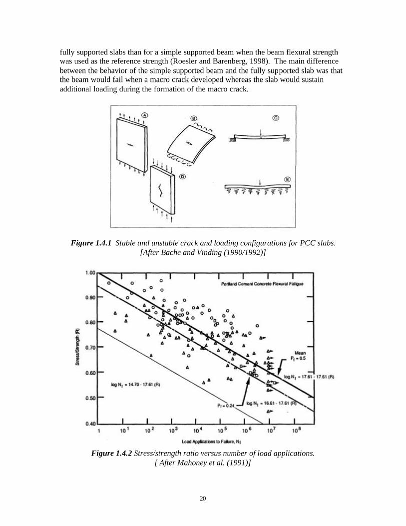
20
fully supported slabs than for a simple supported beam when the beam flexural strength was used as the reference strength (Roesler and Barenberg, 1998). The main difference between the behavior of the simple supported beam and the fully supported slab was that the beam would fail when a macro crack developed whereas the slab would sustain additional loading during the formation of the macro crack.
Figure 1.4.1 Stable and unstable crack and loading configurations for PCC slabs.
[After Bache and Vinding (1990/1992)]
Figure 1.4.2 Stress/strength ratio versus number of load applications. [ After Mahoney et al. (1991)]
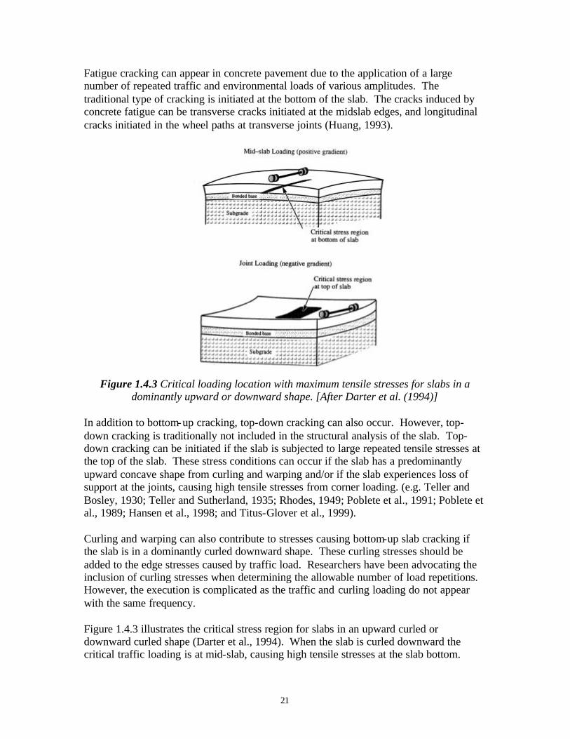
21
Fatigue cracking can appear in concrete pavement due to the application of a large number of repeated traffic and environmental loads of various amplitudes. The traditional type of cracking is initiated at the bottom of the slab. The cracks induced by concrete fatigue can be transverse cracks initiated at the midslab edges, and longitudinal cracks initiated in the wheel paths at transverse joints (Huang, 1993).
Figure 1.4.3 Critical loading location with maximum tensile stresses for slabs in a dominantly upward or downward shape. [After Darter et al. (1994)]
In addition to bottom-up cracking, top-down cracking can also occur. However, top-down cracking is traditionally not included in the structural analysis of the slab. Top-down cracking can be initiated if the slab is subjected to large repeated tensile stresses at the top of the slab. These stress conditions can occur if the slab has a predominantly upward concave shape from curling and warping and/or if the slab experiences loss of support at the joints, causing high tensile stresses from corner loading. (e.g. Teller and Bosley, 1930; Teller and Sutherland, 1935; Rhodes, 1949; Poblete et al., 1991; Poblete et al., 1989; Hansen et al., 1998; and Titus-Glover et al., 1999). Curling and warping can also contribute to stresses causing bottom-up slab cracking if the slab is in a dominantly curled downward shape. These curling stresses should be added to the edge stresses caused by traffic load. Researchers have been advocating the inclusion of curling stresses when determining the allowable number of load repetitions. However, the execution is complicated as the traffic and curling loading do not appear with the same frequency. Figure 1.4.3 illustrates the critical stress region for slabs in an upward curled or downward curled shape (Darter et al., 1994). When the slab is curled downward the critical traffic loading is at mid-slab, causing high tensile stresses at the slab bottom.
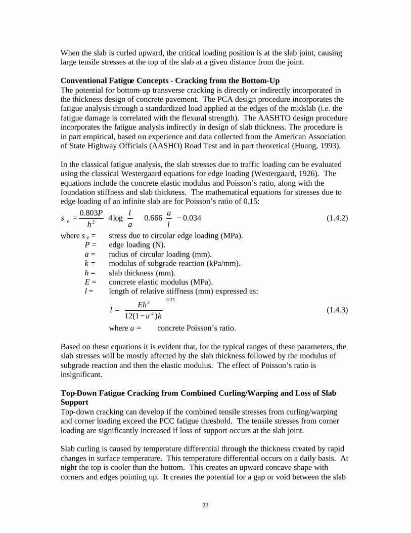
22
When the slab is curled upward, the critical loading position is at the slab joint, causing large tensile stresses at the top of the slab at a given distance from the joint. Conventional Fatigue Concepts - Cracking from the Bottom-Up The potential for bottom-up transverse cracking is directly or indirectly incorporated in the thickness design of concrete pavement. The PCA design procedure incorporates the fatigue analysis through a standardized load applied at the edges of the midslab (i.e. the fatigue damage is correlated with the flexural strength). The AASHTO design procedure incorporates the fatigue analysis indirectly in design of slab thickness. The procedure is in part empirical, based on experience and data collected from the American Association of State Highway Officials (AASHO) Road Test and in part theoretical (Huang, 1993). In the classical fatigue analysis, the slab stresses due to traffic loading can be evaluated using the classical Westergaard equations for edge loading (Westergaard, 1926). The equations include the concrete elastic modulus and Poisson’s ratio, along with the foundation stiffness and slab thickness. The mathematical equations for stresses due to edge loading of an infinite slab are for Poisson’s ratio of 0.15:
−
+
= 034.0666.0log4
803.02 l
aal
hP
eσ (1.4.2)
where σe = stress due to circular edge loading (MPa). P = edge loading (N). a = radius of circular loading (mm). k = modulus of subgrade reaction (kPa/mm). h = slab thickness (mm). E = concrete elastic modulus (MPa). l = length of relative stiffness (mm) expressed as:
25.0
2
3
)1(12
−
=k
Ehl
υ (1.4.3)
where υ = concrete Poisson’s ratio. Based on these equations it is evident that, for the typical ranges of these parameters, the slab stresses will be mostly affected by the slab thickness followed by the modulus of subgrade reaction and then the elastic modulus. The effect of Poisson’s ratio is insignificant. Top-Down Fatigue Cracking from Combined Curling/Warping and Loss of Slab Support Top-down cracking can develop if the combined tensile stresses from curling/warping and corner loading exceed the PCC fatigue threshold. The tensile stresses from corner loading are significantly increased if loss of support occurs at the slab joint. Slab curling is caused by temperature differential through the thickness created by rapid changes in surface temperature. This temperature differential occurs on a daily basis. At night the top is cooler than the bottom. This creates an upward concave shape with corners and edges pointing up. It creates the potential for a gap or void between the slab
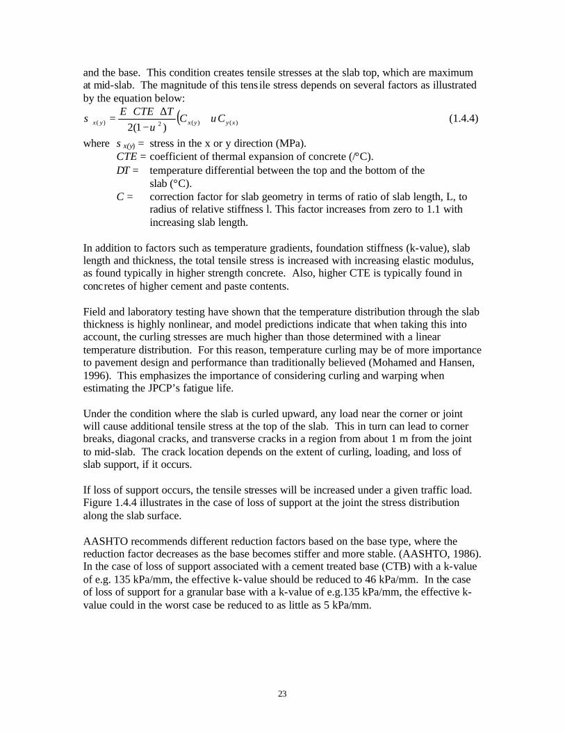
23
and the base. This condition creates tensile stresses at the slab top, which are maximum at mid-slab. The magnitude of this tens ile stress depends on several factors as illustrated by the equation below:
( ))()(2)( )1(2 xyyxyx CCTCTEE
υυ
σ +−
∆⋅⋅= (1.4.4)
where σx(y) = stress in the x or y direction (MPa). CTE = coefficient of thermal expansion of concrete (/°C). ∆T = temperature differential between the top and the bottom of the slab (°C). C = correction factor for slab geometry in terms of ratio of slab length, L, to
radius of relative stiffness l. This factor increases from zero to 1.1 with increasing slab length.
In addition to factors such as temperature gradients, foundation stiffness (k-value), slab length and thickness, the total tensile stress is increased with increasing elastic modulus, as found typically in higher strength concrete. Also, higher CTE is typically found in concretes of higher cement and paste contents. Field and laboratory testing have shown that the temperature distribution through the slab thickness is highly nonlinear, and model predictions indicate that when taking this into account, the curling stresses are much higher than those determined with a linear temperature distribution. For this reason, temperature curling may be of more importance to pavement design and performance than traditionally believed (Mohamed and Hansen, 1996). This emphasizes the importance of considering curling and warping when estimating the JPCP’s fatigue life. Under the condition where the slab is curled upward, any load near the corner or joint will cause additional tensile stress at the top of the slab. This in turn can lead to corner breaks, diagonal cracks, and transverse cracks in a region from about 1 m from the joint to mid-slab. The crack location depends on the extent of curling, loading, and loss of slab support, if it occurs. If loss of support occurs, the tensile stresses will be increased under a given traffic load. Figure 1.4.4 illustrates in the case of loss of support at the joint the stress distribution along the slab surface. AASHTO recommends different reduction factors based on the base type, where the reduction factor decreases as the base becomes stiffer and more stable. (AASHTO, 1986). In the case of loss of support associated with a cement treated base (CTB) with a k-value of e.g. 135 kPa/mm, the effective k-value should be reduced to 46 kPa/mm. In the case of loss of support for a granular base with a k-value of e.g.135 kPa/mm, the effective k-value could in the worst case be reduced to as little as 5 kPa/mm.
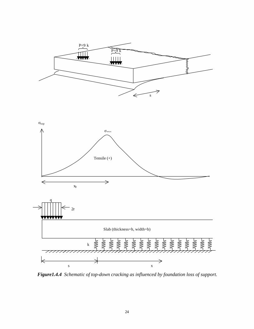
24
Figure1.4.4 Schematic of top-down cracking as influenced by foundation loss of support.
x0
σtop
σmax
Tensile (+)
x
k
2r
q
s
Slab (thickness=h, width=b)
P=9 k P=9 k
s
25
Loss of support comes from any gap or void that may develop over time between the base and the slab, causing increased deflection of the slab surface. Loss of support can have a major impact on pavement performance. Loss of support can have two major components: an intermittent one from daily curling effects, and a permanent one from high temperature construction curling effects and/or long-term effects of pumping erosion and warping. The pumping action occurs when “… a heavy wheel load approaches a joint or crack, the approach slab deflects and forces water trapped under the slab to transport fine material underneath the leave slab. As the wheel load crosses the joint or crack, the sudden vertical pressure on the leave slab causes pumping or ejection of the water and loose material from beneath the slab through the joint or crack. A large part of the fine material that is eroded from beneath the leave slab is deposited under the approach slab.” (Titus-Glover et al., 1999) This action will over time develop faulting at the joint due to the build up of fines under the approach slab. Poblete et al. (1989) found that daily slab curling combined with moisture and heavy vehicle loading appears to be instrumental in developing pumping and warping conditions, which result in permanently upward curved slabs. Field results from Chile and the United States have shown that premature transverse cracking and corner breaks in JPCP may be the result of top down cracking from curling/warping effects and loss of support factors without signs of pumping (Poblete et al. 1989, and Hansen et al., 1998). The interaction between slab curling and intermittent/permanent loss of support needs to be better understood to be able to fully analyze the situation of top-down cracking. In the case of corner loading, higher concrete strength (increased PCC elastic modulus, and tensile strength), stiffer foundations with intermittent and/or permanent loss of slab support all are contributing factors for increased tensile stresses away from the joint. The Role of Concrete Fracture Properties in Transverse Cracking Bache and Vinding (1990/1992) were some of the first researchers to advocate applying concrete fracture properties in the pavement design to enhance long-term pavement performance. There are two main fracture mechanics concepts: (1) is related to the peak failure behavior, and (2), which is more comprehensive, is based on the complete peak- and post-peak fracture behavior. Bache and Vinding suggested using the PCC fracture behavior in terms of peak- and post-peak response to evaluate the development of transverse cracks, and the use of an additional PCC parameter defined as the specific fracture energy. The peak behavior relates to crack initiation, and post-peak behavior relates to crack propagation. Titus-Glover et al. (1999) developed fracture mechanic models for the initiation of bottom-up transverse cracking and top-down corner breaks based on the peak load. The approach of using the peak/failure load information to estimate the onset of cracking is more appropriate in the case where a “catastrophic” failure will occur as in the case of early-age joint development. Soares and Zollinger (1997) developed a methodology to
26
evaluate the saw-cut timing and depth of transverse joints based on the same concept of peak load information. A recent study showed that the coarse aggregate plays a major role in crack initation and propagation in PCC highway mixes (Hansen and Jensen, 2000; and Jensen and Hansen, 2000). Furthermore, it was found that concrete strength cannot alone predict the concrete fracture behavior because the behavior is largely affected by the material characteristics and in particular by the coarse aggregate type, size, and content. Five aggregate sources were investigated and it was found that concrete containing aggregates such as crushed limestone or blast furnace slag had at early ages higher resistance to crack initiation compared to the investigated glacial gravels. However, at any given point in time the concrete containing gravels had higher resistance to crack development than the investigated dolomitic limestones and blast furnace slag. It is important to keep in mind that PCC fracture properties are dominated by the selected coarse aggregates and that the aggregate properties vary between sources. This indicates that the PCC fracture properties should be evaluated for the project specific coarse aggregate. Early-age Factors Early-age transverse cracking is related to the hydration process and the associated temperature rise. During the subsequent cooling process, tensile stresses develop in the slab due to external restraints resulting from friction between the slab and the base, slab weight, tied adjoining lanes, or a combination thereof. Furthermore, increasing joint spacing increases the friction stress. In design, the friction coefficient is typically assumed to be a constant on the order of 1.5 (Huang, 1993). Tensile stresses may also result from shrinkage as the pavement dries out, or expansion as the pavement becomes wet. It is noted that when calculating joint openings due to shrinkage and seasonal thermal changes, it is recommended to use different adjustment factors for a stabilized base or a granular base (see equation 1.4.1). It is assumed that the joint openings are about 25 percent larger for a granular base than for a stabilized base, which indicates that the friction coefficient for a granular base is smaller than for a stabilized base. Joint spacing also affects the curling stresses in that increasing spacing increases the tensile curling stresses. Field investigations made by Frabrizzio and Buch (1999) support this theory. They found that the number of transverse cracks per slab increased from 1.0 crack to 3.7 cracks per slab when the joint spacing increased from 4.9 m to 21.6 m, respectively. Traffic and Environmental Factors Accumulated traffic and environmental loading affect the initiation of transverse cracks through accumulated fatigue damage. The PCC fatigue is assumed to occur when the combined loading exceeds a fatigue threshold. Typically, proper pavement thickness, strength and stiffness requirements minimize the fatigue cracking (Huang, 1993).
27
Accumulated traffic and environmental loading also affect the deterioration of transverse cracks. The repeated loading over time can lead to degradation and crushing of the coarse aggregate, reducing the aggregate interlock. The environmental loading through ambient temperature affects the measured LTE as increasing temperature causes the slab to expand and close the crack, whereas decreasing temperatures cause the crack to open (Foxworthy, 1985). Pavement Age The pavement age is also a factor in deterioration. It serves as an indicator of the amount of cyclic opening and closing of cracks, the number of freeze-thaw cycles, and the degree of corrosion of reinforcement in JRCP’s. The crack deterioration related to cyclic opening and closing of the crack has also been found to be more severe for JRCP’s constructed in colder and wetter climates than for those constructed in warmer climates (Pittman, 1996). Foundation Support Increasing the base and subgrade support has been found to decrease the transverse crack deterioration rate. Colley and Humphrey (1967) found that increasing the modulus of subgrade reaction from 24 to 123 kPa/mm increased the LTE significantly. In particular, the LTE for larger crack widths of 1.5 to 2.0 mm was higher on the stiffer subgrade. Summary In summary, PCC properties are primary factors in the development of transverse cracking in JPCP. The key PCC properties include: flexural strength, elastic modulus, coefficient of thermal expansion, and fracture energy. The PCC resistance to crack development is evaluated through specific fracture energy. (See section 1.5.4 and section 5.5 for details.) 1.5 PCC Properties and Materials Characteristics with Significant Influence on Pavement Performance Considering the findings of the literature review on PCC properties affecting pavement performance, eight key properties were identified. They include PCC compressive strength, flexural/tensile strength, elastic modulus, fracture energy, coefficient of thermal expansion, permeability, air void system, and shrinkage. PCC shrinkage was mainly found to affect JPCP joint opening. However, as the subsequent tasks of this study are based on field studies of JPCP, the irreversible field shrinkage cannot be determined. In addition to these PCC properties it was found in section 1.4 that aggregate characteristics have a major impact on aggregate interlock as related to joint and crack load transfer efficiency. Therefore, mix characteristics affecting joint or crack aggregate interlock are also evaluated in this section.

28
Each of the remaining seven properties was evaluated in the context of increasing design strength (28-day compressive strength from about 24 to 45 MPa) and relations to the other properties and to material characteristics. Table 1.5.1 identifies for each of the key PCC properties (and aggregate interlock), the PCC mix characteristics which have been found to have a significant influence on these properties. The mix characteristics are coarse aggregate characteristics, w/c ratio, cement type and content, mineral additives, and air entrainment. The category for coarse aggregate is fairly broad as it spans from aggregate size, type, gradation, hardness, angularity, soundness to environmental exposure, and reactivity. As stated in section 1.4, it is beyond the scope of this study to evaluate factors such as aggregate soundness and reactivity. Water/cement ratio and coarse aggregate characteristics are the most important PCC mix characteristics from the viewpoint of PCC mechanical properties and in turn JPCP structural performance. Water/cement ratio and air entrainment are the most important mix characteristics when considering PCC and JPCP durability. The following sections briefly discuss each of the properties listed in table 1.5.1.
Table 1.5.1 Primary variables affecting PCC properties.
PCC Property Coarse Aggregate
Characteristics*
w/c ratio
Cement Type and Content
Mineral Additives
Air Entrain.
Compressive Strength X X X X X Flexural/ Split Tensile Strength X X
Elastic Modulus X X Fracture Energy X X
Permeability X X X Coefficient of Thermal Expansion X X
Air Void System X JPCP aggregate interlock X
* Coarse aggregate size, angularity, gradation, content, and type. This section summarizes the detailed literature review performed in the first year of this project. The literature review is reported in “Effect of Higher Strength and Associated Concrete Properties on Pavement Performance,” Interim Report, Federal Highway Administration (FHWA), September 27, 1996. 1.5.1 Flexural and Splitting Tensile Strength The flexure and splitting tensile strength are properties directly related to the performance of PCC pavements. The PCC tensile characteristics directly affect the initiation of transverse cracking and corner breaks. Limited literature exists on the effect on flexure and tensile strength as the compressive strength increases (ACI Committee 363, 1984; and Tachibana et al., 1981). It is believed that the material characteristics, in general, affect the tensile properties in a similar manner as the compressive strength. However, recent literature suggests that factors determining the aggregate-matrix bond are more
29
important to PCC tensile capacity than compressive strength even in the normal strength range (Forster, 1997; Vervuurt, 1997; and Mohamed and Hansen, 1999). Model predictions for the relationship between the tensile strength and the compressive strength indicate the influence of mix design parameters. This is also reflected by the relationship between the compressive strength and the flexure strength (ACI Committee 363, 1984; and Carrasquillo et al., 1990). Furthermore, the flexure strength is not a pure material property, but rather a structural property (Neville, 1983). 1.5.2 Compressive Strength Although compressive failure rarely occurs in the pavement structure, the compressive strength of concrete is perhaps the most comprehensive measure of concrete quality. The compressive strength is directly related to the microstructure of the hardened concrete (Mehta and Aitcin, 1990). Higher strength concrete behaves increasingly as a homogeneous material in pre-peak loading, where the propagation of microcracks does not initiate until just prior to failure. At the same time, the fracture behavior becomes more brittle (Mehta and Monteiro, 1993; and Marzouk and Chen, 1995). The compressive strength is mainly related to the w/c ratio. As the w/c ratio decreases, the compressive strength increases (Mindess and Young, 1981; Neville, 1983; and Mehta and Monteiro, 1986). Furthermore, strength of the coarse aggregate, mineralogical origin, and quality can become controlling factors at high compressive strengths. In addition, aggregate type influences the characteristics of the aggregate-paste bond at the interfacial transition zone (Mehta et al., 1990; Zia et al., 1991; and Zhou et al., 1995). Increasing aggregate size generally decreases the water requirements for the same consistency, and should thereby also benefit the strength of the concrete. At the same time, larger aggregate also increases the possibility of defects within the aggregates. For these reasons, aggregate properties become more crucial for higher strength concrete than for normal strength concrete (Mindess and Young, 1981; and Mehta et al., 1990). Aggregate gradation is important to workability, strength, and durability. In general, the sand content is from 40 to 60 percent of the total aggregate content depending on the aggregate type and maximum aggregate size. For higher strength concrete, with higher cement content, the sand should not be too fine because it will increase water requirements (Cramer et al., 1995). Certain chemical admixtures improve the workability (Aitcin and Lessard, 1994). Entrained air also enhances workability, but decreases the compressive strength (Neville, 1983). Use of entrained air is important from a freeze-thaw durability point of view. Mineral additives such as silica fume and fly ash are commonly used in concrete structures. The mineral additives affect the strength of the concrete. Fly ash is not as effective as cement in increasing early strength, and its effectiveness is dependent on the classification of the fly ash. However, the slow pozzolanic reaction can lead to improved long-term strength. It is recommended that fly ash not exceed approximately 25 to 35 percent of the cementitious material according to American Concrete Institute (ACI)
30
standard 211.4R (1989). Mainly, the use of fly ash reduces the permeability, thermal cracking, and material costs (Tachibana et al., 1990). 1.5.3 Elastic Modulus The PCC elastic modulus is an important variable in pavement design as it controls the overall slab deflection from traffic loading and the slab curling stresses. The elastic modulus increases as the compressive strength increases, and it is found that in general the material characteristics affect the elastic modulus in the same manner as the compressive strength. It should be noted that aggregate type and gradation have strong influence on the elastic modulus (Mehta et al., 1990; and Mehta and Monteiro, 1993). Several relationships between elastic modulus and the compressive strength are presented in the literature (Neville, 1983; Mehta and Monteiro, 1993; Mindess and Young, 1981; and Ahmad, 1994). Use of such a relation has to agree with the conditions under which the original data are obtained. In general, the use of such a relationship for normal strength concrete will not be applicable for higher strength concrete. 1.5.4 Fracture Energy Concrete strength cannot alone predict the concrete fracture behavior because the behavior is largely affected by the material characteristics and in particular by the coarse aggregate type, size, and content. A number of studies have been performed evaluating the effect of coarse aggregate properties on the concrete fracture properties (e.g. Petersson, 1981; Kleinschrodt and Winkler, 1986; de Larrard and Malier, 1992; Kan and Swartz, 1995; Zhou et al., 1995; and Giaccio and Zerbino, 1998). It is important to keep in mind that the framework for these studies was traditional structural concrete and not paving concrete. The concrete fracture energy is given by a combination of the fracture energy of the matrix and the coarse aggregate. For normal strength concrete, the coarse aggregates form the most significant component with a contribution of approximately 85 percent. In other words, the aggregate interlock (bridging and frictional effects) has a significant effect (de Larrard and Malier, 1992; and Bache and Vinding, 1990/1992). The coarse aggregate is found to be the most important factor for fracture energy. Petersson (1981) reported that the difference in fracture energies lie in the effective crack path. For strong aggregates the crack runs around the aggregate, whereas for weak aggregates the crack penetrates and fractures the aggregates. The crack path also depends on the paste-aggregate bond. Increasing the aggregate size improves the fracture properties. Studies reported by Petersson (1981), Kleinschrodt and Winkler (1986), and Karihaloo (1995) showed that increasing the coarse aggregate size increases the fracture energy. Karihaloo states that the increased fracture energy is due to the effect of aggregates as “crack obstacles.” The
31
crack has to change directions to pass around the aggregates, and this requires additional energy compared to that required for a straight- line crack. It was found that only the post-peak response is affected and that increasing aggregate size allows more energy to be absorbed by the concrete. It has been suggested that a higher volume concentration of particles (aggregates) which are stronger and stiffer than the matrix would also increase the fracture energy (Monterio and Helene, 1994; and Bache and Vind ing, 1992). Petersson (1981) did a limited study with cement to aggregate ratio from 0.4, 0.5, and 0.6. He found that the fracture energy did increase with increasing aggregate fraction, but the elastic modulus was more affected. It is important to keep in mind that the framework for these studies was traditional structural concrete and not paving concrete. Karihaloo (1995) illustrated that aggregate textures affect the fracture energy. However, in contrast to aggregate type, size, and content, the aggregate shape and angularity tend to affect the peak area more than the tail area. Crushed materials tend to reach higher peak stress than rounded materials. In general, the effect of aggregate shape and angularity has less impact on fracture energy than the aggregate type and size. In general, the load-deflection response for high strength concrete is different from the response of normal strength concrete. The pre-peak response shows that the higher strength concrete generally has a higher load carrying capacity and stiffness than normal strength concrete, and the post-peak response shows that the descending branch is steeper for higher strength concrete than for normal strength concrete. Overall, the total area under the load-deflection curve is larger for higher than for normal strength concrete but the overall response of higher strength concrete is more brittle than the response for normal strength concrete, (Marzouk and Chen, 1995). The fracture energy value increases as w/c ratio decreases and the area under the load-deflection curve increases (Petersson, 1981; and Kan and Swartz, 1995). 1.5.5 Permeability Although there is no single standard test for assessing the durability of concrete exposed to different conditions, permeability is generally considered the best parameter for characterizing the ability of concrete to resist deterioration (Schonlin and Hilsdorf, 1988). The permeability of concrete is a measure of the ability of various fluids to be transported through concrete’s porous microstructure. Permeability can be an indicator of long-term performance, especially when considered in conjunction with other concrete properties (Armaghani et al., 1992). The literature has shown that permeability is strongly related to w/c ratio, chemical admixtures, mineral additives, and aggregate properties (e.g. Mobasher and Mitchell, 1988; Schonlin and Hilsdorf, 1988; Mehta, 1990; Kosmatka and Panarese, 1992; and Ollivier et al., 1995). It is widely accepted that lower w/c ratio decreases permeability. Furthermore, replacing cement with ground granulated blast furnace slag and fly ash also
32
decreases permeability, but these additives can be sensitive to curing conditions. Aggregate type and size have also been shown to affect the microstructure enough to affect permeability results, although individual testing of sources is recommended. 1.5.6 Air Content and Freeze-Thaw Durability The freeze-thaw durability of the paste is controlled by the air void system of the concrete. Factors affecting the freeze-thaw durability of the concrete are the paste pore system, entrained air, and freeze-thaw resistant aggregates. D-cracking is a freeze-thaw problem directly related to the coarse aggregate, characterized by the aggregate internal pore structure and maximum aggregate size. The durability of aggregate is not covered in this study, as it is already well explained in the literature. The freeze-thaw durability of normal strength concrete can be estimated from the spacing factor, which indicates the distribution of air voids in the paste (a spacing factor less than 0.2 mm is required for freeze-thaw resistance) (Powers, 1945 and 1949). For higher strength concrete the requirement is not clear, but ACI allows a one-percent reduction in recommended air content for 28-day compressive strength higher than 34.5 MPa. It is not fully understood how the air content affects the freeze-thaw durability for higher strength concrete (ACI 318, 1995). The air system in the hardened concrete is highly related to the concrete mix and the finishing procedures. For example, decreased w/c ratio, finer ground cement, finely divided mineral additives and high proportion of fines in the fine aggregate all lead to less entrained air (Mindess and Young, 1981). Using air-entraining admixtures with proper mixing, placement and finishing can provide a well-distributed air system. It is found that entrained air reduces bleeding and segregation of the fresh concrete, which minimizes the system of microcracks in the hardened concrete. The disadvantage of entrained air is the associated decrease in compressive strength. 1.5.7 Coefficient of Thermal Expansion The value of the coefficient of thermal expansion (CTE) is considered very important for joint movement and slab curling (PCA, 1988). The literature review has shown that CTE is highly dependent on the mix composition (Neville, 1975; Addis, 1986; and Van Dam, 1995). The CTE of concrete is determined by the CTE of cement paste and aggregate. Aggregate type has the highest influence on the value of thermal expansion due to the high volume content of coarse and fine aggregate in concrete (Zoldners, 1971). While moisture conditions have significant influence on the thermal properties of the cement paste, the effect is greatly reduced for concrete as a whole (Meyers, 1950). This is thought to be the case for both normal and higher strength concrete. The methods for measuring CTE of concrete have not been standardized by the American Society for Testing and Materials (ASTM) or AASHTO, although AASHTO recently adapted the FHWA method as provisional standard TP-60-00. In recent years, several methods have been developed for research purposes (Emborg, 1989, and Bjontegaard,
33
1999). These methods are sometimes specially designed for measuring CTE of early age concrete. Test results from Emborg and Bjontegaard indicate that CTE decreases rapidly with age and becomes almost constant after 28 days. The method used in this research project is not specially designed for early age concrete but allows a relatively quick determination of CTE so that other forms of deformation (autogeneous shrinkage and swelling) can be minimized. 1.5.8 Coarse Aggregate Characteristics Affecting Joint/Crack LTE Sutherland and Cashell (1945) found that concretes made with rounded gravel had better load transfer characteristics than concretes made with similarly graded crushed limestone. The difference was attributed to the concrete crack face. It was observed that the concrete containing gravel generated a rough surface and the concretes with limestone generated a smoother surface, due to cracking around instead of through the aggregate. Abdel-Maksoud et al. (1998) evaluated the effect of coarse aggregate type on laboratory specimens subjected to cyclic shear. They found that for a low number of cyclic loadings the responses for limestone, gravel and trap rock were comparable. However, under an increasing number of cycles, the limestone exhibited a rapid increase in displacement compared to the gravel and the trap rock. The difference in behavior was explained by the varying degrees of resistance to degradation and crushing. The authors of the study showed that aggregate properties like Los Angeles abrasion and Crushing Value correlated with these observations. These findings are also in agreement with results reported by Sutherland and Cashell (1945). In addition to coarse aggregate type, coarse aggregate angularity also affects the load transfer characteristics. Colley and Humphrey (1967) showed that the load transfer characteristics improved significantly from the behavior of a natural gravel to a crushed natural gravel. Sutherland and Cashell (1945) and Nowlen (1968) studied the effect of coarse aggregate size, and found that by increasing the aggregate size, from a nominal maximum aggregate size of 38 to 62 mm, the load transfer was increased. Abdel-Maksoud et al. (1998) also reported that increasing the nominal maximum aggregate size from 25 to 38 mm decreased the displacement needed to mobilize a given shear stress. Results from gravel and trap rock indicated the same trends. Furthermore, the study also indicated the importance of coarse aggregate size in relation to crack width. They suggested that coarse aggregate size to crack width ratio is a likely controlling parameter for aggregate interlock.
35
CHAPTER 2. RESEARCH METHODOLOGY FOR DETAILED FIELD AND LABORATORY EVALUATION
The intent of this project is to evaluate the effects of PCC properties and materials characteristics on pavement performance in the context of increasing strength. This chapter focuses on the selection of pavement test sections and the field and laboratory techniques used in their evaluation. Chapter 3 discusses the selected sites and the variables covered. Due to the limited number of JPCP field sites with PCC of higher strength, it is important that the literature review and succeeding field and laboratory studies are covering as wide a range as possible in the PCC strength and associated properties. Data must be obtained to determine the required levels of the PCC strength and associated properties, which are associated with good long-term performance of the JPCP’s. Based on analysis of these data, recommendations can be made for the required levels of PCC properties and mix characteristics necessary for good long-term JPCP performance. Furthermore, because a wide range in PCC strength has been evaluated it is possible for engineers to interpolate and extrapolate within the project database aided by theory and pavement models. This objective was met by evaluating the FHWA Long Term Pavement Performance (LTPP) database. Based on this preliminary investigation overall PCC and performance trends were established. The following section discusses the observations made from this analysis. Test section selection has been done primarily using the SHRP LTPP database. Selection criteria are based on concrete strength, geographic location, age, design features, loading history, and performance characteristics. A major goal in test site selection was to identify good and poor performers within each climate type for comparison. Variation of parameters which do not play highly significant roles in performance were minimized, allowing the effects of critical parameters to be better quantified. Field site surveys were designed to accurately evaluate the current pavement condition of each site, and to specifically identify and quantify distresses and unusual features. Field surveys include distress mapping, site photos, falling weight deflectometer measurements, dynamic cone penetrometer measurements, dipstick surface profile measurements, drainage surveys, general site surveys, concrete sampling and soil sampling. Laboratory analyses of concrete samples from these test pavements focus on determining their key physical properties and material characteristics. These laboratory tests include concrete strength (compressive and splitting tensile), elastic modulus, transport properties (water and air permeability, rapid chloride permeability test, and water absorptivity), coefficient of thermal expansion, petrographic analysis of distress, air void analysis, aggregate type, size and gradation, cement content, and w/c ratio determination.
36
2.1 Information on Pavement Performance, PCC Properties, and Material Characteristics Obtained from the SHRP LTPP Database As was observed in the literature review, the number of variables that affect concrete pavement performance are numerous, and no one or two variables appear to have a dominant impact for any distress mode. The fact that so many interacting variables affect performance of the pavement system would dictate that a large number of test sites covering the full range of each parameter be selected to fully examine the statistical impact each variable has on observed pavement performance. Current studies such as the LTPP Program are investing the resources required to obtain enough data to conduct meaningful statistical analysis of the factors affecting pavement performance. The project team has used the SHRP-LTPP data to examine the impact of each of the critical variables. 2.1.1 Overview of the LTPP Database The LTPP program was initiated in 1987 and is designed to be a 20-year program. The first 5 years of the program were conducted under the SHRP, and it then was transferred to the FHWA. As stated on the cover of the latest version of the LTPP database, DataPave 97, the LTPP program is expected to be the largest available pavement performance database, with enormous potential for the development of products to improve pavement technology. The pavement sections in this database are located in all States of the United States and in Canada. In this study pavement sections under the General Pavement Studies (GPS) have been included for investigation. The GPS sections were in service at the time of selection, either in their original design phase or their overlay phase. Furthermore, only the plain jointed pavement sections, identified as GPS-3, have been included for evaluation. The LTPP Information Management System (IMS) data used for identifying the ranges of concrete properties was requested in October 1995. It is important to emphasize that the database was not complete at that time. A newer version, DataPave, is now available.
2.1.2 Available Information in the LTPP Database To date, considerable amounts of data have been collected on pavement construction, maintenance, rehabilitation, and performance. The data is stored in the LTPP database, which maintains information on different pavement types. The types of data that may be available for each section include an inventory of design and construction parameters, environmental factors, results of material testing, pavement monitoring parameters (e.g. deflection and distress), traffic, maintenance, and rehabilitation activities. The environmental data contain a wide variety of information, including both monthly and annual summaries of climatic parameters such as: freezing index values; number of freeze-thaw cycles; maximum, and average air temperatures; precipitation; relative
37
humidity; and wind speed. In addition, detailed location information is provided for each recorded weather station. Environmental information provides a basis for understanding how climate has impacted pavement performance. Such parameters as climatic zone, number of freeze-thaw cycles, and freezing index have been closely related to pavement performance. Other environmental factors, such as maximum and minimum temperatures, are also thought to play an important role. This information was initially used to evaluate climate effects on performance and to select candidate pavement projects over a variety of climatic conditions for the field investigations in this study. The inventory information contained in the LTPP database can be divided into two general categories: descriptive/design information, and construction/materials information. Descriptive/design information includes section location and layout, layer thickness, age, joint spacing, percent steel, load transfer type, shoulder configuration, lane width, subdrainage, etc. These types of data are very useful in identifying design features, which may impact pavement behavior. Construction/materials information includes PCC mix design parameters, aggregate type and gradation, and PCC strength and stiffness values obtained during construction. Under the LTPP Program, each experimental site is being monitored to provide a systematic assessment of the pavement condition. Monitoring activities include nondestructive testing using a falling weight deflectometer (FWD), longitudinal profiling, identification of surface distress, frictional measurements, and transverse profiling. These regularly scheduled monitoring activities are conducted using well-documented techniques and calibrated equipment. Pavement performance, as measured by changes in pavement condition as a function of time, traffic, and climate, can thus be assessed. Of significant interest to this study are the surface distress data. These data have been collected both manually and through automated means. Manual surveys are conducted in accordance to standardized procedures from SHRP-P-338 (1993). The distresses in this category are cracking, joint deficiencies, surface defects, and miscellaneous distress. Furthermore, the database contains information on joint and crack faulting. The traffic information was in part generated from estimates and collected on site using weigh in motion (WIM) technology. Considering these data, information can be obtained on growth rate for Equivalent Single Axle Loads (ESAL’s), cumulative ESAL’s, initial ESAL rate and average ESAL’s. Under the LTPP program, an extensive amount of field drilling, sampling, and material testing has been and continues to be performed. Data has been collected on all the pavement layers including the PCC base, subbase, and subgrade. The information on PCC material properties includes compressive strength, splitting tensile strength, and static elastic modulus. At this point in time no information is available on hardened concrete permeability, air content or flexural strength. The amount of data available under the material testing section is highly variable, and some sections have only limited information. However, the material testing data are instrumental in test site selection.
38
2.2 Selection of Candidate Pavement Sections 2.2.1 Introduction It was the task of the project investigators to establish a pavement selection criteria philosophy based on the results of the information search and the limits of the project budget, which maximizes the usefulness of the field study. The following methodology was used during site selection. First jointed plain concrete pavements from the LTPP GPS-3 database were selected based on climate, age, strength, traffic, and distress levels. A few test sites outside the LTPP database were also selected based on recommendations from SHA officials. Then, scatter plots of key parameters were generated and reviewed to determine if any of the selected projects were nonstandard or outliers from typical pavement sections or foundation types. This process was repeated until a set of sections was established which had good balance between distress levels, PCC properties (with emphasis on strength), and mix parameters. The following discussion considers some of the more critical factors that influence pavement performance, and describes how each was addressed in the selection of proposed candidate pavement sections. 2.2.2 Climate Climate is indisputably a major factor that contributes to the performance of PCC pavements. Temperature and moisture fluctuations lead to expansion and contraction of the PCC and cyclical upward and downward curling or warping of the slab ends results in ever changing stress patterns and the relative movement at joints and cracks. These effects, combined with load induced stress, strongly control the rate of deterioration of the pavement system. Many PCC pavement distresses can occur only under the influence of both temperature and moisture extremes. For example, frost heave not only requires below freezing temperatures, it also needs a ready supply of moisture. Furthermore, a distress such as spalling due to aggregate freeze thaw damage can only occur if the poor quality aggregate is in near saturated condition as it freezes. The classification approach adopted by this study is to define four major climatic regions as follows (Rauhut et al., 1984; and TRB, 1986): • Wet-Freeze (WF). • Dry-No-Freeze (DNF). • Dry-Freeze (DF). • Wet-No-Freeze (WNF).
39
2.2.3 Concrete Strength It has proven difficult to define what constitutes “higher than normal” concrete strength for pavements. In addition, the age at which the concrete is tested also has significant impact on the observed strength. Concrete strength data obtained through testing of cores were available in the LTPP data. It was also observed in the literature that compressive strength is commonly used to distinguish higher strength from normal strength concrete. Thus it was decided to use inservice compressive strength, as obtained from testing of cores of existing pavements as the primary strength parameter in the selection process. The use of compressive strengths obtained from cores has at least one added advantage. Because the sections selected for evaluation are at least 10 years old, little additional strength gain would be expected. Thus, the compressive strengths obtained could be considered as near ultimate concrete compressive strength. This is an important concept, as there are concerns being voiced in the industry that over time cements have evolved towards higher earlier strength gain with lower additional strength gain after 90 days resulting in lower ultimate strengths. After examination of relevant literature, a study of the LTPP data, and discussion among the Technical Advisory Panel (TAP), an insitu concrete compressive strength of 48 MPa (7,000 lbf/in2) was selected as a reasonable estimate of the average long term inservice strength of PCC pavement. The strength philosophy used for the selection process was to have eight to nine sections of higher than average strength and three to four sections of lower than average strength. Furthermore, the selections were made to obtain a range of performance/distress levels within the different climates. 2.2.4 Distress Pavement performance, as defined by the initiation and progression of distress over time, is the overriding concern of every pavement designer. Distress level was therefore one of the most important factors used to select pavement sections for further evaluation in this study. As mentioned earlier, the observation of superior performing pavements in the State of Washington was a catalyst for the creation of this study. It was noted that many of these pavement sections had insitu concrete compressive strengths well in excess of that normally encountered, some exceeding 69 MPa (10,000 lbf/in2). The literature review has indicated that strength may have played a secondary role in performance in the State of Washington. In the case of the Seattle concrete several parameters may have played significant roles in the performance characteristics observed. These include the combination of a thermally stable climate (very little hot or freezing conditions), a moist climate (modest annual precipitation but high number of wet days per year), and good quality aggregate in the foundation layers and in the PCC.
40
Distress types considered in the selection process include transverse joint spalling, transverse slab cracking, transverse crack deterioration, and faulting. It is noted that sections identified as having durability related cracking were eliminated from consideration, as agreed to during the first meeting with the TAP. 2.2.5 Pavement Age It was imperative that the selected pavement sections had a sufficient age so that deterioration from climatic and load factors had occured. For about the first 10 years of service, typical well constructed concrete pavements have little observable damage. After this time, superior performing pavements begin to distinguish themselves with far fewer observances of pavement distress. At ages in excess of 20 years, only exceptional pavements are expected to have little or no observable distress. Thus, pavement sections considered for further analysis in this study were grouped into one of two age categories. The younger sections are between 10 and 20 years old, while the older sections are 20 years or older. 2.2.6 Traffic All pavement design methods consider traffic loading as an important design variable. Traffic is largely responsible for the rate of development of numerous pavement distresses. Highway traffic consists of a diverse mix of vehicles, each having unique loading characteristics. Researchers who analyzed data collected at the American Association of State Highway and Transportation Officials (AASHTO) road test developed equivalency factors that relate damage induced by various load and axle configurations (as measured by the change in pavement serviceability) to that of a standard 80-kN (18,000-lb) single axle load for various pavement structural sections (AASHTO, 1993). Through the use of these equivalency factors, a diverse mix of traffic can be “converted” to a single metric referred to as equivalent single axle loads (ESAL’s). The term ESAL’s is the most common traffic index used in the design process and is calculated and reported by most SHA’s. It is also one measure of traffic provided in the LTPP data. Because ESAL’s are commonly understood and reported, the ESAL was chosen as the traffic variable in the selection of experimental pavement sections. Each pavement section examined in this study has a different age, making it impractical to use cumulative ESAL’s as a selection criterion. Instead, ESAL rate was used; as defined by the total cumulative ESAL’s divided by the age in years. Although there is no universally accepted value separating low from medium or high traffic, a rate of 300,000 ESAL’s per year was considered appropriate. This is based on the distribution of ESAL rates observed in the LTPP data and the assumption that 6 million ESAL’s within a 20 year design life is a good demarcation between a secondary and primary route. 2.2.7 Joint Spacing and Reinforcement The national trend in PCC pavement design is toward short-jointed, plain, doweled concrete pavements. According the web site of the American Concrete Pavement
41
Association (ACPA), the majority of States are now building primarily jointed plain concrete pavements (JPCP). Only 9 States currently construct jointed reinforced concrete pavements (JRCP) sections, and 8 construct continuous reinforced concrete pavements (CRCP). Typical slab lengths have also become shorter, with many states using 4.5-m (15-ft) or shorter slabs. Only one State builds JPCP sections with slab lengths greater than 6 m (20 ft). The literature review and analyses of the LTPP pavement performance data has indicated that pavements with long slab lengths are more sensitive to climate and foundation conditions than shorter sections. It was therefore decided to maximize the applicability of this PCC properties and materials characteristics study by focusing on the analysis of short (~3.6 to 6 m (~12 to 20 ft)) slab JPCP where joint movements are minimized and mixture characteristics play a more significant role in long-term performance. Maximum joint spacing for JPCP is typically less than 6 m (20 ft) and in many instances less than 4.5 m (15 ft) which is well below the critical slab length where maximum curling/warping related bending stress and joint deflection occurs. 2.2.8 Other Design Parameters There are many other variables that impact concrete pavement performance. These include pavement thickness, base type, subgrade type, drainage conditions, shoulder type, joint sealant, load transfer design, and a multitude of others. Due to the rigorous nature of the proposed testing regime, relatively few sections will be investigated. It was thus attempted to hold other variables within a reasonable range when selecting sections for study.
2.3 Details of Field Evaluation of Selected Pavement Sections 2.3.1 Introduction The field evaluation portion of this study was conducted to provide valuable information concerning the field conditions of the candidate pavement sections and to supply concrete samples for use in the subsequent laboratory analyses. This evaluation consisted of continued background information collection, onsite visual surveys, core sampling, and evaluation of existing nondestructive deflection testing data. 2.3.2 Background Information As discussed previously, the majority of the candidate pavement sections selected for study are included in the LTPP database. Therefore, large amounts of information concerning climatic conditions, design, construction, traffic, and maintenance activities are available. These sections have also been monitored and tested for distress, structural response, and strength parameters.
42
Some of this data was compiled during the site selection process but more was available. The project team utilized that LTPP data in greater detail later, examining materials and construction factors. Structural response data from nondestructive deflection testing was also sought. Specifically, the following types of information were sought, documented, and analyzed:
• Design Information - slab dimensions (thickness, length, and width), load transfer method, type of shoulder, support characteristics (base, subbase, and subgrade), and drainage.
• Material Information - cement type, coarse and fine aggregate types, proportions and gradations, type and quantity of admixtures, and other PCC mixture characteristics.
• Monitoring Information - updated distress, faulting, and nondestructive deflection testing.
• Traffic Information – Annual Average Daily Traffic (AADT), percent trucks, and ESAL’s.
2.3.3 General Site Visit A general site visit was conducted to provide final verification of the suitability of each site for this study through establishing the section’s uniformity of construction, drainage, traffic, and performance. It was also important that the 152-m (500-ft) test section was representative of the pavement project as a whole. The LTPP program invested considerable efforts to verify both uniformity within the section and to ensure that the test section was representative of the project. Specifically, the following criteria established in a previous FHWA study were used (FHWA, 1995):
• Horizontal curves less than three degrees and vertical grades less than 4 percent.
• A minimum of cut/fill transitions, either longitudinally or transversely.
• No culverts, pipes, or other substructures within the section (if possible).
• Uniform traffic flow through the project.
• Identification of any other factors that may in any way compromise the safety of the field survey team such as confined space due to barrier walls or guardrail.
The final purpose of the general site visit was to coordinate with the cooperating SHA in scheduling visual distress surveys and field sampling. 2.3.4 Visual Survey After the general site survey was performed, a detailed visual distress survey was conducted by Soil and Materials Engineers, Inc. (SME) using slight modifications to the procedures outlined in the SHRP Distress Identification Manual for the Long-Term
43
Pavement Performance Studies (SHRP-P-338, 1993). Copies of the forms used during the distress inspections are shown in figures 2.3.1 and 2.3.2. These procedures are very rigorous, recording all visible distress including cracking, spalling, scaling, durability related distress, faulting, and lane-shoulder separation and/or drop off. Joint widths are measured and sealant quality recorded. Other pavement features, including patches, core holes, culverts, bridges, etc., are also noted on the form. Joint faulting is measured using the Georgia faultmeter similar to SHRP procedures (SHRP-P-338, 1993). For this study, spalling and faulting are quantified in greater detail than outlined in the SHRP standard procedures. For spalls, the approximate dimensions of the spall are noted directly on the crack maps for each occurrence. Faulting is measured and recorded to the finest resolution possible by the equipment being used (preferably 0.1 to 0.2 mm (0.0039 to 0.0078 in)). Every discontinuity (crack or joint) is recorded for faulting (zero’s included). In addition, all crack widths are measured and noted on the crack maps during the faulting surveys. Profile/roughness measurements, typically conducted with dipstick type devices, are replaced with dipstick measurements which can measure slab warping and/or construction related curling. In conjunction with the visual distress survey, a drainage survey was also conducted. Ditches were evaluated for standing water, and the presence of vegetation found in swampy areas was recorded. Drainage structures, such as outlets and culverts, were examined and functionality assessed, and pavement and shoulder cross slopes were measured. The drainage field survey form, adapted from a recent FHWA study (FHWA, 1995), is shown in figure 2.3.3. Site location maps detailing all observations were prepared. The nearest milepost was located, as were all fixed structures including culverts, bridges, and highway exits. All coring locations were also shown.

44
Figure 2.3.1 General field survey form.

45
Fig
ure
2.3.
2 D
istr
ess
field
sur
vey
form
.

46
Figure 2.3.3 Drainage survey form.
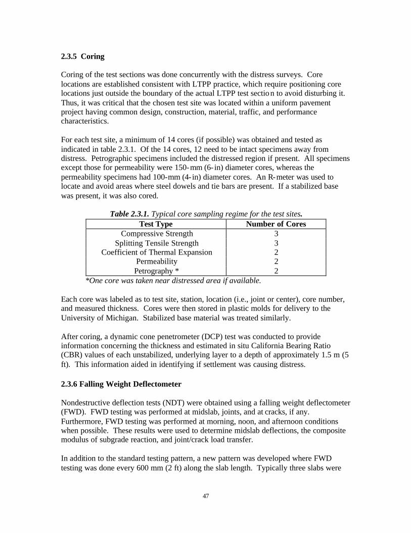
47
2.3.5 Coring Coring of the test sections was done concurrently with the distress surveys. Core locations are established consistent with LTPP practice, which require positioning core locations just outside the boundary of the actual LTPP test section to avoid disturbing it. Thus, it was critical that the chosen test site was located within a uniform pavement project having common design, construction, material, traffic, and performance characteristics. For each test site, a minimum of 14 cores (if possible) was obtained and tested as indicated in table 2.3.1. Of the 14 cores, 12 need to be intact specimens away from distress. Petrographic specimens included the distressed region if present. All specimens except those for permeability were 150-mm (6- in) diameter cores, whereas the permeability specimens had 100-mm (4- in) diameter cores. An R-meter was used to locate and avoid areas where steel dowels and tie bars are present. If a stabilized base was present, it was also cored.
Table 2.3.1. Typical core sampling regime for the test sites. Test Type Number of Cores
Compressive Strength 3 Splitting Tensile Strength 3
Coefficient of Thermal Expansion 2 Permeability 2 Petrography * 2
*One core was taken near distressed area if available. Each core was labeled as to test site, station, location (i.e., joint or center), core number, and measured thickness. Cores were then stored in plastic molds for delivery to the University of Michigan. Stabilized base material was treated similarly. After coring, a dynamic cone penetrometer (DCP) test was conducted to provide information concerning the thickness and estimated in situ California Bearing Ratio (CBR) values of each unstabilized, underlying layer to a depth of approximately 1.5 m (5 ft). This information aided in identifying if settlement was causing distress.
2.3.6 Falling Weight Deflectometer Nondestructive deflection tests (NDT) were obtained using a falling weight deflectometer (FWD). FWD testing was performed at midslab, joints, and at cracks, if any. Furthermore, FWD testing was performed at morning, noon, and afternoon conditions when possible. These results were used to determine midslab deflections, the composite modulus of subgrade reaction, and joint/crack load transfer. In addition to the standard testing pattern, a new pattern was developed where FWD testing was done every 600 mm (2 ft) along the slab length. Typically three slabs were
48
tested. Using these data, the effect of intermittent and permanent loss of support and joint load transfer can be assessed. 2.3.7 Dipstick Profilometer Data In situ slab surface profiles were, when possible, obtained for three or more slabs per test section. Using a Dipstick device, the surface profiles were obtained in the direction of traffic for the outer and the inner wheel-paths along with the slab diagonal. The profiles on the investigated slab(s) were measured in increments of 300 mm (1 ft). A zero beginning elevation was selected at the start point. If the entire test section was measured the site design slopes were removed in order to show small changes in elevation profiles. Furthermore, when possible surface profiles were obtained at morning, noon, and afternoon conditions. The surface profiles can assess slab permanent shape and temperature curling, joint faulting, and slab rotation. 2.4 Details of Laboratory Evaluation of Selected Pavement Sections To quantify and verify the observed trends and levels of concrete properties and material characteristics that produce excellent long-term distress free pavement performance, a field sampling and evaluation program for 15 inservice pavements was conducted. The following properties and material characteristics were necessary for detailed study from the field cores. Physical Properties • Compressive strength (also measured by SHRP-LTPP). • Splitting tensile strength (also measured by SHRP-LTPP). • Elastic modulus (also measured by SHRP-LTPP). • Fracture energy (not measured by SHRP-LTPP). • Permeability (not measured by SHRP-LTPP). • Coefficient of thermal expansion (not complete in SHRP-LTPP). Material characteristics • W/C ratio. • Cement content. • Coarse aggregate gradation. • Percent coarse aggregate. • Coarse aggregate type. • Coarse aggregate maximum size. • Air void content. • Air void size distribution. • Air void spacing.

49
These above parameters offer a mix of primary factors and secondary factors which are used to infer critical parameters such as freeze-thaw durability, brittleness, and primary causes of distress. The methodologies of the laboratory analyses are discussed below. Standardized methods are not discussed in detail. 2.4.1 Methods to Determine Compressive Strength, Splitting Tensile Strength, and Elastic Modulus The PCC properties compressive strength, splitting tensile strength, and elastic modulus are determined according to the following standards: • Compression Testing: Testing guidelines provided in ASTM C 39-94, "Standard Test
Method for Compressive Strength of Cylindrical Concrete Specimens.” • Split Tensile Testing: Testing according to ASTM C 496-90, "Standard Test Method
for Splitting Tensile Strength of Cylindrical Concrete Specimens." • Static Elastic Modulus: Testing according to ASTM C 469-94, "Standard Test
Method for Static Modulus of Elasticity and Poisson's Ratio of Concrete in Compression."
2.4.2 Method to Determine Fracture Energy The PCC fracture energy is proposed as a method to quantify the quality of the coarse aggregate in the concrete. At the same time, the overall PCC fracture behavior can be qualified, as discussed in chapter 7. Fracture energy can be determined from the complete load-deflection response of a notched beam subjected to center-point bending. The RILEM Technical Committee 50-FMC on Fracture Mechanics of Concrete – Test Methods proposed this test method (RILEM, 1985). The procedure is described by several textbooks (Karihaloo, 1995; and Shah et al., 1995). Many researchers have evaluated the test method and it has been found that the beam fracture energy is size dependent. The reason for the size-effect is mainly that the specimen and the loading configuration limit the crack length. However, results can be directly compared when the fracture energy is determined on the same specimen size. Test Specimen The recommended specimen size depends on the concrete maximum aggregate size. The notch depth should be equal to half the beam depth ±5 mm, while the notch width at the tip should be less than 10 mm. Further, it is recommended that the notch is saw-cut under wet conditions. Table 2.4.1 lists the recommended sizes for measuring fracture energy. Depth and width dimensions are the most critical dimensions depending on the maximum aggregate size. The ratio between span and depth, S/D, is recommended to range from 4 to 8 (Karihaloo, 1995). For 25-mm maximum aggregate size, this would require a minimum span of 800 mm and a maximum span of 1600 mm.

50
Table 2.4.1 Recommended sizes of beams for measuring fracture energy. Nom. Maximum Aggregate Size
(mm)
Depth
(mm)
Width
(mm)
Length
(mm)
Span
(mm) 16.1-32 200±5 mm 100±5 mm 1190±10 mm 1130±5 mm 32.1-48 300±5 mm 150±5 mm 1450±10 mm 1385±5 mm
This study
25-38 200±5 mm 100±5 mm 1190±10 mm 965±5 mm
During casting, the beams are mechanically vibrated to avoid entrapped air. The beams cure for at least 24 hours before demolding. The beams cure at ambient room temperature of 20 ± 2 °C at 100-percent relative humidity (RH). Furthermore, the beams remain at 100-percent RH until time of testing/sawing. The notch is sawn on a table-saw with a diamond blade. If a table-saw is not available, a hand-held saw can be used with extreme care.
Test Procedure The beam is tested as a statically determinate beam under constant deformation rate. In the literature it has been recommended that the peak load is reached within 60 seconds from start of test. However, the deformation rate may have to be lower depending on how brittle the material behavior is. The loading rate in this study was such that the peak was typically reached after 4-5 minutes depending on the level of nonlinear deformation before peak. The deformation rate can be controlled either directly from the beam deflection or from the crack mouth opening displacement (or a combination thereof.) Using the crack mouth opening displacement (measured by a clip-gage) induces the most stable test and in particular the peak area is well captured. It is recommended that the beam deflection is measured to the accuracy of at least 0.01 mm, and the load is measured to the accuracy of 2 percent of peak load. Possible nonelastic deformation at the loading and support points is excluded from the beam deflection. A closed- loop servo hydraulic testing machine test is needed to perform a test in displacement control. If such equipment is not available, the stiffness of the testing machine should be larger than that of the steepest slope on the descending part of the curve. It should be emphasized that the descending part (softening) is very difficult to obtain using this method and expert literature should be reviewed. Test Results and Calculations The method to calculate fracture energy depends on the direction of loading. In this case it is assumed that the beam is downward loaded, and therefore the contribution from the beam self-weight and any equipment resting on the beam must be added to the load-deflection curve. The additional load is transformed into an equivalent single point load acting at the center and is added to the measured load. At the same time the associated deflection from the self-weight and any equipment on the beam is estimated using the initial slope of the measured load-deflection curve.
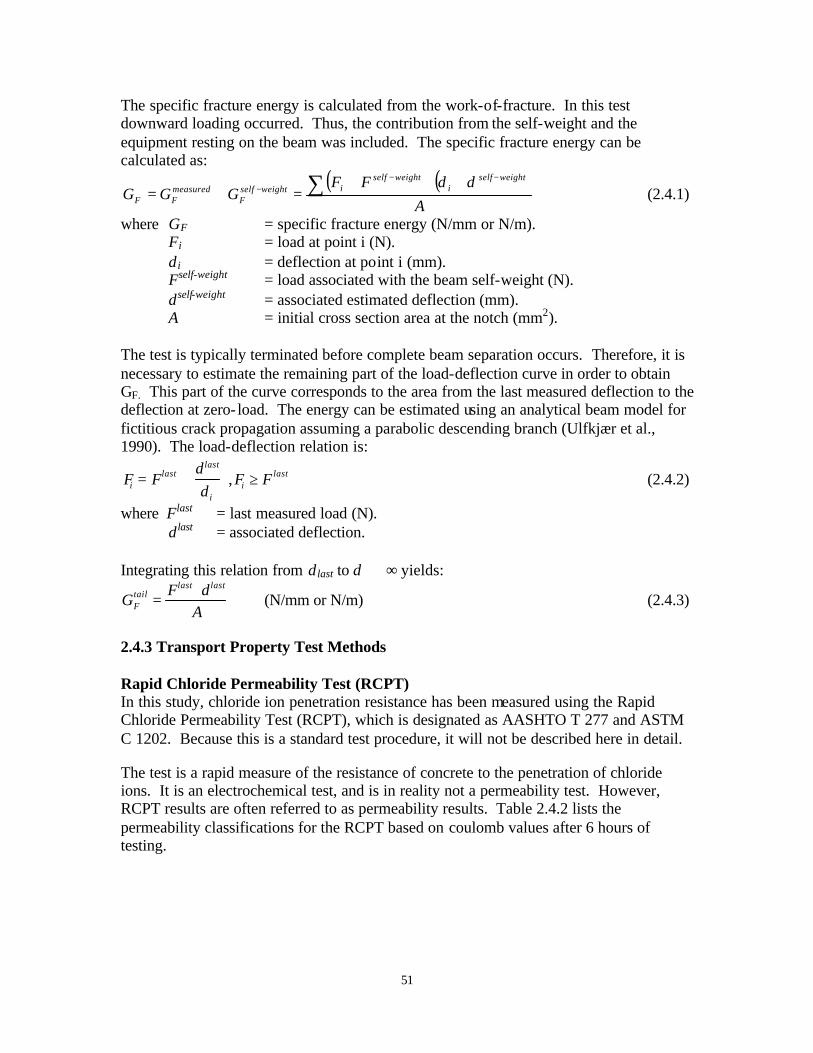
51
The specific fracture energy is calculated from the work-of-fracture. In this test downward loading occurred. Thus, the contribution from the self-weight and the equipment resting on the beam was included. The specific fracture energy can be calculated as:
( ) ( )A
FFGGG
weightselfi
weightselfiweightself
FmeasuredFF
∑ −−− +⋅+
=+=δδ
(2.4.1)
where GF = specific fracture energy (N/mm or N/m). Fi = load at point i (N). δ i = deflection at point i (mm). Fself-weight = load associated with the beam self-weight (N). δself-weight = associated estimated deflection (mm). A = initial cross section area at the notch (mm2).
The test is typically terminated before complete beam separation occurs. Therefore, it is necessary to estimate the remaining part of the load-deflection curve in order to obtain GF. This part of the curve corresponds to the area from the last measured deflection to the deflection at zero- load. The energy can be estimated using an analytical beam model for fictitious crack propagation assuming a parabolic descending branch (Ulfkjær et al., 1990). The load-deflection relation is:
Fi = Flast ⋅δ last
δ i
,Fi ≥ F last (2.4.2)
where Flast = last measured load (N). δ last = associated deflection.
Integrating this relation from δ last to δ ⇒ ∞ yields:
GFtail =
Flast ⋅ δ last
A (N/mm or N/m) (2.4.3)
2.4.3 Transport Property Test Methods Rapid Chloride Permeability Test (RCPT) In this study, chloride ion penetration resistance has been measured using the Rapid Chloride Permeability Test (RCPT), which is designated as AASHTO T 277 and ASTM C 1202. Because this is a standard test procedure, it will not be described here in detail. The test is a rapid measure of the resistance of concrete to the penetration of chloride ions. It is an electrochemical test, and is in reality not a permeability test. However, RCPT results are often referred to as permeability results. Table 2.4.2 lists the permeability classifications for the RCPT based on coulomb values after 6 hours of testing.
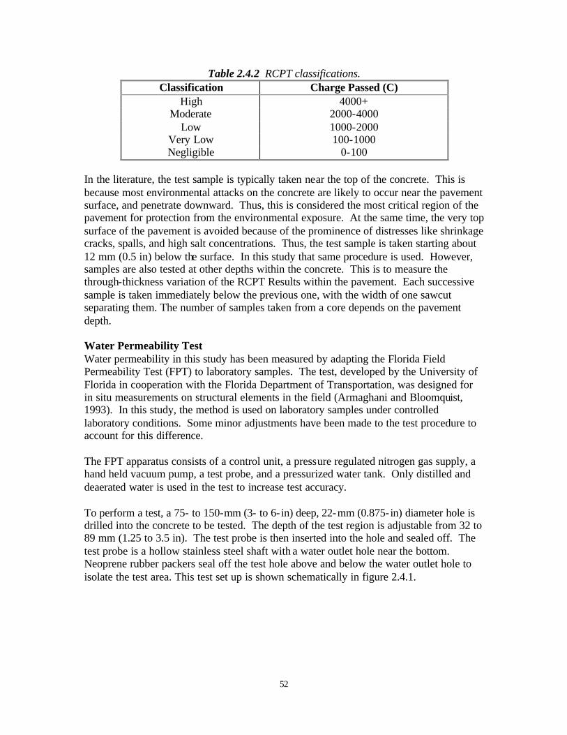
52
Table 2.4.2 RCPT classifications. Classification Charge Passed (C)
High 4000+ Moderate 2000-4000
Low 1000-2000 Very Low 100-1000 Negligible 0-100
In the literature, the test sample is typically taken near the top of the concrete. This is because most environmental attacks on the concrete are likely to occur near the pavement surface, and penetrate downward. Thus, this is considered the most critical region of the pavement for protection from the environmental exposure. At the same time, the very top surface of the pavement is avoided because of the prominence of distresses like shrinkage cracks, spalls, and high salt concentrations. Thus, the test sample is taken starting about 12 mm (0.5 in) below the surface. In this study that same procedure is used. However, samples are also tested at other depths within the concrete. This is to measure the through-thickness variation of the RCPT Results within the pavement. Each successive sample is taken immediately below the previous one, with the width of one sawcut separating them. The number of samples taken from a core depends on the pavement depth. Water Permeability Test Water permeability in this study has been measured by adapting the Florida Field Permeability Test (FPT) to laboratory samples. The test, developed by the University of Florida in cooperation with the Florida Department of Transportation, was designed for in situ measurements on structural elements in the field (Armaghani and Bloomquist, 1993). In this study, the method is used on laboratory samples under controlled laboratory conditions. Some minor adjustments have been made to the test procedure to account for this difference. The FPT apparatus consists of a control unit, a pressure regulated nitrogen gas supply, a hand held vacuum pump, a test probe, and a pressurized water tank. Only distilled and deaerated water is used in the test to increase test accuracy. To perform a test, a 75- to 150-mm (3- to 6- in) deep, 22-mm (0.875- in) diameter hole is drilled into the concrete to be tested. The depth of the test region is adjustable from 32 to 89 mm (1.25 to 3.5 in). The test probe is then inserted into the hole and sealed off. The test probe is a hollow stainless steel shaft with a water outlet hole near the bottom. Neoprene rubber packers seal off the test hole above and below the water outlet hole to isolate the test area. This test set up is shown schematically in figure 2.4.1.
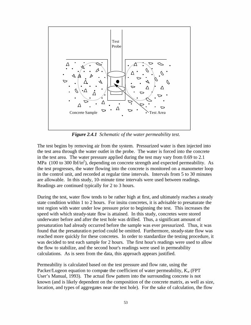
53
Figure 2.4.1 Schematic of the water permeability test. The test begins by removing air from the system. Pressurized water is then injected into the test area through the water outlet in the probe. The water is forced into the concrete in the test area. The water pressure applied during the test may vary from 0.69 to 2.1 MPa (100 to 300 lbf/in2), depending on concrete strength and expected permeability. As the test progresses, the water flowing into the concrete is monitored on a manometer loop in the control unit, and recorded at regular time intervals. Intervals from 5 to 30 minutes are allowable. In this study, 10-minute time intervals were used between readings. Readings are continued typically for 2 to 3 hours. During the test, water flow tends to be rather high at first, and ultimately reaches a steady state condition within 1 to 2 hours. For insitu concretes, it is advisable to presaturate the test region with water under low pressure prior to beginning the test. This increases the speed with which steady-state flow is attained. In this study, concretes were stored underwater before and after the test hole was drilled. Thus, a significant amount of presaturation had already occurred before the sample was ever pressurized. Thus, it was found that the presaturation period could be omitted. Furthermore, steady-state flow was reached more quickly for these concretes. In order to standardize the testing procedure, it was decided to test each sample for 2 hours. The first hour's readings were used to allow the flow to stabilize, and the second hour's readings were used in permeability calculations. As is seen from the data, this approach appears justified. Permeability is calculated based on the test pressure and flow rate, using the Packer/Lugeon equation to compute the coefficient of water permeability, Kw (FPT User’s Manual, 1993). The actual flow pattern into the surrounding concrete is not known (and is likely dependent on the composition of the concrete matrix, as well as size, location, and types of aggregates near the test hole). For the sake of calculation, the flow
Test Probe
Concrete Sample Test Area
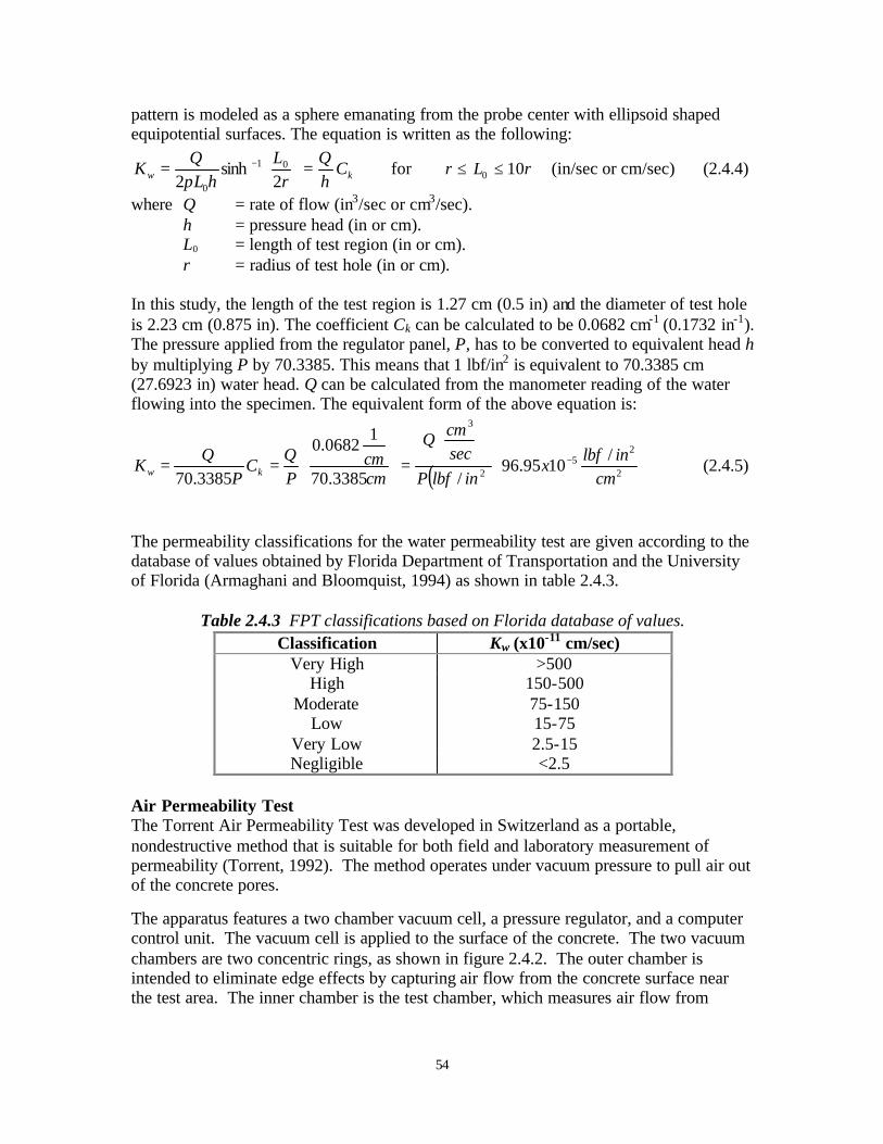
54
pattern is modeled as a sphere emanating from the probe center with ellipsoid shaped equipotential surfaces. The equation is written as the following:
kw ChQ
rL
hLQ
K =
= −
2sinh
201
0π for r L r≤ ≤0 10 (in/sec or cm/sec) (2.4.4)
where Q = rate of flow (in3/sec or cm3/sec). h = pressure head (in or cm). L0 = length of test region (in or cm). r = radius of test hole (in or cm). In this study, the length of the test region is 1.27 cm (0.5 in) and the diameter of test hole is 2.23 cm (0.875 in). The coefficient Ck can be calculated to be 0.0682 cm-1 (0.1732 in-1). The pressure applied from the regulator panel, P, has to be converted to equivalent head h by multiplying P by 70.3385. This means that 1 lbf/in2 is equivalent to 70.3385 cm (27.6923 in) water head. Q can be calculated from the manometer reading of the water flowing into the specimen. The equivalent form of the above equation is:
( )
=
== −2
25
2
3
/1095.96
/3385.70
10682.0
3385.70 cminlbf
xinlbfP
seccmQ
cmcm
PQ
CP
QK kw (2.4.5)
The permeability classifications for the water permeability test are given according to the database of values obtained by Florida Department of Transportation and the University of Florida (Armaghani and Bloomquist, 1994) as shown in table 2.4.3.
Table 2.4.3 FPT classifications based on Florida database of values.
Classification Kw (x10-11 cm/sec) Very High >500
High 150-500 Moderate 75-150
Low 15-75 Very Low 2.5-15 Negligible <2.5
Air Permeability Test The Torrent Air Permeability Test was developed in Switzerland as a portable, nondestructive method that is suitable for both field and laboratory measurement of permeability (Torrent, 1992). The method operates under vacuum pressure to pull air out of the concrete pores.
The apparatus features a two chamber vacuum cell, a pressure regulator, and a computer control unit. The vacuum cell is applied to the surface of the concrete. The two vacuum chambers are two concentric rings, as shown in figure 2.4.2. The outer chamber is intended to eliminate edge effects by capturing air flow from the concrete surface near the test area. The inner chamber is the test chamber, which measures air flow from
55
within the concrete at a right angle to the surface. The coefficient of permeability KT is calculated from results of the inner vacuum chamber.
Figure 2.4.2 Schematic of Torrent air permeability apparatus. [after Torrent, (1992)]
One permeability measurement takes 720 seconds. During the first 60 seconds, the vacuum pressure is obtained in the inner and outer chambers. A total pressure of 20 mbar or less is typical at the beginning of the test. After the initial vacuuming period, the inner chamber is shut off, and the loss of vacuum pressure over time is recorded. The outer chamber continues to pull vacuum in order to ensure no influence from the edges. The permeability KT is determined using equation 2.4.3 below.
∫
−
−
= dtPPP
PPAdtdPV
Ka
a
a
cT
2
1
2
21
2 1)(
/4
ηµ
(x 10-16 m2) (2.4.6)
where Vc = total volume to which the filling air had access (m3). µ = viscosity of air (2 x 10⁻⁵ Ns/m2). η = porosity of concrete. A = area (m2). P = pressure (mbars).
It should be noted that moisture in the concrete significantly influences the measured permeability, as water trapped in the pore spaces inhibits the flow of air. The more water present, the lower the measured permeability. Thus, the method is best suited for dry concretes, where moisture does not influence results. When moisture is present, separate
Inner Chamber
Outer Chamber
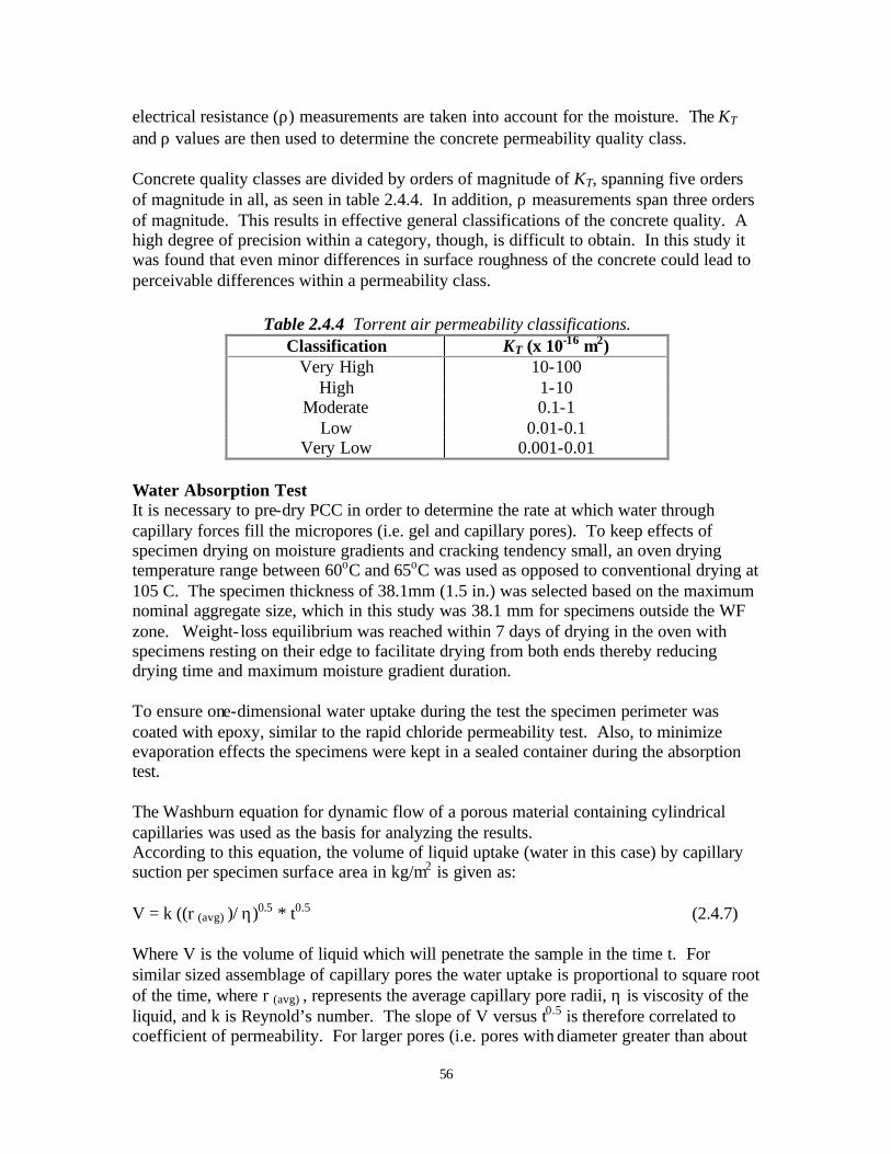
56
electrical resistance (ρ) measurements are taken into account for the moisture. The KT and ρ values are then used to determine the concrete permeability quality class. Concrete quality classes are divided by orders of magnitude of KT, spanning five orders of magnitude in all, as seen in table 2.4.4. In addition, ρ measurements span three orders of magnitude. This results in effective general classifications of the concrete quality. A high degree of precision within a category, though, is difficult to obtain. In this study it was found that even minor differences in surface roughness of the concrete could lead to perceivable differences within a permeability class.
Table 2.4.4 Torrent air permeability classifications. Classification KT (x 10-16 m2)
Very High 10-100 High 1-10
Moderate 0.1-1 Low 0.01-0.1
Very Low 0.001-0.01 Water Absorption Test It is necessary to pre-dry PCC in order to determine the rate at which water through capillary forces fill the micropores (i.e. gel and capillary pores). To keep effects of specimen drying on moisture gradients and cracking tendency small, an oven drying temperature range between 60oC and 65oC was used as opposed to conventional drying at 105 C. The specimen thickness of 38.1mm (1.5 in.) was selected based on the maximum nominal aggregate size, which in this study was 38.1 mm for specimens outside the WF zone. Weight- loss equilibrium was reached within 7 days of drying in the oven with specimens resting on their edge to facilitate drying from both ends thereby reducing drying time and maximum moisture gradient duration. To ensure one-dimensional water uptake during the test the specimen perimeter was coated with epoxy, similar to the rapid chloride permeability test. Also, to minimize evaporation effects the specimens were kept in a sealed container during the absorption test. The Washburn equation for dynamic flow of a porous material containing cylindrical capillaries was used as the basis for analyzing the results. According to this equation, the volume of liquid uptake (water in this case) by capillary suction per specimen surface area in kg/m2 is given as: V = k ((r (avg) )/ η)0.5 * t0.5 (2.4.7) Where V is the volume of liquid which will penetrate the sample in the time t. For similar sized assemblage of capillary pores the water uptake is proportional to square root of the time, where r (avg) , represents the average capillary pore radii, η is viscosity of the liquid, and k is Reynold’s number. The slope of V versus t0.5 is therefore correlated to coefficient of permeability. For larger pores (i.e. pores with diameter greater than about
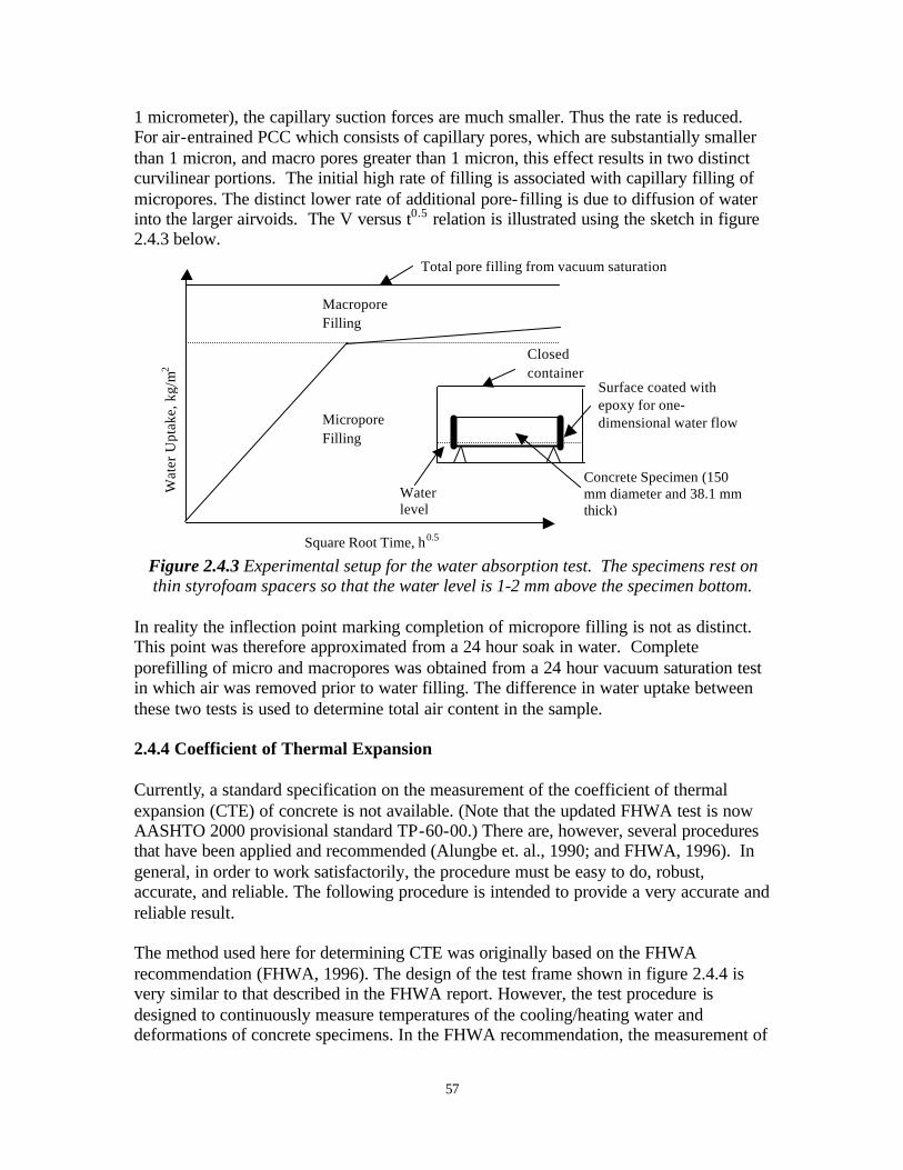
57
1 micrometer), the capillary suction forces are much smaller. Thus the rate is reduced. For air-entrained PCC which consists of capillary pores, which are substantially smaller than 1 micron, and macro pores greater than 1 micron, this effect results in two distinct curvilinear portions. The initial high rate of filling is associated with capillary filling of micropores. The distinct lower rate of additional pore-filling is due to diffusion of water into the larger airvoids. The V versus t0.5 relation is illustrated using the sketch in figure 2.4.3 below.
Figure 2.4.3 Experimental setup for the water absorption test. The specimens rest on thin styrofoam spacers so that the water level is 1-2 mm above the specimen bottom.
In reality the inflection point marking completion of micropore filling is not as distinct. This point was therefore approximated from a 24 hour soak in water. Complete porefilling of micro and macropores was obtained from a 24 hour vacuum saturation test in which air was removed prior to water filling. The difference in water uptake between these two tests is used to determine total air content in the sample. 2.4.4 Coefficient of Thermal Expansion Currently, a standard specification on the measurement of the coefficient of thermal expansion (CTE) of concrete is not available. (Note that the updated FHWA test is now AASHTO 2000 provisional standard TP-60-00.) There are, however, several procedures that have been applied and recommended (Alungbe et. al., 1990; and FHWA, 1996). In general, in order to work satisfactorily, the procedure must be easy to do, robust, accurate, and reliable. The following procedure is intended to provide a very accurate and reliable result. The method used here for determining CTE was originally based on the FHWA recommendation (FHWA, 1996). The design of the test frame shown in figure 2.4.4 is very similar to that described in the FHWA report. However, the test procedure is designed to continuously measure temperatures of the cooling/heating water and deformations of concrete specimens. In the FHWA recommendation, the measurement of
Wat
er U
ptak
e, k
g/m
2
Square Root Time, h0.5
Water level
Concrete Specimen (150 mm diameter and 38.1 mm thick)
Surface coated with epoxy for one-dimensional water flow
Closed container
Micropore Filling
Macropore Filling
Total pore filling from vacuum saturation
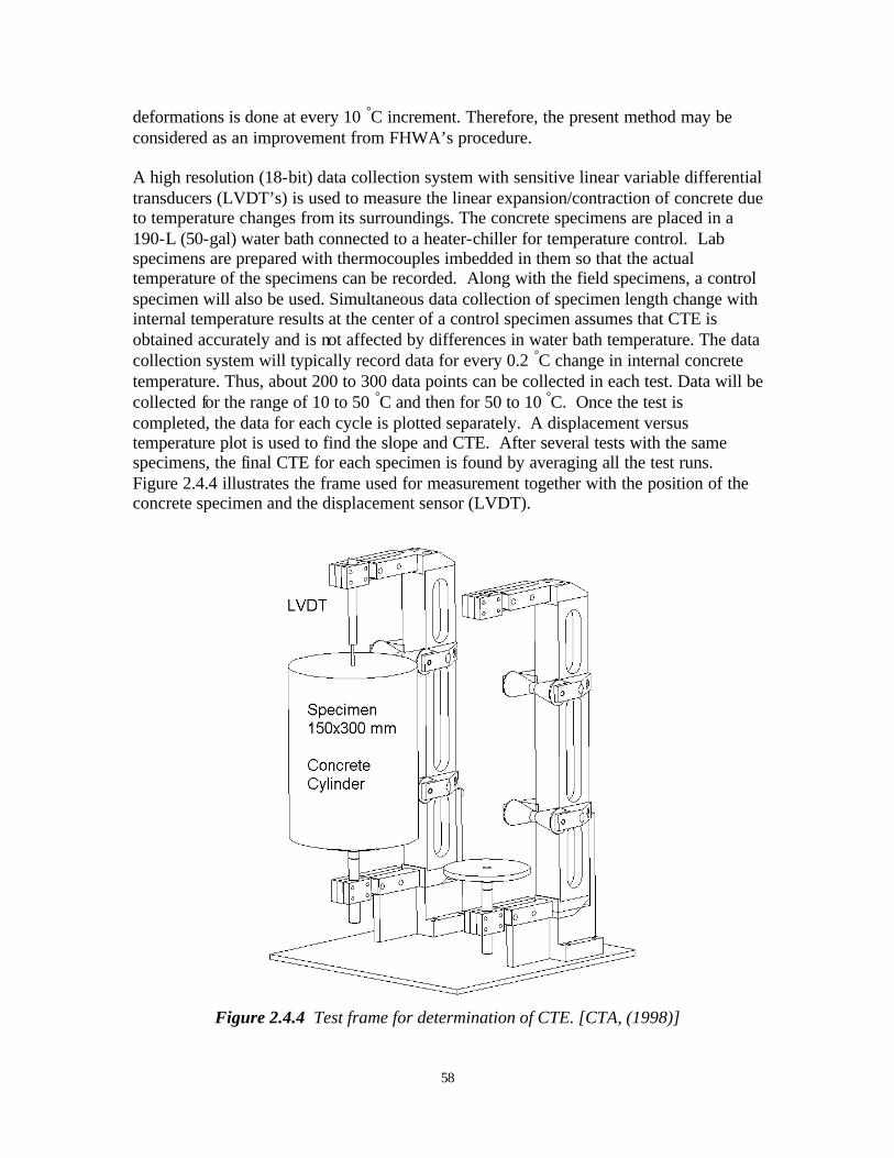
58
deformations is done at every 10 °C increment. Therefore, the present method may be considered as an improvement from FHWA’s procedure. A high resolution (18-bit) data collection system with sensitive linear variable differential transducers (LVDT’s) is used to measure the linear expansion/contraction of concrete due to temperature changes from its surroundings. The concrete specimens are placed in a 190-L (50-gal) water bath connected to a heater-chiller for temperature control. Lab specimens are prepared with thermocouples imbedded in them so that the actual temperature of the specimens can be recorded. Along with the field specimens, a control specimen will also be used. Simultaneous data collection of specimen length change with internal temperature results at the center of a control specimen assumes that CTE is obtained accurately and is not affected by differences in water bath temperature. The data collection system will typically record data for every 0.2 °C change in internal concrete temperature. Thus, about 200 to 300 data points can be collected in each test. Data will be collected for the range of 10 to 50 °C and then for 50 to 10 °C. Once the test is completed, the data for each cycle is plotted separately. A displacement versus temperature plot is used to find the slope and CTE. After several tests with the same specimens, the final CTE for each specimen is found by averaging all the test runs. Figure 2.4.4 illustrates the frame used for measurement together with the position of the concrete specimen and the displacement sensor (LVDT).
Figure 2.4.4 Test frame for determination of CTE. [CTA, (1998)]
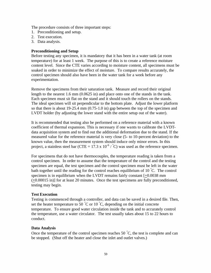
59
The procedure consists of three important steps: 1. Preconditioning and setup. 2. Test execution. 3. Data analysis. Preconditioning and Setup Before testing any specimen, it is mandatory that it has been in a water tank (at room temperature) for at least 1 week. The purpose of this is to create a reference moisture content level. Since the CTE varies according to moisture content, all specimens must be soaked in order to minimize the effect of moisture. To compare results accurately, the control specimen should also have been in the water tank for a week before any experimentation. Remove the specimens from their saturation tank. Measure and record their original length to the nearest 1.6 mm (0.0625 in) and place onto one of the stands in the tank. Each specimen must sit flat on the stand and it should touch the rollers on the stands. The ideal specimen will sit perpendicular to the bottom plate. Adjust the lower platform so that there is about 19-25.4 mm (0.75-1.0 in) gap between the top of the specimen and LVDT holder (by adjusting the lower stand with the entire setup out of the water). It is recommended that testing also be performed on a reference material with a known coefficient of thermal expansion. This is necessary if one wants to calibrate the LVDT-data acquisition system and to find out the additional deformation due to the stand. If the measured value for the reference material is very close (5- to 10-percent deviation) to the known value, then the measurement system should induce only minor errors. In this project, a stainless steel bar (CTE = 17.3 x 10⁻⁶ / °C) was used as the reference specimen. For specimens that do not have thermocouples, the temperature reading is taken from a control specimen. In order to assume that the temperature of the control and the testing specimen are equal, the test specimen and the control specimen must be left in the water bath together until the reading for the control reaches equilibrium of 10 °C. The control specimen is in equilibrium when the LVDT remains fairly constant [+0.0038 mm (+0.00015 in)] for at least 20 minutes. Once the test specimens are fully preconditioned, testing may begin. Test Execution Testing is commenced through a controller, and data can be saved in a desired file. Then, set the heater temperature to 50 °C or 10 °C, depending on the initial concrete temperature. To ensure good water circulation inside the tank and to accurately control the temperature, use a water circulator. The test usually takes about 15 to 22 hours to conduct. Data Analysis Once the temperature of the control specimen reaches 50 °C, the test is complete and can be stopped. (Shut off the heater and close the inlet and outlet valves.)
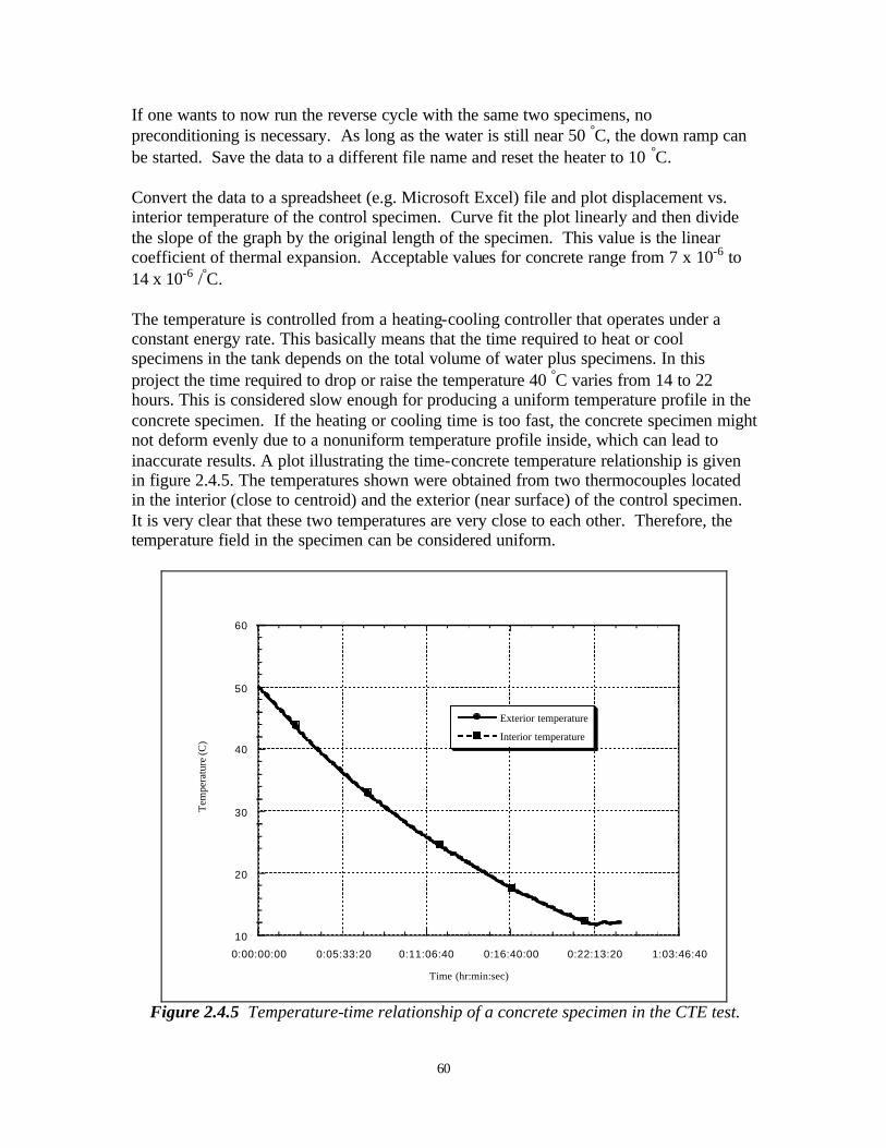
60
If one wants to now run the reverse cycle with the same two specimens, no preconditioning is necessary. As long as the water is still near 50 °C, the down ramp can be started. Save the data to a different file name and reset the heater to 10 °C. Convert the data to a spreadsheet (e.g. Microsoft Excel) file and plot displacement vs. interior temperature of the control specimen. Curve fit the plot linearly and then divide the slope of the graph by the original length of the specimen. This value is the linear coefficient of thermal expansion. Acceptable values for concrete range from 7 x 10⁻⁶ to 14 x 10-6 /°C. The temperature is controlled from a heating-cooling controller that operates under a constant energy rate. This basically means that the time required to heat or cool specimens in the tank depends on the total volume of water plus specimens. In this project the time required to drop or raise the temperature 40 °C varies from 14 to 22 hours. This is considered slow enough for producing a uniform temperature profile in the concrete specimen. If the heating or cooling time is too fast, the concrete specimen might not deform evenly due to a nonuniform temperature profile inside, which can lead to inaccurate results. A plot illustrating the time-concrete temperature relationship is given in figure 2.4.5. The temperatures shown were obtained from two thermocouples located in the interior (close to centroid) and the exterior (near surface) of the control specimen. It is very clear that these two temperatures are very close to each other. Therefore, the temperature field in the specimen can be considered uniform.
10
20
30
40
50
60
0:00:00:00 0:05:33:20 0:11:06:40 0:16:40:00 0:22:13:20 1:03:46:40
Exterior temperature
Interior temperature
Tem
pera
ture
(C)
Time (hr:min:sec)
Figure 2.4.5 Temperature-time relationship of a concrete specimen in the CTE test.
61
2.4.5 Petrographic Analysis of Cored Samples Concrete mix characteristics, which were found to have high influence on concrete distress from the literature review, are determined from the field cores using petrographic analysis. Although the mix design data are contained in the LTPP database, they may not be sufficiently accurate. The literature review indicates that the material characteristics most influential on the concrete pavement distress (spalling, cracking, and faulting) are w/c ratio, coarse aggregate (gradation, content, type) and entrained air. The coarse aggregate characteristics and air void parameters (paste content, total air) are measured on the field cores by the petrographers at the Michigan Department of Transportation according to ASTM C 856. Sample preparation procedures follow the guidelines of ASTM C 457. Petrographic analysis also documents if other internal distresses which have not yet reached the stage of visual detection are present. Such distresses include D-cracking, ASR, plastic shrinkage and drying shrinkage cracking. These distresses are determined using low power stereo microscopy and thin section microscopy. Estimates of w/c ratio have been made in this study by the Michigan Technological University using the maleic acid technique, as described in appendix C.