the effects of outrigger type and distribution on seismic
TRANSCRIPT

Computational Engineering and Physical Modeling 1-3 (2018) 67-78
How to cite this article: Ahani A, Ahani E, Abbaszadeh H. The Effects of Outrigger Type and Distribution on Seismic Behavior of
Super-Tall Building. Comput Eng Phys Model 2018;1(3):67–78. https://doi.org/10.22115/cepm.2018.125321.1016
2588-6959/ © 2018 The Authors. Published by Pouyan Press.
This is an open access article under the CC BY license (http://creativecommons.org/licenses/by/4.0/).
Contents lists available at CEPM
Computational Engineering and Physical Modeling
Journal homepage: www.jcepm.com
The Effects of Outrigger Type and Distribution on Seismic
Behavior of Super-Tall Building
A. Ahani1*, E. Ahani2, H. Abbaszadeh1
1. M.Sc. Student, Department of Civil Engineering, Istanbul Technical University, Istanbul, Turkey
2. M.Sc. Graduate of Structural Engineering, Sahand University of Technology, Tabriz, Iran
Corresponding author: [email protected]
https://doi.org/10.22115/CEPM.2018.125321.1016
ARTICLE INFO
ABSTRACT
Article history:
Received: 17 March 2018
Revised: 18 September 2018
Accepted: 18 February 2019
Seismic performance and behavior of super-tall building is
one of significant place of doubt while using energy
dissipated outriggers. To enhance the seismic performance of
super-tall building structures using outrigger is one common
method; however, the performance and behavior of the
outrigger varies based on the outrigger section and more
importantly the elevation and multitude of outrigger in
structure, that could cause great differences in seismic
behavior of outrigger and the compressive force that is going
to apply to mega columns. To evaluate the seismic
performance of the building, a case study was carried out.
The models was provided with two different outrigger and
two different outrigger distribution and results was find out
for each model to compare and present the best model that
has the higher performance in whole building. The numerical
models for the structures in different condition were
established with the aid of ETABS software. The responses
of the modeled buildings were obtained for TSC 2007 and
TSC 2017 and compared. The results show that using
outrigger at roof level could significantly affect the story
displacement; however, it increases the periods at both X and
Y directions.
Keywords:
Super-tall building;
Outrigger system;
Seismic behavior;
Numerical modeling.
68 A.Ahani et al./Computational Engineering and Physical Modeling 1-3 (2018) 67-78
1. Introduction
One of the best ways to withstand and bear lateral loads in super tall buildings are use and
implementation of outrigger system. Outrigger system is consist of shear walls which acts as a
central core and outrigger trusses or deep girders which connecting the central core to the mega
columns. The efficiency of a structural system in withstanding lateral is evaluated in terms of its
ability to resist great lateral loads, which increases as the height of the building increase. In
design of super-tall buildings, stability and stiffness are more significant than strength to resist
greater lateral and gravity loads [1].
For example, with the economic amendment and rapid urbanization in China, many skyscrapers
have been constructed or are under construction. A large part of these high-rise buildings utilize
hybrid steel-concrete structure systems such as Steel Frame-Reinforced Concrete (RC) core
tubes, due to their unique advantage in reducing construction costs and time. To reduce the inter-
story drift of super-tall buildings under earthquakes and winds, the outer frame and the core tube
are usually linked together by outriggers to reinforce a story. However, in presence of the
outriggers, the lateral stiffness is much larger at the strengthened story than that of the adjacent
stories, which has led to a sudden change in the internal forces in the structural members of such
stories and the possible configuration of weak stories under serious earthquakes [2].
Most usual systems which are used for withstanding lateral loads in tall steel buildings are
moment resisting frames and braced frames. In moment resisting frames yielding causes
ductility, but due to their flexibility fails to provide enough stiffness; however, braced frames
provide required stiffness. The various concentric bracing forms are efficient in seismic
performance. Patil et al. studied Seismic performance of different braced 2-D high rise buildings
for different story height [3]. Eccentric bracing and knee bracing are bracing systems which are
dissipating energy by yielding of the shear walls and knee elements, these bracing systems are
also very effective in seismic performance (Roeder and Popov) [4], Hjelmstad and Popov [5] and
Balendra et al. [6–8]). However, outrigger systems increases the stiffness of super-tall buildings
by the introduction of stiff outriggers at different locations (Patil and Sangle [9]).
Taranath [10] has examined the theoretical approach to outrigger braced frames by assuming a
tall building as a cantilever beam with rotational springs at various story heights on the lateral
load resisting system. The equations which were optimizing the location of the springs were used
as simple as possible [11]. In addition, an investigation with a uniform and non-uniform truss
belt under inverted triangular and uniform lateral loadings. A graphical approach is also provided
for the analysis of braced frames with horizontal load-bearing outrigger trusses. This procedure
follows a simple approach to find the optimal location for the outrigger through the height of the
structure and a quick assessment of the behavior of the outrigger braced super-tall structure. A
graphical analysis method is also proposed to optimize the position of outriggers on shear walls
[12]. Hoenderkamp and Sniedder [13] provided a simple method for analyzing the face of the
outriggers with solid frames in high-rise buildings subjected to horizontal loading. Previously, a
simple graphical method for analysis was given to provide the desired outrigger location in a
super-tall shear wall structures and reinforced concrete shear wall-steel truss with a perimeter

A.Ahani et al./Computational Engineering and Physical Modeling 1-3 (2018) 67-78 69
belt structure [14,15]. A manual calculation model for a graphical technique is provided to
estimate the overall performance of a steel outrigger structure with a concrete shear walls under
wind load. An approximate analysis method is presented to calculate the natural vibrational
periods for super-tall steel buildings included braced frames with outrigger trusses. This method
is proposed for the relationship between the natural frequencies of the structure and the top
deflection and rotation [16].
The conventional continuum method is represented to obtaining the effect of the location of the
outrigger by Zeidabadi et al. [17]. The governing equations of wall-frame structures with
outriggers formulated through the continuum approach idealizing the whole structure as a shear–
flexural cantilever with rotational springs. Combined systems of the shear core, framed tube, and
outrigger-belt truss which are implemented in Super-tall building structures are modelled using
continuum approach. The optimized location of concentrated, uniform and triangular load was
extracted for outrigger truss belt system [18]. Belt trusses and basements acts as virtual
outriggers for super-tall buildings. However, virtual outriggers has less effect than conventional
direct outriggers due to the decrease in stiffness of the indirect force transfer method [19]. The
basic design optimization procedure of super-tall buildings performed mainly for lateral wind
loads to find the optimum locations and a number of outriggers in super-tall buildings [20]. Other
significant parameters such as drift and moments on the shear walls monitored for different
outrigger locations in super-tall buildings.
Existence of outriggers at various levels of the building increase stiffness of the building in
lateral direction. An approximate analysis of the complex multi-outrigger braced structure is
presented based on a continuous method using a set of outriggers. By increase in outrigger
numbers, the provided results become more reliable and accurate [21]. Furthermore, Wu and Li
[22] evaluated the optimum design of outriggers in tall buildings. The effects of the outriggers
locations on drift, core reaction force and the period of the high-rise structures are presented.
Bayati et al. [23] demonstrated drift reduction in uniform belted structures with rigid outriggers.
In this study by using optimized multi-outriggers system dimensions of elements and foundation
were decreased. Fawzia and Fatima [24] by provision of truss belt and outrigger system adjust
the deflection of composite building subjected to wind loads. The corresponding reductions in
lateral deflection for one, two and three outrigger systems are 34%, 42% and 51% respectively.
Fawzia et al. [25] Examines the effects of a cyclic wind on buildings in which outrigger systems
implemented. Increase in height of the building and keeping the dimensions of the building plan
reduces the lateral rigidity. Therefore, it was necessary to obtain stiffness by increase on bracing
size and provision of additional lateral resisting system such as truss belt and outriggers.
Furthermore, the super-tall buildings which are composed of different combined lateral load
systems studied by some researchers. Brunesi et al. [26] investigated super-tall buildings with
outriggers and belt trusses using fiber based finite element model archetype. Seismic
performance is evaluated based on effects of bracing and outrigger belted truss. In addition, Fan
et al. [27] studied the Taipei financial center which is composed of concrete filled steel tube
columns, steel brace core and belt. The computational results shows that the super-tall building
with the mega-frame system have very great ability to reserve strength, and the super-tall

70 A.Ahani et al./Computational Engineering and Physical Modeling 1-3 (2018) 67-78
building would satisfy the design needs under different seismic events. In addition, Lu et al. [28]
studied the collapse behavior of a super-tall mega-braced frame core tube building which is 550
meters high in the high risk seismic zone. A finite element model is created based on the fiber-
beam and multi-layer shell models. The failure mode and mechanism of earthquake-induced
collapse are studied. It is obtained from previous studies that the optimum location of outrigger
in super-tall buildings is mainly evaluate on wind loadings. Therefore investigating the behavior
of outrigger braced systems in high-rise buildings is essential.
This paper aims to provide some significant information on seismic behavior of super-tall
building models, as the goal of this study is to represent the effect of outrigger type and location
the multitude of outriggers keeps constant (3 outrigger) in each model. In addition, effect of
outrigger type and location for two types of outrigger and two different distribution (location)
was obtained and seismic behavior of them assessed based on TSC 2007 and TSC 2017.
2. Case study and modeling
International Finance Centre building plan and elevation in Hong Kong was chosen for this
research as case study that consist of 89 floor (415 meters). Fig. 1a shows the structural plan that
was used in modeling. Material properties and concrete that was used in structure was shown in
Table 1 while Table 2 depicts material strength, elastic modulus and density in more detail. In
addition, Table 3 represents the mega column, secondary columns, outriggers, and belt trusses
details.
Table 1 Material Properties.
Outrigger Column Belt truss Shear walls
(core) Beam
Concrete - C28 - C28 -
Steel ST37 - ST37 - ST37
Reinforcement - - - AII -
Table 2 Material Characteristics.
f’c (Mpa)
E
(Mpa)
Density
(kN/m3)
Density
(kg/m3)
Concrete 28 25000 23.561 2402
fy
(Mpa)
fu
(Mpa)
E
(Gpa)
Density
(kN/m3)
Density
(kg/m3)
Steel 400 600 200 76.929 7849.097
Reinforcement 240 360 200 76.929 7849.097

A.Ahani et al./Computational Engineering and Physical Modeling 1-3 (2018) 67-78 71
Distribution 1 is consist of three outrigger that was set on between floors number 21-23, 45-47,
and 67-69; and Distribution 2 is consist of three outrigger like previous distribution that was
applied between floors number 28-30, 58-60, and 87-89. There are four different case that was
investigated in this study case (1) using outrigger I and distribution 1, case (2) using outrigger I
and distribution 2, case (3) using outrigger II and distribution 1, and case (4) using outrigger II
and distribution 2. Fig. 4c shows the belt truss that was used in this research the belt truss
consider to be constant to have better comparison of seismic performance due to change in either
outrigger type or outrigger location.
Fig. 1. Typical Plan of case study.
The seismic analysis of current study was response spectrum analysis based on the envelope
curve of standard spectrum in TSC 2007 and TSC 2017. According to TSC 2007 building
importance factor (I) should be got 1 for the intensive short-term buildings. Ground acceleration
(A0) considered 0.4g in which g is Gravitational acceleration. The local site class of the studied
model is Z2 which is used for dense sand, gravel, stiff and very stiff clay and silty clay.
Parameters that have been extracted form TSC 2017 was partially different from TSC 2007 but
building importance factor and ground acceleration was same as TSC 2007. While building
distance from fault parameter was introduced, local site according to TSC 2017 was appointed
ZC. Response spectrum for both codes is illustrated in Fig. 2. Envelope of the response
spectrums for analyzing of the building used. While the spectrum curve of TSC 2017 is rigorous
in lower periods the curve is more conservative for tall building in TSC 2007.
Fig. 3 shows elevation by considering outrigger, and shows elevation consist of belt trusses. As it
is illustrated in figure, distribution of outrigger and belt truss was changed; however, type of belt
trusses keep constant.

72 A.Ahani et al./Computational Engineering and Physical Modeling 1-3 (2018) 67-78
Fig. 2. Standard response spectrum of TSC 2007 and TSC 2017.
Fig. 3. Elevation with a) belt truss distribution 1, b) belt truss distribution 2, c) outrigger type I,
distribution 1, d) outrigger type I, distribution 2, e) outrigger type II, distribution 1, and f) outrigger type
II, distribution 2.
Table 3 Elements Details.
Type
(section)
Largest
length
(m)
Width
(m)
Thickness
(mm)
Area
(cm2)
Outrigger I Tube 12.04 0.9 90 2916
Outrigger II Tube 13.02 0.9 90 2916
Mega columns Filled Tube 4 2 80 40000
Secondary columns Filled Tube 4 0.8 30 1600
Shear Walls (core) Reinforced Concrete 4 - 2000 20000
Slab Reinforced Concrete 10.5 9 200 -
Beam IPE 270 10.5 0.135 0.01-0.006 45.9
0
0.2
0.4
0.6
0.8
1
1.2
1.4
1.6
0 2 4 6 8 10 12
Res
po
nse
Sp
ectr
a
Building Period (s)
TSC 2017
TSC
2007

A.Ahani et al./Computational Engineering and Physical Modeling 1-3 (2018) 67-78 73
In models designing at ETABS software outrigger sections was continued in two upper and
lower stories inside the core (shear walls) to reach the higher stiffness in whole mode and this is
performed at all cases.
Fig. 4. Sections of a) Outrigger type I, b) Outrigger type II, and c) Belt truss.
In addition, Fig. 4a shows the outrigger type 1 and its detail properties were shown in Table 3.
Fig. 4b shows the outrigger type II for this study and detailed information was given in Table 3.
Fig. 5 shows the mega columns section, detailed information about sections could be find in
Table 3. It should be noted due to overlap of shear walls and floor slabs, in ETABS modification
factor, 0.95 value assigned to weight and mass. Beams connections are pinned-pinned at models.
Fig. 5. Mega column type section (2 (m) – 0.1 (m)).
74 A.Ahani et al./Computational Engineering and Physical Modeling 1-3 (2018) 67-78
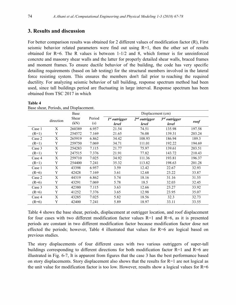
3. Results and discussion
For better comparison results was obtained for 2 different values of modification factor (R), First
seismic behavior related parameters were find out using R=1, then the other set of results
obtained for R=6. The R values is between 1-1/2 and 8, which former is for unreinforced
concrete and masonry shear walls and the latter for properly detailed shear walls, braced frames
and moment frames. To ensure ductile behavior of the building, the code has very specific
detailing requirements (based on lab testing) for the structural members involved in the lateral
force resisting system. This ensures the members don't fail prior to reaching the required
ductility. For analyzing seismic behavior of tall building, response spectrum method had been
used, since tall buildings period are fluctuating in large interval. Response spectrum has been
obtained from TSC 2017 in which
Table 4 Base shear, Periods, and Displacement.
Table 4 shows the base shear, periods, displacement at outrigger location, and roof displacement
for four cases with two different modification factor values R=1 and R=6, as it is presented
periods are constant in two different modification factor because modification factor dose not
effected the periods; however, Table 4 illustrated that values for R=6 are logical based on
previous studies.
The story displacements of four different cases with two various outriggers of super-tall
buildings corresponding to different directions for both modification factor R=1 and R=6 are
illustrated in Fig. 6-7, It is apparent from figures that the case 3 has the best performance based
on story displacements. Story displacement also shows that the results for R=1 are not logical as
the unit value for modification factor is too low. However, results show a logical values for R=6
direction
Base
Shear
(kN)
Period
(s)
Displacement (cm)
1st outrigger
level
2nd outrigger
level
3rd outrigger
level roof
Case 1 X 260389 6.957 21.54 74.51 135.98 197.58
(R=1) Y 254572 7.169 21.65 76.08 139.31 203.24
Case 2 X 265919 6.862 34.42 108.93 186.94 189.3
(R=1) Y 259750 7.069 34.71 111.01 192.22 194.69
Case 3 X 254283 7.115 21.77 75.97 139.61 203.51
(R=1) Y 247515 7.376 21.91 77.82 143.72 210.43
Case 4 X 259710 7.025 34.92 111.36 193.81 196.37
(R=1) Y 254400 7.241 35.32 113.82 198.63 201.28
Case 1 X 43398 6.957 3.59 12.42 22.67 32.93
(R=6) Y 42428 7.169 3.61 12.68 23.22 33.87
Case 2 X 44319 6.862 5.74 18.16 31.16 31.55
(R=6) Y 43291 7.069 5.78 18.5 32.03 32.45
Case 3 X 42380 7.115 3.63 12.66 23.27 33.92
(R=6) Y 41252 7.376 3.65 12.98 23.95 35.07
Case 4 X 43285 7.025 5.82 18.56 32.3 32.73
(R=6) Y 42400 7.241 5.89 18.97 33.11 33.55

A.Ahani et al./Computational Engineering and Physical Modeling 1-3 (2018) 67-78 75
of roof displacement 300-350 (mm) that is acceptable for this structures. Story drifts of four
cases for X and Y direction is depicted in Fig. 8.
Base shear amount is greater in X-direction compared with Y-direction either in R=1 or in R=6
condition. Fig. 9a illustrate the base shears for all four cases with two different R, as it is shown
there is a great differences between R=1 and R=6 base shears. Base shear values in all four cases
are so close and there is no great difference among cases.
In addition, periods for all cases in both X and Y direction was shown at Fig. 9b. Periods in X-
direction in all cases are lower than Y-direction periods. Fig.9b shows that case 2 has the lowest
period; however, case 3 has the greatest period among cases.
Fig. 10 shows the deformations of all cases in both X and Y directions, as it is illustrated case 1
and case 4 has the lowest deformation compared others. In case 2 outrigger type I used that has
greater stiffness than outrigger type 2 that was used in case 3; however, their deformation
obtained approximately equal that is effected from distribution of outrigger. Thus, using
outrigger at roof level (outrigger distribution) could change the behavior of structure
significantly.
Fig. 6. Story-Displacement curves in X and Y directions for R=1.
Fig. 7. Story-Displacement curves in X and Y directions for R=6.
0
10
20
30
40
50
60
70
80
90
100
0 500 1000 1500 2000 2500
Sto
ry
Displacement (m)
Displacement in Y-direction
Case 1
Case 2
Case 3
Case 4
0
20
40
60
80
100
0 100 200 300 400
Sto
ry
Displacement (m)
Displacement in X-direction
Case 1
Case 2
Case 3
Case 4
0
20
40
60
80
100
0 100 200 300 400
Sto
ry
Displacement (m)
Displacement in Y-direction
Case 1
Case 2
Case 3
Case 4
0
10
20
30
40
50
60
70
80
90
100
0 500 1000 1500 2000 2500
Sto
ry
Displacement (m)
Displacement in X-direction
Case 1
Case 2
Case 3
Case 4

76 A.Ahani et al./Computational Engineering and Physical Modeling 1-3 (2018) 67-78
Fig. 8. Story Drift of Studied systems on X and Y direction.
Fig. 9. a) Base shears, and b) Periods.
Fig. 10. Deformations for TSC 2017 (R=1) a) case 1, b) case 2, c) case 3, and d) case 4.
0102030405060708090
0 0.1 0.2 0.3 0.4 0.5 0.6 0.7 0.8 0.9 1
Sto
ry N
o.
Drift (%)
X-Direction R=1
Case 1Case 2Case 3Case 4
0102030405060708090
0 0.05 0.1 0.15 0.2
Sto
ry N
o.
Drift (%)
X-Direction R=6
Case 1Case 2Case 3Case 4
0102030405060708090
0 0.1 0.2 0.3 0.4 0.5 0.6 0.7 0.8 0.9 1
Sto
ry N
o.
Drift (%)
Y-Direction R=1
Case 1Case 2Case 3Case 4
0102030405060708090
0 0.05 0.1 0.15 0.2
Sto
ry N
o.
Drift (%)
Y-Direction R=6
Case 1Case 2Case 3Case 4

A.Ahani et al./Computational Engineering and Physical Modeling 1-3 (2018) 67-78 77
4. Conclusion
In this work an attempt is made to evaluate the seismic performance of four different super-tall
outrigger braced building to determine the seismic behavior of each model with different
outrigger type and different outrigger distribution. For this purpose, the models were analyzed
using ETABS software and results for base shear, period, story displacement was find out for all
cases and comparison was made based on them.
Results for base shears in Table 3 showed that there is not such great different in base shear
amount among cases and it is approximately equal to 250000 (kN) for R=1, and 4300 (kN) for
R=6 either at X or at Y direction.
Periods are lower at X-direction compared to Y-direction. Case 2 has the lowest period
(T=6.862 (s)), and case 3 reaches the greatest period (T=7.376 (s)).
Story displacement at Y-direction are greater than displacement at X-direction in all cases
and different R values. In either R=1 or R=6 and in both directions case 3 has the greatest and
case 2 has the lowest displacement (see Fig. 5-6).
Further addition of second and third outrigger in the outrigger braced buildings increases the
base shear with decreasing the story displacement.
By considering that stiffness of outrigger type I is greater than outrigger type 2, case 2 with
outrigger type 2 and distribution 2 gives the lowest story displacement. Thus, it is found that
distribution is significantly influenced the story displacement and using outrigger at roof level
could affect the result.
References
[1] Taranath BS. Structural analysis and design of tall buildings: Steel and composite construction.
CRC press; 2016.
[2] Kamath K. A Study on Static and Dynamic Behavior of Outrigger Structural System for Tall
Buildings. Bonfring Int J Ind Eng Manag Sci 2012;2:15–20. doi:10.9756/BIJIEMS.1655.
[3] Patil DM, Sangle KK. Seismic Behaviour of Different Bracing Systems in High Rise 2-D Steel
Buildings. Structures 2015;3:282–305. doi:10.1016/j.istruc.2015.06.004.
[4] Roeder CW, Popov EP. Eccentrically braced steel frames for earthquakes. J Struct Div
1978;104:391–412.
[5] Hjelmstad KD, Popov EP. Characteristics of Eccentrically Braced Frames. J Struct Eng
1984;110:340–53. doi:10.1061/(ASCE)0733-9445(1984)110:2(340).
[6] Balendra T, Sam M-T, Liaw C-Y, Lee S-L. Preliminary studies into the behaviour of knee braced
frames subject to seismic loading. Eng Struct 1991;13:67–74. doi:10.1016/0141-0296(91)90010-A.
[7] Balendra T, Sam MT, Liaw CY. Design of earthquake-resistant steel frames with knee bracing. J
Constr Steel Res 1991;18:193–208. doi:10.1016/0143-974X(91)90025-V.
[8] Sam M-T, Balendra T, Liaw C-Y. Earthquake-resistant steel frames with energy dissipating knee
elements. Eng Struct 1995;17:334–43. doi:10.1016/0141-0296(95)00016-Z.
[9] Patil DM, Sangle KK. Seismic Behaviour of Outrigger Braced Systems in High Rise 2-D Steel
Buildings. Structures 2016;8:1–16. doi:10.1016/j.istruc.2016.07.005.
78 A.Ahani et al./Computational Engineering and Physical Modeling 1-3 (2018) 67-78
[10] Taranath BS. Optimum belt truss location for high-rise structures. Struct Eng 1975;53:18–21.
[11] Smith BS, Salim I. Formulae for optimum drift resistance of outrigger braced tall building
structures. Comput Struct 1983;17:45–50. doi:10.1016/0045-7949(83)90027-5.
[12] Hoenderkamp JCD, Bakker MCM. Analysis of high-rise braced frames with outriggers. Struct Des
Tall Spec Build 2003;12:335–50. doi:10.1002/tal.226.
[13] Hoenderkamp JCD, Snijder HH. Preliminary Analysis of High-Rise Braced Frames with Facade
Riggers. J Struct Eng 2003;129:640–7. doi:10.1061/(ASCE)0733-9445(2003)129:5(640).
[14] HOENDERKAMP JCD. Shear wall with outrigger trusses on wall and column foundations. Struct
Des Tall Spec Build 2004;13:73–87. doi:10.1002/tal.235.
[15] Hoenderkamp JCD, Snijder HH, Hofmeyer H. High-Rise Structures with Belt Bracing Subject to
Lateral Load. Adv Struct Eng 2012;15:65–75. doi:10.1260/1369-4332.15.1.65.
[16] Nicoreac M, Hoenderkamp JCD. Periods of Vibration of Braced Frames with Outriggers. Procedia
Eng 2012;40:298–303. doi:10.1016/j.proeng.2012.07.098.
[17] ZEIDABADI NA, MIRTALAE K, MOBASHER B. Optimized use of the outrigger system to
stiffen the coupled shear walls in tall buildings. Struct Des Tall Spec Build 2004;13:9–27.
doi:10.1002/tal.228.
[18] Lee J, Bang M, Kim J-Y. An analytical model for high-rise wall-frame structures with outriggers.
Struct Des Tall Spec Build 2008;17:839–51. doi:10.1002/tal.406.
[19] Nair RS. Belt trusses and basements as" virtual" outriggers for tall buildings. Eng Journal-
American Inst Steel Constr 1998;35:140–6.
[20] Gerasimidis S, Efthymiou E, Baniotopoulos CC. Optimum outrigger locations of high-rise steel
buildings for wind loading. EACWE 5, Florence Italy 2009.
[21] Coull A, Lau WHO. Analysis of Multioutrigger‐Braced Structures. J Struct Eng 1989;115:1811–5.
doi:10.1061/(ASCE)0733-9445(1989)115:7(1811).
[22] Wu JR, Li QS. Structural performance of multi-outrigger-braced tall buildings. Struct Des Tall
Spec Build 2003;12:155–76. doi:10.1002/tal.219.
[23] Bayati Z, Mahdikhani M, Rahaei A. Optimized use of multi-outriggers system to stiffen tall
buildings. 14th World Conf. Earthq. Eng., 2008, p. 40–4.
[24] Fawzia S, Fatima T. Deflection control in composite building by using belt truss and outriggers
system. Proc. 2010 World Acad. Sci. Eng. Technol. Conf., 2010.
[25] Fatima T, Fawzia S, Nasir A. Study of the effectiveness of outrigger system for high-rise composite
buildings for cyclonic region. ICECECE 2011 Int. Conf. Electr. Comput. Electron. Commun. Eng.,
WASET; 2011, p. 937–45.
[26] Brunesi E, Nascimbene R, Casagrande L. Seismic analysis of high-rise mega-braced frame-core
buildings. Eng Struct 2016;115:1–17. doi:10.1016/j.engstruct.2016.02.019.
[27] Fan H, Li QS, Tuan AY, Xu L. Seismic analysis of the world’s tallest building. J Constr Steel Res
2009;65:1206–15. doi:10.1016/j.jcsr.2008.10.005.
[28] Lu X, Lu X, Guan H, Zhang W, Ye L. Earthquake-induced collapse simulation of a super-tall
mega-braced frame-core tube building. J Constr Steel Res 2013;82:59–71.
doi:10.1016/j.jcsr.2012.12.004.