the efficiency rate of a steam-water injector · the efficiency rate of a steam-water injector masa...
TRANSCRIPT
Acta Polytechnica Hungarica Vol. 9, No. 5, 2012
– 107 –
The Efficiency Rate of a Steam-Water Injector
Masa Bukurov, Sinisa Bikic, Miljana Prica
University of Novi Sad, Faculty of Technical Sciences
Trg Dositeja Obradovica 6, 21000 Novi Sad
[email protected], [email protected], [email protected]
Abstract: This paper analyses the influence of relevant parameters on the efficiency rate of
a supersonic injector and its parts. Forced condensation in the injector is achieved by the
mixing of cold water and steam with the goal of getting higher pressures of hot water (6-12
bar) with an outlet temperature of 70-80 C to enable distant transportation of hot water
and heating. Although the energy potential of pressure is not significant compared to inlet
energy of steam, it is of importance since it represents the potential to realize external
work. The complex flow process through the mixing chamber, the most important part of
the injector, is presented with a diagram of forced condensation energy change, flow and
geometry changes of the mixing chamber and the distribution of the relevant forces on the
borders of the mixing chamber. It is shown that higher efficiency rates are achieved if
condensation is speeded up by the reduced mixing of cold water and steam. Analyses are
done according to analytical laws and experimental investigations of a steam-water
injector prototype, with the data enclosed. The efficiency rates of the mixing chamber
ranges from 60 to 85%, depending upon the following: the injection coefficient, the inlet
pressures and the temperatures of the cold water and steam (and the desired outlet hot
water temperature and pressure). Investigations are mostly directed to the particular needs
of energy and process devices and the significance of the Mach number was not especially
emphasized in them.
Keywords: steam-water injector; efficiency rate; supersonic steam-water injector; forced
condensation
1 Introduction
The main purpose of the considered steam-water injector is to substitute the pump
and heat exchanger, which is a great challenge for numerous applications [1, 2].
The relatively cheap acquisition of a steam boiler with low-demanded
performances eliminates the need for electric energy supply and makes possible
the autonomy of certain process. The remaining important question is if it is
possible to get low outlet temperature and relatively high pressure (6-12 bar,
5w sm m ) with a steam-water injector.

M. Bukurov et al. The Efficiency Rate of a Steam-Water Injector
– 108 –
Due to very high velocities of steam (vs) at the outlet of Laval nozzle of about
600-800 m/s, velocities of mixture through mixing chamber (vmix mc) are also high,
so the whole flow process of mixing and condensation happens very fast. It is of
importance that the transition from supersonic into subsonic flow is realized in
vicinity of the throat of mixing chamber, which, as a matter of fact, occurs no
matter if all steam is condensed or water is completely mixed with condensate.
This fact, experimentally confirmed, indicates that the homogeneity of flow field
and uniform mixing are not necessary in order to achieve the transition from
supersonic into subsonic flow at the end of mixing chamber or near to it.
Sound velocity (c), i.e. the Mach number (M), is the main criterion for such a
complex and quick energy flow process through mixing chamber, which is in
accordance with dynamic equation of compressible flow without losses in which
balance of flow is reached by equilibrium of only inertial and elastic
(compressible) forces. Isentropic-polytrophic changes of flow parameters in the
transition zone (M1), shown in diagram in Fig. 1 [3, 4], are valid also for the
flow in vicinity of the mixing chamber throat. Smooth transition - without shocks
- from supersonic into subsonic flow is achieved also during experimental
investigations.
Figure 1
Steam-water mixture polytrophic changes of pressure (p) and velocity (v) through mixing chamber for
supersonic transition as a function of Mach number (M) and cross-section change dA
The energy diagram, which is very important for the physical representation and
analysis of flow, can be gained indirectly in this case, thanks to the energy
diagram of forced condensation. The modified Mollier’s diagram of forced
condensation, connected with longitudinal geometry change (change of the cross
section) of the mixing chamber, accurately presents energy changes along mixing
chamber (p, t, h).
The application of reliable momentum equation, which is valid without any
limitations for flow process in the mixing chamber, gives data about the pressure
change in it, depending on the inlet and outlet parameters.

Acta Polytechnica Hungarica Vol. 9, No. 5, 2012
– 109 –
The efficiency rate of the steam-water injector inj is presented with:
inj L cwnozz mc d (1)
where
L+cw nozz – is the efficiency rate of the Laval nozzle and the cold water nozzle
mc – is the efficiency rate of the mixing chamber
d – is the efficiency rate of the outlet diffuser.
The efficiency rate of the Laval nozzle for steam and outlet diffuser for hot water
are well known. The efficiency rate of the mixing chamber is determined
according to the known energy characteristics of: cold water at disposal (p, t)cw,
steam at disposal (p, t)s and the desired characteristics of the hot water (mixture)
in the throat of mixing chamber (p, t)mix.
2 Results and Disussion
2.1 Flow Model in Mixing Chamber
The mixing chamber, which is 10 cm long, is fictively divided into 10 sections,
each 1 cm long. The inlet cross section is 4.2 cm in diameter, and the outlet is 1
cm. The changeable orifice inlet of cold water can be regulated in a range from 0.5
to 3 mm (Fig. 2).
The assumption is that forced condensation in the mixing chamber forms
following the flow model (Figs. 3, 4 and 5):
o Cold water gradually mixes with steam and condenses, and during this
process, it is constantly in contact with mixing chamber walls, with no
steam present. The velocity of water part, which mixes (vwm) and is heated,
increases until it has reached the velocity of steam and condensate. From
that point forward, their velocities are the same (vmix). The rest of water
(vwrest), which is located along chamber walls, accelerates from inlet
velocity ((vw)mc in) gradually to mixture velocity at the outlet of mixing
chamber (vmix)mc out. The temperature of both these parts of water is almost
the same and increases almost linearly through whole chamber.
o Steam mixes with certain parts of the water for mixing and condensates
uniformly along the mixing chamber. Steam fulfills a larger part of mixing
chamber. It is present in the throat and after mixing chamber throat
(referent point). Steam is dominant at about 80 mm length from inlet
section of chamber. In this region are valid compressible flow laws with

M. Bukurov et al. The Efficiency Rate of a Steam-Water Injector
– 110 –
parameters of wet steam shown in Fig. 5. The velocity of the steam (vs)
suddenly decreases from inlet velocity from Laval nozzle ((vL)in=611 m/s)
to outlet velocity from mixing chamber ((vmc)out=13 m/s). In the vicinity of
the mixing chamber throat, the velocities of steam (vs) and mixture (vmix) are
equal.
o The velocity profiles in certain sections of mixing chamber show a
tendency to equalize velocities of all components in the vicinity of the
mixing chamber throat.
Figure 2
Configuration of cold water nozzles orifices
Acta Polytechnica Hungarica Vol. 9, No. 5, 2012
– 111 –
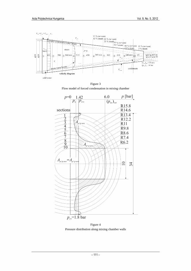
Figure 3
Flow model of forced condensation in mixing chamber
Figure 4
Pressure distribution along mixing chamber walls

M. Bukurov et al. The Efficiency Rate of a Steam-Water Injector
– 112 –
Figure 5
Diagram of Mach number, pressure, velocity, temperature and density for forced condensation

Acta Polytechnica Hungarica Vol. 9, No. 5, 2012
– 113 –
The condensation core’s forming rate is greater under forced condensation
according to Deich and Filipov [5]. The condensate has significantly lower
velocity compared to surrounding steam due to the density difference (w/s
ave=500).
The pressure diagram of steam and mixture contains points of inlet pressure of
steam, the average pressure of mixture (gained from momentum equation) and the
outlet pressure of the mixture – hot water ((pmix)out) (Fig. 1). An abrupt mixture
pressure rise happens in the immediate vicinity of the mixing chamber throat, i.e.
where M=1, according to diagrams given in Fig. 1. and Fig. 5. Experiments [3, 4]
confirm that the pressure change through mixing chamber is stationary, stable and
smooth, without visible and sensed shocks and disturbances. The pressure diagram
(Fig. 4) shows the pressure at the inner side of mixing chamber wall. Each circle
in Fig. 4 corresponds to a certain section (Fig. 3) for which pressure is demanded.
2.1.1 Losses in Mixing Chamber
The efficiency rate of the mixing chamber depends on different kinds of losses:
o loss due to friction on the chamber walls;
o loss due to local drags, oblique and normal shock waves of different origin,
and intermolecular reactions (friction of water, steam and condensate);
o local losses of cold water and steam at the entrance into the mixing
chamber and mixture at the outlet of the mixing chamber.
Friction losses on the inner side of conical wrap of the mixing chamber are
manifested as a pressure drop which is present in whole flow cross section [6].
This downstream pressure drop diminishes outlet pressure in the mixing chamber
throat. Water heat increases due to friction cannot be transformed into pressure
energy because of its low energy potential. Losses due to friction on the chamber
walls are not small compared to the pressure rise along the chamber. If the average
velocity of the rest of the water, near to conical wrap, is vwrest=10 m/s, the pressure
drop through mixing chamber is about p=3000 Pa, which is 0.5 % compared to
the outlet pressure of 6 bar. If the average velocity is 20 m/s, the pressure drop
through the mixing chamber due to friction would be 12,000 Pa, which is,
compared to outlet pressure of 6 bar, 2%. Because of this, it is important to disable
greater velocities of water layer, which is desired to be in constant connection
with walls of mixing chamber.
The internal energy of steam consists of intermolecular and intramolecular
interactions, as well as the energy of random molecular movements, which
depends on temperature. If there are no chemical reactions in the fluid, all changes
in internal energy are due to thermal changes in the fluid, i.e. due to changes in the
kinetic energy of molecular movement and the molecular interaction. Since in the
larger part of mixing chamber there is steam, which can be considered as ideal gas
in that part, its internal energy depends only on the starting and end temperatures.
M. Bukurov et al. The Efficiency Rate of a Steam-Water Injector
– 114 –
Losses due to local changes of stream flow, as well as the occurrence of waves of
different origin, can be considered as irreversible, compared to the pressure drop
decrease which appears no matter where the local resistance takes place. Partial
heat increase, which occurs downstream from these disturbances, cannot diminish
the downstream pressure drop either. Normal stationary shock waves cannot be
transmitted or occur in mixing chamber because of the suppressed effect of the
inlet cold water.
Losses due to friction and mixing of the steam, water and condensate are hard to
estimate, but they can be diminished if continuity in changes of temperature,
steam and velocity of all mixture components are reached. Continuity means
uniform:
o pressure rise of: steam, condensate, water and mixture,
o velocity drop of: steam, condensate and mixture,
o water temperature increase.
Continuity in velocity distribution through a cross section of the mixing chamber
along its whole length, along with maintaining steady water film along chamber
walls, probably presents optimal flow model.
Mechanical efficiency rate of mixing chamber of water-water injector, which
takes into account the friction of the mixing water, as well as the friction of the
water and the walls of the mixing chamber, according to Menegay [7], is 25% for
a relative chamber wall roughness of 0.03. If this value is taken for the steam-
water injector, with assumption that condensate is a drive fluid and cold water is
sucked one, there would appear difference in their kinetic energies at the entrance
and exit of mixing chamber of about 2 kW. The efficiency rate of the mixing
chamber would change by about 0.5%.
Muffling of the supersonic flow, according to its nature, leads to a muffling of
flow anomalies and disturbances. It is known in the transportation of mixtures that
the flow of the mixture calms the whole one-phase fluid flow, which indicates that
both flows are compatible and collectively characteristics of joint model provides
a stable flow.
The reduction of losses in the muffled stream of supersonic mixture increases flow
stability, which can be maintained in moderately non-stationary conditions. If
increased disturbances result in the impossibility of maintaining a stable operation,
these disturbances are source of losses which influence the energy efficiency of
the process.
The estimation of pressure drop due to other mentioned resistances demands much
more information of an experimental nature.
Acta Polytechnica Hungarica Vol. 9, No. 5, 2012
– 115 –
2.2 Supersonic Flow through Steam-Water Injector
The graphically presented distributions of the Mach number (M), pressure (p), and
the velocities of steam and mixture (vs, vmix) are products of laboratory research [3,
4]. Credible pressure lines are those through Laval nozzle and outlet diffuser. The
pressure gradient through mixing chamber is positive, with a steep inflection in
front of the throat of the mixing chamber. The main results of the supersonic flow
through the steam-water injector are presented in Fig. 5.
The discontinuity of pressure due to appearance of shockwaves at the exit of Laval
nozzle, as well as in the mixing chamber, is not registered during the proper
working of the device. Stable work requires a smooth pressure line throughout the
injector, without shockwaves in any part of injector.
The relation between pressure and Mach number could be recognized in already
existing law of compressible flow:
120 11
2
pM
p
(2)
where coefficient (-1)/2 and exponent /(-1) should be exchanged with variable
and independent coefficients (-1)/2=m and /(-1)=n. It is assumed that in the
throat of the mixing chamber prevails almost total pressure, due to the low
velocities in the throat.
Deich and Filipov [5] gave the values for depending on wetness (y). If an
assumption is made that the wetness during forced condensation (Y) is equivalent
to the wetness during free condensation (y), according to eq. (2) total pressures
may be calculated in the throat of mixing chamber.
Calculated values of mixing chamber outlet pressure from eq. (2) partly can be
identified with polytrophic change in the mixing chamber.
The representative parameters of the conducted experimental research are:
o mass flow rate: steam 0.17 kg/ssm , cold water 0.85 kg/swm ,
o dryness rate at: entrance into injector x=1, exit from Laval nozzle x=0.95,
o cross section: in front of injector 40, exit of mixing chamber 10, exit of
diffuser 25,
o velocities: cold water at the entrance of mixing chamber 4.1 m/s, steam at
the entrance of mixing chamber 611 m/s, mixture in the throat of mixing
chamber 13 m/s, mixture at the exit of diffuser 2.1 m/s,
o pressure of: steam in front of Laval nozzle 0 2.6 barsp , cold water at the
entrance into mixing chamber pcw=1.8 bar, mixture (hot water) at the exit of
mixing chamber pmix=6.0 bar, hot water at the exit of diffuser 6.66 bar,

M. Bukurov et al. The Efficiency Rate of a Steam-Water Injector
– 116 –
o temperature of: cold water tcw=12 C, steam at the entrance of injector
ts=127.5 C, mixture at the exit of injector tmix=82 C,
o enthalpy of: steam (total) in front of injector h0=2718 J/kgK, at the entrance
of mixing chamber h=2530 kJ/kgK (0.5 bar, 0.33 kg/m3).
The maximal pressure of hot water is achieved by a rise in outlet downstream
pressure (back pressure), which represents a hot water pipeline pressure drop. The
steam-water injector acts like a volumetric pump since the flow rate is not
dependent upon the variation in outlet pressures.
During experimental research were obtained:
o stable flow for:
- lmc=100 mm and d0=10 mm
o unstable flow with shocks and vibrations and flow rate decrease for:
- lmc=80 mm (for d0=10 mm and d0=8 mm)
- lmc=100 mm and d0=8 mm.
In Fig. 5 is also given the comparative diagram for forced and free condensation
(p, v).
2.3 Effect of Energy Transformation in Mixing Chamber
2.3.1 Water Velocity Distribution in the Mixing Chamber
The velocity distribution of the main water flows in the mixing chamber could
substantially contribute to determining the complex process properties: mixing,
condensation, heat transfer and losses.
Analyses of the flow through the mixing chamber, which are based on present
knowledge about the process, show that basic losses through the mixing chamber
are connected to losses due to inter-phases mixing and friction, and to the friction
of the water (and maybe steam) and the walls of chamber.
Local losses at the entrance of the mixing chamber form a useful initial weak
oblique shock of pressure, which is changed into a continual pressure wave and
culminates at the entrance of the sonic flow region, in front of the chamber throat.
The formation of condensation sources probably influences the pressure wave
shape by changing frequencies, but it is neglected in this case.
It is reasonable to expect that the water heats, mixes with steam and condensates
within optimal energy conditions. It seems that for the rest of water the following
stands:
Acta Polytechnica Hungarica Vol. 9, No. 5, 2012
– 117 –
o heating is homogenous from inlet (12 C) to outlet (82 C) temperature,
which agrees with experimental investigation of Malibashev [9];
o velocity increases from inlet (4.1 m/s) to outlet velocity (13 m/s);
o pressure grows from inlet (pcw=1.8 bar, ps=0.5 bar) to outlet (pmix=6.0 bar).
2.3.2 Energy Transformation
The energy equation, which comprises kinetic, pressure and heat energy, is clearly
presented through injector efficiency analyses.
The efficiency rate of the injector is defined as the ratio between the energy of
outlet hot water and the sum of the energies of the steam and cold water at the
entrance of the mixing chamber. It is accepted that all energies are useful: heat
energy (q [J/kg]), kinetic energy (v2/2 [m
2/s
2]) and pressure energy (p/ [m
2/s
2]).
Kinetic and pressure energy have the same dimensions as heat energy (J/kg or
m2/s
2).
The sum of heat and pressure energies is enthalpy (h). The basic inlet energy is
gained from steam, which is being condensed. Heat energy of about 2200 kJ/kg is
mostly at disposal, and it is latent heat released from the steam during
condensation.
All three kinds of energies are present during the forced mixing of cold water and
steam through the injector, but with huge differences in energy content. Heat and
pressure energy of steam are present in tens and hundreds of kJ, water pressure
energy from 0.1 to 1 kJ/kg, and kinetic energy of steam during supersonic flow
reaches several hundreds of kJ, while kinetic energy of water during standard flow
does not exceed 0.05 kJ.
This means that in order to reach relatively high pressure of water, high heat
energy of steam is not essential, since there is 2200 kJ/kg. (E.g. in order to
increase pressure of 1 kg of water from 0 to 50 bar, 5 kJ is needed.) Water heating
and cooling needs about 4.2 kJ/kgK of heat energy, which is a main energy
requirement in comparison with medium kinetic and pressure energies.
Since flow processes are conducted continuously, each kind of energy (q, p/,
v2/2, [kJ/kg]) is multiplied with mass flow rate [kg/s] and become power in kW.
Therefore, energy efficiency is presented in the relation between exit and inlet
powers (kWout/kWin).
The injector is designed according to its application. The investigated steam-water
injector is used for heating, distant transportation and warm water distribution for
different users. These applications require:
o outlet water which is not too hot (70-80 C) due to diminishing heat losses
along the way;

M. Bukurov et al. The Efficiency Rate of a Steam-Water Injector
– 118 –
o outlet water pressure which is high enough to conquer hydraulic losses (6-8
bar);
o the inlet water temperature should be about 70 C, lower than steam
condensation temperature, in order to successfully conduct condensation
process;
o the inlet water pressure depends on characteristics of the water sources. It
can be atmospheric pressure, but if it is available, water under pressure can
be used as well; in that way, the efficiency rate is increased and a higher
pressure of warm water is more likely;
o inlet steam pressure can be low, which allows for using less quality steam
(pm=1,5-2 bar).
2.4 Efficiency Rate Definitions
Efficiency rates can be defined in different ways, with respect to the basic
postulate that the efficiency rate is a relation between useful (or needed) and
engaged. The terms "useful" and "needed" could be applied to numerous variables:
energy (power, work), bulk (mass, volume), flow surfaces, pressures or their
differences (inlet, outlet), concentrations, granulometric fractions, etc.
The definitions which describe process quality or quality of one of its segment are:
universal efficiency rate, thermodynamic efficiency rate, kinetic energy efficiency
rate, efficiency rate of mixing, etc.
Natural - free condensation of steam (static conditions) is conducted under
constant pressure and almost constant temperature in the whole two-phase area.
Numerous pressure diagrams through cylindrical, and sometimes conical mixing
chambers, accept this law for flow processes too.
Water velocity at the inlet section of the mixing chamber (vcw)mc in and mixture
velocity in the mixing chamber's throat (vmix)mc out are assumed according to the
energy diagram.
Since the difference of latent heat of evaporation , for pressures ranges from 1
to 10 bar is only 3.5%, it can be considered that pressure and temperature do not
influence the heat exchange between water and steam in the two-phase region.
The efficiency rate of the mixing chamber mc is:
2
2 2
1
2
1 1
2 2
mix mix mix
mc out
mc
s s s cw cw cw
L out mc in
h v m
h v m h v m
(3)

Acta Polytechnica Hungarica Vol. 9, No. 5, 2012
– 119 –
The efficiency rate which is used for heat pumps is validated with one of the
following pressure increase efficiency rates ((cw)p, (s)p):
;mix mix
cw sp p
cw s
p p
p p (4)
The commonly used efficiency rate p for small injection coefficients ucw p<3
(cw p cw su m m ) is given as following:
mix s
p
s cw
p p
p p
(5)
where:
pmix, pcw and ps are the pressures of mixture, water and steam Pa.
For higher injection coefficients the next relation is valid:
mix cw
p
s cw
p p
p p
(6)
For both relations, the denominator is the same and can be considered as engaged
pressure.
2.5 Efficiency Rate of Laval Nozzle l
In the ideal case, the flow through the nozzle and diffuser is isentropic. But in the
actual case, friction exists and affects in following ways:
o reduces the enthalpy drop and the final velocity of steam
o increases the final dryness fraction and specific volume of the fluid
o decreases the mass flow rate.
The efficiency of the nozzle depends upon:
o the material it is made of and its smoothness,
o the size, shape and angle of the nozzle divergence,
o the nature of fluid flowing and its state,
o the fluid velocity and the turbulence in nozzle flow.
The efficiency rate of the Laval nozzle for superheated and wet steam flow is
determined by many experimental results with satisfying accuracy. So far, the
transformation of friction through the Laval nozzle into thermal energy is not
explained enough. The nature of energy loss in the case of a normal shockwave in
the diffuser of the Laval nozzle can be explained. The inlet parameters of the
steam in the mixing chamber can be determined if the efficiency rate of the Laval
nozzle is known.

M. Bukurov et al. The Efficiency Rate of a Steam-Water Injector
– 120 –
The efficiency rate of the Laval nozzle is based on knowing the investigated
features of the convergent nozzle, whose efficiency rate is dominant in the
equation for L.
The complete diagram of the efficiency rate of Laval nozzle L is shown in Fig. 6
with three curves: real nozzle (with friction) L, theoretical Lth and with post
expansion Le.
Figure 6
Efficiency rates of Laval nozzles for smooth surfaces and shock less processes ( bar kg ss sp m ;
hL=hLin-hLout) according to Hess [4]
The efficiency rates’ theoretical curves of the Laval nozzle with post expansion
Le=f(hL) are parallel and with one maximal value. Only experiments can show the
magnitude of post expansion in order to achieve the maximal efficiency rate for
the given Laval nozzle.
Each of the curves is given for the certain value of the Reynolds number or
characteristics of flow s sm p . Divergent section is with central angle of 10-20. In
this range of angles, the change in efficiency rate is within tolerable limits. During
the flow of steam through the Laval nozzle, the boundary layer is turbulent.
In the representative case, where 0.17 kg/ssm , p0s =2.6 bar, h0=2718 kJ/kg,
(h0)L out=2530 kJ/kg, hL=188 kJ/kg and 0 0,442s sm p ;

Acta Polytechnica Hungarica Vol. 9, No. 5, 2012
– 121 –
o the efficiency rate of the Laval for all kind of energies is L=0.98.
o the power loss through Laval nozzle is 0.171880.02=0.64 kW.
o The steam power at the outlet of the Laval nozzle is 2718·0.17-
0.64=461.42 kW, where
kinetic power is ((6112/2)·0.17)/1000=31.73 kW
enthalpy power (thermal and pressure power) is
2530.0.17=430.1 kW.
The outlet pressure should not be too low compared to the nozzle throat pressure,
in order to eliminate the possibility of a shock wave forming in the supersonic
nozzle section, which does not contribute to the proper operation of the injector.
The outlet pressure from the Laval nozzle should be about 0.4-0.5 bar (absolute
pressure), which allows for the usage of low-pressure steam in suction of cold
water on atmospheric pressure.
2.6 Overall Efficiency Rate of Laval and Cold Water Nozzle
According to [10], the efficiency rate for designed cold water nozzle for lost
kinetic energy (without thermal energy) is estimated as cw=0.90.
For outlet water velocity of a nozzle of 4.1 m/s:
o the intake kinetic power of the cold water is (4.12/2)·0.85=7.144 kW,
o the lost kinetic power through the cold water nozzle is 7.144·0.1=0.714 kW
o the kinetic power at the inlet of the mixing chamber is 7.14·0.90=6.43 kW
o the efficiency rate of the cold water nozzle, which refers to all kind of
energies, is (42.738+7.14·0.9+0.153)/(42.738+7.144+0.153)
=49.317/50.035=0.986.
The power loss through the Laval nozzle is 0.64 kW, and for the cold water nozzle
it is 0.714 kW.
The total steam power at the entrance of the injector (462.06 kW), and cold water
(50.035 kW) is 512.09 kW.
The total power of steam and cold water at the inlet of the mixing chamber with
embraced losses is:
512.09-0.714-0.64=510.74 kW.
Overall efficiency rate of Laval and cold water nozzle is
L+cwnozz=510.74/512.09=0.99.

M. Bukurov et al. The Efficiency Rate of a Steam-Water Injector
– 122 –
2.7 Efficiency Rate of Outlet Diffusor
The efficiency rate of the outlet diffuser is discussed according to several
assumptions:
o The diffuser is filled with an homogeneous stream of hot water without
steam bubbles;
o The heat losses are neglected;
o Condensation is completely finished in the throat of mixing chamber.
With assumption that velocity profile uniformly decreases through diffuser cross
section, the efficiency rate (without thermal energy) – cold dc is:
2
2 22
11
122
out in out ind d
dc
inin out d in dout d
p p p p
Av vv
A
(7)
The outlet diffuser is designed with diameters ratio 1:3 (10:30) and half angle
=6; for which is, according to [10] efficiency rate dc=0.95. The efficiency rate
of the outlet diffuser of 0.95 refers to the lost kinetic energy of 5%. For dc=0.95
and an inlet velocity of 13 m/s and an outlet velocity of 2.1 m/s, the lost power is
2 2 1 / 2 0,0042 kWlost in out mix dcP v v m . From this it follows that the
efficiency rate of outlet diffuser is d=1.
According to equation (7), which is in accordance with experimental results, the
absolute pressure of the hot water at the outlet of the diffuser is:
(pd)out=6.66 bar
2.8 Efficiency Rates of Mixing Chamber (Mc) and Injector
(Inj)
According to known characteristics of hot water at the outlet of the diffuser, as
well as the diffuser's efficiency rate, the parameters in the throat of the mixing
chamber are: pmc out=6.0 bar, vmc out=13 m/s, tmc out=82 C, and 1.02 kg/smcoutm .
Steam is completely condensed at the outlet of the mixing chamber.
Hot water power at the outlet of the mixing chamber is:
(82·4.19+132·0.5+0.6)·1.02 = 437.25 kW.
Power at the inlet of the mixing chamber is 510.74 kW.
The efficiency rate of the mixing chamber is
437.25 510.74 0.856mc .

Acta Polytechnica Hungarica Vol. 9, No. 5, 2012
– 123 –
The efficiency of the whole injector is given by eq. (1):
0.99 0.856 1.0 0.847inj L cwnozz mc d .
The small difference in the efficiency rates of the mixing chamber and the whole
injector is a result of the small powers that are spent in: the Laval nozzle, the cold
water nozzle and the outlet diffuser. The efficiency rate of the Laval nozzle is the
relation between the total energies at its outlet and inlet section, while in the case
of the cold water nozzle and the outlet diffuser, losses are connected only to the
change of kinetic energy, which is several times smaller than total power that is
being transmitted through them.
The mixing chamber efficiency rate cannot be determined without knowing the
flow-phases and energy transformation through them. Without any doubt, part of
the pressure increase is fulfilled due to the kinetic energy of the steam which
enters into mixing chamber.
The basic question without proper answer is whether it is possible to control and
manage the process of complex changes through the mixing chamber or whether
the process depends, to the greatest extent, on the thermo dynamical nature of the
free condensation of steam. No matter the answer to this unanswered question, the
efficiency rate of the mixing chamber can be determined for some assumed cases.
The flow through injector is characterized by complex processes of steam,
condensate, cold and hot water inter reactions.
Conclusions
In addition to the known and frequent transformation of thermal into kinetic
energy, the transformation of steam thermal energy into pressure energy of a
mixture in a supersonic stream, which is possible by condensation, using latent
heat, was also confirmed.
During experimental investigation, the stable work of a steam-water injector
(without pulsations and shocks) was established. In order to reach stable work, it
is necessary that the flow process through all parts of the injector is in balance.
This means: The sound velocity of steam in the throat of Laval nozzle and
supersonic velocity are reached at its outlet; and supersonic compressible flow
prevails through the mixing chamber and subsonic flow of hot water prevails
through the outlet diffuser of steam-water injector.
The flow through the Laval nozzle depends on the geometry of the nozzle and the
inlet state of the steam. The parameters at the outlet section of the Laval nozzle
are dictated by the steam. The inlet cold water pressure can vary depending on the
water source.
During the proper operation of the steam-water injector, water does not evaporate
in the mixing chamber; otherwise it would be noticed by unsteady effects. The
steady range of the steam-water injector operation depends on a limited coefficient
of injection.

M. Bukurov et al. The Efficiency Rate of a Steam-Water Injector
– 124 –
The inlet section of the mixing chamber is filled with cold water (orifice with
small thickness), i.e. mixture of steam and cold water (Y=0.5). In the greater part
of mixing chamber is a two phased region, which is completely condensed in the
vicinity of the mixing chamber throat. Supersonic flow exists in the whole mixing
chamber; at the beginning, the average velocities of steam are high, and in the
vicinity of the throat, the velocity of the mixture are considerably lower. At the
entrance of mixing chamber, the Mach number is greater than unity, M>1, because
of the expansion of the steam through the Laval nozzle, and in the environment of
the throat M≈1, because of very low sound velocities in the very wet steam.
In the throat of the mixing chamber, changes in the flow parameters without
shocks are with high gradients and pretty independent of the size and changes of
the Mach number through the mixing chamber.
In this paper is presented the recommended velocity distribution of the active and
inert components of cold water. It is impossible to determine losses in the mixing
chamber without knowing the velocity distribution of the water that is actively and
directly mixed with steam (vwmix) and of the water which flows further on and
continuously, partially and actively mixes with steam (vwrest). The efficiency rate
of the injector device shows that major losses happen in the mixing chamber. The
losses are the immediate consequences of considerable friction between the steam,
condensate, and active and rest (inert) water. It seems that the mixing chamber
walls cause the most significant loss, which means that the better velocity profile
is the one with higher gradient in the zone of intensive steam and water mixing.
Forced condensation, compared to free condensation, increases the mixing
chamber outlet pressure of hot water. The supersonic mixing chamber is actually a
diffuser through which pressure rises downstream. Pressure rise during supersonic
flow has the same nature as flow through diffuser in subsonic flow.
The average pressure in the mixing chamber, gained from momentum equation,
enables a more accurate determination of the pressure distribution through the
mixing chamber. In this way the determined average pressure agrees with the
actual pressure.
Acknowledgement
This work was supported by Serbian Ministry of Science in the framework of the
project 31058.
Appendix
Nomenclature
A [cm2] cross section area
c [m/s] sound velocity
d [m] diameter
h [J/kg] enthalpy
l [m] length

Acta Polytechnica Hungarica Vol. 9, No. 5, 2012
– 125 –
M [-] Mach number
m [-] coefficient
m [kg/s] mass flow rate
n [-] coefficient
P [W] power
p [Pa] pressure
Q [m3/s] flow rate
q [J/kg] heat energy
T [K] temperature
t [C] temperature
u [-] injection coefficient
V [m3] volume
v [m/s] velocity
X [%] dryness during forced condensation
x [%] dryness during free condensation
Y [%] wetness during forced condensation
y [%] wetness during free condensation
α [] half angle of diffuser
[-] efficiency rate
[-] isentropic exponent
[J/kg] latent heat
[kg/m3] density
Subscripts
0 total
a atmospheric
ave average
c cold
con condensed
cw cold water
d diffuser
hw hot water
i section number (i=1,2,...10)
in inlet
inj injector
L Laval nozzle
Le Laval nozzle with post expansion
l losses
lost lost
m manometric,
mc mixing chamber
mix mixture
nozz nozzle
out outlet
s steam

M. Bukurov et al. The Efficiency Rate of a Steam-Water Injector
– 126 –
th throat
w water
wm water for mixing
wrest the rest of water
References
[1] H. El-Dessouky, H. Ettouney, I. Alatiqi, G. Al-Nuwaibit, Evaluation of
Steam Jet Ejectors, Chemical Engineering and Processing 41, pp. 551-561,
2002
[2] M. Trela, R. Kwidzinski, D. Butrymowicz, J. Karwacki, Energy Analysis
of Two-Phase Steam–Water Injector, Applied Thermal Engineering 30, pp.
340-346, 2010
[3] M. Bukurov, Research on Supersonic Steam-Water Injectors
Characteristics (in Serbian) Doctor Thesis, Faculty of Technical Sciences,
Novi Sad, Serbia, 2004
[4] M. Bukurov, S. Tasin, S. Bikić, Modified Diagram for Steam-Water
Injector Mixing Chamber, Annals of the Faculty of Engineering Hunedoara
- Journal of Engineering, Fascicule 4, No. VII, pp. 75-82, ISSN 1584-2665,
2009
[5] M. E. Deich, G. A. Filipov, Gas Dynamics of Two-Phase Flow (in
Russian) Energy, Moscow, Russia, 1968
[6] Y. Yamazaki, T. Nakayama, T. Narabayashi, H. Kobayashi, T. Shakouchi,
Effect of Surface Roughness on Jet Pump Performance, JSME International
Journal, Series B, Vol. 49, No. 4, pp. 928-932, 2006 [7] P. Menegay, A
Computational Model for Two-Phase Flow, Dissertation, State University,
Virginia, 1997
[8] F. Hess, The Efficiency of Motive Nozzles in Steam-Jet Pumps,
Proceedings of 1st Symposium on Jet Pumps and Ejectors and Gas Lift
Techniques, D1-11, BHRA, UK, 1973
[9] S. K. Malibashev, Experimental Investigation of Transparent Models of
Steam-Water Injector with a Convergent Nozzle, Atomic Energy, Vol. 90,
No. 6, pp. 469-474, 2001
[10] Fluid Flow Data Book, General Electric Company Corporate Research and
Development, NY, 1973