the electrical installations and electrical equipment pertaining to
TRANSCRIPT
DEPARTMENT OF PUBLIC WORKS
STANDARD SPECIFICATION
FOR ELECTRICAL INSTALLATIONS
AND ELECTRICAL EQUIPMENT
PERTAINING TO
MECHANICAL SERVICES
PRETORIA:OFFICE OF THE DIRECTOR:ENGINEERING SERVICESISSUE 1X aDECEMBER 1999
2
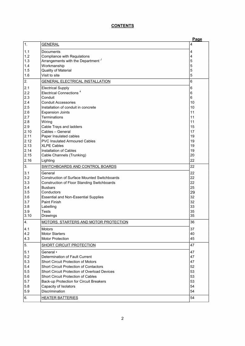
CONTENTS
Page1. GENERAL 4
1.1 Documents 41.2 Compliance with Regulations 41.3 Arrangements with the Department J 51.4 Workmanship 51.5 Quality of Material 51.6 Visit to site 52. GENERAL ELECTRICAL INSTALLATION 6
2.1 Electrical Supply 62.2 Electrical Connections 4 62.3 Conduit 62.4 Conduit Accessories 102.5 Installation of conduit in concrete 102.6 Expansion Joints 112.7 Terminations 112.8 Wiring 112.9 Cable Trays and ladders 152.10 Cables – General 172.11 Paper Insulated cables 192.12 PVC Insulated Armoured Cables 192.13 XLPE Cables 192.14 Installation of Cables 192.15 Cable Channels (Trunking) 202.16 Lighting 223. SWITCHBOARDS AND CONTROL BOARDS 22
3.1 General 223.2 Construction of Surface Mounted Switchboards 223.3 Construction of Floor Standing Switchboards 223.4 Busbars 253.5 Conductors 293.6 Essential and Non-Essential Supplies 323.7 Paint Finish 323.8 Labelling 333.9 Tests 353.10 Drawings 35
4. MOTORS. STARTERS AND MOTOR PROTECTION 36
4.1 Motors 374.2 Motor Starters 404.3 Motor Protection 45
5. SHORT CIRCUIT PROTECTION 47
5.1 General • 475.2 Determination of Fault Current 475.3 Short Circuit Protection of Motors 475.4 Short Circuit Protection of Contactors 525.5 Short Circuit Protection of Overload Devices 535.6 Short Circuit Protection of Cables 535.7 Back-up Protection for Circuit Breakers 535.8 Capacity of Isolators 545.9 Discrimination 54
6. HEATER BATTERIES 54

3
7. SWITCHGEAR 55
7.1 Metal Clad Air Circuit Breaker, Withdrawable Type 567.2 Moulded Case Circuit Breaker 567.3 Earth Leakage Relays 577.4 On-load. Fault-Making Switches 587.5 Rotary switches 587.6 Microgap Switches 587.7 Combination Fuse switch units 597.8 Fuses and Fuse Holders 597.9 Contactors 607.10 Indoor Lightning Arresters 61
8. CONTROL EQUIPMENT 61
8.1 Voltmeter Selector Switch ' 628.2 Voltmeter Fuses 628.3 Ammeter Selector Switches 628.4 Control Selector Switches 628.5 Push Buttons 628.6 Relays 638.7 Time Switches 638.8 Sequence Time Switches 64
9. INSTRUMENTATION 64
9.1 General 649.2 Voltmeters 659.3 Ammeters 669.4 Maximum Demand Ammeters 669.5 Kilowatt-hour Meters 679.6 Current Transformers 679.7 Hour meters 679.8 Indicator Lights 67
APPENDIX A : DUTY CATEGORY FOR CONTACTORS 68
APPENDIX B : CLASS OF PROTECTION 69
DRAWINGS:
The following drawings form part of this Specification:ME 700A/20: Example of small control boards
ME 700A/21: Example of large control boards
ME 700A/22: Circuit Diagram

4
1. GENERAL
1.1 Documents
1.1.1 This Specification covers the general requirements regarding material, equipment, installation, testingand commissioning of the Electrical Installation and Equipment for Mechanical Systems and shall beread in conjunction with the Conditions of Tender. Conditions of Contract and the Detailed TechnicalRequirements for the specific installation.
1.1.2 "Documents" shall mean the complete set of documents consisting of the Conditions of Tender,Conditions of Contract, Detailed-Technical Requirements and this Specification, including allAppendices and Questionnaires.
1.1.3 The complete Installation shall comply with the requirements of this Specification. Should anydifferences or contradictions exist between this Specification and the Detailed TechnicalRequirements for the specific installation, then the latter shall take precedence.
1.2 Compliance with Regulations
1.2.1 The Installation shall be erected and carried out in compliance with:
The Code of Practice for the Wiring of Premises, SABS 0142, as amended.
The Occupational Health and Safety Act. 1993 (Act 85 of 1993), as amended, or any other substitutingor augmenting legislation which may be enacted before tender closure.
The Mines and Works Regulations, Government Notice No. R1609 of the 28th September. 1962 asamended.
The Local Government Ordinance 1939 (Ordinance 17 of 1939) as amended and the local MunicipalBy-laws and Regulations as well as the Regulations of the local Supply Authority and any specialrequirements of the local supply authority.
The Fire Brigade services Act 1993 Act 99 of 1987 as amended,
The National Building Regulations and Building Standards Act, 1977 (Act 103 of 1977) as amended,as well as any incorporated Standards.
The Post Office Act 1958 (Act 44 of 1958) as amended.
The Electricity Act 1984 Act 41 of 1984 and
The Regulations of the Local Gas Board where applicable.
1.2.2 The Contractor shall appoint a Responsible Person / Competent Person in terms of the requirementsof the Occupational Health and Safety Act to take all responsibility for the compliance with the Act ofany of his staff, labour and subcontractors and all installations and equipment operated and plantinstalled by the Contractor. The Contractor (or the person authorised to tender) shall, if such a Personis not appointed, personally take these responsibilities upon himself. The Contractor shall indemnifythe Department and any of its employees against any culpability arising from any action or negligenceon his behalf in this regard pertaining to the site of the Contract and its content or improvements ofany nature.
1.2.3 In addition, the Contractor shall indemnify the Department against all losses, costs or expenditures aswell as culpability which may arise as a result of the Contractor's negligence in complying with therequirements of the regulations enumerated above.
1.2.4 It shall be assumed that the Contractor is fully conversant with the above mentioned requirements.Should any requirement, by-law or regulation, which contradicts the requirements of this Document,apply or become applicable during erection of the Installation, such requirement, by-law or regulationshall overrule the requirements of this Document and the Contractor shall immediately inform theDepartment's Representative of such a contradiction. Under no circumstances shall the Contractorcarry out any variations to the Installation in terms of such contradiction without obtaining the written

5
permission to do so from the Department.
1.3 Arrangements with the Department
1.3.1 It shall be the responsibility of the Contractor to make the necessary arrangements with theDepartment for the electrical supply, and to supply the labour, equipment and means to inspect, test,commission and hand over the Installation.
1.3.2 The Contractor shall supply and install all notices and warning signs that are required by theappropriate laws or regulations and/or by these Documents.
1.3.3 In the case of an existing facility, the Contractor shall make arrangements with the user of the facilitywell in advance for any power cuts or disruption of any other services during the construction period.Where any power spikes or disturbances may affect sensitive equipment, the Contractor shall makethe fact known to the user beforehand and the Contractor shall take full responsibility to ensure thatsuch equipment does not suffer damage due to the Contractor's activities on site.
1.4 Workmanship
1.4.1 The Contractor shall employ only competent artisans to carry out the Installation on site. Traineesmay be used under strict supervision and in the performance only of tasks, which do not require fullyqualified artisans for their completion.
1.4.2 The Contract shall be executed with the best workmanship in a workmanlike manner and to thesatisfaction of the Department's Representative. Should any material or workmanship not be to thesatisfaction of the Department, it shall be rectified at the cost of the Contractor and all rejectedmaterial shall be removed from site.
1.4.3 The Contractor shall be responsible for the correct and complete erection of the Installation.Inspections by the Department's Representative will not release the Contractor from thisresponsibility. All installations shall be complete and functional in every respect as indicated in thescope of contract and the technical specification pertaining to the relevant contract.
1.5 Quality of Material
1.5.1 Only material of the highest quality, equal to or exceeding the specified properties and qualitiescontained in the tender documentation shall be used and shall be subject to the approval of theDepartment.
1.5.2 All material, where applicable, shall conform in respect of quality, manufacture, tests andperformance, with the requirements of the South African Bureau of Standards or where no suchstandards exist, conform with the appropriate current I EC specification or the Specification of theBritish Standards Institution. Material manufactured in South Africa shall as far as possible be used.
1.5.3 Imported materials shall comply with the requirements of the appropriate SABS, IEC. BS orinternationally accepted published comparable standard specification although these materials neednot necessarily bear the SABS mark.
1.5.4 All materials shall be suitable for the conditions on site. These conditions shall include weatherconditions as well as prevailing conditions during installation and subsequent use. Should thematerials or components not be suitable for use under temporary site conditions, the Contractor shallprovide at his own cost suitable protection until these unfavourable site conditions cease to exist.
1.6 Visit to Site
Tenderers shall acquaint themselves with the local weather conditions and local site conditions suchas access to the site, size and type of site, type of soil, supply of labour, workshop space, storagespace, transport, loading and unloading facilities, scaffolding, tackles and tools required for theerection of the Installation. Additional claims by the Contractor, which may arise from ignorance ofsite conditions, will not be considered and tenderers are advised to visit and inspect the site beforesubmitting their tender price.
2. GENERAL ELECTRICAL INSTALLATION
6
2.1 Electrical Supply
Unless otherwise specified the Department of Public Works will provide a 3 phase. 4 wire electricalsupply (cable end only) to feed the Main Control Panel in each Plant Room in the position shown onthe drawings. The connecting of the incoming supply cable to the Control Panel(s) and the supply,installation and termination of all other cables, e.g. between the Control Panel and the equipment,various elements of the installations or separate parts of systems is the responsibility of theMechanical Contractor. The Department of Public Works will also provide room lighting and a single-phase 15 A socket in each plant room. The room lighting and 15 A socket will not be available duringinstallation and the Mechanical Contractor shall make provision in his price for the provision oftemporary power and lighting during installation.
2.2 Electrical Connections
The wiring of plant and all accessories shall be installed by the Contractor using solid drawn or butt-welded conduit with PVC insulated stranded conductors in accordance with SABS 1507, or multi-corePVC/SWA/PVC cables using approved waterproofed glands, whichever method is specified. Themain runs of conduits or cables shall be carried along the ceiling (either centrally or as may best fitthe plant room layout) and be distributed vertically to the required points. The proposed location ofconduits or cables shall be pointed out to and receive the approval of the Department'sRepresentative before commencement of the work.
2.3 Conduit
2.3.1 General
2.3.1.1 The following types of conduit are covered in this section of the specification:
(a) Screwed metallic conduit, both black-enamelled and galvanised(b) Plain-end metallic conduit, both black-enamelled and galvanised(c) Non-metallic conduit(d) Flexible conduit
2.3.1.2 Other Services
Conduits may not be installed closer than 150mm to pipes containing gas, steam, hot water, chilledwater or other materials that may damage the conduits. Conduits shall not be mounted directly belowthese services unless prior written approval has been obtained from the Department. Conduits maynot touch pipes of other service installations in order to prevent electrolytic corrosion. Where this isunavoidable, cathodic protection shall be provided.
2.3.1.3 Tenderers shall ensure that general approval of the proposed conduit system to be used is obtainedfrom the local electricity Supply Authority prior to the submission of their tender. Under nocircumstances will consideration be given by the Department to any claim submitted by theContractor arising out of a lack of knowledge of the Supply Authority's requirements.
2.3.1.4 Conduit and accessories used for flameproof installations and for the suspension of luminaires aswell as all load-bearing conduit shall in all instances be of the screwed type.
2.3.1.5 Draw wires: Galvanised steel draw wires shall be installed in all unwired conduits (e.g. conduit forfuture extensions). Permanently marked metal labels shall be provided at each end of the draw wirefor identification of the conduit run.
2.3.2 Metallic conduit
2.3.2.1 All metal conduit shall comply with SABS 1065. Galvanised conduit shall be hot-dip galvanised inaccordance with SABS 763.
2.3.2.2 Galvanised Conduit
Galvanised conduit and accessories shall be used in the following circumstances:
7
In damp areas.
In areas exposed to the weather.
In concrete floors and ceilings.
For all installations within 50 kilometres of the coast.
In air-conditioning and ventilation plenum chambers.
For surface mounted conduit installations in kitchens and boiler rooms.
2.3.2.3 Installation
While erection of the installation is in progress, care shall be taken that debris does not enter theconduits. All open ends shall be closed by means of solid plugs that are screwed into the couplings(PVC plugs are not acceptable). The conduits shall be swabbed before the conductors are pulled in.The swab may not be pulled through the conduit by connecting it to the conductors. All conduits shallbe inspected before installation and any defective materials removed from the site. All conduit endsshall be reamed, threaded and tightly screwed home. After installation, threads shall not be visibleexcept in the case of running joints where the visible thread shall be kept to an absolute minimumand shall be painted with red lead immediately after installation. In damp areas, in all areas within 50kilometres of the coast and in cases where the installation will be exposed to the weather for longperiods, all connections in the conduit installation shall be painted with red lead and all vice marksand other damage to the galvanising, paint or other protective coating on the conduit or accessoriesshall be repaired immediately after installation. (Refer to par. 2.5. for conduit installed in concrete.)
As an alternative to the screwed conduit type of installation, plain-ended metallic unscrewed conduitsystems will also be acceptable to the Department. The use of these alternative systems is, however,subject to the following conditions:
The unscrewed conduit shall be manufactured of mild steel having a minimum thickness of 0,9 mmand shall be in accordance with SABS 1065. Conduit manufactured of lighter gauge material, i.e. 0,7mm will not be permitted.
Bending and setting of unscrewed conduit shall be carried out with special benders and apparatusmanufactured for the purpose. Damage to the conduit resulting from the use of incorrect bendingapparatus or methods must, on indication by the Department's representative, be completelyremoved and rectified and any wiring already drawn into such damaged conduits shall also becompletely renewed at the Contractor's expense.
All prefabricated conduit couplings and bends shall be galvanised.
The conduit and wiring shall further be installed strictly as described in the rest of par. 2.3 and in par.2.8.
Continuity: Mechanical and electrical continuity shall be maintained throughout the conduitinstallation.
Fixing: Conduit shall be firmly fixed by means of saddles with a maximum spacing of 2 m and at adistance of 150 mm before and after each 90° bend. Alternatively, conduits may be fixed to metalracks or be carried in metal dueling (channels).
Bends: Only two 90° bends or equivalent angular displacement will be allowed between draw boxesand/or outlets. All bends shall be made cold without any degree of flattening of the conduit. The innerradius of a bend shall be at least three times the outside diameter of the conduit.
Offsets: Conduit routes shall be carefully planned to avoid crossovers as far as possible. Where,however, crossovers are unavoidable, offsets shall be made in one of the conduits only and shall besymmetrical and as short as possible. Where offsets are made for crossovers or for terminatingconduits on equipment, the conduit shall be saddled at the beginning of the offset.
2.3.3 Non-metallic conduit (May only be used within 50km from coast)

8
2.3.3.1 Installation Conditions
Where specified for a particular service, non-metallic conduit may be installed under the followingconditions:
All non-metallic conduit shall comply fully with SABS 950 and shall be installed in accordance withAppendix C of the same specification as well as SABS 0142.
Insulated heat-resistant boxes shall be used for outlets of totally enclosed luminaires and otherfittings where excessive temperatures are likely to occur.
Luminaires and other fittings shall not be supported by non-metallic conduit or conduit boxes. Thesefittings shall be secured to the surrounding structure in a way that is acceptable to the Department.Refer to the Department's standard specification for "INSTALLATION OF LUMINAIRES", Section B9.
The conduit shall be supported and fixed with saddles with a maximum spacing of 500mm, even inroof spaces. (Refer to SABS 0142.) The Contractor shall supply and install all additional supportingtimbers required.
It shall be possible to rewire the completed installation in the future without undue difficulty.
2.3.3.2 Non-metallic conduit and fittings shall not be used under the following conditions:
Outside a building (unless protected, or sheltered under eaves).
For mechanical load bearing.
Where they may be subjected to temperatures below -10°C or above 70°C for prolonged periods.
As primary electrical insulation.
In areas where they may be subject to mechanical damage.
For applications other than those for which they are designed.
In concrete slab unless specified to the contrary.
2.3.3.3 Painting of Conduits
Exposed conduit may be painted with normal oil or PVA paints, but care must be taken to ensure thatthe paint used does not contain any component that will soften or have any other detrimental effecton the materials from which the conduit and fittings are manufactured.
2.3.3.4 Connecting of Conduit to Metal Equipment/Components
When any part of a non-metallic conduit system has to be connected to metal equipment orcomponents (e.g. switchboard, surface socket-outlet or switch box, existing metallic conduit system,etc.) fittings and joints manufactured specifically for this purpose must be used. Non-metallic conduitmust not be threaded to fit metallic connectors. Earth continuity shall be maintained between theconduit installation and metal parts, which are being interconnected via non-metallic conduit at all,times.
2.3.3.5 Bends
In conduit of nominal size not exceeding 25 mm, bends may be made in accordance with par. 4.5. Inall other cases bends must be achieved by the use of accessories that are introduced into the conduitrun. Bends shall comply with SABS 0142.
2.3.3.6 Bending
Conduit of nominal size up to and including 25mm may be cold bent by hand provided that the radiusof the bend is greater than six times the nominal size of the conduit, and that the external angle of thebend does not exceed 90°. The procedure (which involves the use of a bending spring) should be as
9
follows
Determine the angle through which the conduit is to be bent. Warm the cold conduit over the length
to be bent by rubbing with hands.
Select a bending spring which matches the conduit size and insert in to the conduit at the point wherethe bend is required.
Bend the conduit slowly with one motion (either with the hands alone approximately 1 m apart, oracross the knee) to double the required angle, release the conduit and, when its position is stable,withdraw the bending spring (turning it in an anti-clockwise direction to reduce its diameter) andgently correct the angle.
Install and secure the conduit immediately following bending.
2.3.3.7 Adhesive Joints
All adhesive joints must be made in a clean dry area. The surfaces of all components to be bondedmust be dry and clean.
The insertion depth should be marked on the conduit end and the adhesive applied (by means of asoft clean brush) as quickly as possible to the surfaces to be bonded by brushing lengthwise alongthe conduit, ensuring that a thin coating of uniform thickness is formed. The joint must be madeimmediately after the application of the adhesive by pushing the prepared parts squarely togetherwith a twisting motion to the full insertion depth. Care must be taken to avoid squeezing adhesive intothe cableway and all excess adhesive must be wiped off.
NOTE: Solvent adhesives contain highly volatile liquids and their containers should not be left open.
2.3.3.8 Cutting:
A fine-tooth hacksaw should be used to cut conduit to the required length. Each cut end should besquare and free from swarf, burrs and loose material. When determining the length of conduit to becut, allowance must be made for the length of couplings or accessories attached to the conduit.Incorrect determination will cause bulging of the conduit or insufficient joint length, which will not beaccepted.
2.3.4 Flexible Conduit
2.3.4.1 In substations where equipment is moved during normal operation, or in the case of connection tomotors or other vibrating equipment, or connections to thermostats and sensors on equipment andas otherwise specified, flexible conduit shall be used for the final connection to the equipment.
2.3.4.2 The length of flexible conduit shall be as short as possible and shall not be longer than 600 mmunless previously applied for and approved by the Representative of the Department.
2.3.4.3 Flexible conduit shall be connected to the rest of the installation via a draw box. Where the flexibleconduit can be rewired without difficulty, connection can be made to a conduit end if there is a drawbox within 2 m of the connection.
2.3.4.4 Flexible conduit shall be of galvanised steel construction and in damp areas of the plastic sheathedgalvanised steel type. Connectors for coupling onto the flexible tubing shall be of the gland or screw-in type, manufactured either of brass or cadmium or zinc plated mild steel. It shall be mounted insuch a fashion as to prevent ingress of dust and moisture.
2.3.4.5 Flexible conduit may alternatively be of electro-plated galvanised steel construction protectivelycovered with high quality PVC.
2.3.4.6 Flexible conduit connections shall be provided with an internal or external earth wire connection asrequired by the Local Supply Authority. Where no specific requirement of the Local Supply Authorityexists, the earth wire shall be run internally.

10
2.4 Conduit Accessories
Galvanised conduit accessories shall be used in all areas as described in par. 2.3.2.2 and thegalvanising shall be repaired immediately after installation as described in 2.3.2.3.
All outlet boxes and draw boxes shall be of the inspection type. Inspection type couplings, bends andT-pieces will not be allowed without the written approval of the Department's Representative.
All accessories at outlets such as connections to equipment, starters, wall sockets, switches, lights,etc. shall be accurately located in the positions shown on the drawings or as otherwise required bythe Installation. It is the Contractor's responsibility to determine the final floor, roof or ceiling heightsand to install all accessories straight and level and at the correct height.
Under no circumstances shall draw boxes be placed in positions where access, after the completionof the Installation, is impossible. All draw boxes shall be pointed out to the Department'sRepresentative after installation and shall be shown on the "as built" drawings.
Where more than one socket outlet is connected to the same circuit, a loop-in system shall be used.Where power skirting or power trunking is used, conduits may be installed directly from the trunkingto the outlets on condition that the wiring can still be looped between the various socket outlets. Alldraw boxes or outlet boxes for future connections shall have cover plates fitted.
2.5 Installation of conduit in concrete
Where it is required that the conduit installation be cast into the concrete, the following shall apply:
2.5.1 Conduits of wall thickness less than 1,2 mm shall not be used.
2.5.2 Deep type conduit boxes in slabs and rear entry concrete boxes in hollow block constructions shall beused.
2.5.3 Elbows for conduits of 32 mm and smaller and sharp bends will not be allowed.
2.5.4 Conduit shall be installed as close to the neutral axis of the beam, slab or column as possible.
2.5.5 Conduit shall be fixed to the reinforcing steel or shuttering to prevent movement towards the surfaceduring the casting of concrete.
2.5.6 All outlet and draw boxes shall be firmly fixed to the shuttering by means of a long bolt and nutthrough holes that have been drilled in the back of the box and the shuttering. Wire fixings will not beaccepted in off-shutter concrete finishes. All boxes shall be tightly packed with wet paper beforefixing to the shuttering.
2.5.7 Conduits may not be installed in floor slabs of boiler rooms, laundries and other damp areas. Laundryequipment shall be fed by means of multicore PVC insulated cables installed on galvanised cabletrays or in galvanised metal trunking. The conduits to all socket outlets and single and three-phaseconnections in damp areas, shall be installed from the top downwards to avoid moisture collecting inthe conduits.
2.5.8 The upper surface of conduits installed in screeds shall be at least 20 mm below the final surface. Aminimum distance of twice the outside diameter of the conduit shall be allowed between adjacentconduits in screeds. Conduits shall be fixed to the slab at intervals not exceeding 2 m before the slabis screeded.
2.5.9 Within two days of removal of the shuttering, all draw boxes shall be inspected and cleaned and drawwires shall be installed. Should there be draw boxes or conduits that are blocked or have beenomitted, alternative arrangements shall immediately be made by the Contractor, subject to thesealternative methods/routes being to the approval of the Department's Representative.
2.6 Expansion Joints
2.6.1 Where a conduit crosses an expansion joint, an approved type of draw box shall be provided.
2.6.2 The draw box shall be installed adjacent to the expansion joint. A conduit sleeve, one size larger than

11
that specified for the circuit, shall be provided on the side of the draw box nearest the joint. One endof the sleeve shall terminate at the edge of the joint and the other shall be secured to the draw box bymeans of lock nuts.
2.6.3 The circuit conduit passing through the sleeve shall terminate 40 mm inside the draw box and theconduit ends shall be fitted with a brass bush. The gap between the sleeve and the conduit at thejoint shall be sealed to prevent the ingress of wet cement or seepage water. An earth clip shall befitted to the conduit projection inside the draw box. The conduit shall be bonded to the box by meansof 2,5mm2 bare copper earth wire and a brass bolt and nut.
2.6.4 The other end of the conduit shall be secured to the draw box by lock nuts and a brass bush.
2.6.5 In addition to a conventional earth wire which may be specified for the circuit, a 2,5mm2 bare copperwire shall be provided between the first conduit box on either side of the joint. The conduit boxes shallbe drilled and tapped and the earth wire shall be bonded to the boxes by means of lugs and brassscrews.
2.6.6 Draw boxes shall be provided with suitable sheet steel cover plates fixed to the boxes by means ofscrews. The cover plates shall be installed before the ceilings are painted by others.
2.6.7 Where a number of conduits are run in parallel they shall traverse the expansion joint via a singledraw box. A number of draw boxes adjacent to each other wilt not be allowed.
2.7 Terminations
2.7.1 A brass female bush and two lock nuts shall be used to terminate all conduits at pressed steeldistribution boxes, switchboards, cable trunking, power skirting, etc. The conduit end shall onlyproject sufficiently through the hole in order to secure the lock nut and bush on the inside.
2.7.2 At all outlet and draw boxes, where there is sufficient space on the inside of the box. a female bushand two lock nuts shall be used to terminate conduits. Where there is insufficient space inside thedraw box a coupling, brass male bush and lock nut may be used.
2.7.3 Holes shall be the correct size to accommodate bushed and/or conduit ends with the minimumtolerance.
2.7.4 The use of nuts on the threads of conduits for the connection of earth continuity conductors is notallowed.
2.8 Wiring
2.8.1 Except in cases where cables are used, all wiring shall be PVC insulated, single core strandedcopper conductors and bare stranded or green PVC insulated copper conductors for earth continuityin compliance with SABS 1507. The insulation shall be compounded and stabilised to comply withSABS 175.
2.8.2 Conductors shall be 250 volt grade and shall be from fresh stock and must be delivered to the sitewith seals unbroken.
2.8.3 All conductors shall be installed in conduits, cable channels or power skirting of metal unlessotherwise approved. Exposed conductors at any point will not be allowed.
2.8.4 Conductors from different switchboards may not be installed in the same conduit or cable channels.The number of conductors in a conduit shall comply with the requirements of the Code of Practice forthe Wiring of Premises. SABS 0142.
12
This relevant information is repeated in Table 2.1.Table 2.1
Maximum Number of Conductors in Conduits
MAXIMUM NUMBER OF CONDUCTORS IN CONDUITS
Conductor
Size 20mm Conduit 25mm Conduit 32mm Conduit 40mm Conduit 50mm Conduit(mm2)
1,5 9 13 - - -2,5 6 9 17 - -4 5 7 14 - -6 4 6 10 18 -10 3 4 8 13 -16 - 3 5 9 -25 - 2 3 6 935 - - 2 4 750 - - - 3 570 - - - 2 4
Note:
A bare copper earth conductor is considered to be equivalent to an insulated conductor with thesame nominal cross sectional area.
2.8.5 Conductor sizes shall be determined strictly in accordance with the relevant tables for current ratingsand voltage drops as listed in the Code of Practice for the Wiring of Premises. SABS 0142. Table 2.2below may be used as a guide to determine the rating of single core conductors for single-phasecircuits installed in conduit or enclosed metal channels but must be regarded as the maximumallowable current in each case. Special attention shall be paid to group derating factors andequipment requiring low voltage drops.
Table 2.2
Maximum allowable current rating
Distance For 3% volt drop (A)From
Source Conductor Sizes
Load (m) 1.5mm2 2,5mm2 4mm2 6mm2 10mm2 16mm2 25mm2
0-15 17 24 32 41 55 72 9420 11 19 31 41 55 72 9425 9 16 25 37 55 72 9430 8 13 21 31 51 72 9435 7 11 18 27 44 70 9440 6 10 15 23 38 61 9445 5 9 14 21 34 54 8650 5 8 12 19 31 49 7855 • 7 11 17 28 44 7160 • 6 10 15 26 41 6565 - 6 9 14 24 38 6070 - 6 9 13 22 35 5580 - - 8 12 19 31 4990 - - - - 17 27 43100 - - - - 15 24 39
13
The corresponding current ratings for three wire and four wire three-phase circuits are given in Table2.3 below.
Table 2.3
Distance
from Source Maximum Allowable Current Rating for 3% Volt Drop (A)toLoad(m) Conductor Sizes
1,5mm2
2,5mm2
4 mm2 6 mm2 10 mm2 16 mm2 25mm2
35 mm2 50 mm2 70 mm2
0-15 15 21 28 36 50 66 87 105 130 160
20 15 21 28 36 50 66 87 105 130 16025 15 21 28 36 50 66 87 105 130 16030 15 21 28 36 50 66 87 105 130 16035 13 21 28 36 50 66 87 105 130 16040 11 19 28 36 50 66 87 105 130 16045 10 17 27 36 50 66 87 105 130 16050 9 16 25 36 50 66 87 105 130 16055 8 14 22 34 50 66 87 105 130 16060 8 13 21 31 50 66 87 105 130 16065 7 12 19 29 47 66 87 105 130 16070 7 11 18 27 44 66 87 105 130 16080 6 10 15 23 38 61 87 105 130 16090 5 9 14 21 34 54 86 105 130 160100 5 8 12 19 31 49 78 105 130 160
In cases where more than one circuit of conductors is installed into a conduit or wiring channel, thecurrent ratings given in Tables 2.2 and 2.3 must be derated by multiplying them by the groupingcorrection factors given in Table 2.4.
Table 2.4
Number of Loaded Conductors in Wireway
4 6 8 10 12 16 20 or more
GroupingCorrection for
-
Current 0.80 0.69 0.62 0.59 0.55 0.51 0.48ratings in Tables
2.2 and 2.3
The grouping correction factors need only be applied if the conductors are loaded to their full nominalcurrent ratings.
2.8.6 The combined total cross-sectional area (including insulation) of conductors installed in enclosedcable channels, may not exceed 40% of the cross-sectional area of the channel.
2.8.7 Conductors for power, control, DC supply, telephone and other services shall for each separateservice or system be installed in separate conduits or channels.
Conductors for power and control of motor circuits only, may be run in the same conduit, provided the

14
insulation of the control wiring is of the same voltage grade as that of the power wiring.
2.8.8 Conductors shall be installed in flexible conduit or PVC/SWA/PVC cables shall be used wherever it isnecessary to avoid transmission of vibration.
2.8.9 A loop-in system of wiring shall be followed for outlets or equipment on the same circuit. Joints inconductors will not be allowed.
2.8.10 Where the conductors of more than one circuit are present in conduit, cable channels or powerskirting, the conductors of each circuit (including earth conductors) shall be taped together atintervals of 1 m. The conductors of the various circuits shall, however, be separate in order that anycircuit may be withdrawn.
2.8.11 Circuits of different phases may not be present in the same outlet box, switch box or connection pointexcept where three-phase equipment is installed.
2.8.12 The colour of conductors shall comply with the requirements of the Code of Practice for the Wiring ofPremises. SABS 0142. The colour of the conductors of a sub-circuit shall as far as possiblecorrespond to the colour of the phase of the supply to which it is connected.
2.8.13 Conductors installed in vertical conduit or cable duct runs shall be clamped at evenly spaced intervalsnot exceeding 5 m. The clamps shall be installed in suitable accessible draw boxes.
2.8.14 Where earth conductors are installed according to a loop system, all looped connections atequipment terminals shall be soldered or ferruled to avoid breaking earth continuity when theconductors are removed from any equipment terminals.
Earth conductor size shall be determined in accordance with the Code of Practice for the Wiring ofPremises. SABS 0142 as amended.
Earth bonding shall be provided across all flexible connections in piping and air dueling.
2.8.15 Crimped or soldered lugs shall be used wherever special clamp washers or sleeve terminals are notprovided on equipment for the connection of conductors. The conductor insulation shall only beremoved sufficiently for full insertion into the lug or equipment terminal. Bare conductors shall not bevisible. Conductor strands may not be cut away under any circumstances. Where equipment terminalsizes are not sufficient for loop-in or parallel connections, conductor ends shall be lugged and boltedto collector busbars.
2.8.16 Wiring conductors shall not be installed until the entire conduit or cable duct run for the circuit hasbeen thoroughly cleaned of all debris and moisture (refer par. 2.3.2.3). Care shall be taken duringInstallation conductors are not twisted or damaged or do not come contact with substances that aredetrimental to the installation.
2.8.17 All terminals fixed by means of a bolt and nut must be locked with spring washers or lock nuts.
2.9 Cable Trays and Ladders
2.9.1 The Contractor shall supply and install all cable trays or ladders as specified or as required by thecable routes including the necessary supports, clamps, hangers, fixing materials, bends, angles,junctions, reducers, T-pieces etc.
2.9.2 Metal cable trays shall be manufactured from perforated rolled steel. Metal trays manufactured to thefollowing standards shall be used:

15
Less than 150 mm wide 1,2 mm minimum thickness with 12 mm minimumreturn
150 mm to 457 mm 1,2 mm minimum thickness with 19 mm minimumreturn
460 mm to 610 mm (Heavy duty) 2,5 mm minimum thickness with 76 mm return
The upstands of trays listed in (a) and (b) shall not be perforated and the top of the upstand shall besmooth. The same cable tray type shall be used in long parallel tray runs.
2.9.3 Metal cable ladders shall consist of a 76 mm high side rail of 2 mm minimum thickness. Cross piecesconsisting of P4000 (Type CL) or type KCL channel sections shall be spaced at maximum intervals of250 mm. Where cables of 10 mm2 or smaller are installed on cable ladders, the spacing of the crosspieces shall be 125 mm. Cables shall be clamped in position by means of purpose made cableclamps that fit into the cross pieces. Cross pieces consisting of slotted metal rails whichaccommodate plastic or metal cable binding bands, may be used in vertical cable runs against walls,etc. where the prior approval of the Department has been obtained. These cross pieces are notacceptable in horizontal cable runs.
Purpose-made cable trays consisting of 6 mm angle iron and 6 x 40 mm minimum crosspieces areacceptable in industrial applications. Crosspieces shall be welded in pairs at 250 mm maximumcentre-to-centre intervals. The pairs shall be spaced approx. 10 mm apart to allow cable clamps ormetallic binding bands to affix the cables to the tray.
2.9.4 Rigid unplasticised PVC cable trays are acceptable. Only the following tray types may be used:
Less than 250 mm wide 3 mmminimumreturn.
thickness and mm minimum
250 mm and wider 4 mmminimumreturn.
thickness and mm minimum
2.9.5 Metal cable trays and ladders shall be finished as follows:
In coastal areas Hot-dip galvanised to SABS 763 (or epoxy powdercoated if > 50km from coast)
False ceiling voids Electro-galvanised or epoxy powder coated
Vertical building ducts Hot-dip galvanised to SABS 763 or epoxy powdercoated
Plant rooms, sub-stations, service tunnels.basements
Electro-galvanised or epoxy powder coated
Damp areas, exposed to weather Hot-dip galvanised to SABS 763 or epoxy powdercoated
Undercover industrial applications Hot-dip galvanised to SABS 763 or epoxy powdercoated
16
The above mentioned finishes shall apply unless specified to the contrary in the Detailed TechnicalSpecification. Hot-dip galvanised or electro-galvanised trays and ladders shall be cold galvanised atall joints, sections that have been cut and at places where the galvanising has been damaged.Powder coated trays and ladders shall likewise be touched up at joints, cuts and damaged portionsusing spray canisters recommended by the manufacturer of the trays and ladders.
2.9.6 Trays shall be supported at the following maximum intervals:
1,2 mm to 1,6 mm thick metalmm return
trays with 12 to 19 1 m maximum spacing
2,5 mm thick metal trays with 76 mm return 1.5m spacingGalvanised cable ladder with" mm thickness and with typecross rungs
76 mm side rail of2 CL. KCL or ECL
1,5 m spacing
Metal cable ladders other than (c) above.including site manufactured angle iron types
1 m spacing
3 mm thick PVC trays with 40 mm return 1 m maximum spacing4 mm thick PVC trays with 60 mm return 1,5m maximum spacing
In addition to the above spacing on the longitudinal run, trays and ladders shall be supported at eachbend, offset and T-junction.
2.9.7 Joints shall be smooth and without projections or rough edges that may damage the cables. TheContractor will be required to cover joints with rubber cement or other non-hardening rubberised orplastic compounds if, in the opinion of the Department's Representative, joints may damage cables.Joints shall as far as possible be arranged to fall on supports. Where joints do not coincide withsupports, joints shall in the case of trays with single returns (see par. 2.9.2), be made by means ofwrap-around splices of the same thickness as the tray and at least 450 mm long. The two cable trayends shall butt tightly at the centre of the splice and the splice shall be bolted to each cable tray bymeans of at least 8 rust-proof round head bolts, nuts and washers.
Splices shall have the same finish as the rest of the tray.
2.9.8 Trays shall be bolted to supports by at least two round head bolts per support. Bolts shall be securelytightened to avoid cables being damaged during installation.
2.9.9 The supports for cable trays and ladders shall in all cases be securely fixed to the structure by meansof heavy duty, expansion type anchor bolts. It is the responsibility of the Contractor to ensure thatadequate fixing is provided since cable trays and ladders that work loose shall be rectified at hisexpense.
2.9.10 Horizontal and vertical bends, T-junctions and cross connections shall be supplied by the Contractor.The dimensions of these connections shall correspond to the dimensions of the linear sections towhich they are connected. The radius of all bends shall be 1m minimum. The inside dimensions of allhorizontal angles or connections shall be large enough to ensure that the allowable bending radius ofthe cables is not exceeded. Sharp angles shall have 45° cornices.
2.9.11 Cables shall be installed adjacent and parallel to each other on the trays with spacing between cablesas determined by the current ratings. Horizontal trays and ladders shall in general be installed 450mm below slabs, ceilings etc, to facilitate access during installation.
2.9.12 All metal trays and ladders shall be bonded to the earth bar of the switchboard to which the cablesare connected. Additional bare copper stranded conductors or copper tape shall be bolted to the trayor ladder where the electrical continuity cannot be guaranteed.
2.10 Cables - General
2.10.1 The following cables shall be used:
Medium voltage: 11kV/6.6kV/3.3 kV grade paper insulated lead sheathed and steel wire armouredcables (PILCSWA) in accordance with SABS 97.
17
Low voltage: PVC insulated cables to SABS 1507 for all supply voltages up to 1 000 V.
Only armoured cables shall be used for underground cable runs, whether installed in pipes or laid inthe ground. Unarmoured cables may only be used when installed in conduit or enclosed metal ductsalong the entire cable run.All cables installed on cable trays, in floor trenches, in vertical riser ducts and all cable runs that arepartially installed in conduits, underground pipes or metal ducts, shall be armoured.
2.10.2 All cables shall comply with the relevant SABS, EDC or NEMA specifications and shall be installed,fixed, protected and terminated in a proper fashion according to approved methods and inaccordance with manufacturer's specifications and the Code of Practice for the Wiring of Premises,SABS 0142. The Contractor shall employ competent staff for the installation of the various cabletypes.
2.10.3 Cables with conductor sizes of less than 1.5 mm2 shall not be used except for communication orcontrol systems where the supply voltage is less than 50 V. Only cables with copper conductors shallbe used unless approved otherwise.
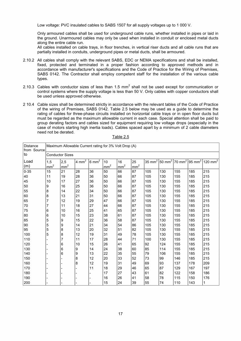
2 10.4 Cable sizes shall be determined strictly in accordance with the relevant tables of the Code of Practiceof the wiring of Premises, SABS 0142. Table 2.5 below may be used as a guide to determine therating of cables for three-phase circuits installed on horizontal cable trays or in open floor ducts butmust be regarded as the maximum allowable current in each case. Special attention shall be paid togroup derating factors and cables sized for equipment requiring low voltage drops (especially in thecase of motors starting high inertia loads). Cables spaced apart by a minimum of 2 cable diametersneed not be derated.
Table 2.5
Distancefrom Source
Maximum Allowable Current rating for 3% Volt Drop (A)
to Conductor Sizes
Load(m)
1,5mm2
2,5mm2
4 mm2 6 mm2 10mm2
16mm2
25mm2
35 mm2 50 mm2 70 mm2 95 mm2 120 mm2
0-35 15 21 28 36 50 66 87 105 130 155 185 21540 11 19 28 36 50 66 87 105 130 155 185 21545 10 17 27 36 50 66 87 105 130 155 185 21550 9 16 25 36 50 66 87 105 130 155 185 21555 8 14 22 34 50 66 87 105 130 155 185 21560 8 13 21 31 50 66 87 105 130 155 185 21565 7 12 19 29 47 66 87 105 130 155 185 21570 7 11 18 27 44 66 87 105 130 155 185 21575 6 10 16 25 41 65 87 105 130 155 185 21580 6 10 15 23 38 61 87 105 130 155 185 21585 5 9 15 22 36 58 87 105 130 155 185 21590 5 9 14 21 34 54 86 105 130 155 185 21595 5 8 13 20 32 51 82 105 130 155 185 215100 5 8 12 19 31 49 78 105 130 155 185 215110 - 7 11 17 28 44 71 100 130 155 185 215120 - 6 10 15 26 41 65 92 124 155 185 215130 - 6 9 14 24 38 60 85 114 155 185 215140 - 6 9 13 22 35 55 79 106 155 185 215150 - - 8 12 20 33 52 73 99 146 185 215160 - - 8 12 19 31 49 69 93 137 178 209170 - - - 11 18 29 46 65 87 129 167 197180 - - - - 17 27 43 61 82 122 158 186190 - - - - 16 26 41 58 78 115 150 176200 - - - - 15 24 39 55 74 110 143 1
18
2.10.5 Through joints will not be allowed in cables without the written permission of the Department'sRepresentative. Where joints are allowed and approved, they shall be installed in accordance withthe requirements of par. 2.11.2.
2.10.6 Unless clearly specified to the contrary, each cable run which forms part of the low-tensiondistribution system, and each cable feeding equipment, shall be provided with an earth continuityconductor. The earth conductor's minimum size and maximum length shall be selected inaccordance with the requirements of the Code of Practice or the Wiring of Premises, SABS 0142. Noearth continuity conductor shall be of a cross sectional area less than 2,5mm2.
The earth continuity conductor shall consist of:
A separate uninsulated stranded copper conductor installed along the same route as the associatedcable, or
One of the cable conductors, or Several strands of the wire armouring that have been replaced bycopper wires. (Refer to par. 2.12.2)
2.10.7 The armouring of an armoured cable shall be connected to the earth continuity conductor at bothcable ends and at all joints. The cross sectional area of the armouring at joints shall not be reducedand shall be made continuous across joints.
2.11 Paper Insulated Cables
2.11.1 Paper insulated cables shall comply with SABS 97 and shall be of the PILCSWA mass-impregnatedor pre-impregnated non-draining belted type. The conductors shall be of copper.
2.11.2 All joints and terminations shall be made either by means of compound filled boxes or by means ofepoxy-resin materials. Epoxy-resin joints and terminations shall be made entirely in accordance withthe manufacturer's instructions and with the materials stipulated.
2.11.3 If a cable is cut and will be exposed to the atmosphere for more than 2 hours, the cable ends shall besealed and the lead sheath wiped closed to prevent the ingress of moisture.
2.12 PVC Insulated Armoured Cables
2.12.1 All PVC/SWA/PVC cable shall comply with SABS 1507 and shall consist of PVC insulated copperconductors, PVC bedding, galvanised steel wire armouring and an extruded PVC outer sheath.
2.12.2 Cable ends shall be terminated in approved cable glands to ensure a moisture proof connectionbetween the outer sheath, gland and equipment.
In cases where copper earth conductors are included in the armouring (ECC/SWA cables), specialglands in accordance with SABS 1507 shall be used.
2.12.3 Cable glands shall be of the type in which the armouring is clamped between tapered cones,tightened down and fitted to a cable gland plate or equipment housing by means of lock nuts.
2.12.4 A neoprene shroud shall cover the gland externally and form an effective seal with the outer sheathof the cable.
2.13 XLPE Cables
2.13.1 XLPE cables will only be allowed inside substations between switchgear and transformers or within abuilding, i.e. a factory, workshop etc. and only with the prior written approval of the Department'sRepresentative.
2.13.2 Joints and terminations shall be made entirely in accordance with the manufacturer's instructions withthe materials stipulated in such instructions.
2.13.3 XLPE cables shall be in accordance with SABS 1339.
2.14 Installation of Cables
19
2.14.1 Lugs shall be crimped to cable core ends using mechanical or hydraulic tools designed for thispurpose. Evidence may be requested that the crimping method used complies with the performancerequirements of BS 4579, Part 1. Cables that are connected to clamp type terminals where theclamping screws are not in direct contact with the conductor, need not be lugged but the correctterminal size shall be used. Contact surfaces shall be thoroughly cleaned and smoothed and fixingbolts shall match the hole size of the lug.
2.14.2 High tension cables (voltages in excess of 600 V phase to earth) shall be installed away from othercables in separate floor trenches, pipes or ducts.
2.14.3 Single core cables for 3 phase supplies shall be installed in trefoil formation, with cables being inphysical contact.
2.14.4 Cables in floor trenches shall not be bunched in random fashion but shall be installed parallel to eachother. All floor trenches shall be covered with mild steel chequer plate of 6mm thickness and shall bepainted black.
2.14.5 The internal radius of a bend in a cable shall not be less than 12 times the overall diameter in thecase of a paper insulated or XLPE cable .and not less than 10 times the overall diameter in the caseof a PVC insulated cable.
2.14.6 Parallel cable runs on cable trays, etc. shall be separated by a minimum of 2 cable diameters unlessotherwise specified.
2.14.7 Where cable clamps are used, they shall be of non-combustible material and shall be of the correctsize for the cable.
2.14.8 All cables shall be marked at both ends and at all joints by means of non-corroding metal bands withpunched or embossed numbers. The numbers shall appear on the "as-built" drawings.
2.15 Cable Channels (Trunking)
2.15.1 The Contractor shall supply and install all cable channels as specified or as required by the cable andwiring installation including the necessary supports, hangers, fixing materials, bends, angles,junctions, T-pieces etc. He shall further liaise with the Main Contractor to verify the positions of holesand access routes through the structure and finishes.
2.15.2 Cable channels shall be in accordance with SABS 1197 and shall be manufactured of rolled sheetsteel of the following minimum thickness:
1,6 mm for ribbed channels with a maximum width of 42mm.
2,5 mm for un-ribbed channels with a maximum width of 42mm.
1.2 mm for channels with a width in excess of 42mm.
2.15.3 The channels shall be finished as follows:
In coastal areas (under all installation conditions) Hot-dip galvanised toepoxy powder coatedcoast).
SABS 763 (or if> 50km from
Cast in concrete Pre-galvanised
False ceiling voids Pre-galvanised.
Vertical building ducts Hot-dip galvanised toepoxy power coated.
SABS 763 or
Surface mounted in plant rooms, substations, servicetunnels and basements
Epoxy powder coated or electro-galvanised >50km from coast
20
Damp areas, exposed to weather, underground runs incontact with earth
Hot-dip galvanised toepoxy coated.
SABS 763 or
Undercover industrial applications Hot-dip galvanised toepoxy powder coated.
SABS 763 or
The above mentioned finishes shall apply unless specified to the contrary in the Detailed TechnicalSpecification. Epoxy powder coats shall comply with par. 3.7.6. Hot-dip galvanised or electro-galvanised channels shall be cold galvanised at all joints, sections that have been cut and at placeswhere the galvanising has been damaged. Powder coated channels shall likewise be touched up atjoints, cuts and damaged portions using spray canisters recommended by the manufacturer of thechannels.
2.15.4 All channels up to 125 mm wide shall have snap-in cover plates of metal or PVC. Cover plates forwider channels shall be of metal and shall be fixed by means of screws spaced at suitable intervals toprevent warping. The finish of the covers shall comply with par. 2.15.3.
2.15.5 Adjoining lengths shall be correctly aligned and securely joined by means of fish-plates fixed bymushroom bolts, washers and nuts or connection pieces that are pop-rivetted to both adjoiningsections. All adjoining sections shall be rectangular and butt tightly. Covers shall fit tightly across thejoint.
Where channels cross expansion joints in the concrete, suitable expansion joints shall be provided inthe channels by means of fish-plates pop-riveted or screwed to the channel on one side of theexpansion joint and floating freely in the channel on the other side of the expansion joint.
2.15.6 All conductors in inverted cable channels shall be retained by means of metal clips or metal spacerbars at not less than 1 m centres.
2.15.7 All cable channels shall be vermin proof after installation.
2.15.8 Electrical and mechanical continuity shall be maintained throughout the channel installation. A tinnedcopper bonding strip shall be placed across each joint and secured to both adjoining channels bymeans of brass bolts, nuts and washers. The channel shall be bonded to the earth bar of theassociated switchboard.
2.15.9 All tees and bends shall be of easy sweep design with 45° cornices. The inside edges of all jointsshall be smooth and, where necessary shall be lined with rubber cement or other suitable rubberisedcompound to prevent laceration of conductor insulation.
2.15.10 Multiple channel runs or internal metal partitions shall be used where conductors for power, controland other services are present.
2.15.11 Where vertical channel lengths exceed 5 m. conductors shall have intermediate fixings (refer to par.2.8.13).
2.15.12 Channels shall be large enough to ensure that the combined total cross-sectional area (includinginsulation) of all conductors does not exceed 40% of the cross-sectional area of the channel (refer topar. 2.8.6).
2.15.13 The Contractor shall supply and install all hangers, supports or fixings for the ducts. Channels up to75 x 75 mm shall be supported at maximum intervals of 600 mm and larger channels at maximumintervals of 1 m. Channel runs shall be carefully planned to avoid clashes with other services and toensure that all covers can be removed after completion of the entire installation and that all cablescan be inspected and removed or replaced without undue difficulty.
2.15.14 Where channels are cast into concrete, reinforced types shall be used. Additional spacer blocks shallbe used where necessary to prevent channels from being bent when the concrete is cast. Channelsshall be filled with polystyrene or other suitable fillers to prevent the ingress of cement and shall besecurely fixed in position to the shuttering.
2.15.15 Where channels pass through walls, a filling of fire retardant mineral fibre material (other thanasbestos) shall be installed around the conductors to serve as a fire barrier.

21
2.15.16 Purpose made cable clamps, hangers etc, shall be used only where required and shall be properlymanufactured.
2.15.17 All conduit connections shall be terminated by means of two lock nuts and a brass female bush. Allholes through which conductors pass shall be equipped with grommets.
2.16 Lighting
Lighting in plenum chambers shall consist of watertight bulkhead type light fittings. These lightingcircuits shall have earth leakage protection. Lighting fittings shall be in accordance with the standardspecifications of the Department for that particular type of luminaire.
3. SWITCHBOARDS AND CONTROL BOARDS
3.1 General
3.1.1 The Contractor shall determine the positions of all switchboards timeously and ensure that provisionis made in the structure for sleeves, pipes, access holes, etc. as required.
3.1.2 All switchboards shall be totally enclosed, vermin and insect proof, drip proof and dust proof to atleast class IP 42 of IEC 144 (refer to Appendix B).
3.1.3 Surface mounted switchboards shall be used only where they are not larger than 1200mm wide x1200 mm high and the mass is such that the switchboard can safely be supported by 4 expansiontype bolts on the surface of the wall. All other switchboards shall be of the floor standing type.
3.1.4 The name of the switchboard manufacturer shall appear on each switchboard.
3.2 Construction of Surface Mounted Switchboards
3.2.1 The switchboard shall consist of a 2 mm sheet metal enclosure, suitably braced with the necessaryreinforced fixings for wall mounting. All joints shall be welded. A 20 mm front edge, beyond which noequipment must protrude, shall be provided.
3.2.2 All equipment shall be mounted on a strengthened chassis, solidly fixed to the enclosure.
3.2.3 The front shall be covered by a hinged panel(s) with machine-punched slots and holes for the flushmounting of circuit beakers, instruments, indicator lights, push buttons, etc. Contactors, motorprotection units, etc. shall not protrude beyond the panel. Instruments, indicator lights and controlpushbuttons can also be mounted on the panel(s). The panel(s) shall have a square key operatedlock, solid hinges and a chromium plated handle.
Note: All front panels shall be hinged. Removable front panels with retaining pins and latch are notacceptable.
3.2.4 Switchboards shall not have doors unless specified.
3.3 Construction of Floor Standing Switchboards
3.3.1 Floor standing switchboards shall be totally enclosed, and shall be of multi-tiered, fixed pattern,sectional construction, allowing for the logical grouping of equipment behind individual hinged panels.All switchboards shall be suitable for mounting against a wall and shall provide for front access to allequipment and terminations but side. top and rear panels shall also be removable.
3.3.2 The switchboards shall consist of a solid angle iron, channel iron or 2 mm minimum thickness foldedmetal framework and solid U-channel base frame, sufficiently braced to support all equipment andspan floor trenches and access holes. The maximum height of the switchboard shall be 2,1 m.
3.3.3 Top, side and rear removable panels of 2 mm minimum steel shall be fixed with studs and chromiumplated brass dome nuts and washers or hank nuts and bolts.
22
3.3.4 Access to all sections of the switchboard shall be via hinged front panels consisting of 2 mmminimum sheet steel with square key operated non-ferrous fasteners designed to draw the panelclosed. Panels fixed by nuts and bolts or captive screws are not acceptable. Unhinged panels withretaining pins and latch are not acceptable. Hinged panels shall be dished with 20mm upturns and beequipped with rubber or neoprene seals. The panels shall be suitably braced and stiffened with top-hat sections to carry the weight of flush mounted equipment and to prevent warping. Long pedestaltype or similar hinges with two bolts per hinge section shall be used on all hinged panels for flushmounted protection relays and on panels higher than 600mm. Three hinges shall be provided onpanels higher than 1,5 m. Hinges with single bolts may only be used on smaller panels, notexceeding 300 mm X 300 mm. Hinges shall be arranged in opposed fashion so that panels cannotbe lifted off.
3.3.5 Busbars
The busbars shall be installed at the top of the switchboard with sufficient access even when theboard is installed against a wall. Busbar connections to equipment ("droppers") shall be insulated inaccordance with par. 3.4.5 and shall be suitably braced along their entire length to withstand themaximum fault current, which may be encountered. (Refer to par. 3.4.3). The insulating material shallwithstand the maximum fault level encountered (Refer to par. 3.4.3).
3.3.6 Cable Access
Adequate space shall be provided at the rear of switchboards for power cables and busbars forequipment. The cable connections and busbars shall be accessible from the front of the switchboard(refer to par. 3.3.1). Conductors for control, instrumentation, monitoring, alarm and for low voltagesupply circuits that are bunched and bound or installed in PVC wiring channels shall be installedalong the sides of the individual switchboard sections and shall be accessible from the front.
3.3.7 Cable Gland Plates
Sturdy gland plates to accommodate all power cables shall be provided within 300 mm of the bottomof the switchboard. The correct size hole to accommodate cable glands shall be made on site bymeans of chassis punches.
The board shall be provided with a P4000 support for cables in order to relieve the glands ofmechanical stress.
3.3.8 Terminations
Terminals for all outgoing control, instrumentation, monitoring, alarm and low voltage supply circuitsshall be located at the bottom and/or top of the switchboard and shall be accessible via hinged frontpanels. These terminals shall be installed away from terminals for power circuits. All out going circuitsmust terminate on numbered terminal strips. The correct terminal size shall be used for eachconductor. Only one conductor terminal will be allowed. Bridging contacts on the terminals shall beused for parallel-connected circuits. All outgoing power cables shall terminate within 300mm of thegland plate to avoid long leads. Where this is not possible, each lead must be separately braced.Power cable sizes up to and including 70mm2 may terminate on clamp type terminals where theclamping screws are not in direct contact with the conductor, but bears upon a clamping plate.Connection to the equipment can then be made with cables that are similarly connected to theterminals. All power cable sizes larger than 70 mm2 shall terminate on busbars that are connected tothe associated equipment. Conductors shall have lugs that are sweated or crimped. Looping ofincoming supply wiring to large circuit breakers and contactors, etc. is not acceptable. Each deviceshall be individually connected to the supply busbar.
3.3.9 Bolts and Nuts
Only cadmium-plated high tensile steel bolts and hexagonal nuts may be employed at busbar jointsand connection points. All nuts shall be provided with spring washers or be of the nylon-locking typewith washers. The largest possible size bolt that will fit into holes in lugs and fixing holes of equipmentshall be used in every instance. Bolts shall be of sufficient length that at least two but not more thanfive threads protrude beyond the nut. Where busbars terminating at the ends of switchboards areintended for future extension, these busbars shall be predrilled to accommodate the extension.Where prefitted space is specified for future equipment, the busbars in the proposed position shall be
23
predrilled and nuts and bolts shall be provided to accommodate the future busbars or cables feedingthe equipment.
3.3.10 Incoming Supply
Each switchboard shall be provided with a means to isolate the incoming supply. This may beachieved by the use of an isolator, circuit breaker (fixed or draw-out) or fuse switch, rated to makeagainst the full system fault at that point and break the full load current. (Also refer to par. 3.6.) Theincoming supply section containing switchgear. protection equipment, controls and instrumentationshall form a clearly labelled, self-contained unit behind one or more hinged panels.The operatinghandle of the isolator, circuit-breaker or fuse switch controlling the incoming supply shall protrudethrough the panel and shall be interlocked to ensure that the panel can only be opened when thesupply is off.
Equipment that cannot be flush mounted on the panel, shall be mounted on a suitable metal chassisand shall protrude through a close fitting cutout in the panel. All protection relays contained inenclosed units with glass fronts shall be flush mounted on the hinged panels, contactors, thermaloverload relays, etc. shall be mounted on a chassis behind the panel. Instrumentation shall beprovided as described in par. 9.1.
3.3.11 Motor Controls
The switchgear, protection and control equipment, instrumentation and monitoring equipment for thesupply circuits to motors or other electrically operated mechanical equipment shall be groupedseparately in the switchboard. Large switchboards shall be provided with individual compartments orsections in the switchboard for each sub-system, e.g. compressors, cooling towers with pumps andfans, etc. The individual compartments shall be arranged in a multi-tiered fashion with hinged panelshaving varying vertical dimensions, but with the same horizontal dimensions, to accommodatedifferent switching and control equipment ratings. Each motor circuit shall be provided with a positivemeans of isolation in compliance with the last section of par. 4.2.3. A clutch type operating handleinterlocked with the hinged panel to open in the "off' position only shall be provided for isolators ormoulded case circuit breakers that are not flush mounted. Withdrawable circuit breakers shall bemounted behind separate hinged panels. Where combination fuse switch units are used, these shallcomply with par. 7.7.4 and shall be installed flush in the board, the front cover of the unit forming thefront face of the board. Separate hinged panels shall be provided in this case for instrumentation andother control equipment. All instrumentation and controls shall be flush mounted on the hingedpanels. Protection relays in cases with glass front shall be flush-mounted. All contactors, fuses,separate protection units not housed in cases, control relays, etc. shall be mounted on a chassisbehind the hinged panel. Indicator lights shall be provided at the control position for all remotelycontrolled machines. Test pushbuttons for all indicator lights shall be provided. Time switches shallnot be located amongst switchgear. Instrumentation shall be provided as described in par. 4.2.21 and9.1.
A fire protection relay shall be provided in all control boards to initiate switching off of the air-conditioning or ventilating system in the event of a fire being detected in the areas served by thecontrol board, or the manually-operated fire alarm being activated.
3.3.12 Supplies to Heater Banks
Switchgear, controls and instrumentation for heater banks shall be grouped together in theswitchboard. Equipment for the control and protection of heater banks shall be provided as describedin par. 6. Ammeters and indicator lights shall be flush mounted on a hinged front panel.
All circuit-breakers shall be flush mounted on a chassis behind the hinged panels with punched cut-outs. It is essential that the fault level at the output to each heater unit does not exceed the rupturingcapacity of the circuit-breaker. Where necessary, heater circuits shall be subdivided into groups andprotected by HRC fuses and circuit breakers to limit the fault level. High-speed current limitingbreakers are not acceptable. The above provisions are also applicable in cases were separateswitchboards are provided to supply heater banks only.
3.3.13 Lighting and Other Circuits
The switchgear shall be contained in one place on the switchboard in one or more horizontal tiers,
24
MCB's shall be flush mounted on a chassis behind a hinged panel with machine punched cut-outs. Allinstruments, indicator lights and pushbuttons shall be flush mounted on the hinged panels. Timeswitches shall either be flush-mounted on the panels or mounted on a chassis behind the panel andshall protrude through a tight fitting cut-out in the panel. Contactors relays, etc. shall be mounted onthe chassis behind the front panel.
3.3.14 Earthing of Metal Parts
All non-current carrying metal parts of the switchboard including the framework, metal enclosures ofequipment, iron cores of contactors and transformers etc. shall be solidly earthed to the earth busbardescribed in par. 3.4.8. All hinged panels shall have a 4 mm2 flexible copper braid connection whichis bolted onto the panel and frame. Screw connections on finished surfaces shall be made with toothwashers.
3.3.15 Mounting of Equipment
The mounting of equipment shall comply with SABS 1180 where applicable. Equipment to bemounted on the chassis shall be mounted by means of bolts, washers and nuts or by bolts screwedinto tapped holes in the chassis plate. In the latter case the minimum thickness of the chassis plateshall be 2.5 mm. The latter method shall not be used where boards will be subject to vibration ormechanical shocks. Self-tapping screws will not be accepted.
In designing the switchboard the following requirements shall be strictly adhered to:
A minimum distance of 50 mm between any piece of equipment and the frame or internal partitioning.This minimum space is required on all sides of the equipment. In the case of a single row of single-pole circuit-breakers, the spacing on one side of the row may be reduced to 25 mm if the incomingside of the circuit-breakers is busbar connected.
A minimum of 75 mm between horizontal rows of equipment. The maximum outside dimensions ofequipment shall be considered.
Circuit-breakers up to a fault rating of 10 kA may be installed adjacent to each other. For higherratings minimum of 40 mm shall be allowed between circuit-breakers or isolators.Sufficient space shall be provided for wiring allowing for the appropriate bending radius. Space forfuture equipment shall be allowed as specified. Time switches shall not be located amongstswitchgear.
3.4 Busbars
3.4.1 General
All busbars shall be of solid drawn, high conductivity copper and shall comply with the relevantsections of BS 159 and BS 1433. Completed busbar installations shall withstand the full test voltagespecified in the relevant BS specification.
Busbars shall be divided into sections and jointed to overlap for a distance equal to twice the width ofthe bar to prevent localised heating. Contact surfaces shall be tinned (acid-base flux may not beused) or silver-plated and bolted down by cadmium-plated bolts and nuts with an applied torque inaccordance with SABS 784. Busbars shall be prepared for extension where they terminate at theends of switchboards.
3.4.2 Application
Busbars shall be provided for the following applications:
Distribution of supply voltage (main busbars)
Connection of equipment with ratings exceeding the current rating of 70 mm2 conductors.
Connection of outgoing circuits with current ratings in excess of that allowed for 70mm2 conductors.
25
Collector bars for parallel cables.
Connection bars for neutral conductors.
Earth busbars
Cable connections to miniature circuit-breakers
3.4.3 Rating
Busbars for system voltages up to 600 V shall be designed to withstand a test voltage of 2,5 kV for 1minute.
The maximum allowable temperature of busbars (including joints) carrying full load current in anambient temperature as specified, shall not exceed 80 °C. Unless different ambient temperatures arespecified, an ambient temperature of 35 °C shall be assumed with a maximum temperature increaseof 45 °C. Table 3.1 may be used as a guide in determining the busbar rating where the distancebetween the phase busbars is at least twice the distance of the longer side of the cross section with aminimum spacing of 50 mm and at least 150 mm from the sheet metal enclosure. It is howeveressential that the switchboard manufacturer shall make due allowance for the "proximity and skin"effects, the effect of ferrous enclosures, ventilation, etc. for the arrangement used in his switchboarddesign. Manufacturers shall where requested prove that the busbar design and enclosure complywith the temperature rise as specified above.
In addition to the current rating, busbars shall comply with the following fault level rating:
A = 8.2 x I x (t)^
where
A = minimum cross-section (mm2)
I = prospective fault current (kA)
t = maximum time in seconds required for protection equipment to clear the fault
(Minimum allowable value for t = 0.2 sec).
The busbars shall be fixed and supported at sufficient intervals to withstand the mechanical forcesencountered during the maximum fault current that can occur. The maximum allowable spacing ofbusbar supports for fault levels of 20 kA and more is 500 mm.
Where a busbar consists of 2 or more busbars per phase (laminations), the laminations shall beseparated by a minimum distance of the thickness of one lamination. The laminations shall beclamped together with copper spacers at intervals not exceeding 450 mm in order to equalise thecurrent distribution in the laminations.
The busbar ratings shown in Table 3.1 shall be multiplied by the factors shown in Table 3.2 todetermine the total current rating per phase:

26
TABLE 3.1 CURRENT RATING OF SINGLE COPPER BUSBARS (A)
Width Thickness (mm)(mm)
2,5 3,15 4,0 6,3 10 12,5 1612.5 155 18016 190 220 25020 230 265 30025 280 320 365 47031,5 340 385 440 56040 420 475 540 680 87050 510 575 650 820 1030 116063 790 990 1240 137080 970 1200 1480 1640100 1160 1430 1760 2180125 1710 2100 2310 2570160 2070 2530 2780 3090200 3290 3660250 3900 4300315 4630 5120400 6230
TABLE 3.2
DERATING FACTORS FOR LAMINATED BUSBARS
Area of Cross Section (mm2) No. of parallel busbars per phase
2 3 4
500 1,78 2,45 3,13
1 000 1,72 2,36 3,00
1 500 1,65 2,24 2,84
2000 1,60 2,16 2,70
2500 1,55 2,10 2,60
3000 1,52 2,02 2,52
3500 1,48 1,98 2,48
4000 1,44 1,96 2,45
3.4.4 Mounting of Busbars
All busbars shall be installed horizontally or vertically with the longer side of the cross section in thevertical plane. Main busbars shall be supported on approved resin bound synthetic wood panels orsimilar insulating material. These panels shall be firmly bolted to the switchboard frame and shall fittightly and neatly around the busbars. Busbars may also be mounted on resin insulators. Porcelaininsulators are not acceptable. It is essential that busbar supports shall be suitable to withstand the
27
maximum mechanical forces encountered during fault conditions.
The busbars shall withstand a fault current under test conditions of the specified fault level for 1sec. Ifa fault level is not specified, the busbars shall be tested at 20 times rated current for 1 second. Thefault current during tests shall be:
(a) between all three-phases.(b) any two phases.(c) neutral and the adjacent phase, and(d) earth conductor and the nearest phase conductor.
If no other methods are specified, the stresses under fault conditions shall be calculated as follows.taking into account correction factors for different configurations:
(a) Mechanical stresses
F = 16 x I² x k d x 10 000 N/m
Where
F = force (N/m)I = maximum fault current (A r.m.s. symm.)d = spacing between bars (m)k = space factor rectangular bars (see Fig. C 3.1)
(b) Temperature effects
Allow a maximum temperature to suit the type of insulation for the fault current flowing for 1,5sec, (i.e. 130 °C for PVC and 160 °C for heat resistant insulating material), using suitable I2curves and dT curves where
I = maximum fault current flowing for t sec.
A = bar cross-sectional area (mm2)
dT = temperature rise (°C)
Busbars shall be at least 150 mm from the nearest equipment. Busbar connections shall be arrangedto comply with par. 3.3.8. Where busbars protrude through a switchboard panel for incoming oroutgoing circuits, the busbars shall be properly insulated and rigidly supported on the inside of theswitchboard. This shall be achieved by means of resin bound synthetic wood or similar insulatingmaterial with cut-outs which fit tightly around the busbars. The insulating panel shall be firmly boltedto the frame. Busbars or "droppers" that pass through internal partitions in the switchboard shall besimilarly insulated and supported.
The minimum clearances between current carrying parts and other metal parts for system voltagesup to 600V is 10 mm in accordance with SABS 784 and BS 159 and shall be strictly maintained.
3.4.5 Insulation
All busbars shall be covered with coloured heat-shrinkable material approved by the Department. Thecolour shall correspond to the colour of the supply phase. Alternatively busbars may be covered withtwo coats of coloured insulation paint if approved by the Department. Busbar joints shall be coveredwith a suitable non-hardening compound and then taped with coloured PVC tape. Busbars shall beradius edged where they change direction.
Joints shall be insulated on site after installation on site and after the Department's representativehas checked the bolts. High-tensile steel bolts with washers and spring washers shall be used atjoints.
3.4.6 Connections to Busbars
All conductors and cables shall be bolted to busbars using crimped lugs. Cadmium plated steel bolts
28
and nuts. washers and lock washers shall be used.
3.4.7 Neutral Busbars
Neutral busbars in 3 phase, 4 wire supplies shall have a cross-section of at least 60 % of the cross-section of the phase busbars. Where single-phase circuits (e.g. lighting and general power circuits)are protected by single-phase circuit breakers or fuses, all neutral conductors shall be connected to aseparate neutral busbar mounted in a suitable position. The cross-section of the busbar shall be atleast 6.3 x 25 mm and the busbar shall be long enough for the lug of each conductor to be boltedseparately to the busbar. Only one neutral conductor is allowed per nut and bolt combination.
A separate neutral bar shall be provided for each earth leakage unit provided on the switchboard.
3.4.8 Earth Busbar
An earth busbar shall be installed in a convenient position along the entire length of the switchboard.All earth connections shall be bolted separately to the busbar as described in par. 3.4.6. The cross-sectional area of earth busbars shall be calculated according to the following formula in IEC 439 witha minimum cross-section of 6,3 x 25 mm:
S = l x (t) X (dT)
Where S = cross-section (mm2)
I = the r.m.s. value of the current (A)
X = 13 for copper
t = operating time of protective equipment (sec) (Minimum value = 0,2 sec.)
dT = temperature rise (°C)
= 120°C for insulated conductors
= 180°C for uninsulated conductors
If t is between 2 sec. and 5 sec. then dT can be increased in the same formula to:
dT= 145°C for insulated conductors
= 215°C for uninsulated conductors
In addition, the longer side of the earth busbar shall be at least twice the diameter of the largest boltthat will be fitted to the busbar. The earth bar shall be bolted to the frame of the switchboard. Brassearth strips with tapped holes and screws are not acceptable. Busbars with clamp type terminals thatfit over the bar, are acceptable as an alternative to bolted connections.
3.5 Conductors
3.5.1 Power Conductors
Connections between busbars and all equipment in the switchboard shall consist of heavy dutycoloured PVC insulated stranded annealed copper conductors and/or solid high conductivity copperbars of ample cross-section covered with heat shrinkable material. The colours to be used in allinstances shall be red, white and blue for phase connections and black for neutral connections. Allcircuits with a rating of 200A and more and all connections to cables larger than 70mm2 (refer to par.3.3.8) shall consist of busbars only.
29
3.5.2 Current Rating
The current rating of all conductors used for the internal wiring of switchboards shall be equal to thecapacity of the circuit breaker or fuse which protects the circuit and shall be determined according toTable 3.3.
Table 3.3 shall be applied for ambient temperatures up to 30°C. (Refer to Table 41.2 in VDE 0100).For higher ambients the values shall be derated as prescribed by SABS 0142.
TABLE 3.3 CURRENT RATING FOR INTERNAL WIRING
Nominal CONDUCTOR RATING (A)
cross-section
(mm2) Number of Conductors in bunch1 2-3 4-5 6-9 10 and more
2,5 28 25 22 19 16
4 37 33 30 26 226 47 42 38 33 2810 64 54 51 44 3816 85 76 68 59 5125 112 101 89 78 6735 138 124 110 96 8850 172 154 137 120 10370 213 191 170 149 127
3.5.3 Internal Wiring
Standard 600/1 000 V grade PVC-insulated stranded annealed copper conductors to SABS 1507shall be employed for the internal power wiring of switchboards. The smallest conductor size to beused for power wiring in switchboards shall be 2,5 mm2 Flexible cords of minimum size 1 mm2 maybe used for wiring of control instrumentation.
Where heat-generating equipment is present and the internal temperature of the board is likely toexceed 50°C on occasion, silicon-rubber insulated stranded conductors shall be used.
Wiring shall be arranged in horizontal and vertical rows and shall be bound with suitable plastic straps(cable ties) or installed in PVC wiring channels. Under no circumstances may PVC adhesive tape beused for the bunching of conductors or for the colour identification of conductors.
Bunched conductors shall be neatly formed to present a uniform appearance without twisting orcrossing the conductors. Conductors leaving the harnesses so formed shall be so arranged that theyare adjacent to the chassis. Conductors to hinged panels and doors shall be secured on both thedoor and the frame and shall be looped between the two points. The loop shall be arranged toproduce a twisting motion when the door is opened or closed. A flexible protection sleeve shall beinstalled over the conductors.
Where wiring channels are used, they shall be installed horizontally and vertically. Power and controlcircuit wiring may not be installed in the same wiring channel. Control wires are defined as thosecarfying voltages of 50 V or less. The wiring used for all control wiring shall be 600 V grade.
All wiring between different panels within the same switchboard shall be installed in wiring channels.
Grommets shall be installed in each hole in the metalwork through which conductors pass.All wiring shall be installed away from terminals, clamps or other current carrying parts. Wiring shall
30
also be kept away from exposed metal edges or shall be protected where they cross metal edges.
Conductors may be jointed at equipment terminals or numbered terminal strips only. No otherconnections are allowed.
Where conductors change direction, smooth bends shall be formed with a radius of at least 5 timesthe outside diameter of the conductor or harness.
Where screened cables are specified, the screening shall only be earthed in the switchboard orcontrol board, unless clearly specified to the contrary. Screened cables entering control boxesthrough pressed knock-outs shall terminate in compression glands. Conductors shall as far aspossible remain inside the screening at terminations. Where conductors have to separate from thescreen, the braiding shall be separated and the conductors drawn through the braid withoutdamaging the braiding. The conductors shall then be connected to their respective terminals and thescreening smoothed and connected to the earth terminal. For cables controlling electro-mechanicaldevices, no screening is necessary. Cables controlling electronic devices shall have high voltagescreening.
Where neutral or earth connections are looped between the terminals of instruments or otherequipment, it is essential that the two conductor ends be inserted into a common lug and are crimpedor soldered together in order that the neutral connection is not broken when the conductors areremoved from one of the instruments.
Conductors terminating on meters, fuse holders and other equipment with screw terminals shall befitted with crimped lugs.
Wiring should be confined to the front portions of switchboards as far as possible for ease of access.This requirement is important for wiring between circuit-breakers with a rating of less than 60 A andthe associated main circuit-breaker as well as the wiring from circuit-breakers to lighting and socket-circuits.
A maximum of two conductors will be allowed per equipment terminal. Where more conductors mustbe connected to the same equipment terminal (e.g. a main circuit-breaker feeding other circuit-breakers). stub busbars shall be provided for the various conductors.
3.5.4 Instrument Fuses
All instrument fuses shall be accessible from the front, located behind the front panels. Whereequipment is fed by busbars, the fuseholders shall be bolted directly onto the busbars. In othercases, conductors from the incoming circuit to the fuse shall be as short as possible. Each fuse shallbe separately labelled stating instrument circuit, phase and rating.
3.5.5 Identification of Conductors
The colour of all conductors for 400V or 230V AC circuits shall comply with the colour requirementsstated in par. 3.5.1. Conductors for DC circuits and earth connections shall be grey and greenrespectively in compliance with BS 158 but the conductors for control, alarm, interlocking andmeasuring circuits, shall preferably have different colours which are installed according to aconsistent colour code. Each conductor including conductors at terminals shall be marked at bothends by means of durable ferrule type cable markers. Cable markers specially manufactured for thispurpose shall be used. Hand-punched PVC or other tapes are not acceptable. The numbers of allconductors shall appear on switchboard drawings.
3.5.6 Cables
All cables for incoming or outgoing circuits shall terminate on a gland plate supplied for this purposeand be supported to take the force off the gland (refer to par. 3.3.7). Cable boxes for PILCA cablesshall be installed at the bottom of the switchboard. The conductors of cables shall either beconnected directly to the correct equipment if the equipment terminals are situated near the cablegland plate or shall terminate as described in par. 3.3.8. Long tails shall be avoided. Parallel-connected cables shall be connected to busbar strips without crossing the individual conductors.Each cable shall be individually identified by means of punched aluminium strips that are tied to thecables.
31
3.5.7 Neutral and earth conductors shall be connected as described in par. 3.4.7 and 3.4.8.
3.6 Essential and Non-Essential Supplies
3.6.1 "Essential supply" means that in case of a power interruption, standby power is either automaticallyor manually switched to these circuits from a standby power source. Special care shall be taken (a)to prevent any feedback from the "Essential" to the "Non-essential" supply or vice versa and (b) thatfan motor starting current does not exceed the capability of the standby power source. If necessary,special precautions must be taken to limit the motor starting current.
3.6.2 The switchboard shall be divided into electrically separate sections with sheet metal barriers to isolatethe "Essential" and "Non-essential" compartments.
3.6.3 A means shall be provided to isolate the standby and mains power supplies simultaneously.Mechanically interlocked circuit breakers or isolators are preferred. Electrically interlocked circuitbreakers or circuit breakers with shunt trips operated via an auxiliary contact on the main switch areacceptable. Six pole on-load rotary switches rated at 25% in excess of the maximum full load currentof the board may be used where the maximum system fault current at the board does not exceed 10kA.
3.6.4 A main switch shall be provided in both the "Essential" and "Non-essential" supply sections of theswitchboard. Each main switch must be interlocked with the access door or panel in that section toensure that the door can be opened only when the main switch is in the OFF position.
3.6.5 Mechanically interlocked circuit breakers or isolators or a 6 pole rotary switch (subject to theprovisions of par. 3.6.3) may be located in the "Essential" supply section of the switchboard in whichcase it will serve as the main switch for the switchboard as a whole and the "Essential" supplysection. An additional isolator or circuit breaker shall then be provided as main switch for the "Non-essential" supply section.
3.6.6 Each section of the switchboard shall be constructed in accordance with par. 3.1 - 3.5.
3.7 Paint Finish
3.7.1 Finish required
Metalwork of electrical equipment such as switchboards, equipment enclosures, purpose-madeboxes. - etc. shall be finished with a high quality paint applied according to the best available method.Baked enamel, electrostatically applied powder coating or similar proven methods, other thanstandard enamel paint applied by brush, shall be used.
3.7.2 Corrosion resistance
Painted metal shall be corrosion resistant for a period of at least 168 hours when tested inaccordance with SABS Standard Method 155.
3.7.3 Edges
Care shall be taken to ensure that all edges and corners are properly covered, after all burrs andsharp edges have been removed.
3.7.4 Surface preparation
Surface preparation shall comply with SABS 064. Prior to painting, all metal parts shall be thoroughlycleaned of rust, mill scale, grease and foreign matter to a continuous metallic finish. Sand or shotblasting or acid pickling and washing shall be employed for this purpose.
3.7.5 Baked enamel finish
3.7.5.1 Immediately after cleaning, all surfaces shall be covered by a rust inhibiting, tough, unbroken metal-phosphate film and then thoroughly dried.
32
3.7.5.2 Within 48 hours after phosphating. a passivating layer consisting of a high quality zinc chromateprimer shall be applied followed by two sprayed coats of high quality alkyd-based baked enamel.
3.7.5.3 Baking enamels on other metal parts such as switchboard panels etc. shall comply with SABS 783,Type IV with a minimum paint thickness after baking of 0,06 mm.
3.7.5.4 The paint shall have an impact resistance of 5,65 J on cold-rolled steel plate and a scratch resistanceof 2 kg.
3.7.6 Powder coated finish (May only be used more than 50km from the coast and when protected byshelters or when situated within buildings as well as normally dry areas).
3.7.6.1 Immediately after cleaning, the metal parts shall be pre-heated and then covered by a microstructured paint powder applied electrostatically.
3.7.6.2 The paint shall be baked on and shall harden within 10 minutes at a temperature of 190°C.
3.7.6.3 The minimum paint thickness after baking shall be 0,05 mm and the paint cover shall have a impactresistance of 5,65 J on cold-rolled steel plate and a scratch resistance of 2 kg.
3.7.7 Touch-up paint
In the case of switchboards and larger equipment enclosures, a tin of matching touch-up paint notsmaller than 1 litre shall be provided.
3.7.8 Colours
3.7.8.1 The colour of LV switchboards and equipment enclosures in buildings shall be "LIGHT ORANGE",colour B26 of SABS 1091 as recommended in SABS 0140. Part II unless specified to the contrary.
3.7.8.2 The colour of LV distribution kiosks shall be "LIGHT STONE", colour C37 or "BEIGE" colour C34 ofSABS 1091.
3.7.8.3 The standby power section of LV switchboards in buildings shall be coloured "SIGNAL RED", colourAll of SABS 1091.
3.7.8.4 The distribution boards for No-Break Power Supplies shall be coloured "DARK VIOLET', colour F06or "OLIVE GREEN", colour H05 of SABS 1091.
3.8 Labelling
3.8.1 Labels
Care shall be taken to ensure that all equipment is fully labelled and that accurate descriptions andsafety warning notices appear in both English and one of the local spoken languages.
Labels shall be provided:
to identify each switchboard and each outgoing circuit, and
for all equipment on the inside and outside of the switchboard indicating function and rating. Labelsshall correspond to the equipment description on circuit diagrams.
Each piece of equipment shall have a separate label. Combined labels on long label strips, e.g. forsingle pole circuit breakers are not acceptable. Each label shall be separately removable.
3.8.2 Material
Engraved plastic or ivory sandwiched strips shall be used throughout. The strips shall bear whitelettering on a black background for normal labels and red letters on a white or yellow background fordanger notices.

33
3.8.3 Main Switchboards
Main switchboards and sub-main switchboards shall be supplied with the following bilingual labels:
3.8.3.1 Number and allocation of switchboard.
Example:
CONTROL BOARD A4BEHEERBORD A4 (Note: The second language to be approved by the Department's Representative)
Lettering at least 10 mm high. Label on the outside in a prominent position.
3.8.3.2 Designation of busbar sections.
Example:
BUSBAR SECTION 2GELEISTAMSEKSIE 2 (Note: The second language to be approved by the Department'sRepresentative).
Lettering at least 10 mm high. Label on the outside in a prominent position.
3.8.3.3 Designation of all switchgear including circuit-breakers, isolators, contactors, etc. If the current ratingof circuit-breakers is not clearly marked on the equipment, the value shall be indicated on theengraved label.
Example:
SUPPLY TO BOARD C3TOEVOER NA BOARD C3 (Note: The second language to be approved by the Department'sRepresentative)
PUMP SUPPLYPOMPTOEVOER (Note: The second language to be approved by the Department's Representative)
Lettering at least 5 mm high. Label on the outside of the switchboard.
3.8.3.3 All other equipment including meters, instruments, indicator lights, switches, pushbuttons, circuit-breakers. fuses, contactors, control relays, protection relays, etc. shall be identified. The function ofthe equipment and circuits shall be clearly indicated. The main switch shall be labelled as such anddesignated :
"SWITCH OFF IN CASE OF EMERGENCY""SKAKEL AF IN NOODGEVAL" (Note: The second language to be approved by the Department'sRepresentative)
Flush mounted equipment within doors or front panels shall be identified with labels fixed to the doorsor front panels respectively. The labels for equipment installed behind panels, shall be fixed to thechassis close to the equipment. If this equipment is positioned too close together to accommodatedescriptive engraved labels, the equipment may be identified by a code or number on an engravedlabel, which shall be fixed close to the equipment. The code number shall be identified on a legendcard, which shall be installed on the switchboard behind a perspex or other protective cover.
3.8.4 Other Switchboards
All equipment on switchboards shall be identified with the necessary bilingual labels. The circuitnumbers shall appear at grouped single-pole circuit breakers. The circuit number shall correspond tothe circuit numbers on the final installation drawings. The above mentioned circuits shall be identifiedon a legend card, which shall be installed on the inside of the switchboard door, or in any other

34
position where it can conveniently be observed. All fuses, including instrument fuses, shall havelabels stating function, fuse rating and duty or type where applicable. All other equipment shall beidentified separately and their functions shall be clearly indicated.
3.8.5 Fixing of Labels
Labels shall not be fixed to components or trunking but to doors, panels, chassis or other permanentstructures of the switchboard.
Engraved strips shall be secured in such a way as to facilitate a neat alteration of the designation ofthe labels. The labels shall not be glued to the switchboard. Sufficient fixing points shall be providedto prevent labels from warping. Labels in slotted holders shall be secured in position to preventunauthorized removal. The following means of securing labels are acceptable: brass bolts and nuts.self-tapping screws, slotted label holders and pop-rivets.
3.9 Tests
The function of all equipment, control, interlocking and measuring circuits shall be tested to the entiresatisfaction of the Department's Representative. All protection relays and ammeters shall be provenby means of secondary current injection. Test certificates of current transformers, capacitor banks,etc. shall be submitted.
Polarity tests and primary current injection tests to prove the winding ratios shall be conducted on allcurrent transformers. The Contractor shall supply all test equipment, test facilities, dummy loads andadditional switchgear and wiring at both the factory and on site at his cost. The Department shall benotified in writing 2 weeks before the commencement of tests so that they may witness the tests. Acomplete test report shall be submitted to the Department.
3.10 Drawings
3.10.1 Drawings for approval
As soon as possible but not later than 4 weeks after award of the Contract, the contractor shall, at hisexpense submit to the Department for approval 3 prints of drawings of:
A complete circuit and control diagram of the switchboard and all circuits connected to theswitchboard;
A dimensioned general arrangement drawing showing the position of all equipment on switchboards.The position and method of support of all busbars shall be clearly shown;
A list of all labels to be used in both English and the local languages as approved by theDepartment's Representative;
The make and catalogue number of all equipment showing the ratings of isolators, contactors,starters. circuit breakers, and the function of all controls, push-buttons, indicator lights, etc.;
All equipment and controls connected to the switchboard, clearly identifying the size, function andpurpose of each component, including motors, thermostats, microswitches, lock-out stops, etc.
3.10.2 A complete list of drawing symbols shall be provided on each electrical circuit and control drawing.
3.10.3 The approval of drawings shall not relieve the Contractor of his liability to carry out work inaccordance A with the terms of the Contract. The Contractor shall not proceed until the drawingshave been approved in writing.
3.10.4 Final Drawings
Upon completion of the Installation, the Contractor shall hand to the Department's Representative aset of transparent drawings of the entire installation. These drawings shall show all items in 3.10.1above and all terminal numbers and the numbers and colours of conductors used for the internalwiring. These drawings shall be up-to-date "as built" drawings containing all modifications.
The Contractor shall mount a copy of each drawing showing the circuit and control diagrams of the

35
complete installation, on a wall in the plant room.
The drawing shall be positioned in an accessible position and shall be mounted in a wooden framebehind plastic. Where necessary, more than one drawing shall be mounted on the wall in caseswhere the system schematic and the switchboard diagram cannot be shown on the same drawing.The drawings shall be chemically treated to prevent fading occurring.
3.10.5 Manuals
The Contractor shall at his cost furnish the Department with 3 copies of operating and maintenancemanuals for the entire system as well as major component parts of the system, includingcompressors, heaters, boilers, pumps and all main switchboards and motor control centres and forany other components and switchboards which the Department's Representative may deemnecessary. These manuals shall contain the following information.
A description of the operation of the equipment.
A maintenance manual.
Descriptive brochures or pamphlets of the equipment.
A complete equipment list indicating quantities and relevant catalogue numbers.
3.10.6 Completion
The Contract will be considered incomplete until all tests have been conducted to the satisfaction ofthe Department's Representative and all drawings and manuals have been handed to theDepartment.
4. MOTORS. STARTERS AND MOTOR PROTECTION
4.1 Motors
4.1.1 All electric motors shall comply fully with the relevant standard specifications: SABS 948: StandardSpecification for Three-phase Induction Motors. SABS IEC 34: Rotating Electrical Machinery.
4.1.2 Standard Squirrel Cage Motors shall be three-phase, (or single-phase up to 3 kW), continuouslyrated, screen-protected drip-proof, suitable for direct-on-line or star-delta starting.
High-starting-torquesquirrel-cage motors shall be three-phase, continuously rated, screen-protecteddrip-proof. with a special arrangement of rotor conductors giving high starting torque and moderatestarting current and suitable for direct-on-line or star-delta starting.
Slip-ring motors shall be three-phase, continuously rated, screen-protected drip-proof, withcontinuously rated slip rings and brushes and brushgear suitable for automatic starting.
Fractional kW motors shall be continuously rated, totally enclosed single-phase, capacitor-startinduction-run type, shaded pole or three-phase squirrel-cage where required.
Motors suitable for part-wound starting shall be three-phase, continuously rated, screen-protecteddrip-proof with wound rotor circuits suitably rated to provide continuous full load power when fullyswitched and to provide starting in graded steps sufficient to overcome the starting load torquewithout exceeding the specified starting current.
Hermetically sealed motors shall be three-phase squirrel cage motors, totally enclosed with a suitableinternal cooling medium and suitable insulation to provide continuous full load power under thespecified ambient conditions.
Pole-changing motors shall be three-phase, continuously rated, screen-protected drip-proof with cagerotor and separate stator windings providing several numbers of poles with various interconnectionsof the windings. The use of pole-changing motors to alleviate starting conditions shall be limited to2:1 speed ratios. Additional speed ratios shall only be used where the driven load specifically so
36
requires.
Pole-changing rotor circuits are not recommended and shall only be used in exceptionalcircumstances with the prior approval of the Department. Dahlander connections providing a 2:1speed ratio with variable torque and variable power characteristics of the motor may be used to drivecentrifugal pumps. Dahlander connections providing constant torque characteristics may be used forhigh friction loads and connections providing constant power characteristics may be used forconstant power loads viz. machine tools.
4.1.3 Motors with a speed in excess of 1500r/min. except in the case of centrifugal and rotary vanecompressors and close-coupled pumps, will not be accepted unless agreed to by the Department.
4.1.4 When determining motor rating, the following shall be taken into account:
All motors shall be rated for continuous full load duty.
The Continuous Maximum Rating (CMR) of the motor shall be 20% in excess of the full load runningduty of the load in order to withstand the tolerance of 105% -120% in the tripping characteristics ofoverload protection devices allowed in BS 4941, Part I.
All starting times, irrespective of the load characteristic for DOL starting, shall be limited to 20seconds unless prior approval to the contrary is obtained from the Department. The safe locked rotortime shall be well in excess of the run-up time to allow protection discrimination.
All motors shall be capable of a minimum of three consecutive starts per hour with the loadconnected and employing the method of starting to be installed without exceeding the allowedtemperature limits of the insulation. In addition, the motor shall be capable of the number of starts perhour for the particular load as may be specified or as may be experienced under normal operatingconditions.
Unduly over-rated motors resulting in a low power factor and efficiency are not acceptable.
The motor starting torque and speed/torque characteristics shall be carefully matched to that of theload to ensure that the motor does not stall at a low speed. A safety margin shall be allowed toovercome voltage drops and load fluctuations. The maximum torque developed by the motor in itsfinal running condition (i.e. when the motor is switched to its final running configuration in the case ofpole-changing motors and all starting devices have been switched out of circuit in the case ofassisted starting) shall be 1.6 times the rated full load torque to overcome temporary overloads andvoltage fluctuations.
The actual ambient temperature in which the motor will be operating (and not the prevailing outsideambient temperature only) shall be taken into account.
4.1.5 It is a requirement that the above information and any other requirements that will affect the type ofmotor to be used, be submitted to the motor manufacturer when ordering the motor. The Contractormay at the discretion of the Department be required to submit written proof that the motormanufacturer will guarantee the performance of the motor for the expected duty and load.
4.1.6 Special attention shall be paid to the. starting requirements of motors. The motor startingrequirements of par.4.2.4. and 4.2.5 shall apply unless stated otherwise in the Detailed TechnicalSpecification or written permission to the contrary has been obtained from the Department. It isessential that the starting torque produced by motors under the starting conditions specified, will besufficient to accelerate the load within the time period allowed by the manufacturer of the motor witha maximum starting time of 20 seconds (refer to par. 4.1.4 above). The Contractor may be requiredto submit calculations showing accelerating torque available, load torque characteristics and run-uptime. The following formula may be used to calculate the run-up time:
Te = ((T!/T2) – 1)(T1 + T2) t = GD²N / (9,55 Te) ((T1/T2) + 1) loge (T1/T2)
where
Te = equivalent accelerating torque in Nm
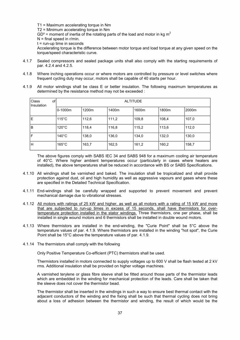
37
T1 = Maximum accelerating torque in NmT2 = Minimum accelerating torque in NmGD² = moment of inertia of the rotating parts of the load and motor in kg m2
N = final speed in r/min.t = run-up time in secondsAccelerating torque is the difference between motor torque and load torque at any given speed on thetorque/speed characteristic curve.
4.1.7 Sealed compressors and sealed package units shall also comply with the starting requirements ofpar. 4.2.4 and 4.2.5.
4.1.8 Where inching operations occur or where motors are controlled by pressure or level switches wherefrequent cycling duty may occur, motors shall be capable of 40 starts per hour.
4.1.9 All motor windings shall be class E or better insulation. The following maximum temperatures asdetermined by the resistance method may not be exceeded :
Class ofInsulation
ALTITUDE
0-1000m 1200m 1400m 1600m 1800m 2000m
E 115°C 112,6 111,2 109,8 108,4 107,0
B 120°C 118,4 116,8 115,2 113,6 112,0
F 140°C 138,0 136,0 134,0 132,0 130,0
H 165°C 163,7 162,5 161,2 160,2 158,7
The above figures comply with SABS IEC 34 and SABS 948 for a maximum cooling air temperatureof 40°C. Where higher ambient temperatures occur (particularly in cases where heaters areinstalled), the above temperatures shall be reduced in accordance with BS or SABS Specifications.
4.1.10 All windings shall be varnished and baked. The insulation shall be tropicalized and shall provideprotection against dust, oil and high humidity as well as aggressive vapours and gases where theseare specified in the Detailed Technical Specification.
4.1.11 End-windings shall be carefully wrapped and supported to prevent movement and preventmechanical damage due to vibrational stresses.
4.1.12 All motors with ratings of 25 kW and higher, as well as all motors with a rating of 15 kW and morethat are subjected to run-up times in excess of 15 seconds, shall have thermistors for over-temperature protection installed in the stator windings. Three thermistors, one per phase, shall beinstalled in single wound motors and 6 thermistors shall be installed in double wound motors.
4.1.13 Where thermistors are installed in the end-winding, the "Curie Point" shall be 5°C above thetemperature values of par. 4.1.9. Where thermistors are installed in the winding "hot spot", the CuriePoint shall be 15°C above the temperature values of par. 4.1.9.
4.1.14 The thermistors shall comply with the following
Only Positive Temperature Co-efficient (PTC) thermistors shall be used.
Thermistors installed in motors connected to supply voltages up to 600 V shall be flash tested at 2 kVrms. Additional insulation shall be provided on higher voltage machines.
A varnished terylene or glass fibre sleeve shall be fitted around those parts of the thermistor leadswhich are embedded in the winding for mechanical protection of the leads. Care shall be taken thatthe sleeve does not cover the thermistor bead.
The thermistor shall be inserted in the windings in such a way to ensure best thermal contact with theadjacent conductors of the winding and the fixing shall be such that thermal cycling does not bringabout a loss of adhesion between the thermistor and winding, the result of which would be the

38
appearance of an air gap and reduced sensitivity.
All leads from thermistors to the protection control units shall be twisted pairs to minimise strayvoltage pick-up. Screened cables shall be used where the control units are far from the motor. All thethermistors acting on one control unit shall be connected in series.
4.1.15 Where thermistors are installed it is essential that relay panels be safeguarded against high voltagesin case of a short circuit between sensor and motor windings. Isolation transformers arerecommended for this purpose.
4.1.16 The housing, end-shields and feet of totally enclosed surface-cooled motors shall be of cast iron toBS 1452. Standard protected, internally cooled motors may be of welded steel construction. Acondensation hole shall be provided at the lowest point in the motor frame.
4.1.17 It is essential that the correct mounting type is selected for each application.
4.1.18 Motor terminals shall be clearly marked. U. V. W. or U1. V1, W1 and U2. V2. W2. An earth terminalshall be provided at a convenient position on the motor frame. Vulcanised rubber insulation shall notbe used for the connection from windings to the terminals.
4.1.19 When viewed from the drive shaft end, the motor rotor shall rotate in a clockwise direction when theR-W-B supply leads are connected to the U-V-W motor terminals.
4.1.20 All terminals shall be totally enclosed in a waterproof box sealed with gaskets and shall be completewith nuts, lock-nuts, lugs. etc. Cable boxes for PILCA cables shall be complete with tinned brasswiping gland and armour clamps. PVC cable shall be terminated using compression glands withshroud. Cables shall be provided with a means of support to remove the weight of the cable from thegland (refer to par. 3.3.7). All terminal boxes shall be large enough to ensure proper termination ofthe cables and connection of cores without exceeding the allowable bending radius. All terminalboxes shall be capable of being rotated through 360°. Where condensation may form on motorterminals, e.g. certain centrifugal refrigeration compressors, terminal boxes shall be hermeticallysealed and filled with silica-gel.
4.1.21 Bearings shall be protected against possible shaft eddy currents and shall be suitable to withstandvibrations cause by reciprocating or unbalanced loads.
4.1.22 Anti-condensation heating elements shall be provided In the motor windings for the following motorapplications:
Close-coupled motors and pumps in chilled water systems.
Standby motors in refrigeration Installations where the ambient air surrounding the motor may dropbelow the dew point.
Pumps installed in damp areas where the pumps will not run continuously. Fans in kitchen canopiesand fume cupboards.
The heating elements shall be arranged to prevent terminals and exposed connections becomingdamp. The heating element must be disconnected before the motor is started up. As an alternative toheating elements, a low voltage transformer (approx. 50 V) can be switched into the circuit when themotor is stationary to provide a continuous circulating current in the motor windings.
4.1.23 Where requested copies of type.test certificates for routine and performance tests in accordance withSABS 948 and SABS IEC 34 shall be submitted before delivery of the motors. In addition, themanufacturer's guarantee (refer to par. 4.1.5.) that the motor will comply with the duty as described inpar. 4.1.4, shall be submitted. Curves of Torque/Speed and Current/Speed shall be provided onrequest.
4.1.24 The Department reserves the right to witness all routine or performance tests and shall be notified inwriting 14 days before the commencement of such tests.
4.1.25 Motors that have become damp shall be dried out before connection to the supply. Damaged motorsresulting from non-compliance with this requirement, shall be rectified by the Contractor at his cost.

39
4.2 Motor Starters
4.2.1 Starters shall be provided for all electrically driven mechanical equipment and shall be as specified orotherwise required by local supply authorities or system requirements.
4.2.2 All contactors and starters shall comply with SABS IEC 947. BS 587. BS 4941 and BS 5856 asapplicable. Where sail or float switches are used in the ON/OFF control circuit, inherent time delaysor other protection shall be built into the control circuit to prevent hunting or chatter of the startercontactor at or near the switching point.
4.2.3 All electrically driven mechanical equipment shall be provided with a means of isolating the electricalsupply from the equipment by one of the following methods:
An isolator on the equipment (refer to par. 4.2.19).
A motor starter with positive manual stop control and isolating characteristics, mounted within 2 m ofthe equipment.
A separately mounted on-load isolator within 2 m of the equipment in cases where the starter ismounted further away from the equipment (refer to par. 4.2.18). The isolator shall have "locked rotor"breaking capacity in the case of motor circuits. As an alternative, lock-out stops located within 2 m ofthe equipment which trip the operating contactor may be used on condition that lockable type circuitisolation is provided on the Control Board and on condition that this arrangement is acceptable to theSupply Authority.
Each circuit shall in addition be provided with an on-load isolator, circuit breaker or combination fuseswitch unit on the control board to which the circuit is connected. These devices shall have "lockedrotor" breaking capacity in the case of motor circuits.
4.2.4 The method of starting shall in all cases comply with the requirements of the local Supply Authority.The following schedule of starting requirements will apply unless the Supply Authority prescribesmore stringent requirements or unless written permission to the contrary has been obtained from theDepartment (refer to par. 4.1.6).
NOTE : "Reduced Voltage Starting" includes
- Star-Delta starters (par. 4.2.9).- Auto-Transformer starters (par. 4.2.10),- Liquid starters (par. 4.2.11),
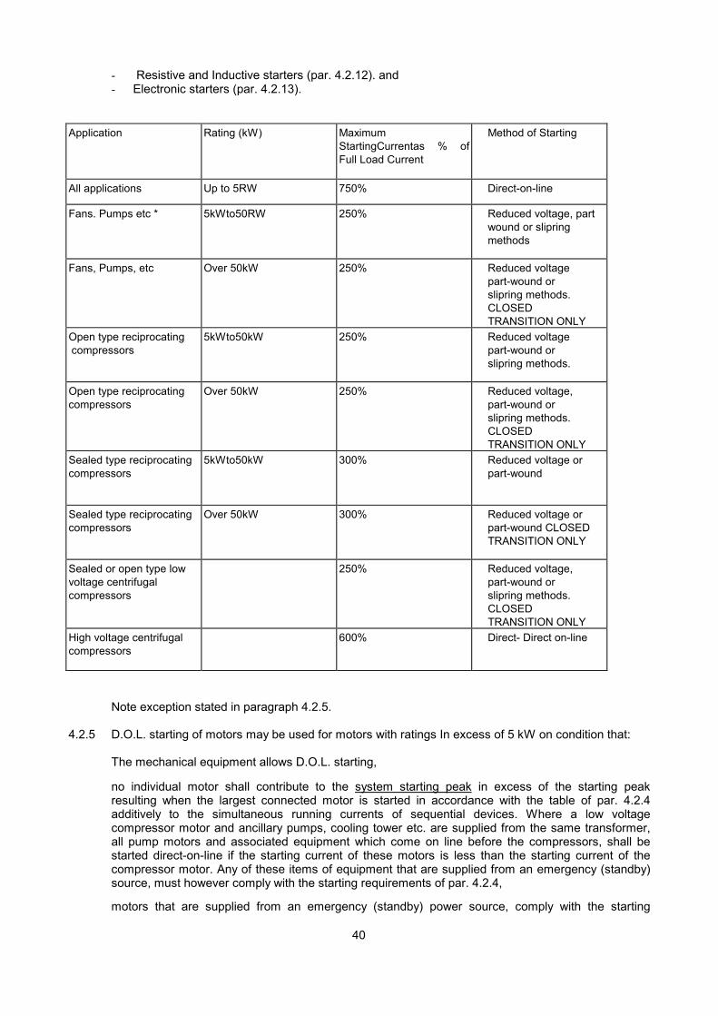
40
- Resistive and Inductive starters (par. 4.2.12). and- Electronic starters (par. 4.2.13).
Application Rating (kW) MaximumStartingCurrentas % ofFull Load Current
Method of Starting
All applications Up to 5RW 750% Direct-on-line
Fans. Pumps etc * 5kWto50RW 250% Reduced voltage, partwound or slipringmethods
Fans, Pumps, etc Over 50kW 250% Reduced voltagepart-wound orslipring methods.CLOSEDTRANSITION ONLY
Open type reciprocatingcompressors
5kWto50kW 250% Reduced voltagepart-wound orslipring methods.
Open type reciprocatingcompressors
Over 50kW 250% Reduced voltage,part-wound orslipring methods.CLOSEDTRANSITION ONLY
Sealed type reciprocatingcompressors
5kWto50kW 300% Reduced voltage orpart-wound
Sealed type reciprocatingcompressors
Over 50kW 300% Reduced voltage orpart-wound CLOSEDTRANSITION ONLY
Sealed or open type lowvoltage centrifugalcompressors
250% Reduced voltage,part-wound orslipring methods.CLOSEDTRANSITION ONLY
High voltage centrifugalcompressors
600% Direct- Direct on-line
Note exception stated in paragraph 4.2.5.
4.2.5 D.O.L. starting of motors may be used for motors with ratings In excess of 5 kW on condition that:
The mechanical equipment allows D.O.L. starting,
no individual motor shall contribute to the system starting peak in excess of the starting peakresulting when the largest connected motor is started in accordance with the table of par. 4.2.4additively to the simultaneous running currents of sequential devices. Where a low voltagecompressor motor and ancillary pumps, cooling tower etc. are supplied from the same transformer,all pump motors and associated equipment which come on line before the compressors, shall bestarted direct-on-line if the starting current of these motors is less than the starting current of thecompressor motor. Any of these items of equipment that are supplied from an emergency (standby)source, must however comply with the starting requirements of par. 4.2.4,
motors that are supplied from an emergency (standby) power source, comply with the starting
41
requirements of par. 4.2.4, and
that the Supply Authority approves the above arrangement.
4.2.6 Starters and contactors for fractional kW motors shall be rated at 1,2 kW minimum. All other startersshall have a minimum rating of 20 A purely inductive load.
4.2.7 All non-direct-on-line starters shall have inherent no-voltage release characteristics and shall beinterlocked to prevent starting in the direct-on-line mode.
4.2.8 Direct-on-line (D.O.U Starters
All D.O.L. starters shall be capable of 15 starts per hour except where plugging duty is required whenstarters shall be rated for 40 starts per hour.
Where motors are not switched frequently, electrically operated circuit breakers with overload, single-phase and undervoltage protection devices fitted, may be used as D.O.L. starters.
4.2.9 Star-Delta Starters
All star-delta starters used to switch motors with a rating in excess of 50 kW, shall be closedtransition arranged according to the Wauchope resistance system.
The resistors shall be so sized to ensure that the transient currents in no Instance exceed the startingcurrents stated in the table of par. 4.2.4.
All star-delta starters including resistors where applicable shall be rated for 15 starts per hour unlessautomatic time delays are incorporated which will prevent more frequent starts than the starter ratingallows. In no case however shall ratings be less than 3 consecutive starts per hour. Starters forplugging duty shall be rated at 40 starts per hour.
The timers for open transition star-delta starters shall be a break-before-make, snap acting type witha minimum of 50 ms and a maximum of 120 ms between break and make in order to quench the arcon the star contactor but to prevent magnetic flux decay in the motor with consequent high transients.The type of timer supplied shall be approved by the Department prior to manufacture of the starter. Ifthis type of timer is not provided, the star and delta contactors shall be electrically and mechanicallyinterlocked. In any starter above 37 kW. mechanical interlocking shall be obligatory.
All star-delta starters shall be electrically interlocked via N/C contacts on the contactors.
The timing and control circuit for closed transition star-delta starters shall be designed to employ onlyone timer to initiate the star-to-delta change-over. The closed transition switching shall be inherent inthe arrangement of the auxiliary contact operation. A "policeman" timer to protect the transitionresistance for motors up to 100 kW shall be provided if specified in the Detailed TechnicalSpecification. For motors above 100 kW, a "policeman" timer shall always be provided.
An overall "policeman" timer shall be provided on all closed transition star-delta starters in addition tothe star-delta change-over timer to disconnect the load if the total allowable starting time is exceeded.The make and principle of operation e.g. electronic vs. electro-mechanical, shall be different from thestar-delta timer. On 2-wire control systems the "policeman" timer must lock out and shall be manuallyreset in order to prevent re-cycling.
The thermal overload protection shall be fitted in the winding connection to the motor and not in theline connection except as stated in par. 4.3.16.
4.2.10 Auto-Transformer Starters
The tappings of auto-transformer starters shall be arranged to limit the starting and transient currentsto values stated in the table of par. 4.2.4.
Auto-transformer starters shall be arranged as follows:
Up to 20 kW - open delta20 - 50 kW - 3 leg auto-transformer

42
Above 50 kW - closed transition (Korndorfer)All auto-transformer starters shall have time delays incorporated to limit the number of starts per hourto the rating of the transformer. Alternatively, manual reset thermostatic cut-outs shall be provided toprotect the transformer. This rating shall, however, not be less than 4 starts per hour.An overall "policeman" timer shall always be provided in addition to the change-over timer in the caseof 3 leg and closed transition auto-transformer starters to disconnect the system if the total allowablestarting time is exceeded. The make and principle of these timers shall differ (refer to par. 4.2.9above).
4.2.11 Liquid Starters
Stator connected liquid starters rotor connected liquid starters may be used on all load applications.All starters shall be 3 phase units.
The starters shall be designed to start the motor in compliance with par. 4.1.4, 4.2.7 and the startingcurrents in the table of par. 4.2.4.
Liquid starters shall provide a smooth accelerating torque curve up to the final switch-over. The short-circuiting contactor shall be rated for the full load duty of the motor.
All the necessary data concerning the motor full load and starting characteristics shall be supplied tothe manufacturer who shall determine the design of the starter and the composition of the electrolyte.The type of electrolyte and composition shall be indelibly stamped on a nameplate for futurereference.
The electrolyte shall be contained in suitable non-deteriorating tanks with the maximum and minimumelectrolyte levels indelibly indicated. Refill holes shall be easily accessible and shall be plugged.
All liquid starters shall be fitted with thermostatic cut-outs to prevent the electrolyte from over-heating.Manual start/stop pushbuttons shall be provided.
Suitable precautionary measures shall be taken to prevent electrolyte evaporation, e.g. a layer of oilon the electrolyte.
All liquid starters shall be housed in suitable sheet metal enclosures.
4.2.12 Resistive and Inductive Starters
All starting methods employing resistive or inductive switching in stator or rotor circuits, shall employswitching in graded steps to ensure that the transient current does not exceed the values determinedby the Supply Authority or as stated in par. 4.2.4.
All switching shall be closed transition.
Manual reset thermostatic cut-outs shall protect all resistors for primary resistor and slip-ring startingapplications. In the case of primary reactor starters an overall "policeman" timer shall always beprovided in addition to the change-over timer to disconnect the system if the allowable starting time isexceeded (Refer to par. 4.2.9 above.)
Resistors or inductors installed in only one of the phases of the motor are not acceptable.
4.2.13 Electronic Starters
Electronic starters incorporating thyristor control of voltage may be used on all load applications togive smooth, stepless acceleration of squirrel cage induction motors.
� The starter shall give an adjustable voltage ramp from zero to full voltage and the ramp periodshall be adjustable from 1 second to 10 seconds. .
� Fast acting fuses shall be incorporated into the unit.� The unit shall have single phasing protection.� Adequate ventilation shall be provided in the section of the switchboard housing the unit.� Harmonic filtering shall be provided for in areas where radio frequency interference cannot be
tolerated.

43
4.2.14 All starters which contain resistive or inductive components (including auto-transformers) in theswitching circuit, shall be housed in well ventilated portions of the switchboard or in ventilatedenclosures when mounted separately. Ventilation louvres shall be covered with copper mesh or rust-proofed expanded metal to render them vermin proof. Forced ventilation shall be provided where thestarter rating warrants this and shall always be provided for environments where the expectedambient temperature exceeds 40°C for any length of time. Centrifugal fans and air filters shall beprovided in these cases.
4.2.15 All timers that control automatic switching operations in starters, shall be adjustable and shall providetiming settings well in excess of the expected change-over time adjustment in order that the timerscan be re-adjusted on site if required. This requirement is particularly important where high inertialoads are encountered.
4.2.16 All starters shall have manual start and stop controls with reset and phase-change reversing controlsas required by the system. All two-wire control systems shall have manual resets to prevent huntingafter a fault trip.
4.2.17 Manual motor starters which are used as main switches shall have main switch characteristics inaccordance with BS 587 or VDE 0660 and shall have a rupturing capacity suitable for the maximumfault current that can be encountered at the starter (not at the motor). These starters shall complywith par. 4.2.7
4.2.18 Magnetic over-current trips or relays for short circuit protection shall not be used to trip contactorstarters. The relays may only be used in manual motor starters only if the starter has a rupturingcapacity, which matches the maximum fault current that can be encountered at the starter. (Refer topar. 5.7.)
4.2.19 In all cases where an isolator is provided in the motor circuit between the starter and motor, anelectrical interlock from an auxiliary contact on the isolator shall be provided to cause the starter totrip when the isolator is switched off.
4.2.20 Starters mounted separately and away from control boards shall be of the dust-proof, totally enclosedtype with a water repellant gasketed seal between cover and base suitable for sealing afteracceptance by the Department. The class of protection shall be at least IP 54 to IEC 144 (refer toAppendix B). Dustproofing does not apply to inherently heat generating starters e.g. slip-ring starters,etc. except where they are mounted in dusty ambient conditions in which case forced ventilation withair filtration shall be provided.
All starters exposed to the weather or starters mounted in damp areas shall be weatherproof.Adequate provision shall be made for the termination of power, control, alarm and indication cables inwaterproof glands. Outdoor starters shall be housed in double enclosures with ventilation louvres inthe outer enclosure or protective canopies shall be provided in order to prevent temperatures due tothe direct exposure to sunlight being generated in the starter enclosure.
4.2.21 One ammeter, wired to indicate the collective current on each motor, shall be provided on eachstarter of each 3 phase motor with the exception of remotely mounted D.O.L. starters for motorssmaller than 3 kW. Ammeter selector switches shall not be provided. Ammeters shall be suitablyscaled to the full load current of the motor and shall cater by condensed overscales for the startingcurrent of motors as laid down in BS 89, i.e. 100 % 0/L scaling. In addition the ammeters shallwithstand an overcurrent of 40 times the rated current for 1 sec.
The normal running condition of the circuit shall be 50 -70 % of full scale. Ammeters shall be 72 x 72mm, Class 1,5 and shall be of a type approved by the Department. The ammeter housing shall besuitable for the environment in which the starter is installed. (Refer to par. 9.3 for ammeterspecification.)
4.2.22 Starters shall have a sufficient number of auxiliary contacts to facilitate electrical interlocking, andalarm and indication requirements of the system as laid down in the mechanical specification and toprovide for the connection of economy resistances and hold-in circuits.
� For control circuits of 230V or 110 V. starters shall have ordinary auxiliary contacts.� For control circuits below 50 V, auxiliary contacts of the wiping action type or of bifurcated
construction shall be provided.
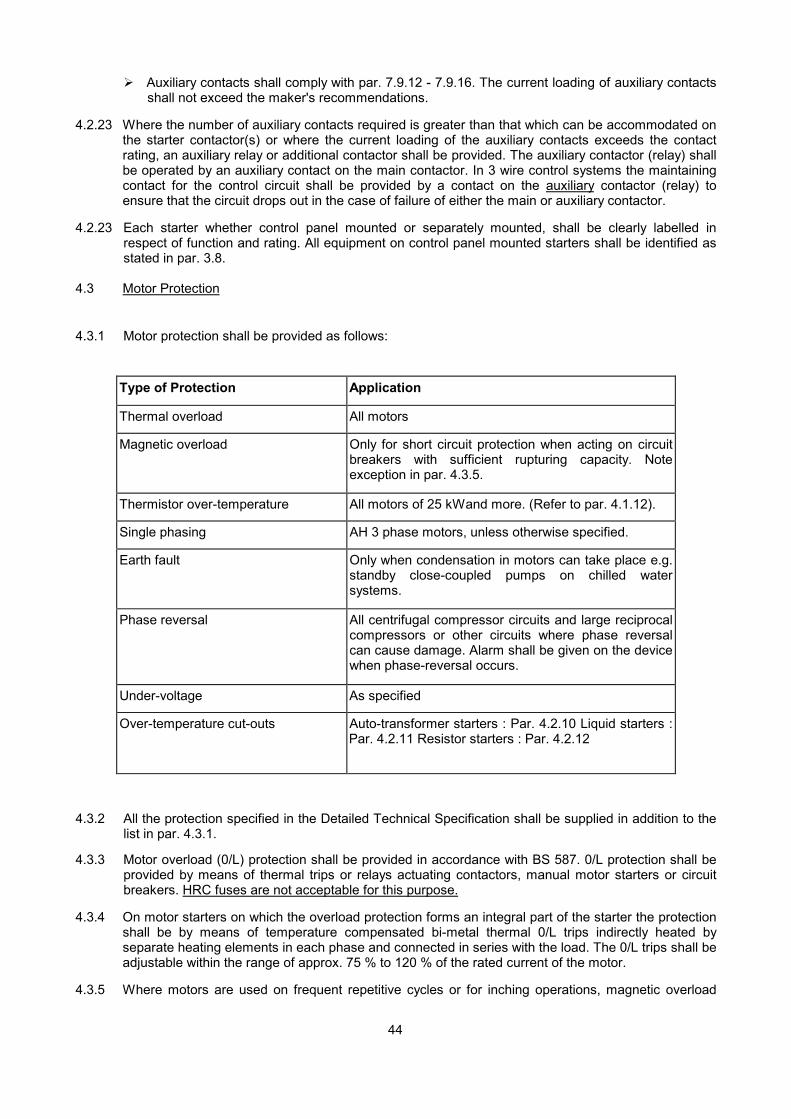
44
� Auxiliary contacts shall comply with par. 7.9.12 - 7.9.16. The current loading of auxiliary contactsshall not exceed the maker's recommendations.
4.2.23 Where the number of auxiliary contacts required is greater than that which can be accommodated onthe starter contactor(s) or where the current loading of the auxiliary contacts exceeds the contactrating, an auxiliary relay or additional contactor shall be provided. The auxiliary contactor (relay) shallbe operated by an auxiliary contact on the main contactor. In 3 wire control systems the maintainingcontact for the control circuit shall be provided by a contact on the auxiliary contactor (relay) toensure that the circuit drops out in the case of failure of either the main or auxiliary contactor.
4.2.23 Each starter whether control panel mounted or separately mounted, shall be clearly labelled inrespect of function and rating. All equipment on control panel mounted starters shall be identified asstated in par. 3.8.
4.3 Motor Protection
4.3.1 Motor protection shall be provided as follows:
Type of Protection Application
Thermal overload All motors
Magnetic overload Only for short circuit protection when acting on circuitbreakers with sufficient rupturing capacity. Noteexception in par. 4.3.5.
Thermistor over-temperature All motors of 25 kWand more. (Refer to par. 4.1.12).
Single phasing AH 3 phase motors, unless otherwise specified.
Earth fault Only when condensation in motors can take place e.g.standby close-coupled pumps on chilled watersystems.
Phase reversal All centrifugal compressor circuits and large reciprocalcompressors or other circuits where phase reversalcan cause damage. Alarm shall be given on the devicewhen phase-reversal occurs.
Under-voltage As specified
Over-temperature cut-outs Auto-transformer starters : Par. 4.2.10 Liquid starters :Par. 4.2.11 Resistor starters : Par. 4.2.12
4.3.2 All the protection specified in the Detailed Technical Specification shall be supplied in addition to thelist in par. 4.3.1.
4.3.3 Motor overload (0/L) protection shall be provided in accordance with BS 587. 0/L protection shall beprovided by means of thermal trips or relays actuating contactors, manual motor starters or circuitbreakers. HRC fuses are not acceptable for this purpose.
4.3.4 On motor starters on which the overload protection forms an integral part of the starter the protectionshall be by means of temperature compensated bi-metal thermal 0/L trips indirectly heated byseparate heating elements in each phase and connected in series with the load. The 0/L trips shall beadjustable within the range of approx. 75 % to 120 % of the rated current of the motor.
4.3.5 Where motors are used on frequent repetitive cycles or for inching operations, magnetic overload
45
protection with time delays may be used provided the motor is suitably rated for the duty (refer to par.4.1.4 above).
4.3.6 Single phasing protection where provided shall be inherent in the overload protection unit in the caseof Integral motor starters. Protection schemes depending solely on the excess current drawn by themotor during single phasing are not acceptable.
4.3.7 Magnetic over-current trips or relays for short circuit protection may never be allowed to actuatecontactor starters and may only operate on suitably rated circuit breakers.
4.3.8 Short circuit protection shall be provided by means of HRC fuses or suitably rated circuit breakers,(refer to Section 5).
4.3.9 As an alternative to a conventional circuit breaker and starter system having overload and singlephasing relays, a combination circuit protector which incorporates over-current, single phasing andshort circuit protection and which has adjustable current and time characteristics may be used inconjunction with a contactor. The type of protector shall be approved by the Department prior toinstallation.
4.3.10 Thermistor over-temperature protection shall be installed as described in par. 4.1.12-4.1.15. Thethermistor control units shall where possible be integrated with the motor starter. Care shall be takento select units with sufficient current rating to operate the contactor coil.
4.3.11 Thermistor protection may not be provided in lieu of overcurrent protection.
4.3.12 Electronic Motor protection relays with a thermal simulation system and with memory independent ofauxiliary power supplies shall be used. Different type relays shall be used for motors between 50 kWand 132 kW and for 132 kW and larger. In all cases the relay used shall be approved in writing by theDepartment prior to installation. The relay shall be mounted in such a manner that all indicators shallbe visible from outside the starter enclosure. The provisions of Clause 4.2.20 shall also apply.
Thermal (or magnetic if required) overload, single phasing (or phase unbalance) and earth faultprotection relays as well as auxiliary relays where specified, shall be included. The relays shall behoused in a panel-mounted unit in a withdrawable case.
4.3.13 Motor protection relays shall not be allowed to operate on metering current transformers but shall beconnected to separate Class 5P10 current transformer for relays for electronic protection and Class10P10 for other relays. In each case the output shall be suitable for the burden of the relays chosen.The current transformer ratio shall be matched to the motor full load current.
4.3.14 If called for in the Detailed Technical Specification, the electronic relays referred to in Clause 4.3.12shall, when tripped, provide a visual indication of the fault condition which caused tripping, e.g.overload, single phasing, locked rotor etc.
4.3.15 Where motors which are not described in BS Specifications e.g. semi-hermetic compressor motors,etc, are used, protection shall comply with the manufacturer's requirements.
4.3.16 Special attention shall be paid to motors driving high inertia loads to ensure that motors areadequately protected against sustained over-currents but do not trip unnecessarily during starting.
� Shorting of the over-current protection during starting is not acceptable.� Increased overload settings on protection units is not acceptable.� Connecting the overload relay in the delta loop in star-delta starting applications thus providing no
protection during starting, is not acceptable.� In all such cases electronic motor protection relays as covered by Clause 4.3.12 shall be
employed,irrespective of the motor power rating.
5. SHORT CIRCUIT PROTECTION
5.1 General
5.1.1 All circuits shall be adequately protected against short circuit conditions at any point in the circuit upto the maximum fault current that can occur.
46
5.1.2 Short circuit protection of circuits shall consist of circuit breakers with HRC fuse back-up protection.
5.1.3 Protection devices (circuit breakers and fuse gear) shall be adequately rated to break the maximumfault current that can occur at the point in the circuit at which the equipment is installed. The followingfactors shall be taken into account:
� The maximum symmetrical fault current (in A)� The supply voltage (400V, 3.3 kV. etc.)� The power factor during fault conditions
5.2 Determination of Fault Current
5.2.1 Where a supply connection is provided by others, it is the responsibility of the Mechanical Contractorto obtain the fault level from the Departmental the point where he receives the supply. The switchgearshall be rated accordingly.
5.2.2 Where the supply is obtained directly from a transformer, the fault level can be determined fromTable 5.1.
Table 5.1
Transformer Size(kVA)
PercentageImpendance
(%)
Fault level(MVA)
Fault Current (A)
400V 525V 3300V
10 4,5 0,22 321 244 •
16 4.5 0,36 513 391 -25 4.5 0,56 802 611 -50 4,5 1,11 1604 1222 -100 4,5 2..22 3208 2444 389200 4,5 4,44 6415 4888 778315 4.5 7,00 10104 7698 1225400 4,5 8,89 12830 9776 1555500 4,5 11,11 16038 12219 1944800 4.5 17,78 25661 19551 31101000 5.0 20,00 28868 21995 34991250 5,0 25,00 36085 27494 43741600 5,0 32,00 46189 35192 55992000 5,5 36,36 52488 39991 6362
5.3 Short Circuit Protection of Motors
5.3.1 The short circuit protection of motors shall consist of HRC fuses AND/OR suitably rated circuitbreakers with instantaneous magnetic trips subject to the following conditions:
Circuit breakers may be used for fault levels up to 5 kA.
Circuit breakers backed up by HRC fuses with a maximum current rating of 200 A may be used forfault levels up to 10 kA in cases where more than one motor circuit is supplied from the same set offuses. The rupturing capacity of the breaker shall comply with the requirements of par. 5.7.3.
HRC fuses shall be used in all cases where the fault level exceeds 10 kA.
Prospective fault levels at the input to the control board shall be used in the above considerations.(Refer also to par. 5.4.1).
5.3.2 Some of the implications of the previous paragraph are as follows:
HRC fuses may be used for short circuit protection of all motor circuits.
47
Contactors may NOT be used for short circuit protection.
5.3.3 The required fuse sizes and the setting of instantaneous magnetic trips on circuit breakers for theshort circuit protection of motor circuits based on average figures for full load current, power factorand efficiency are shown in Tables 5.2, 5.3 and 5.4.
5.3.4 Circuit breakers with fixed magnetic trips must be selected to comply as closely as possible with thevalues listed in Tables 5.2, 5.3 and 5.4. In the case of adjustable magnetic trips the values shall betaken as maximum values and shall be set lower if the starting characteristic of the motor and loadallows this without causing nuisance tripping.
5.3.5 If motor currents deviate significantly from the values stated below due to special constructions,suitable fuse ratings or circuit breaker settings shall be obtained from the supplier. In cases wherethe motor is subjected to long starting periods or frequent repetitive starting cycles, the fuse ratingsshall be matched to the motor duty.
5.3.6 Tables 5.2. 5.3 and 5.4 show typical fuse sizes as supplied by a manufacturer for standard type "T'fuses according to BS 88. If other fuse types are employed, the Contractor shall obtain the necessaryinformation from both the motor and fuse manufacturer to ensure that the fuse characteristics arematched to those of the motors.
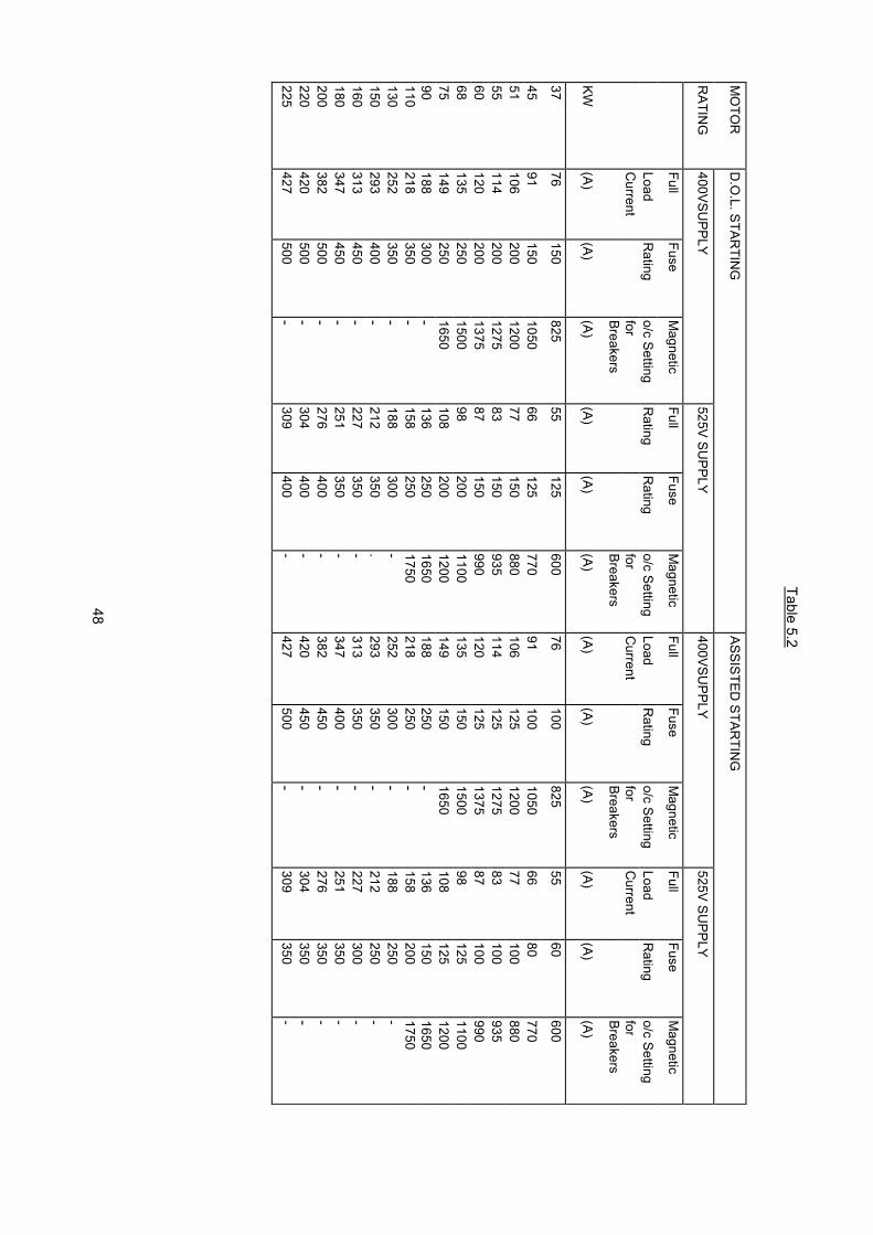
48
Table 5.2
MO
TOR
D.O
.L. STARTIN
GASSISTED
STARTIN
G
RATIN
G400VSU
PPLY525V SU
PPLY400VSU
PPLY525V SU
PPLY
FullFuse
Magnetic
FullFuse
Magnetic
FullFuse
Magnetic
FullFuse
Magnetic
LoadR
atingo/c Setting
Rating
Rating
o/c SettingLoad
Rating
o/c SettingLoad
Rating
o/c SettingC
urrentfor
forC
urrentfor
Current
forBreakers
BreakersBreakers
Breakers
KW(A)
(A)(A)
(A)(A)
(A)(A)
(A)(A)
(A)(A)
(A)
3776
150825
55125
60076
100825
5560
600
4591
1501050
66125
77091
1001050
6680
77051
106200
120077
150880
106125
120077
100880
55114
2001275
83150
935114
1251275
83100
93560
120200
137587
150990
120125
137587
100990
68135
2501500
98200
1100135
1501500
98125
110075
149250
1650108
2001200
149150
1650108
1251200
90188
300-
136250
1650188
250-
136150
1650110
218350
-158
2501750
218250
-158
2001750
130252
350-
188300
-252
300-
188250
-150
293400
-212
350.
293350
-212
250-
160313
450-
227350
-313
350-
227300
-180
347450
-251
350-
347400
-251
350-
200382
500-
276400
-382
450-
276350
-220
420500
-304
400-
420450
-304
350-
225427
500-
309400
-427
500-
309350
-

49
Table 5.3
MO
TOR
D.O
.L. STARTIN
GASSISTED
STARTIN
G
RATIN
G400VSU
PPLY525V SU
PPLY400VSU
PPLY525V SU
PPLY
FullFuse
Magnetic
FullFuse
Magnetic
FullFuse
Magnetic
FullFuse
Magnetic
LoadR
atingo/c Setting
Rating
Rating
o/c SettingLoad
Rating
o/c SettingLoad
Rating
o/c SettingC
urrentfor
forC
urrentfor
Current
forBreakers
BreakersBreakers
Breakers
KW(A)
(A)(A)
(A)(A)
(A)(A)
(A)(A)
(A)(A)
(A)
0,752,1
1030
1,56
302,1
430
1,52
30
1,12,7
1535
210
302,7
635
2,04
301,5
3,715
552,7
1535
3,76
552,7
635
2,25,3
2055
3,815
505,3
1555
3,810
353,0
7,020
905,1
1555
7,015
905,1
1055
4,09,4
25110
6,820
909,4
15110
6,815
905,5
12,635
1409,1
25110
12,620
1409,1
15110
7,515,8
40175
11,430
14015,8
25175
11,420
1409,0
18,940
22013,7
35165
18,930
22013,7
20165
11,023
60275
1740
22023
35275
1725
22015,0
3180
38522
50275
3140
38522
30275
18,538
80440
2860
33038
50440
2835
33022
45100
50033
80385
4560
50033
40385
2653
100660
3880
44053
60660
3850
44030
61125
70044
100500
6180
70044
60500
3368
125770
49100
55068
80770
4960
550

50
Table 5.4
MO
TOR
D.O
.L. STARTIN
GASSISTED
STARTIN
G
RATIN
G400V SU
PPLY525V SU
PPLY400V SU
PPLY525V SU
PPLY
FullFuse
Magnetic
FullFuse
Magnetic
FullFuse
Magnetic
FullFuse
Magnetic
LoadR
atingo/c Setting
Rating
Rating
o/cLoad
Rating
o/cLoad
Rating
o/cC
urrentfor
SettlingC
urrentSetting for
Current
SettingBreakers
forBreakers
forBreakers
(A)Breakers
kW(A)
(A)(A)
(A)(A)
(A)(A)
(A)(A)
(A)(A)
250476
600-
345450
-476
550-
345400
-270
511600
-370
450-
511550
-370
450-
280519
600-
376500
-519
550-
376450
-300
560650
-405
500-
560600
-405
450-
315587
650-
425500
-587
600-
425450
-375
696700
-504
600-
696700
-504
550-
400744
750-
539600
-744
750-
539600
-450
837850
-606
600-
837850
-606
650-
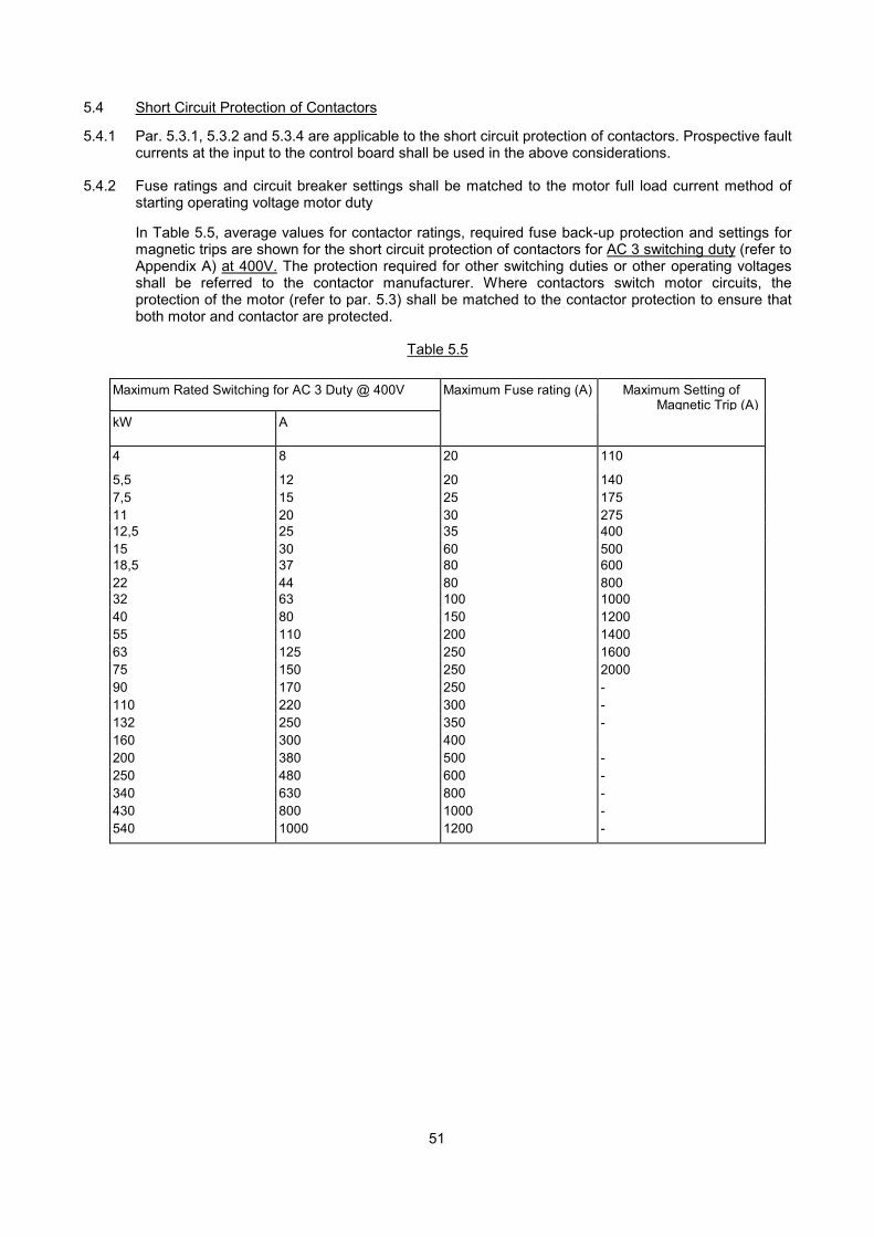
51
5.4 Short Circuit Protection of Contactors
5.4.1 Par. 5.3.1, 5.3.2 and 5.3.4 are applicable to the short circuit protection of contactors. Prospective faultcurrents at the input to the control board shall be used in the above considerations.
5.4.2 Fuse ratings and circuit breaker settings shall be matched to the motor full load current method ofstarting operating voltage motor duty
In Table 5.5, average values for contactor ratings, required fuse back-up protection and settings formagnetic trips are shown for the short circuit protection of contactors for AC 3 switching duty (refer toAppendix A) at 400V. The protection required for other switching duties or other operating voltagesshall be referred to the contactor manufacturer. Where contactors switch motor circuits, theprotection of the motor (refer to par. 5.3) shall be matched to the contactor protection to ensure thatboth motor and contactor are protected.
Table 5.5
Maximum Rated Switching for AC 3 Duty @ 400V Maximum Fuse rating (A) Maximum Setting ofMagnetic Trip (A)
kW A
4 8 20 110
5,5 12 20 1407,5 15 25 17511 20 30 27512,5 25 35 40015 30 60 50018,5 37 80 60022 44 80 80032 63 100 100040 80 150 120055 110 200 140063 125 250 160075 150 250 200090 170 250 -110 220 300 -132 250 350 -160 300 400200 380 500 -250 480 600 -340 630 800 -430 800 1000 -540 1000 1200 -

52
5.5 Short Circuit Protection of Overload Devices
5.5.1 Overload relays shall be protected against short circuits by means of fuses or circuit breakers withinstantaneous magnetic trips.
5.5.2 The short circuit protection for motors as stated in par. 5.3 will, in most cases, protect the overloaddevice if the device is properly matched to the motor. The Contractor shall verify that the overloadrelay is protected sufficiently by the motor short circuit protection.
5.6 Short Circuit Protection of Cables
The maximum fuse ratings or the maximum settings of instantaneous magnetic trips on circuitbreakers for the short circuit protection of cables are shown in Table 5.6 for multi-core PVC cableswith stranded copper conductors. The prospective fault current used shall be calculated at the supplyend of the cable.
Table 5.6
Cable Size(mm2)
Maximum Load Current(A)
Maximum Fuse rating (A) Maximum Setting of InstantaneousMagnetic Trip (kA)
1.5 12 50 0,4
2,5 17 60 0,564 23 100 0,956 30 150 1,510 46 200 2,016 61 250 3,025 81 300 5,435 99 500 8,050 125 600 1070 155 800 1495 185 1600 20120 215 - 27150 250 - 34185 280 - 42240 330 - 53300 380 - 70
5.7 Back-up Protection for Circuit Breakers
5.7.1 Where the maximum fault current exceeds the rupturing capacity of a circuit breaker which isrequired at a point in the electrical system, HRC fuses shall be installed in series with the circuitbreaker to provide back-up short circuit protection.
5.7.2 The Contractor shall match the characteristic curves of the fuses and circuit breakers to ensure thatadequate discrimination is provided between the two characteristics.
5.7.3 The required symmetrical RMS rupturing capacity of circuit breakers at 400V and a power factor of0,25 with back-up fuse protection is shown in table 5.7.
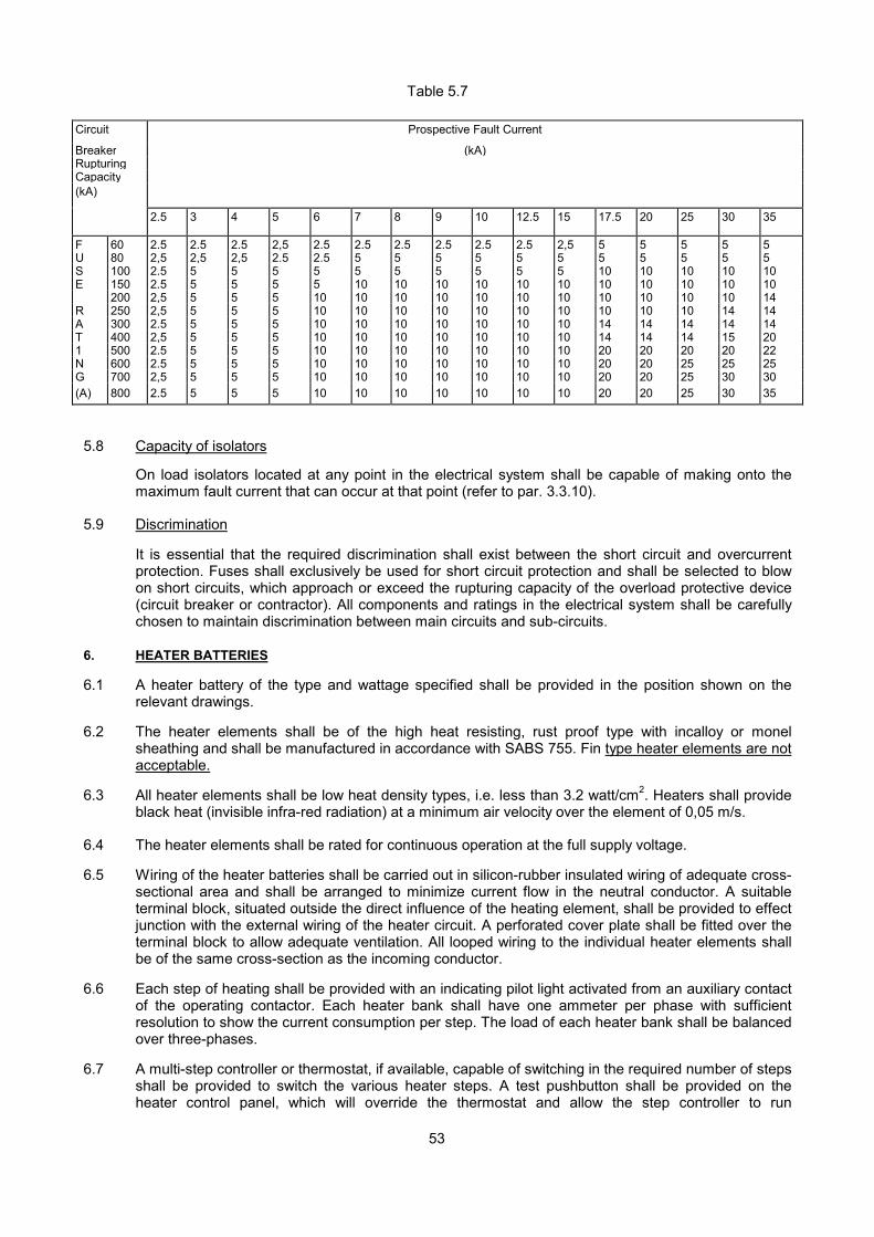
53
Table 5.7
Circuit Prospective Fault Current
Breaker (kA)RupturingCapacity(kA)
2.5 3 4 5 6 7 8 9 10 12.5 15 17.5 20 25 30 35
F 60 2.5 2.5 2.5 2,5 2.5 2.5 2.5 2.5 2.5 2.5 2,5 5 5 5 5 5U 80 2,5 2,5 2,5 2.5 2.5 5 5 5 5 5 5 5 5 5 5 5S 100 2.5 5 5 5 5 5 5 5 5 5 5 10 10 10 10 10E 150 2.5 5 5 5 5 10 10 10 10 10 10 10 10 10 10 10
200 2,5 5 5 5 10 10 10 10 10 10 10 10 10 10 10 14R 250 2,5 5 5 5 10 10 10 10 10 10 10 10 10 10 14 14A 300 2.5 5 5 5 10 10 10 10 10 10 10 14 14 14 14 14T 400 2,5 5 5 5 10 10 10 10 10 10 10 14 14 14 15 201 500 2.5 5 5 5 10 10 10 10 10 10 10 20 20 20 20 22N 600 2.5 5 5 5 10 10 10 10 10 10 10 20 20 25 25 25G 700 2,5 5 5 5 10 10 10 10 10 10 10 20 20 25 30 30(A) 800 2.5 5 5 5 10 10 10 10 10 10 10 20 20 25 30 35
5.8 Capacity of isolators
On load isolators located at any point in the electrical system shall be capable of making onto themaximum fault current that can occur at that point (refer to par. 3.3.10).
5.9 Discrimination
It is essential that the required discrimination shall exist between the short circuit and overcurrentprotection. Fuses shall exclusively be used for short circuit protection and shall be selected to blowon short circuits, which approach or exceed the rupturing capacity of the overload protective device(circuit breaker or contractor). All components and ratings in the electrical system shall be carefullychosen to maintain discrimination between main circuits and sub-circuits.
6. HEATER BATTERIES
6.1 A heater battery of the type and wattage specified shall be provided in the position shown on therelevant drawings.
6.2 The heater elements shall be of the high heat resisting, rust proof type with incalloy or monelsheathing and shall be manufactured in accordance with SABS 755. Fin type heater elements are notacceptable.
6.3 All heater elements shall be low heat density types, i.e. less than 3.2 watt/cm2. Heaters shall provideblack heat (invisible infra-red radiation) at a minimum air velocity over the element of 0,05 m/s.
6.4 The heater elements shall be rated for continuous operation at the full supply voltage.
6.5 Wiring of the heater batteries shall be carried out in silicon-rubber insulated wiring of adequate cross-sectional area and shall be arranged to minimize current flow in the neutral conductor. A suitableterminal block, situated outside the direct influence of the heating element, shall be provided to effectjunction with the external wiring of the heater circuit. A perforated cover plate shall be fitted over theterminal block to allow adequate ventilation. All looped wiring to the individual heater elements shallbe of the same cross-section as the incoming conductor.
6.6 Each step of heating shall be provided with an indicating pilot light activated from an auxiliary contactof the operating contactor. Each heater bank shall have one ammeter per phase with sufficientresolution to show the current consumption per step. The load of each heater bank shall be balancedover three-phases.
6.7 A multi-step controller or thermostat, if available, capable of switching in the required number of stepsshall be provided to switch the various heater steps. A test pushbutton shall be provided on theheater control panel, which will override the thermostat and allow the step controller to run
54
sequentially through the heater steps and back again for diagnostic purposes.
6.8 Each heater step shall be protected by a suitably rated moulded case circuit breaker (MCCB) withhigh rupturing current (HRC) fuse back-up protection where the maximum fault current on the boardexceeds the rupturing capacity of the MCCB. (Refer to par. 3.3.12 and 5.7).
6.9 A flow switch shall be provided to switch the heaters off when there is no air flow.
6.10 A high limit safety thermostat shall be provided to switch the heaters off in the case of over-temperature. A delay timer shall be provided which will keep the fan running for an adjustable periodafter switch-off to prevent the over-temperature thermostat from tripping.
6.11 The fan shall be timed to run for a minimum of 1 minute after the heaters have been turned off.
6.12 All doors of the air-conditioning or ventilation plenum chamber, providing access to the heaterbatteries. shall be fitted with microswitches to switch the heaters off when the doors are opened.
6.13 An interlock via a N/0 contact on the fan contactor shall be provided in order to switch off the heatersin case the fan contactor is switched off or trips.
6.14 A test pushbutton to test all pilot lights shall be provided.
6.15 Tenderers shall submit full details of the heaters offered with their tenders. Preference will be given tolocally manufactured standard production types for which spares are readily available.
7. SWITCHGEAR
7.1 Metal Clad Air Circuit Breaker, Withdrawable Type
7.1.1 The metal clad circuit breaker shall comply with the requirements laid down in BS 4752.
7.1.2 The circuit breaker shall be horizontally withdrawable and shall be a self contained unit of the deadfront type, allowing maintenance and tests to be carried out without having to remove the circuitbreaker from the withdrawal mechanism. The unit shall contain the necessary mechanical interlocksto prevent:
Access to "Live" terminals when the breaker is withdrawn.
The withdrawal or insertion of the unit, when the breaker is in the closed position.
Closing of the circuit breaker following an automatic trip condition without resetting the mechanism.
7.1.3 Adjustable thermal overload releases shall be provided to suit the required current range. In addition,instantaneous magnetic short circuit trips, which are adjustable, shall be fitted. The tripping devicesshall be direct acting. This delay adjustment shall be bypassed with an instantaneous making currentrelease when the circuit breaker is closed to prevent the delay timer from operating when the circuitbreaker is closed on a fault.
7.1.4 The tripping time characteristics of the circuit breaker shall be such that good grading can beobtained between the main incoming circuit breaker and the switchgear on the outgoing circuits,under overload and short circuit conditions. High-speed current limiting type air circuit breakers willnot be acceptable.
7.1.5 The air circuit breaker shall be of the quick-make and quick-break type with a stored-energy springassisted operating mechanism provided with:
A trip free mechanical hand operated closing mechanism. A manually operated mechanical tripmechanism suitably protected to prevent inadvertent tripping.
A positively driven mechanical device to provide ON/OFF/TRIP indication. This indication shall beclearly visible with the circuit breaker in position.

55
7.1.6 Provision shall exist for the addition, if specified, of a source-side under-voltage lock-out.
7.1.7 Circuit breakers shall have electrically separate auxiliary contacts as specified. Where none arespecified two N/0 and two N/C auxiliary contacts shall be provided. Shunt trips and electrical storedenergy breakers shall be interlocked to prevent repeated operation (hunting) of the trips or windingmechanisms when the breaker is in the tripped or closed position.
7.1.8 All non-current carrying metal parts of the circuit breaker shall be solidly interconnected andconnected to an earth contact which shall engage with a mating contact or copper plate which isconnected to the earth busbar of the switchboard. The arrangement shall be such that the circuitbreaker frame is earthed in the test position and before the breaker contacts engage the live fixedcontacts.
7.1.9 The fixed cradle shall be of high mechanical strength.
7.1.10 The circuit breaker shall have RACKED-OUT. TEST and ENGAGED positions which shall be clearlymarked.
7.1.11 The circuit breaker shall bear a clearly legible rating plate indicating the current rating, breakingcapacity and voltage rating.
7.1.11 Extension type operating handles shall be fixed to the circuit breaker on completion of the installation.
7.1.13 The circuit breaker shall be designed to allow the incoming terminals to be at the top or bottom withoutaffecting the operation of the unit.
7.1.14 The circuit breakers shall be derated as necessary to compensate for the following environmentalfactors:
Maximum ambient air temperature in excess of 40°C or the daily average ambient air temperature inexcess of 30°C. This is especially important with regard to the type of enclosure in which the circuitbreaker is to be installed.
Height above sea level. Operational duty cycle and estimated loading.
7.1.15 The complete circuit breaker and its electrical and mechanical constituents and accessories must bea standard product of a single original manufacturer.
7.2 Moulded Case Circuit Breaker
7.2.1 The circuit breaker shall be of the single pole or multipole free handle, air break type, housed in amoulded phenolic or glass polyester case and suitable for panel mounting.
7.2.2 The circuit breaker shall comply with the requirements of SABS 156.
7.2.3 Circuit breakers shall be suitable for operation on supply voltages of 380/230V to 440/250 V, 50 Hzand the rupturing capacity at these voltages, when the circuit breakers are tested in accordance withClause 7.10 of SABS 156. shall be as specified in the Detailed Technical Specification.
7.2.4 The overload and short circuit trips of the circuit breaker may be of the following type to suit theapplication:
Combined thermal/magnetic trips with interchangeable trip units, the magnetic trip setting beingadjustable.
Combined thermal-magnetic trips with fixed and sealed trip units, the magnetic trip setting beingadjustable.
Combined thermal/magnetic trips with fixed and non-adjustable trip units.
Hydraulic/magnetic trips with fixed and non-adjustable trip units.
Solid state controlled trips with interchangeable fixed rating plugs for overload tripping and adjustablemagnetic trip settings incorporating a short time delay.

56
Solid state controlled trips with interchangeable adjustable rating plugs for overload tripping andadjustable magnetic trip settings incorporating a short time delay.
7.2.5 The tripping times of the circuit breakers shall be in accordance with Clause 4.5 of SABS 156.
7.2.6 The circuit breaker contacts shall be of silver alloy, and arc chutes or magnetic blow-outs shall beprovided. The contacts shall close with a high pressure wiping action.
7.2.7 The incoming terminals of single pole miniature circuit breakers shall be suitable for connection to acommon busbar. Ganged toggles for circuit breakers will be acceptable, provided that the tripmechanisms are internally linked.
7.2.8 Where specified, the circuit breaker shall be suited to accommodating factory fitted shunt trip orauxiliary contact units or similar equipment.
7.2.9 The operating handle shall provide clear indication on ON, OFF and TRIP positions.
7.2.10 The mechanism shall be of the TRIP-FREE type preventing the unit from being held in the ONposition under overload conditions.
7.2.11 Circuit breakers used on any one particular service shall be supplied by a single manufacturer.
7.2.12 The continuous current rating, voltage rating and rupturing capacity of the circuit breaker shall be asrequired by the equipment and the circuit breaker shall have a rating plate indicating the currentrating, voltage rating and rupturing capacity.
7.2.13 Extension type operating handles shall be provided for units of 600 A rating and above.
7.3 Earth leakage Relays
7.3.1 Single-phase or three-phase earth leakage relays with associated double or triple pole circuitbreakers shall be supplied and installed on all circuits feeding socket outlets and other general powercircuits in compliance with the Code of Practice for the Wiring of Premises. SABS 0142.
7.3.2 The relays shall operate on the core balance (current balance) principle. The operation shall beindependent of mains voltage and shall function with any of the supply conductors (and neutral)disconnected or broken.
7.3.3 The sensitivity and operating response of the relay must be such that instantaneous tripping willoccur at a total earth leakage current of 20 mA. The unit shall have compensation for ambienttemperature variations and the sensitivity and operating response time must be maintained over therange of normal frequency variations. Stability of operation, long life and stability of characteristics areessential.
7.3.4 The unit shall be provided with integral test facilities by means of which the correct functioning of theunit may be tested.
7.3.5 The unit shall withstand fault currents of 2,5 kA or 5 kA as specified either between phase and earth,or between phase and neutral, without any damage being caused thereby.
7.3.6 The circuit breaker associated with the earth leakage unit shall be of the double pole (for single-phase circuits) and triple pole (for three-phase circuits), free handle type, having a rupturing capacityof not less than 2,5 kA . The circuit breaker shall be fitted with a release tripping mechanism andmust match with the earth leakage unit.
7.3.7 The circuit breaker and earth leakage relay shall be suitable for operation on a 220/250 V. 50 Hzsupply on single-phase circuits and 380/440 V. 50 Hz supply on three-phase circuits.
7.3.8 The earth leakage unit shall comply fully with SABS 767.
7.3.9 Where specified for wall mounting, the circuit breaker and earth leakage relay shall be mounted in asubstantial sheet metal case with anti-corrosion treatment and baked enamel finish.

57
7.4 On-Load. Fault-making Switches
7.4.1 On-load, fault-making switches shall be of the triple pole, hand operated, panel mounting, air-breaktype suitable for operation on 380/440 V, 50 Hz systems.
7.4.2 The contacts shall be of silver alloy and the switch mechanism shall be of the quick-make, quick-break type.
7.4.3 The switches shall be capable of opening and closing the full current rating of the switch. The currentrating of the switch shall be in excess of the full load current of the circuit, which the switch will berequired to open. In the case of motor circuits the switch shall be capable of breaking the "lockedrotor current" of the motor.
7.4.4 The switches shall further be capable of being closed on to a fault. The switches shall be adequatelyrated to withstand the maximum fault current that can occur at that point in the circuit for a sufficienttime to allow the back-up protection (circuit breakers or fuses) to open the circuit.
7.4.5 The switches shall be suitable for mounting behind switchboard panels.
7.4.6 To distinguish the switches from circuit breakers, the operating handle shall have a distinctive colouror other clear indelible indication and shall be clearly labelled "ISOLATOR".
7.5 Rotary Switches
7.5.1 The switches shall be of the cam actuated or wiping air break type with two breaks per pole, therequired number of poles and number of functions being provided by the assembly of switch units ona common spindle. Unless specified to the contrary the switches shall be constructed for mountingbehind a flush panel, and shall be provided with a suitable faceplate and operating handle.
7.5.2 The contacts shall be of silver alloy and the latching mechanism shall ensure positive accuratepositioning of the handle in relation to faceplate markings. The voltage and current ratings shall be asrequired by the circuit and control function and the making capacity shall be at least three times thenormal current rating.
7.5.3 Special contacts, e.g. late-making, early-breaking, etc. shall be inherent in the design and shall not beimprovised by loading, re-shaping or bending of contacts.
7.6 Microgap Switches
7.6.1 The switches shall be of the double pole or triple pole (as required) microgap type, for use on AConly. Triple pole switches shall be rated for continuous operation for supply voltages up to 500 V anddouble pole switches for voltages up to 250 V.
7.6.2 Heavy brass terminals each with two grub screws, shall be provided for incoming and outgoingcables and the terminals shall be arranged for easy wiring.
7.6.3 The switch shall have solid silver contacts with large contact surfaces capable of carrying, makingand breaking its rated current.
7.6.4 The "ON" and "OFF" positions of the switch shall be clearly marked.
7.6.5 The switches shall comply fully with the requirements of SABS 152.
7.7 Combination Fuse Switch Units
7.7.1 The fuse switch shall be of the triple pole type in accordance with BS 5419.
7.7.2 The fuse cartridges shall comply with SABS IEC 269. suitable for a 415 V 50 Hz system. Category ofduty shall be matched to the fault level at the point where the fuses are installed.
7.7.3 The fuse switch shall have a hand operated lever and the "ON" and "OFF" positions shall be clearly
58
marked.
7.7.4 Fuse switch units shall be of the double air-break, quick-make, quick-break type and shall have aspring mechanism smoothly driven by springs on both sides of the mechanism. Fusegear comprisingHRC fuse cartridges carried on the cover, the cover also forming the operating lever, is regarded as afuse isolator and is not acceptable.
7.7.5 The fuse links must be fully isolated when the switch is in the "OFF" position and interlocks must beprovided to prevent the cover being opened when the switch is closed and to prevent the switch beingoperated with the cover open.
7.8 Fuses and Fuse Holders
7.8.1 High rupturing capacity (HRC) fuses shall comply with the requirements of SABS 172 with a fusingfactor of 1.5.
7.8.2 Fuses which are not mounted integrally with switches, shall be mounted on insulated draw-outcarriers (holders) which hold the fuses positively after withdrawal. Fuse holders shall comply withSABS 173.
7.8.3 Each fuse link and holder shall incorporate an effective visual inspection eye for fault location.
7.8.4 Should live terminals become exposed after the withdrawal of fuses, rigid barriers shall be providedbetween adjacent sets of terminals to prevent accidental contact during withdrawal or insertion of thefuses.
7.8.5 Control circuits shall be protected by suitably rated fuses. Instrument fuses shall be mounted in closeproximity to the relevant instrument. These fuses shall be clearly labelled with engraved plastic orivory sandwich strips indicating use. rating and duty (where applicable).
7.8.6 Striker pin fuses shall be equipped with an alarm contact so arranged that the contact closes andremains closed when the striker pin operates.
7.8.7 Fuses shall be so connected that the live terminal is at the top.
7.8.8 Fuse ratings shall be accurate to within 5 % of the published value for unused fuses and shall notvary significantly after long periods of service.
7.8.9 Fuses shall be derated for ambient temperatures above 25°C in accordance with the manufacturer'srecommendation. If no such recommendation exists, a derating factor of 1 % per °C above 25°C shallbe applied.
7.8.10 Fuses shall be derated for elevations of more than 1 000 m above sea level in accordance with themanufacturers recommendation. If no such recommendation exists, a derating factor of 1% per300m above 1 000m above sea level shall be applied.
7.8.11 Time/current characteristics shall be chosen to suit the application.
Cable protection The fusing factor shall not exceed 1,5.
Motor circuits Time-lag characteristic shall be such that the startingcurrents will not cause deterioration of the fuse.
Capacitor circuits Fuses shall be chosen to withstand a higher than normalfull-load current (1,5 times rated capacitor current) toallow for harmonics and shall not deteriorate due to thehigh transients at switch-on
Distribution systems The total operating Ft let through by secondary (minor)fuses shall be less than that of primary (major) fuses inany specific branch.
7.8.12 It shall be ensured that the rupturing capacity of a fuse chosen for a specific application shall be
59
adequate both as far as short circuit current and applied voltage are concerned.
7.9 Contactors
7.9.1 Contactors shall be of the open or totally enclosed, double or triple pole, electro-mechanicallyoperated air-break type suitable for 220/250 V or 380/440 V supplies and shall comply with SABS1092.
7.9.2 Contactors shall have the following characteristics:
� Enclosed coil easily replaceable.� a permanent air gap in the magnetic circuit to prevent sticky operation,� provision for quick and simple inspection of contacts.� clearly marked main and auxiliary terminals, and� all parts accessible from the front.
7.9.3 Contactors, which are not located in switchboards, shall be housed in enclosures, which comply withpar. 4.2.20.
7.9.4 The current rating of the contactor shall be as specified for the circuit with a switching duty inaccordance with the IEC Publication 158-1. utilization category AC1 for lighting and power circuitsand utilization category ACS for motor starting.
7.9.5 The mechanical duty of the contactor shall comply with the specified requirements of BS 5424.
7.9.6 In addition to the required current carrying capacity and switching duty of a contactor, the contactorchosen for a particular application shall be rated for the maximum through fault current allowed by theback-up protection devices at the point where the contactor is installed. Careful co-ordination of shortcircuit devices shall be applied.
7.9.7 All laminations of the magnetic system of the contactor shall be tightly clamped. Noisy contactors willnot be accepted.
7.9.8 Non-current carrying metallic parts shall be solidly interconnected and a common screwed earthterminal shall be provided. The contactor shall be earthed to the switchboard earth bar.
7.9.9 Latched contactors shall be provided with a trip coil and a closing coil. The contactor shall remainclosed after energizing the closing coil and shall only trip on energizing the trip coil.
7.9.10 Contactor operating coils shall have a voltage rating as required by the control circuitry and shall havethe limits of operation and temperature rise as specified in IEC Publication 158-1. Latched contactorsshall be capable of being tripped at 50 % of the rated coil voltage.
7.9.11 Contactors for normal/standby change-over circuits shall be electrically and mechanically interlocked.Contactors shall also be electrically and mechanically interlocked in certain star-delta starters asspecified in par. 4.2.9.
7.9.12 Contactors with provision for adding auxiliary contacts on site are required. Contactors withpermanently fixed auxiliary contacts shall have at least 1 x N/0 and 1 x N/C spare auxiliary contacts inaddition to contacts specified for control purposes and in addition to contacts required for self-holdingoperations or economy resistances. (Refer to par. 4.2.22 and 4.2.23). Where the number of auxiliarycontacts required is greater than the contacts that can be accommodated on the contactor, anauxiliary relay or additional contactor shall be provided to supply the additional contacts. (Refer topar. 4.2.23.)
7.9.13 It shall be possible to replace main contacts without disconnecting wiring.
7.9.14 Auxiliary contacts shall be capable of making, carrying continuously and breaking 6 A at 230V ACand unity power factor.
7.9.15 Auxiliary contact functions required e.g. "lazy" contacts, late-make, late-break, make-before-breaketc. shall be inherent in the contact design. Under no circumstances may these functions beimprovised by loading, bending or re-shaping of contacts. These functions shall be available in allcontactors.

60
7.9.16 Spare auxiliary contacts shall be wired to numbered terminal strips in the switchboard and shallappear on the switchboard drawings.
7.9.17 All contactors on a specific project shall be from a standard range of one single reputablemanufacturer, unless specified to the contrary.
7.10 Indoor Lightning Arresters
7.10.1 Lightning arresters shall be of the single pole indoor type suitable for mounting on a meter box orswitchboard and suitable for the protection of domestic electrical appliances.
7.10.2 The arresters shall be of the valve type. consisting of a sparkgap in series with a non-linearresistance, mounted in a housing of insulating material.
7.10.3 The arresters shall be suitable for installation at altitudes of up to 1 800 m above sea level.
7.10.4 In case of damage caused by very severe overloads, the arrester shall be automatically disconnectedfrom the mains and a visual indication given to show that the arrester has been disconnected.
7.10.5 The arresters shall be suitable for systems with grounded neutral and voltages up to 250 V to earth,and shall comply with the requirements of SABS 171 or VDE 0675.
7.10.6 Lightning arresters shall be provided only where specified in the Detail Technical Specification butshall always be provided where the electrical connection to the installation is taken from an overheadline.
8. CONTROL EQUIPMENT
8.1 Voltmeter Selector Switch
8.1.1 Voltmeter selector switches shall be rated for the system voltage and shall be suitable for use inconjunction with a voltmeter.
8.1.2 The switch shall have an "OFF" and three metering positions and provide readings between neutraland each of the three-phases. The contacts shall be break-before-make types.
8.1.3 The switch shall be suitable for vertical panel mounting with studs for back of panel connections. Theswitch shall be provided with a suitable face plate and operating handle, and shall be of the camactuated or wiping air break type with two breaks per pole.
8.1.4 The contacts shall be of silver alloy, and the latching mechanism shall ensure positive accuratepositioning of the knob in relation to the face plate markings. The terminals shall be clearly markedand arranged to facilitate wiring.
8.2 Voltmeter Fuses
8.2.1 The fuse shall consist of porcelain or other approved base suitable for panel mounting, a fuse carrier.and a cartridge type HRC fuse link.
8.2.2 The cartridges shall be for a nominal current rating of 1 A at 400V 50 Hz.
8.2.3 The fuses shall generally be in accordance with SABS I EC 269 for fuses of the AC 16 or AC 33category of duty whichever is applicable. For higher system fault levels back-up fuses with therequired rupturing capacity shall be provided.
8.2.4 The installation of voltmeter fuses shall comply with par. 3.5.4 and 7.8.5. 8.3
Ammeter Selector Switches
8.3.1 Three ammeters shall always be provided where all three-phase currents must be monitored unlessclearly specified to the contrary. A single ammeter with selector switch is not acceptable.
61
8.3.2 Where ammeter selector switches are specified, they shall comply with the requirements of par. 8.1except that they shall be make-before-break types. The wiring shall be arranged so that the currenttransformer terminals are short-circuited when the ammeter is not connected across them.
8.4 Control Selector Switches
All other selector switches specified, e.g. control by-pass switches, shall provide the requiredswitching functions and shall comply with the requirements of par. 7.5 and 8.1 .Rotary switches shallhave roll and wipe contacts to ensure low resistance. Rocker-arm or toggle switches shall havebifurcated contacts.
8.5. Pushbuttons
8.5.1 Pushbuttons and pushbutton arrangements may be used in switchboards and control boards or inself-contained units for control functions.
8.5.2 Pushbuttons and pushbutton assemblies for one specific project shall be supplied from a singlereputable supplier's product range.
8.5.3 The various types of pushbuttons employed shall be specifically selected for the required duty andmounting characteristics e.g. flush mounted, enclosed, self-contained, illuminated, etc.
8.5.4 All pushbuttons on a specific switchboard shall be of the same physical dimension (round or square)and shall be fully interchangeable as far as possible. Pushbuttons shall preferably be interchangeablewith indicator lamps, key switches, etc. in mounting dimensions.
8.5.5 Pushbuttons shall be designed for long life, low contact bounce and constant contact resistance.Mechanisms may be of the mechanical type with spring control and a clutch or catch frame or of thesolid state type operating on the principle of a non-contacting, inductive proximity switch.
8.5.6 All pushbuttons shall be provided with replaceable lenses with a variety of symbols. Legend platesshall be interchangeable.
8.5.7 Pushbutton terminals shall be suitable for the application with regard to spacing, conductor capacityetc. Screw type. soldered or connector type terminals shall be chosen to suit the specific applicationwith regard to good contact, ease of removal or alteration, rigidity, etc. Terminals shall be suitable forconductor sizes to be used. Pushbutton assemblies mounted on doors of control boards shall beenclosed to prevent inadvertent contact with the terminals.
8.5.8 Pushbuttons shall be suitable for the environmental conditions to be encountered, e.g. moisture.excessive temperatures, mechanical shock, vibration, etc.
8.5.9 Contact duty shall be chosen to suit the application. Wiping contacts shall be used for low voltagesand currents and snap-action contacts for high voltages and currents. Contacts shall be constructedof high quality material such as silver-tipped or gold laminated contacts.
8.5.10 Illuminated pushbuttons may employ neon. incandescent or LED lamps. Lamp voltages shall suitsystem control voltages. Lamps shall be derated when used for continuous duty. e.g. using 20 Vsupply on 28 V rated lamps. External resistors shall be used with LED lamps to avoid excessivecurrent.
8.5.11 Pushbuttons may be grouped together in purpose-made stations, suitable for the environment inwhich they are to be installed.
8.5.12 Keylock pushbuttons shall be supplied with duplicate keys. The removal action of the key shall suitthe application.
8.5.13 Where test pushbuttons are provided, these shall be of the self-cancelling type.
8.5.14 Pushbuttons shall comply with the applicable requirements of BS 4794, BS 3955 or VDE 0660.
8.5.15 The following are the colours for pushbuttons
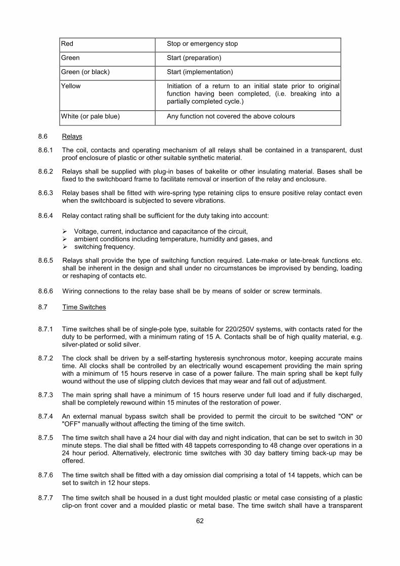
62
Red Stop or emergency stop
Green Start (preparation)
Green (or black) Start (implementation)
Yellow Initiation of a return to an initial state prior to originalfunction having been completed, (i.e. breaking into apartially completed cycle.)
White (or pale blue) Any function not covered the above colours
8.6 Relays
8.6.1 The coil, contacts and operating mechanism of all relays shall be contained in a transparent, dustproof enclosure of plastic or other suitable synthetic material.
8.6.2 Relays shall be supplied with plug-in bases of bakelite or other insulating material. Bases shall befixed to the switchboard frame to facilitate removal or insertion of the relay and enclosure.
8.6.3 Relay bases shall be fitted with wire-spring type retaining clips to ensure positive relay contact evenwhen the switchboard is subjected to severe vibrations.
8.6.4 Relay contact rating shall be sufficient for the duty taking into account:
� Voltage, current, inductance and capacitance of the circuit,� ambient conditions including temperature, humidity and gases, and� switching frequency.
8.6.5 Relays shall provide the type of switching function required. Late-make or late-break functions etc.shall be inherent in the design and shall under no circumstances be improvised by bending, loadingor reshaping of contacts etc.
8.6.6 Wiring connections to the relay base shall be by means of solder or screw terminals.
8.7 Time Switches
8.7.1 Time switches shall be of single-pole type, suitable for 220/250V systems, with contacts rated for theduty to be performed, with a minimum rating of 15 A. Contacts shall be of high quality material, e.g.silver-plated or solid silver.
8.7.2 The clock shall be driven by a self-starting hysteresis synchronous motor, keeping accurate mainstime. All clocks shall be controlled by an electrically wound escapement providing the main springwith a minimum of 15 hours reserve in case of a power failure. The main spring shall be kept fullywound without the use of slipping clutch devices that may wear and fall out of adjustment.
8.7.3 The main spring shall have a minimum of 15 hours reserve under full load and if fully discharged,shall be completely rewound within 15 minutes of the restoration of power.
8.7.4 An external manual bypass switch shall be provided to permit the circuit to be switched "ON" or"OFF" manually without affecting the timing of the time switch.
8.7.5 The time switch shall have a 24 hour dial with day and night indication, that can be set to switch in 30minute steps. The dial shall be fitted with 48 tappets corresponding to 48 change over operations in a24 hour period. Alternatively, electronic time switches with 30 day battery timing back-up may beoffered.
8.7.6 The time switch shall be fitted with a day omission dial comprising a total of 14 tappets, which can beset to switch in 12 hour steps.
8.7.7 The time switch shall be housed in a dust tight moulded plastic or metal case consisting of a plasticclip-on front cover and a moulded plastic or metal base. The time switch shall have a transparent
63
face to enable an operator to determine the time and settings without having to remove any covers.Time switches to be used for surface mounting on walls shall be provided with a suitably positioned20 mm conduit knock-out.
8.8 Sequence Time Switches
8.8.1 Sequence time switches suitable for starting a group of machines in a predetermined sequence, shallbe provided as required. The switches shall provide the number of steps indicated and minimum timeintervals of 15 seconds between starts.
8.8.2 Sequence time switches shall have normally open contacts unless specified to the contrary. Thecontacts shall be of silver-to-silver or other approved type with a minimum rating of 10 A.
8.8.3 Sequence time switches shall be of the reversible type, i.e. switching the machines on in the requiredsequence when rotating forward and switching the machines off in the reverse sequence whenrotating backwards.
8.8.4 Sequence time switches or time-delay switches shall be provided to prevent the simultaneousstarting of major or multiple items of equipment. The sequence shall not be reversible.
8.8.5 The switches shall be constructed so that the driving motor of the unit shall switch off when forwardrotation is complete while the controlled machines run on uninterrupted. When the machinery is to beswitched off, the drive motor on the unit shall rotate backwards and switch the machinery off in thereverse sequence. An ON/OFF switch shall control the sequence time switch from a remote position,where "ON" denotes the starting sequence and "OFF" denotes the stopping sequence. Switchpositions shall be indelibly labelled.
8.8.6 The switches shall return automatically to the start-up position when a power failure occurs.
8.8.7 The switches shall be suitable for operation at the system voltage.
8.8.8 Sequence time switches controlled by an electronic control unit providing the above functions, areacceptable.
9. INSTRUMENTATION
9.1 General
9.1.1 The following instrumentation shall be provided:
Ammeters on starters as described in par. 4.2.21;
Pilot lights and ammeters as described in par. 6.6 and 3.3.12;
On the incoming panels for switchboards with a rating of 150 A and more the following shall beprovided
(i) A voltmeter(ii) A voltmeter selector switch (refer par. 8.1)(iii) Three ammeters (refer par. 8.3). Maximum Demand Ammeters need only be provided when
specified in the Detail Technical Specification.
Electrically driven running hour meters on all stand-by mechanical equipment such as primary andstandby pumps and on refrigeration compressors with a motor size of 12 kW and more;
A pilot light. 25 mm minimum diameter, located at the switch to plenum chamber lights.
9.1.2 All other instrumentation as specified in the Detail Technical Specification shall be provided.
9.1.3 All instrumentation shall be clearly and adequately label led in both English and a local spokenlanguage, as approved by the Department's Representative, indicating purpose, e.g.
64
INCOMING SUPPLY VOLTAGEINKOMENDE TOEVOERSPANNING
RUNNING HOUR METER FOR COMPRESSOR NO. 2.LOPENDE UURMETER VIR KOMPRESSOR NR. 2.
9.2 Voltmeters
9.2.1 Voltmeters shall be of the moving iron type with Class 1,5 accuracy as specified in IEC 51 and shallbe suitable for flush mounting on vertical switchboard panels and shall be provided with studs for rearconnection. The terminals of voltmeters mounted on hinged front panels shall be shrouded orcovered to prevent accidental contact when the panels are open.
9.2.2 Voltmeters shall be of 72 mm or 96 mm square pattern unless specified to the contrary. Voltmeters,ammeters, frequency meters, etc. shall all have the same dimensions for any particular application.
9.2.3 Voltmeters shall be suitable for operation on a 50 Hz system and shall be manufactured inaccordance with the requirements of IEC 51 for industrial grade accuracy. The voltmeters shall becalibrated 0-300 V and shall withstand a test voltage of 2 kV.
9.2.4 Voltmeters shall be fitted with zero adjustment screws.
9.2.5 Voltmeters shall be screened to prevent magnetic interference and shall be fitted with anti-staticglass.
9.2.6 Voltmeters shall be approved by the Department before installation especially voltmeters required foraggressive atmospheres.
9.2.7 Voltmeters shall be protected by HRC fuses (refer to par. 3.5.49 7.8.5 and 8.2). Voltmeter selectorswitches shall comply with the requirements of par. 8.1
9.2.8 The wiring of voltmeters shall comply with the requirements of par. 3.5.3.
9.2.9 Each voltmeter shall be marked to indicate the appropriate phase to which it is connected. Where 3voltmeters are provided, they shall be installed in a horizontal line. The voltage which is beingmeasured shall be clearly marked in both English and a local spoken languages, as approved by theDepartments Representative, for example:
INCOMING SUPPLY VOLTAGEINKOMENDE TOEVOERSPANNING
SECONDARY VOLTAGE REGULATOR, ETC.KONDêRE SPANNINGSREGULEERDER. ENS.
9.2.10 Where voltmeters are connected to potential transformers, the ratio of the potential transformer shallbe marked on the voltmeter faceplate.
9.2.11 Voltmeters shall be suitable for the environment in which they are installed.
9.3 Ammeters
9.3.1 Ammeters shall be of the moving iron type suitable for flush mounting on vertical switchboard panelsand shall be provided with studs for rear connection. The terminals of ammeters mounted on hingedfront panels shall be shrouded or covered to prevent accidental contact when the panels are open.
9.3.2 Ammeters shall be of 72 mm or 96 mm square pattern unless specified to the contrary. Voltmeters,ammeters, frequency meters, etc. shall have the same dimensions.
9.3.3 Ammeters shall be suitable for operation on a 50 Hz AC system and manufactured to therequirements of IEC 51 with accuracy which need not exceed 1,5%. Current transformer operatedammeters shall be used for motors of 3 kW and larger. All current transformer operated ammetersshall be 5 A full scale calibrated to read actual primary circuit currents. The current transformer ratio

65
shall be indicated on the scale. Full load ratings shall be indicated by a red line. Ammeters shallwithstand a test voltage of 2 kV between the terminals and the housing or earth.
9.3.4 Where the calibration and current transformers are not specified, the ammeters shall be calibratedfor a full-scale deflection of approximately 110 % of the rated current of the circuit with matchingcurrent transformers. Ammeters used in motor circuits shall cater for motor starting current bycondensed over-scales up to 100 % overload scaling.
9.3.5 Ammeters shall be fitted with zero adjustment screws.
9.3.6 Ammeters shall be screened to prevent magnetic interference and shall be fitted with anti-staticglass.
9.3.7 Ammeters shall be approved by the Department prior to installation, especially ammeters required inaggressive atmospheres.
9.3.8 Three ammeters shall be provided on three-phase circuits, except as stated in par. 4.2.22. Oneammeter and an ammeter selector switch are not acceptable.
9.3.9 Each ammeter shall be marked to indicate the appropriate phase to which it is connected. Wherethree ammeters are provided they shall be installed in a horizontal line. Labels shall be fitted toindicate the specific circuit current being measured.
9.3.10 Ammeters shall be suitable for the environment in which they are installed.
9.4 Maximum Demand Ammeters
9.4.1 Maximum demand ammeters shall be provided if specified In the Detailed Technical Specification.
9.4.2 Maximum demand ammeters shall comply with the requirements of par. 9.3 except that in addition tothe moving Iron ammeters showing instantaneous current, a maximum demand ammeter employinga bimetallic spiral device which indicates mean current value integrated over a 15 minute period anda residual pointer to indicate the maximum mean current reached during any period between manualre-settings shall be combined in the same housing.
9.4.3 All three indications shall be given on concentric scales. Instruments having small moving ironammeters with window cut-out scales are not acceptable.
9.4.4 The bi-metallic system shall incorporate ambient temperature compensation.
9.4.5 The residual pointer shall be resetable from the front glass panel by means of a scalable knob.
9.4.6 Ammeters shall be manufactured in accordance with IEC 51. The accuracy of the moving ironammeter and maximum demand ammeter need not exceed 1.5 % and 3 % respectively. MDAmmeters shall be approved by the Department prior to installation.
9.5 Kilowatt-Hour Meters
9.5.1 Kilowatt-hour meters shall be provided if specified in the Detailed Technical Specification.
9.5.2 Kilowatt-hour meters shall be of the draw-out pattern with case suitable for flush mounting in theswitchboard.
9.5.3 The meter shall be manufactured in accordance with the requirements of BS 37. The meter shall besuitable for operation on a three-phase, 50 Hz AC system with Class 2 accuracy.
9.5.4 The meter shall be of the induction disc type with a magnetic type bearing and shall be capable ofcarrying the full rated current continuously.
9.5.5 The registering mechanism shall be of the cyclometer type giving a reading of 6 figures. The lowestfigure shall indicate tenths of a unit.
9.5.6 The meter shall provide a direct reading in kWh without the use of multiplication factors. The gearratios shall be matched to the current transformer, scale etc.
66
9.5.7 All polyphase meters shall be driven by current transformers with 5 A secondaries.
9.6 Current Transformers
9.6.1 Current transformers shall be of the ring type or bar type. The ring type shall have an opening to suitthe dimensions of the conductors or busbars and shall comply with BS 3938. The opening shall notbe unnecessarily large as accuracy is thereby reduced.
9.6.2 Current transformers shall have an output near in value to but not less than the actual output at whichit is to operate. The saturation point shall be chosen to match the operating characteristics of circuitprotection equipment.
9.6.3 Unless specified to the contrary, current transformers shall have a Class 1 accuracy and shall besuitable for operation on 50 Hz AC systems up to 600V.
9.6.4 Each current transformer shall be provided with a robust mounting bracket and proper terminal studson the circumference of the coil for connections.
9.6.5 A nameplate shall be fixed to the coil circumference in such a position that it can be easily read fromoutside the switchboard after removal of the access panels. The nameplate shall clearly indicatemanufacturer, serial number or type rated primary and secondary current, rated frequency, ratedoutput and accuracy class, highest system voltage and rated insulation level.
9.6.6 Current transformers shall be capable of withstanding the maximum fault current that can occur atthat point in the system for the time taken by the circuit protection devices to clear the fault.
9.6.7 The primary current values shall be 10, 15. 20, 30, 50 and 75 A and their decimal multiples.Secondary current ratings of 1. 2 and 5 A are acceptable.
9.7 Hour meters
9.7.1 Electrically operated cyclometer type hour meters suitable for flush mounting on vertical switchboardpanels shall be provided where specified. The meters shall be provided with studs for rearconnection. The terminals of meters mounted on hinged front panels shall be shrouded or covered toprevent accidental contact when the panels are open.
9.7.2 Hourmeters shall be of 72 mm or 96 mm square pattern (Refer to par. 9.2.2 and 9.3.2)
9.7.3 Numerals shall be white on a black background and shall be clearly defined. The hour meter shallhave 7 digits with a range from 0 to 99999.99 hours.
9.7.4 A turning disc shall be provided on the front of the counter to indicate that power is connected to theterminal 5.
9.7.5 A manual reset to zero facility is not required.
9.7.6 Hour meters shall comply with the requirements specified in IEC 51 for instruments of "IndustrialGrade" accuracy.
9.7.7 Hour meters shall be suitable for a system voltage of 230V, 50 Hz AC unless specified to thecontrary. The meters shall be protected by HRC fuses. (Refer to par. 3.5.4. 7.8.5 and 8.2.)
9.8 Indicator Lights
9.8.1 Indicator lights shall be of neon, incandescent (filament) or LED type. Lamp voltages shall suit thesupply or control voltage. Lamps shall be derated for continuous duty by using economy resistors orusing input voltages at least 20 % lower than the rated lamp voltages.
9.8.2 Where LED's are used as indicators on main supply voltages a suitable current limiting capacitor andreverse voltage protection diode shall be used. For low AC or DC voltages (j: 24V) a current limitingresistor will suffice.
9.8.3 Indicator lights shall comply with BS 1050 where applicable.

67
9.8.4 Indicator lights shall be suitable for installation in switchboard panels and doors and shall consist ofinterchangeable lenses, lamp base, suitably rated and accessible terminals and a chromed screw-on-retaining ring or other suitable means to secure the units.
9.8.5 It shall be possible to replace lamps from the front of the panel without the use of tools or risk oftouching elements.
9.8.6 Surface mounted indicator lights shall be housed in purpose-made boxes with suitable cover plates.
9.8.7 Indicator lights shall be equipped with standard removable legend plates. Alternatively, the functionshall be clearly indicated by means of labels or by engraving on the lenses.
9.8.8 All indicator lights for a specific application or switchboard shall be from the range of onemanufacturer and shall be of the same size and shall use the same lamp types.
9.8.9 The following are the colours for indicator lights:
Red Abnormal state.
Yellow (or amber) Attention or caution.
Green Ready for operation.
White (or clear) Circuit live or circuit operating normally.
Blue Any function not covered by the above colours.
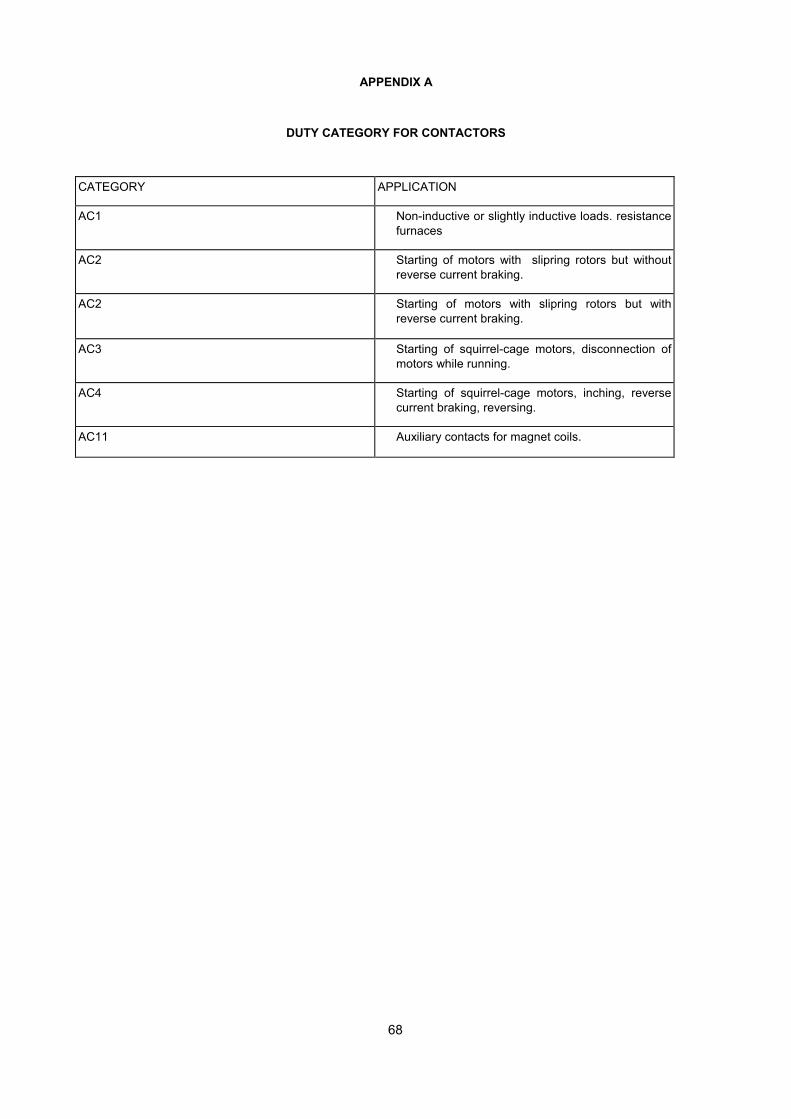
68
APPENDIX A
DUTY CATEGORY FOR CONTACTORS
CATEGORY APPLICATION
AC1 Non-inductive or slightly inductive loads. resistancefurnaces
AC2 Starting of motors with slipring rotors but withoutreverse current braking.
AC2 Starting of motors with slipring rotors but withreverse current braking.
AC3 Starting of squirrel-cage motors, disconnection ofmotors while running.
AC4 Starting of squirrel-cage motors, inching, reversecurrent braking, reversing.
AC11 Auxiliary contacts for magnet coils.
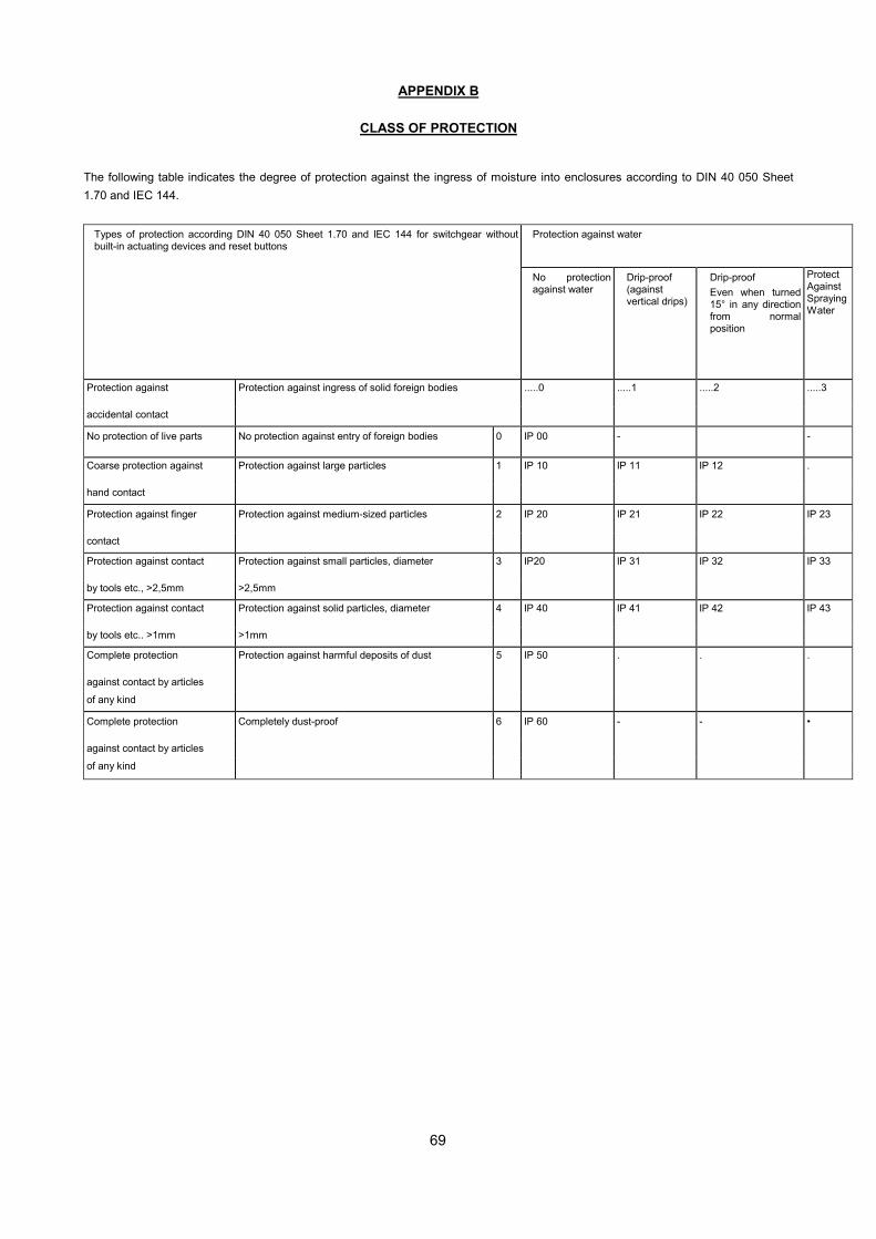
69
APPENDIX B
CLASS OF PROTECTION
The following table indicates the degree of protection against the ingress of moisture into enclosures according to DIN 40 050 Sheet1.70 and IEC 144.
Types of protection according DIN 40 050 Sheet 1.70 and IEC 144 for switchgear withoutbuilt-in actuating devices and reset buttons
Protection against water
No protectionagainst water
Drip-proof(againstvertical drips)
Drip-proofEven when turned15° in any directionfrom normalposition
ProtectAgainstSprayingWater
Protection against Protection against ingress of solid foreign bodies .....0 .....1 .....2 .....3
accidental contact
No protection of live parts No protection against entry of foreign bodies 0 IP 00 - -
Coarse protection against Protection against large particles 1 IP 10 IP 11 IP 12 .
hand contact
Protection against finger Protection against medium-sized particles 2 IP 20 IP 21 IP 22 IP 23
contact
Protection against contact Protection against small particles, diameter 3 IP20 IP 31 IP 32 IP 33
by tools etc., >2,5mm >2,5mm
Protection against contact Protection against solid particles, diameter 4 IP 40 IP 41 IP 42 IP 43
by tools etc.. >1mm >1mm
Complete protection Protection against harmful deposits of dust 5 IP 50 . . .
against contact by articles
of any kind
Complete protection Completely dust-proof 6 IP 60 - - •
against contact by articles
of any kind
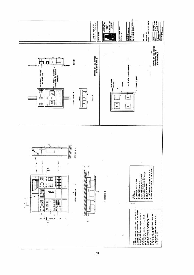
70
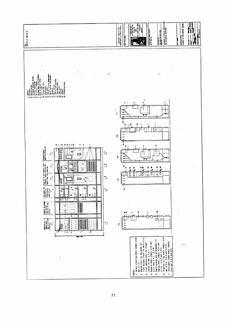
71

72

73

74
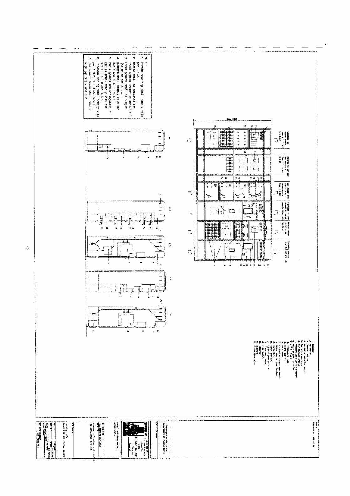
75