the electromagnetic spectrum a great many avionics systems use electromagnetic (em) waves to perform...
TRANSCRIPT

THE ELECTROMAGNETIC SPECTRUM
A great many avionics systems use electromagnetic (EM) waves to perform their functions
It is therefore useful to have a basic understanding of some of their characteristics

THE ELECTROMAGNETIC SPECTRUM
Important Characteristics of EM waves• As the name implies, an EM wave has an electric
(E) field component and a magnetic (H) field component
• These are always at 90 degrees to each other• The wave propagates at 90 degrees to both.
E
HDirectionOfPropagation

THE ELECTROMAGNETIC SPECTRUM
Important Characteristics of EM waves
• The speed of propagation, c, is approx 3 x 10⁸ m/s
• The wavelength λ is related to the frequency f by the equation λ=c/f
• The polarity is defined as the direction of the E field vector.

THE ELECTROMAGNETIC SPECTRUM
Typical Polarities are:
• Vertical• Horizontal• Circular
In circular polarization, the vectors rotate around the axis of propagation in a corkscrew fashion. They rotate together so that they are always 90º to each other
• Each polarity has characteristics which makes it useful for particular purposes

THE ELECTROMAGNETIC SPECTRUM
•Classification of the EM Spectrum
Band f λ
VLF (Very Low Frequency) 30kHz – 300kHz 10km – 1 km
LF (Low Frequency) 300kHz – 3MHz 1km – 100m
HF (High Frequency) 3MHz – 30MHz 100m – 10m
VHF (Very High Frequency) 30MHz – 300 MHz 10m – 1m
UHF (Ultra High Frequency) 300MHz – 3 GHz 1m – 10cm
SHF (Super High Frequency) 3Ghz – 30GHz 10 cm – 1 cm
THE ELECTROMAGNETIC SPECTRUM
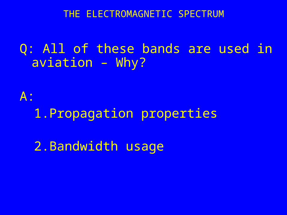
Q: All of these bands are used in aviation – Why?
A:1. Propagation properties
2. Bandwidth usage

THE ELECTROMAGNETIC SPECTRUM
Propagation – Ionosphere
The upper levels of the atmosphere are constantly ultraviolet radiation originating in the sun.
This radiation ionizes the atmospheric gases which results in several layers of electron plasma
For communication, the most important is the topmost or F layer which is situated at altitudes of 120km to 400km.

THE ELECTROMAGNETIC SPECTRUM
Propagation – Ionosphere
Within an ionospheric layer, the density of electrons varies from a minimum at the top and bottom, to a maximum in the middle.
Since the speed of an electromagnetic wave increases with electron density, the wave is refracted.

THE ELECTROMAGNETIC SPECTRUM
Propagation – Ionosphere
The amount of refraction is dependent on the frequency of the wave – higher frequency, less refraction.
If the frequency is low enough, the wave can be refracted back to earth

THE ELECTROMAGNETIC SPECTRUM
This phenomenon is used to transmit signals around the earth’s curvature

THE ELECTROMAGNETIC SPECTRUM
Problems:
•The height and electron density of any layer is highly variable, depending on the time of day, time of year, sunspot activity etc.•The ionosphere allows noise from thunderstorms in the equatorial region to be received at long distances thus increasing the noise level of communications.•Use of ionospheric reflection is limited to the HF band (3MHz to 30 MHz)

THE ELECTROMAGNETIC SPECTRUM
Bandwidth:
•The frequencies being discussed are what is called carrier frequencies.•A single frequency does not transmit any information•To transmit information, the carrier must be modified in some way.•This is called modulation

BANDWIDTH
One way to modify the carrier is to alter its amplitude with the information to be transmitted.
e.g.

BANDWIDTH
The spectrum of this signal is:
Thus, two extra signal are produced. One fm Hz above the carrier and one fm Hz below the carrier.
Thus the bandwidth, or amount of spectrum occupied, is 2 x fm
The main disadvantage of AM is susceptibility to interference
BANDWIDTH
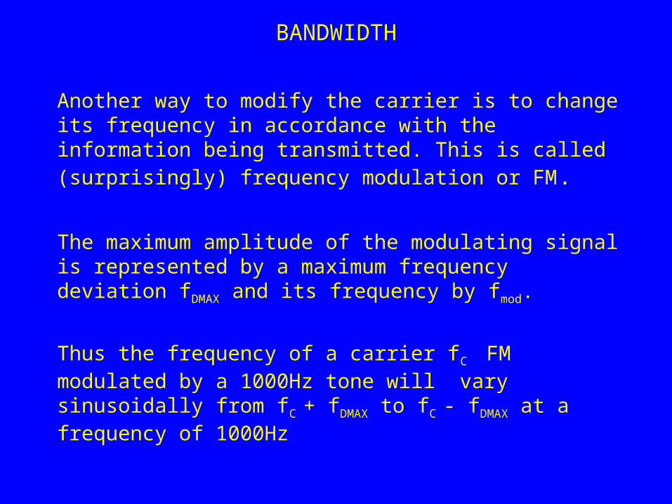
Another way to modify the carrier is to change its frequency in accordance with the information being transmitted. This is called (surprisingly) frequency modulation or FM.
The maximum amplitude of the modulating signal is represented by a maximum frequency deviation fDMAX and its frequency by fmod.
Thus the frequency of a carrier fC FM modulated by a 1000Hz tone will vary sinusoidally from fC + fDMAX to fC - fDMAX at a frequency of 1000Hz

BANDWIDTH
The quality of the signal is a function of the ratio fDMAX / fmod.
The bandwidth required is 2 x (fDMAX + fmod )
Reasonably good quality is achieved with fDMAX = fmod so the bandwidth required is 4 x fmod .
Thus it can be seen that the bandwidth required for a given modulation signal is roughly 2 – 4 times its frequency

BANDWIDTH
A third type of modulation varies the phase of the carrier and hence is called phase modulation (PM).
Since phase is the integral of frequency, its characteristics are similar to those of FM.
It is used primarily for digital data transmission

BANDWIDTH
The rate that information must be transmitted determines the modulating frequency
i.e. to transmit 1 Mbyte/s would require a modulating frequency of at least 1 MHz and thus would use about 4 MHz of bandwidth.

THE ELECTROMAGNETIC SPECTRUM
Spectrum Management
Because radio signals do not stop at national boundaries and signals occupying the same part of the spectrum will interfere with each other, the allotment of carrier frequencies and the type of modulation allowed on them, are controlled by international agreement through the ITU (International Telecommunications Union) which is part of the UN.
This group meets every two or three years to modify the spectrum allotments to accommodate changes in technology or requirements.

THE ELECTROMAGNETIC SPECTRUM
The Aeronautical Spectrum
Band Usage System Frequencies
VLF Navigation Omega (discontinued)
10kHz
LF Navigation LORAN C 1MHz
LF Navigation Non Directional Beacons
500-1600kHz
HF Communications Oceanic/Polar 3-30MHz
VHF Navigation ILS (Instrument Landing System)
108-112MHz
VHF Navigation VOR 108-118MHz
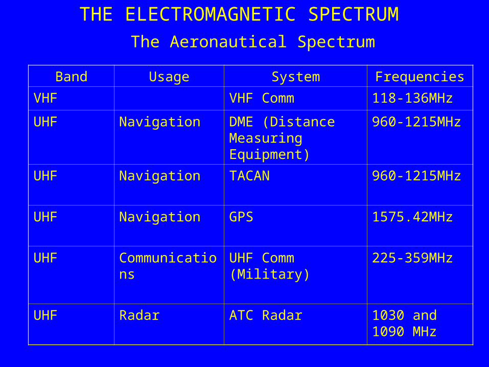
THE ELECTROMAGNETIC SPECTRUM
The Aeronautical Spectrum
Band Usage System Frequencies
VHF VHF Comm 118-136MHz
UHF Navigation DME (Distance Measuring Equipment)
960-1215MHz
UHF Navigation TACAN 960-1215MHz
UHF Navigation GPS 1575.42MHz
UHF Communications UHF Comm (Military) 225-359MHz
UHF Radar ATC Radar 1030 and 1090 MHz

THE ELECTROMAGNETIC SPECTRUM
The Aeronautical Spectrum
Band Usage System Frequencies
SHF Navigation MLS (Microwave Landing System
5.031-5.1907 GHz
SHF Communications Satellite Communications various
SHF Radar Airborne Weather Radar 10GHz
SHF Radar Radar Altimeter 4.2-4.4GHz
Above 30MHz
Radar Synthetic Vision 35GHz
Above 30MHz
Radar Passive infrared imaging

THE ELECTROMAGNETIC SPECTRUM
Antennas
Purpose:
Provides the link between the electromagnetic wave and either the receiver or transmitter

ANTENNAS
Definitions
Antenna Pattern
The antenna pattern describes the directional characteristics of an antenna.
i.e. the variation of sensitivity with direction for receiving antennas or the variation of power density with direction for transmitting antennas

ANTENNAS
Antenna Pattern
An antenna which radiates or is equally sensitive in all directions os called isotropic.
This is impossible to achieve in practice but it gives us a reference

ANTENNAS
Antenna Pattern
If an antenna is not isotropic, it is directional. i.e. it is more sensitive (or radiates more power) in some directions than in others.

ANTENNAS
Antenna Pattern
Directional antennas have what is called Gain which is the difference between the sensitivity (or power density) of the antenna compared to an isotropic antenna.

ANTENNAS
Polarity
• Not surprisingly, antennas exhibit polarity the same way that EM waves do.
• i.e. a vertically polarized waves are produced by a vertically polarized antenna
• The polarity of receiving antennas must match the polarity of the incoming wave to achieve maximum efficiency
• E.g. When a vertically polarized wave hits a horizontally polarized antenna, the antenna output is zero
ANTENNAS
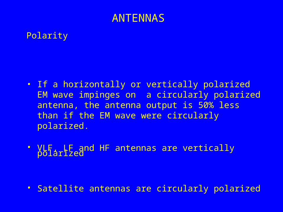
Polarity
• If a horizontally or vertically polarized EM wave impinges on a circularly polarized antenna, the antenna output is 50% less than if the EM wave were circularly polarized.
• VLF, LF and HF antennas are vertically polarized
• Satellite antennas are circularly polarized

ANTENNAS
Polarity
• VLF, LF and HF antennas are vertically polarized
– This is because, at these frequencies, the EM waves propagate as GROUND WAVES
– i.e.they use the fact that earth (and especially sea) are reasonably good conductors at low frequencies
– Also, the electric field must be perpendicular to any conducting surface

ANTENNAS
Polarity
• Satellite antennas are circularly polarized
– This is because the ionosphere rotates the polarity of the EM wave by a random amount (Faraday Effect)
– A linearly polarized wave would not likely match the polarity of the receiving antenna
– Circularly polarized signals simply experience a phase shift which does not affect the effectiveness of the receiving antenna

Types of Antennas
• Half-Wave Dipole– As the name implies, this antenna is made up of two
elements and is half a wavelength long
ANTENNAS
OUTPUT
λ/2
You could probably guess that this antenna is horizontally polarized
i.e. polarization is parallel to the axis of the antenna

Types of Antennas – Half Wave Dipole
ANTENNAS
VOR/ILS (Navigation) Antenna on CL601

Types of Antennas
• Quarter Wave Monopole– A conducting surface acts like a mirror for EM waves.
– This is used to make more compact antennas.
– E.g.
ANTENNAS
λ/4
OUTPUT

Quarter Wave Monopole– This example is vertically polarized
ANTENNAS
λ/4 Monopoles (VHF Communications)

Loop Antenna
– The λ/2 and λ/4 antennas respond to the Electric Field Component of the EM wave
– They are also tuned i.e. they respond to a narrow range of frequencies defined by their linear dimension.
– The Loop Antenna responds to the magnetic component of the EM wave
ANTENNAS

Loop AntennaANTENNAS
CURRENT
OUTPUT
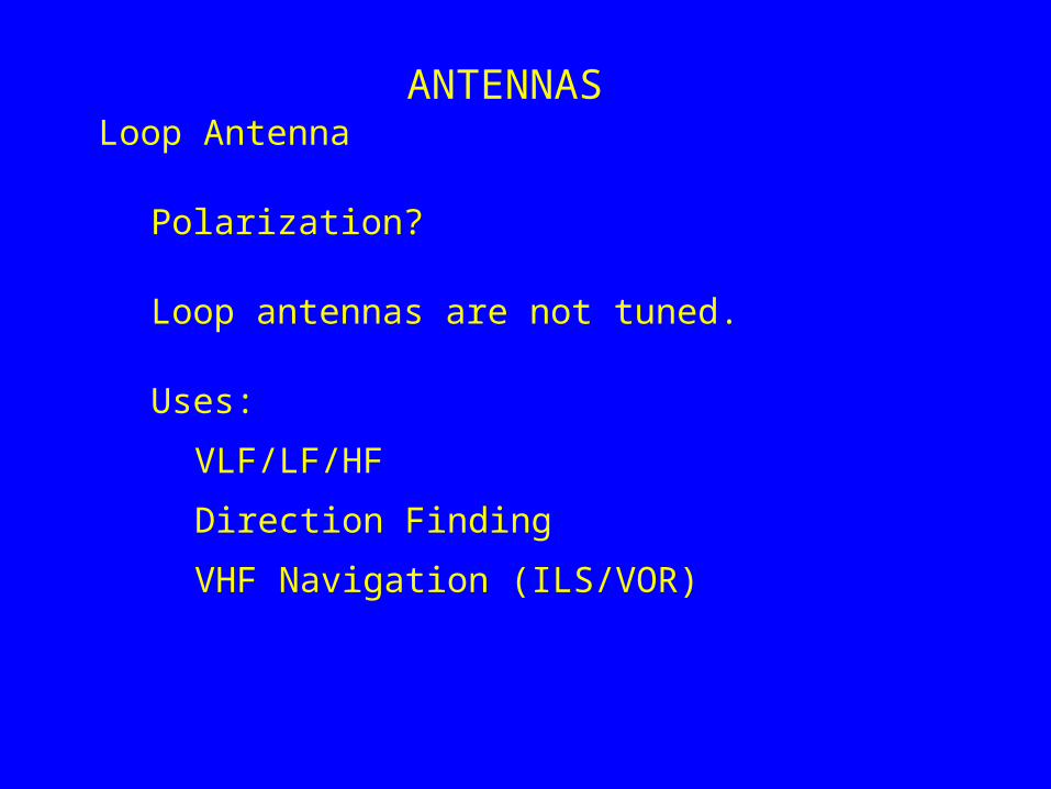
Loop Antenna
Polarization?
Loop antennas are not tuned.
Uses:
VLF/LF/HF
Direction Finding
VHF Navigation (ILS/VOR)
ANTENNAS

Long Wire AntennaANTENNAS
– Not practical for high speed aircraft
– Used for HF communications

Horn AntennaANTENNAS
– Used for microwave frequencies (1 GHz +)
– e.g. Weather radar
– Highly directional
– Usually used with a parabolic reflector

ANTENNASInstallation Considerations
– Antenna Patterns
• Usually as close to omnidirectional as possible– Or directional in the vertical plane only
– Usually downwards but for GPS, upwards
• The other and of the communications/navigation link is usually on the ground in an unknown direction.
• Exceptions– Weather radar
– Satellite communications (these need external pointing information)

ANTENNASInstallation Considerations
– Preferably Low Drag
– On bottom of aircraft, require protection from debris from runway
– Siting Considerations
• Shadowing from wings or other structures
• Sufficient separation from other antennas to avoid interference (severe problem on small aircraft)
• As close as possible to transmitter/receiver installation– Reduce cable losses
– Reduce number of connectors

ANTENNASInstallation Considerations
– Determining Location
• Analytical (mathematical) modelling– Fairly accurate for How Frequencies (aircraft structure
modelled as a series of conducting rods) and for
High Frequencies (aircraft modeled as a series of conducting plane surfaces)
– In between (VHF/UHF) this not very useful (wavelengths are close to size of aircraft structures

ANTENNASInstallation Considerations
– Determining Location
• Scale Modelling– Requires a large anechoic chamber
» A room lined with EM absorbing structures
– Scale model of aircraft used (usually about 1/10)
– Difficult to scale some properties (e.g. resistivity of skin should be 1/10 the resistivity of aluminum.

ANTENNASDetermining Location
ANECHOIC CHAMBER

ANTENNAS
Problems with Antennas
• Poor bonding between antenna and aircraft skin.
(especially for λ/4 monopoles)
• Cabling losses and faults
• Faulty or loose Connectors