the electromagnetic spectrum€¦ · electromagnetic radiation has, in addition to its wave nature,...
TRANSCRIPT

UNIVERSITY OF TECHNOLOGY LASER PRINCIPLE COURSE
DEP. OF LASER & OPTOELECTRONICS LEC.1
ENGINEERING
2ND YEAR
1
Definition: LASER is an acronym of:
Light Amplification by the Stimulated Emission of Radiation
The electromagnetic spectrum
Light, radio waves , x-rays , γ-rays are all E.M radiation,
The only difference between them is their frequency.
E.M radiation is propagated through space as a transverse wave; the speed of
propagation (c) is related to frequency by:
c =λ* f λ = wavelength One of the most important parameters of a wave is its wavelength.
Wavelength () (Lamda) is the distance between two adjacent points on the wave, which have the
same phase. As an example (see figure 1.1 below) the distance between two adjacent peaks of the
wave.
In a parallel way it is possible to define a wave by its frequency. Frequency () is defined by the
number of times that the wave oscillates per second (The number of periods of oscillations per
second).Between these two parameters the relation is: c =
From the physics point of view, all electromagnetic waves are equal (have the same properties)
except for their wavelength (or frequency).
As an example: the speed of light is the same for visible light, radio waves, or x-rays.
Wave Description: A wave can be described in two standard forms:
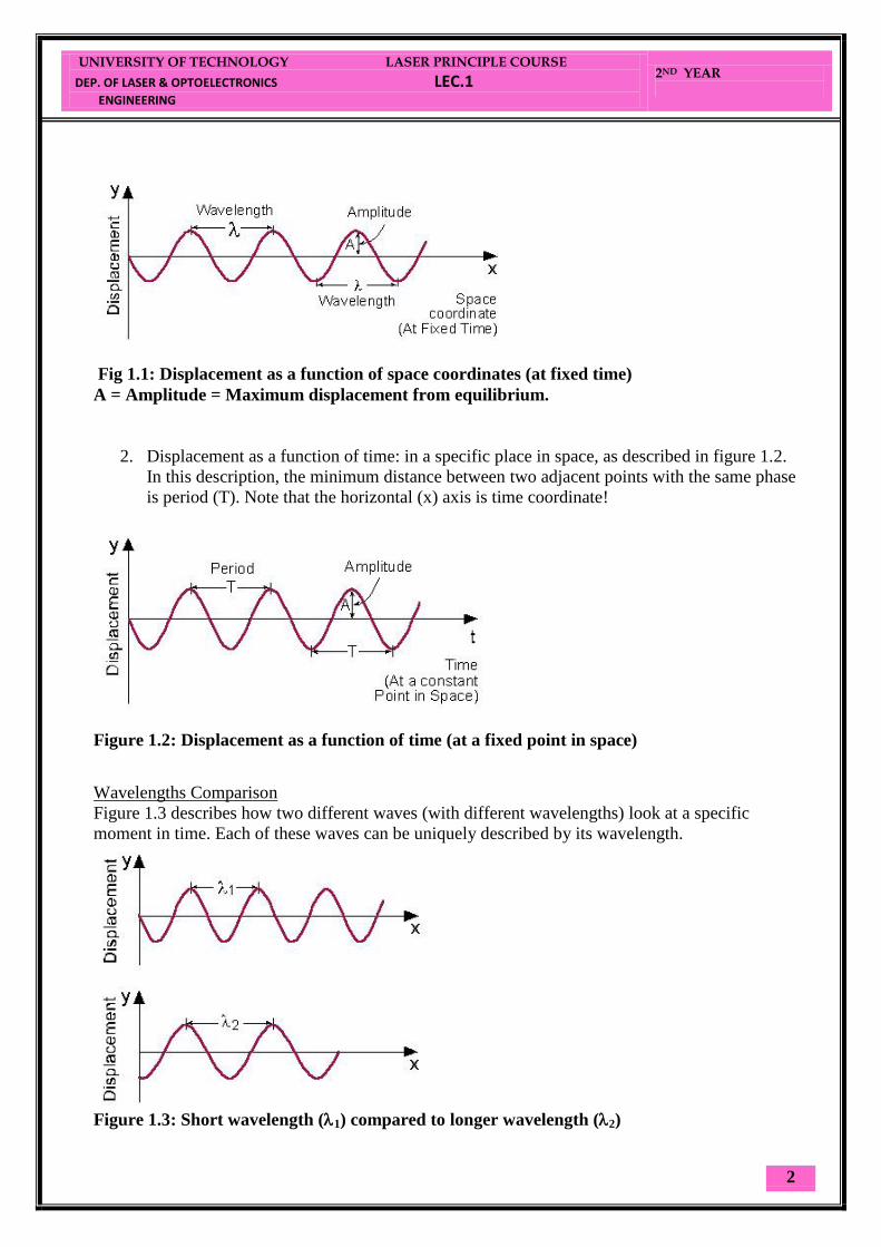
1. Displacement as a function of space when time is held constant.
2. Displacement as a function of time at a specific place in space.
1. Displacement as a function of space, when time is "frozen" (held constant), as described in
figure 1.1. In this description, the minimum distance between two adjacent points with the
same phase is wavelength (). Note that the horizontal (x) axis is space coordinate.
UNIVERSITY OF TECHNOLOGY LASER PRINCIPLE COURSE
DEP. OF LASER & OPTOELECTRONICS LEC.1
ENGINEERING
2ND YEAR
2
Fig 1.1: Displacement as a function of space coordinates (at fixed time)
A = Amplitude = Maximum displacement from equilibrium.
2. Displacement as a function of time: in a specific place in space, as described in figure 1.2.
In this description, the minimum distance between two adjacent points with the same phase
is period (T). Note that the horizontal (x) axis is time coordinate!
Figure 1.2: Displacement as a function of time (at a fixed point in space)
Wavelengths Comparison Figure 1.3 describes how two different waves (with different wavelengths) look at a specific
moment in time. Each of these waves can be uniquely described by its wavelength.
Figure 1.3: Short wavelength (1) compared to longer wavelength (2)

UNIVERSITY OF TECHNOLOGY LASER PRINCIPLE COURSE
DEP. OF LASER & OPTOELECTRONICS LEC.1
ENGINEERING
2ND YEAR
3
In vacuum the speed of light for any E.M radiation is equal to :
c= 3*108 m.s
-1
In a transparent medium the velocity (c') is less than (c).
This reduction is related to the refractive index of medium by:
Refractive index of the medium (n) = (velocity in vacuum / velocity in medium ) = c/c'
so : c'=c/n
As the radiation enters a region of higher ref. index, the wavelength is
reduced, the frequency remains constant.
Ref. index of air is ~ 1.0028 for visible light, the effect on λ due to air may be
ignored except for high accuracy work.

UNIVERSITY OF TECHNOLOGY LASER PRINCIPLE COURSE
DEP. OF LASER & OPTOELECTRONICS LEC.1
ENGINEERING
2ND YEAR
4
Photon energy Wavelength
(m)
Frequency
(HZ)
Region
100 kev
10 kev
1 kev
100 ev
10 ev
1 ev
0.1 ev
10-2
ev
10 -3
ev
10 -4
ev
10 -5
ev
10 -6
ev
10 -7
ev
.
.
10-10
ev
10-11
10-10
10-9
10-8
10-7
10-6
10-5
10-4
10-3
10-2
10-1
0
10
102
103
104
1020
1019
1018
1017
1016
1015
1014
1013
1012
1011
1010
109
108
107
106
105
γ-ray
x-ray
v.uv
u.v
visible I.R
F.I.R
microwave
radio freq
The E.M. spectrum
The energy of a quantum of light depends on its frequency.
E = h*f = h * υ
Where: h= planck's constant = 6.63*10-34
J.s
E in joules & f in Hz = s-1
E (joule) = hc/ λ = (6.63*10-34
*3*108)
/ λ (joules)
But: 1 ev = 1.6*10-19
J
So : E in (ev ) = (6.63*10-34
* 3*108) /( λ * 1.6 *10
-19) ev
=(1.243*10-6
)/ λ ev

UNIVERSITY OF TECHNOLOGY LASER PRINCIPLE COURSE
DEP. OF LASER & OPTOELECTRONICS LEC.2
ENGINEERING
2ND YEAR
1
Units
Velocity of light c = 3*108 ms
-1
Frequency = cycles per sec (cps) or Hz
Since frequency used lie in the range (1010
-- 1020
) Hz
Frequency usually expressed as wave number
wave number (cm-1
) = 1/ λ (cm) = f (Hz)/c(=3x1010
cm/s)
freq & wave number units have two advantages over wavelength units
1) They are both independent of the medium.
2) They are both directly proportional to the photon energy
Historical preview:
The idea of the amplification of the electro-magnetic radiation by the stimulated
emission was started after the 2nd
world war. The first use of stimulated emission
was in the building of the first MASER:
Multiplication factor name symbol
1012
109
106
103
10-2
10-3
10-6
10-9
10-12
10-15
10-18
Tera
Giga
Mega
Kilo
Centi
Milli
Micro
Nano
Pico
Femto
atto
T
G
M
K
c
m
μ
n
p
f
a
UNIVERSITY OF TECHNOLOGY LASER PRINCIPLE COURSE
DEP. OF LASER & OPTOELECTRONICS LEC.2
ENGINEERING
2ND YEAR
2
Microwave Amplification by the Stimulated Emission of Radiation) in 1954 by
TOWNES and his group in the USA (the system works in the radiation wavelength
of 1.25 cm which is used in RADAR), the active medium was the ammonia gas.
The population inversion was achieved by splitting the high energy molecules from
those in the lower level.
Later was the achievement of population inversion by pumping (optical
pumping) in 1955 then was the design of solid state masers (Ruby) in 1957.
There was a great hope to extend the application of the stimulated emission to
the visible part of the electro-magnetic spectrum (later called the Optical
maser).
Townes and Shawlow worked together in a study in 1958 to solve the problems
evolved from the manufacturing of optical maser, which may be;
1.The differences in energy levels to produce visible radiation are large
comparing to (KT) at room temperature, while for MASER those differences
are small. This means searching for different population schemes to
stimulate the energy level greater than that for MASER.
2.The spontaneous emission is greater than the stimulated emission (will be
discussed later), they also suggest interference system (Fabry –Perot
interferometer to work as a Resonator (two opposed mirrors and the active
medium is inserted between them).
The first optical maser was built by Theodore Maiman in 1960 in the USA,
using Ruby as an active medium producing 694.3 nm. This later called the
LASER.
After that, other solid lasers were discovered (using Uranium ions and rare
earth metal ions) such as Nd: YAG laser using flash lamps for pumping (before
the end of 1960).

UNIVERSITY OF TECHNOLOGY LASER PRINCIPLE COURSE
DEP. OF LASER & OPTOELECTRONICS LEC.2
ENGINEERING
2ND YEAR
3
Ali Javan at the end of 1960 operated the First gas laser ever, the He-Ne laser.
He successfully pumped it by electrical discharge producing 632.8nm
wavelength.
Semiconductor laser technology started in 1962 by exciting a semiconducting
material using electric field to produce optical emission at the junction region
(p-n). This construction is called the DIODE. Gallium Arsenide (GaAs) used
as the first semiconductor to produce a 810 nm laser, this technology depends
on:
a. Impurity concentration in the active medium
b. Temperature
c. The current passing through the diode.
Later on the discovery of liquid (Dye) laser and chemical lasers and many
other lasers was about 1963.

UNIVERSITY OF TECHNOLOGY LASER PRINCIPLE COURSE
DEP. OF LASER & OPTOELECTRONICS LEC.3
ENGINEERING
2ND YEAR
1
Lasing Process
To understand lasing processes, we have three parts:
1. Basic elements of the structure of matter - the atom.
2. Wave theory - especially electromagnetic waves.
3. The interaction of electromagnetic radiation with matter.
2.1 Bohr model of the atom. Lasing action is a process that occurs in matter. Since matter is composed of atoms, we need to
understand (a little) about the structure of the atom, and its energy states. We shall start with Bohr
model of the atom.
According to this model, every atom is composed of a very massive nucleus with a positive
electric charge (Ze); around it electrons are moving in specific paths.
Z = Number of protons in the nucleus,
e = Elementary charge of the electrons:
e = 1.6*10-19
Coulomb
Figure 2.1 illustrates a simple, but adequate, picture of the atom, the Bohr model:
Fig 2-1: Bohr picture of the Atom
Every "orbit" of the electron around the nucleus, is connected to a specific energy level. The
energy level is higher as the distance of the "orbit" from the nucleus increases.
UNIVERSITY OF TECHNOLOGY LASER PRINCIPLE COURSE
DEP. OF LASER & OPTOELECTRONICS LEC.3
ENGINEERING
2ND YEAR
2
Since for each atom there are only certain "allowed orbits", only certain discrete energy levels
exist, and are named: E1, E2, E3, etc.
Energy States (Levels) Every atom or molecule in nature has a specific structure for its energy levels.
The lowest energy level is called the ground state,
which is the naturally preferred energy state. As long as no energy is added to the atom, the
electron will remain in the ground state.
When the atom receives energy (electrical energy, optical energy, or any form of energy), this
energy is transferred to the electron, and raises it to a higher energy level (in our model further
away from the nucleus).The atom is then considered to be in an excited state.
The electron can "jump" from one energy level to another, while receiving or emitting specific
amounts of energy.
These specific amounts of energy are equal to the difference between energy levels within
the atom.
Energy transfer to and from the atom Energy transfer to and from the atom can be performed in two different ways:
1. Collisions with other atoms, and the transfer of kinetic energy as a result of the
collision. This kinetic energy is transferred into internal energy of the atom.
2. Absorption and emission of electromagnetic radiation.
Since we are now interested in the lasing process, we shall concentrate on the second
mechanism of energy transfer to and from the atom (The first excitation mechanism is used in
certain lasers, like Helium-Neon, as a way to put energy into the laser.
2.2 Photons and the energy diagrams
Electromagnetic radiation has, in addition to its wave nature, some aspects of "particle like
behavior". These are called "Photons".
The relation between the amount of energy (E) carried by the photon and its frequency (), is
determined by the formula (first given by Einstein):
E = h
The proportionality constant in this formula is Planck's constant (h):
h = 6.626*10-34
Joule-sec
This formula can be expressed in different form, by using the relation between the frequency ()
and the wavelength: c = to get:
E = h * c/.
UNIVERSITY OF TECHNOLOGY LASER PRINCIPLE COURSE
DEP. OF LASER & OPTOELECTRONICS LEC.3
ENGINEERING
2ND YEAR
3
This formula shows that the energy of each photon is inversely proportional to its wavelength.
This means that each photon of shorter wavelength (such as violet light) carries more energy than
a photon of longer wavelength (such as red light).
When this energy is absorbed or emitted in a form of electromagnetic radiation, the energy
difference between these two energy levels (E2-E1) determines uniquely the frequency () of the
electromagnetic radiation: (E) = E2-E1 = h
Example 2.1: Visible Spectrum
The visible spectrum wavelength range is: 0.4 - 0.7 m (400-700 nm).
The wavelength of the violet light is the shortest, and the wavelength of the red light is the longest.
Calculate:
a) What is the frequency range of the visible spectrum?
b) What is the amount of the photon’s energy associated with the violet light, compared to
the photon energy of the red light?
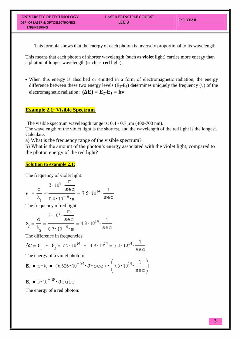
Solution to example 2.1:
The frequency of violet light:
The frequency of red light:
The difference in frequencies:
The energy of a violet photon:
The energy of a red photon:
UNIVERSITY OF TECHNOLOGY LASER PRINCIPLE COURSE
DEP. OF LASER & OPTOELECTRONICS LEC.3
ENGINEERING
2ND YEAR
4
The difference in energies between the violet photon and the red photon is: 2.15*10
-19 J.
This example shows how much more energy the violet photon have compared to the red
photon.

UNIVERSITY OF TECHNOLOGY LASER PRNICIPLE COURSE
DEP. OF LASER & OPTOELECTRONICS LEC.4
ENGINEERING
2ND YEAR
1
Question 2.1: Is it allowed to calculate first the wavelength difference (2-1), and then use the relation
between frequency and wavelength (2-1)= c/(2-1) ?
Question 2.2:
Calculate in units of Nanometer, the wavelength of light emitted by the transition from energy
level E3 to energy level E2 in a 3 level system in which:
E1 = 0 eV
E2 = 1.1 eV
E3 = 3.5 eV
2.3 Absorption of electromagnetic Radiation We saw that the process of photon absorption by the atom is a process of raising the atom
(electron) from a lower energy level into a higher energy level (excited state), by an amount of
energy which is equivalent to the energy of the absorbed photon.
When electromagnetic radiation passes through matter, part of it is transmitted, and part is
absorbed by the atoms.
The intensity (I) of the transmitted radiation through a thickness (x) of homogeneous material is
described by the experimental equation of exponential absorption (Lambert Law):
I=I0 exp (-x)
I0 = Intensity of incoming radiation.
= Absorption coefficient of the material.
The thicker the material (bigger x), the lower the intensity after the material (the transmitted
beam).
It is common to use units of centimeter (10-2
m), to measure the width of the material (x), so the
units of the absorption coefficient () are:
cm-1
= 1/cm.
Example 2.2: Absorption Coefficient ()
Calculate the absorption coefficient () of materials which transmit 50% of the intensity of the
incident radiation on a 10 mm width, to the other side. Solution to example 2.2:
Using the exponential absorption law:
= -1/x * ln (I/I0) = - 1/1 * ln (0.5/1) = 0.69 cm-1

UNIVERSITY OF TECHNOLOGY LASER PRNICIPLE COURSE
DEP. OF LASER & OPTOELECTRONICS LEC.4
ENGINEERING
2ND YEAR
2
2.4 Spontaneous emission of electromagnetic Radiation One of the basic physical principles (which is the basis of a subject in physics called
Thermodynamics) is that:
Every system in nature "prefers" to be in the lowest energy state.
This state is called the Ground state. As an example, we mentioned this principle in the Bohr
model of the atom. When energy is applied to a system, the atoms in the material are excited, and
raised to a higher energy level. (The terms "excited atoms", "excited states", and "excited
electrons" are used here with no distinction).
These electrons will remain in the excited state for a certain period of time, and then will return
to lower energy states while emitting energy in the exact amount of the difference between the
energy levels (delta E).
If this package of energy is transmitted as electromagnetic energy, it is called photon. The
emission of the individual photon is random, being done individually by each excited atom, with
no relation to photons emitted by other atoms. When photons are randomly emitted from different
atoms at different times, the process is called Spontaneous Emission.
2.5 Boltzmann Distribution Equation From thermodynamics we know that a collection of atoms, at a temperature T [
0K], in
thermodynamic equilibrium with its surrounding, is distributed according to Boltzmann equation
which determines the relation between the population number of a specific energy level and the
temperature:
Ni= Constant * exp (-Ei/kT) Ni = Population Number = number of atoms per unit volume at certain energy level Ei.
k = Boltzmann constant: k = 1.38*1023
[Joule/0K].
Ei = Energy of level i. We assume that Ei> Ei-1 (ex: E2 > E1).
Const = proportionality constant.
It is not important when we consider population of one level compared to the population of
another level as we shall see shortly. T=Temperature in degrees Kelvin [0K] (Absolute
Temperature).
The Boltzmann equation shows the dependence of the population number (Ni) on the energy level
(Ei) at a temperature T. From this equation we see that:
1. The higher the temperature, the higher the population number.
2. The higher the energy level, the lower the population number.
UNIVERSITY OF TECHNOLOGY LASER PRNICIPLE COURSE
DEP. OF LASER & OPTOELECTRONICS LEC.4
ENGINEERING
2ND YEAR
3
Relative Population (N2/N1): The relative population (N2/N1) of two energy levels E2 compared to E1 is:
N2/N1 = const* exp (-E2/kT)/ const* exp (-E1/kT)
N2/N1 = exp (-(E2-E1)/kT).
The proportionality constant (const) is canceled by division of the two population numbers.
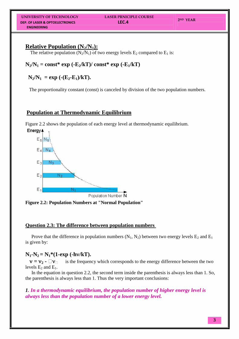
Population at Thermodynamic Equilibrium
Figure 2.2 shows the population of each energy level at thermodynamic equilibrium.
Figure 2.2: Population Numbers at "Normal Population"
Question 2.3: The difference between population numbers
Prove that the difference in population numbers (N1, N2) between two energy levels E2 and E1
is given by:
N1-N2 = N1*(1-exp (-h/kT).
= 2 - is the frequency which corresponds to the energy difference between the two
levels E2 and E1.
In the equation in question 2.2, the second term inside the parenthesis is always less than 1. So,
the parenthesis is always less than 1. Thus the very important conclusions:
1. In a thermodynamic equilibrium, the population number of higher energy level is
always less than the population number of a lower energy level.
UNIVERSITY OF TECHNOLOGY LASER PRNICIPLE COURSE
DEP. OF LASER & OPTOELECTRONICS LEC.4
ENGINEERING
2ND YEAR
4
2. The lower the energy difference between the energy levels, the less is the difference
between the population numbers of these two levels.
Physically, the electrons inside the atom prefer to be at the lowest energy level possible.
UNIVERSITY OF TECHNOLOGY LASER PRINCIPLE COURSE
DEP. OF LASER & OPTOELECTRONICS LEC.5
ENGINEERING
2ND YEAR
1
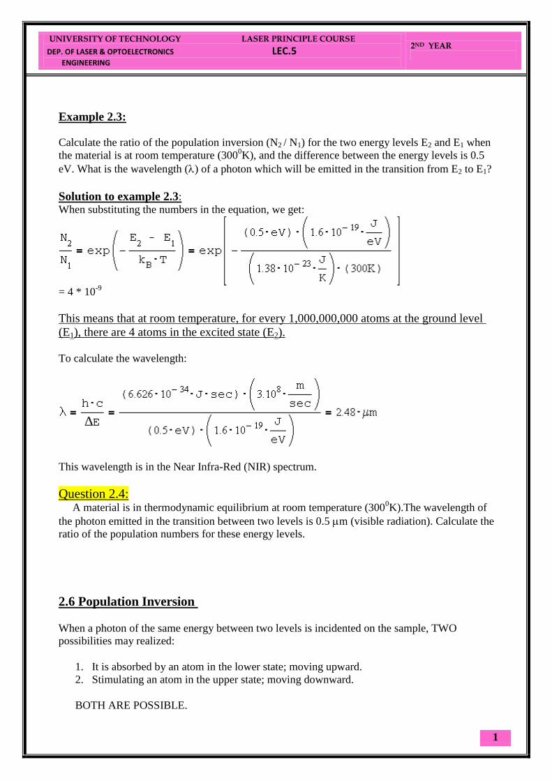
Example 2.3:
Calculate the ratio of the population inversion (N2 / N1) for the two energy levels E2 and E1 when
the material is at room temperature (3000K), and the difference between the energy levels is 0.5
eV. What is the wavelength () of a photon which will be emitted in the transition from E2 to E1?
Solution to example 2.3:
When substituting the numbers in the equation, we get:
= 4 * 10
-9
This means that at room temperature, for every 1,000,000,000 atoms at the ground level
(E1), there are 4 atoms in the excited state (E2).
To calculate the wavelength:
This wavelength is in the Near Infra-Red (NIR) spectrum.
Question 2.4: A material is in thermodynamic equilibrium at room temperature (300
0K).The wavelength of
the photon emitted in the transition between two levels is 0.5 m (visible radiation). Calculate the
ratio of the population numbers for these energy levels.
2.6 Population Inversion
When a photon of the same energy between two levels is incidented on the sample, TWO
possibilities may realized:
1. It is absorbed by an atom in the lower state; moving upward.
2. Stimulating an atom in the upper state; moving downward.
BOTH ARE POSSIBLE.

UNIVERSITY OF TECHNOLOGY LASER PRINCIPLE COURSE
DEP. OF LASER & OPTOELECTRONICS LEC.5
ENGINEERING
2ND YEAR
2
If N2 > N1 2nd
possibility (stimulated emission).
If N1 > N2 Absorption
But We saw that in a thermodynamic equilibrium Boltzmann equation shows us that:
N1 > N2 > N3
Thus, the population numbers of higher energy levels are smaller than the population numbers
of lower ones. This situation is called "Normal Population" (as described in Figure 2.3a).
By putting energy into a system of atoms, we can achieve a situation of
"Population Inversion".
In population inversion, at least one of the higher energy levels has more
atoms than a lower energy level.
An example is described in Figure 2.3b. In this situation there are more atoms (N3) in a higher
energy level (E3), than the number of atoms (N2) in a lower energy level (E2).
Figure 2.3: "Normal Population" compared to "Population Inversion".

UNIVERSITY OF TECHNOLOGY LASER PRINCIPLE COURSE
DEP. OF LASER & OPTOELECTRONICS LEC.5
ENGINEERING
2ND YEAR
3
This is one of the necessary conditions for lasing.
The process of raising the number of excited atoms is called "Pumping".
If this process is done by optical excitation (electromagnetic beam), it is called
"Optical Pumping".
2.7 Stimulated Emission Atoms stay in an excited level only for a short time (about 10
-8 [sec]), and then they return to a
lower energy level by spontaneous emission.
If a population inversion exists between two energy levels, the probability is high that an
incoming photon will stimulate an excited atom to return to a lower state, while emitting another
photon of light.
Possible Processes between Photons and Atoms
Figure 2.4 summarizes the three possible processes between photons and atoms: absorption,
spontaneous emission, and stimulated emission.
Photon Absorption: A photon with frequency 12 hits an atom at rest (left), and excites it to
higher energy level (E2) while the photon is absorbed.
Spontaneous emission of a photon: An atom in an excited state (left) emits a photon with
frequency 12 and goes to a lower energy level (E1).
Stimulated emission of a photon: A photon with frequency 12 hit an excited atom (left), and cause
emission of two photons with frequency 12 while the atom goes to a lower energy level (E1).

UNIVERSITY OF TECHNOLOGY LASER PRINCIPLE COURSE
DEP. OF LASER & OPTOELECTRONICS LEC.5
ENGINEERING
2ND YEAR
4
Now, E2 –E1 = hυ21 >>> kT,
Hence the ratio of N2 / N1 is very small, i.e only few atoms are in the upper level.
So:
To measure kT at room temperature (T=300 K),
so at kT=hυ,
Hence υ = 6x10¹²
Hz
So λ = 50 μm this is I.R
But for transition frequency in the visible and N.I.R (optical region):
So: N2 <<<N1
Example:
For a ruby crystal the energy gap (energy difference between transition levels) is
corresponding to λ = 0.69 μm, (or υ=c/ λ =3x10⁸/0.69x10
-6 )
So: E2 –E1 =h υ =6.63x 10-34
x 3x108/0.69x10
-6 =2.88 x 10
-19 Joule
KT= 1.38x10⁻²³
J/k x 300 = 4.14x10⁻²¹
So: N2/N1= exp (-ΔE/kT)
= ~ 10-31
i.e For each 1 atom in the upper state there is 1031
atoms in the ground state !!!
Almost all atoms are in the ground state at thermal equilibrium.
So to get laser action in the sample we need a POPULATION INVERSION

UNIVERSITY OF TECHNOLOGY LASER PRINCIPLE COURSE
DEP. OF LASER & OPTOELECTRONICS LEC.5
ENGINEERING
2ND YEAR
5

UNIVERSITY OF TECHNOLOGY LASER PRINCIPLE COURSE
DEP. OF LASER & OPTOELECTRONICS LEC.6
ENGINEERING
2ND YEAR
1
Einstein Coefficients
In a two – level system, the no. of atoms in the two-level system is constant, hence:
Ntotal = N1 + N2
Where : N1 and N2 are the no. of atoms in each of the two levels.
It is either of the processes:
Absorption from E1 to E2
OR:
Emission from E2 to E1.
As we mentioned before, there are three types of interactions between the atomic system &
the electromagnetic radiation:
1. Absorption
The rate of depletion from ground (E1) is proportional to the radiative density ρ(υ ) and
N1.
So:
dN1/dt = - B12 ρ(υ ) N1 ……………..(1)
B12 = Proportionality constant (Einstein coefficient)
B12 ρ(υ ) = Probability per unit frequency that transition occur due to the field effect.
2. Spontaneous emission
After absorption, the population of the upper level will be decayed spontaneously in a
rate proportional to the upper level.
dN2/dt = - A21 N2 ……………..(2) A21 = probability of spontaneous emission.
The solution of the differential equation (2) is :
N2(t) = N 2(0) exp (-t/τ21)
Where:
1/A21 = lifetime = τ21
Lifetime = 1/transition probability
UNIVERSITY OF TECHNOLOGY LASER PRINCIPLE COURSE
DEP. OF LASER & OPTOELECTRONICS LEC.6
ENGINEERING
2ND YEAR
2
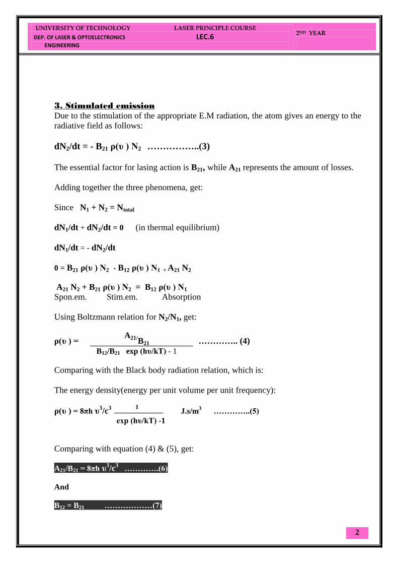
3. Stimulated emission
Due to the stimulation of the appropriate E.M radiation, the atom gives an energy to the
radiative field as follows:
dN2/dt = - B21 ρ(υ ) N2 ……………..(3)
The essential factor for lasing action is B21, while A21 represents the amount of losses.
Adding together the three phenomena, get:
Since N1 + N2 = Ntotal
dN1/dt + dN2/dt = 0 (in thermal equilibrium)
dN1/dt = - dN2/dt
0 = B21 ρ(υ ) N2 - B12 ρ(υ ) N1 + A21 N2
A21 N2 + B21 ρ(υ ) N2 = B12 ρ(υ ) N1
Spon.em. Stim.em. Absorption
Using Boltzmann relation for N2/N1, get:
ρ(υ ) = A21/
B21 ………….. (4)
B12/B21 exp )hυ/kT) - 1
Comparing with the Black body radiation relation, which is:
The energy density(energy per unit volume per unit frequency):
ρ(υ ) = 8πh υ3/c
3
1 J.s/m
3 …………..(5)
exp (hυ/kT) -1
Comparing with equation (4) & (5), get:
A21/B21 = 8πh υ3/c
3 ………….(6)
And
B12 = B21 ………………(7)

UNIVERSITY OF TECHNOLOGY LASER PRINCIPLE COURSE
DEP. OF LASER & OPTOELECTRONICS LEC.6
ENGINEERING
2ND YEAR
3
Conclusion:
From eq(7), Einstein coeff. For stimulating emission and absorption are EQUAL
i.e Probability of absorption is equivalent to probability of stimulated emission.
Now consider (R) ,as the ratio of spontaneous to stimulated emission probabilities,
hence for a two level system of energy levels, we have:
R = A21 N2 / B21 ρ(υ ) N2
Substituting for A21/B21 from eq(6) , and ρ(υ ) from eq(5), get:
R = exp )hυ/kT) – 1 ………..(8)
Example.1: For a tungsten lamp that works at temp. ~ 2000k and emission frequency 5x10
14 Hz,
Find R.
R ~ 1.5x10⁵
At room temperature R ~ 4x1034
Hence spontaneous emission is PREDOMINENT.
Example.2 Find R at 50μm and 2000k
R = 0.15
If λ = 60 μm & room temperature:
R = 1
Hence all examples are for systems in thermal equilibrium, stimulated emission
needs population inversion (i.e To destroy the thermal equilibrium).
UNIVERSITY OF TECHNOLOGY LASER PRINCIPLE COURSE
DEP. OF LASER & OPTOELECTRONICS LEC.7
ENGINEERING
2ND YEAR
1
The Optical Resonator In most cases the gain of a pumped medium is very small (0.1m-1), so the
amplification of the optical beam passing once is minimal, but the
amplification is increased by placing highly reflecting mirrors at each
end of the medium, this is forming the RESONATOR
Resonator + A.M = Oscillator
The gain within the medium must be large enough to overcome the
losses in the laser system.
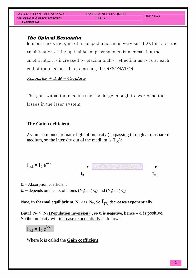
The Gain coefficient
Assume a monochromatic light of intensity (I0),passing through a transparent
medium, so the intensity out of the medium is (I(x)):
I(x) = I0 e-α x
α = Absorption coefficient
α – depends on the no. of atoms (N1) in (E1) and (N2) in (E2)
Now, in thermal equilibrium, N1 >>> N2, So I(x) decreases exponentially.
But if N2 > N1 (Population inversion) , so α is negative, hence – α is positive,
So the intensity will increase exponentially as follows:
I(x) = I0 ekx
Where k is called the Gain coefficient.
I0 I(x)
UNIVERSITY OF TECHNOLOGY LASER PRINCIPLE COURSE
DEP. OF LASER & OPTOELECTRONICS LEC.7
ENGINEERING
2ND YEAR
2
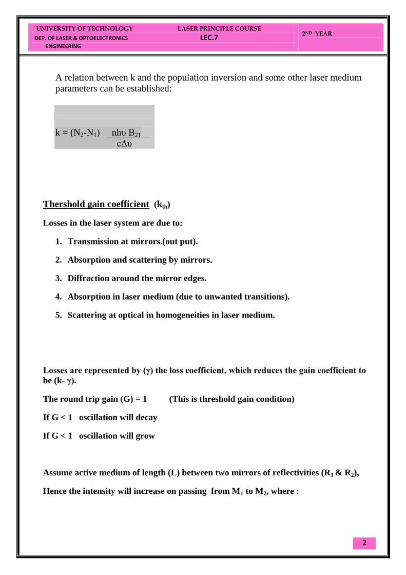
A relation between k and the population inversion and some other laser medium
parameters can be established:
k = (N2-N1) nhυ B21
cΔυ
Thershold gain coefficient (kth)
Losses in the laser system are due to:
1. Transmission at mirrors.(out put).
2. Absorption and scattering by mirrors.
3. Diffraction around the mirror edges.
4. Absorption in laser medium (due to unwanted transitions).
5. Scattering at optical in homogeneities in laser medium.
Losses are represented by (γ) the loss coefficient, which reduces the gain coefficient to
be (k- γ).
The round trip gain (G) = 1 (This is threshold gain condition)
If G < 1 oscillation will decay
If G < 1 oscillation will grow
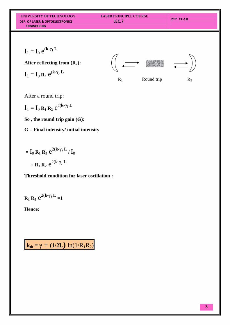
Assume active medium of length (L) between two mirrors of reflectivities (R1 & R2),
Hence the intensity will increase on passing from M1 to M2, where :
UNIVERSITY OF TECHNOLOGY LASER PRINCIPLE COURSE
DEP. OF LASER & OPTOELECTRONICS LEC.7
ENGINEERING
2ND YEAR
3
I1 = I0 e(k-γ)
L
After reflecting from (R2):
I1 = I0 R2 e(k-γ)
L
After a round trip:
I1 = I0 R1 R2 e2(k-γ)
L
So , the round trip gain (G):
G = Final intensity/ initial intensity
= I0 R1 R2 e2(k-γ)
L
/ I0
= R1 R2 e2(k-γ)
L
Threshold condition for laser oscillation :
R1 R2 e2(k-γ)
L
=1
Hence:
kth = γ + (1/2L) ln(1/R1R2)
Round trip R1 R2

UNIVERSITY OF TECHNOLOGY LASER PRINCIPLE COURSE
DEP. OF LASER & OPTOELECTRONICS LEC.8
ENGINEERING
2ND YEAR
1
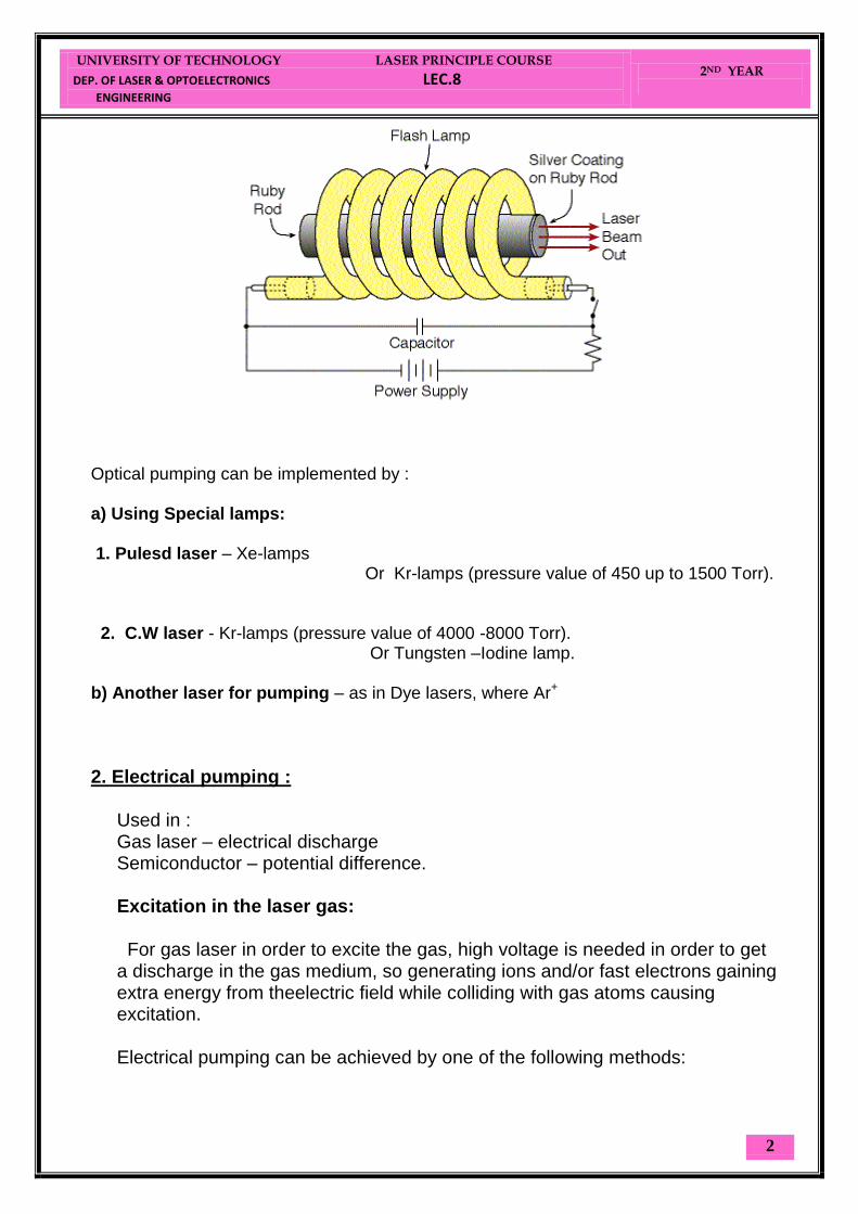
Basic components of a Laser system
1. Pumping : (To produce population inversion).
2. The Active medium : 3. The Resonator : (For optical feedback).
Pumping process: Types of pumping:
1. Optical pumping: High power light source to excite the active medium,
where the A.M absorbes the energy that helps atoms, molecules or ions to move to the upper level, this is common in solid state lasers (Ruby, Nd:YAG,…….etc.) or Dye lasers.
UNIVERSITY OF TECHNOLOGY LASER PRINCIPLE COURSE
DEP. OF LASER & OPTOELECTRONICS LEC.8
ENGINEERING
2ND YEAR
2
Optical pumping can be implemented by : a) Using Special lamps: 1. Pulesd laser – Xe-lamps Or Kr-lamps (pressure value of 450 up to 1500 Torr). 2. C.W laser - Kr-lamps (pressure value of 4000 -8000 Torr). Or Tungsten –Iodine lamp. b) Another laser for pumping – as in Dye lasers, where Ar+
2. Electrical pumping :
Used in : Gas laser – electrical discharge Semiconductor – potential difference. Excitation in the laser gas: For gas laser in order to excite the gas, high voltage is needed in order to get a discharge in the gas medium, so generating ions and/or fast electrons gaining extra energy from theelectric field while colliding with gas atoms causing excitation. Electrical pumping can be achieved by one of the following methods:

UNIVERSITY OF TECHNOLOGY LASER PRINCIPLE COURSE
DEP. OF LASER & OPTOELECTRONICS LEC.8
ENGINEERING
2ND YEAR
3
A) e (fast) +X (atom in the ground state) = X*(atom in the excited state) +e (Slow)
B) A gas comprising of TWO species (A & B)
A* + B = A + B
* (ΔE)
3. Chemical pumping
Does not need external source of energy, where the out put of the chemical reaction represents the active medium and the reaction generated energy can be used to excite the active medium and getting the population inversion. Ex: Hydrogen fluoride laser F + H2 HF* + H H +F2 HF* + F
Active Medium
+ -
A
A B B
+ ΔE
Before collision After collision
UNIVERSITY OF TECHNOLOGY LASER PRINCIPLE COURSE
DEP. OF LASER & OPTOELECTRONICS LEC.8
ENGINEERING
2ND YEAR
4
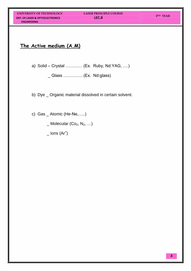
The Active medium (A.M)
a) Solid – Crystal ………… (Ex. Ruby, Nd:YAG, ….)
_ Glass ………….. (Ex. Nd:glass)
b) Dye _ Organic material dissolved in certain solvent.
c) Gas _ Atomic (He-Ne,…..)
_ Molecular (Co2, N2, …) _ Ions (Ar+)

UNIVERSITY OF TECHNOLOGY LASER PRINCIPLE COURSE
DEP. OF LASER & OPTOELECTRONICS LEC.9
ENGINEERING
2ND YEAR
1
Optical Resonators Formed usually by placing mirrors (plane or curved) to the axis along laser light
propagation.
Resonator Configurations.
(i) Plane-Parallel resonator (Fabry-Perot):
- Two plane mirrors set parallel to one another.
- As approximation, the modes of this resonator can be thought as a superposition of
two plane e.m works propagating in opposite directions along the cavity axis.
- Within this approximation, the resonant frequencies can be reading obtained by
imposing the condition that the cavity length (L) must be an integral number of
, i.e
- This is a necessary condition for the electric field of an e.m standing wave to be
zero on the two mirrors.
L
Figure (1): Resonator.
UNIVERSITY OF TECHNOLOGY LASER PRINCIPLE COURSE
DEP. OF LASER & OPTOELECTRONICS LEC.9
ENGINEERING
2ND YEAR
2
υ The resonant frequency:
Advantages:
Optimal use of all the volume of the active medium. Thus, used in pulsed lasers which need the maximum energy.
No focusing of the laser radiation inside the optical cavity. In high power lasers such
Disadvantages:
High diffraction losses. Very high sensitivity to misalignment. Thus, very difficult to operate.
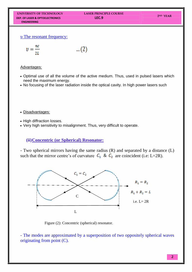
(ii) Concentric (or Spherical) Resonator:
- Two spherical mirrors having the same radius (R) and separated by a distance (L)
such that the mirror centre’s of curvature are coincident (i.e: L=2R).
- The modes are approximated by a superposition of two oppositely spherical waves
originating from point (C).
i.e. L= 2R
Figure (2): Concentric (spherical) resonator.
C
L

UNIVERSITY OF TECHNOLOGY LASER PRINCIPLE COURSE
DEP. OF LASER & OPTOELECTRONICS LEC.9
ENGINEERING
2ND YEAR
3
Advantages:
Very low sensitivity to misalignment. Thus, very easy to align. Low diffraction losses.
Disadvantages:
Limited use of the volume of the active medium. Used in optical pumping of continuous Dye lasers. In these lasers the liquid dye is flowing in the region of the beam focusing (The flow direction is perpendicular to the optical axis of the laser). Thus very high power density is used to pump the dye.
Maximum focusing of the laser radiation inside the optical cavity. Such focusing can cause electric breakdown, or damage to the optical elements.
(iii) Confocal Resonator
- Two spherical mirrors of the same (R) and separated by (L) such that the foci &
are coincident.
- C of one mirror lies on the surface of the second mirror (L=R).
2
Figure (3): Confocal resonator.
L
1
UNIVERSITY OF TECHNOLOGY LASER PRINCIPLE COURSE
DEP. OF LASER & OPTOELECTRONICS LEC.10
ENGINEERING
2ND YEAR
1
Advantages:
Little sensitivity to misalignment. Thus, easy to align. Low diffraction losses. No high focusing inside the cavity.
The main difference between the Confocal cavity and the spherical cavity is that in the Confocal cavity the focal point of each mirror is at the center of the cavity, while in spherical cavity the center of curvature of the mirrors is in the center of the cavity.
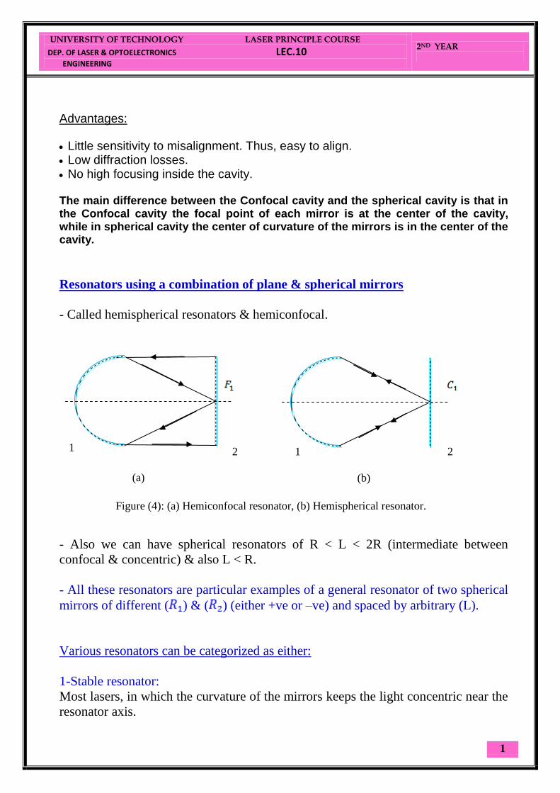
Resonators using a combination of plane & spherical mirrors
- Called hemispherical resonators & hemiconfocal.
- Also we can have spherical resonators of R < L < 2R (intermediate between
confocal & concentric) & also L < R.
- All these resonators are particular examples of a general resonator of two spherical
mirrors of different ( ) & ( ) (either +ve or –ve) and spaced by arbitrary (L).
Various resonators can be categorized as either:
1-Stable resonator:
Most lasers, in which the curvature of the mirrors keeps the light concentric near the
resonator axis.
2
(a)
1 1 2
(b)
Figure (4): (a) Hemiconfocal resonator, (b) Hemispherical resonator.

UNIVERSITY OF TECHNOLOGY LASER PRINCIPLE COURSE
DEP. OF LASER & OPTOELECTRONICS LEC.10
ENGINEERING
2ND YEAR
2
2-Unstable resonator:
Light ray keep on moving away from resonator axis.
- Unstable resonator have large losses, they can always be used with high gain media
(i.e. ).
The stability condition
- For an arbitrary mirror separation (L) and arbitrary curvatures ( ) & ( ),
stability condition is satisfied by a low-loss resonator configuration, the g-
parameters are defined by:
& : dimensionless parameters.
∴ Stability condition is:
Figure (5): Un stable resonator.

UNIVERSITY OF TECHNOLOGY LASER PRINCIPLE COURSE
DEP. OF LASER & OPTOELECTRONICS LEC.10
ENGINEERING
2ND YEAR
3
If unstable resonator
When then the laser is on the boundary between stability & instability
the called marginally stable.
Lines AB making an angle of 45° with axes corresponds to resonators
having mirrors of the same (symmetric resonator).
Example
A: concentric, o: confocal, B: plane resonator.
-The most commonly used laser resonator make use of either two concave mirrors of
large radius of curvature or plane mirror & a concave of large radius.
Example 4.4: Unstable Resonator
The laser cavity length is 1 m. At one end a concave mirror with radius of
curvature of 1.5 m. At the other end a convex mirror with radius of curvature of 10
cm. Find if this cavity is stable.
A
B
0
Figure (7): Symmetric resonators.

UNIVERSITY OF TECHNOLOGY LASER PRINCIPLE COURSE
DEP. OF LASER & OPTOELECTRONICS LEC.10
ENGINEERING
2ND YEAR
4
Solution to Example 4.4:
R1 = 1.5 m. As common in optics, a convex mirror is marked with minus sign: R2 = - 0.1 m g1 = 1-L/R1 = 1-1/1.5 = 0.333. g2 = 1-L/R2 = 1+1/0.1 = 11
The product:
g1*g2 = 11*0.333 >1
The product is greater than 1, so the cavity is unstable.
Unstable resonators have several attractive features:
1- Highly efficient to utilization of A.M, even with short resonator.
2- Their stability for adjustable output coupling, output coupler can be adjusted
over a wide range of values.
Can be used only with A.M of high signal gain (since large losse
(b) Large radius stable resonator.
Figure (8): Stable and unstable resonators
(a) Confocal unstable resonator.
UNIVERSITY OF TECHNOLOGY LASER PRINCIPLE COURSE
DEP. OF LASER & OPTOELECTRONICS LEC.11
ENGINEERING
2ND YEAR
1
Properties of Laser Radiation
"Ordinary light" (from the sun or lamps) is composed of many different wavelengths, radiating in
all directions, and there is no phase relation between the different waves out of the source.
Laser radiation is characterized by certain properties which are not present in other
electromagnetic radiation:
1.2.1 Monochromaticity.
1.2.2 Directionality.
1.2.3 Coherence.
1.2.4 Brightness
1.2.1 Monochromaticity
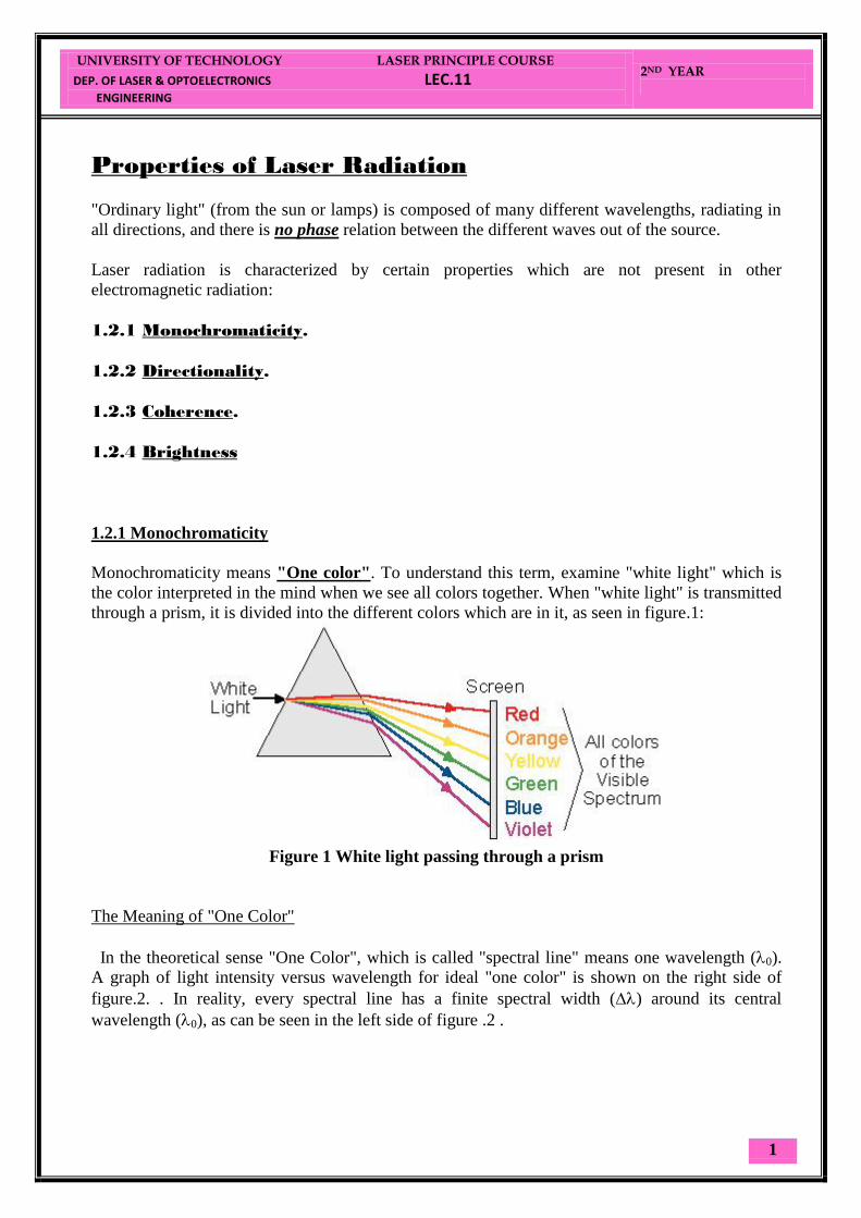
Monochromaticity means "One color". To understand this term, examine "white light" which is
the color interpreted in the mind when we see all colors together. When "white light" is transmitted
through a prism, it is divided into the different colors which are in it, as seen in figure.1:
Figure 1 White light passing through a prism
The Meaning of "One Color"
In the theoretical sense "One Color", which is called "spectral line" means one wavelength (0).
A graph of light intensity versus wavelength for ideal "one color" is shown on the right side of
figure.2. . In reality, every spectral line has a finite spectral width () around its central
wavelength (0), as can be seen in the left side of figure .2 .

UNIVERSITY OF TECHNOLOGY LASER PRINCIPLE COURSE
DEP. OF LASER & OPTOELECTRONICS LEC.11
ENGINEERING
2ND YEAR
2
Figure .2: Bandwidth of laser radiation in Theory and in Reality
1.2.2. Directionality
Radiation comes out of the laser in a certain direction, and spreads at a defined divergence angle
() (see figure .3 and example 1.2).This angular spreading of a laser beam is very small compared
to other sources of electromagnetic radiation, and described by a small divergence angle (of the
order of milli-radians).
In figure.3, a comparison is made between the radiation out of a laser, and the radiation out of a
standard lamp.
Figure .3: comparison between the light out of a laser, and the light out of an incandescent
lamp
Divergence Angle
Divergence Angle is the full angle of opening of the beam. (Some books use half of this angle as
divergence angle). The relation between radians and degrees is given by:
3600
= 2 Radians
1 Radian = 57.30,
1 milli-Radian = 1 mrad = 0.0570.
Using the relation between minutes and degrees: 10=60’, we get:
1 mrad = 0.057*60’ 3.5’
UNIVERSITY OF TECHNOLOGY LASER PRINCIPLE COURSE
DEP. OF LASER & OPTOELECTRONICS LEC.11
ENGINEERING
2ND YEAR
3
Since laser radiation divergence is of the order of milli-radians, the beam is almost parallel, and
laser radiation can be send over long distances.
We shall see later, how a laser beam was sent to the moon, and returned to Earth to measure the
distance between Earth and the moon with accuracy of tens of centimeters.
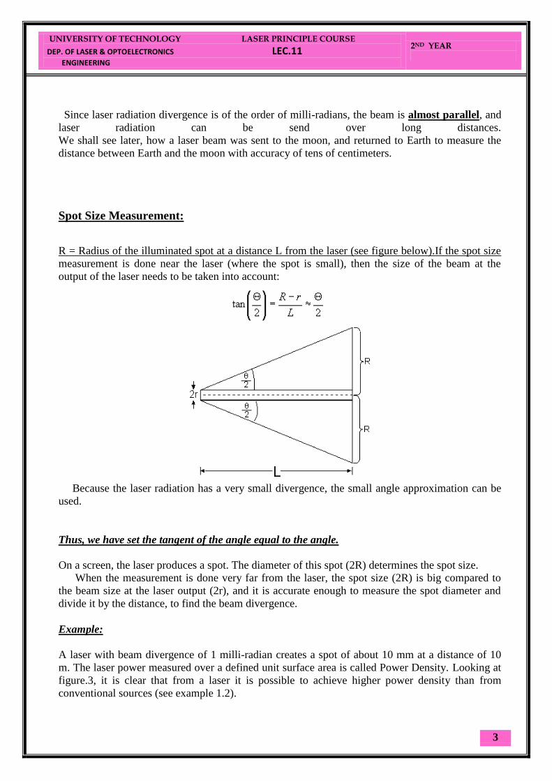
Spot Size Measurement:
R = Radius of the illuminated spot at a distance L from the laser (see figure below).If the spot size
measurement is done near the laser (where the spot is small), then the size of the beam at the
output of the laser needs to be taken into account:
Because the laser radiation has a very small divergence, the small angle approximation can be
used.
Thus, we have set the tangent of the angle equal to the angle.
On a screen, the laser produces a spot. The diameter of this spot (2R) determines the spot size.
When the measurement is done very far from the laser, the spot size (2R) is big compared to
the beam size at the laser output (2r), and it is accurate enough to measure the spot diameter and
divide it by the distance, to find the beam divergence.
Example:
A laser with beam divergence of 1 milli-radian creates a spot of about 10 mm at a distance of 10
m. The laser power measured over a defined unit surface area is called Power Density. Looking at
figure.3, it is clear that from a laser it is possible to achieve higher power density than from
conventional sources (see example 1.2).
UNIVERSITY OF TECHNOLOGY LASER PRINCIPLE COURSE
DEP. OF LASER & OPTOELECTRONICS LEC.11
ENGINEERING
2ND YEAR
4
This is the reason why a 5 [mW] laser radiation is considered dangerous, and the light out of a
100 W incandescent lamp is not!!!
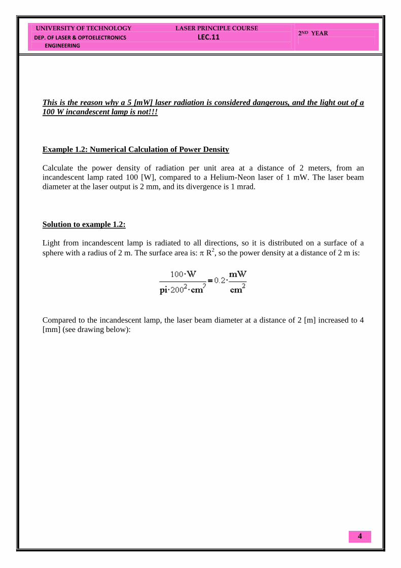
Example 1.2: Numerical Calculation of Power Density
Calculate the power density of radiation per unit area at a distance of 2 meters, from an
incandescent lamp rated 100 [W], compared to a Helium-Neon laser of 1 mW. The laser beam
diameter at the laser output is 2 mm, and its divergence is 1 mrad.
Solution to example 1.2:
Light from incandescent lamp is radiated to all directions, so it is distributed on a surface of a
sphere with a radius of 2 m. The surface area is: R2, so the power density at a distance of 2 m is:
Compared to the incandescent lamp, the laser beam diameter at a distance of 2 [m] increased to 4
[mm] (see drawing below):

UNIVERSITY OF TECHNOLOGY LASER PRINCIPLE COURSE
DEP. OF LASER & OPTOELECTRONICS LEC.12
ENGINEERING
2ND YEAR
1
Because the laser radiation has a very small divergence, the small angle approximation can be
used.
Thus, we have set the tangent of the angle equal to the angle.
On a screen, the laser produces a spot. The diameter of this spot (2R) determines the spot size.
When the measurement is done very far from the laser, the spot size (2R) is big compared to
the beam size at the laser output (2r), and it is accurate enough to measure the spot diameter and
divide it by the distance, to find the beam divergence.
Example:
A laser with beam divergence of 1 milli-radian creates a spot of about 10 mm at a distance of 10
m. The laser power measured over a defined unit surface area is called Power Density. Looking at
figure.3, it is clear that from a laser it is possible to achieve higher power density than from
conventional sources (see example 1.2).
This is the reason why a 5 [mW] laser radiation is considered dangerous, and the light out of a
100 W incandescent lamp is not!!!
Example 1.2: Numerical Calculation of Power Density
Calculate the power density of radiation per unit area at a distance of 2 meters, from an
incandescent lamp rated 100 [W], compared to a Helium-Neon laser of 1 mW. The laser beam
diameter at the laser output is 2 mm, and its divergence is 1 mrad.

UNIVERSITY OF TECHNOLOGY LASER PRINCIPLE COURSE
DEP. OF LASER & OPTOELECTRONICS LEC.12
ENGINEERING
2ND YEAR
2
Solution to example 1.2:
Light from incandescent lamp is radiated to all directions, so it is distributed on a surface of a
sphere with a radius of 2 m. The surface area is: R2, so the power density at a distance of 2 m is:
Compared to the incandescent lamp, the laser beam diameter at a distance of 2 [m] increased to 4
[mm] (see drawing below):
R = 2.1 mm = 0.2 cm
The power density of the laser radiation is:
When calculating radiation power in the visible spectrum (used for illumination) the low
efficiency of the incandescent lamp must be considered (A 100 W lamp emits only 1-3 W of
visible radiation and all the rest is in the infrared spectrum).
At a distance of 2 m from the radiation source, the power density of the laser radiation is 4 times
higher than from the lamp, although the power from the lamp is 5 times the original power of the
laser.
UNIVERSITY OF TECHNOLOGY LASER PRINCIPLE COURSE
DEP. OF LASER & OPTOELECTRONICS LEC.12
ENGINEERING
2ND YEAR
3
1.2.3 Coherence
Since electromagnetic radiation is a wave phenomenon, every electromagnetic wave can be
described as a sum (superposition) of sine waves as a function of time.
From wave theory we know that every wave is described by a wave function:
y = Acos (t+)
A=Amplitude.
= 2 =Angular Frequency.
= Initial Phase of the wave (Describe the starting point in time of the oscillation).
(t+) = Phase of the wave.
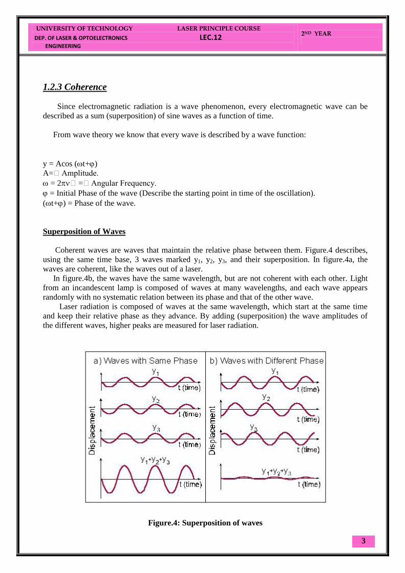
Superposition of Waves
Coherent waves are waves that maintain the relative phase between them. Figure.4 describes,
using the same time base, 3 waves marked y1, y2, y3, and their superposition. In figure.4a, the
waves are coherent, like the waves out of a laser.
In figure.4b, the waves have the same wavelength, but are not coherent with each other. Light
from an incandescent lamp is composed of waves at many wavelengths, and each wave appears
randomly with no systematic relation between its phase and that of the other wave.
Laser radiation is composed of waves at the same wavelength, which start at the same time
and keep their relative phase as they advance. By adding (superposition) the wave amplitudes of
the different waves, higher peaks are measured for laser radiation.
Figure.4: Superposition of waves

UNIVERSITY OF TECHNOLOGY LASER PRINCIPLE COURSE
DEP. OF LASER & OPTOELECTRONICS LEC.12
ENGINEERING
2ND YEAR
4

UNIVERSITY OF TECHNOLOGY LASER APPLICATION COURSE
DEP. OF LASER & OPTOELECTRONICS LEC.13
ENGINEERING
4ND YEAR
1
Where (df fD: is directional sensibility frequency = FS)
In LDV mostly used[4]
:
1. HeNe laser: high frequency stabilizer.
2. Argon laser: for more power required.
3. CO2 laser: measurement at large distance approached a kilometer or so.
Applications
1. Measurements of the velocity of blood flow.
2. Measurements in wind tunnels.
3. Industrial: vibration testing on car bodies
4. Telecommunication: analysis of vibration by wind load of parabolic antennas
on towers
Advantages:
1. Non-invasive measurement.
2. Very high precision.
Example12[4]
By using LDV with HeNe laser, estimate the speed and direction
of motion for a car if the Bragg frequency df = 40MHz & directional
sensibility frequency FS = 103MHz.
Solution:
df fD = FS 40 + fD = 103 fD = 103 – 40 = 63MHz
1
96
.209332.192
108.6321063
2
smf
V D

UNIVERSITY OF TECHNOLOGY LASER APPLICATION COURSE
DEP. OF LASER & OPTOELECTRONICS LEC.13
ENGINEERING
4ND YEAR
2
3.5 Laser Beam Printer (LBP)[13]
Shown in figure (3.7) is a simple diagram of a laser printer, and the main parts
of it as show below:
A. The Laser Scanning Assembly:
1. The laser:
a- HeNe laser (632.8nm):
1. Need an external modulator.
2.Very small divergence angle (need a single lens to focus it beam to the
required spot size).
b- Diode laser (700 nm) :
1. No need to external modulator (is built-in with the power supply).
2. Need more lens to focus it beam to the required spot size (wide beam
divergence).
2. The Modulator: Both Acousto-Optic & Electro-Optic modulator are used, The
light beam from the laser, proceeds through a modulator, which impresses the
data onto the beam in the form of intensity variations. The modulated beam
then passes to the deflector.
3. The Deflector: which it scans the beam across the photosensitive media. The
laser beam is reflected from the surface of a rotating polygonal mirror. This
scans the beam along the axis of the photoconductive drum (X-direction).
Rotation of the drum moves the scan down the surface of the photoconductor in
Y-direction. The result is a raster scan of the drum surface.
UNIVERSITY OF TECHNOLOGY LASER APPLICATION COURSE
DEP. OF LASER & OPTOELECTRONICS LEC.13
ENGINEERING
4ND YEAR
3
B. The Cartridge Assembly:
1.The Drum: The drum used in the laser printer is a photoconductive sandwich
applied to an aluminum cylinder. The sandwich consist of an aluminum layer
on which there is a cadmium-sulphide (CdS) photo-conductive layer.
2.The Toner: mixture of small black plastic particles known as toner with larger
iron based particles known as carrier.
3. Charge Corona:
a- Primary Corona: Which applied a high positive charge to the drum.
b- Transfer Corona: Which applied a high positive charge to the paper.
4. The Developer: The developer station contain a toner mixer is transported to the
drum on a magnetic brush which generates a toner cloud at the drum surface
with negatively charged. The charged powder adheres only to those areas of the
surface that contain the positively charged image. At this point, the image
becomes visible.
C. The Fusing Assembly: the fuser contain a 3 components:
1. Halogen heating lamp. 2. Teflon coating roller. 3. Pressure roller.
The halogen lamp heats the fusing roller to 350F before the toner is melted onto
the paper by the fuser unit.

UNIVERSITY OF TECHNOLOGY LASER APPLICATION COURSE
DEP. OF LASER & OPTOELECTRONICS LEC.13
ENGINEERING
4ND YEAR
4
UNIVERSITY OF TECHNOLOGY LASER APPLICATION COURSE
DEP. OF LASER & OPTOELECTRONICS LEC.14
ENGINEERING
4ND YEAR
1
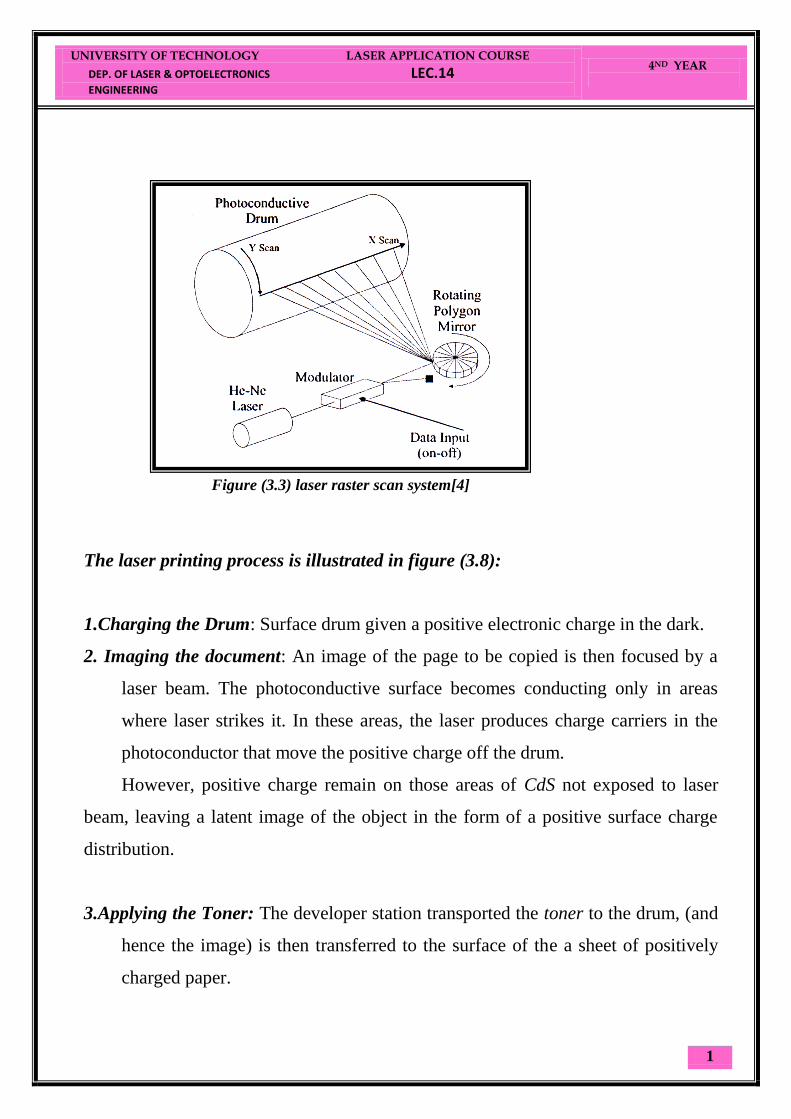
The laser printing process is illustrated in figure (3.8):
1.Charging the Drum: Surface drum given a positive electronic charge in the dark.
2. Imaging the document: An image of the page to be copied is then focused by a
laser beam. The photoconductive surface becomes conducting only in areas
where laser strikes it. In these areas, the laser produces charge carriers in the
photoconductor that move the positive charge off the drum.
However, positive charge remain on those areas of CdS not exposed to laser
beam, leaving a latent image of the object in the form of a positive surface charge
distribution.
3.Applying the Toner: The developer station transported the toner to the drum, (and
hence the image) is then transferred to the surface of the a sheet of positively
charged paper.
Figure (3.3) laser raster scan system[4]

UNIVERSITY OF TECHNOLOGY LASER APPLICATION COURSE
DEP. OF LASER & OPTOELECTRONICS LEC.14
ENGINEERING
4ND YEAR
2
4.Transfer the Toner to the paper: The toner (and hence the image) is then
transferred to the surface of the a sheet of positively charged paper. Finally, the
toner is “fixed” to the surface of the paper as the toner melt while passing high
temperature rollers.
3.6 Digital Optical Storage of Information
Digital system operates on two states (Binary system) which are defined as "1"
or "0". Each binary digit is called "Bit". The basic storage unit in a computer is
composed of 8 Bits, and called "Byte". The more useful units are[1]
:
KB = 1,000 Bytes = Kilo-Byte,
MB = 106 Bytes = Mega-Byte,
GB = 109 Bytes = Giga-Byte.
TB = 1012
Bytes = Tera-Byte.
Figure (3.4) the main Printing Process [3]

UNIVERSITY OF TECHNOLOGY LASER APPLICATION COURSE
DEP. OF LASER & OPTOELECTRONICS LEC.14
ENGINEERING
4ND YEAR
3
To get a feeling about orders of magnitude of digital storage: A book of 200
pages of plain text is stored in 400-800 KB
3.6.1 The Optical Storage Techniques
Till now there are three techniques of optical storage (CD, DVD, Blu-ray), this
section are going to guide the light on the main differences between these
techniques, as shown in table below:
Technique Acronym Laser (nm) Storage Capacity Track Space
(m) 1-Layer 2-Layer
CD Compact Disk IR 780 700 MB ----- 1.6
DVD Digital Video Disk Red 650 4.7 GB 9 GB 0.74
BD Blu-ray Disk Blue 405 25 GB 50 GB 0.3
Fig.3.5 the optical storage techniques

UNIVERSITY OF TECHNOLOGY LASER APPLICATION COURSE
DEP. OF LASER & OPTOELECTRONICS LEC.14
ENGINEERING
4ND YEAR
4
3.6.2 The Recording Medium
The information is recorded along a continuous spiral track, which contains
Micro-pits on a plastic material with a metallic coating as shown in figure 3.6.
UNIVERSITY OF TECHNOLOGY LASER APPLICATION COURSE
DEP. OF LASER & OPTOELECTRONICS LEC.15
ENGINEERING
4ND YEAR
1
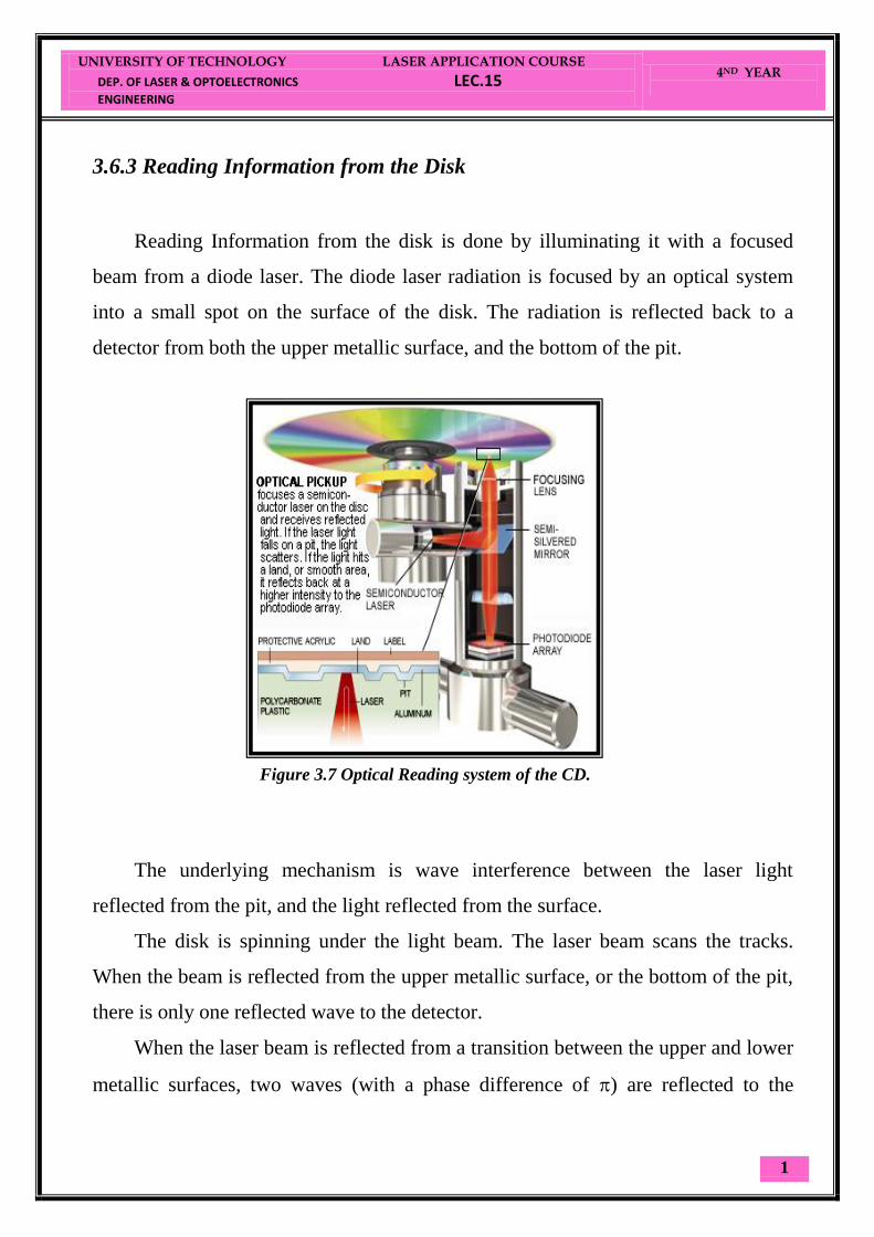
3.6.3 Reading Information from the Disk
Reading Information from the disk is done by illuminating it with a focused
beam from a diode laser. The diode laser radiation is focused by an optical system
into a small spot on the surface of the disk. The radiation is reflected back to a
detector from both the upper metallic surface, and the bottom of the pit.
The underlying mechanism is wave interference between the laser light
reflected from the pit, and the light reflected from the surface.
The disk is spinning under the light beam. The laser beam scans the tracks.
When the beam is reflected from the upper metallic surface, or the bottom of the pit,
there is only one reflected wave to the detector.
When the laser beam is reflected from a transition between the upper and lower
metallic surfaces, two waves (with a phase difference of ) are reflected to the
Figure 3.7 Optical Reading system of the CD.

UNIVERSITY OF TECHNOLOGY LASER APPLICATION COURSE
DEP. OF LASER & OPTOELECTRONICS LEC.15
ENGINEERING
4ND YEAR
2
detector. These two waves interfere destructively, (cancel each other) and the
detector reads no reflected signal as shown in figure 3.8.
When the detector "sees" a transition between the pit and the upper surface, the
detector reads "one". Otherwise the reflection is from metallic surface, and there is
no transition (no destructive interference), so the reading is "zero".
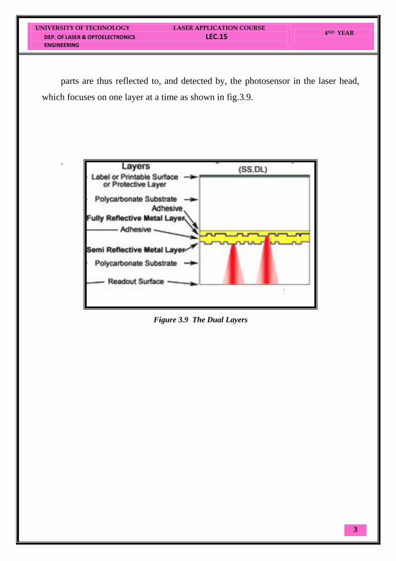
3.6.4 The Dual Layer
Optical disk can be manufactured with two reflective metal layers that allow the
laser to read data from both layers using one side of the disc. These “double layered”
disk’s provide up to two times the capacity for content (video, audio, computer
applications) as do “single-layered” disk’s.
The laser beam must pass through a semi-reflective metal layer to read data
from a fully reflective layer. The outer metal layer (silicon, gold, or silver alloy) is
semi-reflective; that is, it reflects back some of the laser beam and allows some of it
to pass through to a fully reflective layer (aluminum) and then reflect back. Both
pit
Fig.3.8 shows the destructive interference
UNIVERSITY OF TECHNOLOGY LASER APPLICATION COURSE
DEP. OF LASER & OPTOELECTRONICS LEC.15
ENGINEERING
4ND YEAR
3
parts are thus reflected to, and detected by, the photosensor in the laser head,
which focuses on one layer at a time as shown in fig.3.9.
.
Figure 3.9 The Dual Layers