the electromagnetically sustained rhodes piano · the electromagnetically sustained rhodes piano...
TRANSCRIPT
The Electromagnetically Sustained Rhodes Piano
Greg ShearMedia Arts & Technology (MAT)
University of CaliforniaSanta Barbara, CA 93106
Matthew WrightCREATE/MAT
University of CaliforniaSanta Barbara, CA 93106
ABSTRACTThe Electromagnetically Sustained Rhodes Piano is an aug-mentation of the original instrument with additional con-trol over the amplitude envelope of individual notes. Thisincludes slow attacks and infinite sustain while preservingthe familiar spectral qualities of this classic electromechan-ical piano. These additional parameters are controlled withaftertouch on the existing keyboard, extending standardpiano technique. Two sustain methods were investigated,driving the actuator first with a pure sine wave, and secondwith the output signal of the sensor. A special isolationmethod effectively decouples the sensors from the actuatorsand tames unruly feedback in the high-gain signal path.
KeywordsRhodes, keyboard, electromagnetic, sustain, augmented in-strument, feedback, aftertouch
1. INTRODUCTIONThe motivation behind this project comes from composi-tional experiments in the recording studio editing Rhodespiano samples in Pro Tools to create swelling and sustain-ing effects impossible to play on the original instrument. Wedesire these new affordances in a live performance settingcontrolled through the existing keyboard interface, extend-ing standard piano technique all while leaving the originalfunctionality of the instrument intact.
We present a novel system that offers limited control overthe amplitude envelope of a Fender Rhodes electric piano,including infinite sustain, controlled by aftertouch on theexisting keyboard interface. A primary design goal was topreserve the timbral qualities of the original electromechan-ical instrument, which rely on both the tone source (thevibrating tine) and the sensor (the magnetic pickup). Withthe addition of some circuitry and electromagnetic actua-tors to the existing electronics, we have extended the affor-dances of the instrument without compromising its originalfunctionality.
2. EXISTING INSTRUMENTS2.1 The EBowThe EBow is a device designed for sustaining vibrations inferromagnetic guitar strings through positive feedback [2]
Permission to make digital or hard copies of all or part of this work forpersonal or classroom use is granted without fee provided that copies arenot made or distributed for profit or commercial advantage and that copiesbear this notice and the full citation on the first page. To copy otherwise, torepublish, to post on servers or to redistribute to lists, requires prior specificpermission and/or a fee.NIME’11, 30 May–1 June 2011, Oslo, Norway.Copyright remains with the author(s).
and is controlled simply by moving the device toward oraway from the strings. The EBow uses one sensing coil togenerate a signal that drives a second coil which in turn ex-erts a time-varying magnetic force on the string supportingits oscillation. Permanent magnetic cores in each coil tem-porarily magnetize the ferromagnetic string greatly increas-ing efficiency of the actuator and allowing for both attrac-tive and repulsive forces between the actuator and string.Without this magnetization, the actuator would exert onlyan attractive force on the string, effectively rectifying theactuator signal and adding undesirable high frequency dis-tortion.
We found that direct magnetic coupling between the sen-sor and actuator coils leads to uncontrollable feedback in oursystem. There appears to be no compensation for this effectin the referenced EBow patent so we assume the EBow didnot suffer from the same complications given the positionand orientation of the coils and the amount of gain in thefeedback circuit. Besides the compensation for this directmagnetic coupling, our electronics system is most similar tothat of the EBow.
2.2 The Electromagnetically-Prepared PianoThe Electromagnetically-Prepared Piano [1] is an acousticpiano with electromagnetic actuators placed above certainstrings. Each actuator is driven with an arbitrary audio sig-nal (the creators suggest pure sine waves, orchestral sam-ples, noise, etc.) through a standard audio amplifier andthe strings filter the signal before acoustic amplification viathe soundboard. Control is achieved through software suchas Cycling 74’s Max/MSP [8] and the original key/hammeraction is left unaltered.
This differs from our system in that we drive the actuatorswith a signal generated by the vibrating mechanism thuscompleting a feedback loop. Furthermore, we control thesystem through pressure sensors retrofitted to the existingkeyboard interface.
2.3 The Magnetic Resonator PianoAndrew McPherson’s Magnetic Resonator Piano [4] inspiredour project and this is apparent in the similarity of our de-sign goals. He also uses mechanical-electrical feedback todrive the piano strings but his actuator signals are gener-ated through a much more complex system. A single piezo-electric sensor placed on the soundboard is the source forall of the actuators. This signal is distributed to a series ofindividually tuned bandpass filters that then drive phase-locked loops with adjustable delay to compensate for thepropagation time through the soundboard. He achieves con-trol through continuous sensing of each key with a modifiedMoog Piano Bar [5] and a complex mapping scheme of thiscontrol data to amplitude and spectral parameters for eachnote.
Proceedings of the International Conference on New Interfaces for Musical Expression, 30 May - 1 June 2011, Oslo, Norway
14
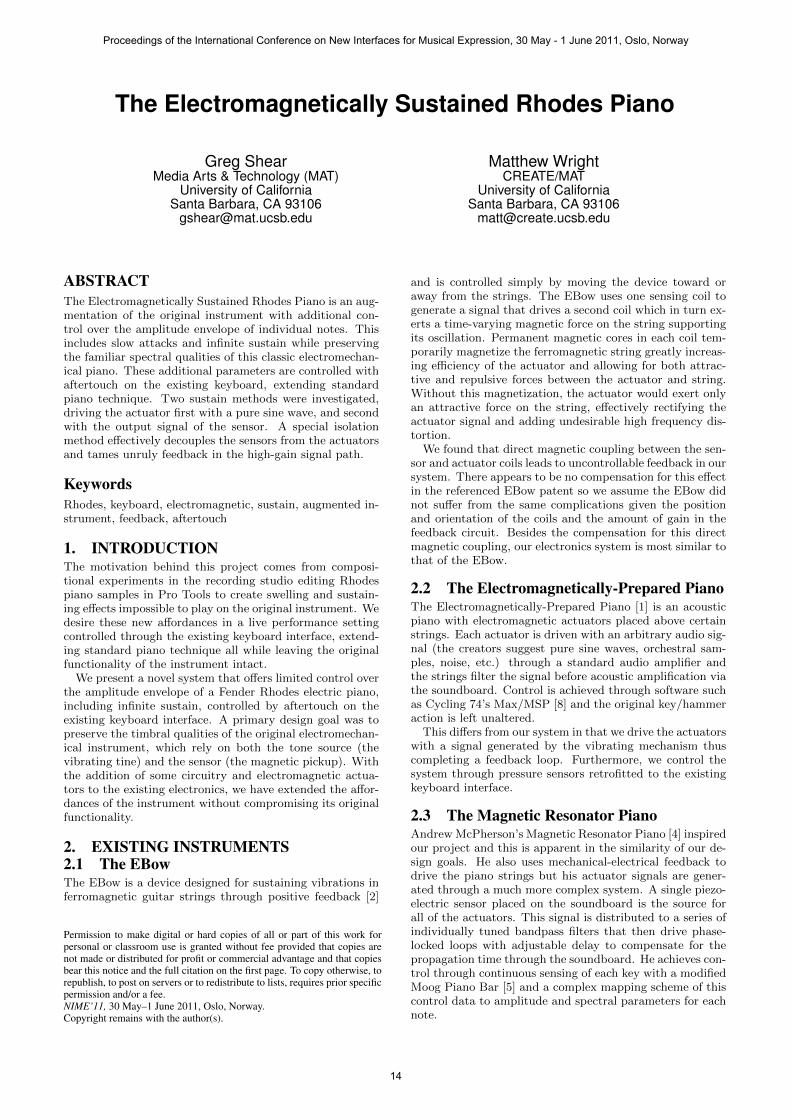
3. THE FENDER RHODESThe Fender Rhodes piano [6] is an electromechanical in-strument that uses a steel cantilever beam (the tine, seenin Figure 1) as its primary tone source. In each piano thereis one tine per note with fundamental vibrating frequenciesranging from 27 Hz to 4.2 kHz on the 88-key model, and41 Hz to 2.6 kHz on the 73-key model. Each tine is sensedby a dedicated passive magnetic pickup: vibration in thetine disturbs the magnetic field through a coil of wire thusgenerating an electrical signal. The average1 of the signalsfrom each sensor is present at the output jack of the instru-ment for amplification. Similar to an acoustic piano, thetine is struck by a hammer and damped by a felt pad. Thetuning spring is a stiff wire wrapped around the free end ofthe tine that adds mass and allows for adjustment of thefundamental frequency.
3.1 The Tine and Tonebar
Figure 1: Tone generator assembly [6].
Each tine is paired with a tonebar and together they be-have as an asymmetrical tuning fork. Although their funda-mental frequencies are different, the tonebar stores energyfrom the initial hammer strike and helps to sustain vibra-tions in the tine [6].
Unlike a piano string, which is fixed at both ends andvibrates with overtones at near integer multiples of the fun-damental, the tine is free at one end and has a decidedlyinharmonic overtone series with the first overtone at a non-integer multiple several times higher than the fundamen-tal (depending on the physical parameters of the tine) [7].These inharmonic overtones give the Rhodes piano a some-what bell-like timbre.
The tine itself is cylindrical (except near the base) with adiameter of 1.5 mm and lengths ranging from 18 mm to 157mm. The free end of the tine swings up and down reachinga displacement of up to 50 mm for the longest tine, whileshortest tine reaches a displacement of less than 1 mm.
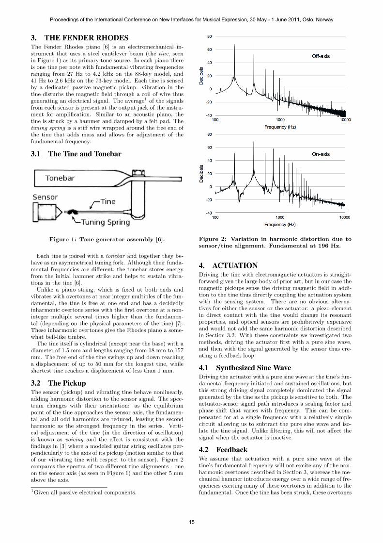
3.2 The PickupThe sensor (pickup) and vibrating tine behave nonlinearly,adding harmonic distortion to the sensor signal. The spec-trum changes with their orientation: as the equilibriumpoint of the tine approaches the sensor axis, the fundamen-tal and all odd harmonics are reduced, leaving the secondharmonic as the strongest frequency in the series. Verti-cal adjustment of the tine (in the direction of oscillation)is known as voicing and the effect is consistent with thefindings in [3] where a modeled guitar string oscillates per-pendicularly to the axis of its pickup (motion similar to thatof our vibrating tine with respect to the sensor). Figure 2compares the spectra of two different tine alignments - oneon the sensor axis (as seen in Figure 1) and the other 5 mmabove the axis.
1Given all passive electrical components.
Figure 2: Variation in harmonic distortion due tosensor/tine alignment. Fundamental at 196 Hz.
4. ACTUATIONDriving the tine with electromagnetic actuators is straight-forward given the large body of prior art, but in our case themagnetic pickups sense the driving magnetic field in addi-tion to the tine thus directly coupling the actuation systemwith the sensing system. There are no obvious alterna-tives for either the sensor or the actuator: a piezo elementin direct contact with the tine would change its resonantproperties, and optical sensors are prohibitively expensiveand would not add the same harmonic distortion describedin Section 3.2. With these constraints we investigated twomethods, driving the actuator first with a pure sine wave,and then with the signal generated by the sensor thus cre-ating a feedback loop.
4.1 Synthesized Sine WaveDriving the actuator with a pure sine wave at the tine’s fun-damental frequency initiated and sustained oscillations, butthis strong driving signal completely dominated the signalgenerated by the tine as the pickup is sensitive to both. Theactuator-sensor signal path introduces a scaling factor andphase shift that varies with frequency. This can be com-pensated for at a single frequency with a relatively simplecircuit allowing us to subtract the pure sine wave and iso-late the tine signal. Unlike filtering, this will not affect thesignal when the actuator is inactive.
4.2 FeedbackWe assume that actuation with a pure sine wave at thetine’s fundamental frequency will not excite any of the non-harmonic overtones described in Section 3, whereas the me-chanical hammer introduces energy over a wide range of fre-quencies exciting many of these overtones in addition to thefundamental. Once the tine has been struck, these overtones
Proceedings of the International Conference on New Interfaces for Musical Expression, 30 May - 1 June 2011, Oslo, Norway
15

Figure 3: Sustainer circuit with feedback.
Table 1: Variable key.Velocity of tine v
Electromotive force EVoltage across sensor, output amp Vs,Vo
Current through actuator IaComplex impedance of output stage ZOut
Circuit gain GPhase shift φ
Magnetic field produced by sensor, actuator Bs,BaMagnetic flux through sensor coil ΦB
Magnetic moment of tine mForce on tine F
Distance from actuator of point on axis xNumber of turns of wire in sensor, actuator Ns,Na
Cross-sectional area of actuator A
should be present in the output signal and will self-sustainin the feedback loop.
4.2.1 Theory and Basic Equations For ControlWe assume the vibrating tine is a damped harmonic oscil-lator that experiences a damping force proportional to itsvelocity v. To compensate for this and sustain oscillationsindefinitely, the actuator must exert a force on the tine pro-portional to −v. The following equations (with variablesdefined in Table 1) show how the feedback system achievesthis goal.
d
dtΦB ∝ v · ∇Bs (1)
Vs = E = −Nsd
dtΦB (2)
Vo = GVs (3)
Ia =Vo
|ZOut|ejφ(4)
B ∝ NaIaA2
2(x2 +A2)32
(5)
F = ∇(m ·Ba) (6)
Equation (1) represents the relationship of magnetic fluxrate of change to velocity of the tine traveling through thenon-uniform magnetic field imposed by the sensor core. Equa-tion (2) is the special case of Faraday’s law for the EMFproduced in a coil of wire. This also equals the voltage pre-sented at the op-amp input assuming infinite input impedance.
Equation (3) shows the voltage gain through the circuit.Equation (4) shows the phase relationship φ between actu-ator current and voltage. Equation (5) shows the magneticfield produced by a current through a coil of wire, simplifiedfor the different magnetic permeabilities of the core and theair gap between the actuator and the tine. Equation (6)shows the force on the tine due to the magnetic field pro-duced by the actuator.
The phase shift φ introduced at the output stage reducesactuator efficiency, and with a shift of more than 90 theactuator begins to damp the tine. A constant current ampli-fier (seen in Figure 3) is used to minimize this phase shiftand Figure 4 shows the phase response curve. The theo-retical calculations ignore the amplifier’s output impedanceand this may account for some of the discrepancy with theexperimental data.
Figure 4: Phase response of constant current outputamplifier.
4.2.2 ImplementationAgain, direct magnetic coupling complicated early exper-iments as the high electrical signal gain far exceeded theattenuation of the magnetic field due to physical separa-tion between actuator and sensor. Subtracting the actu-ator signal out of the sensor signal was necessary to con-trol feedback; a second sensor with similar phase responseplaced near the fixed end of the tine (Figure 5) was usedto provide the subtraction signal. In this configuration, themovement of the tine is detected by only one sensor, butthe driving magnetic field is present at both sensors. Tak-ing the difference of the two signals substantially removes
Proceedings of the International Conference on New Interfaces for Musical Expression, 30 May - 1 June 2011, Oslo, Norway
16
the actuator component and isolates the tine component.Please note that the distortion described in Section 3.2 isan effect of the physical vibration of the tine with respectto the stationary sensor; therefore, since the actuator is alsostationary, no such distortion is imposed on the magneticsignal emitted by the actuator and received by the sensor.
Both sensors are original Rhodes piano pickups. The ac-tuator is approximately 600 turns of 30 AWG copper wirewound around a plastic sewing machine bobbin mounted ona steel core. DC resistance is about 170Ω for the sensorsand 11Ω for the actuator.
Figure 5: Actuator, two sensors, and tine.
5. PHYSICAL INTERFACEStraightworward aftertouch control is achieved with a pres-sure sensor (variable resistor) placed on the keybed. Thissensor has a resistance inversely related to applied pressureand is the input resistor on the second gain stage in thefeedback circuit (Figure 3). This configuration maps after-touch pressure to the rate of gain increase, within certainlimits. Indeed, high pressure will quickly increase the sig-nal through feedback to where the output amplifier clipsseverely and distorts. Decay time can be prolonged, butbecause our system (currently) lacks active damping thelower limit is governed by the natural decay of the tine.
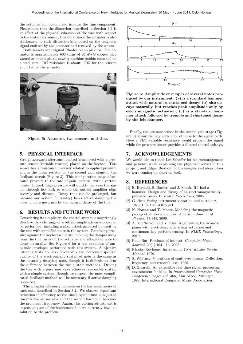
6. RESULTS AND FUTURE WORKConsidering its simplicity, the control system is surprisinglyeffective. A wide range of arbitrary amplitude envelopes canbe performed, including a slow attack achieved by excitingthe tine with amplified noise in the system. Removing pres-sure against the keybed while still holding the damper awayfrom the tine turns off the actuator and allows the note todecay naturally. See Figure 6 for a few examples of am-plitude envelopes performed with this system. Subjectivelistening tests are also favorable - the perceived spectralquality of the electronically sustained note is the same asthe naturally decaying note, though it is difficult to hearthe difference between the two sustain methods. Drivingthe tine with a pure sine wave achieves reasonable sustainwith a simple system, though we suspect the more compli-cated feedback method will be necessary if active dampingis desired.
The actuator efficiency depends on the harmonic series ofeach note described in Section 3.2. We observe significantreduction in efficiency as the tine’s equilibrium is adjustedtowards the sensor axis and the second harmonic becomesthe prominent frequency. Again, this voicing adjustment isimportant part of the instrument but we currently have nosolution to the problem.
Figure 6: Amplitude envelopes of several notes pro-duced by our instrument: (a) is a standard hammerattack with natural, unsustained decay; (b) also de-cays naturally, but reaches peak amplitude only byelectromagnetic actuation; (c) is a standard ham-mer attack followed by tremolo and shortened decayby the felt damper.
Finally, the pressure sensor in the second gain stage (Fig-ure 3) unsurprisingly adds a lot of noise to the signal path.Here a FET variable resistance would protect the signalwhile the pressure sensor provides a filtered control voltage.
7. ACKNOWLEDGEMENTSWe would like to thank Les Schaffer for his encouragementand patience while explaining the physics involved in thisproject, and Edgar Berdahl for his insights and ideas whenwe were coming up short on both.
8. REFERENCES[1] E. Berdahl, S. Backer, and J. Smith. If I had a
hammer: Design and theory of an electromagnetically-prepared piano. In ICMC Proceedings, 2005.
[2] G. Heet. String instrument vibration and sustainer,1978. U.S. Pat. 4,075,921.
[3] N. Horton and T. Moore. Modeling the magneticpickup of an electric guitar. American Journal ofPhysics, 77:144, 2009.
[4] A. McPherson and Y. Kim. Augmenting the acousticpiano with electromagnetic string actuation andcontinuous key position sensing. In NIME Proceedings,2010.
[5] PianoBar. Products of interest. Computer MusicJournal, 29(1):104–113, 2005.
[6] Rhodes Keyboard Instruments USA. Rhodes ServiceManual, 1979.
[7] S. Whitney. Vibrations of cantilever beams: Deflection,frequency, and research uses, 1999.
[8] D. Zicarelli. An extensible real-time signal processingenvironment for Max. In International Computer MusicConference, pages 463–466, Ann Arbor, Michigan,1998. International Computer Music Association.
Proceedings of the International Conference on New Interfaces for Musical Expression, 30 May - 1 June 2011, Oslo, Norway
17