the end-bearing capacity of piles penetrating into...
TRANSCRIPT

Zhang, C. et al. Geotechnique [http://dx.doi.org/10.1680/geot.11.P.117]
1
The end-bearing capacity of piles penetrating into crushable soils
C. ZHANG�, G. D. NGUYEN� and I . EINAV�
A new formula is proposed for the end-bearing capacity of piles penetrating into crushable soils. Theformula is based on a breakage mechanics model that accounts for the evolution of the grain sizedistribution (GSD) due to grain crushing with only physically meaningful parameters. The model isintegrated using the finite-element method to study the penetration problem. Predictions of GSDssurrounding piles and pile end-bearing capacities are validated against experiments. Next, a parametricstudy is carried out to quantify the effects of grain crushing on the bearing capacity, and then toestablish the formula. The predictive capability of the new formula is highlighted against predictionsby previous formulae, which highlights its superior origins.
KEYWORDS: bearing capacity; constitutive relations; numerical modelling; particle crushing/crushability;piles
INTRODUCTIONConventional bearing capacity equations predict increasingresistance with increasing friction angle (e.g. Terzaghi,1943). Accordingly, given the relatively high friction angleof calcareous sand, it can be expected that its resistanceagainst pile penetration would be high. However, in suchcrushable soils the bearing capacity is much lower thanexpected from the conventional equations (Poulos & Chua,1985; Golightly & Hyde, 1988; Yu, 2000; Yamamoto et al.,2009). For example, it has been shown experimentally thatfor comparable tip resistances, pile displacements in highlycrushable materials are much larger than in non-crushablesoils (Kuwajima et al., 2009). This is because grain crushinghelps the soil to accommodate the new volumetric intrusionby the pile. The result is an overall reduction of the totalvolume, defined by the soil compressibility. In crushablesands, the compressibility is governed by the way the GSDevolves, as observed experimentally (Datta et al., 1979) andrationalised theoretically (Einav, 2007a). The GSD influencesthe strength and stress–strain behaviour of the soil (Hardin,1985; Lade et al., 1996), and subsequently affects the end-bearing capacity of the pile. For example, using geotechnicalcentrifuge tests of a model pile driven into crushable soils,McDowell & Bolton (2000) noticed that the resistance topenetration by well-graded soils is higher than that byuniformly poorly graded soils.
The importance of soil crushability for the design andconstruction of pile foundations was highlighted from apractical standpoint (Datta et al., 1980; Poulos & Chua,1985; Alba & Audibert, 1999). Various laboratory and insitu field tests (e.g. pile load test, cone penetration test(CPT), and pressuremeter test (PMT)) have been carried outto obtain relevant experimental information and determinepile end-bearing capacities (Foray et al., 1999; Joer et al.,1999). Simple models of cavity expansion were also used toassess end-bearing capacities, and Vesic (1973b) has usedthis approach to derive an end-bearing capacity equation forpiles dependent on the confining pressure and soil compres-sibility. The applicability of his derived formula has beennoted for both shallow footings (Poulos, 1989) and piles(Yasufuku & Hyde, 1995) residing in crushable soils, at least
when compared with results yielded by Terzaghi’s originalequation (Terzaghi, 1943). The outcome, however, does notexplain why the bearing capacity varies with crushabilityand variations in the GSDs. Another formula relating theend-bearing capacity to the cavity expansion pressure wasdeveloped by Yasufuku & Hyde (1995). Their proposedequation requires the introduction of a so-called ‘secantfriction angle’ in order to capture the observed pressuredependence of the end-bearing capacity; the secant frictionangle is not a fundamental soil property, however, and there-fore cannot explain why the bearing capacity varies withcrushability and GSDs. More recently Russell & Khalili(2002) employed the cavity expansion approach to study theeffect of grain crushing on CPT and PMT model tests,which required an assumed relation between the grain crush-ing and the compressibility by way of the void ratio, but thisrelation was empirical, and thus cannot respond to variationin the tested material and its initial GSD.
The purpose of this paper is to establish a more complete,rigorous and reliable bearing capacity equation for pilespenetrating into sand that considers the grain crushability aswell as other critical factors (e.g. GSD, friction coefficient,and elastic stiffness). To achieve this purpose the problem isanalysed using the micromechanics-based continuum theoryof breakage mechanics (Einav, 2007a, 2007b, 2007c, 2007d).This theory rigorously takes into account the effects of theevolving cumulative GSD due to grain crushing on thematerial behaviour by incorporating an internal breakagevariable B within the framework of thermodynamics. Here asimple constitutive model of breakage mechanics is imple-mented (the so-called ‘student model’ of breakage mech-anics, as proposed by Einav (2007d)) into the finite-elementmethod (FEM). This FEM model is defined to represent apile penetrating into crushable soils, which thus enables usto capture failures dependent on both grain crushing andfriction. Also, given the ability to find B anywhere in spaceand time, the model can also track the evolution of theGSDs surrounding the pile during its penetration. Comparingwith experiments, it is shown that the FEM model predictswell the pile end-bearing capacities, evolving GSDs and soildeformations. On this basis a parametric study is thencarried out to establish the new formula for the end-bearingcapacity of piles. The formula is robust and versatile, andcan capture the effects of variability of many physicalparameters, including the pressure, the initial GSD, thecritical comminution pressure that defines the onset of
Manuscript received 14 September 2011; revised manuscript accepted18 July 2012.Discussion on this paper is welcomed by the editor.� School of Civil Engineering, University of Sydney, Australia.
yielding, the friction coefficient and the elastic stiffness ofthe material. A brief discussion on the role of the initialdensity (through porosity) will also be provided.
It is important to acknowledge previous works that impli-citly introduce the effects of grain crushing into constitutivemodels (Daouadji et al., 2001; Muir Wood & Maeda, 2007;Daouadji & Hicher, 2009), typically by extending the critical-state framework of plasticity. Although these contributionsemphasise the need to link stress–strain relations to graincrushing, they have done this without considering thermody-namic admissibility, and have missed the kinematics linked tothe creation of surface area (i.e. missed aspects of strainevolution) and its conjugated energetics (i.e. missed aspectsof stress evolution). The GSD in these works was thereforenot an independent state variable, and thus those models relyon heavy use of complex experimental programmes forcurve-fitting breakage to pressure (notice, however, that therelation between breakage and pressure is physically path-dependent). Distinguished from these works, here the modelis thermodynamically admissible; it is physically path-dependent; and it embodies the balance between the kineticsof surface creation and the energy required for surfacealterations in confined granular materials (Einav, 2007c).
A CONSTITUTIVE MODEL BASED ON BREAKAGEMECHANICS THEORY
The cumulative GSD (sieve curve) is one of the mostwidely measured properties in soil mechanics and geotechni-cal engineering. Its importance in governing the mechanicalresponse of soils has been well acknowledged (Lade et al.,1996; McDowell & Bolton, 2000). However, only recentlythis property was consistently considered to formulate consti-tutive models, through the breakage mechanics theory ofEinav (2007a, 2007b). In this theory a micromechanics-basedinternal variable, called breakage, B, was introduced in a waythat makes it possible to predict the evolving GSD. Theexplicit connection between the micromechanics of graincrushing and macroscopic model behaviour means that betterprediction of mechanical response is achieved with fewerphysically identifiable model parameters. Consequently, ex-perimental observations are better explained and new phe-nomena predicted, such as the permeability reduction in suchsoils (Nguyen & Einav, 2009, Zhang et al., 2010). In thefollowing, first a few key points of breakage mechanics theoryare listed, followed by a brief explanation of the simple‘student model’ of breakage mechanics. Readers are referredto earlier works by Einav (2007a, 2007b, 2007c, 2007d) for adescription of this theory and the simplest student model.
The problems in this paper depend on complexity arisingfrom two different sources: material complexity determinedby the constitutive model, and geometrical complexity deter-mined by the boundary conditions imposed in the FEM. Inthe authors’ opinion, it is not instructive to include all thecomplexity at once. This is the first reason why the linearelastic breakage model is used in this paper. The secondreason is the authors’ intention to derive formulae based ona limited number of parameters, which could be readilyunderstood by any practical engineer. Of course, materialcomplexity could be captured with more advanced breakagemodels. For example, Nguyen & Einav (2009) showed howpressure-dependent Hertzian elasticity could be incorporatedinto the formulation, and how this improves stress–strainpredictions. Furthermore, the use of porosity is also notintroduced directly in the current analysis, but Rubin &Einav (2011) solved this issue in the context of breakagemechanics. Finally, notice that the breakage variable, B, onlyweighs the proximity of the current GSD to the initial andultimate GSDs. Certainly, using a single evolutionary scalar
variable (B) to replace an evolutionary function (the GSD) isa simplification: for example, after shear path or compres-sion path, B might be the same, but the GSDs could bedifferent. The practical advantages of employing this ‘frac-tional breakage’ hypothesis have been highlighted by Einav(2007a), as a viable first step before refining the model.
In short, although the breakage model used in this paperis the simplest available, in the authors’ view this is practi-cally justifiable, since the boundary conditions of the ana-lysed problem are sufficiently complex. The integrated effectof assembling the contributions from all the various pointsin space is therefore as important as capturing accurately theconstitutive behaviour of each of these points. This is thesame reason why rigorous FEM analyses with simple con-stitutive models (e.g. Tresca, Mohr–Coulomb and Cam Clayelasto-plasticity) can still be relevant.
Breakage mechanics theory: key pointsThe rigour and novelty of the breakage mechanics theory
for crushable soils can be attributed to several key points.There are five key points relevant to the current paper, ashighlighted below (Einav, 2007a).
(a) Breakage, B, is introduced to predict the currentcumulative GSD by mass (F(x, B)) through a linearscaling between the initial (F0(x)) and ultimate cumula-tive GSDs (Fu(x)).
F x, Bð Þ ¼ 1� Bð Þ F0 xð Þ þ BFu xð Þ (1)
(b) The ultimate GSD, Fu(x), is associated with the criticalstate. In the current model this is done withoutincorporating effects of dilation as a competing phenom-enon to grain crushing in low stresses. However, asmodelled by Rubin & Einav (2011), introducing such aneffect into the breakage formulation helps to highlight therole of this competition in determining the non-uniquenessof the critical-state pressure–porosity relation in sand(evidenced experimentally, e.g. by Coop et al. (2004)).Although not absolutely necessary, it is practical toemploy a fractal power law Fu(x) (Sammis et al., 1986;McDowell et al., 1996; Ben-Nun & Einav, 2010). Notice,however, that although the model associates Fu(x) with thecritical state, this does not mean that this ultimate gradingshould always be reached after the pile has penetrated,thanks to the elastic rebound after the material points havepassed the pile’s tip.
(c) The specific elastic strain energy stored in larger grains isgreater than in smaller grains. To a first order this energyscales with the grains’ surface area. This assumption wasverified by Einav (2007a), using the discrete-elementmethod under isotropic loading conditions, and by Ben-Nun (2010) under cavity expansion, simple shear, andbiaxial test conditions. The basic reason for this(apparently) universal finding is that larger grains carrymore contacts in proportion to their larger surface.
(d ) Through statistical homogenisation, the macroscopicspecific elastic strain energy stored is the average ofsuch energies stored in the various size fractions,determined by the current GSD, F(x, B).
(e) Breakage dissipation from grain crushing is equal to theloss in the residual breakage energy (the residualbreakage energy reflects the energy left in the system tocrush particles towards the ultimate GSD, Fu(x)).
Constitutive equations of the simple breakage modelIn the student model of breakage mechanics, the stored
elastic energy of a unit volume of idealised monodispersed
2 ZHANG, NGUYEN AND EINAV

material made of particles with a reference grain size issimplified by adopting linear elasticity (Einav, 2007d). This,in addition to key points (a)–(d), provides macroscopicspecific elastic strain energy for the polydispersed materialwith crushable grains in the form
� ¼ 1� WBð Þ 12K�e2
v þ 32G�e2
s
� �(2)
where K and G are the bulk and shear moduli, and �ev and
�es are the elastic volumetric and shear strains in triaxial
conditions. In addition to these mechanical parameters, thisenergy depends on a physical grading index W. This propertyis a rigorous trace of the statistical homogenisation (keypoint (d)), which weights the relative proximity of the initialcumulative GSD to the ultimate one using their second-ordermoments (Einav, 2007b).
Employing the framework of thermodynamics, constitutiverelations can be defined for the mean (effective) stress p, thetriaxial shear stress q, and the stress-like conjugate to thebreakage, called the breakage energy, EB:
p ¼ @�@�e
v
¼ 1� WBð ÞK�ev (3)
q ¼ @�@�e
s
¼ 3 1� WBð ÞG�es (4)
EB ¼ �@�
@B¼ W
2K�e2
v þ 3G�e2s
� �(5)
As a consequence of the energy balance stated by keypoint (e), and by further assuming a Mohr–Coulomb failurecriterion, a yield function can be expressed in the mixedspace of all the above three stresses (Einav, 2007c, 2007d)as
y ¼ EB
Ec
1� Bð Þ2 þ q
Mp
� �2
� 1 < 0 (6)
where Ec is the critical breakage energy (with the dimensionof stress); M ¼ qf /pf defines the friction ratio at critical statebetween the ultimate mean and triaxial shear stresses, pf andqf respectively. Using equations (3), (4) and (5), the yieldcondition can be rewritten in terms of triaxial stresses as
y ¼ W2Ec
p2
Kþ q2
3G
� �1� B
1� WB
� �2
þ q
Mp
� �2
� 1 < 0 (7)
An example of the yield surface in p–q–B space is plottedin Fig. 1 for representative parameters.
The flow rules to the yield are defined in a way that doesnot violate the second law of thermodynamics, with themechanical dissipation ensured to be non-negative. Conse-quently, the flow rules are defined as non-associated (seeEinav (2007b) and Nguyen & Einav (2009) for details), withstrong coupling imposed between breakage and plasticstrains (Einav, 2007b) as follows.
��pv ¼ �º
2EB 1� Bð Þ2 sin2 ø
pEc
(8)
��ps ¼ �º
2q
Mpð Þ2(9)
�B ¼ �º2 1� Bð Þ2 cos2 ø
Ec
(10)
where �º is a non-negative multiplier; ��pv and ��p
s definethe incremental plastic volumetric and shear strains respec-tively; �B is the incremental breakage, which highlights keypoint (a) of breakage mechanics, allowing one to track theevolution of the current GSD (see equation (1)); and theangle ø governs the coupling between plastic volumetricstrain dissipation and grain crushing dissipation. Values ofø ¼ 08 and ø ¼ 908 represent two extremes correspondingto dissipative processes due to grain crushing only andplastic volumetric strain only. Phenomenologically, ø affectsthe flow rule in equations (8) and (9), and thus the modelcould be thought to be non-associated in the conventionalsense. However, the model was derived based on thermo-dynamics, and depends on an additional stress conjugated tothe breakage flow, the breakage energy EB: In this sense themodel is associated with a dissipative EB –p–q stress space.However, ø has physical meaning linked to local porecollapse, and increases with the quantity of internal poreswithin the grains (see discussion by Das et al. (2011)).
The above model possesses only five physically identifi-able mechanical parameters: the shear and bulk moduli Gand K, the friction coefficient M, the critical breakageenergy Ec, and the coupling angle ø between the frictionand breakage dissipative processes. All of these parameterscan be measured and calibrated from a single standardtriaxial test involving a stage of isotropic compressionfollowed by a stage of drained or undrained shear. Inaddition, the model responds to variations in the initial GSDthrough the grading index W. It will be shown later that thebearing capacity is sensitive only to four mechanical param-eters, without much effect from ø. The energy threshold Ec
is calculated from the maximum yield pressure defining theyield surface, the so-called ‘critical comminution pressure’,pc, which marks the commencement of grain crushing duringisotropic compression (Einav, 2007c)
2000
1500
1000
500
0
q: k
Pa
0 1000 2000
Isotropiccompression path
1·0
0·5
0
BB 0·6�
qMp
B;
1
�
�
B0·8
�
B 0·4�
B 0·2�
B 0�
p: kPa
Fig. 1. Yield surface in p–q–B space (Dog’s Bay sand parameters,as listed in Table 1)
Table 1. Model parameters for crushable sand
Sand K: MPa G: MPa pc: MPa M ø: degrees W
Fontainebleau sand 28.3 13.1 23.0 1.50 55 0.70Chiibishi sand 17.8 14.5 1.3 1.77 30 0.20Dog’s Bay sand 25.0 14.0 0.6 1.65 38 0.65
THE END-BEARING CAPACITY OF PILES PENETRATING INTO CRUSHABLE SOILS 3

pc ¼ffiffiffiffiffiffiffiffiffiffiffi2KEc
W
r(11)
The implementation of the above model in finite-elementcode is presented in Appendix 1.
The above model does not reflect the dependence of thesoil behaviour on density, and does not directly reflect therecent finding by Altuhafi & Coop (2011) that the relationbetween breakage and pressure (e.g. as shown in Fig. 1) alsodepends on the porosity. However, more recently, sucheffects were explained by Rubin & Einav (2011), within thethermodynamics framework of breakage mechanics. Theirwork showed that by taking the porosity-dependent bulkmodulus, in a form similar to that proposed by Hardin &Black (1966) and Viggiani & Atkinson (1995), the criticalcomminution pressure could be approximated by a lineardependence on the solid fraction
pc � 1� n0ð Þffiffiffiffiffiffiffiffiffiffiffi2KEc
W
r(12)
where n0 is the initial porosity.
Model predictionsThe constitutive behaviour of two typical calcareous soils,
Dog’s Bay and Chiibishi sands, are numerically predictedusing the above breakage model under drained triaxial sheartests at different initial confining pressures. The modelparameters listed in Table 1 correspond to measured datafrom Kuwajima et al. (2009) and Coop et al. (2004). Theindex property W for Dog’s Bay sand can be calculated basedon the initial and ultimate cumulative GSDs, and that forChiibishi sand is determined from the experimentally giveninitial cumulative GSD and an assumed distribution for theultimate cumulative GSD of the following fractal form witha maximum and a minimum cap (e.g. Einav, 2007a).
Fu xð Þ ¼x3�Æ � D3�Æ
m
D3�ÆM � D3�Æ
m
(13)
where Dm and DM are the minimum and maximum size ofthe grains, and the fractal dimension Æ takes the valueÆ ¼ 2.7 (Turcotte, 1986; Coop et al., 2004). Figs 2 and 3show the corresponding agreement between numerical pre-dictions and experimental observations.
ANALYSIS OF CONE-ENDED MODEL PILE TESTYang et al. (2010) carried out a cone-ended model pile
test in a quartz Fontainebleau sand, under an initial verticalstress of 150 kPa. They measured the pile’s resistance andthe crushing profile surrounding the driven pile, which willbe used to validate the numerical results in this study. Thenumerical simulation is conducted by employing the arbi-trary Lagrangian Eulerian (ALE) method, where appropriateremeshing and variable remapping are used for large defor-mation analysis (Abaqus, 2007).
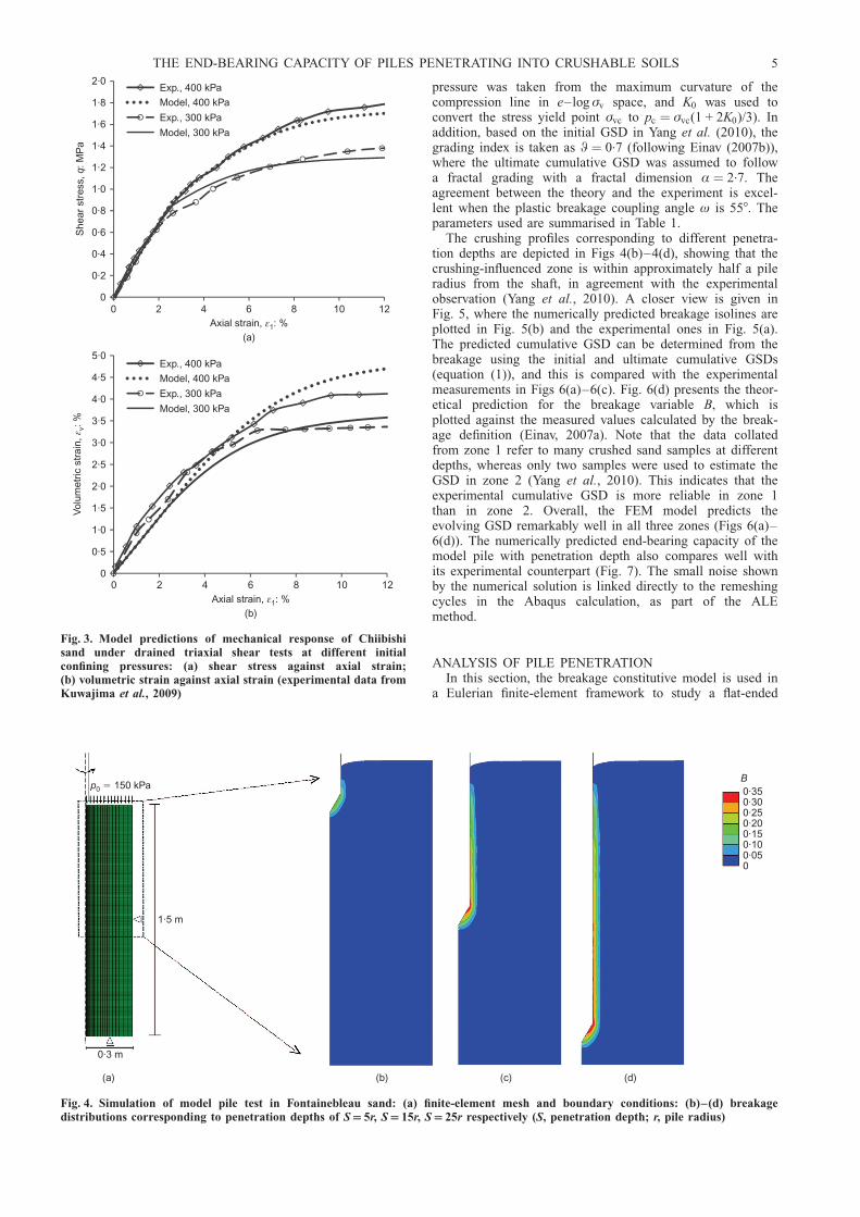
The axis-symmetric finite-element model is depicted inFig. 4(a), including the boundary conditions, the overallmodel dimensions based on Yang et al. (2010), and the meshdiscretisation. The preparation of the finite-element sampleinvolves three stages that represent the experimental set-up:a first stage where gravity is applied gradually; a secondstage where a top pressure of 150 kPa is gradually appliedto the surface of the model; and a third and last stage wherethe pile is driven into the modelled sand using the ALEtechnique. It was found that at the end of the second stagenone of the material points in the finite-element model was
actually yielding, and the state was purely elastic and couldbe matched by an elastic K0 condition. Therefore it isactually possible to start the analysis directly from the thirdstage, and using K0 ¼ �=(1� �) (� being Poisson’s ratio) toestablish the horizontal stresses using the known verticaleffective stresses.
The current analysis is based on parameters from DeGennaro & Frank (2002): � ¼ 0.3, K ¼ 28.3 MPa andG ¼ 13.1 MPa for stresses of the order of 100 kPa (as in thecurrent analysis), based on a series of triaxial experimentson quartz Fontainebleau sand. As indicated above, the initialstresses at the beginning of the penetration analysis corres-pond to an elastic solution with lateral earth coefficientK0 ¼ 0.43 (corresponding to � ¼ 0.3). Furthermore, stillfollowing De Gennaro & Frank (2002) the friction coeffi-cient is taken as M ¼ 1.5 (based on an effective frictionangle of � ¼ 36.58). The predictions in this paper are basedon these parameters, and without any adjustment, a fact thathighlights the model’s capabilities.
Other parameters are from Yang et al. (2010): the soil–pile interface friction coefficient � ¼ tan(� p) was calculatedusing the measured interface friction angle �p ¼ 258, the(effective) unit weight of sand ª ¼ 16.3 kN/m3, and thecritical comminution pressure pc ¼ 23 MPa was taken from aone-dimensional compression test (where the initial yield
2015105
Exp., 400 kPaModel, 400 kPaExp., 200 kPaModel, 200 kPa
20151050
Axial strain, : %(b)
ε1
0
0·2
0·4
0·6
0·8
1·0
1·2
1·4
0
Exp., 400 kPaModel, 400 kPaExp., 200 kPaModel, 200 kPa
She
ar s
tres
s,
: MP
aq
Axial strain, : %(a)
ε1
0
2
4
6
8
10
12
Vol
umet
ric s
trai
n,: %
ε v
Fig. 2. Model predictions of mechanical response of Dog’s Baysand under drained triaxial shear tests at different initialconfining pressures: (a) shear stress against axial strain;(b) volumetric strain against axial strain (experimental data fromKuwajima et al., 2009)
4 ZHANG, NGUYEN AND EINAV
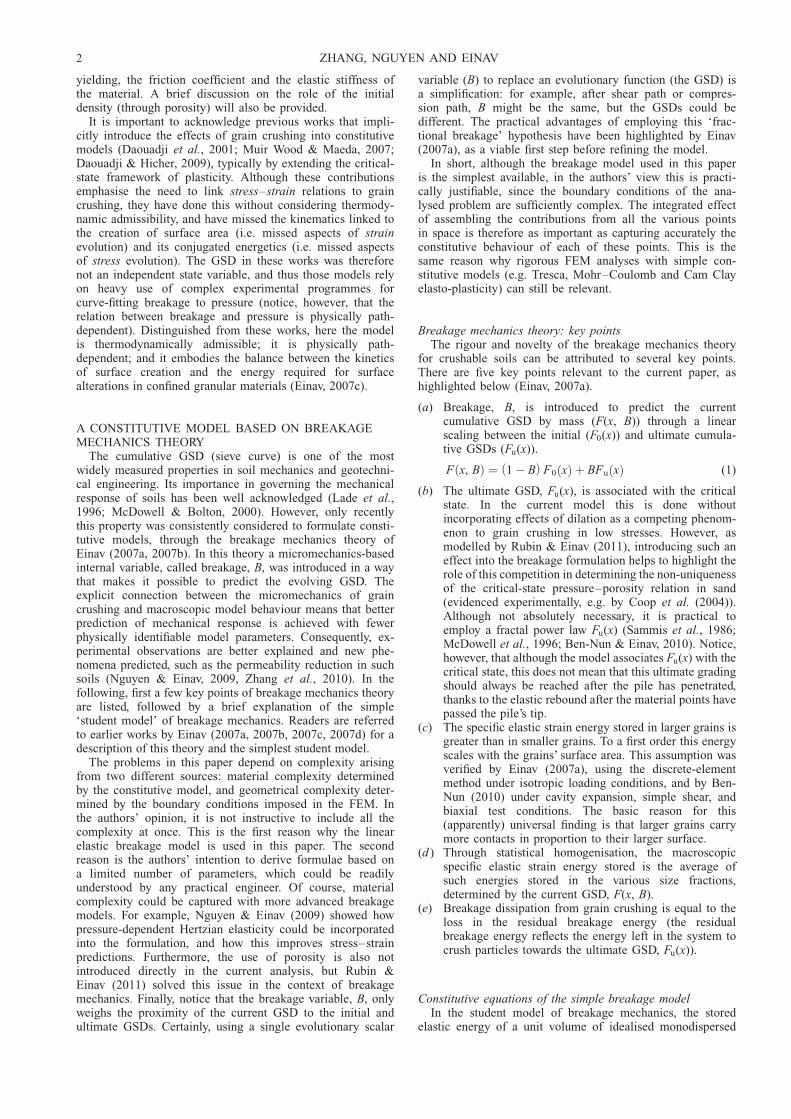
pressure was taken from the maximum curvature of thecompression line in e–log �v space, and K0 was used toconvert the stress yield point �vc to pc ¼ �vc(1 + 2K0)/3). Inaddition, based on the initial GSD in Yang et al. (2010), thegrading index is taken as W ¼ 0.7 (following Einav (2007b)),where the ultimate cumulative GSD was assumed to followa fractal grading with a fractal dimension Æ ¼ 2.7. Theagreement between the theory and the experiment is excel-lent when the plastic breakage coupling angle ø is 558. Theparameters used are summarised in Table 1.
The crushing profiles corresponding to different penetra-tion depths are depicted in Figs 4(b)–4(d), showing that thecrushing-influenced zone is within approximately half a pileradius from the shaft, in agreement with the experimentalobservation (Yang et al., 2010). A closer view is given inFig. 5, where the numerically predicted breakage isolines areplotted in Fig. 5(b) and the experimental ones in Fig. 5(a).The predicted cumulative GSD can be determined from thebreakage using the initial and ultimate cumulative GSDs(equation (1)), and this is compared with the experimentalmeasurements in Figs 6(a)–6(c). Fig. 6(d) presents the theor-etical prediction for the breakage variable B, which isplotted against the measured values calculated by the break-age definition (Einav, 2007a). Note that the data collatedfrom zone 1 refer to many crushed sand samples at differentdepths, whereas only two samples were used to estimate theGSD in zone 2 (Yang et al., 2010). This indicates that theexperimental cumulative GSD is more reliable in zone 1than in zone 2. Overall, the FEM model predicts theevolving GSD remarkably well in all three zones (Figs 6(a)–6(d)). The numerically predicted end-bearing capacity of themodel pile with penetration depth also compares well withits experimental counterpart (Fig. 7). The small noise shownby the numerical solution is linked directly to the remeshingcycles in the Abaqus calculation, as part of the ALEmethod.
ANALYSIS OF PILE PENETRATIONIn this section, the breakage constitutive model is used in
a Eulerian finite-element framework to study a flat-ended
12108642
121086420
Exp., 400 kPa
Model, 400 kPa
Exp., 300 kPa
Model, 300 kPa
Axial strain, : %(b)
ε1
0
0·2
0·4
0·6
0·8
1·0
1·2
1·4
1·6
1·8
2·0
0
Exp., 400 kPa
Model, 400 kPa
Exp., 300 kPa
Model, 300 kPa
She
ar s
tres
s,
: MP
aq
Axial strain, : %(a)
ε1
0
0·5
1·0
1·5
2·0
2·5
3·0
3·5
4·0
4·5
5·0
Vol
umet
ric s
trai
n,: %
ε v
Fig. 3. Model predictions of mechanical response of Chiibishisand under drained triaxial shear tests at different initialconfining pressures: (a) shear stress against axial strain;(b) volumetric strain against axial strain (experimental data fromKuwajima et al., 2009)
p0 150 kPa�
1·5 m
0·3 m
(a) (b) (c) (d)
B0·350·300·250·200·150·100·050
Fig. 4. Simulation of model pile test in Fontainebleau sand: (a) finite-element mesh and boundary conditions: (b)–(d) breakagedistributions corresponding to penetration depths of S 5r, S 15r, S 25r respectively (S, penetration depth; r, pile radius)
THE END-BEARING CAPACITY OF PILES PENETRATING INTO CRUSHABLE SOILS 5

cylindrical pile penetrating into a crushable sand, Chiibishisand (Kuwajima et al., 2009). This axis-symmetric FEMmodel is intended to overcome the large distortion issuesassociated with the ALE or updated Lagrangian method forpiles with high cone angles such as 908 in flat-tip piles(Sheng et al., 2005). An appropriate discretisation wasselected after a check was made to confirm that the resultsconverge upon mesh refinement (Zhang et al., 2010). Themodel and boundaries are illustrated in Fig. 8, in which only
part of the pile, with length L ¼ 4 m, is simulated. Asindicated in the figure, the lateral walls prevent horizontalmovements; the pile’s tip prevents vertical movement; andthe top and bottom walls maintain constant vertical stress�v0, and enable the inflow and outflow of mass fluxes at aconstant rate reflecting the pile’s penetration velocity. Thematerial properties are listed in Table 1 (based on thecalibration in the section ‘Model predictions’ above). Notethat the initial stresses are pre-established in current analyses
Axis ofsymmetry
Pile
�0–2 mm
�2–5 mm
�5–8 mm
Zone 1: high crushing
Zone 2: significant crushing
Zone 3: moderate crushing
B
0·350·300·250·200·150·100·050
(b)(a)
Fig. 5. Simulation of model pile test in Fontainebleau sand, profile of crushingzones: (a) experimental (reproduced from Yang et al., 2010); (b) numerical
10·10·01 10·10·010·001
Fin
er: %
Grain diameter: mm(b)
10·10·010·001
Fin
er: %
Grain diameter: mm(c)
Zone 3Zone 2
0
20
40
60
80
100
0·001
Fin
er: %
Grain diameter: mm(a)
Initial GSD
Ultimate GSD
Exp., zone 1Theory, zone 1
0
20
40
60
80
100Initial GSDUltimate GSDExp., zone 2Theory, zone 2
0
20
40
60
80
100 Initial GSDUltimate GSDExp., zone 3Theory, zone 3
0
0·05
0·10
0·15
0·20
0·25
Bre
aka
ge,B
(d)
Theory
Experiment
Zone 1
Fig. 6. Simulation of model pile test in Fontainebleau sand. Average grain size distributions for (a) zone 1, (b) zone 2,(c) zone 3; (d) average breakage index for zones 1, 2 and 3 indicated in Fig. 5(a)
6 ZHANG, NGUYEN AND EINAV

by applying designated external pressures. Although suchsands typically have lower unit weights, a unit weight ofª ¼ 20 kN/m3 was employed without much effect on theresults; this was confirmed by performing a separate sensi-tivity analysis (not shown). The diameter of the rigid pile isD ¼ 0.2 m; the shear stress at the interface is calculatedusing the Coulomb friction model with friction coefficient� ¼ tan(�/2) ¼ 0.4 (Durgunoglu & Mitchell, 1975).
Next, the experimental observations of the deformationpatterns given by Figs 9(a), 9(c) and 9(e) will be predicted
numerically using the model. This is achieved by employinga technique similar to the strain path method, which wasoriginally proposed by Baligh (1985) in terms of inviscidfluid streamlines and then by Einav & Randolph (2005)using the upper-bound theory of plasticity. Here, this tech-nique is adapted to employ the velocity profiles obtained bythe present numerical model, from the nodal velocities atsteady state corresponding to the fixed Eulerian FEM mesh,and corresponding to steady state. The steady state isnumerically determined after the penetration is sufficientlylarge such that the picture of breakage and plastic strainscease to evolve, with S/D of more than ten. The velocityfield at any point in the problem domain was calculated byemploying shape functions interpolating the nodal velocitiescorresponding to the numerical steady state. The positionsand trajectories of the material points were tracked fromtheir original positions. This procedure provides the numer-ical pictures of the soil deformation after the relevant S/Dpenetration has been attained, by tracking the steady-statestreamlines. Strictly speaking, the experimental pictures donot correspond to steady state. However, the use of thesteady-state velocity field from the Eulerian FEM seems tofacilitate excellent approximation to the deformation pat-terns, as proven by the agreement between the numericalsolutions (Figs 9(b), 9(d) and 9(f)) and the non-steadyexperimental deformation patterns (Figs 9(a), 9(c) and 9(e)).
In addition, the numerical model can be further assessedin the more traditional way, by comparing the numerical andexperimental tip resistances as the piles penetrate throughthe soil (Fig. 10). The agreement between these curves isvery good.
A NEW FORMULA FOR END-BEARING CAPACITYFACTOR
One way to express the end-bearing capacity of piles isoften written as
qp ¼ Nq� v0 (14)
where �v0 represents the initial vertical stress at a depthcorresponding to the pile tip, and Nq is the dimensionlessend-bearing capacity factor. More recently it has becomemore common to express the end-bearing capacity of pilesusing the initial effective confining pressure, p0, rather than�v0 (Vesic, 1973a, 1975; Al-Awquati, 1975), as
qp ¼ N�q p0 (15)
N�q ¼3
1þ 2K0
Nq (16)
where the modified end-bearing capacity factor N �q dependson Nq through the coefficient of lateral earth pressure at rest,K0: Both Nq and N�q are defined as functions of the frictionalangle at the critical state. Various equations have beenproposed in the past for these factors, and a few of thebetter-known ones are listed in Appendix 2.
For crushable soils, in addition to the effects of confiningpressure p0 on the bearing capacity (Fig. 10), it is reasonablyexpected that the critical comminution pressure pc will alsoplay an essential role in the bearing capacity equation. Theauthors’ numerical analysis (Fig. 11) shows the dependenceof N �q on both the confining and critical comminutionpressures, through a sort of overconsolidation ratio, p0/pc:According to this analysis N�q is expressed by a power lawof p0/pc, which can be represented by a straight line in alog–log plot such as that given in Fig. 11(b) to give therelation
2520151050
5
10
15
20
25
0
S r/
Theory
Experiment
qc: MPa
Fig. 7. Simulation of model pile test in Fontainebleau sand: end-bearing capacity qc against normalised penetration depth S/r
Outflow
4 m
8 m
Inflow
6 m
Fig. 8. Pile penetration in Chiibishi sand: axisymmetric Eulerianfinite-element models and boundary conditions, in which rigidpile is fixed, inflow material velocity is 0.01 m/s, and initial verticaland horizontal stresses are defined by nominating �v0 and �h0
THE END-BEARING CAPACITY OF PILES PENETRATING INTO CRUSHABLE SOILS 7

N�q ¼ Æpc
p0
� �2�
(17)
where Æ and � are parameters that will be found later todepend on the material stiffness (G and K) and the frictionparameter (M).
Since the power law relation in equation (17) is controlledby two parameters, Æ and �, it is necessary to quantify theirdependence on the fundamental model constants: the shearmodulus, G; the bulk modulus, K; the friction coefficient atcritical states, M; and the coupling angle, ø. Numericalresults for the variation of Æ and � with respect to penetra-tion depth (Table 2) shows that � apparently increases withthe penetration depth until steady state, while the change inÆ is not monotonic. A comparison has been made byconverting the experimental data from Kuwajima et al.(2009) into the definition of N�q: It is found that their
experimental Æ ranges from 17.96 to 33.66, and � from 0.28to 0.35 up to 3D penetration.
The results in Table 2 indicate that � reaches a constantvalue of 0.42 at steady state. This constant value can beconfirmed by a parametric study employing different valuesof G/K, M and ø. The numerical results are depicted in Fig.12, and the corresponding values of Æ and � are listed inTable 3. It can be seen that � ¼ 0.42 is independent of theother parameters. By contrast, Æ grows with increasing G/Kand M. Also, both Æ and � are independent of the couplingangle ø, and therefore the end-bearing capacity is alsoindependent of ø. Therefore Æ can be expressed as a func-tion of M and G/K only, the relationship of which isobtained from another series of simulations using differentvalues for G/K and M. The results obtained, listed in Table4, give the following relationship (with deviation errorsalways less than 4.5%)
(a) / 0·5, experimentS D �
(c) / 1, experimentS D � (d) / 1, theoryS D �
(e) / 3, experimentS D � (f) / 3, theoryS D �
(b) / 0·5, theoryS D �
Fig. 9. Pile penetration in Chiibishi sand: (a), (c), (e) experimental observation (Kuwajima et al., 2009; lines are coloured sand);(b), (d), (f) corresponding numerical predictions of soil deformation (S, penetration depth; D, pile diameter)
8 ZHANG, NGUYEN AND EINAV

Æ ¼ M3 þ 14G
K
� �(18)
Expressing G/K in terms of the Poisson’s ratio �, andusing the standard approximation M ¼ 6 sin�=(3� sin�),the complete expression for N �q can be given as
N �q ¼6 sin�
3� sin�
� �3
þ 73� 6�
1þ �
� �" #pc
p0
� �0:84
(19)
Next, note that, according to the breakage model, thecritical comminution pressure pc, which marks the onset ofisotropic yielding, depends on the GSD by way of W (seeequation (11)) according to
N �q ¼6 sin�
3� sin�
� �3
þ 73� 6�
1þ �
� �" #2KEc
Wp20
� �0:42
(20)
Therefore the last equation for the end-bearing capacity ofpiles penetrating into sand is here dependent on the confin-ing pressure p0, the GSD (via W), the critical breakageenergy Ec, the elastic Young’s modulus E and Poisson’s ratio�), and the friction angle �. The performance of this new
formula is compared in Fig. 13 for the two typical crushablesoils with four previous ones by Prandtl (1921), Terzaghi(1943) and Vesic (1973b, 1975). Both the Prandtl andTerzaghi solutions are pressure independent, unlike the ex-perimental results, which display high pressure sensitivity. Itappears that, of the earlier formulae, the two equations byVesic are the most successful in reproducing the pressuresensitivity, but either overestimate or underestimate the trueresult. On the other hand, the new formula appears highlysuccessful, both qualitatively and quantitatively. Note that,unlike the previous formulae, the new one depends on thecritical comminution pressure pc (a value that was thereforeemployed identically to make the pressure non-dimensionalin all the solutions). This critical comminution pressuredepends on the GSD, which for the first time truly underpinsthe compressibility of crushable soils.
The influence of the initial GSDs on N�q is furtherexplored in Fig. 14, based on the parameters for Dog’s Baysand (see Table 1), where the initial GSD is a power law, asindicated in the insert plot in this figure. The initial GSD isrepresented by the power law coefficient � (instead of Æ inequation (13)). It is evident that the end-bearing capacityincreases as the level of grain-size polydispersity increases.
0
0·5
1·0
1·5
2·0
2·5
3·0
0
(a)
Theory
Experiment
σv0 400 kPa�
σh0 200� kPa
S D/
qp: MPa
(b)
Theory
Experiment
(c)
Theory
Experiment
(d)
Theory
Experiment
222018161412108642 2220181614121086420
0·5
1·0
1·5
2·0
2·5
3·0
0
σv0 300� kPa
σh0 300� kPa
S D/
qp: MPa
0
0·5
1·0
1·5
2·0
2·5
3·0
0
σv0 200� kPa
σh0 100� kPa
S D/
qp: MPa
222018161412108642 2220181614121086420
0·5
1·0
1·5
2·0
2·5
3·0
0
σv0 100� kPa
σh0 100� kPa
S D/
qp: MPa
Fig. 10. Pile penetration in Chiibishi sand (Dr 90%): experimental measurement (Kuwajima et al., 2009) and numericalprediction of end-bearing capacity for different initial stress conditions (S, penetration depth; D, pile diameter)
THE END-BEARING CAPACITY OF PILES PENETRATING INTO CRUSHABLE SOILS 9

Finally, the effect of initial porosity, n0, could be taken intoaccount indirectly by considering the approximation in equa-tion (12). Accordingly, the end-bearing capacity factor isfound to depend on the initial porosity throughN�q / (1� n0)0:84: This means that denser sands should havehigher end-bearing capacity, in agreement with experimentalfindings by Konrad (1998) and Klotz & Coop (2001). Amore consistent derivation could follow by carrying out anew set of FEM simulations with the more advanced con-stitutive breakage-porosity model of Rubin & Einav (2011).
CONCLUSIONThe end-bearing capacity of piles penetrating into crush-
able soils is analysed within the context of breakage mech-anics theory. The paper has highlighted the importance of
N* q
S D2�
0·80·60·40·2
S D3�
10·1
log ( / )(b)p p0 c
0
20
40
60
80
100
120
140
160
180
200
220
240
0p p0 c/(a)
S D�
Steady state
S D3�
10
100
1000
0·01
S D2�
log
*N
q
S D�
Steady state
Fig. 11. Modified end-bearing capacity factor N�q against: (a) p0/pc
(solid symbols, K0 0.5; open symbols, K0 1.0); (b) log(p0/pc)(solid lines represent fitting curves; S, penetration depth; D, pilediameter; model parameters listed in Table 1)
Table 2. Effects of penetration depth on Æ and �
Penetration Æ � R2
S ¼ D 15.06 0.31 0.9975S ¼ 2D 18.25 0.35 0.9922S ¼ 3D 18.10 0.38 0.9960Steady 17.41 0.42 0.9995
1
log
*N
q
G K/ 0·75�
G K/ 1·0�
1
log
*N
q
log ( / )(b)p p0 c
M 1·6�
M 1·8�
1
log
*N
q
log ( / )(c)p p0 c
ω 0°�
ω 30°�
ω 60°�
10
100
0·1log ( / )
(a)p p0 c
G K/ 0·5�
10
100
0·1
M 1·4�
10
100
0·1
Fig. 12. Modified end-bearing capacity factor N�q against log(p0/pc)at steady-state penetration, K0 1: (a) effects of G/K; (b) effects ofM; (c) effects of ø (other model parameters, if not varied, are listedin Table 1)
10 ZHANG, NGUYEN AND EINAV

resorting to fundamental failure mechanisms for crushablesoils in determining the end-bearing capacity. Breakagemechanics theory does not only improve understanding ofthe constitutive response of crushable soils, but also providesan insight into problems such as the bearing capacity, andconsequently results in predictions that are free from empiri-cal parameters. This is particularly important for practicalpurposes, given the reliability issues in interpreting andincorporating data from both laboratory and field tests in theprediction of bearing capacity. The proposed end-bearingcapacity equation captures the effects of material crushabil-ity, in terms of the initial GSD, the confining pressure, the
Table 3. Effects of G/K, M, and ø on Æ and � for steady-statepenetration
Parameter Value Æ � R2
G/K 0.5 12.98 0.42 0.9990.75 16.98 0.42 0.9981.0 20.55 0.42 0.998
M 1.4 14.12 0.42 0.9961.6 15.68 0.42 0.9991.8 17.99 0.42 0.998
ø: degrees 0 17.18 0.42 0.9993060
Table 4. Effects of G/K and M on Æ (for � 0.42)
M ¼ 1.4 M ¼ 1.6 M ¼ 1.8
G/K ¼ 0.5 10.10 10.97 12.65G/K ¼ 0.75 13.47 14.57 16.24G/K ¼ 1.0 16.03 17.45 20.04
N* q
0·350·300·250·200·150·100·05
Experiment (S � 3 )DTheory (steady state)Prandtl (1921)Terzaghi (1943)Vesic (1975)Vesic (1973b)
N* q
0·350·300·250·200·150·100·050p p0 c/(b)
φ 43°14·5 MPa0·18
��
�Gv
0
20
40
60
80
100
120
140
160
180
200
220
240
0
Experiment (S � 3 )DTheory (steady state)Prandtl (1921)Terzaghi (1943)Vesic (1975)Vesic (1973b)
p p0 c/(a)
φ 43°14·5 MPa0·18
��
�Gv
0
20
40
60
80
100
120
140
160
180
200
Fig. 13. Modified end-bearing capacity factor N�q against p0/pc
for: (a) Chiibishi sand; (b) Dog’s Bay sand (experimental datafrom Kuwajima et al., 2009)
N* q
3210�1�2
�
F u(
2·7)
α�
100010010
50
55
60
65
70
75
80
85
�3
Per
cent
fine
r (1
00%
)
D D/ m
F0 with3, 0·5, 1,
1·5, 2, 2·3, 2·5� � � �
α2·
7�
0
0·2
0·4
0·6
0·8
1·0
1
Fig. 14. Influence of initial grain size distributions (GSDs) on N�q for Dog’s Bay sand described bythe shape parameter �. Inset shows the corresponding GSDs, always with an ultimate GSD definedby Æ ¼ 2.7, and a minimum grain size always being Dm
THE END-BEARING CAPACITY OF PILES PENETRATING INTO CRUSHABLE SOILS 11

critical breakage energy, and the constants of elasticity. Theresult appears to provide a more reliable prediction ofcapacities compared with any of the previous equations. Thenew bearing capacity equation can benefit the future designof pile foundations in sand materials, and can be used as areference for engineering purposes.
ACKNOWLEDGEMENTSThis research was supported by the Australian Research
Council through the ARC Discovery Projects fundingscheme (project number DP0986876). The second authorwishes to thank the University of Sydney for supportthrough the postdoctoral fellowship scheme.
APPENDIX 1: FINITE-ELEMENT IMPLEMENTATIONThe implementation of the breakage constitutive model described
in the paper is briefly presented for numerical analyses using thefinite-element method (FEM). The tensorial form of the triaxialmodel is used. The triaxial stresses and strains are written in termsof the stress and strain invariants as
p ¼ �13� kk ; q ¼
ffiffiffiffiffiffiffiffiffiffi32sijsij
q; �v ¼ ��kk ; �s ¼
ffiffiffiffiffiffiffiffiffiffiffi23eijeij
q(21)
where �ij is the Kronecker delta
sij ¼ � ij �� kk
3�ij and eij ¼ �ij �
�kk
3�ij (22)
The elastic component of the constitutive equations (equations (3)and (4)) of the model can be rewritten in tensorial form as
� ij ¼ 1� WBð ÞDijkl�ekl (23)
with the yield function given as
y ¼ W2Ec
p2
Kþ q2
3G
� �1� B
1� WB
� �2
þ q
Mp
� �2
� 1 < 0 (24)
and flow rules
��pij ¼ �º � 2 1� Bð Þ2EB sin2 ø
pEc
�ij
3þ 3sij
M2p2
" #¼ �ºQij (25)
�B ¼ �º2 1� Bð Þ2 cos2 ø
Ec
¼ �ºR (26)
The aim is to calculate the stress increment ��ij, given the currentstate of the material point at X (Fig. 15) and the strain increment��ij obtained from the non-linear finite-element analysis. The casewhere yielding occurs is considered, indicated by ytrial . 0 at trialpoint Y. This trial stress point is obtained by assuming linear elasticbehaviour with secant stiffness (1� WB)Dijkl for the strain increment��ij, resulting in the trial stress increment �� trial
ij ¼ (1� WB)Dijkl��kl:Performing a Taylor expansion of the yield function (equation (24))at the trial point Y (Fig. 15), the following is obtained
y ¼ ytrial þ @y
@B�B þ @y
@p
@p
@� ij
þ @y
@q
@q
@� ij
� ��� ij (27)
Substituting the flow rules (equations (25) and (26)) and the stressincrement in the form
�� ij ¼ � 1� WBð ÞDijkl��pkl �
W� ij
1� WB�B (28)
into equation (27) results in (noting that the total strain incrementhas been used to obtain the trial point Y, and hence there is no totalstrain increment beyond this trial point)
y ¼ ytrial þ @y
@BR� @y
@p
@p
@� ij
þ @y
@q
@q
@� ij
� �
3 1� WBð ÞDijklQkl þW� ij
1� WBR
���º
(29)
where Qkl and R are defined in equations (25) and (26). It isimplicitly implied here that all variables and quantities in equation(29) are evaluated at trial point Y. Enforcing the yield condition atpoint Z, y ¼ yZ ¼ 0, the multiplier �º can be obtained in the form
�º ¼ �ytrial@y
@BR � @y
@p
@p
@� ij
þ @y
@q
@q
@� ij
� �
3 1� WBð ÞDijklQkl þW� ij
1� WBR
��(30)
The stress increment ��YZij then follows as
��YZij ¼ � 1� WBð ÞDijklQkl þ
W� ij
1� WBR
��º (31)
The total stress increment ��ij is obtained as the sum of �� trialij
and ��YZij (Fig. 15),
�� ij ¼ �� trialij þ ��YZ
ij (32)
The above algorithm has been implemented in the commercial finite-element package Abaqus (2007) in the form of a VUMATsubroutine.
APPENDIX 2: PREVIOUS END-BEARING CAPACITYFACTORS
Prandtl (1921) proposed an end-bearing capacity factor for flatstrip surfaces punching through idealised weightless incompressiblemedia with assumed general shear failure
Nq ¼ tan2
4þ �
2
� �e tan� (33)
The assumption of general shear failure, however, is known to beproblematic for compressible soils. In such cases, the shear failuretends to be more local.
Terzaghi (1943) suggested modifying the equation above byincorporating the reduced friction angle �r ¼ tan�1 (2
3tan�) to
account for the local shear in compressible soils
Nq ¼ tan2
4þ �r
2
� �e tan�r (34)
Both equation (33) and equation (34) could be corrected in the usualway to allow these factors to be applied to the circular flat surfaceshape of typical piles. However, these equations still do not accountfor the increase of soil strength with depth. Moreover, equation (34)is known to give overly conservative answers for piles (Vesic,1973b).
Vesic (1973b) first attempted to modify Prandtl’s equation (33), byconsidering the soil compressibility. For that reason Vesic introducedthe reduction compressibility factor qc (here specified for the caseof a flat circular surface)
Nqc ¼ Nqqc (35)
qc ¼ exp 3:07 sin�ð Þ log 2I rð Þ1þ sin�
� 3:8 tan�
�(36)
where for sand the rigidity index I r ¼ G=(� v0 tan�) was introducedto capture the influence of the initial (effective) vertical stress �v0:
Vesic (1975) proposed another equation, an alternative to his ownequations (35) and (36), specified in terms of N�q as
y yYtrial 0� �
δσ YZij
δσ trialij
yX 0�yZ 0�
X
Y (trial point)
Z
�y 0: current yield surface
δσ ij
Fig. 15. Schematic diagram of the stress return algorithm
12 ZHANG, NGUYEN AND EINAV

N�q ¼ Nqcqc (37)
Nqc ¼ tan2
4þ �
2
� �e
2��ð Þ tan�
(38)
qc ¼3
3� sin�I rrð Þ
4 sin�3(1þsin�) (39)
The main conceptual change may be seen through the modifiedrigidity index I rr ¼ I r=(1þ ���vI r), which adds irreversible compres-sibility effects by way of ���v, the average volumetric strain in theplastic zone. Unfortunately, volumetric strain is a reference-dependent measure that requires a lot of guesswork. More critically,it was recommended to take ���v ¼ 0 for soils that are initially at theirdensest state (e.g. corresponding to the experiments evaluated in thecurrent paper). Unfortunately, the notion of densest state in crushablesoils is ambiguous. This is because, in such soils, the maximum andminimum densities depend on the GSD, which by itself varies duringthe deformation.
The above four formulae are plotted in Fig. 13 against equation(20) for both the Chiibishi and Dog’s Bay sands. Note that theexperimental conditions provide K0 ¼ 1, and therefore Nq is the sameas N�q: Since Vesic’s formulae (equations (35)–(39)) include �v0
through the use of Ir, the corresponding curves are indeed pressure-dependent. In the authors’ equation, both the compressibility of thesoil and the initial GSD are shown through the critical comminutionpressure, pc: The initial GSD in the current experiments was fixed. Itis recommended that future experiments explore the effect of theinitial GSD on the end-bearing capacity, in a way that could beevaluated using the current formula (equation (20)).
NOTATIONB breakageD pile diameter
Dijkl elastic stiffnessDM maximum grain sizeDm minimum grain sizeDr relative densityEB breakage energyEc critical breakage energyeij deviatoric strain tensor
F(x, B) current cumulative grain size distribution (GSD) by massF0(x) initial cumulative GSD by massFu(x) final cumulative GSD by mass
G shear modulusIr rigidity indexIrr modified rigidity indexK bulk modulus
K0 lateral earth pressure coefficient at restM friction coefficient at critical stateNq end-bearing capacity factorN�q modified end-bearing capacity factorn0 initial porosityp mean stress
pc critical comminution pressurepf mean stress at critical statep0 initial mean stressq triaxial shear stress
qc end-bearing capacity of cone-ended pilesqf triaxial shear stress at critical stateqp end-bearing capacity of flat-ended piles
r pile radiusS penetration depth
sij deviatoric stress tensorx grain sizey yield functionÆ power law coefficient defining ultimate GSD� power law coefficient defining initial GSDª unit weight� increment�ij Kronecker delta
�ij, �eij strain and elastic strain tensors
�v, �s volumetric and triaxial shear strains���v average volumetric strainW grading index� friction coefficient of the soil–pile interface (¼ tan�p)
� Poisson’s ratio�h0 initial horizontal stress�ij stress tensor�v0 initial vertical stress� friction angle of soil�p friction angle of soil–pile interface� specific elastic strain energyø coupling angle
REFERENCESAbaqus (2007). ABAQUS/Explicit user’s manual, Version 6.7. Provi-
dence, RI, USA: Hibbitt, Karlsson & Sorensen.Alba, J. L. & Audibert, J. M. E. (1999). Pile design in calcareous
and carbonaceous granular materials. Proc. 2nd Int. Conf. Engngfor Calcareous Sediments, Bahrain, 29–43.
Al-Awquati, A. (1975). On problems of soil bearing capacity atdepth. PhD dissertation, Duke University, Durham, NC, USA.
Altuhafi, F. N. & Coop, M. R. (2011). Changes to particle charac-teristics associated with the compression of sands. Geotechnique61, No. 6, 459–471, http://dx.doi.org/10.1680/geot.9.P.114.
Baligh, M. M. (1985). Strain path method. J. Soil Mech. Found.Div. ASCE 111, No. 9, 1108–1136.
Ben-Nun, O. (2010). Confined comminution of granular materials:self-organisation, attractors and patterns. PhD thesis, Universityof Sydney, Australia.
Ben-Nun, O. & Einav, I. (2010). The role of self-organizationduring confined comminution of granular materials. Phil Trans.R. Soc. London A 368, No. 1910, 231–247.
Coop, M. R., Sorensen, K. K., Freitas, T. B. & Georgoutsos, G.(2004). Particle breakage during shearing of a carbonate sand.Geotechnique 54, No. 3, 157–163, http://dx.doi.org/10.1680/geot.2004.54.3.157.
Daouadji, A. & Hicher, P.-Y. (2009). An enhanced constitutivemodel for crushable granular materials. Int. J. Numer. Analyt.Methods Geomech. 34, No. 6, 555–580.
Daouadji, A., Hicher, P.-Y. & Rahma, A. (2001). An elastoplasticmodel for granular materials taking into account grain breakage.Eur. J. Mech. A Solids 20, No. 1, 113–137.
Das, A., Nguyen, G. D. & Einav, I. (2011). Compaction bands dueto grain crushing in porous rocks: a theoretical approach basedon breakage mechanics. J. Geophys. Res. Solid Earth 116,http://dx.doi.org/10.1029/2011JB008265.
Datta, M., Gulhati, S. K. & Rao, G. V. (1979). Crushing ofcalcareous sands during shear. Proc. 11th Ann. Offshore Technol.Conf., Houston, TX, 1459–1467.
Datta, M., Gulhati, S. K. & Rao, G. V. (1980). An appraisal of theexisting practice of determining the axial capacity of deeppenetration piles in calcareous soils. Proc. 12th Ann. OffshoreTechnol. Conf., Houston, TX 4, 119–130.
De Gennaro, V. & Frank, R. (2002). Insight into the simulation ofcalibration chamber tests. Proc. 5th Eur. Conf. Numer. MethodsGeotech. Engng, Paris, 169–177.
Durgunoglu, H. T. & Mitchell, J. K. (1975). Static penetrationresistance of soils. I: Analysis. Proceedings of the conference onin situ measurement of soil properties, New York, pp. 151–171.
Einav, I. (2007a). Breakage mechanics. Part I: Theory. J. Mech.Phys. Solids 55, No. 6, 1274–1297.
Einav, I. (2007b). Breakage mechanics. Part II: Modelling granularmaterials. J. Mech. Phys. Solids 55, No. 6, 1298–1320.
Einav, I. (2007c). Fracture propagation in brittle granular matter.Proc. R. Soc. A 463, No. 2087, 3021–3035.
Einav, I. (2007d). Soil mechanics: breaking ground. Phil. Trans. R.Soc. London A, 365, No. 1861, 2985–3002.
Einav, I. & Randolph, M. F. (2005). Combining upper bound andstrain path methods for evaluating penetration resistance. Int. J.Numer. Methods Engng 63, No. 14, 1991–2016.
Foray, P., Nauroy, J.-F. & Colliat, J.-L. (1999). Mechanisms govern-ing the behaviour of foundations in carbonate sands and designparameters from in situ tests. Proc. 2nd Int. Conf. Engng forCalcareous Sediments, Bahrain, 55–68.
Golightly, C. R. & Hyde, A. F. L. (1988). Some fundamentalproperties of carbonate sands. Proceedings of the internationalconference on calcareous sediments, Perth, Australia, Vol. 1, pp.69–78.
THE END-BEARING CAPACITY OF PILES PENETRATING INTO CRUSHABLE SOILS 13

Hardin, B. O. (1985). Crushing of soil particles. J. Geotech. Engng111, No. 10, 1177–1192.
Hardin, B. O. & Black, W. L. (1966). Sand stiffness under varioustriaxial stresses. J. Soil Mech. Found. Engng ASCE 92, No. 2,27–42.
Joer, H. A., Jewell, R. J. & Randolph, M. F. (1999). Conepenetrometer testing in calcareous sediments. Proc. 2nd Int.Conf. on Calcareous Sediments, Bahrain, 243–252.
Klotz, E. U. & Coop, M. R. (2001). An investigation of the effectof soil state on the capacity of driven piles in sands. Geotech-nique 51, No. 9, 733–751, http://dx.doi.org/10.1680/geot.2001.51.9.733.
Konrad, J.-M. (1998). Sand state from cone penetrometer tests: aframework considering grain crushing stress. Geotechnique 48,No. 2, 201–215, http://dx.doi.org/10.1680/geot.1998.48.2.201.
Kuwajima, K., Hyodo, M. & Hyde, A. F. L. (2009). Pile bearingcapacity factors and soil crushability. J. Geotech. Geoenviron.Engng 135, No. 7, 901–913.
Lade, P. V., Yamamuro, J. A. & Bopp, P. A. (1996). Significance ofparticle crushing in granular materials. J. Geotech. Engng 122,No. 4, 309–316.
McDowell, G. R. & Bolton, M. D. (2000). Effect of particle sizedistribution on pile tip resistance in calcareous sand in thegeotechnical centrifuge. Granular Matter 2, No. 4, 179–187.
McDowell, G. R., Bolton, M. D. & Robertson, D. (1996). Thefractal crushing of granular materials. J. Mech. Phys. Solids 44,No. 12, 2079–2101.
Muir Wood, D. & Maeda, K. (2007). Changing grading of soil:effect on critical states. Acta Geotech. 3, No. 1, 3–14.
Nguyen, G. D. & Einav, I. (2009). The energetics of cataclasisbased on breakage mechanics. Pure Appl. Geophys. 166, No.10–11, 1693–1724.
Poulos, H. G. (1989). The mechanics of calcareous sediments.John Jaeger Memorial Lecture. Aust. Geomech., Special edn,8–41.
Poulos, H. G. & Chua, E. W. (1985). Bearing capacity of founda-tions on calcareous sand. Proc. 11th Int. Conf. Soil Mech.Found. Engng, San Francisco, CA 3, 1619–1622.
Prandtl, L. (1921). Uber die eindrigungsfestigkeit plastischer baus-troffe and die festigkeit von schneiden. Z. Angew. Math. Mech.1, No. 1, 15–20.
Rubin, M. B. & Einav, I. (2011). A large deformation breakagemodel of granular materials including porosity and inelastic
distortional deformation rate. Int. J. Engng Sci. 49, No. 10,1151–1169.
Russell, A. R. & Khalili, N. (2002). Drained cavity expansion insands exhibiting particle crushing. Int. J. Numer. Analyt. Meth-ods Geomech. 26, No. 4, 323–340.
Sammis, C. G., Osborne, R. H., Anderson, J. L., Banerdt, M. &White, P. (1986). Self-similar cataclasis in the formation of faultgouge. Pure Appl. Geophys. 124, No. 1–2, 53–78.
Sheng, D., Eigenbrod, K. & Wriggers, P. (2005). Finite elementanalysis of pile installation using large-slip frictional contact.Comput. Geotech. 32, No. 1, 17–26.
Terzaghi, K. (1943). Theoretical soil mechanics. New York, NY,USA: Wiley.
Turcotte, D. L. (1986). Fractals and fragmentation. J. Geophys. Res.91, No. B2, 1921–1926.
Vesic, A. S. (1973a). On penetration resistance and bearing capacityof piles in sand. Proc. 8th Int. Conf. Soil Mech. Found. Engng,Moscow, 78–81.
Vesic, A. S. (1973b). Analysis of ultimate loads of shallow founda-tions. J. Soil Mech. Found. Div. ASCE 99, No. 1, 45–73.
Vesic, A. S. (1975). Principles of pile foundation design, Soilmechanics series No. 38. Durham, NC, USA: School of En-gineering, Duke University.
Viggiani, G. & Atkinson, J. H. (1995). Stiffness of fine-grainedsoils at very small strains. Geotechnique 45, No. 2, 249–265,http://dx.doi.org/10.1680/geot.1995.45.2.249.
Yamamoto, N., Randolph, M. F. & Einav, I. (2009). A numericalstudy of the effect of foundation size for a wide range of sands.J. Geotech. Geoenviron. Engng 135, No. 1, 37–45.
Yang, Z. X., Jardine, R. J., Zhu, B. T., Foray, P. & Tsuha, C. H. C.(2010). Sand grain crushing and interface shearing duringdisplacement pile installation in sand. Geotechnique 60, No. 6,469–482, http://dx.doi.org/10.1680/geot.2010.60.6.469.
Yasufuku, N. & Hyde, A. F. L. (1995). Pile end-bearing capacity incrushable sands. Geotechnique 45, No. 4, 663–676, http://dx.doi.org/10.1680/geot.1995.45.4.663.
Yu, H.-S. (2000). Cavity expansion methods in geomechanics.Dordrecht, the Netherlands: Kluwer Academic.
Zhang, C. S., Nguyen, G. D. & Einav, I. (2010). Steady statepermeability profiles surrounding penetrating piles in crushablegranular media. Proceedings of the international symposium ongeomechanics and geotechnics: from micro to macro, Shanghai,pp. 789–795.
14 ZHANG, NGUYEN AND EINAV