the evolution of army wearable computers - ieee...
TRANSCRIPT
30 PERVASIVEcomputing US Government Work Not Protected by US Copyright
W E A R A B L E C O M P U T I N G
The Evolution of ArmyWearable Computers
Wearable computers will soonbecome a reality on the battle-field for frontline troops, underthe US Army’s Land Warriorprogram. Here, we trace the
evolution of Army wearable computers, from the ini-tial concept and first prototype, through downsiz-ing and improvements, to future product directions.We focus on two major programs central to the
Army’s development of wearablecomputers: the Soldier IntegratedProtective Ensemble (SIPE) andthe Land Warrior system. As theLand Warrior program nearsfruition, the Army continues toadvance the state of the art forwearable battlefield computers.
Early beginnings: The Soldier’sComputer
The history of Army wearable computers has itsroots in 1989 with James Schoening, a research ana-lyst working at the US Army Communications Elec-tronics Command (CECOM), Research Develop-ment and Engineering Center (RDEC). (See the“Glossary” sidebar for terms used in this article.)Schoening envisioned a small wearable computer,integrated with a wireless link and helmet-mounteddisplay (HMD), that could help individual soldierson the frontline. Working with Matt Zieniewicz,Schoening transformed his idea into a system archi-tecture with targeted technologies, such as wireless
data transmission, image capture, integrated GlobalPositioning System (GPS) receivers, and menu-driven software.
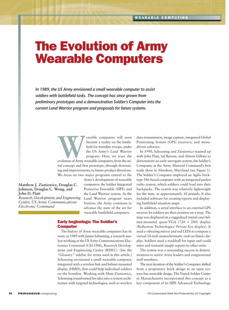
In 1990, Schoening and Zieniewicz teamed upwith John Flatt, Sal Barone, and Almon Gillette todemonstrate an early surrogate system, the Soldier’sComputer, at the Army Material Command’s firsttrade show in Aberdeen, Maryland (see Figure 1).The Soldier’s Computer employed an Agilis brick-type 386-based computer with an integrated packetradio system, which soldiers could load into theirbackpacks. The system was relatively lightweightfor the time, at approximately 10 pounds. It alsoincluded software for creating reports and display-ing battlefield situation maps.
In addition, a serial interface to an external GPSreceiver let soldiers see their position on a map. Themap was displayed on a ruggedized (metal case) hel-met-mounted quasi-VGA (720 × 280) display(Reflection Technologies’ Private Eye display). Itused a vibrating mirror and red LEDs to compose avirtual 14-inch monochromatic (red-on-black) dis-play. Soldiers used a trackball for input and couldenter and transmit simple reports to other units.
The system was a resounding success in demon-strations to senior Army leaders and congressionalstaff members.
The next iteration of the Soldier’s Computer shiftedfrom a proprietary brick design to an open sys-tem–bus wearable design. The Natick Soldier Centerin Massachusetts incorporated this concept as akey component of its SIPE Advanced-Technology
In 1989, the US Army envisioned a small wearable computer to assistsoldiers with battlefield tasks. The concept has since grown frompreliminary prototypes and a demonstration Soldier’s Computer into thecurrent Land Warrior program and proposals for future systems.
Matthew J. Zieniewicz, Douglas C.Johnson, Douglas C. Wong, andJohn D. FlattResearch, Development, and EngineeringCenter, US Army CommunicationsElectronic Command

Demonstration. The SIPE project, led byCarol Fitzgerald, was the first time the Armytreated the various combat equipment com-ponents for the individual soldier as oneintegrated system rather than as a con-glomeration of individual components(SIPE also included other advanced com-ponents in the areas of the fighting uniform,load-bearing equipment, weaponry, andthermal imaging).1
The prototype design for the SIPE pro-ject began in earnest in the spring of 1990.At that time, wearable computers were intheir infancy. Steve Mann at MIT had pro-duced some early wearable computers,2
and during the summer of 1991, CarnegieMellon University developed its VuManproject,3 but the SIPE computer approachdiffered from the typical research project.As part of a new digitized battlefield con-cept, it aimed to implement desired battle-field functions through technical meansrather than explore an advanced technol-ogy and then develop an application for it.This key difference influenced the entiredesign process.
The design team (see the “Soldier’s Com-puter Design Team” sidebar) had todevelop features (such as video capture)that could operate in a rugged environment.In simulated war-game exercises, actual sol-diers planned to test the system (10 proto-types) over several weeks in various out-door environments and during live-fireexercises. With this in mind from the out-set, the design team aimed to develop aportable, wearable battery-powered com-puter with suitable battlefield applicationssoftware. The computer needed to includeimage capture, an integrated radio fortransmitting data between soldiers, and a
portable display unit, preferably helmetmounted. The time frame for developingthe system was 24 months, with the lastthree months reserved for field testing anddemonstrations. The budget for the com-puter-radio-GPS portion (exclusive of thehelmet display unit) was US$500,000,including all labor, materials, softwaredevelopment, and prototype construction.
Functionality and requirementsBecause this was the Army’s first attempt
to bring computing devices to the individ-ual soldier, there were no preset systemrequirements, and users did not have spe-cific functions in mind. Initial brainstormingwith the Infantry School—led by the sys-tem’s software engineer, William Sanchez—developed key desired functions (listed inthe next paragraph). At the time, none ofthe functions were commercially availablein portable computers, but most were avail-able through various stand-alone electronicor computer components. The challengewas to integrate these piecemeal compo-nents into a lightweight package that could
OCTOBER–DECEMBER 2002 PERVASIVEcomputing 31
C4ISR Communications, command and control, computing, intelligence,
sensors, and reconnaissance
CECOM Communications Electronics Command
HMD Helmet-mounted display
IPT Integrated process teams
JCF AWE Joint Contingency Force Army Warfighting Experiment
MDSE Mission Data Support Equipment
ORD Operational Requirements Document
RDEC Research Development and Engineering Center
SIPE Soldier Integrated Protective Ensemble
TWS Thermal Weapon Sight
WSS Weapon subsystem
Glossary
Figure 1. The Soldier’s Computer at theArmy Material Command’s first trade showin 1990. Note the small helmet-mountedVGA display. The visible cord is the VGAfeed from the computer to the display. The military still uses this monocular concept in an improved form. (The smallstub antenna for the integrated spread-spectrum packet radio is not visible.)
N umerous engineers lent their support throughout the Sol-
dier’s Computer effort, but certain key personnel ensured
the success of developing the computer-radio-GPS system. The
core technical team members were Matt Zieniewicz, project
leader, system architect, and video capture and compression spe-
cialist; William Sanchez, chief applications development software
engineer; John Flatt, networking and communications engineer;
James Wright, project leader; Almon Gillette, packaging, electrical,
and mechanical interfaces; and Eric Hall, networking. In addition,
Carl Klatsky provided valuable assistance during the final prototype
construction and system checkout phase, and James Schoening
continued to work with the Infantry School on requirements; his
guidance and insight were essential throughout the project to
develop system concepts.
Soldier’s Computer Design Team
achieve the desired result without being toobulky and cumbersome or requiring toomuch power. The team decided early on toevaluate the best commercial componentsin each area (video capture, GPS, data com-munications, networking software, storagemedia, operating systems, programminglanguages, bus interfaces, and processorboards) and then make trade-offs to arriveat the best possible system architecture.They incorporated the functionally derivedhardware requirements in a custom hous-ing, developed within RDEC’s drafting,design, and fabrication division.
The new system aimed to digitize basicbattlefield operations to help soldiers
• Read maps, navigate, and maintain sit-uation awareness (so they could ask, forexample, “Where am I, where are mysquad members, and in which directionam I heading?”)
• Receive, prepare, and send written fieldreports (so they could, for example, senda call for fire or an operational order, orprepare spot reports or Frago orders—
written military reports used by front-line troops)
• Capture and transmit color still imagesfor reconnaissance purposes
• Access battlefield operations referencematerial (such as silhouettes of enemyfighting vehicles, first-aid procedures,common battlefield tasks, and standardprocedures)
These functions were the basis for thesoftware application, developed in C. Theteam developed other functions as separatemodules and included them in the mainprogram to provide modularity and ease oftesting. They also designed screens andscreen layouts from scratch, using inputfrom the Infantry School, the Army Human
Engineering Laboratory, and Natick engi-neers and project leaders. Fortunately, theinitial software’s functionality proved veryuseful, and in fact, the Army later used it asthe basis for the Land Warrior productionsystems.
System architectureTo satisfy the functionality required for
the Soldier’s Computer and its electronicssubsystem, the system team included thefollowing key hardware components: acomputer processor with memory, a GPSreceiver, a data radio, a video capture sys-tem, a digital compass, a miniature colorcamera, a video controller subsystem, anHMD, a power supply subsystem, wiringharnesses, and packaging (for more infor-mation, see the “Hardware for the Soldier’sComputer” sidebar). From a software per-spective, it was decided that it was best tocreate one main application program thatcould launch all the required functionsthrough subprograms (see the “Softwarefor the Soldier’s Computer” sidebar). Onthe basis of this design approach, the pro-
ject leader divided the software develop-ment into task areas and assigned them toappropriate specific project personnel.
The team then embarked on designingthe first custom Army wearable computerto be demonstrated under field conditions.In effect, the team became a custom PCclone manufacturer with a limited pro-duction run. They carefully designed thesystem by leveraging and integrating thelatest hardware components and technol-ogy available and incorporating the bestsoftware practices, programming lan-guages, and networking techniques.
Networking configurationThe individual Soldier Computers sent
the soldiers’ current positions in one-
minute intervals, along with digital reportsand captured still images, to a central gate-way unit over an FM packet radio with arange of up to one mile. At this fixed-gate-way base station, messages were relayed(between two fixed, not mobile, stations)to the Novell server over a wireless linkusing a wireless LAN card. The soldiersused the FM radio because it offered anincreased range over a wireless LAN sys-tem, and the packet mode better compen-sated for intermittent connectivity. (LANsdid not operate well under intermittentconditions at that time, owing to the net-working technology’s limitations.) Duringa data transmission, messages were relayedfrom the individual Soldier’s Computer tothe gateway unit, to the server, and thenback to the gateway for transmission to theappropriate Soldier’s Computer. Despitethe apparent multihop lag, soldiers did notnotice any degradation in service or timedelay.
Feedback from soldiersIn the fall of 1992, the Soldier’s Com-
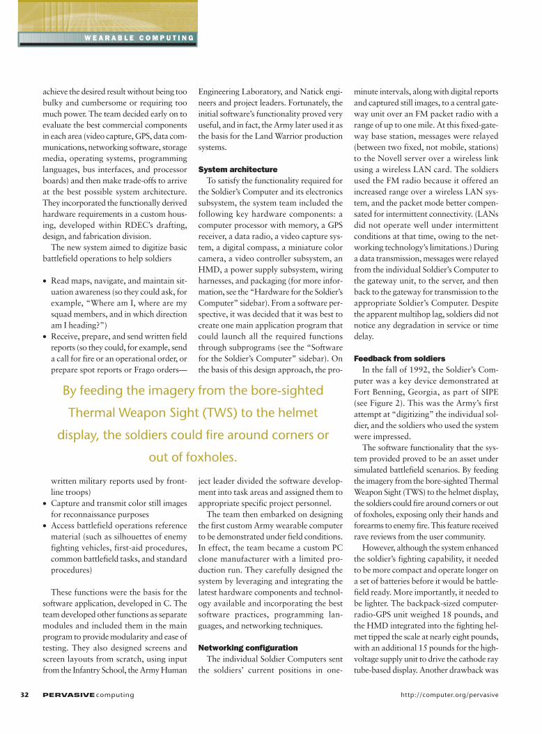
puter was a key device demonstrated atFort Benning, Georgia, as part of SIPE(see Figure 2). This was the Army’s firstattempt at “digitizing” the individual sol-dier, and the soldiers who used the systemwere impressed.
The software functionality that the sys-tem provided proved to be an asset undersimulated battlefield scenarios. By feedingthe imagery from the bore-sighted ThermalWeapon Sight (TWS) to the helmet display,the soldiers could fire around corners or outof foxholes, exposing only their hands andforearms to enemy fire. This feature receivedrave reviews from the user community.
However, although the system enhancedthe soldier’s fighting capability, it neededto be more compact and operate longer ona set of batteries before it would be battle-field ready. More importantly, it needed tobe lighter. The backpack-sized computer-radio-GPS unit weighed 18 pounds, andthe HMD integrated into the fighting hel-met tipped the scale at nearly eight pounds,with an additional 15 pounds for the high-voltage supply unit to drive the cathode raytube-based display. Another drawback was
32 PERVASIVEcomputing http://computer.org/pervasive
W E A R A B L E C O M P U T I N G
By feeding the imagery from the bore-sighted
Thermal Weapon Sight (TWS) to the helmet
display, the soldiers could fire around corners or
out of foxholes.
the delay in capturing and sending a stillvideo image. Owing to the limited pro-cessing speeds on the video capture boardand communications channel capacity
(9,600 bps), capturing and transmittingimages could take 45 to 75 seconds, duringwhich time soldiers couldn’t use the sys-tem for other operations.
The next phaseThe Natick Soldier Center completed its
SIPE project in two and a half years, and theArmy’s Chief of Staff was enthusiastic aboutfurthering efforts to field an integrated fight-ing system with a wearable computer-radio-GPS unit. The Army also continued explor-ing digitized components for the individualsoldier under various programs. For exam-ple, the Twenty-First Century Land Warriorproject examined advanced computing andelectronic products and concepts. Also, the
Figure 2. Testing and aligning the SIPEhelmet display with the Soldier’sComputer in July 1992. The visor reducedambient light and was a flip-up, flip-down display. It also provided ballisticand laser protection. The right-mountedsensor on the helmet’s top was an imageintensifier for night vision capabilities.The large brown case is the computer-radio-GPS unit.
Don’t runthe risk!
Be secure.
Order yourcharter
subscriptiontoday.
• Wireless Security
• Securing the Enterprise
• Designing for Security
• Infrastructure Security
• Privacy Issues
• Legal Issues
• Cybercrime
• Digital Rights Management
• Intellectual PropertyProtection and Piracy
• The Security Profession
• Education
IEEE Security & PrivacyEnsure that your networks operate safely and provide critical services even
in the face of attacks. Develop lasting security solutions, with this new
peer-reviewed publication. Top security professionals in the field share
information you can rely on:
h t t p : / / c o m p u t e r. o r g / s e c u r i t y
National Training Center-94 Soldier Systemas well as Task Force XXI were large wargame exercises conducted in the mid 1990s,in which frontline soldiers used a ruggedizedportable computer in field exercises at FortIrwin, California, to effect command andcontrol operations.
The Army’s main focus, however, wason producing an integrated fighting sys-tem. In 1993, it held a kick-off meeting toinitiate the development of Land Warrior,
a weapon system that, amongst manythings, could identify a soldier’s location,his or her fellow troops, and the enemy.First and foremost, the system aimed toenhance a soldier’s ability to move, shoot,communicate, and survive in modern war-fare. To achieve this, the Land WarriorSystem relied on communications, com-mand and control, computing, intelli-gence, sensor, and reconnaissance (C4ISR)technologies.
The Army leadership liked the SIPE sys-tem’s capabilities, so they incorporatedmany of its functions into Land Warrior.However, they also added new functionsand tried to achieve a lighter, smaller, lower-powered, and more rugged system. Likeany successful wearable computer or com-puting system, Land Warrior had to be easyto use, weigh almost nothing, work all day,and be comfortably placed and conve-niently located.
34 PERVASIVEcomputing http://computer.org/pervasive
W E A R A B L E C O M P U T I N G
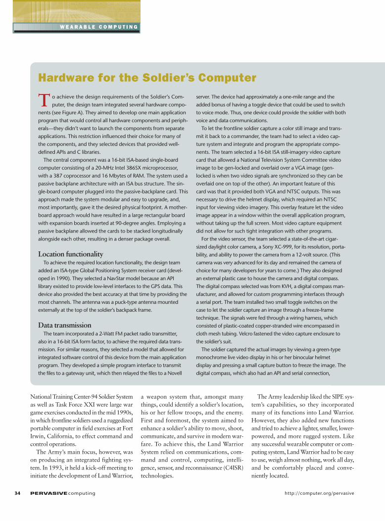
T o achieve the design requirements of the Soldier’s Com-
puter, the design team integrated several hardware compo-
nents (see Figure A). They aimed to develop one main application
program that would control all hardware components and periph-
erals—they didn’t want to launch the components from separate
applications. This restriction influenced their choice for many of
the components, and they selected devices that provided well-
defined APIs and C libraries.
The central component was a 16-bit ISA-based single-board
computer consisting of a 20-MHz Intel 386SX microprocessor,
with a 387 coprocessor and 16 Mbytes of RAM. The system used a
passive backplane architecture with an ISA bus structure. The sin-
gle-board computer plugged into the passive-backplane card. This
approach made the system modular and easy to upgrade, and,
most importantly, gave it the desired physical footprint. A mother-
board approach would have resulted in a large rectangular board
with expansion boards inserted at 90-degree angles. Employing a
passive backplane allowed the cards to be stacked longitudinally
alongside each other, resulting in a denser package overall.
Location functionalityTo achieve the required location functionality, the design team
added an ISA-type Global Positioning System receiver card (devel-
oped in 1990). They selected a NavStar model because an API
library existed to provide low-level interfaces to the GPS data. This
device also provided the best accuracy at that time by providing the
most channels. The antenna was a puck-type antenna mounted
externally at the top of the soldier’s backpack frame.
Data transmissionThe team incorporated a 2-Watt FM packet radio transmitter,
also in a 16-bit ISA form factor, to achieve the required data trans-
mission. For similar reasons, they selected a model that allowed for
integrated software control of this device from the main application
program. They developed a simple program interface to transmit
the files to a gateway unit, which then relayed the files to a Novell
server. The device had approximately a one-mile range and the
added bonus of having a toggle device that could be used to switch
to voice mode. Thus, one device could provide the soldier with both
voice and data communications.
To let the frontline soldier capture a color still image and trans-
mit it back to a commander, the team had to select a video cap-
ture system and integrate and program the appropriate compo-
nents. The team selected a 16-bit ISA still-imagery video capture
card that allowed a National Television System Committee video
image to be gen-locked and overlaid over a VGA image (gen-
locked is when two video signals are synchronized so they can be
overlaid one on top of the other). An important feature of this
card was that it provided both VGA and NTSC outputs. This was
necessary to drive the helmet display, which required an NTSC
input for viewing video imagery. This overlay feature let the video
image appear in a window within the overall application program,
without taking up the full screen. Most video capture equipment
did not allow for such tight integration with other programs.
For the video sensor, the team selected a state-of-the-art cigar-
sized daylight color camera, a Sony XC-999, for its resolution, porta-
bility, and ability to power the camera from a 12-volt source. (This
camera was very advanced for its day and remained the camera of
choice for many developers for years to come.) They also designed
an external plastic case to house the camera and digital compass.
The digital compass selected was from KVH, a digital compass man-
ufacturer, and allowed for custom programming interfaces through
a serial port. The team installed two small toggle switches on the
case to let the soldier capture an image through a freeze-frame
technique. The signals were fed through a wiring harness, which
consisted of plastic-coated copper-stranded wire encompassed in
cloth mesh tubing. Velcro fastened the video capture enclosure to
the soldier’s suit.
The soldier captured the actual images by viewing a green-type
monochrome live video display in his or her binocular helmet
display and pressing a small capture button to freeze the image. The
digital compass, which also had an API and serial connection,
Hardware for the Soldier’s Computer
Developing system requirements In 1994, the Army began a formal
requirements process, quantifying battle-field functions and required operations ina performance-based document known asan Operational Requirements Document.An ORD defines a desired system’s func-tions, operational capabilities, and perfor-mance, quantifying many performanceparameters with both threshold and objec-tive values. Before a system can be fielded,
it must demonstrate threshold values ofkey performance parameters listed in anORD in contractor and development test-ing and operational testing.
For Land Warrior, the Infantry School atFort Benning, Georgia, provided the initialfighting doctrine as described in the ORD.The year-long process involved numerousmeetings with both users and technicalexperts, who reviewed, in detail, the require-ments’ feasibility and applicability. For the
next phase—material development—theTraining and Doctrine Command SystemManager for Soldier Systems at Fort Ben-ning (a government program managementoffice) presented the user requirements tothe program manager’s office, ProgramManager (PM) Soldier at Fort Belvoir, Vir-ginia. (The Infantry School still reviewschanges made to these requirements.)
After the Army documented the formalsystem requirements in the Land Warrior
OCTOBER–DECEMBER 2002 PERVASIVEcomputing 35
tracked the direction the camera was
aimed at the time of capture, as well as
the soldier’s direction of travel for navi-
gation purposes. The signals from both
the camera and compass were fed
through a cloth mesh tubing wiring
harness. LEMO (a manufacturer of vari-
ous specialty connectors) and military-
type circular connectors were used on
all external connections for strength
and reliability under harsh conditions.
InterfaceTo interface the VGA output from
the computer and capture system to
the monochrome binocular helmet-
worn display that S-Tron designed,
and to interface to a custom joystick controller, Dick Tuttle’s dis-
play team from the Electronics Technology and Devices Labora-
tory of the Army Research Laboratory designed a custom
input/output card. The synchronization signal had to be slightly
modified to display properly in the helmet. This card also multi-
plexed the video signals from the weapon-mounted thermal
weapon sight and the daylight color camera, directing the sig-
nals either to the video capture card or directly to the helmet.
The card also provided standard keystroke inputs from the cus-
tom joystick to the keyboard and mouse input ports on the sin-
gle-board computer.
StorageTo store the operating system, application program, captured
still images, and maps, the team installed a 3.5-inch form factor
40-Mbyte ruggedized hard disk along the case’s inside perime-
ter. It could withstand 10G operating and 100G nonoperating
shock values. It had an initial grounding problem early in the
testing that resulted in some hard disk crashes, but once that
was rectified with a ground strap, none of the 10 units had a
hard disk failure.
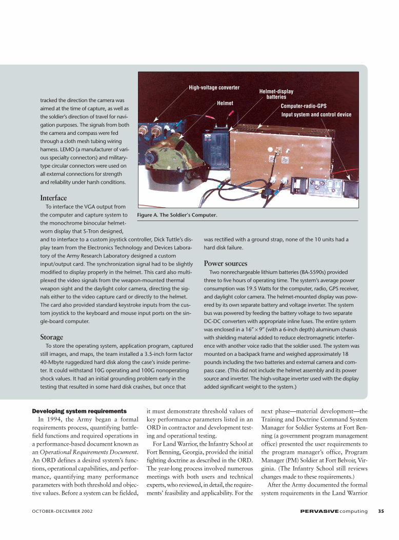
Power sourcesTwo nonrechargeable lithium batteries (BA-5590s) provided
three to five hours of operating time. The system’s average power
consumption was 19.5 Watts for the computer, radio, GPS receiver,
and daylight color camera. The helmet-mounted display was pow-
ered by its own separate battery and voltage inverter. The system
bus was powered by feeding the battery voltage to two separate
DC-DC converters with appropriate inline fuses. The entire system
was enclosed in a 16″ × 9″ (with a 6-inch depth) aluminum chassis
with shielding material added to reduce electromagnetic interfer-
ence with another voice radio that the soldier used. The system was
mounted on a backpack frame and weighed approximately 18
pounds including the two batteries and external camera and com-
pass case. (This did not include the helmet assembly and its power
source and inverter. The high-voltage inverter used with the display
added significant weight to the system.)
Figure A. The Soldier’s Computer.
Helmet-display batteries
Computer-radio-GPS
Input system and control device
High-voltage converter
Helmet
ORD, the program manager developed aperformance-based system specification,stating what the system should do but nothow it should do it (for example, the spec-ification might say “transmit reports” butnot “transmit reports using an FM-baseddigital radio”). For interoperability rea-sons, interface standards were specifiedbetween components and for external con-nections to other systems.
The PM Soldier Systems and Project Man-ager, Soldier Electronics offices, under theProgram Executive Office, Soldier, were pri-marily responsible for developing the LandWarrior system. They had to write the sys-tem performance specification and contractfor developing the system. An SPS translatesoperational requirements and other systemconstraints into system requirements and sys-tem architecture. The Army awarded theLand Warrior contract to a consortium ofcontractors, who worked with the govern-ment to allocate requirements to the sub-system level. The contractors performeddetailed design, build, integration, and testtasks to produce the system.
Key design factors A significant challenge facing Land War-
rior was keeping pace with current tech-nology and implementing a modularreplacement strategy to avoid maintaining
an obsolete system. The Army aimed toleverage mature and emerging technolo-gies, packaged for the warfighter’s envi-ronment, to field a supportable weaponsystem. However, while incorporating thelatest trends, the system still had to satisfyits ORD requirements and the constraintsof the Army’s Joint Technical Architecture.
In addition, the Land Warrior Inte-grated Process Teams (IPT) of governmentand contractor design engineers had tomake key design decisions on technicalstandards, approaches, and tools used tobuild the devices. Such decisions had tofacilitate an open, modular, and flexibletechnical architecture that suited the sol-diers and could operate in their environ-ment, including under water, at extremetemperatures, and under constant abuse.At the same time, the system had to min-imize audible, radio frequency, infrared,and visible emissions. So, the IPT had toask design trade-off questions such as,rotating disk or semiconductor (flash)memory? Infrared communications orBluetooth? AMLCD (Active Matrix Liq-uid Crystal Display), LOCS (Liquid Crys-tal On Silicon), or OLED (Organic LightEmitting Diode) display? Wireless, USB,or FireWire? PCMCIA or RS-232 inter-faces? Centralized power or numerousbatteries? Modular or integrated?
Furthermore, Land Warrior has beenincrementally built and tested using the rapidprototyping approach. Both the require-ments and specification evolved as the IPTlearned lessons throughout the developmentprocess. Early testing identified the prob-lems of obtaining adequate bandwidth andrange from the communication system,because Land Warrior requires transmittingvoice, data, and imagery within a squad.
In Fall 1999, the Land Warrior team ofgovernment and contractor engineersstarted working on the first rugged designof Land Warrior, Version 0.6. They aimedto present it at the Joint Contingency ForceArmy Warfighting Experiment (JCF AWE)in September 2000 (see Figure 3). This pre-liminary effort used commercial off-the-shelf and government-furnished compo-nents packaged to survive the soldier’senvironment.
The JCF AWESoldiers equipped with the Land Warrior,
Version 0.6 participated in three missionsduring the JCF AWE. The system provideda tremendous advantage to a platoon ofinfantrymen from the 82nd Airborne Divi-sion (Fort Bragg, N.C.) in this field testagainst the conventionally equipped oppos-ing force at the Joint Readiness TrainingCenter in Fort Polk, Louisiana.
36 PERVASIVEcomputing http://computer.org/pervasive
W E A R A B L E C O M P U T I N G
T he software system employed the legendary Disk Operating
System, with a custom package developed in C with a win-
dowing toolkit. This let the system emulate a Windows environment
and let the user select software buttons using a joystick interface
that emulated a mouse. The main menu navigation bar at the top of
the screen let the soldier select the different functions: mapping and
navigating, sending and receiving reports, using video mode (for
both capture and weapon firing), communicating, and accessing
reference material.
For mapping and navigation, soldiers could see both their own
location, provided by their GPS receiver, and that of their fellow
soldiers indicated as small icons on a scanned and registered map.
The reports section let platoon leaders send and receive several
basic battlefield reports. They could construct the reports through
a series of pull-down menus, requiring very little typing. They
could display a virtual keyboard to construct fragmentary or oper-
ational orders when necessary. The video mode let a soldier see a
video feed from either the Thermal Weapon Sight or the daylight
color camera in his or her monochrome (green on black) helmet
display. The soldier could then choose to capture one of these
images to send back to the base station. The system automatically
time- and date-stamped all images with the sending unit’s identity
and logged the images into a video database. However, it first
compressed the raw images into JPEG files, which could be trans-
mitted in approximately 30 seconds.
The reference material section consisted of several scanned images
of enemy fighting vehicles for field identification purposes along with
information about the weaponry characteristics. Also included were
common field manuals, evacuation procedures, first-aid information,
range card procedures, and prisoner of war procedures.
Software for the Soldier’s Computer
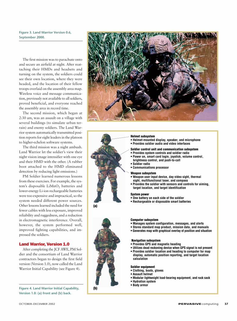
The first mission was to parachute ontoand secure an airfield at night. After reat-taching their HMDs and headsets andturning on the system, the soldiers couldsee their own location, where they wereheaded, and the location of their fellowtroops overlaid on the assembly area map.Wireless voice and message communica-tion, previously not available to all soldiers,proved beneficial, and everyone reachedthe assembly area in record time.
The second mission, which began at2:30 am, was an assault on a village withseveral buildings (to simulate urban ter-rain) and enemy soldiers. The Land War-rior system automatically transmitted posi-tion reports for eight leaders in the platoonto higher-echelon software systems.
The third mission was a night ambush.Land Warrior let the soldier’s view theirnight vision image intensifier with one eyeand their HMD with the other. (A rubberboot attached to the HMD eliminateddetection by reducing light emissions.)
PM Soldier learned numerous lessonsfrom these exercises. For example, the sys-tem’s disposable LiMnO2 batteries andlower-energy Li-ion rechargeable batterieswere too expensive and impractical, so thesystem needed different power sources.Other lessons learned included the need forfewer cables with less exposure, improvedreliability and ruggedness, and a reductionin electromagnetic interference. Overall,however, the system performed well,improved fighting capabilities, and im-pressed the soldiers.
Land Warrior, Version 1.0 After completing the JCF AWE, PM Sol-
dier and the consortium of Land Warriorcontractors began to design the first fieldversion (Version 1.0), now called the LandWarrior Initial Capability (see Figure 4).
OCTOBER–DECEMBER 2002 PERVASIVEcomputing 37
Figure 3. Land Warrior Version 0.6,September 2000.
(b)
Helmet subsystem• Helmet-mounted display, speaker, and microphone• Provides soldier audio and video interfaces
Soldier control unit and communication subsystem• Provides system controls and soldier radio• Power on, smart card login, joystick, volume control, brightness control, and push-to-call• Soldier radio• Communications processor
Weapon subsystem• Weapon user input device, day video sight, thermal sight, multifunctional laser, and compass• Provides the soldier with sensors and controls for aiming, target location, and target identification
Computer subsystem• Manages system configuration, messages, and alerts• Stores standard map product, mission data, and manuals• Generates map with graphical overlay of position and situation
Navigation subsystem• Provides GPS and magnetic heading• Utilizes dead reckoning device when GPS signal is not present• Provides soldier location and heading to computer for map display, automatic position reporting, and target location calculation
Soldier equipment• Clothing, boots, gloves• Assault helmet• Modular lightweight load-bearing equipment, and ruck sack• Hydration system• Body armor
(a)
System power• One battery on each side of the soldier• Rechargeable or disposable smart batteries
Figure 4. Land Warrior Initial Capability,Version 1.0: (a) front and (b) back.
Design rationaleThe IPTs incorporated the lessons learned
and addressed other fighting and opera-tional issues, leveraging commercial com-ponents, packaged and configured in a cus-tom fashion to meet battlefield conditionsand requirements.
To address the battery problems, the IPTdecided to use smart batteries that includedan SMBus 1.1 (System Management Bus,Version 1.1, a commercial standard) read-out of the battery’s charge status and otherdata. However, SMBus had to be convertedto USB, so a smart-battery adapter wasdeveloped. In addition, the IPT used novelpower management techniques to extendbattery life. Now, when the soldier flips uphis or her HMD, a switch turns off all videocomponents and places the computer instandby mode (voice communications andother functions still operate in this mode).
The integrated handheld display and key-board let platoon leaders view maps with alarger display (in addition to the HMD) andrapidly enter graphics and text for missionplanning. However, manufacturers are stilltrying to develop a color SVGA display (800× 600), six to nine inches diagonal, whichis the ideal size from a human-factors andform-factor standpoint. This display wouldallow for easy map reading while still fittingin a soldier’s Battlefield-Dress-Uniformcargo pocket. Furthermore, display manu-facturers are working to make a touch-screen display that is visible in all lightingconditions and meets all other environ-mental requirements, such as a wide rangeof operating temperatures.
Incorporating lessons learned from LandWarrior Version 0.6, which used a cen-tralized server, Land Warrior Version 1.0uses a more distributed software archi-tecture. Also, the Land Warrior systemdoes not contain enough storage forworldwide coverage of maps, and wire-less downloading of maps is problematicowing to bandwidth issues. PM Soldierthus developed a separate system, calledthe Mission Data Support Equipment, tohelp load mission data before a mission.The MDSE consists of a laptop computerand USB-to-Ethernet adapters. Its soft-ware includes the Mission Data package,which lets soldiers organize unit tasks andcreate situation maps, help files, operationorders, and mission overlays.
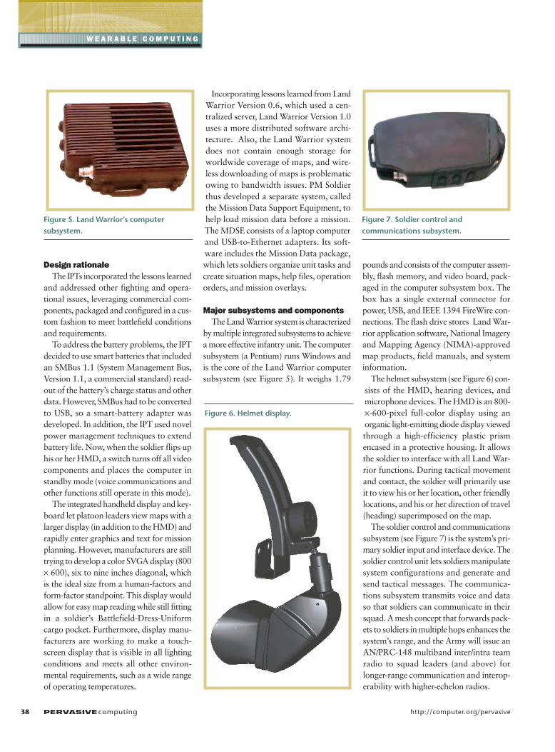
Major subsystems and componentsThe Land Warrior system is characterized
by multiple integrated subsystems to achievea more effective infantry unit. The computersubsystem (a Pentium) runs Windows andis the core of the Land Warrior computersubsystem (see Figure 5). It weighs 1.79
pounds and consists of the computer assem-bly, flash memory, and video board, pack-aged in the computer subsystem box. Thebox has a single external connector forpower, USB, and IEEE 1394 FireWire con-nections. The flash drive stores Land War-rior application software, National Imageryand Mapping Agency (NIMA)-approvedmap products, field manuals, and systeminformation.
The helmet subsystem (see Figure 6) con-sists of the HMD, hearing devices, andmicrophone devices. The HMD is an 800-×-600-pixel full-color display using anorganic light-emitting diode display viewedthrough a high-efficiency plastic prismencased in a protective housing. It allowsthe soldier to interface with all Land War-rior functions. During tactical movementand contact, the soldier will primarily useit to view his or her location, other friendlylocations, and his or her direction of travel(heading) superimposed on the map.
The soldier control and communicationssubsystem (see Figure 7) is the system’s pri-mary soldier input and interface device. Thesoldier control unit lets soldiers manipulatesystem configurations and generate andsend tactical messages. The communica-tions subsystem transmits voice and dataso that soldiers can communicate in theirsquad. A mesh concept that forwards pack-ets to soldiers in multiple hops enhances thesystem’s range, and the Army will issue anAN/PRC-148 multiband inter/intra teamradio to squad leaders (and above) forlonger-range communication and interop-erability with higher-echelon radios.
38 PERVASIVEcomputing http://computer.org/pervasive
W E A R A B L E C O M P U T I N G
Figure 5. Land Warrior’s computer subsystem.
Figure 6. Helmet display.
Figure 7. Soldier control and communications subsystem.
The weapons subsystem (WSS) has amounted Daylight Video Sight and TWSfor sighting. Depending on the duty posi-tion, the soldier can mount currentlyissued aiming lights, an infrared pointer,or a multifunctional laser. The laser com-bines multiple functions of currentlyfielded systems into one device and inte-grates a laser range finder and digital com-pass. A peg grip on the weapon’s stock hasbuttons that let soldiers make calls, tran-sition between sighting systems, captureimages, and locate targets without remov-ing a hand from the weapon. The WSSroutes all target information and imagecapture to the computer, which automat-ically determines target location and fillsmessage fields as applicable.
The navigation system integrates a GPSreceiver with an antenna on the left shoul-der, a magnetic compass heading sensor,and a dead reckoning module, whichextrapolates the last known position shouldthe GPS fail or receive insufficient signal. Italso graphically overlays the soldier’s posi-tion on a digital map, along with positions
of other Land Warrior systems, which areautomatically broadcast periodically.
The full Land Warrior system includesnot only the electronics but also all the otheritems that constitute the soldier’s combatload, including clothing, armor, weapons,and ammunition. Many integrated elementscomprise the Land Warrior fighting system,not just a computer—though it is a key com-ponent. For more information, see https://www.pmsoldiersystems.Army.mil/public/default.asp.
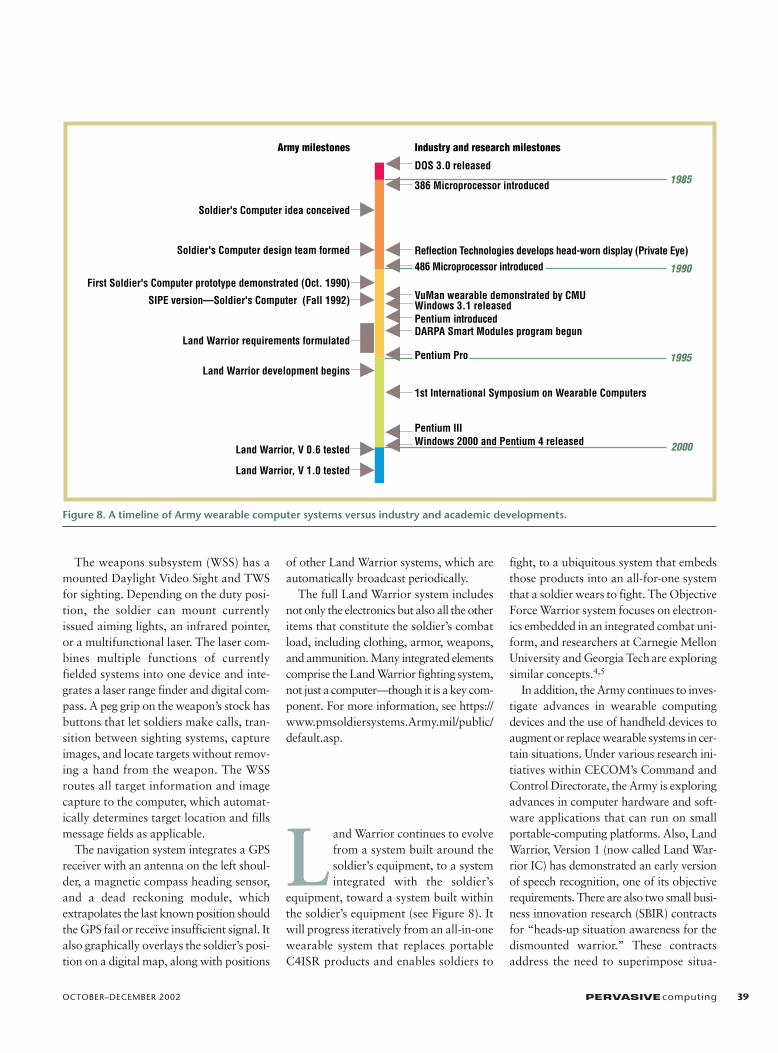
L and Warrior continues to evolvefrom a system built around thesoldier’s equipment, to a systemintegrated with the soldier’s
equipment, toward a system built withinthe soldier’s equipment (see Figure 8). Itwill progress iteratively from an all-in-onewearable system that replaces portableC4ISR products and enables soldiers to
fight, to a ubiquitous system that embedsthose products into an all-for-one systemthat a soldier wears to fight. The ObjectiveForce Warrior system focuses on electron-ics embedded in an integrated combat uni-form, and researchers at Carnegie MellonUniversity and Georgia Techare exploringsimilar concepts.4,5
In addition, the Army continues to inves-tigate advances in wearable computingdevices and the use of handheld devices toaugment or replace wearable systems in cer-tain situations. Under various research ini-tiatives within CECOM’s Command andControl Directorate, the Army is exploringadvances in computer hardware and soft-ware applications that can run on smallportable-computing platforms. Also, LandWarrior, Version 1 (now called Land War-rior IC) has demonstrated an early versionof speech recognition, one of its objectiverequirements. There are also two small busi-ness innovation research (SBIR) contractsfor “heads-up situation awareness for thedismounted warrior.” These contractsaddress the need to superimpose situa-
OCTOBER–DECEMBER 2002 PERVASIVEcomputing 39
Industry and research milestonesArmy milestones
1985
1990
DOS 3.0 released
386 Microprocessor introduced
1995
2000
Soldier's Computer idea conceived
Soldier's Computer design team formed
First Soldier's Computer prototype demonstrated (Oct. 1990)
SIPE version—Soldier's Computer (Fall 1992)
Land Warrior requirements formulated
Land Warrior development begins
Land Warrior, V 0.6 tested
Land Warrior, V 1.0 tested
Reflection Technologies develops head-worn display (Private Eye)486 Microprocessor introduced
Windows 3.1 releasedPentium introduced
Windows 2000 and Pentium 4 releasedPentium III
DARPA Smart Modules program begun
Pentium Pro
1st International Symposium on Wearable Computers
VuMan wearable demonstrated by CMU
Figure 8. A timeline of Army wearable computer systems versus industry and academic developments.
tional information on the HMD to helpavoid fratricide. Suomela and Lehikoinenpresented similar concepts for augmentedreality at ISWC 2000.6 Governmentresearch engineers are examining low-power computing devices, tablet PCs, andhandheld computing devices. As handhelddevices become more powerful, the needfor a wearable computer for certain appli-cations diminishes. Along these lines, thereis also an SBIR solicitation (request forbusiness contract proposals) calling for alocation-aware handheld computing devicewith integrated long-range (greater than500 km) communications. However, wear-able computers will always have a place ondismounted soldiers, who need both oftheir hands free to perform missions whilethe computer augments their capabilities.
In the applications area for mobile mil-itary computing platforms, four technolo-gies show particular promise:
• Intelligent agents on wireless wearablecomputers communicating with remoteservers
• Java-based collaboration tools withwhiteboarded military maps to plan andrehearse missions
• Speech recognition in the battlefield’shigh-noise and high-stress environments
• Mobile wireless database retrieval andsynchronization with handheld devices
Java and the Jini architecture show promisefor many portable networked applicationsthat support the network-centric battlefield.The Army is exploring Bluetooth and othercommunications technologies to reducecabling issues associated with wearablecomputing devices.
All these technologies will play a key rolein the Army’s vision of the future, as itsObjective Force Warrior system emergesover the next 10 years. Soon, the Army willhave soldiers with integrated battlefieldsystems consisting of the Land Warrior sys-tem. For now, the granddaddy of it all, thebackpack-sized Soldier’s Computer, willsoon become part of the Smithsonian’s per-manent collection, so you’ll be able to seeit on a future visit to the Washington D.C.area.
REFERENCES1. M. Nugent, “The Soldier Integrated
Protective Ensemble,” Army Research,Development, & Acquisition Bulletin,Sept./Oct. 1990, pp. 1–5.
2. S. Mann, “An Historical Account of the‘WearComp’ and ‘WearCam’ InventionsDeveloped for Applications in ‘PersonalImaging,’” IEEE Proc. 1st Int’l Symp.Wearable Computers, IEEE Press,Piscataway, N.J., 1997, pp. 66–73.
3. A. Samilagic et al., “Very RapidPrototyping of Wearable Computers: ACase Study of Custom versus Off-the-Shelf Design Methodologies,” Proc. 34thAnn. Design Automation Conf. (DAC2002), ACM Press, New York, 1997, pp.315–320.
4. D. Marculesa, R. Marculescu, and P.Khosla, “Challenges and Opportunities in
Electronic Textiles Modeling andOptimization,” Proc. 39th DesignAutomation Conf. 2002 (DAC 2002),AMC Press, New York, 2002, pp.175–180.
5. S. Park, K. Mackenzie, and S. Jayaraman,“The Wearable Motherboard: AFramework for Personalized MobileInformation Processing,” Proc. 39thConf. Design Automation (DAC 2002),ACM Press, New York, 2002, pp.170–174.
6. R. Suomela and J. Lehikoinen, “ContextCompass,” Proc. 4th Int’l Symp.Wearable Computers, IEEE CS Press, LosAlamitos, Calif., 2000, pp. 147–155.
For more information on this or any other comput-ing topic, please visit our Digital Library at http://computer.org/publications/dlib.
40 PERVASIVEcomputing http://computer.org/pervasive
W E A R A B L E C O M P U T I N G
the AUTHORS
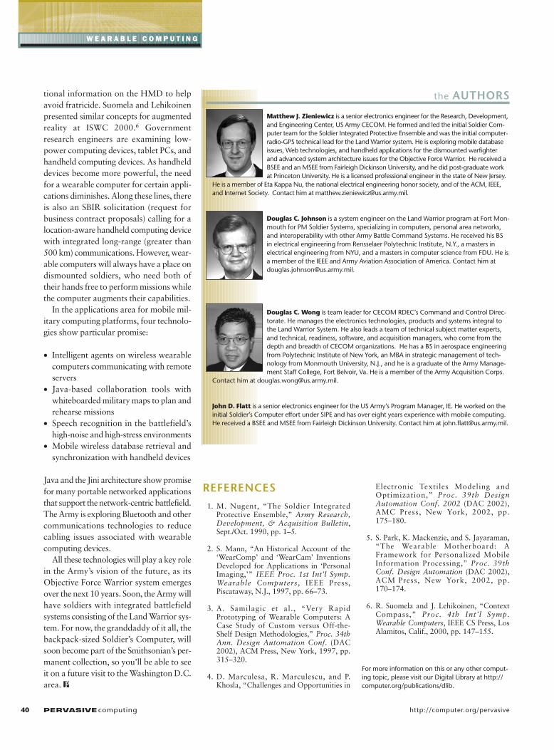
Matthew J. Zieniewicz is a senior electronics engineer for the Research, Development,and Engineering Center, US Army CECOM. He formed and led the initial Soldier Com-puter team for the Soldier Integrated Protective Ensemble and was the initial computer-radio-GPS technical lead for the Land Warrior system. He is exploring mobile databaseissues, Web technologies, and handheld applications for the dismounted warfighterand advanced system architecture issues for the Objective Force Warrior. He received aBSEE and an MSEE from Fairleigh Dickinson University, and he did post-graduate workat Princeton University. He is a licensed professional engineer in the state of New Jersey.
He is a member of Eta Kappa Nu, the national electrical engineering honor society, and of the ACM, IEEE,and Internet Society. Contact him at [email protected].
Douglas C. Johnson is a system engineer on the Land Warrior program at Fort Mon-mouth for PM Soldier Systems, specializing in computers, personal area networks,and interoperability with other Army Battle Command Systems. He received his BSin electrical engineering from Rensselaer Polytechnic Institute, N.Y., a masters inelectrical engineering from NYU, and a masters in computer science from FDU. He isa member of the IEEE and Army Aviation Association of America. Contact him [email protected].
Douglas C. Wong is team leader for CECOM RDEC’s Command and Control Direc-torate. He manages the electronics technologies, products and systems integral tothe Land Warrior System. He also leads a team of technical subject matter experts,and technical, readiness, software, and acquisition managers, who come from thedepth and breadth of CECOM organizations. He has a BS in aerospace engineeringfrom Polytechnic Institute of New York, an MBA in strategic management of tech-nology from Monmouth University, N.J., and he is a graduate of the Army Manage-ment Staff College, Fort Belvoir, Va. He is a member of the Army Acquisition Corps.
Contact him at [email protected].
John D. Flatt is a senior electronics engineer for the US Army’s Program Manager, IE. He worked on theinitial Soldier’s Computer effort under SIPE and has over eight years experience with mobile computing.He received a BSEE and MSEE from Fairleigh Dickinson University. Contact him at [email protected].