the evolution of product line assets - software engineering
TRANSCRIPT

The Evolution of Product Line Assets John D. McGregor
June 2003
TECHNICAL REPORT CMU/SEI-2003-TR-005 ESC-TR-2003-005


Pittsburgh, PA 15213-3890
The Evolution of Product Line Assets CMU/SEI-2003-TR-005 ESC-TR-2003-005 John D. McGregor
June 2003
Product Line Practice Initiative
Unlimited distribution subject to the copyright.

This report was prepared for the
SEI Joint Program Office HQ ESC/DIB 5 Eglin Street Hanscom AFB, MA 01731-2116
The ideas and findings in this report should not be construed as an official DoD position. It is published in the interest of scientific and technical information exchange.
FOR THE COMMANDER
Christos Scondras Chief of Programs, XPK
This work is sponsored by the U.S. Department of Defense. The Software Engineering Institute is a federally funded research and development center sponsored by the U.S. Department of Defense.
Copyright 2003 by Carnegie Mellon University.
NO WARRANTY
THIS CARNEGIE MELLON UNIVERSITY AND SOFTWARE ENGINEERING INSTITUTE MATERIAL IS FURNISHED ON AN "AS-IS" BASIS. CARNEGIE MELLON UNIVERSITY MAKES NO WARRANTIES OF ANY KIND, EITHER EXPRESSED OR IMPLIED, AS TO ANY MATTER INCLUDING, BUT NOT LIMITED TO, WARRANTY OF FITNESS FOR PURPOSE OR MERCHANTABILITY, EXCLUSIVITY, OR RESULTS OBTAINED FROM USE OF THE MATERIAL. CARNEGIE MELLON UNIVERSITY DOES NOT MAKE ANY WARRANTY OF ANY KIND WITH RESPECT TO FREEDOM FROM PATENT, TRADEMARK, OR COPYRIGHT INFRINGEMENT.
Use of any trademarks in this report is not intended in any way to infringe on the rights of the trademark holder.
Internal use. Permission to reproduce this document and to prepare derivative works from this document for internal use is granted, provided the copyright and "No Warranty" statements are included with all reproductions and derivative works.
External use. Requests for permission to reproduce this document or prepare derivative works of this document for external and commercial use should be addressed to the SEI Licensing Agent.
This work was created in the performance of Federal Government Contract Number F19628-00-C-0003 with Carnegie Mel-lon University for the operation of the Software Engineering Institute, a federally funded research and development center. The Government of the United States has a royalty-free government-purpose license to use, duplicate, or disclose the work, in whole or in part and in any manner, and to have or permit others to do so, for government purposes pursuant to the copy-right license under the clause at 252.227-7013.
For information about purchasing paper copies of SEI reports, please visit the publications portion of our Web site (http://www.sei.cmu.edu/publications/pubweb.html).

CMU/SEI-2003-TR-005 i
Table of Contents
Abstract..................................................................................................................vii
1 Introduction .....................................................................................................1
2 Background .....................................................................................................5 2.1 Software Product Lines .............................................................................5
2.2 External Forces for Change.......................................................................6
2.3 Internal Forces for Change........................................................................8 2.3.1 Core Asset Developers ..................................................................8 2.3.2 Product Developers .......................................................................8 2.3.3 Management..................................................................................8
2.4 Software Evolution.....................................................................................9
2.5 Evolution Mechanisms.............................................................................10 2.5.1 Properties of the Change Mechanism ..........................................11 2.5.2 Properties of the Change Itself.....................................................11 2.5.3 Properties of the System..............................................................12 2.5.4 Properties of the Change Process ...............................................12
3 Concepts of Product Line Evolution ............................................................15 3.1 Specifying the Direction of Evolution........................................................15
3.2 Influences on Evolution ...........................................................................16 3.2.1 Software Product Line Practice Areas..........................................17 3.2.2 Unanticipated Evolution ...............................................................17 3.2.3 Organizational Influences.............................................................18 3.2.4 Type of Personnel........................................................................18
3.3 Evolution Propagation .............................................................................18 3.3.1 The Product Line’s Scope ............................................................20 3.3.2 Software Architecture...................................................................20 3.3.3 Documents and Plans..................................................................21 3.3.4 Software Modules ........................................................................21
3.4 Risks of Evolution....................................................................................22
4 Implementing Evolution ................................................................................23 4.1 “Evolve Each Asset” Pattern ....................................................................23
ii CMU/SEI-2003-TR-005
4.2 Evolution Process ................................................................................... 25 4.2.1 Initiate Evolution .......................................................................... 25 4.2.2 Develop an Evolution Plan........................................................... 26 4.2.3 Apply Transformations................................................................. 26 4.2.4 Accept the Evolved Assets .......................................................... 26
4.3 Evolution Metrics..................................................................................... 27
4.4 Testing During Evolution ......................................................................... 27
4.5 Attached Process Definition .................................................................... 28
5 Support for Evolution ................................................................................... 29 5.1 Notation for Evolution.............................................................................. 29
5.2 Asset Development Techniques .............................................................. 30 5.2.1 Design for Evolution .................................................................... 30 5.2.2 Architecture/Design Patterns ....................................................... 31 5.2.3 Standard Life Cycles ................................................................... 32 5.2.4 Technology Forecasting .............................................................. 33
5.3 Evolution Transformations....................................................................... 33 5.3.1 Refactoring.................................................................................. 34 5.3.2 Reconfiguration ........................................................................... 34 5.3.3 Customization.............................................................................. 34 5.3.4 Model Transformations................................................................ 35 5.3.5 Change Impact Analysis .............................................................. 36 5.3.6 Incremental Consistency Analysis ............................................... 37
5.4 Automated Techniques............................................................................ 37 5.4.1 Change Management .................................................................. 38 5.4.2 Documentation ............................................................................ 41 5.4.3 Program Analysis Tools............................................................... 41
6 Summary ....................................................................................................... 43
Bibliography ...................................................................................................... 45

CMU/SEI-2003-TR-005 iii
List of Figures
Figure 1: Product Line Activities .............................................................................6
Figure 2: Porter’s Five Forces Model .....................................................................7
Figure 3: Evolutionary Life Cycle of a Product Line (Adapted from Svahnberg and Bosch’s Work [Svahnberg 99]) .......................................................19
Figure 4: “Evolve Asset” Pattern...........................................................................23
Figure 5: Evolutionary Ripple ...............................................................................25
Figure 6: Business Process Life Cycle .................................................................32
Figure 7: Inheritance ............................................................................................35
Figure 8: Wrapping...............................................................................................35
Figure 9: Dimensions of Change..........................................................................39
Figure 10: Implications of Evolution........................................................................40

iv CMU/SEI-2003-TR-005
CMU/SEI-2003-TR-005 v
List of Tables
Table 1: Anticipated Versus Unanticipated Evolution ..........................................17
Table 2: Propagation Paths.................................................................................20

vi CMU/SEI-2003-TR-005

CMU/SEI-2003-TR-005 vii
Abstract
Change is a natural, although not always welcome, part of product line development. The changes may be initiated to correct, improve, or extend assets or products. Since no asset is independent of all other assets, changes to one asset often require corresponding changes in other assets. And changes to assets propagate to affect all the products using those assets. Many of the practices of a successful product line initiate, manage, or consume these changes. Both conceptual techniques and software tools are available to assist in the man-agement of these changes.
The focus of this technical report is how evolutionary changes affect the various types of as-sets in a software product line. Change can be anticipated and managed, or it can be unantici-pated and potentially disruptive. This technical report defines a few basic evolution concepts and then discusses those product line practices that initiate, anticipate, control, and direct the evolution. Conceptual and automated techniques that support these practices are also pre-sented.

viii CMU/SEI-2003-TR-005

CMU/SEI-2003-TR-005 1
1 Introduction
Evolution is the accumulated effects of change over time. Forces drive the change in a certain direction at a certain point in time, and whether those forces are anticipated or controlled is uncertain. In addition, the direction of that change may or may not be desirable. For these reasons, evolution is a particular challenge for a product line organization. In a software product line, multiple products are developed from a common set of core assets. The complex relationships among those assets, and between those assets and the products they are part of, magnify the effects of evolution.
Product line assets change over time. In some cases, they change in response to a specific stimulus such as the need to meet a new standard or to address an emerging market niche. In other cases, assets are changed for reasons specific to the asset such as removing defects or achieving consistency with other assets. In the first case, the effects of the change can be an-ticipated and directed. In the second case, the effects may not be recognized until several changes have accumulated.
Asset evolution happens in response to forces both outside the product line organization and within it:
• A new release of a standard, which is integral to the products, forces changes in core as-sets and directs the evolution toward compliance with the standard. Normally, such a re-lease can be anticipated, its impact can be analyzed, and the resulting changes can be managed.
• Adopting new technologies forces assets to change. This may be part of a continuous evolution as a technology matures, or it may be radical change if a disruptive technology emerges and forces a major change in direction for several assets.
• A change in marketing strategy can be an internal evolutionary force that directs the evo-lution toward higher performance or more features.
2 CMU/SEI-2003-TR-005
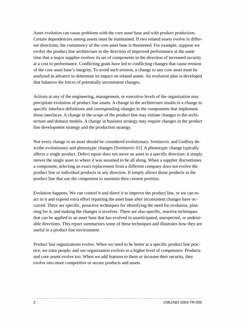
Asset evolution can cause problems with the core asset base and with product production. Certain dependencies among assets must be maintained. If two related assets evolve in differ-ent directions, the consistency of the core asset base is threatened. For example, suppose we evolve the product line architecture in the direction of improved performance at the same time that a major supplier evolves its set of components in the direction of increased security at a cost to performance. Conflicting goals have led to conflicting changes that cause erosion of the core asset base’s integrity. To avoid such erosion, a change to any core asset must be analyzed in advance to determine its impact on related assets. An evolution plan is developed that balances the forces of potentially inconsistent changes.
Actions at any of the engineering, management, or executive levels of the organization may precipitate evolution of product line assets. A change in the architecture results in a change to specific interface definitions and corresponding changes in the components that implement those interfaces. A change in the scope of the product line may initiate changes to the archi-tecture and domain models. A change in business strategy may require changes in the product line development strategy and the production strategy.
Not every change to an asset should be considered evolutionary. Svetinovic and Godfrey de-scribe evolutionary and phenotypic changes [Svetinovic 01]. A phenotypic change typically affects a single product. Defect repair does not move an asset in a specific direction; it simply moves the single asset to where it was assumed to be all along. When a supplier discontinues a component, selecting an exact replacement from a different company does not evolve the product line or individual products in any direction. It simply allows those products in the product line that use the component to maintain their current position.
Evolution happens. We can control it and direct it to improve the product line, or we can re-act to it and expend extra effort repairing the asset base after inconsistent changes have oc-curred. There are specific, proactive techniques for identifying the need for evolution, plan-ning for it, and making the changes it involves. There are also specific, reactive techniques that can be applied to an asset base that has evolved in unanticipated, unexpected, or undesir-able directions. This report summarizes some of these techniques and illustrates how they are useful in a product line environment.
Product line organizations evolve. When we need to be better at a specific product line prac-tice, we train people, and our organization evolves to a higher level of competence. Products and core assets evolve too. When we add features to them or increase their security, they evolve into more competitive or secure products and assets.

CMU/SEI-2003-TR-005 3
Evolution is a greater threat to the core asset base than to a typical reuse repository of loosely coupled or even totally independent artifacts. The core asset base of a software product line has a large number of interdependencies among assets and requires more effort to maintain consistency over time. This report focuses on the evolution of core assets but considers the effect of that evolution on the product line’s products and organization. We survey existing techniques and relate them to the practice areas defined in A Framework for Software Product Line PracticeSM developed by Clements and Northrop [Clements 02a, Clements 02c].
SM Architecture Tradeoff Analysis Method and ATAM are service marks of Carnegie Mellon Univer-
sity.

4 CMU/SEI-2003-TR-005
CMU/SEI-2003-TR-005 5
2 Background
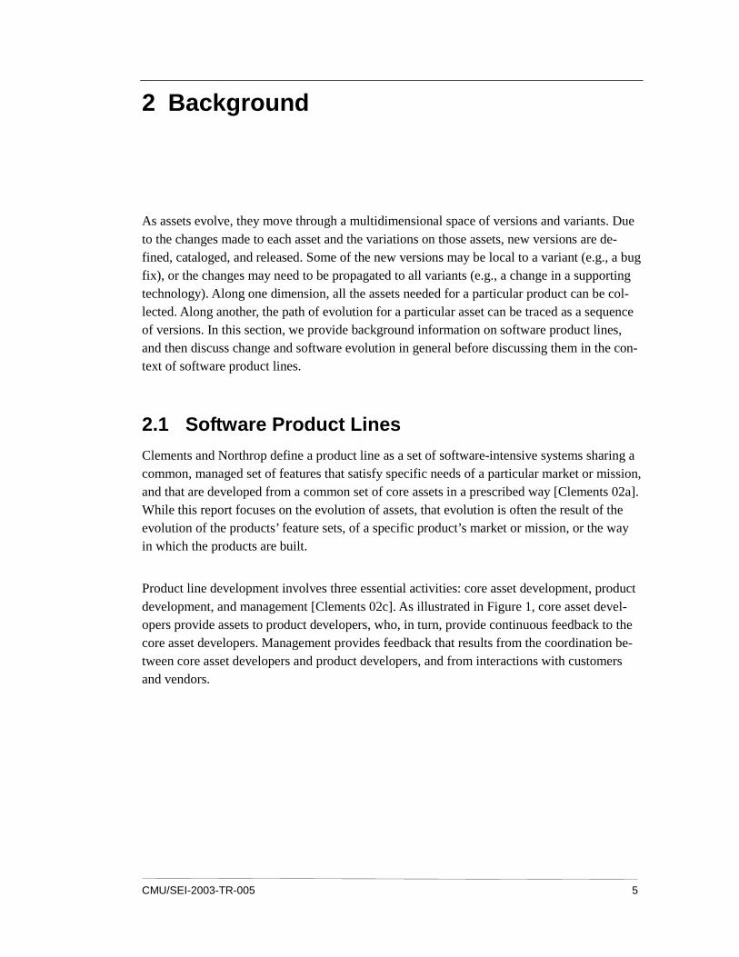
As assets evolve, they move through a multidimensional space of versions and variants. Due to the changes made to each asset and the variations on those assets, new versions are de-fined, cataloged, and released. Some of the new versions may be local to a variant (e.g., a bug fix), or the changes may need to be propagated to all variants (e.g., a change in a supporting technology). Along one dimension, all the assets needed for a particular product can be col-lected. Along another, the path of evolution for a particular asset can be traced as a sequence of versions. In this section, we provide background information on software product lines, and then discuss change and software evolution in general before discussing them in the con-text of software product lines.
2.1 Software Product Lines
Clements and Northrop define a product line as a set of software-intensive systems sharing a common, managed set of features that satisfy specific needs of a particular market or mission, and that are developed from a common set of core assets in a prescribed way [Clements 02a]. While this report focuses on the evolution of assets, that evolution is often the result of the evolution of the products’ feature sets, of a specific product’s market or mission, or the way in which the products are built.
Product line development involves three essential activities: core asset development, product development, and management [Clements 02c]. As illustrated in Figure 1, core asset devel-opers provide assets to product developers, who, in turn, provide continuous feedback to the core asset developers. Management provides feedback that results from the coordination be-tween core asset developers and product developers, and from interactions with customers and vendors.

6 CMU/SEI-2003-TR-005
Figure 1: Product Line Activities
These activities are described in more detail by the set of 29 software product line practice areas defined in A Framework for Software Product Line Practice, V4.1 [Clements 02c]. The practices contribute to the evolution of assets and products in different ways. Specific prac-tice areas are called out at the appropriate places in this report to illustrate their use in initiat-ing and managing evolution. They are not described in detail here.
Consider a manufacturer of what are now called wireless devices but were, in recent memory, termed cell phones. These devices have evolved from bulky, briefcase-sized devices that pro-vided basic telephony services to shirt-pocket-sized devices that compete with low-end per-sonal computers in terms of the range of services they provide. Companies now produce mul-tiple models with a variety of options, while still maintaining the core functionality of a mobile radio transceiver that communicates with a fixed transceiver.
Several manufacturers of these devices have adopted a product line approach to specify and construct their products. The many models with closely related feature sets fit well with the assumptions and goals of product line development. The current development environment for the control software is a complex blend of software written in several languages—some of it acquired from outside vendors and all of it changing. We have to wait and see how evo-lution affects this type of product line.
2.2 External Forces for Change
External forces are one impetus for change in the product line organization. The forces de-fined in Porter’s Five Forces business strategy development model, shown in Figure 2, pro-vide a high-level framework for identifying external initiators of evolution [Porter 98].

CMU/SEI-2003-TR-005 7
• Potential entrants into the market might force a change in the fundamental business strategies of the organization. Such a change might cause corresponding changes in the product line strategy, the architecture, and related assets. Telephony, from which wireless devices have evolved, was a hardware-intensive business with only enough attention to software to drive the hardware. Now, features and services drive the sales of devices, and both are provided predominantly in software.
• Industry competitors might force a change in assets by leading efforts to change domain standards or by introducing a disruptive technology into a previously stable market. By rapidly adding new features, wireless competitors have forced a succession of new com-munication protocols to be developed and adopted. New products must implement the latest standard or not be accepted in the marketplace.
• Substitutes for products of the product line might force change by adopting new tech-niques that allow the substitutes to be offered at significantly reduced prices or delivered more quickly than is standard. Wireless service providers have adopted the practice of giving away low-end phones with service contracts. Doing so forces the manufacturer to become much more price competitive by reducing manufacturing costs.
• Buyers might force change by demanding the latest technology in the products they buy. The average wireless user changes devices every 18 months.
• Suppliers might force change by discontinuing or evolving the assets they provide to the product line. Suppliers in the wireless market are under the same competitive pressure as the manufacturers and change rapidly to track the market changes.
Potential Entrants
Substitutes
Buyers Suppliers Industry Competitors
Threat of Substitute Products or Services
Threats of New Entrants
Bargaining Power of Suppliers
Bargaining Power of Buyers
Figure 2: Porter’s Five Forces Model

8 CMU/SEI-2003-TR-005
2.3 Internal Forces for Change
The interactions identified in Figure 1 among the three product line activities result in inter-nal forces for evolution. We consider the influence of each activity on the others.
2.3.1 Core Asset Developers
Core asset developers exert evolutionary force on the product developers by providing new versions of assets and additional variants. The product developers have to expend effort to understand the new processes, procedures, and interfaces. Frequent releases with trivial changes will consume many development resources with little gain. Waiting too long to re-lease a new version of an asset can allow product teams outside the developing organization to “clone and own” the best-fitting asset and adapt it to their needs.
Core asset developers also exert evolutionary force on management to provide technology forecasts. These forecasts help core asset developers plan which assets to retire, which to in-vest additional work in, and which to schedule for development. Waiting too long to decide on new technologies can force delays in products or require the product development teams to custom create components that must be redesigned later for product line use.
2.3.2 Product Developers
Product developers exert evolutionary force on the asset developers by providing change re-quests on existing assets. Despite the tests run by the core asset team, defects will become apparent in use. Product developers also exert evolutionary force by nominating some of their custom-designed components to be renovated as core assets. Product developers provide other feedback (such as use reports) that influences the core asset developers when maintain-ing assets.
The product developers exert evolutionary force on management by identifying potential products. Management responds by analyzing the scope and business plan for new opportuni-ties. Product developers also exert force on management to change how schedules are esti-mated. As product development matures, patterns of product development evolve and are used for estimation.
2.3.3 Management
Management exerts evolutionary force on the asset developers by periodically updating tech-nology forecasts and adjusting the business plan for the product line. Asset developers re-spond to these forces by updating existing assets or creating new ones. Core asset developers also revise the product line scope to accommodate the new products built from the new as-sets.

CMU/SEI-2003-TR-005 9
Management exerts evolutionary force on the product builders by modifying the business case and the product line scope. Doing so may change the interval between products or at least reprioritize them. Management may also revise the risk analysis causing the product builders to revise the production plan.
2.4 Software Evolution
All software evolves, not just product line assets. Without the product line organization to control and direct the evolution, it is more likely that the evolution will be unanticipated and chaotic, and that the quality and integrity of the product line will erode. Lehman and col-leagues established a set of “laws” that govern software evolution [Lehman 98]. While there is little quantitative support for the laws, there is much experiential support. Below, we con-sider each law in the context of a software product line and the evolution of its assets.
1. Systems must be adapted continually; otherwise they become progressively less satisfac-tory in use. The software product line organization provides a feedback mechanism from product developers1 to core asset developers that allows the latter to adapt to the changing con-text. The “Architecture Evaluation” practice area is applied repeatedly to ensure the con-tinuing consistency and relevance of the architecture.
2. As a system is evolved, its complexity increases unless work is done to maintain or re-duce it. Having the core asset developers maintain the various core assets (including software components and the production plan that describes how to assemble a product using the assets) provides a single analysis point for this complexity. The modularity of the core assets makes it easier to identify and reduce incidental complexity within the narrow scope of an individual asset.
3. Global system evolution processes are self-regulating. The interaction of the three roles—core asset developer, product developer, and man-ager—regulates the degree to which product line assets change. The processes of the other two groups mediate individual changes proposed by one group. For example, the core asset group evolves an asset only to the degree that is useful to the product builder and is within the financial parameters defined by managers.
1 Those who are assigned a role in one of the essential activities can be organized in a variety of
ways. For that reason, we discuss roles here rather than teams or units. An individual might be as-signed one or more of these roles. A core asset developer, for example, may also be a product de-veloper.
10 CMU/SEI-2003-TR-005
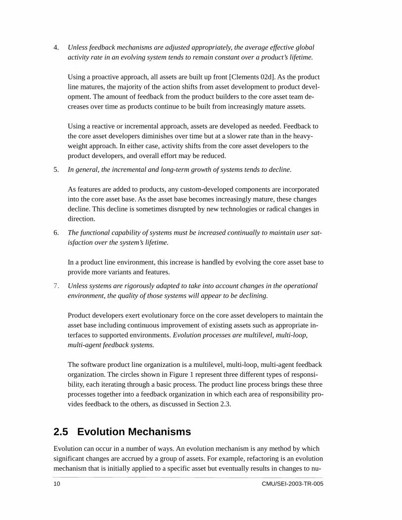
4. Unless feedback mechanisms are adjusted appropriately, the average effective global activity rate in an evolving system tends to remain constant over a product’s lifetime. Using a proactive approach, all assets are built up front [Clements 02d]. As the product line matures, the majority of the action shifts from asset development to product devel-opment. The amount of feedback from the product builders to the core asset team de-creases over time as products continue to be built from increasingly mature assets. Using a reactive or incremental approach, assets are developed as needed. Feedback to the core asset developers diminishes over time but at a slower rate than in the heavy-weight approach. In either case, activity shifts from the core asset developers to the product developers, and overall effort may be reduced.
5. In general, the incremental and long-term growth of systems tends to decline. As features are added to products, any custom-developed components are incorporated into the core asset base. As the asset base becomes increasingly mature, these changes decline. This decline is sometimes disrupted by new technologies or radical changes in direction.
6. The functional capability of systems must be increased continually to maintain user sat-isfaction over the system’s lifetime. In a product line environment, this increase is handled by evolving the core asset base to provide more variants and features.
7. Unless systems are rigorously adapted to take into account changes in the operational environment, the quality of those systems will appear to be declining. Product developers exert evolutionary force on the core asset developers to maintain the asset base including continuous improvement of existing assets such as appropriate in-terfaces to supported environments. Evolution processes are multilevel, multi-loop, multi-agent feedback systems. The software product line organization is a multilevel, multi-loop, multi-agent feedback organization. The circles shown in Figure 1 represent three different types of responsi-bility, each iterating through a basic process. The product line process brings these three processes together into a feedback organization in which each area of responsibility pro-vides feedback to the others, as discussed in Section 2.3.
2.5 Evolution Mechanisms
Evolution can occur in a number of ways. An evolution mechanism is any method by which significant changes are accrued by a group of assets. For example, refactoring is an evolution mechanism that is initially applied to a specific asset but eventually results in changes to nu-
CMU/SEI-2003-TR-005 11
merous assets [Opdyke 92]. In Section 4, we discuss a number of such mechanisms in the context of a software product line. A working group of the First International Workshop on Unanticipated Software Evolution constructed a taxonomy of attributes for software evolu-tion mechanisms [Kniesel 02]. We use the four dimensions of the taxonomy to discuss the types of changes that result in the evolution of a product line.
2.5.1 Properties of the Change Mechanism
When is the mechanism applied? An artifact is changed at times determined by the type of artifact and the processes that affect the artifact. The core asset developers might establish a schedule of regular releases of asset revisions, or assets might be replaced whenever modifi-cations are completed. The evolution mechanisms are incorporated in the asset and product development processes so that regularly scheduled changes are handled routinely.
How automatic is the mechanism? Changes vary in the degree of automation available to support modifications. For example, automatic documentation tools, such as javadoc, can automatically change documentation to match software components that have been changed manually to meet a new architecture requirement [Sun 03]. The relationships among product line assets are long-lived and used often. Spending time to support automation, with actions such as inserting specific tags, is worth the extra time. It makes these relationships accessible via tools such as repository search agents, asset catalogers, and variation managers.
How formal is the mechanism? Standards organizations have well-defined processes for changing a standard. This gives using organizations ample opportunity to plan for deploying the new standard. Community standards such as J2EE and others provide the same anticipa-tion of change. Changes that must be approved by a local change control board are less for-mal and can happen much more rapidly.
2.5.2 Properties of the Change Itself
The change can affect either the form or meaning of an asset. Changes to the architecture typically modify its structure and attributes. Changing from one implementation to another for a specific interface changes only the form of the product and not its meaning. Changing the content of an interface is a change in meaning. Changes in form exert evolutionary force on those assets that rely on the qualities of the changed asset’s implementation. Changes in meaning exert evolutionary force on all assets related to the modified asset.
The scope of the change might be defined so narrowly that only a single asset is affected or so broadly that most assets are affected. Some changes, such as the introduction of a new driving requirement for the product line, affect a large number of the assets in a product line. Other changes, such as a single change to a local data structure, affect only a single asset. And while some changes (such as changing the line spacing in a document) affect most of an

12 CMU/SEI-2003-TR-005
asset, others (such as changing the font for all level-three headings) affect only isolated parts of it.
The change may add to, subtract from, or modify the existing content of the asset. Removing a product line asset requires that all remaining dependencies be satisfied by some alternative asset, or by modifying or removing the other asset participating in the dependency. The ef-fects of modifying an asset must be propagated to all dependencies where those effects will be evaluated and handled. These dependencies include other assets as well as products built using the assets.
2.5.3 Properties of the System
The system can be either open or closed. An open system is created with the philosophy that it will be integrated with other systems to make larger more powerful applications. A closed system is developed to be self-contained. Changes to the interfaces of a closed system are easier to accomplish than for an open system, since the concern is limited to internal consis-tency. Typically, open systems must conform to some level of interface or architecture stan-dard.
The degree to which a system exposes its interfaces to product builders is a key property of a system. In a product line, the interfaces that will be exposed to product builders must be con-trolled, and evolution of those interfaces will affect product builders as well as asset develop-ers. The interfaces that are internal to the pieces delivered by the core asset team are hidden and managed locally. Product lines built using a “platform2” approach are less subject to evo-lution, since only a few of the interfaces are exposed to product builders.
2.5.4 Properties of the Change Process
The change process can have a regular rhythm or operate on demand. Agile development methods define a rhythm in which new releases are planned to occur at specific times regard-less of the amount of new functionality that is ready for delivery [Martin 03]. Other changes, such as a supplier discontinuing a component, happen spontaneously. The “Technology Fore-casting” and “Technical Risk Management” practice areas of a product line effort tend to re-duce the amount of unplanned change [Bosch 02].
The change process can be controlled or uncontrolled. The product line practice area “Con-figuration Management” describes a comprehensive approach that provides change control down to a low level of detail. The “Technical Planning” practice area describes how change control is incorporated into the overall product line approach. Uncontrolled change can have
2 A platform is typically a monolithic module that provides a fixed set of services. The Unix kernel
is a very low-level platform.

CMU/SEI-2003-TR-005 13
a magnified effect on products in a product line. The multiple uses of an asset in a product line tend to propagate any change made to the asset to the many products that use that asset. Section 5.4.1 discusses this in more detail.

14 CMU/SEI-2003-TR-005

CMU/SEI-2003-TR-005 15
3 Concepts of Product Line Evolution
Evolution in a software product line is complicated by the fact that evolution of a single asset can affect many other assets and multiple products.
• Many relationships exist among assets in the asset base of a software product line, such as the relationship between the goals in the business case and the structure of the produc-tion plan.
• Creating a product involves the use of many assets, some of which might be derivations of other assets such as the instantiation of the production plan template.
• One asset might constrain the design or structure of another such as the constraints on the architecture that originate in the business case.
• Changes made to one asset are propagated to other assets such as when changes to the business case result in changes to the architecture and production plan.
In this section, we present a number of basic concepts related to evolution in a software prod-uct line. We also relate these concepts to the evolution plan for an asset.
3.1 Specifying the Direction of Evolution
Evolution is “a process of change in a certain direction” [Merriam-Webster 93]. The direction can be toward any specific goal. Svahnberg & Bosch specify evolutionary tracks that lead in the direction of increased maturity [Svahnberg 99]. A set of assets might evolve toward com-pliance with a new standard. The challenge is to move all of them in the same direction when each has its own dependencies and constraints.
When evolution is planned, a specific objective is set and a plan is formed for how to achieve it. For example, let’s say that compliance with a new standard is set as an objective. The evo-lution’s scope and cost are evaluated through the change impact analysis described in Section 5.3.5. This analysis determines which changes are needed to achieve the objective and begins with an architecture evaluation. A plan for how to change the affected assets is then devel-oped.
Specifying the direction of evolution is integral to developing the evolution plan. The specifi-cation involves understanding two things: (1) the objective and (2) the current configuration

16 CMU/SEI-2003-TR-005
of each asset that must be changed. For example, if the assets currently conform to a standard and the objective is to be conformant to a new version of it, the necessary changes will be different from the case where the assets already follow a similar behavior but are not confor-mant to any standard. The evolution plan specifies how each asset will be moved from its current configuration to the objective configuration.
When evolution is due to a change to the architecture, the direction of evolution is specified as a move from one architectural structure to another, or as a directed change in the value of certain quality attributes. Often, this is specified as a change to one or more interfaces radiat-ing out from the site of the initial change. By conducting a change impact analysis prior to making changes, alternatives can be examined to limit the scope of the evolution.
The direction is specified in units that make sense for the type of evolution. It can be stated in terms of the current and desired content of interfaces, the current and new content for a document, or the current and desired levels of an attribute. The starting point is explicit in this definition, because it is necessary for estimating the effort required for the evolution.
For the wireless device example, a likely evolution is that the procession of products will progress through a series of communication protocols with each product using the currently popular protocol. The effort needed to reach that goal will depend on the protocol used in the last few products and how closely related it is to the new protocol. The scope of the evolution will be determined by how isolated the “protocol stack” is from the remainder of the product. The evolution plan would specify the direction of evolution as a progression of protocol defi-nitions defined by a series of increasingly complex state machines. The plan would also in-clude goals for the architects to isolate the protocol stack and to design for exchanging one protocol for another.
3.2 Influences on Evolution
The structure and organization of a software product line affects the evolution of its assets. As seen in Table 1, the amount of up-front planning and architecture work makes unanticipated evolution less likely than in a custom system. Unexpected evolution can’t be totally elimi-nated because it is caused, in part, by forces outside the control of the product line organiza-tion.

CMU/SEI-2003-TR-005 17
Table 1: Anticipated Versus Unanticipated Evolution
Product Line Product Custom Product
Anticipated Evolution Very likely. Variation among products is central to product line design.
Possible; requires careful planning; usually occurs in a single domain where the company has expertise
Unanticipated Evolution Less likely. Technology fore-casting looks ahead. Plan-ning at many levels antici-pates change.
Very likely; usually no plan-ning. The design satisfies the current need.
3.2.1 Software Product Line Practice Areas
Three software product line practice areas are primary influences on the mitigation of antici-pated evolution:
1. Technology Forecasting—enhances the possibility that any evolution will be anticipated and proactively searches for changes related to advances in the technologies that are used to implement the products in the product line
2. Understanding Relevant Domains—provides an understanding of which features are most likely to change
3. Market Analysis—provides an understanding of which existing products will become obsolete and which new products are likely to be successful
The above practice areas impact two assets directly: (1) the business case and (2) the product line scope. The business case evolves to reflect new risks and new competitors. The scope might evolve to reflect changing market conditions or in response to emerging technologies.
The “What to Build” product line pattern guides an organization in using these product line practices and others to develop an offense against anticipated evolution [Clements 02a].
3.2.2 Unanticipated Evolution
Several events external to the product line organization lead to unanticipated evolution in-cluding
1. Organizational and technical managers sometimes make decisions that are justified po-litically rather than objectively, leading to unpredictable changes and eventually to unan-ticipated evolution.
2. Although business cycles can be predicted, the effects of their changes cannot always be. Resource reductions “across the board” in a company can trigger unanticipated evolu-tion.

18 CMU/SEI-2003-TR-005
3. Technology cycles do not always run their course. In some cases, disruptive technolo-gies gain rapid, widespread acceptance forcing unanticipated changes in products.
3.2.3 Organizational Influences
The degree of autonomy of the product line organization affects the amount of unanticipated evolution. The first product line effort in a subunit of a multinational company might not have sufficient autonomy to prevent the parent company from changing the products in the product line. Smaller, more sharply focused, organizations might be able to keep the amount of unanticipated change very low.
3.2.4 Type of Personnel
A product line organization needs both domain-savvy and technically savvy personnel. Do-main-savvy personnel spend more time on the “Understanding Relevant Domains” practice area and less on the “Architecture Definition” and “Component Development” practice areas. This allocation of effort leads to more unanticipated evolution at the individual asset level, since the personnel keep developing new ways of thinking about the concepts represented in the assets and less evolution at the product level. When the balance shifts to more technically savvy personnel and more time is spent on product-structuring practices such as “Architec-ture Definition,” the opposite occurs. The organization can guard against these biases by en-suring adequate coverage of all the practice areas when assigning responsibilities and defin-ing processes.
Consider the organization in the wireless device example. Usually, the personnel in a wireless design organization are more domain savvy, due in part to two things: (1) the rapid evolution of wireless devices and (2) the fact that most of the personnel come from traditional engineer-ing disciplines such as electrical engineering as opposed to software engineering back-grounds. For this reason, more attention will be paid to changing communication standards and requirements unless the organization explicitly addresses areas such as architecture and product production.
3.3 Evolution Propagation
Svahnberg and Bosch define an evolution process, outlined in Figure 3, that traces the effects of a change through assets [Svahnberg 99]. In the top left-hand corner of the illustration, a business unit initiates changes in product-specific requirements. Those changes are then propagated to the product line architecture. The changes to the architecture, in turn, cause changes to some of the product components and to products built from the architecture. In fact, change can be injected at any point in this flow and be traced through the other assets.

CMU/SEI-2003-TR-005 19
Business Unit
Products
Product Line Requirements
Specific Component
Product Line Architecture
Time
Business Unit
Products
Product Line Requirements
Specific Component
Product Line Architecture
Business Unit
Products
Product Line Requirements
Specific Component
Product Line Architecture
Business Unit
Products
Product Line Requirements
Specific Component
Product Line Architecture
Figure 3: Evolutionary Life Cycle of a Product Line (Adapted from Svahnberg and Bosch’s Work [Svahnberg 99])
All assets evolve, not just the software assets. Figure 3 shows dependencies among product line assets that provide pathways for the propagation of evolutionary forces.

20 CMU/SEI-2003-TR-005
Table 2: Propagation Paths
Will Propagate to Here Changes Made Here business
case scope architecture components production
plan test plan
business case � � � � �
scope � � � � �
architecture � � � �
components � � �
production plan � �
test plan
3.3.1 The Product Line’s Scope
The scope of the product line can evolve over time either to include additional products that were not included in the original definition or to remove some of the original products. If the scope evolves, it might, in turn, cause other assets to evolve. If new products are added to the product line, the software architecture might need to evolve to support additional variants and result in the evolution of components to fit the architecture’s new decomposition. Removing products from the scope does not necessarily cause other lower level assets to evolve, but it does cause the economics of the business case to change.
The scope of the product line—a high-level view—is one of the fundamental assets. The re-sult of its high-level, encompassing nature is that changes to the scope have far-reaching in-fluence on the evolution of other assets. Techniques such as domain analysis and other tech-niques that identify abstractions are a useful defense against evolution of scope.
3.3.2 Software Architecture
The ability to evolve is one of the architectural attributes discussed by Bass, Clements, and Kazman [Bass 03]. The degree to which an architecture can evolve can be evaluated using the Architecture Tradeoff Analysis MethodSM (ATAMSM) [Clements 02b]. Changes to an ev-olvable architecture sets off ripples that follow the arrows in Figure 3 and force other assets to change.
Svahnberg and Bosch list the following categories of architecture evolution [Svahnberg 99]:
• split of the product line architecture
• derivation of a product line architecture from an existing one
SM Architecture Tradeoff Analysis Method and ATAM are service marks of Carnegie Mellon Univer-
sity.

CMU/SEI-2003-TR-005 21
• new components required
• changed components
• replacement of a component
• split of a component
• new relationship between components
• changed relationship between components
The architecture also evolves with respect to the features it supports; it can evolve to handle additional or fewer features. The addition of features will probably require the addition of interfaces as well, leading to additional components and unit test plans. This evolution might change the production plan or the tools that automate it.
3.3.3 Documents and Plans
In modern processes for software development, models, designs, and documents all evolve. Typically, they evolve toward being more complete and detailed, which is a natural occur-rence in an iterative development process. Even though it is natural, it can still introduce in-consistencies when multiple changes occur.
Often, documents must evolve in two dimensions: (1) they become more complete as person-nel take time to incorporate more detail and (2) they must be updated to reflect changes to related assets. For example, the documentation for a software asset is tightly linked to that asset and evolves in parallel with changes to the asset. Oftentimes, initial versions of the documentation do not contain the full details of the asset.
Plans for an activity precede its occurrence, the assets used in it, and its output. When a plan evolves, it initiates ripples through these assets, activities, and outputs. For example, the product line test plan begins as a general outline and evolves until it contains the specific test cases that will be executed.
The use of template master documents and techniques that separate the document’s content from its format are good defenses against evolution. Changes are then limited to the abstrac-tion, the template or document type definition (DTD), or the content used to complete the abstraction.
3.3.4 Software Modules
Much has been written on software evolution including Lehman’s laws for different types of systems, which are discussed in Section 2.4 [Lehman 98]. In a product line, the opportunities

22 CMU/SEI-2003-TR-005
and difficulties surrounding software evolution are magnified. The large number of depend-encies between assets in a product line requires much attention and effort.
Component-based development techniques provide very good support for evolution in a product line context. Separating the component’s specification from its implementation al-lows the latter to evolve independent of its specification. Component techniques allow the necessary implementations to be bound to a product as late as the product’s execution time to achieve specific product qualities.
3.4 Risks of Evolution
Risks to the success of the product line that result from evolution include
• consistency—As changes accumulate, related assets might be changed in different direc-tions and no longer be compatible. Planning for evolution by specifying its direction and designing defensively should mitigate this risk. These evolution plans are propagated to all related assets. An evolution plan is then created for each related asset. If a constraint prevents a consistent change to a related asset, the process must be rolled back so that an alternative can be tried.
• completeness—Given changes to a large number of assets, an association could poten-tially be lost or rerouted during evolution, resulting in an asset being omitted from a con-figuration and blocked from further changes. Periodically inspecting the output of a change process and comparing it to the input can mitigate this risk. Sometimes, the result of an evolutionary ripple is the removal of assets. This result should be specified clearly in the evolution plan.
• correctness—Changing an asset might introduce a defect into it. Specifying the direction of evolution to include a design for the change can mitigate this risk. Changes to assets should undergo the same inspection as the original asset.

CMU/SEI-2003-TR-005 23
4 Implementing Evolution
4.1 “Evolve Each Asset” Pattern
Clements and Northrop define a product line pattern called Each Asset3 and a variant for it called Evolve Each Asset [Clements 02a. That variant, illustrated in Figure 4, describes the evolution of an asset. In that figure, PA* refers to the product line practice areas that are needed to evolve the specific asset. These practice areas vary from one type of asset to an-other. For example, if the asset to be evolved is the product line architecture, PA* would be the “Architecture Definition” practice area.
Tested, Baselined Asset w/Attached Process PA*
Tool Support Process Definition
Technical Planning
Data Collection, Metrics, and Tracking
Configuration Management
Testing
Tools
Attached Process
Test Cases
CM Process Data Work Plan
Progress and Changes
Work Plan
Figure 4: “Evolve Asset” Pattern
The practice areas listed explicitly in the pattern are those that initiate, control, or validate the evolution:
• Any modification to a core asset requires a work plan. The “Technical Planning” practice area provides the skills and techniques needed to develop a work breakdown structure
3 Software product line practice patterns give common product line problem/solution pairs in which
the problems involve product line work to be done and the solutions are the groups of practice ar-eas to apply in concert to accomplish that work.

24 CMU/SEI-2003-TR-005
that allows the engineer to scope and estimate the work. The evolution plan is described in Section 4.2.2.
• The “Data Collection, Metrics, and Tracking” practice area provides the data, techniques, and algorithms that support the estimation and tracking of progress against the plan. The central practice area, PA*, generates data that can be used to evaluate the quality of the evolution. Metrics for evolution are discussed in Section 4.3.
• The practice area indicated by PA* requires tools to modify the asset. Generally, the same tools used to build an asset would be used to evolve it. A sufficient change to the asset may require new tools. Conceptual tools for evolution are discussed in Section 5.3; automated tools are discussed in Section 5.4.
• The evolved asset will be tested to determine its quality. The test activity may be a dy-namic execution (if the asset is a piece of code) or a static inspection (if the asset is a document or model). Testing for evolved assets is discussed in Section 4.4.
• If the asset’s evolution causes a change in the technology behind the asset, a new attached process for the evolved asset might be needed. In that case, it can be created using the “Process Definition” practice area as a guide. Defining attached processes is discussed further in Section 4.5.
• The evolved asset will eventually be assigned a version number, placed under configura-tion management, and made available. Owners of existing configurations will be given the opportunity to upgrade to the latest version. Configuration management techniques for evolution are discussed in Section 5.4.1.
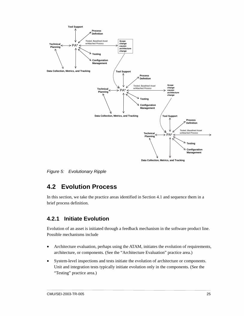
For example, consider changing a product line’s business case (i.e., PA* is the “Building a Business Case” practice area) because of greatly reduced labor costs. Instructions for chang-ing the business case would be described in a process attached to it. A work plan might be developed to define the tasks for revisiting the “Market Analysis” and “Requirements Engi-neering” practice areas. A new version of the business case is released. Changing the business case initiates an evolutionary ripple that applies the “Evolve Asset” pattern to the “Market Analysis” and “Requirements Engineering” practice areas, as shown in Figure 5.
CMU/SEI-2003-TR-005 25
Tested, Baselined Asset w/Attached Process
PA*
Tool Support
Process Definition
TechnicalPlanning
Data Collection, Metrics, and Tracking
Configuration Management
Testing
Tested, Baselined Asset w/Attached Process
PA*
Tool Support
Process Definition
TechnicalPlanning
Data Collection, Metrics, and Tracking
Configuration Management
Testing
Scope change causes architecture change
Tested, Baselined Asset w/Attached Process
PA*
Tool Support
Process Definition
TechnicalPlanning
Data Collection, Metrics, and Tracking
Configuration Management
Testing
Scope change causes architecture change
Figure 5: Evolutionary Ripple
4.2 Evolution Process
In this section, we take the practice areas identified in Section 4.1 and sequence them in a brief process definition.
4.2.1 Initiate Evolution
Evolution of an asset is initiated through a feedback mechanism in the software product line. Possible mechanisms include
• Architecture evaluation, perhaps using the ATAM, initiates the evolution of requirements, architecture, or components. (See the “Architecture Evaluation” practice area.)
• System-level inspections and tests initiate the evolution of architecture or components. Unit and integration tests typically initiate evolution only in the components. (See the “Testing” practice area.)

26 CMU/SEI-2003-TR-005
• User feedback initiates evolution in a product, particularly its requirements. (See the “Customer Interface Management” practice area.)
• Feedback from product builder to core asset builder can initiate the evolution of any core asset. (The attached process of the practice area that created the asset will define the steps for evolving the asset.)
The initiating mechanism provides information about the proposed change and might identify several possibly related changes during one use.
4.2.2 Develop an Evolution Plan
The feedback is analyzed to determine whether there should be several independent changes or just one coordinated attack. For each change, the primary asset to be evolved is identified. A change impact analysis is conducted to scope the evolution effort. That is, the analysis will identify all those assets that must be modified as a result of changing the primary asset. The standard maintenance metrics of the organization are used to cost the effort. If the cost of the evolution is considered to be feasible, a plan is developed for the evolution. The plan might allow for the concurrent modification of assets or indicate that one asset’s modification is a prerequisite for another’s.
4.2.3 Apply Transformations
The evolution plan identifies the transformations (see Section 5.1) that will be used to modify each asset. These transformations are intended to achieve the objectives of the evolution plan such as an additional service or an enhanced quality. Applying transformations to one asset might lead naturally to the transformation of others identified during the change impact analysis. In addition, they can lead to the revision of an asset’s attached process to fit the as-set’s new characteristics (see the “Process Definition” practice area). For example, changing an asset might change how products that use that asset are built.
4.2.4 Accept the Evolved Assets
The evolution plan defines the testing activities that determine whether the newly modified asset is consistent with the other core assets. If it is, it’s placed under configuration control. The evolution plan might call for the immediate update of several existing configurations (e.g., if defect repairs are needed), or the asset might be incorporated in a new configuration (e.g., in a new version of the product or through its use by another asset).

CMU/SEI-2003-TR-005 27
4.3 Evolution Metrics
Mens and Demeyer define software evolution metrics, identify areas of future research, and define the following three categories of software [Mens 01]:
1. evolution-critical parts—parts of the design or software that need to be evolved because of existing problems. For example, Simon, Steinbruckner, and Lewerentz define a metric that identifies the need for different types of refactoring (see Section 5.3.1) [Simon 01].
2. evolution-prone parts—parts of the design or software that are likely to evolve because the corresponding requirements are likely to change. The “Technology Forecasting” practice area provides metrics for identifying requirements that are likely to change.
3. evolution-sensitive parts—parts of the design or software that will be expensive to evolve. For example, in object-oriented software, the depth metric identifies classes that are near or at the top of inheritance hierarchies. The higher the class is, the higher the number of dependencies and the wider the ripples will be if the class is chosen for evolu-tion.
4.4 Testing During Evolution
Assets are tested as they are created. The “Testing” practice area describes how and includes defining the test plans, test cases, and test data in ways that make their reuse practical.
Testing evolved assets is an incremental activity. It assumes that a change impact analysis (see Section 5.3.5) has been conducted. Testing in the presence of evolving assets involves five tasks:
1. Locate the test assets for the evolved asset. The configuration management system should contain validation information for each asset and its relationships to other assets.
2. Conduct an incremental test analysis, using the results of the change impact analysis, to determine which facets of the asset have changed, such as its specification or implemen-tation.
3. Select the tests that correspond to those changed parts or to any specification whose im-plementation has changed. Those tests that correspond to changed parts are modified when the asset is modified.
4. Modify the selected test assets to reflect the changes to the evolved asset.
5. Conduct those tests selected during the incremental analysis and report their results.

28 CMU/SEI-2003-TR-005
4.5 Attached Process Definition
Each asset has an attached process that defines how it can be used. When an asset is changed, its attached process is reviewed to determine whether it should be modified as well. The process defines the constraints associated with the asset, such as which tools can be used on it and the compiler flag settings that must be used to build it.
Certain types of changes to the asset map directly to changes in the attached process. Porting an asset from one environment to another leads directly to changes in how the asset is used. For example, if documentation’s format is changed, a new tool might be required to view it.
Other changes might affect the attached process indirectly by changing related assets. For example, one change could introduce circular references among several assets, making it im-possible to build one of those assets.
The attached process is considered to be part of the production plan. When an asset’s attached process is changed, the production plan changes too, so it should be reviewed for consistency. Changes to the production plan can cause ripples that affect how products are built. The changes might even increase an organization’s flexibility to build products.

CMU/SEI-2003-TR-005 29
5 Support for Evolution
Support for evolution comes in the form of both conceptual techniques (which can be proac-tive or reactive) and automated tools. The proactive techniques are used to construct assets that can anticipate evolution. Other reactive techniques are used when the need for evolution arises.
In this section, we first consider notations for describing evolution and then consider the techniques and tools used to support it.
5.1 Notation for Evolution
No notation for illustrating evolution has received widespread acceptance as of yet. France and Bieman, and Mens and Demeyer describe extensions to the Unified Modeling Language (UML) for modeling evolution [France 01, Mens 00]. The transformations described by France and Bieman are discussed in Section 5.3.4. These notations make use of the stereotype mechanism in UML. Labels defined as ���������� are used to identify elements in dia-grams that share a set of well-formedness rules. This extends UML to include the concept of evolution.
Because evolution happens over time, the vocabulary used in evolution notations must ex-
press temporal relationships such as the ���� relationship in the France and Bieman notation. This relationship expresses that a model, or some portion of it, was developed from another.
Mens and Demeyer use the concept of an EvolutionContract to denote a relationship between two models or model entities. This relationship is expressed through four basic stereotypes that modify NameSpaces:4 (1) ��� , (2) �� ���� , (3) ����� , and (4)
������� . Two composite stereotypes that operate on EvolutionContracts are also used: (1) ��� ��� and (2) ������������ . Promotion defines high-level EvolutionContracts in terms of lower level ones. Sequentialization defines an EvolutionCon-tract that is based on an ordered list of smaller EvolutionContracts.
4 A namespace is a set of names that are unique within the set. Modeling and programming lan-
guages have semantics for defining namespaces.
30 CMU/SEI-2003-TR-005
The extensions suggested by France and Bieman, and Mens and Demeyer illustrate the fol-lowing points about evolution notations:
• An evolution notation must provide relations between a base model and the evolved model.
• The evolution notation must be broad enough to represent a diverse set of transforma-tions such as changing levels of abstraction and moving from specification to implemen-tation.
5.2 Asset Development Techniques
In this section, we consider some proactive techniques for supporting evolution.
5.2.1 Design for Evolution
Assets should be designed to accommodate the evolution that is inevitable. The Eclipse inte-grated development environment has been designed around a plug-in architecture [Eclipse 03]. The environment can be extended with new functionality, and the existing functionality can be modified by defining new plug-ins. As the product line organization identifies new tools, they can be added to the environment.
Design techniques such as abstraction, genericity, modularity, and information hiding support evolution. Each technique is described below.
Abstraction defines a scope within which additional definitions can be added with little ef-fort. Abstraction is useful at many levels in the core asset base. Interfaces in the product line architecture provide an abstraction from the specific component implementations. This type of abstraction allows for variations in quality attributes while maintaining a common struc-ture overall. In an object-oriented design, an abstract class at the top of the inheritance hierar-chy allows new class definitions to be added below it incrementally. Often, those definitions can be substituted for classes defined above the new one without any modification to the us-ing code. A similar property holds for the DTDs that define the structure of Extensible Markup Language (XML) documents. One DTD can be derived from another, while retaining attributes of the original DTD. This allows documents to evolve incrementally.
Genericity provides the ability to specify a set of related definitions but with more restrictions than typically possible with abstraction. The template mechanism, found in programming languages, allows for the rapid definition of new classes through instantiations of the tem-plate. Genericity is used heavily for document definition. For example, the structure of stan-dard plans is captured in templates and then instantiated as needed. Component and product
CMU/SEI-2003-TR-005 31
test plans are examples of documents that are created over time and have a sufficiently stan-dard structure to benefit from genericity.
Modularity defines a unit that is loosely coupled with other units but whose content is very cohesive. The earlier example of a Java package is a modular structure. Modularity allows the easy replacement of one unit with another. Using a component-based approach to the de-sign of the architecture facilitates evolution through the use of modularity. The use of cross-references in documents reduces redundancy in the documents and makes the information they contain more maintainable. Chapters and sections are document modules that can be linked yet remain independent.
Information hiding limits the potential impact of a change by restricting references that create dependencies between assets. For example, the automated production plan for a product line hides the details of the program assets from the product builder. When such assets are changed, the product builder does not have to know about or change any behavior unless the modification also changes the attributes that were selected during product creation.
The product line organization should select technologies that support these conceptual tools. Word processors support both template development and the linking together of independent modules through hyperlinks. Presentation tools allow links for assembling documents on re-quest automatically rather than statically. Such links help guarantee that readers see the latest information. Software development tools such as Java supports compilation at the class level rather than at some broader scope.
5.2.2 Architecture/Design Patterns
A design pattern provides “a solution to a problem in context” [Coplien 96]. A specific pat-tern is chosen to transform a set of assets based on the effect it will have on their qualities. For example, the Model-View-Controller (MVC) architecture pattern defines a partitioning of a system so that multiple views can be defined for the same central model. This pattern evolves the software architecture in the direction of a more modular structure.
A design pattern defines a set of complete, correct, and consistent roles for the assets that par-ticipate in the pattern and the relationships among those roles. In addition, the pattern defines the roles that account for all the functionality present before the pattern was applied—completeness. And the pattern must accurately reflect the functionality as it was before the transformation—correctness. The pattern must transform the previous functionality into pieces that are unique and fit together. Once a pattern has been applied, evolution of any as-sets participating in it must preserve the relationships among its pieces as they were before the transformation—consistency.
32 CMU/SEI-2003-TR-005
5.2.3 Standard Life Cycles
One simple technique for managing change is to define standard life cycles for each type of asset. For example, Internet25 defines document evolution standards involving these life-cycle phases:
1. rough draft
2. multiple revisions
3. published for comment
4. final version
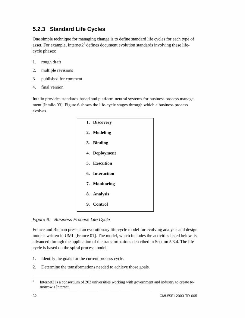
Intalio provides standards-based and platform-neutral systems for business process manage-ment [Intalio 03]. Figure 6 shows the life-cycle stages through which a business process evolves.
1. Discovery
2. Modeling
3. Binding
4. Deployment
5. Execution
6. Interaction
7. Monitoring
8. Analysis
9. Control
Figure 6: Business Process Life Cycle
France and Bieman present an evolutionary life-cycle model for evolving analysis and design models written in UML [France 01]. The model, which includes the activities listed below, is advanced through the application of the transformations described in Section 5.3.4. The life cycle is based on the spiral process model.
1. Identify the goals for the current process cycle.
2. Determine the transformations needed to achieve those goals.
5 Internet2 is a consortium of 202 universities working with government and industry to create to-
morrow’s Internet.

CMU/SEI-2003-TR-005 33
3. Apply the transformations.
4. Evaluate the resulting model against the goals.
These examples illustrate that this type of definition aids in the management of evolution by providing a benchmark against which evolutionary changes can be compared. The life cycle defines valid next steps for an asset. During the change impact analysis, the anticipated changes are compared to the life cycle to determine whether the changes are acceptable.
5.2.4 Technology Forecasting
Technology forecasting predicts the directions the evolution of assets should take. The “Technology Forecasting” practice area describes the following steps [Clements 02c]:
1. Perform research to isolate promising technologies.
2. Validate the technologies through modeling or simulation.
3. Analyze and quantify the benefits for both developers and customers.
4. Conduct pilot tests.
5. Integrate the new technology with existing assets and then test it.
6. Provide training.
From the technology forecast, a plan is developed for introducing selected technologies into future products. This plan might manifest as new requirements in the products developed af-ter a certain point in time or in a particular price range. Or it might manifest transparently to the user as existing components are replaced with new ones. The plan identifies assets that must be developed or renovated, and coordinates the direction of change for the affected por-tions of the product line.
5.3 Evolution Transformations
Evolution transformations move assets from one form to another. Because they do so in a predictable direction, they can be chosen to achieve specific objectives. Transformations are useful because they are predictable and maintain consistency among modified assets. Al-though these transformations all apply to a product line’s software assets, many of them can be applied to non-software assets as well.
Transformations are inherently reactive; they are applied to existing assets to change their attributes.

34 CMU/SEI-2003-TR-005
5.3.1 Refactoring
Refactoring is a technique by which the current module structure of a set of software assets is changed, usually by reallocating and regrouping behavior found in other structures. The modified structure is based on experience with the existing structure and is intended to im-prove the set of assets based on some criteria. Opdyke provides a design-refactoring tech-nique that ensures the internal consistency of assets in the new design [Opdyke 92].
Tichelaar and colleagues provide an experimental refactoring technique for building systems using stable components and quickly written scripts to glue the components together [Tiche-laar 00]. Although experimental, the technique points out the usefulness of separating com-ponents from the mechanisms that bind them. In this approach to refactoring, components are atomic, and refactoring is limited to rearranging existing components or developing new ones.
5.3.2 Reconfiguration
An existing asset can be transformed by changing the objects that implement it. This recon-figuration involves taking advantage of the assets that were designed after the original asset was. Large portions of entire products can be reconfigured after several versions have been released. This is one way to meet new requirements that call for a behavior that is both differ-ent from and related to the old one.
5.3.3 Customization
Customization transforms existing assets to satisfy new requirements that are related to exist-ing ones. Language mechanisms, such as inheritance and wrapping, provide specific tools for customization. For example, Figure 7 illustrates in UML class B being created from class A using inheritance. In this example, B represents a specialized case of A. Behaviors from A, such as Method1, might be overridden to provide customized versions of that general behav-ior in class B. New behaviors such as Method3 can be added, although typically they are lim-ited to supporting existing behaviors.

CMU/SEI-2003-TR-005 35
B Method1() Method 3()
A Method1() Method 2()
Figure 7: Inheritance
Wrapping is a more general form of customization. While object B might be a specialization of A, it might also be designed to ensure compatibility with some other interface. Different implementations might be introduced, such as using object C rather than object A to provide Method2. Wrapping can be used to change the signature of methods as illustrated in Figure 8.
This evolution transformation provides a localized way of supporting new functional and nonfunctional attributes.
Method1(int x, float y)
Method1(5, y)
A
B
Method2(int x, float y) C
Method2(x,y)
Method2(x,y)
Figure 8: Wrapping
5.3.4 Model Transformations
Analysis and design information is often captured in a model that represents the intended sys-tem. These models evolve over time as more detail is added, defects are repaired, and addi-tional types of information are added to them. For most product line systems, the models rep-resent sufficient investment that they are under configuration control. The successive versions

36 CMU/SEI-2003-TR-005
of a model have relationships with earlier versions. The changes in a model can be thought of as the result of a series of transformations that take one model as input and produce another model as output. The transformations can be used to document the evolution of the model to aid in understanding its current status or to identify places where defects were injected.
Consider models developed using UML [OMG 01]. A high-level design model will, at some point in the development process, be refined to include more detail. The refinement transfor-mation includes adding new classes to class diagrams as needed to implement the high-level domain classes. The transformation also adds other information to the existing model and produces a “refined” model. For example, one popular system design technique begins with a model of domain analysis information and merges it with application analysis information to produce a complete analysis model. That model evolves to include design information and results in a detailed design model. The system design technique can be explained as a series of transformations that evolve a final detailed design model from high-level models.
France and Bieman discuss a set of transformations for explaining the evolution of design models [France 01]. Their list includes the transformations we already discussed plus
������ , ���� , and ����� (shown here as UML stereotypes). Those transfor-mations, which are used as relationships between two or more UML models, are variants of the UML standard abstraction relationship. In particular, ������ and ���� denote a temporal sequence of models that gives one type of direction for the evolution. A
������ relationship exists between a design model and the code that implements it.
5.3.5 Change Impact Analysis
Change impact analysis provides a means of predicting which assets will be affected by a specific change [Bohner 96]. This analysis involves
• conducting a traceability analysis to identify impacted places
• identifying the interactions affected by the change
• evaluating the effect of changes on assumptions
• identifying new constraints
• identifying regression tests
Change impact analysis helps determine the effect that a proposed change will have on the core assets before the change is made. Using that analysis, the analyst can determine whether the benefit from the change is worth the effort required to make it. The analysis can also con-sider possible asset degradation caused by the change. The results from the impact analysis can point to alternative, perhaps more attractive, approaches to achieving the desired goal.

CMU/SEI-2003-TR-005 37
Change impact analysis begins by identifying a root asset to which the initial change is made. Next, the relationships between that asset and others are traced. Then, each related asset is examined to determine if it will be affected by the proposed change, and if so, what, if any, changes must be made to it. The effort to make additional changes is added to the total effort needed, resulting in an estimated scope and cost of the change.
For example, consider conducting an impact analysis of a change that is made to interface A to provide a new service. The impact of this change is traced to other interfaces that depend on interface A. Those interfaces might specify parameters using interface A as the type identi-fier, or they might be derived from interface A. The change is also traced to all the compo-nents that implement interface A and its derived interfaces. Those components will require some modification as well. The result of this analysis would be a decision to derive a new interface, containing the added service, from interface A—the original target of the modifica-tion. Deriving a new interface would eliminate the need to implement the service in every interface derived from the target one.
5.3.6 Incremental Consistency Analysis
The models used to design products evolve over time. In fact, many design methods are itera-tive in nature, ensuring that evolution will occur. Each iteration results in modifications—additions, changes, and deletions—to the model. The modifications must remain consistent with the unaffected portions of the model.
A number of consistency criteria exist for state models and for models developed using UML [Kuzniarz 02]. At a simple level, some UML modeling tools perform these checks automati-cally. More complete criteria must be applied manually, so it quickly becomes impractical for realistic models.
Engels and colleagues present an experimental technique for checking the consistency of models incrementally [Engels 02]. As additions are made to a model, the consistency is only checked locally. The cost of this local checking is that changes to the model must be accom-plished using a small set of consistency-preserving transformations.
5.4 Automated Techniques
Van Gurp and Bosch [van Gurp 01] analyzed two case studies concerning object-oriented frameworks and made recommendations to overcome problems with the evolution of those frameworks. The first was to automate the frameworks’ configuration for use in a specific product. The second recommendation was to automate the documentation. In this section, we consider both of these areas plus the tools needed for detailed analysis.

38 CMU/SEI-2003-TR-005
5.4.1 Change Management
All assets evolve. This evolution is the result of many changes that happen over time. Manag-ing these changes in a product line is particularly difficult because of the many relationships among assets. A product line organization must have an effective plan for managing change to handle the complexities of relationships among assets. In this section, we consider the use of configuration management and version control techniques for product line core assets and products.
Version control is the ability to track changes in individual artifacts. A system that handles version control typically allows a user to access an artifact as it was at various points in time before certain modifications. These systems support experimentation by supporting concur-rent definitions of a single artifact. If the experiment proves successful, the version control software provides a means for merging the “branched” definition into the main body of work from which the branch was created.
A configuration is the set of artifacts that comprise a unit of interest such as a product or an asset. A software application configuration contains all required software modules, data such as properties, resources such as sounds or pictures, and documentation such as help files. As members of the configuration are modified and new versions are released, a new version of the configuration is created. Configuration management software usually includes the ability to create versions of individual elements of the configuration.
Figure 9 shows a sequence of configuration versions from version 1 to 1.1 to 1.2 as new items are added to the configuration and as new versions of existing elements are created. Component A is modified and a new version—A2—is created in configuration 1.2. This is the usual progression during product development. Software product lines add dimensions to the configuration picture. For example, moving from configuration 1.1 to configuration 2 is due to the creation of a new variant of component A—A1. A new form of dependency is in-troduced between these two elements.

CMU/SEI-2003-TR-005 39
architecture
time
requirements
architecture
requirements
change
component A
change
architecture
requirements, version 2
component A1
component B
architecture
requirements
component A2
Variations of A
change
Configuration 1 Configuration 1.1 Configuration 1.2
Configuration 2
Figure 9: Dimensions of Change
Configuration management techniques and tools are used to manage the dependencies that result from change. They support the change process by capturing the state of product evolu-tion at significant points. Configuration management controls change but does not mitigate the effects of continuing change on the quality of the artifacts. That is left to the appropriate asset design and development techniques.
An effective configuration management plan is essential to a successful product line. The plan must describe how the organization will provide three things:
1. concurrent development of related assets
2. use of an asset in multiple products
3. multiple versions of multiple variants of both assets and products
Traditional configuration management tools are designed to handle items (1) and (2). How-ever, as Krueger points out, a product line organization faces a more complicated situation—the dependencies among products [Krueger 02]. Over time, there will be many versions of a product—the situation for which configuration management was designed. In addition, there will be multiple products that must be managed simultaneously—another problem that can be solved using traditional configuration management systems. The difficulty arises from the fact that those multiple products are not independent as they normally would be in “stove-pipe” implementations. They share a large number of common assets, whose lives and health must be managed along with the products they support.

40 CMU/SEI-2003-TR-005
architecture
time
requirements
architecture
requirements
change
component A
change
architecture
requirements, version 2
component A1
component B
architecture
requirements
component A2
Variations of A
change
Configuration 1 Configuration 1.1 Configuration 1.2
Configuration 2
architecture
requirements, version 2
component
Configuration 2.1
component A3
?
? ?
Figure 10: Implications of Evolution
The configuration management plan for a product line must address all three items above. In particular, it must address (3), which is not supported by traditional configuration manage-ment tools. In Figure 10, a new version of component A is created in configuration 2.1. What is the relationship of this version to A, A1, and A2? When the basic asset component A is modified, should the variant A1 also be modified? Only if the modification is a bug fix? Al-ways?
The configuration management plan presents the product line’s strategy for managing these dependencies and for answering the questions about when to propagate change. The plan should describe how configurations of any asset might be handled. For example, the architec-ture documentation for assets is stored in numerous files. The system should allow a configu-ration for the architecture just as it does for a product.
Consider the wireless device example. Each product is the marriage of a hardware device and software. The software for each wireless device is defined as a configuration of required de-vice drivers, transmission and reception protocols, and a large number of independent appli-cations such as phonebooks and games. Each application will have many versions during construction including a release version and a number of post-release versions as mainte-nance proceeds.
The difficulty with traditional configuration management software arises when several wire-less devices share several assets such as protocol state machines and operating-system inter-

CMU/SEI-2003-TR-005 41
faces. Assume that two variants of the state machine component are created for some of the products in the product line. A defect is discovered in the basic asset and corrected. This fix must be propagated to the variants. The configuration management strategy of the product line must provide a means of locating all the affected components.
Two strategies that are possible here include the automatic generation of the variants from the basic asset and a database approach. Consider a situation in which a base asset is modified to produce variants by weaving an aspect into the base asset. The variants should not be stored as finished products. They should be created each time they are needed, by taking the current version of the base asset and the current version of the aspect, and weaving them together.
The database approach stores completed variants and a set of relations among the assets that the configuration management tool is not capable of managing. When a defect is found in the base asset, the database provides all the variants that depend on that asset. Changes can then be applied to each of those variants.
5.4.2 Documentation
Automating documentation ensures that the asset and its documentation are consistent. Typi-cally, this is done by requiring the use of specific tags embedded in the asset. For example, a number of program documentation tools (e.g., javadoc) create documents from special com-ments embedded in the software.
A documentation tool can be combined with a defined life cycle to provide a complete solu-tion. Each stage in the asset’s life cycle has a corresponding content specified for the docu-mentation. Standard XML formats for UML models and other representations have enabled the use of general-purpose modeling tools to handle a range of documentation responsibili-ties. New DTDs can be derived as specializations of existing ones, thus supporting evolution of the XML formats in parallel with the specialization of model elements.
5.4.3 Program Analysis Tools
The code base for a product line is typically very large relative to the size of the products be-cause it contains all the code used in all the products, not just one. Although the code base might be in the form of source code, it will almost always contain some amount of acquired assets for which source code is not available. Automated tools are needed for managing the code base. Ryder and Frank describe a technique for automating change impact analysis of object-oriented code; however, it requires source code [Ryder 01].

42 CMU/SEI-2003-TR-005
Tools designed specifically to manage evolution are based on the conceptual tools discussed in Section 5.1. Tools are available to support the software developer in refactoring a design and then automatically refactoring the corresponding code.

CMU/SEI-2003-TR-005 43
6 Summary
All the assets of a product line organization will evolve over time, and there are many initiat-ing forces:
• Users want more features or the latest technology for existing features.
• People learn new skills or improve the ones they already possess.
• New standards are developed and existing standards are upgraded.
• Vendors phase out products and offer new ones.
The basic techniques for managing product evolution are anticipation and direction. Planning and analyzing market trends and technology changes allow the product line organization to anticipate changes in its products. Techniques such as change impact analysis allow the core asset team to make decisions about which changes to allow.
By anticipating evolution, the organization can set the direction of some evolutionary forces to align with its strategic objectives. Evolving the production process for the product to be fully automated is useful if the corporate strategy is to introduce a large number of small variations to offer customized products to retailers.
The direction of evolution provides a means for managing the consistency of assets. When changes are anticipated, the direction of evolution is defined in terms of the desired end result and the starting point, and then it’s applied to each affected asset. Once a set of assets has an associated evolution direction, each asset can be modified independently with confidence that consistency will be maintained.
Risks resulting from evolution relate primarily to losing the consistency, completeness, and correctness of the asset base. These risks increase with the size of the asset base and the com-plexity of the relations among the assets in it. Anticipation and control of evolution reduces the likelihood of the risks becoming a problem. Applying evolution transformations reduces the impact that those problems can have on the asset base.
Not all evolution is totally controllable, but it can be influenced. Vendors make independent decisions but listen to their customers and user groups. Standards bodies make democratic group decisions, but those who participate in the standards-producing activity influence its outcome.

44 CMU/SEI-2003-TR-005
Successful product line organizations use practice areas such as “Market Analysis,” “Tech-nology Forecasting,” and “Configuration Management” as tools to mitigate the risks of evo-lution. By anticipating even uncontrollable evolution, the organization can design processes and assets that minimize the impact of change on the product line.

CMU/SEI-2003-TR-005 45
Bibliography
URLs valid as of the publication date of this document.
[Ajila 95] Ajila, Samuel A. “Software Maintenance: An Approach to Im-pact Analysis of Objects Change.” International Journal of Software Practice and Experience 25, 10 (October 1995): 1155-1181.
[Ajila 99] Ajila, Samuel A. “Dealing with Impact Analysis of Objects Change in a Distributed Team-Based Software Development: Basic Concepts and Perspectives,” 531-536. Proceedings of the 5th International Conference on Information Systems, Analysis and Synthesis, Vol. 2. Orlando, Florida, July 31–August 1, 1999. Orlando, FL: International Institute of Informatics and Sys-temics, 1999.
[Ajila 02] Ajila, Samuel A. “Change Management: Modeling Software Product Lines Evolution,” 492-497. Proceedings of the 6th World Multiconference on Systemics, Cybernetics, and Informatics. Orlando, Florida, July 14–18, 2002. Orlando, FL: International Institute of Informatics and Systemics, 2002.
[Bass 03] Bass, Len; Clements, Paul; & Kazman, Rick. Software Architec-ture in Practice, 2nd edition. Reading, MA: Addison-Wesley, 2003.
[Bohner 96] Bohner, S. A. & Arnold, R. S. Software Change Impact Analysis. Los Alamitos, CA: IEEE Computer Society Press, 1996.

46 CMU/SEI-2003-TR-005
[Bosch 99] Bosch, Jan. “Evolution and Composition of Reusable Assets in Product-Line Architectures: A Case Study,” 321-339. Proceed-ings of WICSA1: First Working IFIP Conference on Software Architecture. San Antonio, Texas, February 22-24, 1999. Boston, MA: Kluwer Academic Publishers, 1999.
[Bosch 00] Bosch, Jan. Design & Use of Software Architectures: Adopting and Evolving a Product-Line Approach. Reading, MA: Addison-Wesley, 2000.
[Bosch 02] Bosch, Jan. “Maturity and Evolution in Software Product Lines: Approaches, Artefacts and Organization,” 257-271. Proceedings of the Second Software Product Line Conference (SPLC2) (LNCS 2370). San Diego, California, August 19–22, 2002. New York, NY: Springer-Verlag, 2002.
[Chapin 01] Chapin, Ned; Hale, Joanne E.; Khan, Khaled; Ramil, Juan F., & Tan, Wui-Gee. “Types of Software Evolution and Software Maintenance.” Journal of Software Maintenance and Evolution Research and Practice 13, 1 (January/February 2001): 3-30.
[Chidamber 94] Chidamber, S. R. & Kemerer, C. F. “A Metrics Suite for Object-Oriented Design.” IEEE Transactions on Software Engineering 20, 6 (June 1994): 476-493.
[Clements 02a] Clements, Paul & Northrop, Linda. Software Product Lines: Practices and Patterns. Boston, MA: Addison-Wesley, 2002.
[Clements 02b] Clements, Paul; Kazman, Rick; & Klein, Mark. Evaluating Software Architectures: Methods and Case Studies. Boston, MA: Addison-Wesley, 2002.
[Clements 02c] Clements, Paul & Northrop, Linda. A Framework for Software Product Line Practice, V4.1. <http://www.sei.cmu.edu/plp /framework.html> (2002).

CMU/SEI-2003-TR-005 47
[Clements 02d] Clements, Paul & Northrop, Linda. Salion, Inc.: A Software Product Line Case Study (CMU/SEI-2002-TR-038, ADA412311). Pittsburgh, PA: Software Engineering Institute, Carnegie Mellon University, 2002. <http://www.sei.cmu.edu/publications/documents/02.reports /02tr038.html>.
[Coplien 96] Coplien, James O. Software Patterns. New York, NY: SIG Books, 1996.
[Demeyer 01] Demeyer, Serge; Mens, Tom; & Wemelinger, Michel. “Towards a Software Evolution Benchmark,” 174-177. Proceedings of the International Workshop on Principles of Software Evolution. Vienna, Austria, September 10-11, 2001. New York, NY: ACM Press, 2001.
[Eclipse 03] Eclipse.org. <http://www.eclipse.org> (June 2003).
[Engels 02] Engels, Gregor; Heckel, Reiko; Kuster, Jochen M.; & Gro-enewegen, Luuk. “Consistency-Preserving Model Evolution Through Transformations,” 212–226. Proceedings of UML 2002, Unified Modeling Language. Model Engineering, Concepts, and Tools. 5th International Conference (LNCS 2460). Dresden, Germany, September 30–October 4, 2002. New York, NY: Springer-Verlag, 2002.
[France 01] France, Robert & Bieman, James M. “Multi-View Software Evolution: A UML-Based Framework for Evolving Object-Oriented Software,” 386-395. Proceedings of the IEEE Interna-tional Conference on Software Maintenance (ICSM 2001). Flor-ence, Italy, November 7-9, 2001. Los Alamitos, CA: IEEE Com-puter Society, 2001.
[Intalio 03] Intalio, Inc. <http://www.intalio.com/products/index.html> (June 2003).

48 CMU/SEI-2003-TR-005
[Kniesel 02] Kniesel, Gunter; Noppen, Joost; Mens, Tom; & Buckley, Jim. “Unanticipated Software Evolution,” 92-106. Proceedings of the First International Workshop on Unanticipated Software Evolu-tion. Malaga, Spain, June 11, 2002. New York, NY: Springer-Verlag, 2002. <http://link.springer.de/link/service/series/0558 /papers/2548/25480092.pdf>.
[Krueger 02] Krueger, Charles W. “Variation Management in Software Pro-duction Lines, 37-48. Proceedings of the Second International Conference on Software Product Lines (SPLC2) (LNCS 2370). San Diego, California, August 19–22, 2002. New York, NY: Springer-Verlag, 2002.
[Kuzniarz 02] Kuzniarz, L.; Reggio, G.; Sourrouille, J. L.; & Huzar, Z. UML 2002-Model Engineering, Concepts, and Tools: Workshop on Consistency Problems in UML-Based Software Development: Workshop Materials (Research Report 2002: 06). Karlskrona, Sweden: Blekinge Institute of Technology, 2002. <http://www.ipd.bth.se/uml2002/RR-2002-06.pdf>.
[Lehman 98] Lehman, M. M.; Perry, D. E.; & Ramil, J. F. “On Evidence Sup-porting the FEAST Hypothesis and the Laws of Software Evolu-tion,” 84-88. Proceedings of the Fifth International Software Metrics Symposium (Metrics98). Bethesda, Maryland, Novem-ber 20-21, 1998. Los Alamitos, CA: IEEE Computer Society, 1998.
[Martin 03] Martin, Robert C. Agile Software Development. Upper Saddle River, NJ: Prentice Hall, 2003.
[Mens 00] Mens, Tom & D’Hondt, Theo. “Automating Support for Soft-ware Evolution in UML.” Automated Software Engineering 7, 1 (March 2000): 39-59.
[Mens 01] Mens, Tom & Demeyer, S. “Future Trends in Software Evolu-tion Metrics,” 83-86. Proceedings of the 4th International Work-shop on Principles of Software Evolution. Vienna, Austria, Sep-tember 10-11, 2001. New York, NY: ACM Press, 2001.

CMU/SEI-2003-TR-005 49
[Merriam-Webster 93] Merriam-Webster, Inc. Merriam-Webster’s Collegiate Diction-ary, Tenth Edition. Springfield, MA: Merriam-Webster, Inc., 1993.
[OMG 01] Object Management Group. OMG Unified Modeling Language Specification, V1.4. Needham, MA: Object Management Group, 2001. <http://www.omg.org/docs/formal/01-09-67.pdf>.
[Opdyke 92] Opdyke, W. F. “Refactoring Object-Oriented Frameworks.” PhD diss., University of Illinois, 1992.
[Porter 98] Porter, Michael E. Competitive Strategy: Techniques for Analyz-ing Industries and Competitors. New York, NY: Free Press, 1998.
[Ryder 01] Ryder, Barbara G. & Tip, Frank. “Change Impact Analysis for Object-Oriented Programs,” 46-53. Proceedings of the 2001 ACM SIGPLAN-SIGSOFT Workshop on Program Analysis for Software Tools and Engineering (PASTE’01). Snowbird, Utah, June 18-19, 2001. New York, NY: ACM Press, 2001.
[Simon 01] Simon, F.; Steinbruckner, F.; & Lewerentz, C. “Metrics-Based Refactoring,” 30-38. Proceedings of the Fifth European Confer-ence on Software Maintenance and Reengineering. Lisbon, Por-tugal, March 14-16, 2001. Los Alamitos, CA: IEEE Computer Society, 2001.
[Sun 03] Sun Microsystems, Inc. Java 2Platform, Standard Edition (J2SE). <http://java.sun.com/j2se/javadoc/index.html> (June 2003).
[Svahnberg 99] Svahnberg, Mikael & Bosch, Jan. “Evolution in Software Prod-uct Lines: Two Cases.” Journal of Software Maintenance 11, 6 (November/December 1999): 391-422.
[Svetinovic 01] Svetinovic, Davor & Godfrey, Michael. Attribute-Based Soft-ware Evolution: Patterns and Product Line Forecasting. <http://plg.uwaterloo.ca/~migod/papers/> (2001).

50 CMU/SEI-2003-TR-005
[Tichelaar 00] Tichelaar, S.; Ducasse, S.; Demeyer, S.; & Nierstrasz, O. “A Meta-Model for Language-Independent Refactoring,” 154-164. Proceedings of the International Symposium on Principles of Software Evolution (ISPSE 2000). Kanazawa, Japan, November 1-2, 2000. Los Alamitos, CA: IEEE Computer Society, 2000.
[Tokuda 01] Tokuda, Lance & Batory, Don. “Evolving Object-Oriented De-signs with Refactorings.” Automated Software Engineering 8, 1 (January 2001): 89-120.
[van Gurp 01] van Gurp, Jiles & Bosch, Jan. “Design, Implementation, and Evolution of Object-Oriented Frameworks: Concepts and Guide-lines.” Software—Practice and Experience 31, 3 (March 2001): 277–300.

REPORT DOCUMENTATION PAGE Form Approved OMB No. 0704-0188
Public reporting burden for this collection of information is estimated to average 1 hour per response, including the time for reviewing instructions, searching existing data sources, gathering and maintaining the data needed, and completing and reviewing the collection of information. Send comments regarding this burden estimate or any other aspect of this collection of information, including suggestions for reducing this burden, to Washington Headquarters Services, Directorate for information Operations and Reports, 1215 Jefferson Davis Highway, Suite 1204, Arlington, VA 22202-4302, and to the Office of Management and Budget, Paperwork Reduction Project (0704-0188), Washington, DC 20503.
1. AGENCY USE ONLY
(Leave Blank)
2. REPORT DATE
June 2003
3. REPORT TYPE AND DATES COVERED
Final 4. TITLE AND SUBTITLE
The Evolution of Product Line Assets
5. FUNDING NUMBERS
F19628-00-C-0003 6. AUTHOR(S)
John D. McGregor 7. PERFORMING ORGANIZATION NAME(S) AND ADDRESS(ES)
Software Engineering Institute Carnegie Mellon University Pittsburgh, PA 15213
8. PERFORMING ORGANIZATION REPORT NUMBER
CMU/SEI-2003-TR-005
9. SPONSORING/MONITORING AGENCY NAME(S) AND ADDRESS(ES)
HQ ESC/XPK 5 Eglin Street Hanscom AFB, MA 01731-2116
10. SPONSORING/MONITORING AGENCY REPORT NUMBER
ESC-TR-2003-005
11. SUPPLEMENTARY NOTES
12A DISTRIBUTION/AVAILABILITY STATEMENT
Unclassified/Unlimited, DTIC, NTIS
12B DISTRIBUTION CODE
13. ABSTRACT (MAXIMUM 200 WORDS)
Change is a natural, although not always welcome, part of product line development. The changes may be initiated to correct, improve, or extend assets or products. Since no asset is independent of all other assets, changes to one asset often require corresponding changes in other assets. And changes to assets propagate to affect all the products using those assets. Many of the practices of a successful product line initiate, man-age, or consume these changes. Both conceptual techniques and software tools are available to assist in the management of these changes.
The focus of this technical report is how evolutionary changes affect the various types of assets in a software product line. Change can be anticipated and managed, or it can be unanticipated and potentially disruptive. This technical report defines a few basic evolution concepts and then discusses those product line practices that initiate, anticipate, control, and direct the evolution. Conceptual and automated techniques that support these practices are also presented.
14. SUBJECT TERMS
software evolution, evolution, product lines, asset evolution 62
16. PRICE CODE
17. SECURITY CLASSIFICATION
OF REPORT
Unclassified
18. SECURITY CLASSIFICATION OF THIS PAGE
Unclassified
19. SECURITY CLASSIFICATION OF ABSTRACT
Unclassified
20. LIMITATION OF ABSTRACT
UL
NSN 7540-01-280-5500 Standard Form 298 (Rev. 2-89) Prescribed by ANSI Std. Z39-18 298-102