the fasterblaster cleaning system-3
TRANSCRIPT
The FasterBlaster Cleaning System
Operation, Maintenance & Safety Manual
RBW Enterprises, Inc.169 Hillwood CircleNewnan, GA 30263
Phone: (770) 251-8989Mobile: (770) 757-4944
Updated 12/1/2010

2
CAUTIONThe blast machine generates heat. The dust collectorcreates the vacuum to remove dust, ventilate and coolthe machine. If the dust collector filters get plugged, thevacuum will be blocked, the machine will heat up anddust will build up in the machine. Some paint dust with highVOC content can ignite and cause a fire in the dust collector.The filters MUST be pulsed on a continuous basis. Make surethat these precautions are followed.
1) Make sure that the compressed air hose is attached to thedust collector pulse system and that the air is on beforestarting the machine.
2) Check the Magnahelix Gauge- Make sure that the needleis on 1 or below. If the needle gets up to 2, stop and pulsedown the filters for 10 minutes with the dust collector fan off( leaving the power switch on). If the gauge doesn’t drop,replace the filters.
3) Filter replacements must be fire retardant type DonaldsonPt # P527079-016-002.
Compressed Air Be Connectedand ON before operatingthe machine. If filters areallowed to plug the machinecan over heat.
Must

3
Six steps to keep your machine in top condition and running properly
1. Use only S-330 or S-390 steel shot. If an angular profile is required, use GS-25 orGP-25 grit. Never use: small grit (G-40), hard grit (GH,GM or GL), or shot larger
than S-390. Never use recycled shot or grit. The use of abrasives, other than the
recommendations above, will result in high wear and will damage the Blast Wheelcomponents, the Liners, the Blast Cabinet and the Blast Motor.
2. If the blast motor starts vibrating, the blast wheel assembly is probably out ofbalance due to wear or improper installation. Stop the machine and fix theproblem. The blast motor bearings and the aluminum bearing support housing willbe damaged if vibration is unchecked. Check the blades and impeller for wear ordamage and repair or replace as needed. Be sure to weigh each blade and toinstall blades of equal weight directly opposite one another to assure a balancedwheel assembly. Review page 19.
3. Remember that the most important factor for good cleaning, high production andminimal abrasive leakage is good vacuum. Eliminate vacuum leaks by keeping allconnections tight, all seals in good condition and all gaps filled with silicone. Checkfor leaks by running the dust collector fan without the blast wheels running. Listenand feel for air leaks around all connections and seals on the machine, the dustcollector and the exhaust hose connecting the two units. Tighten connections,replace worn seals and fill any and all gaps with silicone. Check the exhaust hosefor holes and damaged or collapsed areas. Check for a tight seal between the dustdrum and the dust collector. Make sure that the air supply is connected to the dustcollector filter cleaning system. Check the magnahelix guage on the dust collectorto make sure that the filters are not plugged. The magnahelix should read around 1or below. If readings of 2 or above is noted, stop the operation for 10 minutes, turnoff the dust collector fan and leave the power switch on so the filters will be pulsecleaned. After the pulse down, recheck the magnahelix guage.
4. Damaged blades, impellers and liners can cause distortion of the blast pattern andcan result in poor cleaning and abrasive leakage. Check the high wearcomponents often and repair or replace as needed. See pages 18-23 to identifythe wear components.
5. If any component becomes loose, makes unusual sounds, or malfunctions in anyway, do not continue operation. Stop the machine and fix the problem. If youare unsure how to fix the problem refer to this manual and / or call RBWEnterprises.
6. Follow all safety instructions in this manual, and all safety signs on the machine. Ifyou see a safety concern stop the operation and correct the problem or call RBWEnterprises.

4
Index
Hazardous Materials Safety Warning------------------------------5Hazardous Products Safety Warning------------------------------6Forward----------------------------------------------------------------------7System Description------------------------------------------------------8-9The FasterBlaster System (Pictorial)------------------------------ 10Operation Requirements-----------------------------------------------11Tools and Safety Equipment-----------------------------------------12Safety Instructions-------------------------------------------------------13-17Job Site Set-Up------------------------------------------------------------18FasterBlaster Parts Overview----------------------------------------19High Wear Replacement Parts---------------------------------------20Wear Part Repair & Replacement-----------------------------------20-22Main Seal Parts-----------------------------------------------------------23-24Connection Seals--------------------------------------------------------25Dust Collector Parts-----------------------------------------------------26Dust Collector Inspection & Maintenance-----------------------27Hoist System Parts-------------------------------------------------------28Hoist System Maintenance--------------------------------------------29-32Set-Up & Operation Instructions (Floors & Roofs)-----------33-43Set-Up & Operation Instructions (Vertical Walls)-------------44-62
Cone Roof Fixture Set-Up------- 44- 46Floating Roof Fixture Set-Up--- 47- 50C-Frame Fixture Set-Up---------- 51- 53
Main Panel Controls-----------------------------------------------------63-64Inside the Control Panel------------------------------------------------65-67Machine Panel Controls------------------------------------------------68Hand Held Remote Controls------------------------------------------66-67FasterBlaster Component & Material Check List--------------69Safety Labels--------------------------------------------------------------72-74Machine Break Down to Fit through Man Hole------------------75-77Re-Assembling the Machine Inside the tank----------------- --78-80Electrical Drawings------------------------------------------------------81-88Pipe Cleaning--------------------------------------------------------------89-91

5
Hazardous Materials Safety Warning
Some surfaces may contain or be coated with Hazardous Materials. Typicalexamples of hazardous materials include coatings, which may contain LEAD orother toxic materials, and surface construction, which may contain PetroleumProducts, Asbestos, Solvents, or other Harmful Chemicals.During the normal operation of shot blasting equipment, surface material isremoved and dust is created. When the surface material is contaminated, the dustmay contain hazardous material.It is probable that a small amount of dust will be released during the cleaningoperation. If this dust contains hazardous material, there is a danger that exposureto this dust may pose a health risk. Before using the FasterBlaster on any surface,the area must be inspected for possible contamination. Before beginning anyproject involving the removal of hazardous materials, it is the responsibility of thecontractor to insure that the work site and equipment to be used have beeninspected and the proper authorities have approved the proposed work. It is alsothe responsibility of the contractor to notify workers of any potential health risksand insure that workers are properly protected from exposure to hazardousmaterials. It is the contractor’s responsibility to keep the FasterBlaster CleaningSystem in top running condition to minimize dust leakage.
All Federal, State, Local and Plant Codes and Regulations must be followed whenremoving, handling, storing and disposing of hazardous materials.

6
Hazardous Products Safety Warning
The FasterBlaster Cleaning System is designed to clean horizontal and verticalsurfaces such as ship hulls, water tanks, oil tanks and bridges. It is the contractor'sresponsibility to verify the contents of the storage tank or ship hold being cleaned.Tanks or ship holds, which emit volatile fumes, should be emptied and thetank should be properly degassed before work proceeds.
The facility owner is responsible for making decisions as to what product fumesare considered volatile and the safety procedures to follow during the cleaningoperation. If the product is flammable, the Safety Department should test the fumeconcentration and issue a Hot Work Permit before work is started each day. Thisprocedure should be followed even though the product has been removed.
It is the responsibility of the facility owner to advise the contractor when product ispumped into or out of any tank in the area near the tank being cleaned. Alloperations should be shut down during the pumping process.
It is the responsibility of the contractor to review the above precautions with thefacility owner and to follow the safety procedures.

7
FORWARD
RBW Enterprises is pleased that you have selected The FasterBlaster Cleaning Systemfor your surface preparation requirements. This self-contained surface preparationmachine has been designed for abrasive blast cleaning of both horizontal and verticalsurfaces.
This manual has been prepared to assist the owner, his operators and maintenancepersonnel in understanding the system, in order to operated in a safe and efficientmanner. It is essential that all personnel responsible for the operation andmaintenance of the machine, study and understand this manual.
Before attempting to operate or service the system, personnel should thoroughlyfamiliarize themselves with each machine component and have a good understanding ofits operation.
Operation and maintenance personnel must obey all warnings and safetyprecautions posted on the machine and stated throughout this manual. Seriousinjury or severe equipment damage may result if the warnings and precautions arenot followed. No instructions, either written or verbal, can be totally effective withoutthe use of sound judgment and good work practices. Owners should provideappropriate training and monitoring to assure that operating personnel follow goodwork practices.
A periodic review of the safety standards, covered in this manual, should be mandatory forall personnel involved in the operation and maintenance of the equipment. If you have anysuggestions for improvements or additions to this manual, please call us. Changes, whichoccur after this manual is printed, will be made by distribution of revisions. The revisions,when received, should be inserted in the manual in accordance with instructions, which willbe forwarded with them. The owner must advise his operators and maintenance personnelof all revisions.
This Operation, Maintenance, and Safety Manual should remain with the machine atall times and should be accessible to the operator for study and review.
This equipment should not be leased or loaned out to other contractors withoutproviding a trained operator and the Operation, Maintenance, and Safety Manual.
No alterations should be made to the equipment without the written approval ofRBW Enterprises. Unauthorized changes could affect or negate safety systems thatare built into the equipment. Unauthorized changes can also adversely affect theefficiency of operation and create safety hazards.
Receipt of Machine-Examine the shipment carefully for possible damage in transit. Ifdamage is noted, notify the transportation carrier immediately and advise RBWEnterprises.If you have any questions or problems in regard to the operation or capabilities of thisequipment, please contact:
RBW Enterprises, Inc.169 Hillwood CircleNewnan, GA 30263
Phone/ Fax (770) 251-8989 –Cell (770) 757-4944

8
System Description(See Photos-page 8: The FasterBlaster System )
The FasterBlaster is the only blast cleaning machines that can clean both horizontal andvertical surfaces, such as floors, roofs, side walls of tanks and other structures.. TheFasterBlaster can be converted to either the vertical or horizontal cleaning mode in less than 1hour and can be quickly disassembled to fit through a 24” diameter opening for the internalcleaning of tanks. Due to the compact design, the unit can clean close to obstructions andbottom sole plates of tanks. This unit can also be used for high speed etching of concretesurfaces. The large 16” diameter centrifugal blast wheels are powered by 30 hp-3600 rpmmotors. The unit provides a 34” wide blast pattern. Production rates can reach 2000 sq. ft./ hr.on steel surfaces. Concrete surfaces are processed at much higher rates.In the vertical mode, a Hoist System, mounted on a powered Fixture at the top of thestructure being cleaned, raises and lowers the Blast Module as the module and fixturetraverse horizontally. The system can provide Spot, Sweep, Commercial, Near-White orWhite Metal finishes. The operator controls the machine movement, hoist operation, and blastfunctions from the hand-held Wireless Remote Control. The abrasive media is contained,circulated, and cleaned within the Blast Module. A vacuum hose automatically deposits thepaint and dust in a 55 gallon drum, located below the portable KleanVac Dust Collector onthe ground. When the drum is full, it is easily removed and capped for disposal. The totaldisposable waste, after cleaning a typical 100’ diameter tank, would be 2 to 3 drums,depending on paint thickness. This cleaning system eliminates dust emissions and operatorsafety concerns associated with other cleaning methods. The high cost of blasting, clean-upand disposal is reduced to only a few cents per square foot.
General Component Description
Blast ModuleThe Blast Module contains two (2) 30 H.P. centrifugal abrasive throwing wheels, an abrasivecirculation system and an air-wash separator. The separator cleans the abrasive and removes thepaint and dust. The module also incorporates a flexible seal assembly that assures dust freecontact with the surface. The Blast Module is protected internally with manganese steel andeasily replaceable hard-faced liners. The module is driven along the surface by two variablespeed DC gear motors, which rotates two traction tires. All operation functions are controlled bya wireless remote control.
Dust Collector CartThe lightweight Dust Collector Cart is usually positioned on the ground and in the center of thecleaning path. The operator can pull the unit around the tank as the cleaning progresses. The unithouses the main electrical control panel which feeds power to the FasterBlaster module, winchand fixture drive. The dust collector incorporates cartridge filters and an automatic pulse typecleaning system. A 2 CFM, 80 PSI air source is required to provide air for pulse cleaning thefilters. An air cooling system and water filter is provided to remove water from thecompressed air.

9
Winch SystemThe Winch System includes two cable drums and a drive arrangement which raisesand lowers the FasterBlaster Module assembly. The cable drums are grooved toassure proper tracking of the cable. Two (2) one hundred and twenty five foot (125')cables are provided. The winch system operates at variable speeds from 1 to 20 ft.per minute. The winch assembly is mounted to a driven support fixture, which pivotsfrom the center of the tank and moves horizontally around the tank.
Additional Items Supplied with EquipmentAll electrical wiring between the control panel and the machine components (100')Air line between the control panel and the machine components (100')Power Cable from power source to control panel (200')Vacuum Duct from dust collector to Blast Module ( 100' )Field Training (Operation, Safety, Maintenance)Operation, Maintenance and Safety Manual
FixturesOur Tank Fixtures include component parts which bolt together to make equipmentsupports for cone roof and floating roof tanks. The floating roof fixture rides on thewind girder and is adjustable to cover the majority of girder configurations. Fixturesare also available for internal cleaning. Most of the fixture components andfabrications are made of aluminum to minimize weight. The fixtures are powered andare operated from the hand held remote control on the ground (See TheFasterBlaster System- (page 8) for various fixtures).

10
Vertical Cleaning Mode
Powered Fixture0 to 30’/Min. Travel Speed
Hoist System1’ to 20’/ Min. Travel Speed
Hoist Cables (125’)
Blast Module(2) 30 HP Blast Wheels34” Wide Blast Pattern
Vacuum Hose (100’)
KleanVac Dust Collector9 Torit Cartridge FiltersAutomatic Air Pulse SystemAir Dryer SystemBlast System Control PanelDeposits Paint and Dust into 55 Gal.drums
Weights & Measures•Blast Module - 1900#
(26” wide x 48” long x 45” tall)
Hoist System - 600#(67” long x 36” deep x 18” high)
Dust Collector - 1200#(45” wide x 67” long x 80” high)
Electrical Requirements
460 v. / 60 hz. / 3 phase100 amp. - Total Running Load
Cone Roof Tank
Floating Roof TankInternal Cleaning
Ship Fixture
Dome Roof Tank
Hand Held Remote ControlOperates all FunctionsWireless Operation
Floating RoofTankExternal Cleaning
Horizontal Cleaning Mode
Tank Fixtures
The FasterBlaster System
11
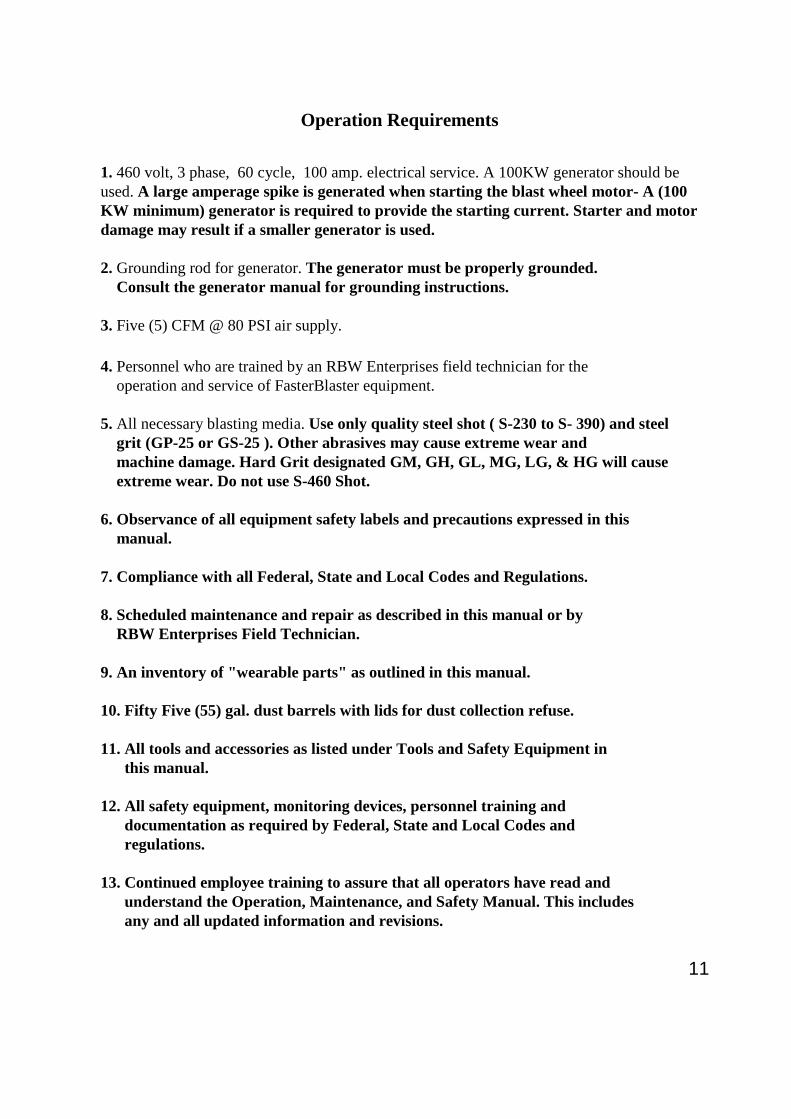
Operation Requirements
1. 460 volt, 3 phase, 60 cycle, 100 amp. electrical service. A 100KW generator should beused. A large amperage spike is generated when starting the blast wheel motor- A (100KW minimum) generator is required to provide the starting current. Starter and motordamage may result if a smaller generator is used.
2. Grounding rod for generator. The generator must be properly grounded.Consult the generator manual for grounding instructions.
3. Five (5) CFM @ 80 PSI air supply.
4. Personnel who are trained by an RBW Enterprises field technician for theoperation and service of FasterBlaster equipment.
5. All necessary blasting media. Use only quality steel shot ( S-230 to S- 390) and steelgrit (GP-25 or GS-25 ). Other abrasives may cause extreme wear andmachine damage. Hard Grit designated GM, GH, GL, MG, LG, & HG will causeextreme wear. Do not use S-460 Shot.
6. Observance of all equipment safety labels and precautions expressed in thismanual.
7. Compliance with all Federal, State and Local Codes and Regulations.
8. Scheduled maintenance and repair as described in this manual or byRBW Enterprises Field Technician.
9. An inventory of "wearable parts" as outlined in this manual.
10. Fifty Five (55) gal. dust barrels with lids for dust collection refuse.
11. All tools and accessories as listed under Tools and Safety Equipment inthis manual.
12. All safety equipment, monitoring devices, personnel training anddocumentation as required by Federal, State and Local Codes andregulations.
13. Continued employee training to assure that all operators have read andunderstand the Operation, Maintenance, and Safety Manual. This includesany and all updated information and revisions.

12
Tools and Safety Equipment
The following equipment is essential to safe operation and should be on the job site before set-up isstarted:
Boom truck or crane- Equipment should be capable of lifting 2,000 Lbs. to aheight well above the top of the tank or ship being cleaned.(Heaviest lift, the Fixture and Hoist, is 1500 lbs.)Hook should have safetylatch.
Slings or lifting cables- Slings should be in good condition and certified for loads wellabove weight being lifted. Slings should be long enough toassure that a proper lift angle vs. load rating ratio is maintained.(2 required)
5/8” Shackles To attach slings or lifting cables to pick up points (6 required).Tie down straps, chocks- Equipment necessary for safe transport of system components.Tarps or Ground Covers- 10’ x 20’ long to catch abrasive leakageHand tools: - Equipment required to maintain system components
Open End Wrenches- (2) 7/16”- (2) ½“- (2) 9/16”- (2) ¾”-(2)15/16”-(1) 1 1/16”-(1) 1 1/8”Socket Set- 7/16”- ½”- 9/16”-3/4”-15/16”- ½” Ratchet and Breaker BarAllen Wrenches- (1) 3/8”- 3/16”- 1/8”Screw Drivers - (1) Large Straight, (1) Small Straight, (1) Miniature Straight, (1) large
Philips, (1) Small Philips, Pry Bar, Hammer, Push Broom, Flat Shovel
¾” Air Line - Air supply from air compressor to Dust CollectorFixture Cable & Clamps - ( 3/8” cable)( Supplied by RBW Enterprises)Plastic Buckets & Scoop - For general abrasive handling55 gal. Drums - For dust disposalAbrasive Media - Steel shot and/ or steel gritWeather covers - For VersaBlast, Dust Collector, and winchBrooms & Buckets - For sweeping up abrasive after cleaning tank roofs & floorsABC Fire extinguisher - General purpose for all types of firesMultimeter - For Electrical Trouble ShootingGeneral Safety Equipment :
First Aid Kit Safety Glasses Steel Toed ShoesFire ExtinguisherHard Hats Danger Barrier Ribbon GlovesEquipment required by OSHA, EPA & other Federal, State, Local and plantcodes.
Utilities - 460 V. 60 HZ. 3 Phase Current (100 AMP Breaker) or 100KWgenerator
- 5 CFM, 80 PSI. air supply
NOTE: The 30 HP. Wheel motor pulls high initial starting amperage. Use 100 KWgenerator or larger.

13
(1) If irregular or hazardous behavior of the machine occurs during blasting,immediately depress the E-Stop (Emergengy Stop) button on the remote control andthen shut off the Main Disconnect Switch on the main control panel on the dustcollector.
This Operator's Manual has been specifically prepared for operating and maintenancepersonnel working with the FasterBlaster Cleaning System. The information in thismanual is intended to provide an understanding of the equipment for safer operation andmaintenance procedures. Maintenance and operating personnel must read and havea thorough understanding of the contents of this manual. It is extremely importantthat operators and maintenance personnel observe all warnings and precautions coveredin this manual, the safety and warning labels posted on the machine, and the safetyprogram established by your management.
No instructions, written or verbal, can be effective without the use of soundjudgment and good work practices in the operation and maintenance of the equipment.Listed below are practices that should always be observed.
Safety Instructions
(2) Before operating, make certain that the machine can clear or travel around all obstructionsin the work area. The work areas must be dry and cleaned of any loose debris at the startof cleaning.
(3) All guards must be in place during operation. The main power must be locked outbefore removing guards or performing maintenance on the machine.
(4) All personnel in the immediate area of the machine must wear safety glasses withside shields whenever the machine is operating. Also, protective clothing isrecommended for the operator. Never wear loose clothing when working around blastequipment. Hard hats, long-sleeve shirts, gloves and safety shoes are recommended.
(5) Since abrasive impacts the work surface at high velocity, leaking abrasive can stingif it contacts unprotected skin areas. The blast module must be sealed to the worksurface during operation to prevent possible injury from flying abrasive. Review theseal adjustment procedures.
(6) Do not lease or loan the machine to others without providing a trained operator andThe Operation, Maintenance and Safety Manual.
(7) Before performing maintenance of FasterBlaster equipment, a Zero MechanicalState (ZMS) must be achieved in which:
a. All power source that can produce mechanical movement has been locked off.b. The mechanical potential energy in all portions of the machine must be at their
lowest practical values.c. The kinetic energy of the machine members must be at the lowest practical
values. Loose or freely movable machine members and parts must be securedagainst accidental movement.
EXAMPLE : A rotating part, such as an airless blast wheel, will continue to rotate for aperiod of time after the electrical power has been shut off.

14
(8) The machine and areas around the machine must be kept clean as loose shot can makesurfaces slippery and dangerous. All leaks in the blast module, sea housing and theabrasive recycling system should be repaired immediately.
(9) A safety Harness MUST be worn when operating the machine or checking fixtureoperation on the roof of tanks.
(10) Any condition(s) that may result in further damage to the machine or cause injury topersonnel, should be repaired immediately.
(11) Do not attempt to service or adjust machine components while any part of the machine is inoperation. Always lock out the power supply and the Control Panel Disconnect Switch beforemaking adjustments or conducting maintenance.
(12) Obey all safety signs and other precaution information posted on the machine and in theareas where the machine is operated. Replace any damaged or missing safety labels.
(13) Do not operate FasterBlaster machinery in the presence of rain or heavymoisture. Do not expose the abrasive supply to water or heavy moisture.
(14) Always cover the Blast Module and Dust Collector and Winch after work is completedeach day. If rain is expected, it is a good idea to drain the abrasive out of the machine.
(15) Do not operate the machine with the electrical panel door open. A door interlock preventsthe door from opening unless the main disconnect switch or circuit breaker is off. The
disconnect switch should not be turned on by over riding or bypassing the door interlock.
(16) Never use a power source other than 460v/60 cycle/3 phase current.Never apply an auxiliary power source to the 120v. machine circuit – thesource could produce dangerous currents back through the 460v to 110vtransformer and cause injury or death.
(17) Never use oversize fuses or circuit breakers. Never bypass any fuse or circuit breaker.Always refer to the electrical drawings provided for proper fuse sizes.
(18) Use overload coils/relays for the motor starter(s) that are rated for the amperage of themotor(s) as shown on the motor nameplate.
(19) Disconnect all power sources before attempting maintenance or repair of electricalmotors on the equipment.
(20) Avoid contact with rotating parts of the motors, drives or driven components.
(21) Before starting the motor(s), check that the correct power supply (voltage, frequency andphase) is being used and that the motor(s) are connected per the connection diagram.Check the motor(s) for the correct rotation. Sustained improper rotation of motors willcause damage to the machine components. Low voltage will damage electrical components.

15
(22) All abrasive blast equipment must be properly ventilated to be environmentallysafe. Proper ventilation benefits the operator, the machine efficiency, andminimizes wear and maintenance. Filters must be kept clean and dry. It is importantthat the dust drum be replaced before it becomes full. The drum should beimmediately capped, sealed and stored away from the equipment operation. Dustcan be easily ignited when stored in an open condition. Capping and sealing thedrum will eliminate the risk of spillage and minimize the risk of fire or explosion. Sometypes of paint dust can be flammable. To minimize the possibility of a dust collector fire,it is important to assure that the filters are clean and are made of fire retardant materials.
Only use Donaldson Pt# P527079-016-022 replacement filters ( Do not substitute ).Check the Magnihelix guage often to assure that the filters are clean.
(23) When transporting the equipment from job site to job site, special care must be takenin securing the equipment to the deck of the transportation vehicle. Both wheel chalksand tie down straps should be used.
(24) All hose section ends, dust collector inlet and the blast module outlet should becovered to eliminate dust leakage while transporting the equipment.
(25) The main power supply cable and the power cable harnesses, which run from theDust Collector to the FasterBlaster Module, carry 460 Volt 3 Phase current.Extreme caution must be taken in protecting the cables from damage. FAILURETO DO SO, CAN RESULT IN INJURY OR DEATH.
(26) When standing water exists, plans should be made to keep equipment and powercables dry.
(27) All personnel should keep clear of overhead equipment during the setup, operationand breakdown procedures. Erect a danger barrier around the operation.
(28) All federal, state, local and plant codes and regulations must be followed whenremoving, handling, storing and disposing of hazardous materials.
(29) The Operation, Maintenance, and Safety Manual should remain with the machine at alltimes, protected from damage and accessible to the operator for study and review.
(30) This equipment should not be leased or loaned out to other contractors withoutproviding a trained operator and the Operation, Maintenance, and Safety Manual.
(31) No alterations should be made on the equipment without the written approval ofRBW Enterprises. Unauthorized changes could affect or negate safety systems that arebuilt into the equipment. Unauthorized changes can also adversely affect the efficiencyof operation and create safety hazards.
(32) When power cables are run through portholes or over roof ledges, the cable should bewrapped with rubber to minimize wear from the opening or ledge. When standing waterexists, plans should be made to keep equipment and power cables dry.
(33) All shackles should be 5/8" with a 3 1/2 ton rating. All cables are to be attachedusing three cable clamps. Clamps must be 3/8" and mounted per specifications.

16
(34) If the stand pipe used to secure the fixture support cable has no flange, a safety deviceshould be incorporated to assure that the cable cannot slide up and off the pipe. Makesure that stand pipes and all tie points, used in securing the safety cable, arestructurally sound and capable of supporting heavy loads.
(35) Extreme caution must be used in attaching cables to fixtures and center hub systems:Use 3/8" stranded steel cable with load rating of 12,000# or greater.Use 5/8" shackles where cables can be damaged by sharp edges.Use at least (3) 3/8" cable clamps at all connections.Attach cable clamps as shown in the manual. Check all cable attachment pointsbefore starting work at each shift. Wire tie shackle bolts to prevent rotation.
(36) Extreme care must be taken when lifting the FasterBlaster or Dust Collector. Positionlifting straps so the unit is level. Straps must be certified for the load, in good condition,and secured in accordance with good safety procedures.
(37) Make sure that the path is clear for the hoses and electrical cable when operating themachine. Know, in advance, where vents or obstructions are that could interfere withthe cables. Additional personnel should be assigned to watch the cables and hoseswhen obstructions are present.
(38) If a coating is to be removed from the surface, samples from various areas should betested to determine if hazardous materials exist. If hazardous materials are present, allfederal, state, and local requirements must be incorporated in the operation procedure.
(39) The 30 HP blast wheel motor pulls high amperage when starting. The power source mustbe capable of supplying continuous 60 amp 460 v. 3 phase current. A 100 kilowattgenerator is recommended due to the large starting current. The power source must haveground fault protection and be properly grounded.
(40) The electric power generator must be properly grounded. Consult the generator'soperation manual for grounding instructions.
(41) When the machine is temporarily idle, de-energize the remote control by pressing theE-Stop button. If a button is accidentally activated, nothing will happen. To reactivatethe remote control, press and hold the reset button on the main panel.
(42) When cleaning roofs of tanks, make sure that the safety cable is attached tothe center stand-pipe and to the blast module. The cable length must be set sothe unit cannot roll off the roof.
(43) When the dust collector is placed on the roof, it must be tied down securely tothe center stand pipe, hand railing or other structure.
(44) Caution- The dust collector is top heavy and should not be rolled down inclines suchas ramps, hills, or over pot holes which might cause the equipment to tip over.

17

18
Job Site Set-Up
Transporting Equipment
When transporting the equipment from job site to job site, special care must be takenin securing the units to the deck of the transportation vehicle. Both wheel chalks andtie down straps should be used. When securing the components to a transportationvehicle deck, the blast module and dust collector should be strapped from the top as well asfrom the support base. Each component has designated lift points. These lift pointsshould be used in conjunction with overhead cranes, hoists, or fork lifts, which are the bestmethods in loading and unloading the equipment (see Lift Points page 60). Caution- Thedust collector is top heavy and therefore should not be rolled down inclines such as rampsor hills, or over pot holes which might cause the equipment to tip over.Should it be necessary to use a trailer ramp, the ramp extensions should be long enough tominimize the incline angle. The flexible duct hoses should be emptied of all residual dustbefore leaving the job site. All hose section ends, dust collector inlet and the blastmodule outlet should be capped before transporting the equipment. A clean dustdrum should be in place and secured before transporting the equipment. Thisprocedure eliminates the possibility of dust spillage during transportation. Electricalcables and control devices should be protected from load shifts or constant rubbing
from vibration of movement.
Site Preparation
Any supplies, equipment, or debris that interferes with the movement of the Dust CollectorCart, electrical supply cables or dust hoses, should be removed. A plan for safelynegotiating around obstructions on the surface to be cleaned should be established inadvance. Personnel, in addition to the operator, should be assigned to watch the powercables and hoses when negotiating around protrusions or obstructions. The main powersupply cable and the power cable, which connects the Dust Collector to the BlastModule and Hoist, carry 460 Volt 3 Phase current. Extreme caution must be taken inprotecting the cables from damage. FAILURE TO DO SO, CAN RESULT ININJURY OR DEATH. A cable can be stressed or broken if it hangs up on protrusions orobstacles as the Blast Module travels along the surface. If other equipment is driven acrossor set on top of the cables, damage may occur. Keep cables clear and protected. Whenpower cables are run through portholes or over roof ledges, the cable should bewrapped with rubber to minimize wear from the opening or ledge. When standingwater exists, plans should be made to keep equipment and power cables dry. Adviseother contractors to keep clear of the operating area. All personnel should keep clear ofoverhead equipment during the setup, operation and breakdown procedures. Erect a dangerbarrier around the operation.If a coating is to be removed from the surface, samples from various areas should be testedto determine if hazardous materials exist. If hazardous materials are present all Federal,State, and Local requirements must be incorporated in the operation procedure.

19
Rear Tire Assy.
Main Seal Assy.
Blast WheelAssy. LH
FasterBlaster Parts Overview
Dust Collector Assy.
Drive Wheel Assy.
Hopper Assy.Blast Hood Assy.
Vent Elbow Assy.
Turnbuckle Assy.
Blast Wheel Assy. RH
Hopper Assy.Exhaust Hood Assy.
Control Cage Assy. LH
Control CageAssy. RH
Motor MountingPlate Assy.
30 HP BlastMotor Assy.
Impeller LH Impeller RH
Blast Cabinet Assy.
Electrical Cable Harness& Control Panel Assy.

20
To inspect the blades and liners, unbolt andremove the Blast Hood. With the Blast Hoodremoved, you can see and inspect the Blades,the Impellers, the Blast Wheel Hub, the EndLiners and the Center Liner.
Wheel Blades LH (Set of 8)
Impeller RH
Wheel Hub LH
End LinerCenter Liner
Top Curved Liner RH Top Curved Liner LH
Blast Hood
Inspect the Top Curvedliners in the Blast Hood
Control Cage
Remove the Control Cages andinspect the wear on the hard facedareas of the two Control Cages.
High Wear Replacement Parts
Wheel Blades LH (Set of 8)
Wheel Hub RH
Impeller RH
Impeller Bolt
Blade Bolt

21
Wear Part Repair and Replacement
To remove the Top Curved Liners,remove the four nuts and washers on theBlast Hood. Then tap on the studs toloosen the liners.
When replacing the liners makesure that the hard faced areasare placed toward the end wallsof the Hood as shown.
Remove the Top Curved Liners andfill any wear areas with hard face weld.If the wear is too great, replace the liners.
To remove worn blades, block the wheel assembly with a 2x4 tokeep the wheel from spinning, then loosen the two blade bolts witha breaker bar and ¾” socket. After both bolts are loose, remove the
bolts with a ratchet.To reinstall the blades, use Locktite on the boltsand use the breaker bar for final tightening..
Note: In this photo, the Motor Mounting Plate Assy.has been removed from the Blast Cabinet for clarity inshowing the Blades and Impellers. The blades and impellercan be removed without removing the Mounting Plate.
To remove the Impeller, remove the ControlCage Assy. and loosen the Impeller Bolt witha 3/8” Allen socket and a long extension.
When installing a new impeller, be sure to installthe ½” lock washer and to use Locktite on theAllen bolt .
New blades come pre-weighed andtied together in pairs. When installingnew blades, place the pairs directlyopposite one another so the BlastWheel will be balanced.
Fill wear areas onthe blades and impellerswith hard face welding rod.Be sure to weigh eachblade and remount equalweight blades directlyopposite one another.
Opposite blades mustbe equal in weight

22
The Center Liner must be removed bydriving it up from the bottom side of theblast cabinet with a hammer. Fill any wearareas with hard face welding rod andreinstall by driving it down from the topside of the Blast Cabinet. Drive it downinto the notched cutout in the cabinet andthe pocket in the Hopper. Be sure to centerthe bottom of the liner equal distantfrom the two Blast Wheels. Tap the linerbottom end to the right or left to center itbetween the two sets of blades.
Remove the two end liners by removing the nut on the endwall of the Blast Cabinet. Tap the end of the threaded studto loosen the liner.

23
Main Seal Parts
Center Retainer Side End Retainer
End Retainer
Center Seal Frame End Seal Frame
Step 1- Lay the Retainers out on a flatsurface with the threaded studs facingupward. Place the black Main Seal downover the studs. Make sure that the taperededge on the main seal is down facingthe floor.
Tapered edge on Main Seal Main Seal
Step 2- Place the Center and EndSeal Frames over the studs. TheMain Seal is sandwiched betweenthe bottom retainers and the seal frames
Step 3- Place the Top Cover Sealover the retainer studs. The sealmust be stretched to fit over the sealframes. Install flat washers and locknuts as shown.
Step 4- Install the two manganese protectorbars. Force the bars down in betweenthe Seal Frame and the Top Cover Seal.Push the threaded studs through the holesin the seal as shown.
Top Cover Seal Vertical Seal
Manganese Protector Bar
Step 5- Glue the Top Cover Seal to the Main Seal by spreadingcontact cement around the perimeter of both seals.

24
Support Cables
Lock Down Nut
Step 8- Install the four Support Cables from thecorner retainer studs to the lock down couplingnuts on the Blast Cabinet, as shown. The cablesshould be slack enough to allow the seal to float,but tight enough to support the seal assemblywhen the machine is lifted off the ground.
Step 6- Wrap the Vertical Seal around theassembly and attach it over the threaded studsof the Manganese Protector Bars. Install flatwashers and lock nuts on the studs as shown.
Step 7- Lower The Blast Cabinet down on the Seal Assy. Pull the Vertical Seal up aroundthe Blast Cabinet and make sure that the Blast Cabinet is seated down inside the Seal Frame.Stretch the Vertical Seal over the threaded studs on the Blast Cabinet and install the VerticalSeal Retainers.
Vertical Seal Retainer
25
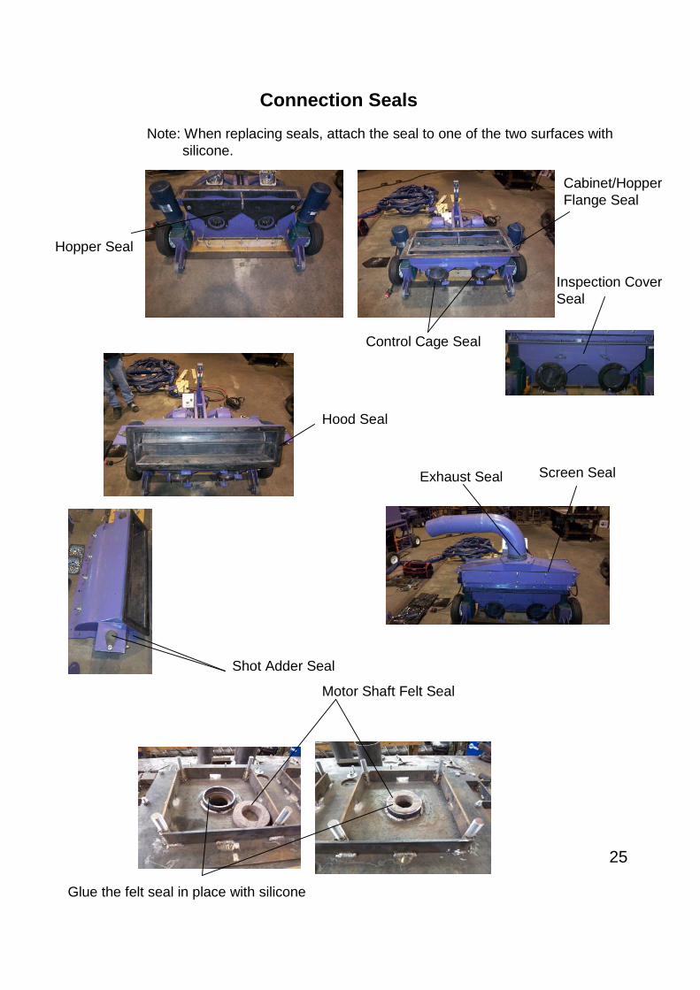
Connection Seals
Hopper Seal
Cabinet/HopperFlange Seal
Control Cage Seal
Hood Seal
Screen SealExhaust Seal
Inspection CoverSeal
Shot Adder Seal
Note: When replacing seals, attach the seal to one of the two surfaces withsilicone.
Motor Shaft Felt Seal
Glue the felt seal in place with silicone

26
Dust Collector Parts
Power Cable Goyen Valve
Blower
Blower Motor
Steering HandleDust Collector Frame
Drum Ratchet
Tire AssemblyMonometer
Filter

27
Dust Collector Inspection and Maintenance
Before beginning maintenance work, all power sources (Electrical, Pneumatic, Mechanical) must be lockedoff, tied off or otherwise neutralized to be considered harmless. It is important that operators andmaintenance personnel receive regular equipment safety training and have a thorough working knowledgeof all electrical, pneumatic and mechanical aspects of this equipment and observe all warnings andprecautions.
Check the dust drum often - It must be replaced before it is full to avoid spilling dust. Use a hammer or heavywrench to rap against the drum to determine the dust level.
The dust collector fan exhaust and the monometer reading should be monitored continuously during the cleaningoperation. A loose or damaged filter can allow dust to bypass the filtering process and be discharged into theatmosphere. Clogged filters can make the dust collector inefficient and cause the FasterBlaster to emit dust. Checkthe monometer gauge- If it is 1” or below the filters are ok. If the gage is over 2”, the filters may be clogged.Clean the filters by allowing the air pulse cleaning system to operate, with the dust collector fan off for 10minutes. Poor ventilation will also result in excessive loss of abrasive and can effect the
cleaning quality. Proper ventilation is essential to good performance and environmentally safe operation.
Make sure that the air-pulse cleaning system is working properly and that the air compressor is supplying 80 psiair to the system. Check each Goyen valve to assure that it is pulsing every 3 minutes. The “blow down” signal foreach of the (3) Goyen Valves comes from the programmable controller in the dust collector panel. The program isset to pulse each valve sequentially. Pulse time is set for .01 second On and 3 minutes Off. Each valve blowsdown (3) of the (9) filters every three minutes. If longer or shorter pulse times are required, a program change isnecessary- Contact the factory for program changes. If a valve is not operating, the valve may not be getting asignal from the control panel. Trace the wiring continuity from the valve to the control panel.
Keep the dust collector out of the weather when not in use. During the cleaning project, cover the unit when notin use to protect it from rain. Make sure that the control panel door is tightly sealed at all times to keep out dustand moisture. Caution- make sure that a drum is in place at all times. If the drum is not in place, dust canescape and moisture can collect on the filters. Filters must be kept dry for proper operation.
Replace filters every year. Caution- When replacing filters or drums, wear dust protection equipment asrequired by Federal, State and Local Codes.
Check the condition of power plugs, cables, connectors and support slings every day. Caution-Replace orrepair damaged plugs, cables, connectors and support slings immediately before operating the machine.
Special Note:All abrasive blast equipment must be properly ventilated to be environmentally safe. Proper ventilation benefitsthe operator, the machine efficiency, and minimizes wear and maintenance. Filters must be kept clean and dry.It is important that the dust drum be replaced before it becomes full. The drum should be immediately capped,sealed and stored away from the equipment operation. Dust can be easily ignited when stored in an opencondition. Capping and sealing the drum will eliminate the risk of spillage and minimize the risk of fire orexplosion. Some types of paint dust can be flammable. To minimize the possibility of a dust collector fire,it is important to assure that the filters are clean and are made of fire retardant materials.Only use Donaldson Pt# P527079-016-022 replacement filters ( Do not substitute ).Check the Magnihelixguage often to assure that the filters are clean.

28
Hoist System Parts
Hoist Frame
(4) Bearing
Gear BoxDrive Motor
(2) Hoist Drum
Hoist Shaft
Safety Brake
(2) 5/8” Shackles
(2) 3/8” Hoist Cable x100’
(8) 3/8” Clamp (4 for each cable)(2) 3/8” Thimble
(8) 5/8” Grade 5 Bolt(2) ¾” Grade 5 Bolt

29
Hoist SystemInspection & Maintenance
Grease bearings every 6 months
Check gearbox oil levelevery 12 months-level should be 6”from top of box or approx. centerof shaft. (box must be level).Holds 168 oz. –use Mobile SHC 634
Safety BrakeCover the brake when not inuse to keep water, blast sandand dust from the unit. Dust andwater can cause the brake tomalfunction.
Make sure all shackles are wire tied.All shackles must be 5/8”.Check shackles daily.
Make sure that at least three clamps are used on eachcable and that the clamps are tight.Check and or tighten cables daily.
Check bearing bolts before starting each project. Bearing bolts must be 5/8” Grade 5.
Caution:• Check cables often. If cables become frayed, they must be replaced.• Cable must be hoist-rated at 13,000 lbs.-Call RBW for replacements.• Tighten clamps often- always use at least 3 clamps per cable.• Keep the hoist covered when not in use. Protect the brake, drive and cablesfrom dust and water damage.
Lubricate bearings beforeevery project.
Caution-Cable clampsaddles must be placedon the lifting segment of thecable as shown.“Never Saddle a Dead Horse”.

30
Caution:• Cable ends must be secured properly - When replacing cables, call RBW for cable replacement
specifications and special instruction.
Run the cable end through the slotted hole and then throughthe hole in the side of the drum end wall. Run the cableback through the inside of the hoist drum.
Pull the cable through the drum and out thehole in the opposite side. Clamp thecable in the welded saddle as shown.
Caution:• The brake is a critical safety component. If the Hoist drive should fail and the machine started
to fall, the centrifugal brake will stop the fall. To work properly it must be kept clean and freeof water and dust. Keep the unit covered when not in use.
• If the safety brake jams for any reason or is tripped by a fall, it must be replaced. It is only goodfor one failure.
• The brake must be mounted so it will trip in the right direction. The arrow on the brake mustbe pointed in the direction the cable is hanging. Call RBW for special instructions.
• If the hoist fails and the safety brake engages, do not attempt to disengage the unit.•Use a crane to remove the machine from the hoist cables and call RBW.
Arrow must point in direction cable is hanging
Cable Installation
Safety Brake Instructions

31
Hoist Motor Brake Instructions
ProblemBrake is smoking or the hoist motor circuit overload kicks outrepeatedly.
SolutionBrake disc is jammed with dirt or rust. Clean out the disc and housing.Follow instructions below.
1. Make sure the machine is on the ground and the cables aredisconnected from the machine.
2. Unplugged the power cables at the dust collector.
3. Remove the 4 mounting bolts.
4. Open the brake release arms (this spreads the brake spring plates andallows the disc to turn freely).
5. Slip the brake assembly off of the motor shaft being careful not topull on the brake electrical wires. Support the brake to prevent stresson the wires while cleaning the brake.
6. Try rotating the brake disc. Blow out any rust or sand lodgedbetween the disc and the clamping plates. Work the disc backand forth until it turns freely. If the disc is still tight, the unit willhave to be disassembled for further cleaning. Call RBW beforeattempting to disassemble the brake.
7. After the disc is cleaned, slide the assembly back onto the motorshaft and install the bolts.
8. Caution- make sure you engage the brake spring platesby closing the release arms.
32
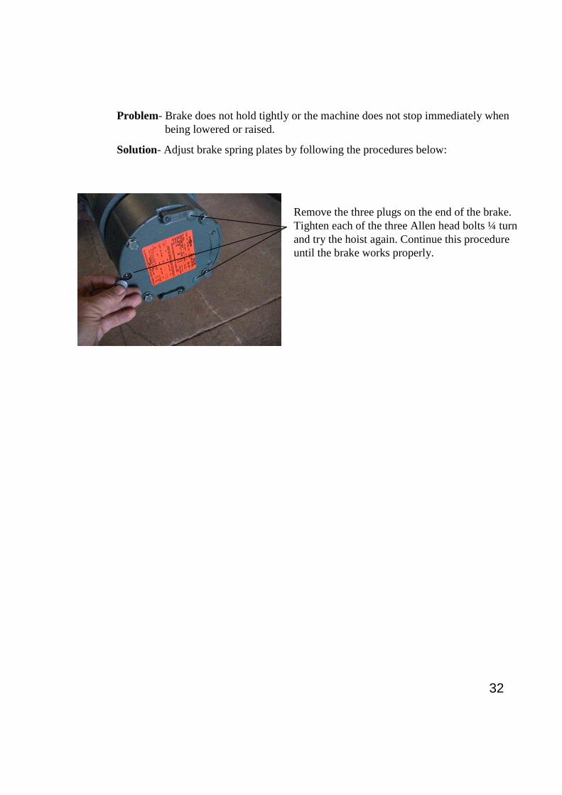
Problem- Brake does not hold tightly or the machine does not stop immediately whenbeing lowered or raised.
Solution- Adjust brake spring plates by following the procedures below:
Remove the three plugs on the end of the brake.Tighten each of the three Allen head bolts ¼ turnand try the hoist again. Continue this procedureuntil the brake works properly.

33
Set Up & Operation Instructions (Floors & Roofs)
To pick up the machine, place a lifting strap on each side of the machine using a 5/8” shacklein the lifting lugs shown above. The machine is balanced at this point so it will be level.
The weight of the machine is around 1500 lbs.Caution-Never lift the machine with the motor lugs. They are formotor lifting only.
Before placing the machine on the roof or floor, make sure that thefour seal support cables are holding the seal up in place around theblast cabinet. If the cabinet edge rides up over the seal frame, theseal will not float along the floor and the machine will not moveproperly. The seal will also be damaged from the blast.
Blast Cabinet
Seal Frame
Place the machine on the roof or floor and make sure that the seal is seated tight to the surfaceand that the support cables are not too tight which would hold the seal up off of the floor. TheCables should have some slack so the seal can float along over wavy surfaces without pullingaway from the floor. The cables can be adjusted by loosening the cable locking bolt.
Cable locking bolt
Caution- when cleaning roofs, a safety cable must be attached to the machine to assurethat it can’t drive off of the tank. Use a 3/8” cable and attach it with a 5/8” shackle on theleft side lug as shown above. Attach the other end to the center stand pipe on the tank.The cable must be attached at the center of the tank and adjusted so the roof can becleaned near the edge and that the machine could not drive off the edge at any pointaround the perimeter.
Step 1Lifting
Step 2
Step 3
Adjust the level of the machineby cranking the swivel wheel upor down. The blast cabinet shouldbe perpendicular with the floor.

34
Step 4
To lift the dust collector, connect lifting straps to the four corner lugs on the top of the housing.A fork lift can also be used to off load the unit as shown above. The unit weighs around 1200 Lbs.
Caution- If you are cleaning the roof of a tank, the dust collector must be placed on the roof so thatthe power cable harness and the exhaust hose will be long enough to reach the edge of thetank and that you will have access to the electrical controls during operation. Do not attempt tooperate the machine on the roof with the dust collector on the ground.
Caution- The dust collector tires are free rolling (no brake). Personnel must support the unit andtie it off when it is placed on the roof. Roll the unit up to the center stand pipe and tie it downsecurely.
Lifting Lug
Cable Slings
Plug in the blast machine wiring harness.Connect the cable support sling to a shackleon the dust collector. This keeps slack betweenthe sling and the plugs so wires are notpulled loose when moving the dust collector.
All plugs are different types and are color codedto assure that they are always connectedproperly.
Connect the two Blast Motor plugs. Red plug to red receptacleand black plug to the black receptacle.
Connect the four small plugsas shown.
Screw Conveyor
Speed Control
Right Drive Tire
Left Drive Tire
Step 5
The dust collectorcan be picked up by afork lift. Place forkswithin the frame slotsas shown.
Place forks through slots
35
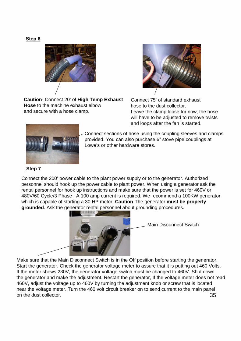
Caution- Connect 20’ of High Temp ExhaustHose to the machine exhaust elbowand secure with a hose clamp.
Connect 75’ of standard exhausthose to the dust collector.Leave the clamp loose for now; the hosewill have to be adjusted to remove twistsand loops after the fan is started.
Step 6
Connect sections of hose using the coupling sleeves and clampsprovided. You can also purchase 6” stove pipe couplings atLowe’s or other hardware stores.
Connect the 200’ power cable to the plant power supply or to the generator. Authorizedpersonnel should hook up the power cable to plant power. When using a generator ask therental personnel for hook up instructions and make sure that the power is set for 460V or480V/60 Cycle/3 Phase . A 100 amp current is required. We recommend a 100KW generatorwhich is capable of starting a 30 HP motor. Caution-The generator must be properlygrounded. Ask the generator rental personnel about grounding procedures.
Step 7
Make sure that the Main Disconnect Switch is in the Off position before starting the generator.Start the generator. Check the generator voltage meter to assure that it is putting out 460 Volts.If the meter shows 230V, the generator voltage switch must be changed to 460V. Shut downthe generator and make the adjustment. Restart the generator, If the voltage meter does not read460V, adjust the voltage up to 460V by turning the adjustment knob or screw that is locatednear the voltage meter. Turn the 460 volt circuit breaker on to send current to the main panelon the dust collector.
Main Disconnect Switch
36
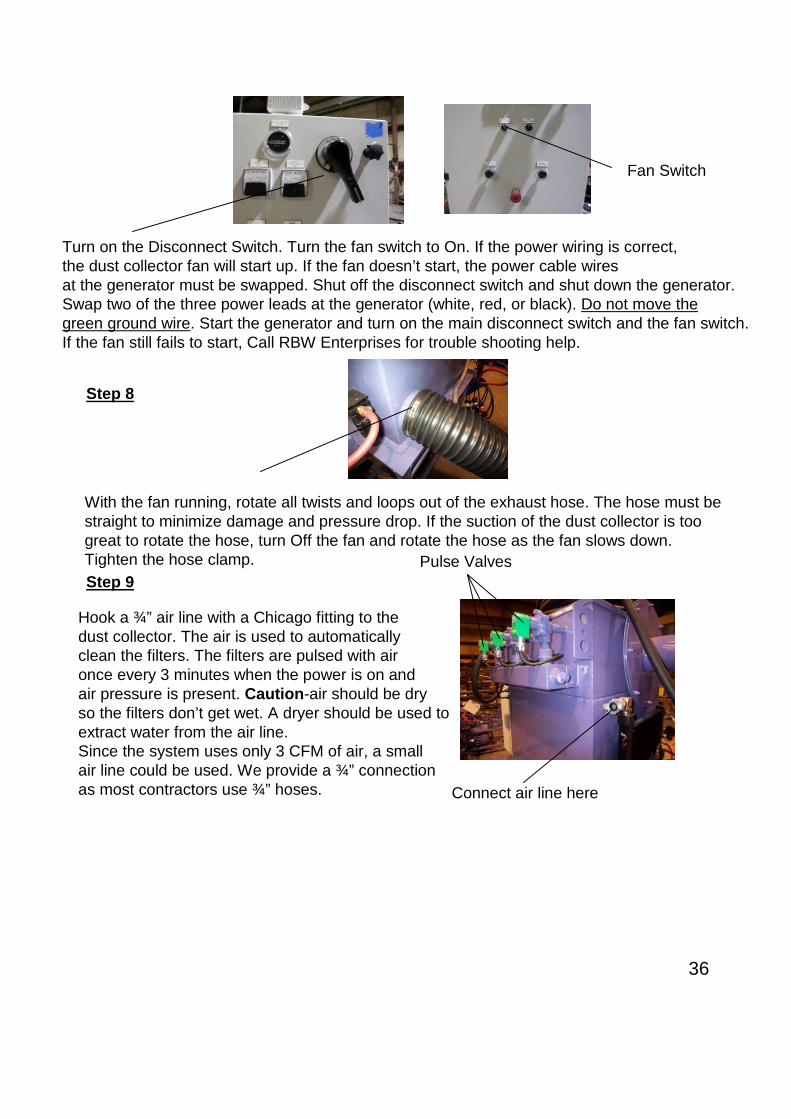
Turn on the Disconnect Switch. Turn the fan switch to On. If the power wiring is correct,the dust collector fan will start up. If the fan doesn’t start, the power cable wiresat the generator must be swapped. Shut off the disconnect switch and shut down the generator.Swap two of the three power leads at the generator (white, red, or black). Do not move thegreen ground wire. Start the generator and turn on the main disconnect switch and the fan switch.If the fan still fails to start, Call RBW Enterprises for trouble shooting help.
Fan Switch
Step 8
With the fan running, rotate all twists and loops out of the exhaust hose. The hose must bestraight to minimize damage and pressure drop. If the suction of the dust collector is toogreat to rotate the hose, turn Off the fan and rotate the hose as the fan slows down.Tighten the hose clamp.
Step 9
Hook a ¾” air line with a Chicago fitting to thedust collector. The air is used to automaticallyclean the filters. The filters are pulsed with aironce every 3 minutes when the power is on andair pressure is present. Caution-air should be dryso the filters don’t get wet. A dryer should be used toextract water from the air line.Since the system uses only 3 CFM of air, a smallair line could be used. We provide a ¾” connectionas most contractors use ¾” hoses. Connect air line here
Pulse Valves

37
Check the dust collector fan drive speed. The drive is preset to run at 60 cycle which iswhere it should be set for horizontal work. When cleaning vertical surfaces you need morevacuum to eliminate abrasive leakage. Caution, do not run the motor faster than 70 cycle.The lower you can run it without leakage, the less heat you will generate. Lower heat andless vacuum is better for the exhaust hose. If the speed is set higher than 60 cycle, lowerit down to 60 for horizontal applications.
If the speed is above 60 cycle, push the Mode Button and the display will flash showing theA00-0 cycle parameter set point.
Push the Set Button and the cycle settingwill flash allowing you to change it.
Push the Arrow Button to move theflashing digit to the digit to theright of the six.
Step 10

38
Push the Down Arrow Button to lower theNumber, one digit at a time, down to zero.Note: You must change the speed slowly,one digit at a time or the drive will overload.
Then push the set button again to set the cycle.
Note: The exhaust hose must be connected between the dust collector and the machineand the dust collector barrel must be in place or the drive will over load and shut down.
The next time you start the drive it will come up to the speed you set it at last. Be sure toturn it back down to 60 when cleaning floors. If you have trouble with the hose collapsing,due to the extra heat and vacuum, a special high temp hose is available.
Step 11
Before operating the machine, you must setthe Mode Switch to the proper position;Horizontal or Vertical. Since we are running ona floor or roof, set the mode switch to horizontal.
Mode Switch

39
Next check out the machine operations. Place the speed dial on the machine to 3 or 4.Press the Forward button on the remote control. The machine will move forward. Oncethe machine is moving, you can let up on the button and the machine will continue to moveforward. Press the Forward button again and the machine will stop.
Speed Dial
Forward Button
Press the Reverse button on the remote control. The machine will move backwards. Oncethe machine is moving, you can release the button and the machine will continue moving backward.Press the Reverse button again and the machine will stop.
Reverse Button
The machine must be moving to turn. Start the machine moving then press the Left SteeringButton on the remote control. The machine will turn to the left. Let up on the button, theturning will stop and the machine will continue in a straight movement.
Left Steering Button

40
Caution : Use good quality S-330 , & or S-390 Steel Shot . If an angular profile is required,add 20% of G-25 Steel Grit. Never use hard grit (GH, GM or GL) or Shot larger than S-390 orany other abrasive material. The use of abrasive other tan S-330, S-390, & G-25 willdamage the blades, impeller, control cage, liners and the blast cabinet.
Use a funnel to add shot. Be sure that the rubber flap is alignedover the adder hole after filling. The flap seals the hole to eliminatevacuum loss. If you lose the funnel provided, they are available at HomeDepot.
Press the Right Steering Button on the remote control. The machine will turn to the right.Let up on the button, the turning will stop and the machine will continue in a straight movement.
Right Steering Button
Step 12 Before loading shot and starting the blast operation, practice running the machineforward, backward and turning at various speeds. You can also shift to full speedmomentarily by holding down the Hoist Up button. When you let up on the button,the machine will slow down to the set speed. This is used to turn quickly. Try it.
Hoist Up Button
Check the blast motor operation. Press the Blast On button. One blast motor should start.Let up on the button. After a timed delay, the second motor should start.. Check the rotationof the motors. Looking from the back of the machine at the motor fan, the left hand motorshould be turning clockwise and the right hand motor should be turning counter clockwise.To stop the blast motors, press the Blast On button again.
Step 13
Blast On Button
Step 14
Now that you are familiar with all the horizontal machine operations, load the machine with shot.If the machine is new or has been cleaned out, pour 50 lbs of shot in each side of the machineto start. Initially, more may have to be added because there are a lot of voids such as hoppercorners that have to be filled with shot. After the initial charge, only small amounts will be addedas needed to maintain amperage. The amount of shot that is fed to the blast wheels during thecleaning process is gauged by the current amperage draw of the blast wheel motors. Themore shot fed to the blast wheel the higher the amperage or the more work the motor is doing.

41
Step 15
After the shot is added, turn on the main disconnect switch, then start the fan. Make sure thatthe air line is connected at the dust collector and the air is turned on at the air compressor.Start the blast wheel motors by pushing the Blast On button. The first motor will start, then aftera delay, the second motor will start. This built in delay starts the motors one at a time so thegenerator is not overloaded- it takes a lot of current to start a 30hp motor.
Blast On Button
Next check the amperage gauge for each motor.The gauge should show amperage of 30 ampsor more.
Amperage GaugeBlast Motor A Amperage Gauge
Blast Motor B
Move the machine forward slowly to observe the cleaning. Note: the blast motors will shut offafter 1 minute unless the machine is moving. This prevents blasting in one spot too long andburning a hole in the roof or floor. Caution- if the machine hangs up on a high weld seam andstalls too long in one spot with the tire drives running, shut off the blast so no damage isdone to the steel.More shot will have to be added to fill in all the hopper voids and to maintain 30 to 35 amps.The optimum cleaning amperage on steel is 35 to 38 amps. Add a little shot at a time until theamperage is steady. During the cleaning process, periodically add around 10 lbs. of shotwhen the amperage falls below 28 amps. After the initial charge, shot does not have to beadded to both sides of the machine. Shot added from one side will get distributed to bothblast wheels.
Practice cleaning by adjusting the speed to achieve the cleaning you require. Themachine can blast going both forward or backward so you don’t have to turn aroundat the end of a pass.
Note: You can stop all operations by pushing the E-StopButton on the remote control or the main panel. If youpush the E-Stop on the remote control, you must holdin the reset button on the main panel for 10 seconds toreset the remote.
E-Stop
Reset Button
E-Stop Button
Pull outto reset
Emergency Stop

42
The shot flow and blast pattern settings are preset at the factory; however you need to knowhow to adjust them. Settings may need to be changed depending on the size of shot being used.The Control Cage Assy. meters the amount of shot that is fed to the wheel and also sets theblast pattern. The hand crank adjusts the shot flow. If you turn the crank in, it will decrease theopening of the feed tube, allowing less shot to the wheel . If you turn it out, it will increase the shotflow to the wheel. You can fine tune the amperage setting of each blast motor by adjusting itscontrol gage hand crank screw.
The overlap for each pass depends on the application, thickness of paint, etc.. In generalyou want to line up the first bolt on the seal with the cut line of the previous pass.
Remember if you run slow enough to get all areas where the paint is thick, you may beover blasting a lot of the areas where paint is thinner. Often times it is better to make adouble pass at a higher speed. The first pass removes the bulk of the paint. You can seewhere the paint is thicker and slow down in those areas on the second pass.This method may produce higher production rates on some applications.
Control Cage LH
Control Cage RH
The end of the cage tube has a rectangular cut out. The tube slides into placeover the blast wheel impeller. The impeller rotates inside the tube. As shot flowsinto the tube from the hopper, the impeller forces it out of the cut out and ontothe blades. The position of the cut out regulates the blast pattern on the floor.The shot leaves the blades about 180 degrees from the cutout. Rotating thecutout clockwise will move the blast pattern to the left. Rotating itcounterclockwise will move the pattern to the right.
Impeller
Rectangular Cut Out
To adjust the blast pattern, loosen thethumb screws and tap the adjusting tabwith a hammer to rotate the control cage.The optimum position is usually with thethumb screw stud centered in the slotas shown.
Adjusting Tab
Thumb Screw
Seal Bolts
Control Cage Thumb Screw

43
Shot flows into the wheel from the hopper through a opening in the control cage tube.The shot flow adjusting disc governs how much shot flows on to the blast wheel. The discis controlled by a hand crank. To increase the shot flow, turn the hand crank counter clockwise.To decrease the flow turn the hand crank clockwise. To shut the shot completely off,turn the crank all the way in until it stops. The double wiper seal keeps the shot from flowing tothe wheel when the crank is fully closed.
Shot Flow Adjusting DiscHopper
Control Cage OpeningHand Crank
Double Wiper Seal

44
Set Up & Operation Instructions (Vertical Walls) Cone Roof Fixture
Step 1 Set up the Fixture and Hoist System
Unroll the power cable so it is freeto uncoil as the fixture is lifted tothe tank roof.
Make sure that the cable harness is laying in the channel andis laying over the round tube. The smooth tube keeps theharness from being damaged from the sharp edge.
Round Tube
Make sure that the hoist support brackets are mounted as close to the front tires and verticalsupport beams as possible. Additional holes are provided in case the hoist has to be movedout further from the tank wall so the cables can clear vents or other obstructions. When thehoist is moved out, additional counter weights will have to be added to the back end of thefixture. Bolt the brackets down to the beam with (4) 5/8” “Grade 5” bolts.
Hoist Support Brackets
Make sure that the cable wrapson the hoist drums are straightand smooth across the drum.
Caution-Make sure that thereare at least (3) 3/8” cable clampson each cable and that they areextremely tight.
Caution-Cable clampsaddles must be placedon the lifting segment of thecable as shown.“Never Saddle a Dead Horse”.

45
Use two straps to lift the fixture (one on each beam). Locate the straps about two feet back fromthe front vertical beams. Double wrap each strap so it won’t slide along the beam during the lift.Pick the fixture off the ground, (if it tips either way, re-adjust the straps so the unit picks up level).Caution- make sure the crane and straps are sized properly for the load. The fixture and the hoistweighs around 2000 lbs.
Place the fixture on the roof with the front tiresabout 3 to 4” from the edge of the tank. Make sure thatthe fixture is sitting square and that the rear of the fixtureis pointed toward the center of the tank.
3 to 4”
Run the cable from the turnbuckle through the rear eye andaround the tanks center stand pipe. Run the cable back throughthe other rear eye and connect it to the opposite turnbuckle,using at least two 3/8” cable clamps. Pull the cable tight aspossible before clamping. Next, pull the two cables together andplace a single clamp about two foot from the stand pipe. This willkeep the fixture running square to the tank.
Single 3/8” clamp
Adjust the ¾” turnbuckles so they will have equal adjustmentin both directions. This will allow for final adjustment afterthe tie-back cable is in place.
Caution- The center stand pipe must be structurally sound and capable of handling 1000 lb.pull at the base. The standpipe must be located in the center of the tank. If it isn’t, special cableconnections must be made. Call RBW for help in set-up.
Step 2
46
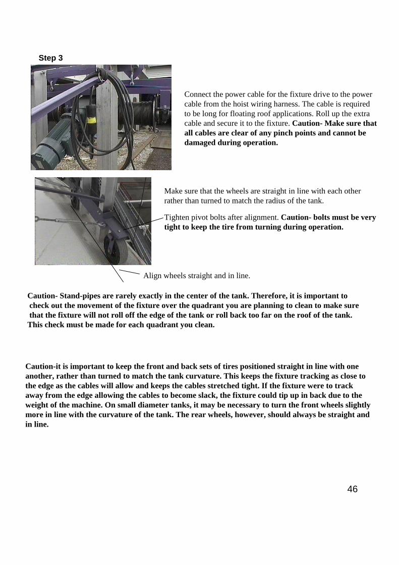
Connect the power cable for the fixture drive to the powercable from the hoist wiring harness. The cable is requiredto be long for floating roof applications. Roll up the extracable and secure it to the fixture. Caution- Make sure thatall cables are clear of any pinch points and cannot bedamaged during operation.
Caution- Stand-pipes are rarely exactly in the center of the tank. Therefore, it is important tocheck out the movement of the fixture over the quadrant you are planning to clean to make surethat the fixture will not roll off the edge of the tank or roll back too far on the roof of the tank.This check must be made for each quadrant you clean.
Caution-it is important to keep the front and back sets of tires positioned straight in line with oneanother, rather than turned to match the tank curvature. This keeps the fixture tracking as close tothe edge as the cables will allow and keeps the cables stretched tight. If the fixture were to trackaway from the edge allowing the cables to become slack, the fixture could tip up in back due to theweight of the machine. On small diameter tanks, it may be necessary to turn the front wheels slightlymore in line with the curvature of the tank. The rear wheels, however, should always be straight andin line.
Make sure that the wheels are straight in line with each otherrather than turned to match the radius of the tank.
Align wheels straight and in line.
Tighten pivot bolts after alignment. Caution- bolts must be verytight to keep the tire from turning during operation.
Step 3

47
(1) Place fixture horizontally on the ground asshown in Photo 1.
(2) Adjust height of adjustable beams based ondimensions of wind girderand knee brace- Photo1. Call RBW withdimensions for proper holepositions and bolt locations.
(3) Make sure that (3) ¾” grade 8 bolts areused at points A inPhoto 1. Make sure that all bolts shown inPhoto 1 are in placeand tightened properly. All bolts used mustbe at least grade 5 unlessotherwise noted.
(4) Make sure that nuts are in place on allrollers and pulleys, and thatthey are free to rotate –Photos 1 & 2.
(5) Bolt the Drive Tire Assembly and Idler TireAssembly on with 5/8”Grade 5 bolts - Photos 3 & 4.
(6) Route the Trolley Drive cable around thebeam as shown in Photos 5.Make sure that the cable will not come incontact with hand rails or thewind girder.
(7) Lift the Fixture Assembly at pick pointsshown in Photo 6
A(Must be at least (3) 3/4” Grade 8 Bolts
At each connection point)
Photo 1
Photo 2
Pulleys
RollersRollers
Rollers
Photo 3 Photo 4
Drive Tire Assembly
Idler Tire Assembly
Floating Roof Fixture Set-Up Page 1 of 3
Photo 6
Lifting Points
Photos 5
Route power cableFrom the drive motorAlong the beams asShown. Use wire tiesTo secure the cable.

48
Floating Roof Fixture Set-Up Page 2 of 3
(7) Pick up the fixture into a vertical position and lower it over the HoistAssembly. Attach the two shackles to the hoist as shown in Photo 7.Be sure to wire tie the shackles and connect the fixture drive powercable.
(8) Raise the assembly up - Photo 8 and place the unit on the tank windgirder as shown in Photo 9.
Shackles
Photo 7
Photo 8
Photo 9
Power Cable

49
3/8” Cable
Internal Rollers
Pivot Bolt
Photo 10
Photo
Photo 11
Drawing 1
Floating Roof Fixture Set-Up Page 3 of 3(9) If the tank has hand rails, the Drive and Idler Tire Assemblies may have to be removed to get the fixture over
the hand rail. If so, set them on the wind girder until the fixture is over the hand rail and then bolt them back on.If the tank wall is too high, the internal roller arm may have to be pivoted up to clear the wall. See Drawing 1.
(10) Move the fixture in towards the tank so the external rollers are riding against the tank wall. Install the 3/8” cablearound the pulleys as shown on Photo 10. The cable must be trapped between the center pulley and thekeeper to assure that the cable cannot come off the pulley. Make sure that the nut is tightened so the centerpulley cannot lift up during operation. Run the cable around the tank and tie it at one end to a stable structurewith three 3/8” cable clamps. Attach the other end to a heavy duty 1 ½ ton tensioning device such as a chainfall, ratchet load binder, come along, etc. Tighten the cable to pull the fixture tight against the wall. The 3/8”cable should be 6x37 IWRC BRT WR with a breaking strength of 15,000 lbs. Caution: Cable stretchesduring operation, check the tension often.
(11) Adjust the internal rollers so they are close to the tank wall- they are for safety only and do not have to touchthe wall at all times.
(12) Cock the drive and idler tires slightly towards the tank wall in the direction that the fixture will be moving.This will keep the fixture tight to the tank wall. Note: You will want to make sure that the blast is good as youproceed, because if you have to go back, you will have to cock the tires back in the opposite direction.
(13) Make a final check to assure that all bolts are in place and are tightened. Then move the fixture under powerto see if it stays in proper position against the tank wall. If all looks good, lower the hoist cables and attachthe machine.
(14) Caution: when cleaning the internal walls of the tank, it is recommended, to blast up the wall and backdown in the same path. Then set the machine on the floor or tank roof with a little slack in the cables beforemoving the fixture over for a new pass. The fixture will have less stress and will be more stable during themovement if the weight of the machine is removed.

50
C-Frame Set Up
Mount the winch base plate on the front cross supportangles as shown. Use (4) grade 8 ½” diameter bolts withlock nuts.If holes do not already exist in the back support angles,drill (2) 11/16” diameter holes in each front top angle16” from the left hand edge of the angle and 10”between holes as shown. Drill the holes in the centerof the two 2” wide angles,1” from the edge.
Mount the cable pulley and tee bar on the front end ofthe fixture flush with the top edge of the beamsas shown. Use 5/8” bolts and lock nuts.
The C-Frame is used to blast clean under stairs and other protrusions such as pipes andsecondary wind girders.
16”10”
Mount the battery and secure it withthe flex strap. Attach the battery cables.
Run the battery cables and the switch cabledownbetween the angles.
Disengage the cable and pull enough cable out torun through the cable pulley as shown.
Payout the cable to the ground and thenRe-engage the winch drive.
Run out or pay in cable using the cableIN/ Out switch.
51
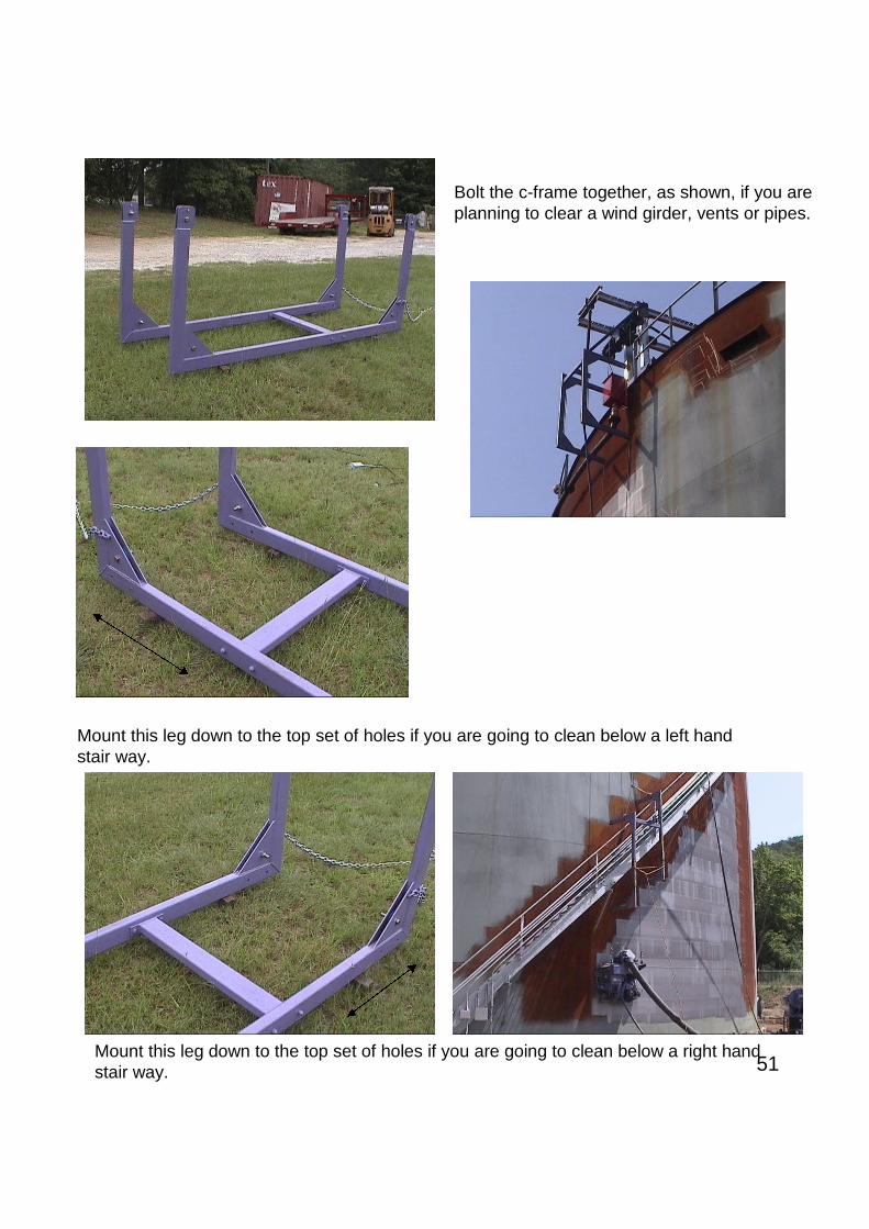
Bolt the c-frame together, as shown, if you areplanning to clear a wind girder, vents or pipes.
Mount this leg down to the top set of holes if you are going to clean below a left handstair way.
Mount this leg down to the top set of holes if you are going to clean below a right handstair way.
52
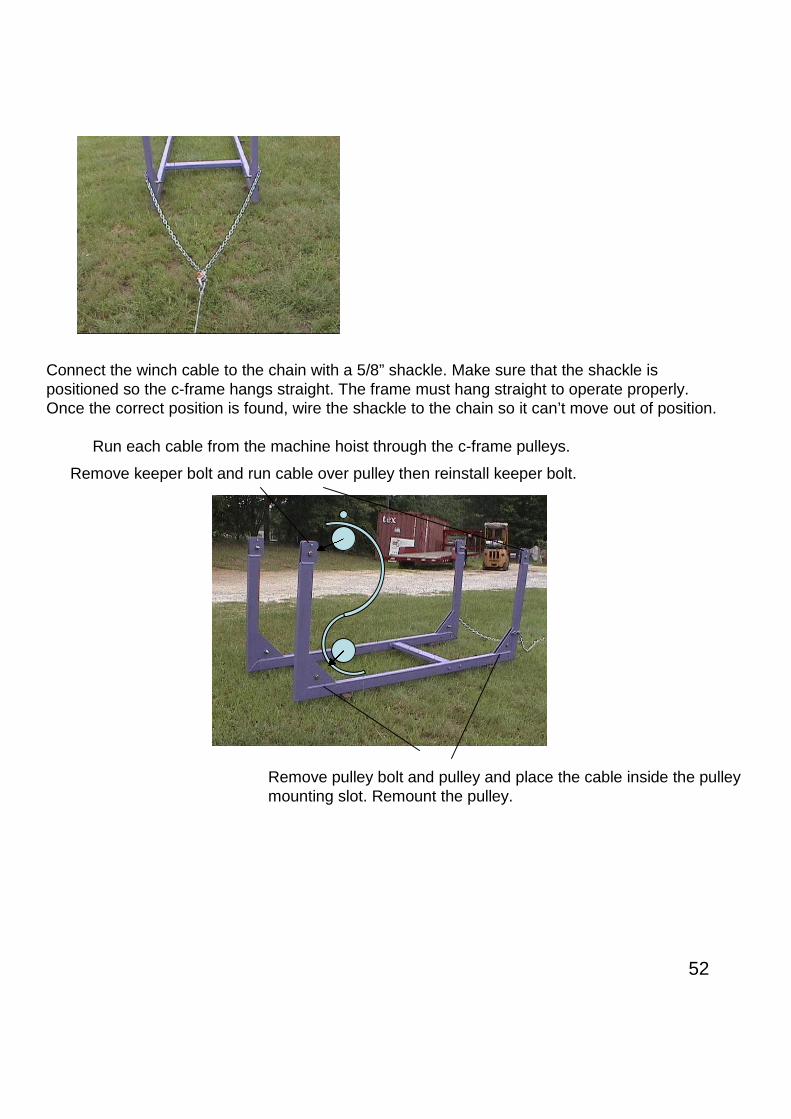
Connect the winch cable to the chain with a 5/8” shackle. Make sure that the shackle ispositioned so the c-frame hangs straight. The frame must hang straight to operate properly.Once the correct position is found, wire the shackle to the chain so it can’t move out of position.
Run each cable from the machine hoist through the c-frame pulleys.
Remove keeper bolt and run cable over pulley then reinstall keeper bolt.
Remove pulley bolt and pulley and place the cable inside the pulleymounting slot. Remount the pulley.

53
As the machine is moved horizontally, use the C-Frame winch switch to raiseand lower the C-Frame to clear the stairway. Caution- a man must be stationedon the roof to operate the C-Frame winch. The operator on the ground signals the winchoperator to raise or lower the C-Frame.

54
Connect the hoist cables to the main panel. The hoistcable harness has three plugs. The largest plug is thepower cable for the hoist motor. The middle size plugis the brake cable for the hoist motor and the smallestplug is the cable for the fixture drive. Make sure thatthe cable support sling is attached to the support shackle.
Step 4
Switch the Mode Selector Switch to Vertical.
Turn the machine drive speed to 0. Thisspeed knob adjusts the speed of the drive tireswhen cleaning walls of dome and knuckle rooftype tanks where the machine will be tracking upand over the dome or knuckle.
The Mode Switch must be turned to the “Vertical”position when cleaning walls. This selects theprogram that allows the hoist and fixture tooperate from the remote control.
Cable Slings
Plug in the blast machine wiring harness.Connect the cable support slings to a shackleon the dust collector. This keeps slack betweenthe sling and the plugs so wires are notpulled loose when moving the dust collector.
All plugs are different types and are color codedto assure that they are always connectedproperly.
Connect the two Blast Motor plugs. Red plug to red receptacleand black plug to the black receptacle.
Connect the four small plugsas shown.
Screw Conveyor
Speed Control
Right Drive Tire
Left Drive Tire
Step 5
Hoist Power Plug
Hoist Brake Plug
Fixture Drive Plug

55
Connect the exhaust hose to the exhaustelbow and secure with a hose clamp.
Connect the other end of the exhaust hoseto the dust collector. Leave the clamp loose,for now; the hose will have to be adjusted toremove twists and loops after the fan isstarted.
Step 6
Connect sections of hose using the coupling sleeves and clampsprovided. If you need more couplings in the future you canpurchase stove pipe couplings at Lowe’s or other hardwarestores.
Connect the 200’ power cable to the plant power supply or to the generator. Authorizedpersonnel should hook up the power cable to plant power. When using a generator, ask therental personnel for hook up instructions and to make sure that the power is set for 460V or480V/60 Cycle/3 Phase . A 100 amp current is required. We recommend a 100 KW generatorcapable of starting a 30 HP motor. The generator must be properly grounded. Ask thegenerator rental personnel about proper grounding.
Step 7
Make sure that the Main Disconnect Switch is in the Off position before starting the generator.Start the generator. Check the generator voltage meter to assure that it is putting out 460 Volts.If the meter shows 230V, the generator voltage switch must be changed to 460V. Shut downthe generator and make the adjustment. Restart the generator; if the voltage meter does not read460V adjust the voltage up to 460V by turning the adjustment knob or screw that isusually located near the voltage meter. Turn the 460 volt circuit breaker On to sendcurrent to the main panel on the dust collector.
Main Disconnect Switch
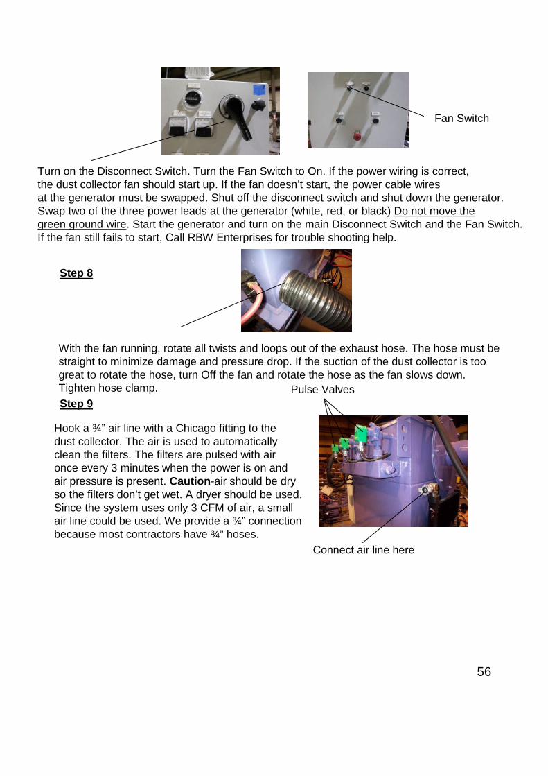
56
Turn on the Disconnect Switch. Turn the Fan Switch to On. If the power wiring is correct,the dust collector fan should start up. If the fan doesn’t start, the power cable wiresat the generator must be swapped. Shut off the disconnect switch and shut down the generator.Swap two of the three power leads at the generator (white, red, or black) Do not move thegreen ground wire. Start the generator and turn on the main Disconnect Switch and the Fan Switch.If the fan still fails to start, Call RBW Enterprises for trouble shooting help.
Fan Switch
Step 8
With the fan running, rotate all twists and loops out of the exhaust hose. The hose must bestraight to minimize damage and pressure drop. If the suction of the dust collector is toogreat to rotate the hose, turn Off the fan and rotate the hose as the fan slows down.Tighten hose clamp.
Step 9
Hook a ¾” air line with a Chicago fitting to thedust collector. The air is used to automaticallyclean the filters. The filters are pulsed with aironce every 3 minutes when the power is on andair pressure is present. Caution-air should be dryso the filters don’t get wet. A dryer should be used.Since the system uses only 3 CFM of air, a smallair line could be used. We provide a ¾” connectionbecause most contractors have ¾” hoses.
Connect air line here
Pulse Valves

57
Check the dust collector fan drive speed. The drive is preset to run at 60 cycle which iswhere It should be set for horizontal work. When cleaning vertical surfaces you need morevacuum to eliminate abrasive leakage. Caution, do not run the motor faster than 70 cycle.The lower you can run it without leakage the less heat you will generate. Lower heat andless vacuum is better for the exhaust hose. If the speed is set at 60 cycle raise it up to 65 forvertical cleaning.
If the speed is set at 60 cycle, push the Mode Button and the display will flash showing theA00-0 cycle parameter set point.
Push the Set Button and the cycle settingwill flash allowing you to change it.
Push the Arrow Button to move theflashing digit to the digit to theright of the six.
Step 10

58
Push the Up Button to raise the number,one digit at a time up to 65.Note: You must change the speed slowly(one digit at a time) or the drive will overload.
Next push the Set Button again to set the cycle.
Note: The exhaust hose must be connected between the dust collector and the machine;the machine seal must be up against the wall, and the dust collector barrel must be inplace or the drive will over load and shut down.
The next time you start the drive, it will come up to the speed you set it at last. Be sure toturn it back down to 60 when cleaning floors. If you have trouble with the hose collapsingdue to the extra heat and vacuum, a special high temp hose is available.
Step 11
Before operating the machine, you must setthe Mode Switch to the proper position,horizontal or vertical. Since we are running ona floor or roof, set the mode switch to horizontal.
Mode Switch
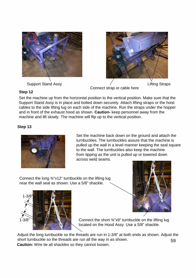
59
Step 12
Set the machine up from the horizontal position to the vertical position. Make sure that theSupport Stand Assy is in place and bolted down securely. Attach lifting straps or the hoistcables to the side lifting lug on each side of the machine. Run the straps under the hopperand in front of the exhaust hood as shown. Caution- keep personnel away from themachine and lift slowly. The machine will flip up to the vertical position.
Support Stand AssyConnect strap or cable here
Lifting Straps
Step 13
Set the machine back down on the ground and attach theturnbuckles. The turnbuckles assure that the machine ispulled up the wall in a level manner keeping the seal squareto the wall. The turnbuckles also keep the machinefrom tipping as the unit is pulled up or lowered downacross weld seams.
Connect the long ¾”x12” turnbuckle on the lifting lugnear the wall seal as shown. Use a 5/8” shackle.
Connect the short ¾”x9” turnbuckle on the lifting luglocated on the Hood Assy. Use a 5/8” shackle.
Adjust the long turnbuckle so the threads are run in 1-3/8” at both ends as shown. Adjust theshort turnbuckle so the threads are run all the way in as shown.
1-3/8”
1-3/8”
Caution: Wire tie all shackles so they cannot loosen.

60
Caution : Use good quality S-330 , &/or S-390 Steel Shot . If an angular profile is requiredadd 20% of G-25 Steel Grit. Never use hard grit (GH, GM or GL) or Shot larger than S-390 orany other abrasive material. The use of abrasive other than S-330, S-390, & G-25 willdamage the blades, impeller, control cage, liners and the blast cabinet.
Step 14
Turn on the main disconnect switch andpush the Hoist Down button to lower thehoist cables. Push it again to stop thehoist.
Hoist Down Button
Attach the hoist cables to the turnbuckles with5/8” shackles. Wire tie all shackles so they can’tcome loose.
Step 15Press the Hoist Up button and lift the machine off the groundand onto the wall. Press the button again to stop the hoist.
Press Steering Rightto speed up the hoist.
Press Steering Leftto slow down the hoist.
The steering buttons used in the horizontal mode become hoist speed buttons when the modeswitch is in the vertical position. Each time you press the buttons the speed is increased ordecreased by 1 cycle. Full speed is 60 cycle.
Check the machine to make sure that it is hanging level from side to side.Adjust one of the cables if the machine is not level. Be sure to tighten the cable clamps securely.
Adjust cables if necessary.
Check to make sure that the machine is hangingsquare to the wall. Adjust the turnbuckles if required.
Step 16Add 50 lbs of shot in both sides ofthe machine using the funnel provided.Be sure that the rubber flap is alignedover the adder hole after filling. The flapseals the hole to eliminate vacuum loss.If you lose the funnel provided, theyare available at Home Depot.
Tape the horizontal flapdown to prevent leakagewhen filling.
Wire Tie

61
Step 17
Remove the tires when cleaningcone roof tanks. The tires are usedif you are cleaning the walls of a domeroof and are planning to clean theknuckle of the tank. Call RBW Enterprisesfor more info on cleaning knuckles of adome roof.
Remove tires
After the shot is added, turn on the Main Disconnect Switch, then start the fan. Make sure thatthe air line is connected to the dust collector and the air is turned on at the air compressor.When in the vertical mode, it is necessary to push two buttons to start the blast wheels. Thisis a safety feature to keep from accidentally starting the blast wheels when the machine issitting on the ground away from the wall.Start the blast wheel motors by pushing the Blast On Button and the Right Steering Button.(Note: To stop the blast motors, press only the Blast On Button again) The first motor will start
then after a delay, the second motor will start. This built-in delay starts the motors one at a timeso the generator is not overloaded. It takes a lot of current to start a 30hp motor. Next checkthe amperage gauge for each motor. The gauge should show amperage of 30 amps or more.
Blast On Button
Step 18
Amperage GaugeBlast Motor A
Amperage GaugeBlast Motor B
Note: The speed knob has nofunction when in the vertical mode.
Since the amp meters cannot be seen whenthe machine is high on the wall, amp metersare also located on the main panel.
Adjust the shot flow to bring the amperage up or down to approximately 35 amps.See pages 31 & 32 for adjustment procedure.
Right Steering Button

62
Step 19
Start the machine moving up the wall by pushing the Hoist Up switch. After the machine ismoving, let up on the switch and the machine will continue to move up the wall until you pushthe button again.
Hoist Up Button
Adjust the speed to achieve the cleaningyou require. Increase the speed bypushing the Steering Right Button.
Decrease the speed by pushing the Steering Left Button.
When the machine reaches the top of the wall, stop thehoist by pushing the Hoist Up Button again.
Then move the fixture to the left or right by pushing theFixture Left or Right Button. You must hold down the buttonto keep the fixture moving. When you release the buttonthe fixture will stop.
Fixture RightFixture Left
Start the machine moving back down the wall by pushing the Hoist Down Button. After themachine is moving, let up on the switch- the machine will continue to move down the wall untilyou push the button again.When the machine gets to the bottom, stop the hoist by pushing the Hoist Down Button again.Move the fixture again and repeat step 19. You must overlap the previous pass to assureproper cleaning. Practice the process to keep the overlaps to a minimum.You can adjust the machines path during the cleaning process by movingthe position of the fixture.
Note: You can stop all operations by pushing the E-StopButton on the remote control or the main panel. If youpush the E-Stop on the remote control, you must holdin the reset button on the main panel for 10 seconds toreset the remote.
E-Stop
Reset Button
E-Stop Button
Pull outto reset
Emergency Stop

63
Machine Setup
Special Applications
Setup Procedures vary on different types of tanks. Fixtures are available for; floating rooftanks (where the fixture rides on the wind girder), dome roof tanks, internal wall cleaning (wherea trolley drive and I-beam is used), ship hull cleaning, internal walls on floating roof tanks, etc.
If you have a special application, call RBW Enterprises. We will provide the proper fixturesystem and the proper setup instructions for the application.
Caution- do not attempt to hang the FasterBlaster machine on unauthorized fixtures. Fixtures mustbe approved by RBW Enterprises. 770-251-8989.
Cone Roof Tank
Floating Roof TankInternal Cleaning
Ship Fixture
Dome Roof Tank
Floating RoofTankExternal Cleaning
Tank Fixtures

64
Main Panel Controls
Main Control Panel islocated on the dust collector.It controls all machine functions.
Disconnect SwitchTurns power on and off
Amperage MeterShows the amount of current theblast wheels are pulling-the higher theamperage the more shot is being thrownby the blast wheel. Caution-do not operateOver 40 amps.
Hour MeterShows how many hoursthe blast wheels have operated.
Hoist Drive Speed IndicatorShows the speed of the hoistwhen blast cleaning in the verticalMode.
Fan ON/OFF SwitchTurns the dust collector fanOn and Off.
Mode Selector SwitchSelects the operating programfor horizontal or verticaloperation.
Fixture Drive SpeedSets the speed of the rooffixture when blasting verticalsurfaces.
Machine Drive SpeedSets speed of the machine drive wheelswhen cleaning vertical walls.
Emergency Stop ButtonPush in to stop all operation.Pull out to reset.
Remote ControlE-Stop Reset ButtonPush & hold for 10 secondsto reset remote control afterE-stop has been activated.

65
Hoist Power Plug Receptacle
Blast Motor Plug Receptacle
Hoist Brake Plug Receptacle
Fixture Drive Plug Receptacle
Fan Power Cable
Power Cable to RightTire Drive Motor
Power Cable to LeftTire Drive Motor
Spare Power Cable forFuture Options.
Power Cable for SpeedAdjustment Dial on theMachine
110 Volt Receptacle

66
Inside the Control Panel
MPCB-110Blast Motor “A” Circuit BreakerProtects motor. Will trip if motoroverloads or shorts out.
MPCB-115Blast Motor “B” Circuit BreakerProtects motor. Will trip if motoroverloads or shorts out.
MS-115Motor Starter for Blast Motor “B”Sends 460 volt current to the motor.
MS-110Motor Starter for Blast Motor “A”Sends 460 volt current to the motor.
Main Disconnect SwitchTurns on and shuts off powerto the Panel
MPCB-118Hoist Circuit BreakerProtects motor. Will trip if motoroverloads or shorts out.
Current MonitorStops operation if the powercables are hooked up wrongor if voltage is not properon all three legs. Assures thatmotors will rotate in the rightdirection.
MS-214FFixture Drive Motor “Left”Sends power to the fixturedrive motor to move thefixture to the left.
MS-214RFixture Drive Motor “Right”Sends power to the fixturedrive motor to move thefixture to the right.
MS-233FMachine Drive Motor in Horizontal ModeFixture Drive Motor in Vertical ModeMoves machine forward in horizontal mode.Moves fixture to the right in vertical mode.
MS-240RMachine Drive Motor in Horizontal ModeFixture Drive Motor in Vertical ModeMoves machine forward in horizontal mode.Moves fixture to the right in vertical mode.
MS-240FMachine Drive Motor in Horizontal ModeFixture Drive Motor in Vertical ModeMoves machine backward in horizontal mode.Moves fixture to the left in vertical mode.
MS-233RMachine Drive Motor in Horizontal ModeFixture Drive Motor in Vertical ModeMoves machine backward in horizontal mode.Moves fixture to the left in vertical mode.

67
24 Volt Power SupplySupplies power to operatethe CPU and the RemoteControl.
MS-105Dust Collector Fan MotorSupplies power to the VF fan Drive
OL-105Dust Collector Fan Motor Over-LoadProtects fan motor and VF Drive
MS-465Hoist motor BrakeSupplies power to release the Hoist Brake
CB-467Hoist Motor Brake CircuitBreaker
Control Relay for Hoist VF DriveHoist Drive UP
CR-404
Control Relay for Hoist VF DriveHoist Drive Down
CR-405
CR-405Remote Control E-Stop(Emergency Stop)
PLC
CPU
Input ModuleDC Current
Input ModuleAC Current
CB-207Fixture Drive CircuitBreaker
CB-226Machine Drive CircuitBreaker
CB-247Optional Drive CircuitBreakerOutput Modules
CB-125Main PrimaryCircuit Breaker460VAC
CB-128SecondaryCircuit Breaker110VAC
CB-130110V Outlet Circuit Breaker

68
Variable Frequency Drive for Hoist
T127 Transformer (3KVA)Drops 460v. to 110v.
Braking ResisterFor Hoist Drive
Line Reactor
ReceiverFor Remote Control
TransmitterFor Remote Control
DC DriveFor Machine DriveMotors
DC DriveFor Fixture DriveMotor
CR-440Full Speed Control Relay CR-439
Pot Control Relay
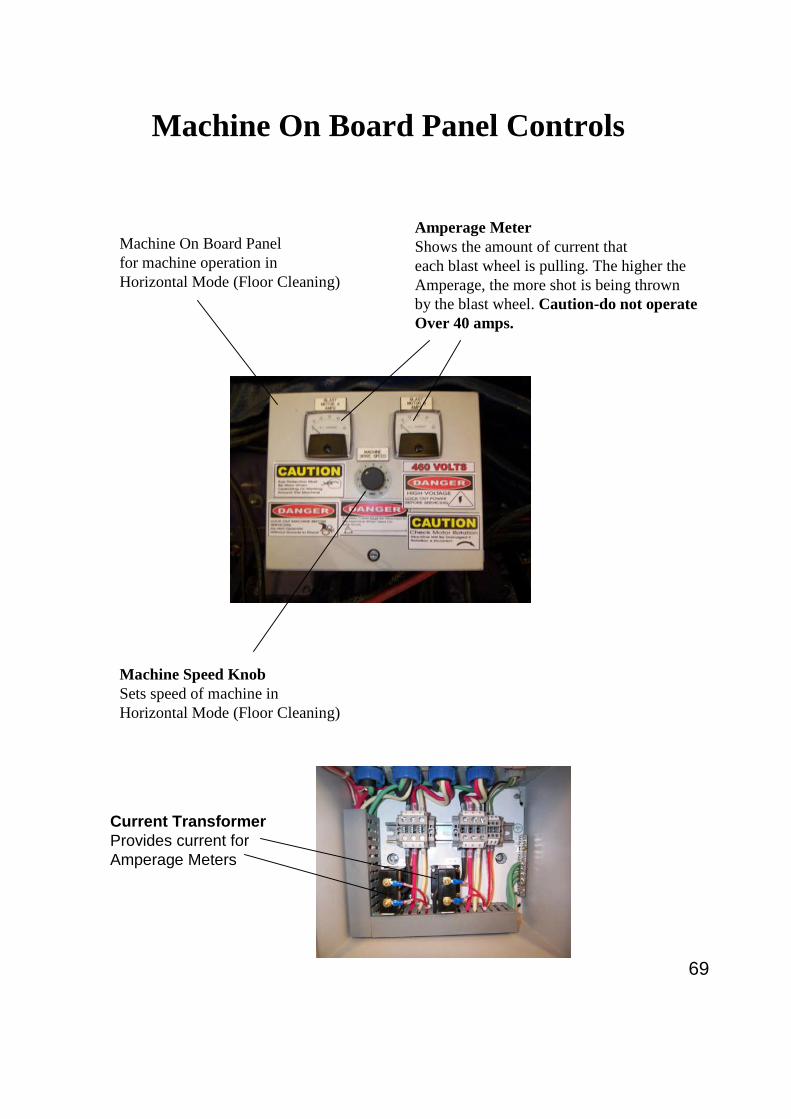
69
Machine On Board Panel Controls
Machine On Board Panelfor machine operation inHorizontal Mode (Floor Cleaning)
Amperage MeterShows the amount of current thateach blast wheel is pulling. The higher theAmperage, the more shot is being thrownby the blast wheel. Caution-do not operateOver 40 amps.
Machine Speed KnobSets speed of machine inHorizontal Mode (Floor Cleaning)
Current TransformerProvides current forAmperage Meters

70
Hand-Held Remote Controls
Press and hold for Left Travel of thefixture when in vertical mode. Release buttonto stop.Forward Travel of machine (when in horizontalMode). Press until machine starts moving thenrelease and the machine will continue movinguntil you press the button again to stop.
Press until the machine starts moving up thewall then release and the machine willcontinue moving until you press the buttonagain to stop.
E-Stop (Emergency Stop)Stops all operation- to reset you mustpress and hold the reset button on themain control panel for 10 seconds.
Blast Motor On/OffPress for 3 seconds to start.Press again to stop.
Steer Left Bump or tapthe button too make slightsteering corrections. Hold downlonger for turning.
Steer Right Bump or tapthe button too make slight steeringcorrections. Hold down longerfor turning.
Press and hold for Right Travel of thefixture when in vertical mode- release buttonto stop.Reverse Travel of machine (when in horizontalMode). Press until machine starts moving thenrelease and the machine will continue movinguntil you press the button again to stop.
Press until the machine starts moving downthe wall then release and the machine willcontinue moving until you press the buttonagain to stop.
In vertical mode; bump buttonto slow down the hoist.
In vertical; mode bump buttonto speed up the hoist.
In horizontal mode, press this button to goto full speed for machine forward or reversemovement. Release the button and the speedwill return to the set speed.

71
Hand-Held Remote Controls
Steer LeftIn Horizontal Mode-Bump ortap the button to make slightsteering corrections. Hold downlonger for turning.
Steer RightIn Horizontal Mode-Bump or tapthe button too make slight steeringcorrections. Hold down longerfor turning.
In Vertical Mode- Bump buttonto slow down the hoist.
In Vertical Mode- Bump buttonto speed up the hoist.
Hoist UPIn Vertical Mode-Press until themachine starts moving up the wallthen release and the machine willcontinue moving until you pressthe button again to stop.
In Horizontal Mode- Press thisbutton to go to full speed formachine forward or reversemovement. Release the buttonand the speed will return tothe set speed.
DrivingIn Vertical Mode-Press and holdfor Left Travel of the fixture.Release button to stop.
In Horizontal Mode-Press untilmachine starts moving forward,release and the machine willcontinue moving until you pressthe button again to stop.
Activate Remote ControlON Switch
Blast Motor On/OffPress for 3 seconds to start.Press again to stop.
E-Stop (Emergency Stop or Machine Shut Down)Stops all operation- to reset you must press theGreen On Switch.
Hoist DownIn Vertical Mode-Press until themachine starts moving down thewall then release and the machinewill continue moving until youpress the button again to stop.
DrivingIn Vertical Mode-Press and holdfor Right Travel of the fixture.Release button to stop.
In Horizontal Mode-Press untilmachine starts moving backward,release and the machine willcontinue moving until you pressthe button again to stop.
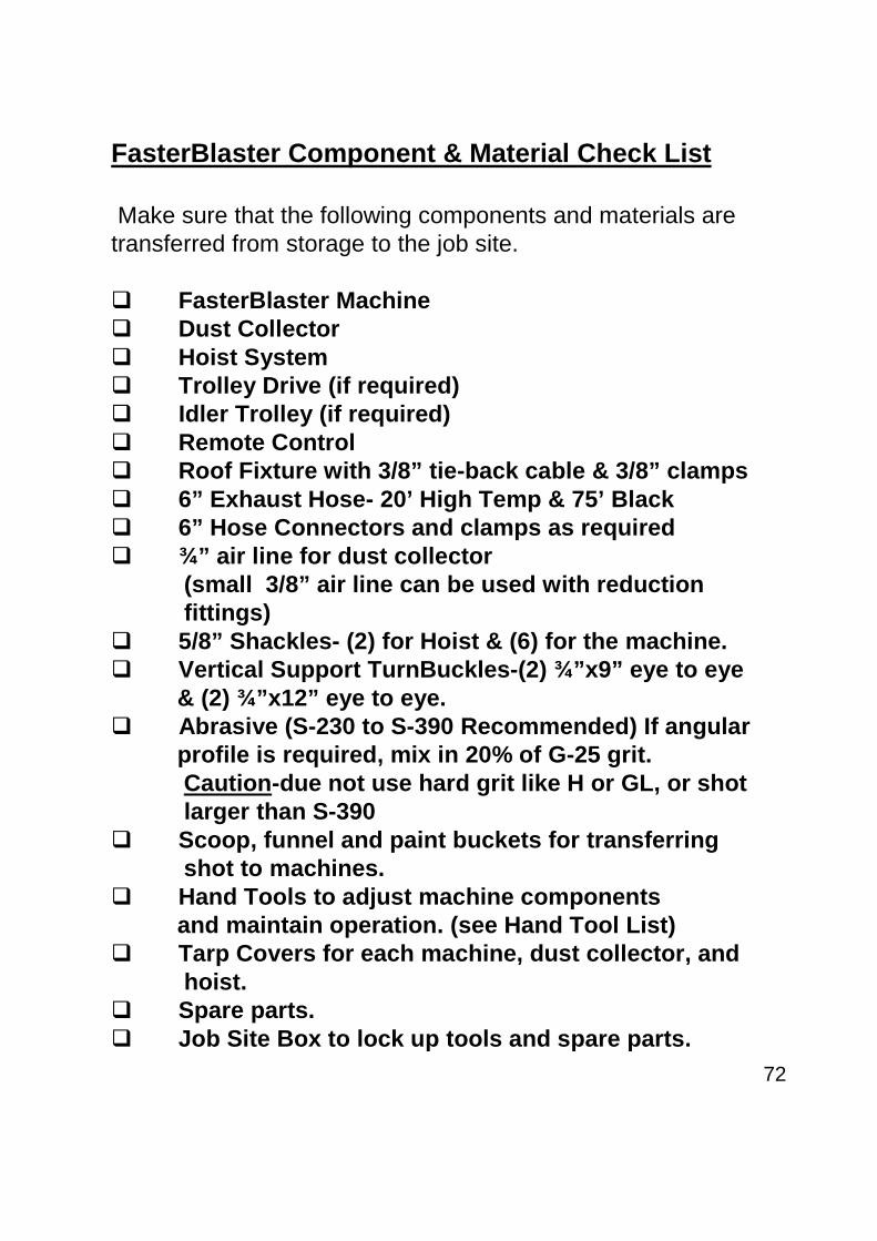
72
FasterBlaster Component & Material Check List
Make sure that the following components and materials aretransferred from storage to the job site.
FasterBlaster Machine Dust Collector Hoist System Trolley Drive (if required) Idler Trolley (if required) Remote Control Roof Fixture with 3/8” tie-back cable & 3/8” clamps 6” Exhaust Hose- 20’ High Temp & 75’ Black 6” Hose Connectors and clamps as required ¾” air line for dust collector
(small 3/8” air line can be used with reductionfittings)
5/8” Shackles- (2) for Hoist & (6) for the machine. Vertical Support TurnBuckles-(2) ¾”x9” eye to eye
& (2) ¾”x12” eye to eye. Abrasive (S-230 to S-390 Recommended) If angular
profile is required, mix in 20% of G-25 grit.Caution-due not use hard grit like H or GL, or shotlarger than S-390
Scoop, funnel and paint buckets for transferringshot to machines.
Hand Tools to adjust machine componentsand maintain operation. (see Hand Tool List)
Tarp Covers for each machine, dust collector, andhoist.
Spare parts. Job Site Box to lock up tools and spare parts.

73
Safety Labels
Caution- Make sure all safety labels are in place as shown below.Do not paint over labels. Replace labels that are torn or damaged inany way. Replacement labels will be provided free of charge.Call RBW Enterprises 770-251-8989.
460 Volt
High VoltageLock out powerbefore servicing
A safety cable must be attached to thisdust collector when used on tank roofs.
RBW contact information
110 Volts
This machinemust be effectivelygrounded for operatorsafety
Check motor rotation.Machine will be damaged ifrotation is incorrect
Eye protection must be wornwhen operating or working aroundthis machine
Lock out machine before servicingDo not operate without guards in place
Serial Number
460 Volt
High VoltageLock out powerbefore servicing
Check motor rotationMachine will be damaged ifrotation is incorrect
Eye protection must be wornwhen operating or working aroundthis machine
Lock out machine before servicingDo not operate without guards in place A safety cable must be attached to this
machine when used on tank roofs.

74
Safety LabelsContinued
Check motor rotation
Lock out machine before servicingDo not operate without guards in place
Lock out machine before servicingDo not operate without guards in placeMoving machinery
This equipment operates fromremote control. Lock out machine when servicing
Wear safety harness.
Fixture

75
Machine Break Down to Fit Through Manhole
Remove the exhaust elbow by removing the six nuts on the flange
Remove the cable harnesssupport by lifting it out of thesupport tube.
Lift up
Remove the screen housing
Remove the hood by removingall the bolts around the flange.
Remove the hopper by removing the six nuts as shown.
Remove the wire nuts at the blast motorconnections and remove the wire cablefrom the motor connection boxes.
You can now separate the cable harness and themachine panel from the machine.

76
Tip the machine up on the motors, as shown, and remove the two drive tire assemblies andthe main seal assembly.
Unbolt the gear box from thesupport bracket.
Tip the machine forward by jacking upthe rear wheel. Place a block underone of the motors. Crank the wheel backup and remove the rear wheel assemblyby removing two nuts (one is locatedat the top of the frame and the other isat the bottom).
The machine is now ready to go througha 30” diameter hole. If the opening is a24” hole, continue to the next page.
Place all components in the tank and reassemble by following this procedure backwards..
Use a fork lift to place the unit in the tank.Place the forks together on the groundunder the unit, and slide the two motorsonto the forks. After the unit is inside the tank,lift the unit off of the forks and onto the floor. Two men on each side can lift the unit.

77
Unbolt the blast cabinet from the motor mountingplate. Silicone is used to seal the two components,a pry bar may be needed to pry the two apart.
If the man opening is 24” diameter the blast cabinet will have to be removed.
Remove the impeller on both blast wheels with a 3/8”Allen wrench. Next, pry the wheel assemblies off themotor shafts.
Allen bolts
Place all components in the tank and reassemble by following the assembly procedureson the following pages.
Use a fork lift to place the unit in the tank.Place the forks together on the groundunder the unit and slide the two motorsonto the forks. After the unit is inside the tank,lift the unit off of the forks and onto the floor.Two men on each side can lift the unit.

78
Bolt the the blast cabinet onto the motor mounting plate.Caution- The circular pads on the mounting platemust fit properly into the circular cut outs in the blast cabinet.
If the blast wheels were removed, place the wheel hubsback on the motor shafts and bolt on the impellers with a3/8” Allen wrench.Caution- The blast wheels are left hand and right hand unitsand must be placed on the proper motor. Make surethat they are rotating in the proper direction as shown.
Allen bolts
Re-assembling the Machine Inside the Tank
Bottom of Machine
Top of Machine
Throwing face of the blade
Place a bead of silicone all around the wheelmounting plate as shown.
Bolt the gear boxes back onthe blast cabinet
Remount the main seal

79
Tip the unit upright and place a block under the blast motor
Bolt on the hopper
Bolt on the rear wheel assembly
Bolt the hood back in placeAnd remount the electricalpanel.
Install the blast motor cables. Caution- make sure thatthe color code on the cables are matched (one is codedwith red tape and the other is coded with blue tape). Next, connect the power wires with the wire nuts.All cables are color coded. Add electrical tape around the wire nuts so they can’t vibrate lose.

80
Replace the exhaust elbow
Replace the cable harnesssupport.
Place in support tube
Remove the screen housing

81

82

83

84

85

86

87

88

89
Watch the pipe cleaning videohttp://www.youtube.com/watch?feature=youtube_gdata_player&v=WBfeyM0qBKS
The FasterBlaster can be used to clean large pipe and wind tower sections. The pipe or tower section issupported from two roller stands which rotate the pipe in place as shown below. The machine is supportedfrom an overhead monorail crane system. Through the pick-up points shown below, the turnbucklearrangement attaches to a load spreader bar. The turnbuckles and spreader bar, furnished by RBW, cock themachine to the proper angle for cleaning pipe. This position is around 10:30 or 20 degrees off top centerwhen looking from the end of the pipe.The machine tires must be removed before the machine is set on the pipe. Hoist the machine up to the properheight and move the hook towards the pipe. Position the hoist so the machine seal’s outer perimeter touchesthe pipe equally on all sides. When the vacuum is turned on the seal will pull down tightly to the pipe surface.The seal must be cupped to the radius of the pipe to assure a good seal. One seal radius may work ok forvarious sizes of large pipes, however, the seal radius becomes more critical for smaller diameter pipes. Pipessmaller than 24” diameter will require a different seal arrangement. The seal is held in a curved position by asuper glue bond between the top gum rubber seal and the main black rubber seal. To reset the seal to adifferent radius, cut the glue around the perimeter of the gum rubber seal as shown below. Tape the blackseal down to the new curved surface, re-apply super glue and tape down the gum rubber seal. The glue willcure in a few minutes. For more detailed set-up information, please review the next page.
Pipe Cleaning Set-Up
Customer Supplied Pipe Support and Rotation System
Customer Supplied Overhead Crane
10:30to
11:00
Pipe
Tires shown for clarity only, please removeTires when cleaning pipe.

90
Short 9” Turnbuckle should be adjusted all the way in as shown.
1-1/2”
1-1/2”
The long turnbuckle should be adjusted in 1-1/2” as shown.
Spreader Bar
5/8” Shackles
To adjust the curvature of the seal, cut the super glue bond between the top gumrubber and the main black seal as shown above.
Connect the turnbuckles to the machine at the lift points shown below.Make sure that the turnbuckles are adjusted as indicated.
Clamp the black rubber down to a curved section of pipe and re-glue the gum rubber.Clamp the gum rubber down until the super glue sets, as shown above.

91
Pipe Cleaning Procedures
(1) Make sure that the machine is full of shot and position the machine on the pipe as shown previously.(2) After the machine is properly positioned on the pipe and the seal is properly set, start the dust collector fan.(3) Make sure that the seal vacuums down tightly against the pipe surface.(4) Make sure the machine is set to Vertical operation.(5) Start the blast motors by holding down the blast button and the right steering button.(6) Start the pipe rotation in the direction shown. Caution- the pipe surface must rotate upward when looking
from the machine side as shown below.(7) Adjust the rotation speed down or up to get the cleaning required for the application.(8) After a full rotation is made, slowly move the overhead monorail about 30” down the pipe for the next path.(9) Follow this procedure until the pipe is cleaned.
Caution- Keep your finger on the remote control E-Stop button at all times. If the machine should come awayfrom the pipe or lose the seal- push the red E-Stop on the remote control to stop the blast. The remotecontrol should be hung around the neck with the strap provided so the E-Stop control is always at hand.
Caution- Do not attempt to clean too close to the end of the pipe. The seal should always be kept back fromthe end a few inches. A pipe extension is required to cleans the ends of the pipe.
Turn on power Make sure e-Stopis pulled out.
Set Mode to Vertical Turn on Fan
Press Green button to activateRemote Control.
Make sure that the sealvacuums down tightly tothe pipe.
White lightwill blink
Press the Blast button and the RightSteering button to start the blast motors.When the first motor starts, let up on thebuttons. The second motor will startautomatically.
Crank out the control cagehandles CCW to bring shotflow on each motor up to30 to 35 amps.
Wear the remote aroundyour neck at all times so youcan quickly stop the machineif the seal should break its vacuumwith the pipe.
To stop the machine operation,push the red E-Stop button.To reactivate the unit, push thegreen button.
Operation Process
(2) (3) (4) (5)(6)
(7)
(1)Position the machine in placeon the pipe as previously described.
(8) (9)
(10)
(12) (13)(11)
Start the pipe rotationin the direction shown.