the ffc cambridge process for metal production: principle, practice and ...€¦ · the ffc...
TRANSCRIPT
3rd
International Slag Valorisation Symposium | Leuven | 19-20/03/2013 217
THE FFC CAMBRIDGE PROCESS FOR METAL PRODUCTION: PRINCIPLE, PRACTICE AND PROSPECT
George Zheng CHEN1,2 1 Department of Chemical and Environmental Engineering 2 Energy and Sustainability Research Division, Faculty of Engineering, University of
Nottingham, University Park, Nottingham NG7 2RD, UK
Abstract
The Fray-Farthing-Chen (FFC) Cambridge Process was patented in 1998 for low cost
and clean electrochemical extraction of metals and synthesis of alloys directly from
the mineral precursors, particularly oxides (including slags) and sulfides, with the aid
of molten salts. This paper explains this unique metal production method from the
basic electrode reaction thermodynamics and mechanisms at the compound | metal
| electrolyte three-phase interlines (boundaries). Selected recent innovations are then
introduced towards more efficient cathode design and practices. Finally, the
prospects of the FFC Cambridge Process are discussed for processing ilmenite ore to
produce Fe-Ti alloys and its commercial potential in the future titanium industry.
Introduction
Metal oxides are the main components of many minerals and slags involved in
industrial production of metals. Steels and aluminium are the two major structural
metals extracted from their oxide minerals, although the methods used in the
current industrial extraction of these two metals are completely different. Steels are
extracted by carbothermic reduction whilst aluminium by electrolytic reduction. This
is because the reduction power of carbon is insufficient to reduce alumina as
reflected by the reactions below and the associated values of the Gibbs free energy
changes at industrially meaningful temperatures (e.g. 1700°C).1
2 Fe2O3 + 3 C 4 Fe + 3 CO2 ΔGo = -555.2 kJ (1)
2 Al2O3 + 3 C 4 Al + 3 CO2 ΔGo = 894.5 kJ (2)
However, carbothermic reduction is at present much cheaper than electrolytic
reduction because of the relatively lower cost of carbon in comparison with that of
electricity. The main concern over carbothermic reduction is CO2 emission. For
example, at an annual production of over 1.4 billion tonnes world-wide,2 steelmaking
218 3rd
International Slag Valorisation Symposium | Leuven | 19-20/03/2013
should have corresponded to 830 million tonnes of CO2 emission. However, due to
process inefficiency, the industry actually emits 1.9 tonne CO2 on average for
producing each tonne of steel, accounting for up to 5% of the total global CO2
emission.3 In addition to environmental impact, the financial advantage of
carbothermic steelmaking is expected to diminish soon with the fast exhaustion of
fossil resources. Meanwhile, electricity production is expected to transfer from
combustion of fossil fuels to conversion of the more sustainable renewables,
particularly solar energy. This inevitable transition of energy supply will force the
metallurgical industry to take urgent actions to either accept existing or develop new
and efficient electrolytic processes.
In fact, even in the current industrial practice, electrolytic extraction of metals is still
not satisfactory in terms of environmental impact, technology advancement and
sustainability. Aluminium extraction is achieved via the Hall-Héroult process in which
electrolysis proceeds at 900 ~ 1000°C in molten cryolite (Na3AlF6) which can dissolve
alumina readily. The process uses a carbon anode on which the discharge of the
oxide ion produces CO2. Therefore, the chemistry of the Hall-Héroult process is
essentially the same as reaction (2). Up till now, the global production of aluminium
has reached over 40 million tonnes annually.2 This converts to about 50 million
tonnes of CO2 emission according to reaction (2). It is worth highlighting that the
modern version of the Hall-Héroult process, with the current efficiency reaching over
90%, is far more efficient than the carbothermic steelmaking process.
In terms of technology development, it is unfortunate that only aluminium and a few
rare earth metals of low melting points are produced by electrolysis in molten salts.4
Past attempts to produce other reactive and refractory metals, such as titanium and
niobium, via molten salt electrolysis have all failed to meet commercial demands. It is
worth mentioning that after the commercial success of the Hall-Héroult process in
the 1950s, electrolytic extraction of refractory metals, particularly titanium, in
molten salts was advocated by many researchers, including William Kroll whose
invention is still in use in the modern titanium and zirconium industry. There are
various problems encountered,5-7 and two of these are highlighted here. Firstly,
unlike aluminium which has a low melting point (660°C) and is produced as a liquid in
the Hall-Héroult cell, the melting points of most refractory metals are much higher
than the boiling points of the molten salts used. Thus, the metal has to be deposited
as a solid on the cathode. Due to the anisotropic nature of crystal growth, the
deposited metal tends to become a dendrite which may fall off the electrode, short
circuit the cell, or be oxidised readily upon exposure to air or water. Secondly, most
refractory metals have three or more valences. Thus, when dissolved in the molten
salt, the multivalent metal ions can undergo redox cycling between the anode and
cathode, which lowers the current efficiency.
3rd
International Slag Valorisation Symposium | Leuven | 19-20/03/2013 219
In late 1990s, it was discovered in Cambridge that solid titanium dioxide (TiO2) could
be electrochemically reduced directly to titanium metal in molten CaCl2, and this
finding was soon realised to be generic to many metal compounds, particularly
oxides and sulfides.8,9 A novel metal extraction process was then proposed and
named after the inventors as the Fray-Farthing-Chen (FFC) Cambridge Process. In the
process, the mineral precursor (metal oxide, sulfide or other types of compound) is
first made into a porous preform (e.g. small cylindrical pellet), attached to the
cathode, and then placed in the molten salt together with a suitable anode (see
more detailed discussion below). Under a sufficiently high cell voltage (but not too
high to decompose the molten salt), oxygen (or sulphur) in the solid mineral
precursor simply ionises, leaves the cathode, enters the molten salt, and discharges
at the anode. Contrary to previous attempts, in the FFC Cambridge Process, no
dissolution of the mineral and no deposition of the metal are needed. Instead, the
porous mineral precursor is simply “metallised” in solid state on the cathode with the
aid of molten salts, avoiding the problematic dendrite deposit and redox cycling.
In the past decade, the FFC Cambridge Process has been demonstrated by many
researchers for production of various metals (e.g. Ti, Si, Cr, Tb, Mo, and Cu 9-14) and
alloys (e.g. Fe-Ti, Nd-Co, La-Ni, Ce-Ni-Cu, Zr-Cr-Ni 15-19). The as-produced metal from
the FFC Cambridge Process usually retains the shape of the mineral precursor with
some shrinkage in dimensions. It is also possible to control the process conditions to
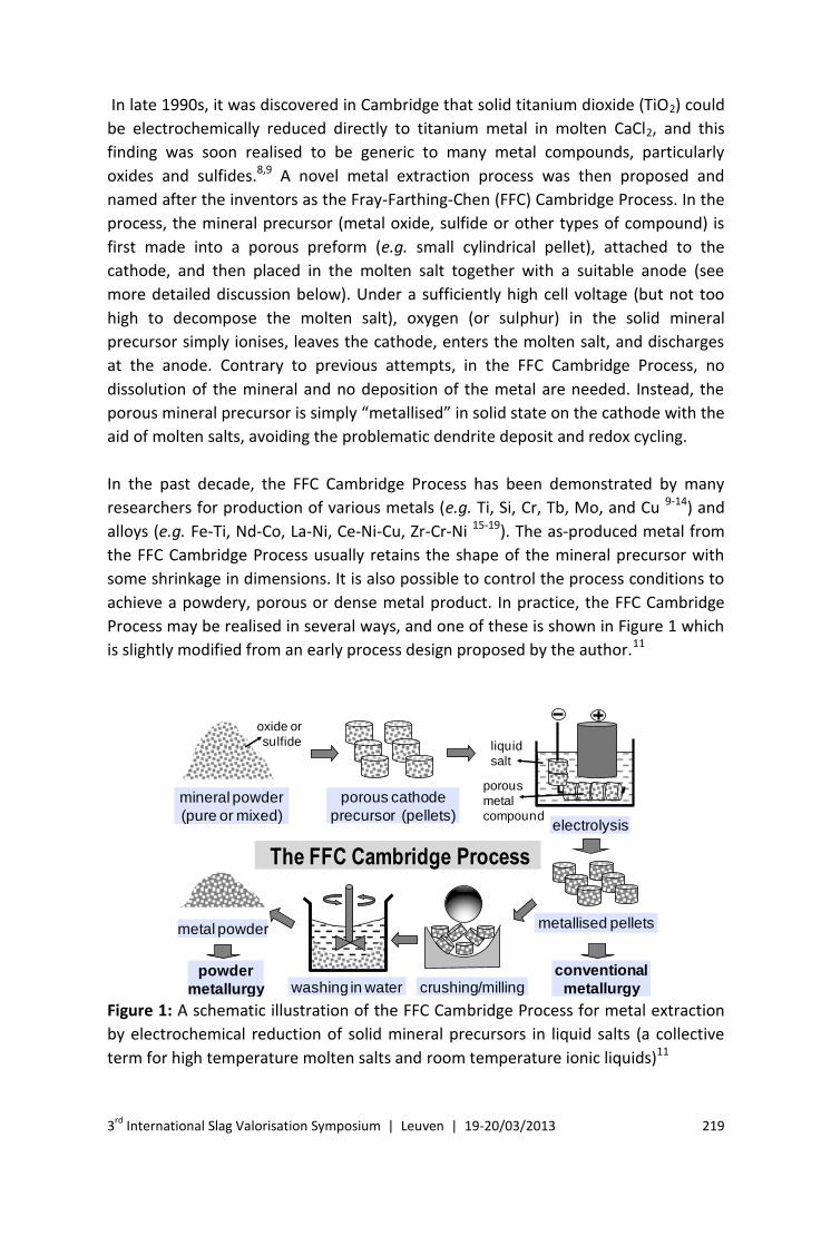
achieve a powdery, porous or dense metal product. In practice, the FFC Cambridge
Process may be realised in several ways, and one of these is shown in Figure 1 which
is slightly modified from an early process design proposed by the author.11
The FFC Cambridge Process
electrolysis
liquid
salt
porous
metal
compound
porous cathode
precursor (pellets)
mineral powder
(pure or mixed)
metallised pellets
conventional
metallurgycrushing/millingwashing in water
metal powder
powder
metallurgy
oxide or
sulfide
Figure 1: A schematic illustration of the FFC Cambridge Process for metal extraction
by electrochemical reduction of solid mineral precursors in liquid salts (a collective
term for high temperature molten salts and room temperature ionic liquids)11
220 3rd
International Slag Valorisation Symposium | Leuven | 19-20/03/2013
Principle
Selection of electrolytes
Like many electrolytic processes, the FFC Cambridge Process takes place in a liquid
electrolyte which is however unique in at least three ways. Firstly, it not only
conducts ionic current in a wide temperature range, but also dissolves and transports
the anions, such as O2-, S2- or Cl-, that are formed in the electrochemical reduction (or
simply electro-reduction or electro-deoxidation) of the solid compound on the
cathode. Secondly, the electrolyte should have no solubility, or as small as possible,
for the compound to be reduced. Last, but not the least, the potential window of the
electrolyte, particularly the cathodic limit, needs to be sufficiently wide so that the
reduction of the solid compound occurs before decomposition of the electrolyte.
Based on earlier research on metal refining,20,12 molten CaCl2 was the first electrolyte
selected and tested for electro-reduction of TiO2 at 950°C.9 This high temperature
approach has been followed in many reported studies on the reduction of various
oxides of refractory metals.10-19 In addition to pure CaCl2, LiCl and BaCl2 are the other
two pure chloride salts capable of accommodating the FFC Cambridge Process for
reduction of metal oxides.7,22,23 This is because these three molten chloride salts can
all dissolve and transport oxide ions (O2-) to significant levels. Mixtures of these and
other chloride salts, such as KCl and NaCl, were also used to achieve electro-
reduction of metal oxides at lower working temperatures.
For electro-reduction of metal sulfides (or electro-desulfidation), both molten CaCl2
and BaCl2 were confirmed to be suitable.13,14,22 An interesting and useful finding from
studies of electro-desulfidation is that the graphite anode, which is a consumable in
electro-reduction of metal oxides, function as an inert anode.13,14 Of greater
importance, it was demonstrated that pure molten NaCl or KCl, and their mixtures,
which have very low solubility for the O2- ion, could also be used for efficient electro-
desulfidation coupled with a graphite inert anode.24
In recent reports, some fluoride salts were applied to support the FFC Cambridge
process for electro-reduction of metal oxides,25 although the toxicity of these salts
may cause environmental concerns if used at large scales. Molten carbonate salts
were also studied with a metallic inert anode.26 Development of the FFC Cambridge
Process in carbonate melts may technically benefit greatly from the historical
interests and development in molten carbonate fuel cells.27-29 Nevertheless, these
environmentally benign melts could only help reduction of oxides of less reactive
metals, such as iron. This is because electro-reduction of carbonate ion (CO32-) to
carbon as a deposit on the cathode occurs at potentials much more positive than
that for the reduction of most reactive metal oxides.26,30
3rd
International Slag Valorisation Symposium | Leuven | 19-20/03/2013 221
Apart from high temperature molten salts, attempts were also made to use either
aqueous electrolytes or ionic liquids for electro-reduction. It is well known that
electro-reduction of solid AgCl to Ag metal can proceed in an aqueous or organic
electrolyte, which is the basis of the widely used Ag/AgCl reference electrode. This
water-insoluble chloride was used as a model compound to study the kinetics and
dynamics of electro-reduction at the compound/metal/electrolyte three-phase
interlines31,32 which will be discussed in details below. A relevant effort succeeded to
electrolytically decompose suspended hematite (Fe2O3) particles to metal iron on the
cathode and oxygen gas on the anode in concentrated NaOH at 114°C.33 It was
further confirmed that when attached to the cathode as a thin film, the fcc Fe3O4
could be electro-reduced to the bcc iron film in 2 M NaOH at room temperature.34
The research effort at room temperatures was extended to using ionic liquids, also
known as room temperature molten salts, for electro-reduction of solid cuprous
chloride to copper nanoparticles.35 It is nevertheless noted that all research attempts
at room temperature have not worked for compounds of refractory metals,
suggesting either or both of thermodynamic and kinetic difficulties.
Thermodynamic and mechanistic considerations
Because of their simpler composition, molten salts can be readily decomposed by
electrolysis to pure elements which can be used as the references for
thermodynamic studies. This is an advantage over electrolysis in aqueous
electrolytes in which parasitic reactions are inevitable. Indeed, molten salt
electrolysis is one of the earliest methods used for determination of thermodynamic
properties of compounds.36 In the FFC Cambridge Process, the compound on the
cathode and the electrolyte composition are defined to sufficient clarity. The anode
can also be assumed (and practically verified) to be either reactive or inert. In the
following discussion, molten CaCl2, TiO2 and Fe2O3 are selected as examples for
thermodynamic calculations using the commercial programme, HSC Chemistry.1
In molten CaCl2, electrolysis of TiO2 or Fe2O3 may bring about electrode reactions as
listed in Table 1, depending on the applied voltage and the reactivity of the anode
material. The anode material may be carbon based (e.g. graphite) or inert such as
SnO2 or the CaRuO3/CaTiO3 composite.37,38 Of the listed reactions, (1) and (7) are
from decomposition of molten CaCl2, and one of these can be used as the reference.
In the literature relevant to the FFC Cambridge Process, most authors used the
electrode potential of (1) as the reference, i.e. Eo (Ca/Ca2+) = 0 V. For the
decomposition reactions of CaCl2(l) Ca(l) + Cl2(g) and CaO Ca(l) + 0.5 O2(g)
at 900°C, the Gibbs free energy values are, ΔGo (CaCl2, l) = 667.413 kJ and ΔGo (CaO) =
486.359 kJ, respectively. Following the equations of ΔGo = nFΔEo (F = 96485 C / mol),
and ΔEo = Eo (anode) - Eo (cathode, reference), it can then be calculated that Eo (Cl-
/Cl2) = 3.459 V, and Eo (O2-/O2) = 2.520 V. Similarly, the electrode potentials for (2),
222 3rd
International Slag Valorisation Symposium | Leuven | 19-20/03/2013
(3) and (6) can be calculated by coupling with (1) and (6) to establish the respective
overall cell reactions. For example, for (5b), the overall reaction can be written as 2
CaO + C 2Ca(l) + CO2(g) with ΔGo = 576.679 kJ and ΔEo = 1.494 V. If CaO
dissociates completely to Ca2+ and O2- before saturation in molten CaCl2, it is
reasonable to assume Eo (Ca/Ca2+) Eo (Ca/CaO). Thus, Eo (C/CO2) = 1.494 V.
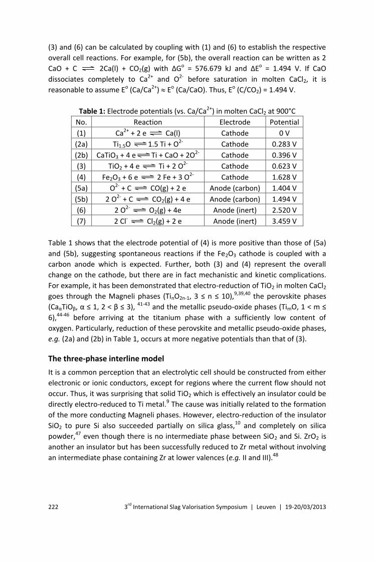
Table 1: Electrode potentials (vs. Ca/Ca2+) in molten CaCl2 at 900°C
No. Reaction Electrode Potential
(1) Ca2+ + 2 e Ca(l) Cathode 0 V
(2a) Ti1.5O 1.5 Ti + O2- Cathode 0.283 V
(2b) CaTiO3 + 4 e Ti + CaO + 2O2- Cathode 0.396 V
(3) TiO2 + 4 e Ti + 2 O2- Cathode 0.623 V
(4) Fe2O3 + 6 e 2 Fe + 3 O2- Cathode 1.628 V
(5a) O2- + C CO(g) + 2 e Anode (carbon) 1.404 V
(5b) 2 O2- + C CO2(g) + 4 e Anode (carbon) 1.494 V
(6) 2 O2- O2(g) + 4e Anode (inert) 2.520 V
(7) 2 Cl- Cl2(g) + 2 e Anode (inert) 3.459 V
Table 1 shows that the electrode potential of (4) is more positive than those of (5a)
and (5b), suggesting spontaneous reactions if the Fe2O3 cathode is coupled with a
carbon anode which is expected. Further, both (3) and (4) represent the overall
change on the cathode, but there are in fact mechanistic and kinetic complications.
For example, it has been demonstrated that electro-reduction of TiO2 in molten CaCl2
goes through the Magneli phases (TinO2n-1, 3 ≤ n ≤ 10),9,39,40 the perovskite phases
(CaαTiOβ, α ≤ 1, 2 < β ≤ 3), 41-43 and the metallic pseudo-oxide phases (TimO, 1 < m ≤
6),44-46 before arriving at the titanium phase with a sufficiently low content of
oxygen. Particularly, reduction of these perovskite and metallic pseudo-oxide phases,
e.g. (2a) and (2b) in Table 1, occurs at more negative potentials than that of (3).
The three-phase interline model
It is a common perception that an electrolytic cell should be constructed from either
electronic or ionic conductors, except for regions where the current flow should not
occur. Thus, it was surprising that solid TiO2 which is effectively an insulator could be
directly electro-reduced to Ti metal.9 The cause was initially related to the formation
of the more conducting Magneli phases. However, electro-reduction of the insulator
SiO2 to pure Si also succeeded partially on silica glass,10 and completely on silica
powder,47 even though there is no intermediate phase between SiO2 and Si. ZrO2 is
another an insulator but has been successfully reduced to Zr metal without involving
an intermediate phase containing Zr at lower valences (e.g. II and III).48
3rd
International Slag Valorisation Symposium | Leuven | 19-20/03/2013 223
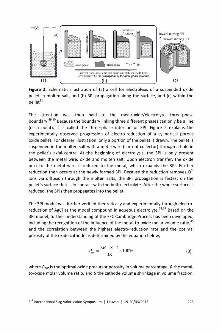
Figure 2: Schematic illustration of (a) a cell for electrolysis of a suspended oxide
pellet in molten salt, and (b) 3PI propagation along the surface, and (c) within the
pellet11
The attention was then paid to the meal/oxide/electrolyte three-phase
boundary.49,50 Because the boundary linking three different phases can only be a line
(or a point), it is called the three-phase interline or 3PI. Figure 2 explains the
experimentally observed progression of electro-reduction of a cylindrical porous
oxide pellet. For clearer illustration, only a portion of the pellet is drawn. The pellet is
suspended in the molten salt with a metal wire (current collector) through a hole in
the pellet’s axial centre. At the beginning of electrolysis, the 3PI is only present
between the metal wire, oxide and molten salt. Upon electron transfer, the oxide
next to the metal wire is reduced to the metal, which expands the 3PI. Further
reduction then occurs at the newly formed 3PI. Because the reduction removes O2-
ions via diffusion through the molten salts, the 3PI propagation is fastest on the
pellet’s surface that is in contact with the bulk electrolyte. After the whole surface is
reduced, the 3PIs then propagates into the pellet.
The 3PI model was further verified theoretically and experimentally through electro-
reduction of AgCl as the model compound in aqueous electrolyte.31,32 Based on the
3PI model, further understanding of the FFC Cambridge Process has been developed,
including the recognition of the influence of the metal-to-oxide molar volume ratio,45
and the correlation between the highest electro-reduction rate and the optimal
porosity of the oxide cathode as determined by the equation below,
3 1100%
3opt
R SP
R
(3)
where Popt is the optimal oxide precursor porosity in volume percentage, R the metal-
to-oxide molar volume ratio, and S the cathode volume shrinkage in volume fraction.
(a) (b)
A
V
inward moving 3PI
outward moving 3PI
oxide phase metal phase
curr
ent
coll
ecto
r
3PI
metallised
surface
current rises, passes the maximum and stabilises with time, accompanied by the propagation of the three-phase interline.
(c)

224 3rd
International Slag Valorisation Symposium | Leuven | 19-20/03/2013
This simple relationship, called the PRS model, agrees very well with experimental
studies of the electro-reduction of TiO2, Ta2O5 and SiO2 in molten chloride salts.49
Practice
In the past decade, great efforts and significant progresses have been made world-
wide in fundamental research and commercial development of the FFC Cambridge
Process.6,7,50 In practice, various electrode, cell and process designs and analytic
methods have been applied to study the process. These are highlighted as follow.
Process control
Temperature: The FFC Cambridge Process was first demonstrated in both the three-
electrode cell (with a Ti metal pseudo-reference electrode) and two-electrode cell in
molten CaCl2 under argon. The melting point of CaCl2 is about 780°C, depending on
the purity. Thus, the working temperature of molten CaCl2 was varied between 800°C
and 950°C. Further increasing the temperature causes salt evaporation,22 although
CaCl2 would not boil below 1600°C. Again, faster electro-reduction was observed at
higher temperatures. It is worth mentioning that the process should not be operated
under air or vacuum to avoid (1) contamination of the product by oxygen, and in
some cases, nitrogen, or (2) evaporation of the chloride salts. The salt vapour can
condense in, and block the gas outlet of the reactor, and is also very hygroscopic and
corrosive to laboratory equipment.
Voltage: In the two-electrode cell, the electrolysis was typically carried out under
constant voltage control, although constant current control was also used for
understanding electrode reactions.51 The upper limit of the electrolysis voltage was
set to be high enough to reduce the metal oxide (compound), but also to avoid
decomposition of the molten salt. For molten CaCl2, the voltage control follows the
data in Table 1. The electrolysis rate increases with the cell voltage, but the current
efficiency does not always follow the same trend. Another factor affecting the
current efficiency is electronic conduction which is common in molten salts
containing dissolved metal and/or cyclic redox reactions, and increases with
voltage.52-54 In the following discussion, the focus is on molten CaCl2 which is mostly
used in research as reported in the existing literature.
Electronic conduction was found to be more serious in molten CaCl2 than in for
example, molten BaCl2.22 This difference is at least partly due to CaCl2 being more
hygroscopic than BaCl2, which means that there is likely more CaO in molten CaCl2
than BaO in molten BaCl2 after thermal drying as explained here. In general, chlorides
of alkali and alkaline earth elements are hygroscopic in nature, and require pre-
3rd
International Slag Valorisation Symposium | Leuven | 19-20/03/2013 225
drying the salt granules before melting. This can be achieved by a three stage heating
programme for treatment of typically up to 1 kg of the salt granules. Firstly, quickly
raise the temperature (e.g. 10°C/min) to 150°C in air to evaporate most physically
absorbed water in ca. 1 h. Secondly, slowly heat to 270°C (e.g. 0.2°C) to remove
chemically bonded or hydrated water for up to 5 h. Finally, place the salt in the
sealed reactor that is purged with argon, and increase the temperature (e.g.
10°C/min) to 700°C for ca. 1 h before melting.22,55
Moisture in molten salts is redox active and can contribute to lowering the current
efficiency and also cause hydrolysis such as CaCl2 + H2O CaO + 2 HCl(g). Careful
thermal drying as introduced above can help to remove a great amount of water in
the salt, but is practically challenging to achieve completion in air or even an inert
gas. More complete drying may be achieved by thermal drying under the HCl gas,
which is not preferred consider the safety regulations in laboratories nowadays. Pre-
electrolysis (e.g. 2.5~2.8 V and 1~5 h in 1 kg of molten CaCl2 under argon) has been
applied in the author’s work to achieve satisfactory removal of the moisture without
compromising safety. The added benefit of pre-electrolysis is that it can also remove
other redox active impurities such as the Mg2+ ions with a nickel cathode.56
Because electro-reduction of metal oxides always discharges O2- from the cathode
into the molten salt, a small amount of CaO from hydrolysis is not a problem. It can
in fact help avoid anodic discharge of Cl- ions in the initial period of electrolysis.
However, too high a concentration of CaO can cause a large back ground current,
particularly when the cathode was mostly metallised, due to CaO decomposing at a
lower voltage than CaCl2, see Table 1. The optimal initial CaO concentration should
correlate with the maximum current passing through the cell during electrolysis. It
obviously depends on the total amounts of metal oxide on the cathode and of the
molten CaCl2 in the cell. An effective practice is to start with a CaO concentration as
low as possible, and allow the electrolysis to generate CaO by discharging some the
Cl- ions in the initial period of electrolysis of the metal oxide.
Time: Electrolysis time is an important variable for control of the oxygen content in
the produced metals. For electrolysis of ca. 1~3 g of pellets of metal oxides, the time
was typically less than 10 h for less reactive metals, such as Cr and Fe, but much
longer for Ti and Nb. Because of the relatively high background current, a longer time
of electrolysis means a lower current efficiency. For example, for electrolysis of a 1~2
g pellet of Cr2O3, 6 h electrolysis at 2.8 V and 950°C is sufficient to achieve low
oxygen content (< 2000 ppm) with the current efficiency being higher than 75%. 11 A
similar experiment for TiO2 would take a much longer time with the current
efficiency dropping to below 15%.41,57 An important theoretical development in
electro-reduction is the correlation of the electrolysis efficiency (speed) with the
226 3rd
International Slag Valorisation Symposium | Leuven | 19-20/03/2013
metal-to-oxide molar volume ratio and the cathode structure (porosity).45,49 This
correlation requires a porosity of ca. 68% in a TiO2 pellet of 2~3 mm in thickness to
achieve fastest reduction rate, which was well verified experimentally.
Cell and electrode
The first demonstration of the FFC Cambridge Process used both the three-electrode
cell (for electrochemical analysis with a Ti metal pseudo-reference electrode) and
two electrode-cell (for demonstration and also preparation of sufficient amounts of
products) in molten CaCl2 at 800 ~ 950°C under argon. Several materials have been
used for fabrication of the electro-reduction cell, including titanium, graphite, steel
(stainless) and alumina. Silica is not recommended because of its vulnerability to
chemical attack by, for example, CaO and Ca metal at elevated temperatures.
Titanium is a highly effective material due to its ability as a getter to lower the
oxygen content in the reactor, which is needed for reducing oxides of highly reactive
metals, such as Ti and Zr. However, graphite which also can react with oxygen offers
a satisfactory and much cheaper alternative for making reactive metals. Alumina
crucibles were used successfully to produce less reactive metals, e.g. Cr and Si.11,47
Stainless steel crucibles were used to producing Cr11 and can be used repeatedly. The
main concern is product contamination by Fe, Ni, and, to a lesser degree, Cr which
are discharged into the molten salt from the stainless steel crucible.
In early electro-reduction experiments,9 the working electrode or cathode was a TiO2
thin layer coated titanium foil, or small porous cylindrical pellets of compacted TiO2
powder. The counter electrode or anode was a graphite rod whilst the molten salt
was contained in a titanium cup (crucible). In the follow-on studies since 2000, many
changes have been made to these early experimental settings. However, the pellet
design remains the choice for electro-reduction of many metal oxides and sulfides in
the two-electrode cell. Fabrication of the pellet from the oxide powder in laboratory
research is usually via either die-pressing or slip casting, followed by sintering at
elevated temperatures (e.g. 900 ~ 1000°C for TiO2). Polymeric binder may be used to
increase the strength of the as-formed pellet for handling and can be burned out
during sintering. The pellet cathode design enabled a recent in-situ investigation of
electrolysis of TiO2 by synchrotron diffraction, revealing very valuable information.58
In addition to benefits to electro-reduction, the selection of pellets based cathode is
to take advantage of the fact that pelletising technologies are widely used in
commercial products related with, for example, minerals, biomass and medicines.
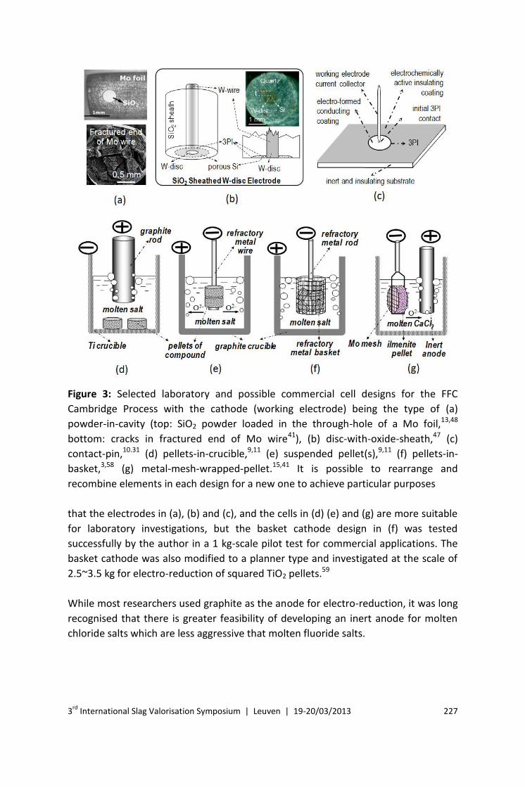
Attachment of the metal compound (oxide or sulfide) to the cathodic current
collector can be achieved via several ways, and some are illustrated in Figure 3. Note
3rd
International Slag Valorisation Symposium | Leuven | 19-20/03/2013 227
Figure 3: Selected laboratory and possible commercial cell designs for the FFC
Cambridge Process with the cathode (working electrode) being the type of (a)
powder-in-cavity (top: SiO2 powder loaded in the through-hole of a Mo foil,13,48
bottom: cracks in fractured end of Mo wire41), (b) disc-with-oxide-sheath,47 (c)
contact-pin,10.31 (d) pellets-in-crucible,9,11 (e) suspended pellet(s),9,11 (f) pellets-in-
basket,3,58 (g) metal-mesh-wrapped-pellet.15,41 It is possible to rearrange and
recombine elements in each design for a new one to achieve particular purposes
that the electrodes in (a), (b) and (c), and the cells in (d) (e) and (g) are more suitable
for laboratory investigations, but the basket cathode design in (f) was tested
successfully by the author in a 1 kg-scale pilot test for commercial applications. The
basket cathode was also modified to a planner type and investigated at the scale of
2.5~3.5 kg for electro-reduction of squared TiO2 pellets.59
While most researchers used graphite as the anode for electro-reduction, it was long
recognised that there is greater feasibility of developing an inert anode for molten
chloride salts which are less aggressive that molten fluoride salts.
228 3rd
International Slag Valorisation Symposium | Leuven | 19-20/03/2013
Prospect
The FFC Cambridge Process is now being developed for production of titanium and
tantalum at scales of commercial significance by spin-out companies of the
University of Cambridge that have been specially established for commercialisation
of the FFC Cambridge Process.50,59 Pending on commercial development, the process
has shown a wide spectrum of opportunities to produce various energy related
materials at low costs. For example, there is an increasing trend of using electro-
reduction to reprocess spent nuclear fuels containing dominantly oxides of uranium
and other actinides in molten salts.23,62-64 Another example is the electro-synthesis of
hydrogen storage alloy powders directly from the respective oxide mixtures.15,60,61 A
particularly interesting finding is that it is possible to electro-reduce TiO2 to Ti2O in
the form of nano-powders that serve very well as a highly active and CO-immune
support of Pt catalyst for electro-oxidation of methanol or CO.65
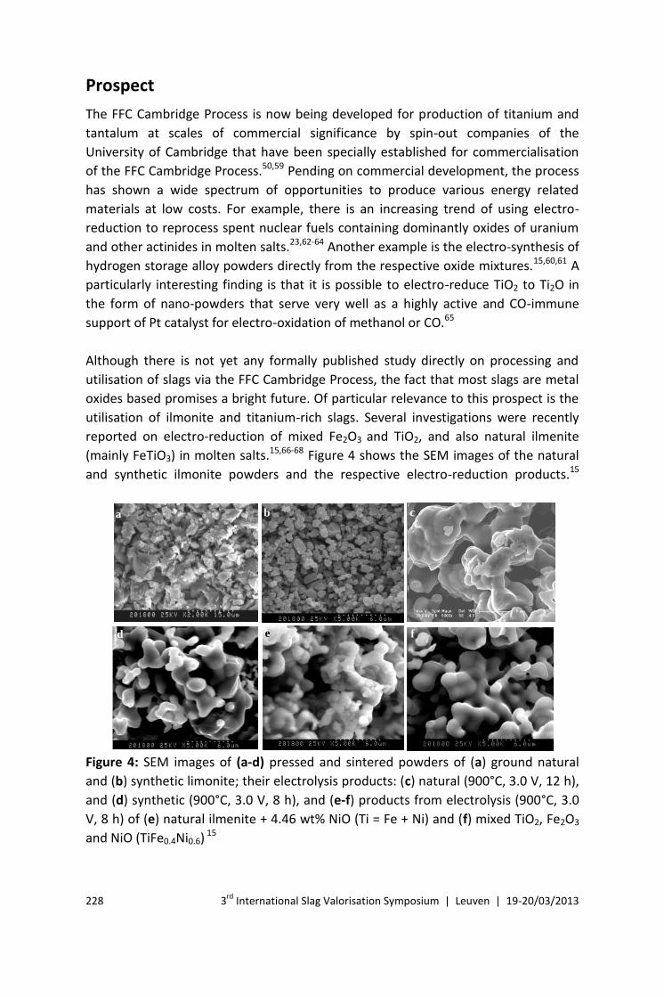
Although there is not yet any formally published study directly on processing and
utilisation of slags via the FFC Cambridge Process, the fact that most slags are metal
oxides based promises a bright future. Of particular relevance to this prospect is the
utilisation of ilmonite and titanium-rich slags. Several investigations were recently
reported on electro-reduction of mixed Fe2O3 and TiO2, and also natural ilmenite
(mainly FeTiO3) in molten salts.15,66-68 Figure 4 shows the SEM images of the natural
and synthetic ilmonite powders and the respective electro-reduction products.15
a b c
d e f
Figure 4: SEM images of (a-d) pressed and sintered powders of (a) ground natural
and (b) synthetic limonite; their electrolysis products: (c) natural (900°C, 3.0 V, 12 h),
and (d) synthetic (900°C, 3.0 V, 8 h), and (e-f) products from electrolysis (900°C, 3.0
V, 8 h) of (e) natural ilmenite + 4.46 wt% NiO (Ti = Fe + Ni) and (f) mixed TiO2, Fe2O3
and NiO (TiFe0.4Ni0.6) 15
3rd
International Slag Valorisation Symposium | Leuven | 19-20/03/2013 229
Particularly for hydrogen storage, Ni was introduced into the product by addition of a
suitable amount of NiO powder to the ilmenite powder before sintering. XRD
analyses confirmed the electro-reduction products to be of the expected TiFe or
TiFexNiy (x + y = 1) alloys.
It was observed that electro-reduction of ilmenite (or mixed Fe2O3 and TiO2) started
from the formation of pure iron, on which TiO2 was reduced later to form directly the
alloy.15,66-68 According to this understanding, the energy released from the alloy
formation should have contributed to lowering the cell voltage in comparison with
that for the reduction of pure TiO2. The actual energy consumption for reducing
natural ilmenite was 14.4 kWh/kg-alloy at 3.0 V for 8 h, even though about 60%
oxygen in the cathode was removed in the first hour.15 Oxygen contents in products
from electrolysis for 15 h reached below 300 ppm in Fe-rich products, and below
1000 ppm for Ti-rich products.67 In comparison, the lowest energy consumption for
electro-reduction of TiO2 under similar conditions, to Ti with an oxygen content of
3900 ppm was 25 kWh/kg-Ti.45
When changing the composition of the electrolytic Fe-Ti alloys, it was found that the
products (after electric arc melting into ingots) reached highest hardness when Fe
content was in the range from 15 to 50 wt%. These very hard products were also
very brittle and should not be used for structural purposes. At other compositions,
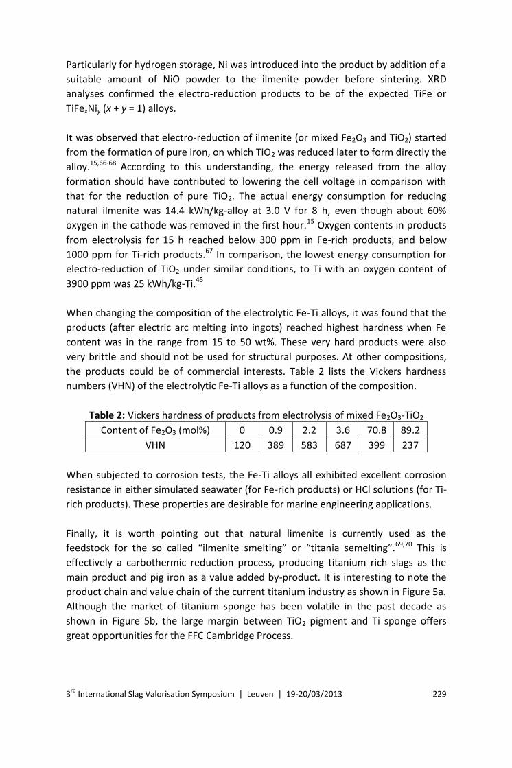
the products could be of commercial interests. Table 2 lists the Vickers hardness
numbers (VHN) of the electrolytic Fe-Ti alloys as a function of the composition.
Table 2: Vickers hardness of products from electrolysis of mixed Fe2O3-TiO2
Content of Fe2O3 (mol%) 0 0.9 2.2 3.6 70.8 89.2
VHN 120 389 583 687 399 237
When subjected to corrosion tests, the Fe-Ti alloys all exhibited excellent corrosion
resistance in either simulated seawater (for Fe-rich products) or HCl solutions (for Ti-
rich products). These properties are desirable for marine engineering applications.
Finally, it is worth pointing out that natural limenite is currently used as the
feedstock for the so called “ilmenite smelting” or “titania semelting”.69,70 This is
effectively a carbothermic reduction process, producing titanium rich slags as the
main product and pig iron as a value added by-product. It is interesting to note the
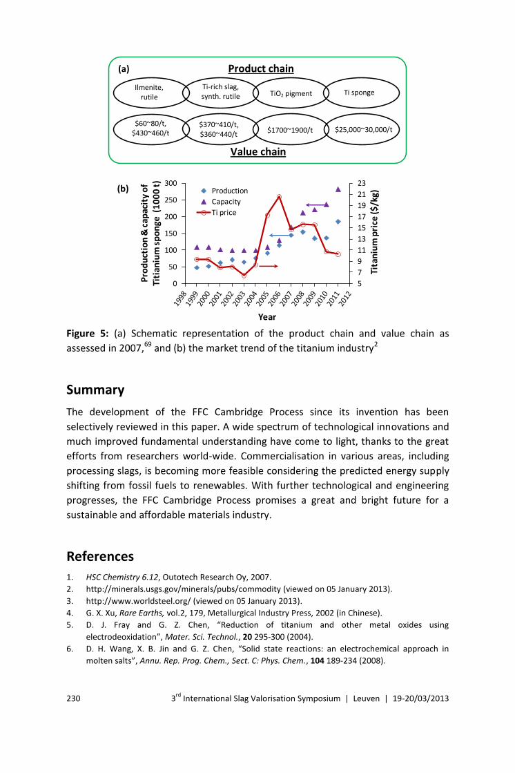
product chain and value chain of the current titanium industry as shown in Figure 5a.
Although the market of titanium sponge has been volatile in the past decade as
shown in Figure 5b, the large margin between TiO2 pigment and Ti sponge offers
great opportunities for the FFC Cambridge Process.
230 3rd
International Slag Valorisation Symposium | Leuven | 19-20/03/2013
Product chain
Ilmenite, rutile
Ti-rich slag, synth. rutile TiO2 pigment Ti sponge
$60~80/t, $430~460/t
$370~410/t, $360~440/t
$1700~1900/t $25,000~30,000/t
Value chain
5
7
9
11
13
15
17
19
21
23
0
50
100
150
200
250
300
Tita
niu
m p
rice
($/k
g)
Pro
du
ctio
n &
cap
acit
y o
f Ti
tian
ium
sp
on
ge (
10
00
t)
Year
Production
Capacity
Ti price
(a)
(b)
Figure 5: (a) Schematic representation of the product chain and value chain as
assessed in 2007,69 and (b) the market trend of the titanium industry2
Summary
The development of the FFC Cambridge Process since its invention has been
selectively reviewed in this paper. A wide spectrum of technological innovations and
much improved fundamental understanding have come to light, thanks to the great
efforts from researchers world-wide. Commercialisation in various areas, including
processing slags, is becoming more feasible considering the predicted energy supply
shifting from fossil fuels to renewables. With further technological and engineering
progresses, the FFC Cambridge Process promises a great and bright future for a
sustainable and affordable materials industry.
References
1. HSC Chemistry 6.12, Outotech Research Oy, 2007.
2. http://minerals.usgs.gov/minerals/pubs/commodity (viewed on 05 January 2013).
3. http://www.worldsteel.org/ (viewed on 05 January 2013).
4. G. X. Xu, Rare Earths, vol.2, 179, Metallurgical Industry Press, 2002 (in Chinese).
5. D. J. Fray and G. Z. Chen, “Reduction of titanium and other metal oxides using
electrodeoxidation”, Mater. Sci. Technol., 20 295-300 (2004).
6. D. H. Wang, X. B. Jin and G. Z. Chen, “Solid state reactions: an electrochemical approach in
molten salts”, Annu. Rep. Prog. Chem., Sect. C: Phys. Chem., 104 189-234 (2008).
3rd
International Slag Valorisation Symposium | Leuven | 19-20/03/2013 231
7. D. J. Fray, “Novel methods for the production of titanium”, Int. Mater. Rev., 53 317-325 (2008).
8. D. J. Fray, T. W. Farthing and Z. Chen, “Removal of oxygen from metal oxides and solid solutions
by electrolysis in a fused salt”, Patent, WO99064638, (1999).
9. G. Z. Chen, D. J. Fray and T. M. Farthing, “Direct electrochemical reduction of titanium dioxide to
titanium in molten calcium chloride”, Nature, 407 361-364 (2000).
10. T. Nohira, K. Yasuda and Y. Ito, “Pinpoint and bulk electrochemical reduction of insulating silicon
dioxide to silicon”, Nat. Mater., 2 397-401 (2003).
11. G. Z. Chen, E. Gordo and D. J. Fray, “Direct electrolytic preparation of chromium powder”, Metall.
Mater. Trans. B, 35 223-233 (2004).
12. D. H. Wang, G. H. Qiu, X. B. Jin, X. H. Hu and G. Z. Chen, “Electrochemical metallization of solid
terbium oxide”, Angew. Chem. Int. Ed., 45 2384-2388 (2006).
13. G. M. Li, D. H. Wang, X. B. Jin and G. Z. Chen, “Electrolysis of solid MoS2 in molten CaCl2 for Mo
extraction without emission”, Electrochem. Commun., 9 1951-1957 (2007).
14. X. L. Ge, X. D. Wang and S. Seetharaman, “Copper extraction from copper ore by electro-
reduction in molten CaCl2-NaCl”, Electrochim. Acta, 54 4397-4402 (2009).
15. M. Ma, D. H. Wang, X. H. Hu, X. B. Jin and G. Z. Chen, “A direct electrochemical route from
ilmenite to hydrogen-storage ferrotitanium alloys”, Chem. Eur. J., 12 5075-5081 (2006).
16. Y. Zhu, D. H. Wang, X. H. Hu, X. B. Jin and G. Z. Chen, “More affordable electrolytic LaNi5-type
hydrogen storage powders”, Chem. Commun., 2515-2517 (2007).
17. A. M. Abdelkader, D. J. S. Hyslop, A. Cox and D. J. Fray, “Electrochemical synthesis and
characterization of a NdCo5 permanent magnet”, J. Mater. Chem., 20 6039-6049 (2010).
18. J. J. Peng, Y. Zhu, D. H. Wang, X. B. Jin and G. Z. Chen, “Direct and low energy electrolytic co-
reduction of mixed oxides to zirconium-based multi-phase hydrogen storage alloys in molten
salts”, J. Mater. Chem., 19 2803-2809 (2009).
19. X. Kang, Q. Xu, X. M. Yang and Q. S. Song, “Electrochemical synthesis of CeNi4Cu alloy from the
mixed oxides and in situ heat treatment in a eutectic LiCl-KCl melt”, Mater. Lett., 64 2258-2260
(2010).
20. R. G. Ward and T. P. Hoar, “The electrolytic removal of oxygen, sulphur, selenium, and tellurium
from molten copper”, J. Inst. Met., 90 6-12 (1961).
21. T. H. Okabe, M. Nakamura, T. Oishi and K. Ono, “Electrochemical Deoxidation of Titanium”,
Metall. Trans. B, 24 449-455 (1993).
22. G. Z. Chen and D. J. Fray, “Cathodic refining in molten salts: removal of oxygen, sulfur and
selenium from static and flowing molten copper”, J. App. Electrochem., 31 155-164 (2001).
23. J.-M. Hur, S.-C. Lee, S.-M. Jeong, C.-S. Seo, “Electrochemical reduction of TiO2 in molten LiCl-
Li2O”, Chem. Lett., 36 1028-1029 (2007).
24. T. Wang, H. P. Gao, X. B. Jin, H. L. Chen, J. J. Peng and G. Z. Chen, “Electrolysis of solid metal
sulfide to metal and sulfur in molten NaCl-KCl”, Electrochem. Commun., 13 1492-1495 (2011).
25. M. Gibilaro, J. Pivato, L. Cassayre, L. Massot, P. Chamelot and P. Taxil, “Direct electro-reduction
of oxides in molten fluoride salts”, Electrochim. Acta, 56 5410-5415 (2011).
26. H. Y. Yin, D. Y. Tang, H. Zhu, Y. Zhang and D. H. Wang, “Production of iron and oxygen in molten
K2CO3–Na2CO3 by electrochemically splitting Fe2O3 using a cost affordable inert anode”,
Electrochem. Commun., 13 1521-1524 (2011).
27. E. Antolini, “The stability of molten carbonate fuel cell electrodes: A review of recent
improvements”, App. Energy, 88 4274-4293 (2011).
28. M. Farooque and H.C. Maru, “Carbonate fuel cells: Milliwatts to megawatts”, J. Power Sources,
160 827-834 (2006).
29. M. Cassir and C. Belhomme, “Technological applications of molten salts: the case of the molten
carbonate fuel cell”, Plasmas & Ions, 2 3-15 (1999).
30. N. J. Siambun, H. Mohamed, D. Hu, D. Jewell, Y. K. Beng and G. Z. Chen, “Utilisation of carbon
dioxide for electro-carburisation of mild steel in molten carbonate salts”, J. Electrochem. Soc.,
158 H1117-H1124 (2011).
232 3rd
International Slag Valorisation Symposium | Leuven | 19-20/03/2013
31. Y. Deng, D. H. Wang, W. Xiao, X. B. Jin, X. H. Hu and G. Z. Chen, “Electrochemistry at
conductor/insulator/electrolyte three-phase interlines: A thin layer model”, J. Phys. Chem. B, 109
14043-14051 (2005).
32. W. Xiao, X. B. Jin, Y. Deng, D. H. Wang and G. Z. Chen, “Three-phase interlines electrochemically
driven into insulator compounds: A penetration model and its verification by electroreduction of
solid AgCl”, Chem. Eur. J., 13 604-612 (2007).
33. B. Y. Yuan, O. E. Kongstein and G. M.Haarberg, “Electrowinning of iron in aqueous alkaline
solution using a rotating cathode”, J. Electrochem. Soc., 156 D64-D69 (2009).
34. Z. He, R. V. Gudavarthy, J. A. Koza and J. A. Switzer, “Room-temperature electrochemical
reduction of epitaxial magnetite films to epitaxial iron films”, J. Am. Chem. Soc., 133 12358-
12361 (2011).
35. L. P. Yu, H. J. Sun, J. He, D. H. Wang, X. B. Jin and G. Z. Chen, “Electro-reduction of solid cuprous
chloride to copper nanoparticles in an ionic liquid”, Electrochem. Commun., 9 1374-1381 (2007).
36. M. Faraday, “Experimental researches in electricity. Seventh series”, Phil. Trans. R. Soc. Lond.,
123 507-522 (1833).
37. R. Barnett, K. T. Kilby and D. J. Fray, “Reduction of Tantalum Pentoxide Using Graphite and Tin-
Oxide-Based Anodes via the FFC-Cambridge Process”, Metall. Mater. Trans. B, 40 150-157 (2009).
38. S. Q. Jiao, L. L. Zhang, H. M. Zhu and D. J. Fray, “Production of NiTi shape memory alloys via
electro-deoxidation utilizing an inert anode”, Electrochim. Acta, 55 7016-7020 (2010).
39. K. Dring, R. Dashwood and D. Inman, “Voltammetry of titanium dioxide in molten calcium
chloride at 900 oC” J. Electrochem. Soc., 152 E104-E113 (2005).
40. F.C. Walsh and R.G.A. Wills, “The continuing development of Magnéli phase titanium sub-oxides
and Ebonex® electrodes”, Electrochim. Acta, 55 6342-6351 (2010).
41. K. Jiang, X. H. Hu, M. Ma, D. H. Wang, G. H. Qiu, X. B. Jin and G. Z. Chen, ““Perovskitization”-
assisted electrochemical reduction of solid TiO2 in molten CaCl2”, Angew. Chem. Int. Ed., 45 428-
432 (2006).
42. C. Schwandt and D. J. Fray, “Determination of the kinetic pathway in the electrochemical
reduction of titanium dioxide in molten calcium chloride”, Electrochim. Acta, 51 66-76 (2005).
43. M. A. Pena and J. L. G. Fierro, “Chemical structures and performance of perovskite oxides”,
Chem. Rev., 101 1981-2017 (2001).
44. G. Z. Chen, D. J. Fray and T. W. Farthing, “Cathodic deoxygenation of the alpha case on titanium
and alloys in molten calcium chloride”, Metall. Mater. Trans. B, 32 1041-1052 (2001).
45. W. Li, X. B. Jin, F. L. Huang and G. Z. Chen, “Metal-to-oxide molar volume ratio: The overlooked
barrier to solid-state electro-reduction and a green bypass through recyclable NH4HCO3”, Angew.
Chem. Int. Ed., 49 3203-3206 (2010).
46. T. B. Massalski, H. Okamoto, P. R. Subramanian and L. Kacprzak (eds), Binary Alloy Phase
Diagrams, 2nd ed., Vol. 3, 2924-2927, ASM International, Materials Park, 1990.
47. X. B. Jin, P. Gao, D. H. Wang, X. H. Hu and G. Z. Chen, “Electrochemical preparation of silicon and
its alloys from solid oxides in molten calcium chloride”, Angew. Chem., Int. Ed., 43 733-736
(2004).
48. J. J. Peng, K. Jiang, W. Xiao, D. H. Wang, X. B. Jin and G. Z. Chen, “Electrochemical conversion of
oxide Precursors to consolidated Zr and Zr-2.5Nb tubes”, Chem. Mater., 20 7274-7280 (2008).
49. H. L. Chen, Y. Zeng, W. Li, J. J. Peng, X. B. Jin and G. Z. Chen, “A PRS model for accurate prediction
of the optimal solid oxide cathode structure for the preparation of metals in molten chlorides”,
Electrochem. Commun., 26 33-36 (2013).
50. D. J. Fray, “Exploring Novel Uses of Molten Salts”, ECS Trans., 50 3-13 (2012).
51. D. J. S. Hyslop, A. M. Abdelkader, A. Cox and D. J. Fray, “Utilization of Constant Current
Chronopotentiometry to Synthesize a Co–Cr AlloyElectrochemical Synthesis and Engineering”, J.
Electrochem. Soc., 157 E111-E115 (2010).
52. G. M. Haarberg, K. S. Osen, R. J. Heus, and J. J. Egan, “Electronic conduction and electron
mobilities in molten NaCI-Na solutions”, J. Electrochem. Soc., 137 2777 (1990).
3rd
International Slag Valorisation Symposium | Leuven | 19-20/03/2013 233
53. A. Sterten, P. A. Solli, “Cathodic process and cyclic redox reactions in aluminium electrolysis
cells”, J. App. Electrochem., 25 809-816 (1995).
54. G. H. Qiu, K. Jiang, M. Ma, D. H. Wang, X. B. Jin and G. Z. Chen, “Roles of cationic and elemental
calcium in the electro-reduction of solid metal oxides in molten calcium chloride”, Z.
Naturforsch., 62a 292–302 (2007).
55. G. Z. Chen and D. J. Fray, “Voltammetric studies of the oxygen-titanium binary system in molten
calcium chloride”, J. Electrochem. Soc., 149 E455-E467 (2002).
56. W. Xiao, X. B. Jin, Y. Deng, D. H. Wang, X. H. Hu and G. Z. Chen, “Electrochemically Driven Three-
Phase Interlines into Insulator Compounds: Electroreduction of Solid SiO2 in Molten CaCl2”,
ChemPgysChem, 7 1750 – 1758 (2006).
57. C. Schwandt, D. T. L. Alexander and D. J. Fray, “The electro-deoxidation of porous titanium
dioxide precursors in molten calcium chloride under cathodic potential control”, Electrochim.
Acta, 54 3819-3829 (2009).
58. R. Bhagat, D. Dye, S. L. Raghunathan, R. J. Talling, D. Inman, B. K. Jackson, K. K. Rao and R. J.
Dashwood, “In situ synchrotron diffraction of the electrochemical reduction pathway of TiO2”,
Acta Mater., 58 5057-5062 (2010).
59. C. Schwandt, G. R. Doughty and D. J. Fray, “The FFC-Cambridge Process for Titanium Metal
Winning”, Key Eng. Mater, 436 13-25 (2010).
60. Y. Zhu, D. H. Wang, M. Ma, X. H. Hu, X. B. Jin and G. Z. Chen, “More affordable electrolytic LaNi5-
type hydrogen storage powders”, Chem. Comm., 2515-2517 (2007).
61. J. J. Peng, Y. Zhu, D. H. Wang, X. B. Jin and G. Z. Chen, “Direct and low energy electrolytic co-
reduction of mixed oxides to zirconium-based multi-phase hydrogen storage alloys in molten
salts”, J. Mater. Chem., 19 2803-2809 (2009).
62. Y. Sakamura, M. Kurata and T. Inoue, “Electrochemical reduction of UO2 in molten CaCl2 or LiCl”,
J. Electrochem. Soc., 153 D31-D39 (2006).
63. E. Y. Choi, J. W. Lee, J. J. Park, J. M. Hur, J. K. Kim, K. Y. Jung and S. M. Jeong, “Electrochemical
reduction behavior of a highly porous SIMFUEL particle in a LiCl molten salt”, Chem. Eng. J., 207
514-520 (2012).
64. http://www.refine.eng.ed.ac.uk/
65. X. X. Shi, X. B. Jin, W. Xiao, X. Hou, H. L. Chen and G. Z. Chen, “Processing nanomaterials in
molten salts: Partially electrometallized TiO2 as Pt support for enhanced catalytic oxidation of CO
and CH3OH”, Chem. Eur. J., 17 8562-8567 (2011).
66. S. Tan, T. Ors, M. K. Aydınol, T. Ozturk and I. Karakaya, “Synthesis of FeTi from mixed oxide
precursors”, J. Alloys Compd., 475 368–372 (2009).
67. G. M. Li, X. B. Jin, D. H. Wang and G. Z. Chen, “Affordable electrolytic ferrotitanium alloys with
marine engineering potentials”, J. Alloys Compd., 482 320-327 (2009).
68. M. Panigrahi,, A. Iizuka, E. Shibata and T. Nakamura, “Electrolytic reduction of mixed (Fe, Ti)
oxide using molten calcium chloride electrolyte”, J. Alloys Compd., 550 545-552 (2013).
69. C. V. G. K. Murty, R. Upadhyay and S. Asokan, “Electro smelting of ilmenite for production of TiO2
slag – Potential of india as a global player”, in Proceedings of International Ferro-Alloys Congress
XI (Infacon XI), New Delhi, India, 18-21 February, 2007.
http://www.pyrometallurgy.co.za/InfaconXI/078.pdf (Viewed on 10 Feb. 2013)
70. P. C. Pistorius, “Titania slag smelting and calcination of crude zinc oxide: examples of processing
under thermodynamic and kinetic constraints”, in Proceedings 2nd
Int. Slag Valorisation Symp. –
Transition to Sustainable Materials Management, Edited by P. T. Jones, Y. Pontikes, J. Elsen, O.
Cizer, L. Boehme, T. V. Gerven, D. Geysen, M. Guo, B. Blanpain, Leuven, Belgium, 18-20 April,
2011. http://www.slag-valorisation-symposium.eu/2011/images/papers/s4_3_pistorius.pdf
(Viewed on 10 Feb. 2013)