the flat dilatometer test (dmt): design applications and recent developments p. monaco, s. marchetti...
TRANSCRIPT

The Flat Dilatometer Test (DMT):Design Applications
and Recent Developments
P. Monaco, S. Marchetti & G. TotaniUniversity of L'Aquila, Italy

ORIGINAL PAPERMARCHETTI S. (1980). In Situ Tests by Flat Dilatometer.J. Geotech. Engrg. Div. ASCE, 106(GT3), 299-321
STANDARDSASTM D6635-01 (2001). Standard Test Method for Performing the Flat Plate Dilatometer.EUROCODE 7 – Geotechnical Design – Part 2: Ground Investigation and Testing. EN 1997-2:2007
SOA REPORTTC16 (2001). The Flat Dilatometer Test (DMT) in Soil Investigations. May 2001, 41 pp. Reprint in Proc. 2nd Int. Conf. on Flat Dilatometer, Washington D.C., 7-48
INTERNETwww.marchetti-dmt.it biblio site (download papers)
KEY DMT REFERENCES

BLADE
FLAT DILATOMETER (DMT)
FLEXIBLE MEMBRAN
E

Push force provided by penetrometer or drill rig
DMT blade Push rods (e.g. CPT) Pneumatic-electrical cable Control unit Pneumatic cable Gas tank MEMBRANE EXPANSION
GENERAL LAYOUT of DMT
p0 & p1 readings at 20 cm depth intervals

CLAY, SILT, SAND – But can cross through GRAVEL layers 0.5 m
Soils from VERY SOFT to VERY STIFF (upper limit is push capacity of rig)
Clays: Cu = 2-4 to 1000 kPa (marls)
Moduli: up to 400 MPa
SOILS that can be TESTED by DMT

Basic DMT reduction formulae (TC16 2001)
p0 Corrected First Reading p0 = 1.05 (A - ZM + A) - 0.05 (B - ZM - B) p1 Corrected Second Reading p1 = B - ZM - B ID Material Index ID = (p1 - p0) / (p0 - u0) KD Horizontal Stress Index KD = (p0 - u0) / 'v0 ED Dilatometer Modulus ED = 34.7 (p1 - p0) K0 Coeff. Earth Pressure in Situ K0,DMT = (KD / 1.5)0.47 - 0.6
OCR Overconsolidation Ratio OCRDMT = (0.5 KD)1.56 cu Undrained Shear Strength cu,DMT = 0.22 'v0 (0.5 KD)1.25 Friction Angle safe,DMT = 28° + 14.6° log KD - 2.1° log2
KD ch Coefficient of Consolidation ch,DMTA 7 cm2
/ tflex kh Coefficient of Permeability kh = ch w / Mh (Mh K0 MDMT) Unit Weight and Description (see chart in TC16 2001)
MDMT = RM ED if ID 0.6 RM = 0.14 + 2.36 log KD if ID 3 RM = 0.5 + 2 log KD if 0.6 < ID < 3 RM = RM,0 + (2.5 - RM,0) log KD
with RM,0 = 0.14 + 0.15 (ID - 0.6) if KD > 10 RM = 0.32 + 2.18 log KD
M Vertical Drained Constrained Modulus
if RM < 0.85 set RM = 0.85 u0 Equilibrium Pore Pressure u0 = p2 = C - ZM + A

DMT results
KD = 2 NC clay
ID
M Cu
KD
soil type(clay, silt,
sand)
common use shape similar to OCR helps understand history of deposit

In most cases DMT used to determine common geotechnical design parameters
Experience has shown undrained shear strength Cu and constrained modulus M by DMT generally accurate and dependable for design
Comparisons at several research sites indicate quite good agreement between profiles of Cu and M by DMT and reference values by other tests ( see TC16 2001)
Design using soil parameters

Comparisons Cu DMT vs. Cu reference
Research Site Bothkennar
(UK)
Research SiteFucino (Italy)
AGI (1991)
Nash et al. (1992)

M (MPa)
0
10
20
30
0 20 40 60 80
z (m
)
M by DMT vs. M by high quality oedometersOnsøy (Norway)
Comparisons MDMT vs. Mreference
Lacasse (1986)
MDMT
M back-calculated
M by DMT vs. M back-calculated from local vertical strains measured under Treporti full-scale test embankment (Italy)
Marchetti et al. (2006)

by Boussinesq
Settlement predictionNo. 1 DMT application
Classic linear elastic 1-D approach – or 3-D with E 0.8 MDMT (similar predictions)
Settlement under working loads (Fs 2.5-3.5)

0
50
100
150
200
250
300
350
400
0 50 100 150 200 250 300 350 400
DMT-calculated settlement (mm)
Me
as
ure
d s
ett
lem
en
t (m
m)
Hayes 1990 Skiles & Townsend 1994 Marchetti 1997 Didaskalou 1999 Marchetti et al. 2004 Mayne 2005
DMT/measured=0.5
DMT/measured=2
DMT/measured=1ALL SOILS
0
50
100
150
200
250
300
350
400
0 50 100 150 200 250 300 350 400
DMT-calculated settlement (mm)
Me
as
ure
d s
ett
lem
en
t (m
m)
Hayes 1990 Skiles & Townsend 1994 Marchetti 1997 Didaskalou 1999 Marchetti et al. 2004 Mayne 2005
DMT/measured=0.5
DMT/measured=2
DMT/measured=1ALL SOILS
Summary of comparisonsDMT-predicted vs. observed settlements
Monaco et al. (2006)
Large No. of case histories good agreement for wide range of soil types, settlements, footing sizes
Average ratio DMT-calculated/observed settlement 1.3
Band amplitude (ratio max/min) < 2 i.e. observed settlement within ± 50
% from DMT-predicted

Experience suggests DMT well suited to detect BENEFITS of SOIL IMPROVEMENT due to its high sensitivity to changes of stresses/density in soil
Several comparisons of CPT and DMT before/after compactionSchmertmann et al. (1986), Jendeby (1992) increase in MDMT after compaction of sand 2 increase in qc (CPT)Pasqualini & Rosi (1993) ...
Compaction control

Ratio MDMT /qc before/after compaction of a loose sand fill (Jendeby 1992)
DMT vs. CPT before/after compaction BEFORE AFTERBEFORE AFTERBEFORE AFTER MDMT
MDMTqcqc

DMT-KD method Verify if an OC clay slope contains ACTIVE (or old QUIESCENT) SLIP SURFACES(Totani et al. 1997)
0 2
10
20
30
D
1. SLIDING
K (DMT) 2
3. RECONSOLIDATION(NC STATE)
4. INSPECT D PROFILEK
2. REMOULDING
Detecting slip surfaces in clay slopes
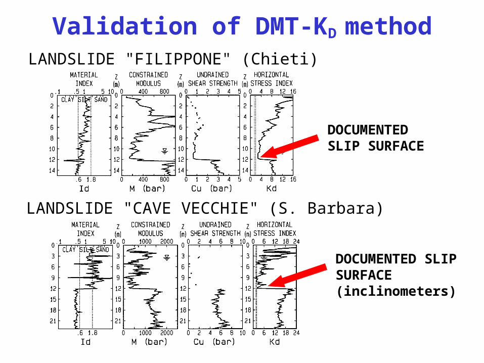
LANDSLIDE "FILIPPONE" (Chieti)
LANDSLIDE "CAVE VECCHIE" (S. Barbara)
DOCUMENTED SLIP SURFACE
DOCUMENTED SLIP SURFACE(inclinometers)
Validation of DMT-KD method

DMT for LIQUEFACTION Correlations for evaluating Cyclic
Resistance Ratio CRR from KD developed in past 2 decades, stimulated by:
Key element supporting well-based CRR-KD correlation: ability of KD to reflect aging in sands (1st order of magnitude influence on liquefaction) + sensitivity of KD to non-textbook OCR crusts in sands
– Sensitivity of KD to factors known to increase liquefaction resistance: Stress History, prestraining/aging, cementation, structure …
– Correlation KD – Relative Density
– Correlation KD – In situ State Parameter

Summary + latest version CRR-KD correlation see Monaco et al. (2005 ICSMGE Osaka)
Magnitude M = 7.5 – Clean sand
0
0.1
0.2
0.3
0.4
0.5
0 2 4 6 8 10
0.5
0.4
0.3
0.2
0.1
0 0 2 4 6 8 10
KD
CSRor
CRR
Robertson & Campanella 1986
Marchetti 1982
M = 7.5
NO LIQUEFACTION
LIQUEFACTION
Reyna & Chameau 1991
Range of curves derived from CPT
Range of curves derived from SPT
New tentativeCRR-KD curveMonaco et al. 2005
0
0.1
0.2
0.3
0.4
0.5
0 2 4 6 8 10
0.5
0.4
0.3
0.2
0.1
0 0 2 4 6 8 10
0
0.1
0.2
0.3
0.4
0.5
0 2 4 6 8 10
0.5
0.4
0.3
0.2
0.1
0 0 2 4 6 8 10
KD
CSRor
CRR
Robertson & Campanella 1986
Marchetti 1982
M = 7.5
NO LIQUEFACTION
LIQUEFACTION
Reyna & Chameau 1991
Range of curves derived from CPTRange of curves derived from CPT
Range of curves derived from SPTRange of curves derived from SPT
New tentativeCRR-KD curveMonaco et al. 2005
New tentativeCRR-KD curveMonaco et al. 2005
Curves for evaluating CRR from KD
(Seed & Idriss 1971 simplified procedure)

DMT for DESIGN ofLATERALLY LOADED PILES
Robertson et al. (1987)Marchetti et al. (1991)
2 methods recommended for deriving P-y curves for laterally loaded piles from DMT (single pile, 1st time monotonic loading)
Mortaiolo (Italy)
NC soft clay
Mortaiolo (Italy)
NC soft clay
Independent validations 2 methods provide similar predictions, in very good agreement with observed full-scale pile behaviour

DMT for DESIGN ofDIAPHRAGM WALLS
Tentative correlation for deriving the coefficient of subgrade reaction Kh for design of multi-propped diaphragm walls from MDMT
Indications on how to select input moduli for FEM analyses (PLAXIS Hardening Soil model) based on MDMT
g.l.
sH
L
g.l.g.l.
ssHH
LL
Monaco & Marchetti (2004 – ISC'2 Porto)

Subgrade compaction control
MDMT acceptance profile(max always found at 25-26
cm)
Bangladesh Subgrade Compaction Case History90 km Road Rehabilitation Project
Acceptance MDMT profile fixed and used as alternative/fast acceptance tool for quality control of subgrade compaction, with only occasional verifications by originally specified methods (Proctor, CBR, plate)

• 2 receivers spaced 0.5 m
• Vs determined from delay arrival of impulse from 1st to 2nd receiver (same hammer blow)
• Signal amplified + digitized at depth
• Vs measured every 0.5 m
Combination S +
DMT
Seismic Dilatometer (SDMT)
Hepton 1988Martin & Mayne 1997, 1998 ... (Georgia Tech, USA)

Validation of Vs by SDMT
Comparison of Vs profiles by SDMTand by other tests
Fucino research site(Italy)
SDMT (2004)
AGI (1991)
SCPT Cross Hole SASW

Vs (m/s)
SHEAR WAVEVELOCITY
SDMT results
SDMT profiles at the site of Fiumicino (Italy)
SDMT accurate and highly repeatable Vs (in addition to usual DMT results)

SDMT small strain modulus G0 from Vsworking strain modulus MDMT
(settlements) Tentative methods to derive in situ G- curves by
SDMT Two points help in selecting the G- curve
In situ G- decay curves by SDMT
Mayne (2001)Ishihara (2001)
HARA (1973) YOKOTA et al. (1981) TATSUOKA (1977) SEED & IDRISS (1970) ATHANASOPOULOS (1995) CARRUBBA & MAUGERI (1988)
0.05 to 0.1%
HARA (1973) YOKOTA et al. (1981) TATSUOKA (1977) SEED & IDRISS (1970) ATHANASOPOULOS (1995) CARRUBBA & MAUGERI (1988)
0.05 – 0.1 %
Maugeri (1995)

SDMT 2 parallel independent evaluations of CRR from VS e KD
(Seed & Idriss 1971 simplified procedure)
SDMT for LIQUEFACTION
Andrus & Stokoe (2000)Andrus et al. (2004)
Monaco et al. (2005)ICSMGE Osaka
CRR from Vs CRR from KD
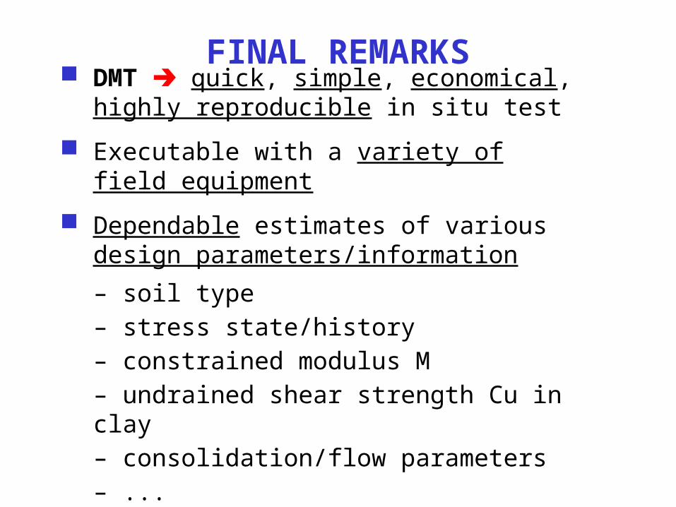
DMT quick, simple, economical, highly reproducible in situ test
Executable with a variety of field equipment
Dependable estimates of various design parameters/information
– soil type– stress state/history– constrained modulus M– undrained shear strength Cu in clay– consolidation/flow parameters– ...
FINAL REMARKS

Variety of design applications
Most effective vs. common penetration tests when settlements/deformations important for design (e.g. strict specs or need to decide: piles or shallow ?)
SDMT accurate measurements of Vs (and G0) + usual DMT results – greatly enhances DMT capability
FINAL REMARKS
Special thanks to Allan McConnell (IGS)