the florida emergency medical services communications plan · division of telecommunications the...
TRANSCRIPT
Division of Telecommunications
The Florida Emergency Medical
Services Communications Plan
Volume 1 (Fourth Edition)

DEPARTMENT OF MANAGEMENT SERVICES DIVISION OF TELECOMMUNICATIONS 4030 ESPLANADE WAY, SUITE 180.01 TALLAHASSEE, FLORIDA 32399-0950
MEMORANDUM: TO: FLORIDA EMS COMMUNICATIONS PLAN, VOLUME 1 RECIPIENTS
FROM: CHARLES GHINI, DIRECTOR DIVISION OF TELECOMMUNICATIONS DATE: March 17, 2011
SUBJECT: FLORIDA EMERGENCY MEDICAL SERVICES COMMUNICATIONS PLAN, VOLUME 1 Fourth Edition The Florida Emergency Medical Services Communications Plan, Volume 1 has been revised as a Fourth Edition and is now available online at:
http://dms.myflorida.com/suncom/public_safety_bureau/radio_communications/radio_communication_plans.
This edition includes updates, clarifications, and new text. On each revised page, a vertical bar ("|") in the left margin identifies lines of text that have been modified since the previous issue of that page. Re-formatting or other minor irregularities corrected that resulted in no substantive change to the information are not identified. Specifically, the changes include; but are not limited to the following:
Regionalized MEDCOM Updated narrowbanding deadline from 2018 to 2013 Volume 2 hardcopy or electronic format in permitted vehicles Consistent reference to minimum notification distance for LMC coverage Incorporated APCO/NPSTC channel naming standard (ANS 1.104.1-2010) Incorporated references to additional communications plans and guides §5.2.3 added to define LMC communications coverage contour Re-organized §4.7.1 and §5.3 to remove duplication Introduced Project 25 requirements for digital radio equipment Deleted non-essential information in Mobile Data section Replaced Appendix A with Plans and Committees functional relationship chart Revised Appendix B to include references to multiple communications policies Deleted non-essential acronyms and definitions

Page 2
March 17, 2011
This edition is being made available to all organizations and individuals identified per Section 1.3 of the Plan. To ensure that you receive future revisions for Volume I and Volume II, please verify that the name and email address on file with the Department of Health, Bureau of Emergency Medical Services is correct. I thank the personnel in the Division of Telecommunications, the Bureau of Emergency Medical Services, the EMS Communications Committee, the Agency of Health Care Administration (AHCA), and others that provided input toward this revision. More than ever, this plan is intended to meet the expectations of EMS agencies on a statewide basis. If you have any comments or questions regarding this edition, please contact Carlton Wells at (850) 922-7426 or via email at [email protected].
CG:cww:lm: EMS Comm Plan, Volume 1 Fourth Edition Final.doc

EMS Communications Plan, Vol. 1
Fourth Edition 2
Table of Contents
1.0 INTRODUCTION ............................................................................................................... 6
1.1 Executive Summary ......................................................................................................... 6
1.2 Legislative Background.................................................................................................... 8
1.3 Wording ............................................................................................................................ 9
1.4 Plan Revision Procedure .................................................................................................. 9
2.0 ADMINISTRATIVE INFORMATION ............................................................................ 11
2.1 Division of Telecommunications (DivTel) .................................................................... 11
2.2 Federal Communications Commission .......................................................................... 12
2.3 Florida – Region 9 Plan for 800 MHz Public Safety Radio Communications .............. 15
2.4 Florida – Region 9 Plan for 700 MHz Public Safety Radio Communications .............. 16
2.5 Florida 700 MHz Public Safety Interoperability Channel Plan ..................................... 16
2.6 Florida Ambulance Deployment Plan ............................................................................ 16
2.7 Florida Public Health and Medical Communications Plan ............................................ 17
2.8 Florida Mutual Aid Channel (MA-FLA) ....................................................................... 17
2.9 Federal Aviation Administration .................................................................................... 17
2.10 NIMS, SAFECOM, Interoperability Continuum, SCIP, NIFOG, and FIFOG .............. 17
2.11 Communications Approvals ........................................................................................... 19
Figure 1 – DivTel Approval Process ..................................................................................... 22
3.0 DESIGN CRITERIA FOR EMS COMMUNICATIONS ................................................. 23
3.1 General ........................................................................................................................... 23
3.2 Citizen Access ................................................................................................................ 23
3.3 Vehicle Dispatch and Response (VDR) ......................................................................... 23
3.4 Local Medical Coordination (LMC) .............................................................................. 24
3.5 Countywide Medical Coordination (CMC).................................................................... 24
3.6 Proprietary Trunked Radio Systems .............................................................................. 25

EMS Communications Plan, Vol. 1
Fourth Edition 3
3.7 Statewide Medical Coordination (SMC) ........................................................................ 25
3.8 Local Scene Coordination (LSC) ................................................................................... 25
3.9 Statewide-Scene Coordination (SSC) ............................................................................ 26
3.10 Medical Resource Coordination (MRC) ........................................................................ 26
3.11 Biomedical Telemetry .................................................................................................... 26
3.12 Interagency/Mutual Aid Coordination ........................................................................... 26
3.13 Back-up Communications .............................................................................................. 27
3.14 Telephone Interconnection ............................................................................................. 28
4.0 FREQUENCY PLAN ........................................................................................................ 29
4.1 Background .................................................................................................................... 29
4.2 Channel Allotment Principles ........................................................................................ 29
4.3 Vehicle Dispatch and Response Channels ..................................................................... 31
4.4 Countywide Medical Coordination Channels ................................................................ 33
4.5 Local Medical Coordination (LMC) Channels .............................................................. 33
4.6 Medical Resource Coordination (MRC) Channels ........................................................ 33
4.7 Statewide Medical Coordination (SMC) Channel ......................................................... 34
Table 4-1 – Wide-Area and Statewide Interagency/Mutual-Aid Frequencies ...................... 41
Table 4-2 – Florida Countywide MED Channel & CTCSS Allotments ............................... 43
5.0 SYSTEM REQUIREMENTS ............................................................................................ 45
5.1 General ........................................................................................................................... 45
5.2 Communications Coverage Contour .............................................................................. 46
5.3 Statewide Medical Coordination (SMC) ........................................................................ 47
5.4 SMC Radio Station ........................................................................................................ 50
5.5 SMC Mobile Radios in Permitted Vehicles ................................................................... 50
5.6 Local Medical Coordination (LMC) .............................................................................. 51
5.7 Radios in Permitted Vehicles ......................................................................................... 51

EMS Communications Plan, Vol. 1
Fourth Edition 4
5.8 Vehicle Dispatch and Response (VDR) ......................................................................... 52
5.9 Medical Resource Coordination (MRC) ........................................................................ 52
5.10 Crew Alert Paging .......................................................................................................... 52
5.11 Telephone Interconnection ............................................................................................. 53
5.12 Biomedical Telemetry .................................................................................................... 53
5.13 Radio Frequency Control Stations ................................................................................. 53
5.14 FCC Narrowband Mandate Below 512 MHz ................................................................. 54
5.15 MED Channel Frequencies ............................................................................................ 54
Table 5-1 – Specific MED Channel Assignments for Florida Acute Care Facilities ............ 55
6.0 EQUIPMENT REQUIREMENTS..................................................................................... 61
6.1 Minimum Performance Standards .................................................................................. 61
6.2 Base/Repeater Station Radio Equipment – Analog........................................................ 61
6.3 Mobile Radio Equipment – Analog ............................................................................... 62
6.4 Portable Radio Equipment – Analog .............................................................................. 64
6.5 Base/Repeater Station Radio Equipment – Digital ........................................................ 66
6.6 Mobile Radio Equipment – Digital ................................................................................ 67
6.7 Portable Radio Equipment – Digital .............................................................................. 69
6.8 Mobile/Portable Channelization ..................................................................................... 71
7.0 CONCEPTS OF MOBILE DATA COMMUNICATIONS .............................................. 73
7.1 General ........................................................................................................................... 73
7.2 SAFECOM Statement of Requirements ........................................................................ 73
7.3 Mobile Data Communication Coverage Reliability ....................................................... 74
7.4 Mobile Data Security ..................................................................................................... 74
7.5 Mobile Data Computer Minimum Recommended Specifications ................................. 75
7.6 Wireless LAN Technologies & Standards ..................................................................... 75
APPENDIX A – FUNCTIONAL RELATIONSHIPS WITH PLANS AND COMMITTEES .... 76

EMS Communications Plan, Vol. 1
Fourth Edition 5
APPENDIX B – STATE AGENCIES AND LOCAL EMS POLICIES ...................................... 77
1.0 PUBLIC SAFETY MUTUAL AID CHANNEL (MA-FLA) ........................................ 78
2.0 MINIMIZING RISK OF OBSOLESCENCE FOR RADIO EQUIPMENT .................. 82
3.0 RADIO EQUIPMENT REPLACEMENT POLICY...................................................... 86
4.0 RADIO FREQUENCY BUY OUT POLICY ................................................................. 88
5.0 CAPITOL BUILDING ROOFTOP ANTENNA POLICY ............................................ 89
6.0 NEW AND EXISTING STATE OWNED FACILITIES ROOFTOP ANTENNA
POLICY .................................................................................................................................... 90
APPENDIX C – PUBLIC SAFETY RADIOS FOR AIRCRAFT UTILIZATION ..................... 91
APPENDIX D – ACRONYMS FOR EMERGENCY MEDICAL SERVICES
COMMUNICATIONS ................................................................................................................. 95
APPENDIX E – GLOSSARY OF COMMUNICATIONS TERMS ............................................ 99

EMS Communications Plan, Vol. 1
Fourth Edition 6
1.0 INTRODUCTION
1.1 Executive Summary
The Division of Telecommunications (DivTel) is mandated by Chapter 401.015, Florida Statutes,
(F.S.) "to develop a statewide system of regional emergency medical telecommunications."
Further, Chapter 401.024, F.S., requires further that "no emergency medical telecommunications
system shall be established or present systems expanded without prior approval of the
Department of Management Services".
In 1975, the first Emergency Medical Services (EMS) Communications Plan (Plan) was
implemented and the approval system necessary to fulfill these statutory obligations was
established. In conjunction with Federal funding made available from 1973 through 1981 by the
United States Congress through the EMS Systems Act, the first Plan enabled implementation of
many EMS radio systems throughout the state in the Ultra High Frequency (UHF) radio
frequency band. Experience gained during the intervening years, changes in technological
approaches, and changes in EMS operational needs have necessitated EMS Communications
Plan revisions. The Plan is kept current through an active change program. Any corrections,
additions, or constructive suggestions for improvement of its content should be submitted as
appropriate.
By means of this Plan, and funding made available through the State EMS Grants Program, new
directions and enhancements in the statewide EMS telecommunications system have been
established. In an effort to maintain these improvements each user of this Plan is encouraged to
send questions and comments on any matter that this Plan does or should contain to:
EMS Communications
Division of Telecommunications
4030 Esplanade Way
Tallahassee, FL 32399-0950
Phone (850) 922-7426
FAX (850) 414-8324
The Plan is organized into two volumes. Volume I contains the general, administrative, and
regulatory information needed by the managers of organizations involved in EMS operations. It
further defines the broad concepts and goals of EMS communications within Florida.
Volume II contains the statewide radio frequency allocations as well as operational information
for day-to-day EMS communications system operations. Volume II is formatted as a field
manual to be carried as a standard reference on each permitted vehicle, either in hardcopy or
electronic format.

EMS Communications Plan, Vol. 1
Fourth Edition 7
Within Volume I, the "Administrative Information" section includes general information on
DivTel, the Federal Communications Commission (FCC) rules, radio frequencies, and frequency
coordination requirements; the Florida Region 9 Plan for Public Safety Radio Communications;
and the DivTel EMS communications approval procedures. The "Concepts" section defines the
fundamental modes of EMS communications and system capabilities referred to throughout both
volumes. The "Frequency Plan" section defines the methodology controlling the use of radio
frequencies within the statewide EMS system. Within the "System Requirements" and
"Equipment Requirements" sections are the specific requirements by which the approval of EMS
communications system implementation or expansion will be determined. Lastly, is the section
pertaining to “Mobile Data Communications,” this section provides information to assist in the
design and/or implementation of a mobile data system employed in an EMS communications
system.
Volume II includes an "Operations" section which provides FCC operational rules,
recommended operating practices, a user-oriented description of radio theory with consideration
in Public Safety radio bands and concepts established in EMS communications. The remainder
of Volume II is devoted to the detailed radio frequencies and/or specific numerical allocations
for EMS agencies or hospital Emergency Departments within Florida. Additionally, interstate
allocations for adjacent counties in Georgia and Alabama are included and the geographic
coordinates for hospitals within Florida.
Throughout the development of this Plan, we have attempted to keep the new editions as short
and as straightforward as possible. We believe this approach will improve the usefulness of this
Plan and facilitate future revisions. We have accordingly limited the statewide requirements on
EMS communications systems and equipment to the minimum level that we believe necessary to
ensure the effectiveness of essential modes of EMS communications.
We wish to acknowledge that preparation, publication, and distribution of this Plan has been in
cooperation with the Department of Health, Bureau of Emergency Medical Services. We believe
this mutual effort has been and will continue to be highly successful in improving EMS
throughout Florida.
We further express our appreciation to the many individuals both within and outside the DivTel,
particularly, the EMS Communications Committee, who have contributed their time, effort, and
ideas toward making this Plan a meaningful and useful document. It is only through such
interaction and exchange of ideas on a continuing basis that this Plan will serve to satisfy the
original legislative intent "that a statewide system of regional emergency medical
telecommunications be developed whereby maximum use of existing radio channels is achieved
in order to more effectively and rapidly provide emergency medical service to the general
population."
State of Florida
Division of Telecommunications
EMS Communications

EMS Communications Plan, Vol. 1
Fourth Edition 8
1.2 Legislative Background
The Division of Telecommunications (DivTel), previously the State Technology Office,
Department of Management Services, was established by the 1969 Florida Legislature for the
purpose of planning and coordinating all telecommunications services for State agencies and
political subdivisions, as specified in Section 282.702, F.S. DivTel is charged to provide the
state of Florida and its operating agencies with an integrated, effective, and efficient statewide
telecommunications system(s) that will satisfy operational needs. Since its inception in 1970,
this office has received additional responsibilities and authority that specifically relate to Public
Safety telecommunications at the local level.
Section 282.7101, Florida Statutes, originally enacted by the legislature in 1972, mandated
DivTel to develop a statewide system of regional law enforcement communications "whereby
maximum efficiency in the use of existing radio channels is achieved in order to more effectively
deal with the apprehension of criminals and the prevention of crime generally". This statute
requires approval by the DivTel prior to implementation of new systems or expansion of existing
systems. This additional authority includes the law enforcement community at county and
municipal levels.
In 1973, the Florida Legislature enacted Chapter 401, Part I, F.S., the EMS Telecommunications
Act, relating to emergency medical service telecommunications; providing for the establishment
and regulation of EMS telecommunications; mandating the DivTel to formulate and implement a
Plan encompassing each medical service entity within the state; and listing those items to be
included in such a plan. Like Section 282.7101, F.S., this statute requires approval by the DivTel
prior to implementation of new communications systems or the expansion of existing systems.
In 1992, the Florida Legislature amended Chapter 395 (Hospital Licensing and Regulation) that
created Section 395.1031, F.S. This section specifically addresses EMS communications at
licensed hospitals with an emergency department. The requirements of Section 395.1031, F.S.,
and DivTel authority therein is consistent with that specified under Chapter 401, Part I, F.S., the
EMS Telecommunications Act.
In 1974, the Florida Legislature enacted the Florida Emergency Telephone Act. The act states
that "it is the intent of the legislature to establish and implement a cohesive statewide emergency
telephone number 9-1-1 plan..." and directs DivTel to prepare such a plan. Included is a mandate
to all public agencies to assist in the preparation of the plan and to comply with the requirements
of the developed plan. Further, the act directs that no 9-1-1 systems be established or expanded
without prior approval of DivTel.
Since all aspects of the 9-1-1 system development, implementation, and approval are provided
for in the 9-1-1 Emergency Telephone Number Plan, this EMS Communications Plan does not
include, other than conceptually, provisions for the 9-1-1 "citizen access" portion of emergency
medical services operations.

EMS Communications Plan, Vol. 1
Fourth Edition 9
1.3 Wording
The concept of word usage and intended meaning that has been adhered to in preparing this Plan
is as follows:
A “Shall” has been used only when application of a procedure is mandatory.
A “Should” has been used only when application of a procedure is recommended.
A “May” and "need not" have been used only when application of a procedure is
optional.
A “Will” has been used only to indicate futurity, never to indicate any degree of
requirement for application of a procedure.
1.4 Plan Revision Procedure
A major goal in the development and distribution of this Plan has been to establish an effective
revision procedure to ensure that all necessary information and requirements regarding EMS
Communications are promptly made available to affected EMS organizations. This section
defines the revision transmittal procedure, and formatting style for both new and revised pages.
A copy of Volume I and accompanying copy of Volume II is made available and/or distributed
to each EMS agency licensed by the Department of Health, Bureau of Emergency Medical
Services, and each hospital licensed by the Agency for Health Care Administration that has an
emergency department within the state of Florida. Additionally, where appropriate other Public
Safety agencies and radio vendors affecting EMS may also obtain a copy.
1.4.1 Revision Transmittal Procedure
New or revised information to both Volumes I and II will be prepared by DivTel following
appropriate changes to the Plan and/or affected database information. With each edition of either
Volume will be transmitted with a REVISION MEMORANDUM that defines the essence of the
revisions included in the new edition.
1.4.2 Revision Format
A. Cover Page: With any revision to Volume I, the cover page will be replaced with a new
page showing the latest edition of the most recent revision. With any revision to Volume
II, the cover page will be replaced with a new page showing the latest date of the most
recent revision.
B. Revised Pages: On each page, a vertical bar ("│") in the left margin will be used to
identify any lines of text that have been modified since the previous edition. Subsequent
editions will use the vertical bar for only the most recent change affecting the new
edition.

EMS Communications Plan, Vol. 1
Fourth Edition 10
C. New Pages: Similar to revised pages; new pages will be indicated by a vertical bar ("│")
in the left margin from the top to the bottom of the page. Only on rare occasions will
revising every line of an existing page cause this indication.
D. Deleted Pages: If substantive, all deleted pages or major sections will be recognized by
the REVISION MEMORANDUM and will have been removed from the respective Plan
completely.
END OF SECTION 1.0

EMS Communications Plan, Vol. 1
Fourth Edition 11
2.0 ADMINISTRATIVE INFORMATION
2.1 Division of Telecommunications (DivTel)
In fulfilling a wide range of telecommunications services and regulatory responsibilities, DivTel
is organized into several sections that encompass a multitude of disciplines associated with the
telecommunications systems throughout the state. Some examples of the these responsibilities
are to oversee activities related to the statewide telephone system (SUNCOM), directory
assistance, telephone services invoicing, the 9-1-1 emergency telephone number system, wire
line data communications, and publication of the State of Florida Telephone Directory. Other
areas within DivTel are primarily involved with activities related to land mobile, microwave,
satellite radio systems, and radio frequency coordination, as well as closed circuit television,
audio, and security/surveillance systems. These responsibilities include the overall engineering
and regulation of all state agency telecommunications in the above areas, and for law
enforcement telecommunications at the county, municipal and non-government organization
levels.
Specifically with respect to EMS communications, DivTel is mandated in accordance with
Chapter 401, Part I, F.S., with roles and responsibilities further defined by the interagency
agreement with the Florida Department of Health, Bureau of Emergency Medical Services.
DivTel is responsible for regulatory direction and communications engineering services to
county, municipal, and non-government EMS organizations that encompass the following wide
range of disciplines:
A. Communications System Analysis: Includes the survey and analysis for new or existing
communications systems to determine specific requirements in the engineering and
operational aspects of system performance, system recommendations, procurement
schedules, and preliminary budgetary estimates.
B. Communications Planning: Closely related to communication system analysis, planning
services include formal planning on state, regional, county, municipal and non-
government levels. Within the planning framework, engineering and operational system
requirements are defined and translated into present and future equipment and system
needs.
C. Grant Writing Assistance: Assistance in the preparation of grant applications is provided
when requested by the EMS agency. For larger communications systems analysis and
planning prior to detailed system design must be utilized before a application is
submitted. Smaller and/or simpler communications systems may request a budgetary
estimate. A budgetary estimate is a “quick look” at an agencies communications system.
By design, it is to provide the requester with monetary figure for the grant application to
meet the deadline. Without detailed system designs, these budgetary estimates may or
may not meet the requester’s communications needs. Agencies should contact DivTel six
(6) months prior to the grant deadlines to determine what assistance is necessary to
complete its grant request.
EMS Communications Plan, Vol. 1
Fourth Edition 12
D. Communications System Design: Following effective analysis and planning, detailed
system requirement parameters are incorporated into a formal design process to establish
new or modified system configurations. This process involves the use of computerized
engineering models, topographical terrain profile analysis, spectrum management
database information, and other engineering tools.
E. Procurement Specification Development: System configurations determined through the
design process are developed into specifications suitable for contractual procurement,
tailored to the organization's purchasing procedures, and enabling implementation of the
required system equipment and services.
F. Bid Evaluation: Responses to procurement specifications are evaluated to determine
compliance with the specified requirements.
G. Performance Verification Evaluation: After system installation and prior to system
acceptance by the purchaser, evaluation of system performance tests is completed to
ensure conformance to specifications.
H. Radio Frequency Coordination and Licensing Assistance: Assistance in the preparation of
radio frequency coordination forms and FCC license applications may be provided.
Timely requests for project assistance in the above areas, or for any other information or
assistance that DivTel may provide should be directed in writing to:
EMS Communications
Division of Telecommunications
4030 Esplanade Way
Tallahassee, FL 32399-0950
Telephone inquiries may be made to (850) 922-7426. Our FAX number is (850) 488-9837. FAX
transmittal is encouraged for routine or expeditious activities. Requests for assistance will be
accepted via E-mail at [email protected].
2.2 Federal Communications Commission
2.2.1 General
All non-federal government radio telecommunications systems in the United States are subject to
the rules and regulations of the FCC. Such radio communications are allowed under FCC Rules
and Regulations, Title 47, Code of Federal Regulations, Private Land Mobile Radio Services,
(PLMR) Public Safety Radio Services. In the event of inconsistencies between this Plan and the
FCC Rules and Regulations, the FCC Rules and Regulations shall take precedence.

EMS Communications Plan, Vol. 1
Fourth Edition 13
2.2.2 History
FCC Report and Order of Private Radio Docket No. 91-72, effective April 2, 1993, created the
Emergency Medical Radio Service (EMRS). EMS became clearly separate and independent of
Special Emergency Radio Service eligibles. In summary, "this action was taken to re-address the
adverse consequences on public health and safety resulting from current crowding on emergency
medical channels. The rule changes established a discrete radio service category dedicated
strictly to eligibles providing basic or advanced life support services on an ongoing basis and
thereby ensure the reliability of emergency medical communications. “...In this Report and
Order, we establish the EMRS as a new Public Safety Radio Service under the FCC Rules."
FCC Report and Order of Private Radio Docket No. 92-235, effective August 18, 1995, affected
the 150-170 MHz VHF band and the 421-430, 450-470, and 470-512 MHz UHF bands. It
established a new channeling plan, provided technical flexibility, and mandated consolidation
and suggested an initial framework for PLMR services.1
This rule-making essentially affected all PLMR services in the FCC Rules. Further rule making2
as contained in FCC Report and Order 03-34 continues; as such the 3rd
Edition to this Plan was
determined necessary.
2.2.3 Radio Frequencies for EMS Communications Eligibility
The current FCC rules clearly distinguish between EMS communications and other medical and
administrative health care communications. Per the FCC rule 90.20(a)(1)(iii), the eligible users
of radio frequency spectrum allocated by the FCC for EMS are:
"Persons or entities engaged in the provision of basic or advanced life support services on
an ongoing basis are eligible... to operate stations for transmission of communications
essential for the delivery or rendition of emergency medical services for the provisions of
basic or advanced life support."
2.2.4 Emergency Medical Radio Service Frequencies
For EMS, there are several VHF High Band frequencies, 220 MHz Band frequency pairs, and
UHF Band frequency pairs. Many of these frequencies are restricted for specific uses such as
crew alert paging, intersystem use, medical coordination, vehicle coordination, or are shared with
other Public Safety Radio Services. There are no 700 MHz and 800 MHz Band frequencies
specifically allocated to EMS, but all EMS eligibles may license 700 MHz and 800 MHz
frequencies allocated for Public Safety eligibles. Refer to current FCC Rules for actual channels,
uses, and limitations for each frequency band.
1 Summary of FCC Report & Order, PR Docket No. 92-235, Federal Register, July 19, 1995, p. 37152.
2 Adopted Second Report and Order and Second Further Notice of Proposed Rulemaking. (Dkt No. 99-87). Action by: the Commission.
Adopted: 02/12/2003 by R&O. (FCC No. 03-34). Implementation of Sections 309(J) and 337 of the Communications Act of 1934 as amended;
Promotion of Spectrum Efficient Technologies on certain Part 90 Frequencies.

EMS Communications Plan, Vol. 1
Fourth Edition 14
2.2.5 UHF Radio Equipment Channelization Requirements
A. Base Station Facilities: Under FCC Rules, all radio base stations operating on MED
channels are no longer required to be equipped to operate more than one channel each.
Accordingly, these frequency pairs are assigned and/or licensed in a block (MED-1 to
MED-102) for shared operation. The State of Florida, EMS Communications Plan shall
establish the specific channels requirements per Tables listed under “Florida Countywide
MED Channel & CTCSS Allotments” and “Specific MED Channel Assignments for
Florida Acute Care Facilities”.
B. Mobile and Portable Equipment: Under FCC Rules mobile and portable radios operating
on the MED channels shall be both wired and equipped for operation on each of the MED
channels. However, portable radios operating with a maximum power output of 2.5 watts
are exempt from this multi-channel requirement but shall as a minimum have MED-8
SMC and SSC channels.
C. Paging and Crew Alerting: The secondary, one-way paging frequencies for EMRS are
assignable only to organizations eligible under FCC Rules for the transmission of one-
way tone and/or voice paging messages that are necessary for the rendition of medical
services.
2.2.6 Radio Frequency Coordination and Licensing
All requests for radio frequency coordination and licensing must be directed to the appropriate
FCC-certified frequency coordinator. Listed below are the two FCC-certified coordinators. All
EMS applicants shall obtain approval of eligibility determination from DivTel that shall be
included with the application submitted to the FCC-certified frequency coordinator for EMS
frequencies. Historically, EMS applicants submitted their applications to IMSA/IAFC/ but, FCC
rule changes opened up opportunities for other FCC-certified frequency coordinators.
Emergency Medical and Fire Service:
International Municipal Signal Association/
International Association of Fire Chiefs (IMSA/IAFC)
758 North Agave Way
Ivins, UT 84738
(401) 738-2220
FAX (401) 738-7336

EMS Communications Plan, Vol. 1
Fourth Edition 15
Local Government and Police Service, and 800 MHz Public Safety Services:
Associated Public-Safety Communications Officials-International, Inc. (APCO)
Attn: Frequency Coordination Department
2040 S. Ridgewood Avenue, Suite 200
South Daytona, FL 32119
(386) 322-2500
FAX (386) 322-2502
Frequency coordination usually requires a coordination fee. Contact the appropriate
coordinating organization to determine the current processing requirements and fee schedule
prior to submitting applications.
2.2.7 Copy of FCC Rules
Licensees are required to have a current copy of the Commission's Land Mobile Rules governing
the radio service in which authorization is granted. By signing FCC 601 Form, the applicant
certifies to have access to a current copy of the applicable radio service's rules. Rules for the
Part 90 Private Land Mobile Radio Services are contained in a paperback volume entitled "Code
of Federal Regulations, Title 47, Part 80 to END", published after October 1 of each year. Part
90 of these FCC Rules are also available via the Internet.
2.3 Florida – Region 9 Plan for 800 MHz Public Safety Radio Communications
The FCC has established a National Public Safety Plan that specifies requirements governing the
Public Safety Services' use of the new 821-824/866-869 MHz band. The National Public Safety
Plan was developed to satisfy the two broad objectives of interoperability between
communications systems and efficient use of the spectrum. The National Public Safety Plan
became effective on February 16, 1988, and established local planning regions for all parts of the
United States, Puerto Rico, and the U.S. Virgin Islands. , Florida is Region 9.
The Florida - Region 9 Plan for Public Safety Radio Communications was subsequently prepared
by the Florida Region and Sub-region Plan Committees, which represent a cross-section of
public safety communications interests throughout the state of Florida. The first Florida -
Region 9 Plan was adopted by the FCC on May 10, 1990. Requests for copies of the Florida -
Region 9 Plan should be directed to the chairperson of the appropriate Sub-region Committee.
The Florida - Region 9 Plan contains procedures and criteria for the selection and assignment of,
applications for, as well as utilization and protection of the 821-824/866-869 MHz frequencies.
It specifies explicit channel allotments for planned and projected use throughout the state. A
major component of the Florida - Region 9 Plan establishes implementation and use
requirements for five new national mutual-aid channels.

EMS Communications Plan, Vol. 1
Fourth Edition 16
2.4 Florida – Region 9 Plan for 700 MHz Public Safety Radio Communications
The FCC has established rules and regulations governing the Public Safety Services' use of the
new 764-776/794-806 MHz band. This frequency band was divided for generally three different
uses – General Use, Interoperable Use, and State Use. Specifically for the “General Use”
channels, the FCC Region 9 Committee 700 MHz Plan was subsequently prepared by the Florida
Region Committee, which represents a cross-section of public safety communications interests
throughout the state of Florida. The first plan was adopted by the FCC on April 20, 2009.
Requests for copies of this plan should be directed to the chairperson of the appropriate Sub-
region Committee or at:
http://caprad.org/NlectcRm/Plans/Region09/Region%209%20Plan%20final%20v6%201-
30-08.pdf
The plan contains procedures and criteria for the selection and assignment of, applications for, as
well as utilization and protection of the General Use channels. It specifies explicit channel
allotments for planned and projected use throughout the state.
2.5 Florida 700 MHz Public Safety Interoperability Channel Plan
The FCC has established rules and regulations governing the Public Safety Services' use of the
new 764-776/794-806 MHz band. This frequency band was divided for generally three different
uses – General Use, Interoperable Use, and State Use. Specifically for the “Interoperability Use”
channels, the Florida 700 MHz Public Safety Interoperability Channel Plan was subsequently
prepared by DivTel. The plan represents a cross-section of public safety communications
interests throughout the state of Florida. The first edition of the plan was completed on
November 23, 2010. A copy of this plan can be downloaded at:
http://dms.myflorida.com/index.php/content/download/72526/432829/version/4/file/700+
IO+Plan+Final+V3+05+-+First+Edition+w-DMS+wrap.pdf
The plan “…serves to define the method of administration and oversight for the Interoperability
Tactical Channels, National Interoperability Calling Channels and the Low Speed Data
Interoperability channels designated for use by Public Safety entities in the 700 MHz Band
within Florida.”
2.6 Florida Ambulance Deployment Plan
“To provide the best possible organized response during a major disaster, it is urgent to move
forward in developing a unified system that combines the State’s many EMS resources from
within the volunteer and career Emergency Medical Services, fire based ambulance services,
third service based ambulance services, commercial ambulance services, and hospital based
ambulance services, here to for referred to as “ambulances”. The development of the Florida

EMS Communications Plan, Vol. 1
Fourth Edition 17
Ambulance Deployment Plan (ADP) is intended to serve as the mechanism for such a unified
response.”4 The plan can be found at:
http://www.doh.state.fl.us/demo/ems/AmbulanceDeploymentPlanNoNoticeEvent.pdf
It addresses common communications capabilities for ambulance strike teams, with a section
specifically addressing communications (starting on page 8 of the plan).
2.7 Florida Public Health and Medical Communications Plan
This plan “…will provide the means by which public health and medical resources can be
accessed, mobilized, managed, and coordinated in both normal and adverse/disaster situation.” It
“…is used to guide and direct the communications between all responders of the Public Health
and State ESF 8 response systems and local ESF 8 response systems following a man made or
natural disaster.”5 MED-82 is specifically referenced by this plan for County Health
Departments in addition to its primary use per the Federal Communications Commission’s Part
90 Rules and Regulation.
2.8 Florida Mutual Aid Channel (MA-FLA)
The State of Florida has established specific requirements governing the use of the 808/853.3875
MHz channel (name MA-FLA). This makes available to eligible agencies a Public Safety
mutual-aid channel authorized for use during situations requiring inter-service communications
necessary toward safeguarding life, or property within the State of Florida. Refer to Appendix B.
2.9 Federal Aviation Administration
Installation and operation of land mobile radio equipment on board aircraft is subject to Federal
Aviation Administration (FAA) and FCC rules and regulations. For the purpose of this Plan,
Appendix C is provided for implementing radio systems in aircraft that use frequencies in the
land-mobile radio services.
2.10 NIMS, SAFECOM, Interoperability Continuum, SCIP, NIFOG, and FIFOG
The EMS Communications Plan makes reference to NIMS, SAFECOM, Interoperability
Continuum and SCIP.
4 Ambulance Deployment Plan, Nov. 26, 2007, pg. 4
5 Florida Public Health and Medical Communications Plan, version 1.0, June 2009, pg. 4.

EMS Communications Plan, Vol. 1
Fourth Edition 18
2.10.1 NIMS
The State of Florida has adopted the use of the National Incident Management System (NIMS)
into all facets of its operations. This includes training, exercising, mobilizing, deploying and
recovery of all communications resources. Public safety personnel are expected to complete
Incident Command System (ICS) and NIMS training as part of their training regimen.
2.10.2 SAFECOM
The SAFECOM Statement of Requirements (SoR), envisions Public Safety Communications
(PSC) operations as taking place in a networking environment that is capable of operating as a
“system of systems” in order to satisfy the requirements of public safety agencies for
communication systems that provide increased functionality and efficiency, in addition to built-
in interoperability. That is, wireless devices, local networks, regional networks, and wider area
networks are envisioned as being able to work together to pass information back and forth
seamlessly. The SoR can be read in more detail in section 7.0, Concepts of Mobile Data
Communications.
2.10.3 Interoperability Continuum
Interoperability Continuum is developed by the Department of Homeland Security’s SAFECOM
and is designed to assist emergency response agencies and policymakers to plan and implement
interoperability solutions for data and voice communications. This tool identifies five critical
success elements that must be addressed to achieve a sophisticated interoperability solution to
include: governance, standard operating procedures (SOPs), technology, training and exercise,
and usage of interoperable communications. Jurisdictions across the nation can use the
Interoperability Continuum to track progress in strengthening interoperable communications.
For additional information, consult IO website at:
http://www.safecomprogram.gov/NR/rdonlyres/54F0C2DE-FA70-48DD-A56E-
3A72A8F35066/0/Interoperability_Continuum_Brochure_2.pdf.
2.10.4 Florida’s Statewide Communications Interoperability Plan
Florida’s Statewide Communications Interoperability Plan (SCIP) documents the existing
communications resources, plans and information needed to efficiently implement
interoperability communications solutions for state and local agencies. The SCIP is a secure and
protected under Chapter 119.07, Florida Statute and is not subject to public records. The Law
Enforcement Communications Plan enhances the SCIP. For additional information, contact
Greg Holcomb (352) 343-9491, or e-mail him at [email protected] or Carlton Wells
(850) 922-7426, or email him at [email protected], both are Statewide SCIP
points of contact.
EMS Communications Plan, Vol. 1
Fourth Edition 19
2.10.5 National Interoperability Filed Operations Guide
The National Interoperability Filed Operations Guide (NIFOG) “…is a collection of technical reference material for radio technicians responsible for radios that will be used in disaster response applications.”6 It is maintained by the U.S. Department of Homeland Security, Office of Emergency Communications. Version 1.2 can be found at:
http://www.npstc.org/documents/nifog-v1-4-personal-printing.pdf
It provides “a pocket-sized listing of land mobile radio (LMR) frequencies that are often used in
disasters or other incidents where radio interoperability is required, and other information useful
to emergency communicators. It is based on the “National Interoperability Frequency Guide”.7
2.10.6 Florida Incident Field Operation Guide
The Florida Incident Field Operations Guide (FIFOG) is an all-hazard approach to incident
management and is a cooperative effort by Florida’s emergency management agencies. It is
maintain by the State Fire Marshal. The 2006 edition can be found at:
http://www.myfloridacfo.com/sfm/SFM-fog-2006.htm
In the FIFOG, Appendix A includes communications information, both generally and specific to
various public safety disciplines.
2.11 Communications Approvals
2.11.1 General
Chapter 401.024, Florida Statutes, requires that “…no emergency medical services
telecommunications system shall be established or present systems expanded without prior
approval from the Department of Management Services.” This requirement applies to all EMS
telecommunications systems, regardless of funding source. All requests for approval shall be
submitted in writing to:
EMS Communications
Division of Telecommunications
4030 Esplanade Way
Tallahassee, Florida 32399-0950
6 National Interoperability Field Operations Guide, ver. 1.2, Introduction page.
7 National Interoperability Field Operations Guide, ver. 1.2, pg. 1.

EMS Communications Plan, Vol. 1
Fourth Edition 20
2.11.2 Submittal Requirements
All submittals for approval shall comply with the following requirements:
A. Showing of Professional Engineering: Each submittal which proposes an establishment
or expansion of systems, where such establishment or expansion involves "engineering"
as defined by Section 471.005(7), F.S., shall include a showing that such engineering has
been accomplished by a registered individual or certified firm qualified and authorized
pursuant to Chapter 471, Florida Statutes, to practice engineering within the state of
Florida.
If the vendor claims exemption to Chapter 471 as specified in section 2.9.2(A), an
alternative to a showing of professional engineering may be as follows:
1. A performance bond required from the firm/vendor providing “engineering”
services, and/or
2. An acceptance test procedure (ATP) to demonstrate system expectations.
In the event of mobile and/or portable equipment to be purchased for use on an existing
system, a statement from the requestor may be included with the submittal attesting the
expected coverage reliability already being met by that existing system for associated
VDR, LMC, and/or SMC communications throughout the requestor’s operational area.
B. Complete Description: Each submittal shall include a complete description of the
proposed communications system compliant with Section 5.0 and/or equipment
compliant with Section 6.0, to include:
1. Type of equipment (mobile, portable, base station, antenna tower, control console,
switching matrix, telemetry, etc.).
2. Frequency band, number of channels, channel frequencies, and channel
descriptions (i.e., type of talk-groups such as VDR, LMC, mutual aid, etc.).
3. Location of equipment.
4. System diagram (if fixed station equipment is proposed).
5. Transmitter power output, antenna height, antenna type/directivity, and coverage
reliability contour(s) per Section 5.2.
6. Special options (tone-controlled squelch, channel scan, selective call, telemetry (if
required), etc.).
7. Line item budget delineating equipment quantities and unit pricing.
8. Any other information or documentation that the requesting organization deems
pertinent to the project.
C. Statement of Need: A statement as to how the proposed system and/or equipment will
benefit the proposing organization and the intended recipients of EMS care, and whether
the communications project will be integrated into an existing system of EMS
communications. If an existing system is involved, indicate expected improvements and
enhancements to present operations.

EMS Communications Plan, Vol. 1
Fourth Edition 21
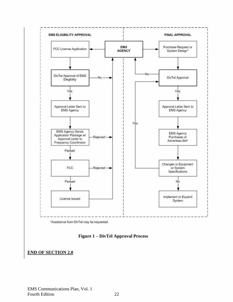
D. Copies of or Applications for FCC Licenses: Copies of FCC licenses or applications, or
an indication of commitment to apply, which indicate whether the project requires radio
frequency coordination, license modifications, or FCC Rule waivers. All applicants in
the EMRS shall obtain an approval letter of eligibility from the DivTel that shall be
included with the application submitted to the FCC-certified frequency coordinator for
EMRS frequencies. Figure-1 depicts how this approval fits in the radio station license
process.
2.11.3 Approval Procedure
A. Final Approval: Implementation of new or expansion of existing telecommunications
systems, regardless of whether purchased with grant funds or not, require a written Final
Approval prior to a commitment to purchase. Furthermore, Final Approval for EMS
Grants Program projects must occur after the date of grant award. A commitment to
purchase is considered to be a purchase order or award of a contract to purchase. It is in
the best interest of each agency to obtain Final Approval prior to commencing formal or
binding competitive processes such as an Invitation to Bid or Request for Proposals.
Allow at least 30 days for DivTel to process the Final Approval request. Figure-1 depicts
how this final approval fits in the implementation or expansion process.
B. Additional Quantities: Procurement of additional quantities of either mobile radio
equipment, handheld portable radio equipment, paging receivers, and associated
accessories which previously received Final Approval, shall not require a subsequent
approval for the additional quantity provided that such procurement is for the same
equipment, is for use by the same organization, and which is purchased within one year
of the date of the original Final Approval. However, each County or Matching Grant
requires a separate and associated Final Approval.
EMS Communications Plan, Vol. 1
Fourth Edition 22
Figure 1 – DivTel Approval Process
END OF SECTION 2.0

EMS Communications Plan, Vol. 1
Fourth Edition 23
3.0 DESIGN CRITERIA FOR EMS COMMUNICATIONS
3.1 General
An EMS communications system must provide the means by which emergency medical
resources can be accessed, mobilized, managed, and coordinated in both normal and adverse
situations. An EMS communications system must therefore employ sufficient communications
paths and operational capabilities among all participants to facilitate the functional EMS
communications designs described in the remainder of this section.
3.2 Citizen Access
The EMS communications system must have the ability to receive and process any incoming
requests that report emergencies and/or require emergency medical assistance. Individual
citizens should have the ability to summon help rapidly in an emergency situation whether for
medical, police, fire, rescue, or other emergency needs. Local, statewide, and national
uniformity is required to fully enable this concept.
The State of Florida 9-1-1 Emergency Telephone Number Plan has provided for a cohesive
statewide emergency telephone number "9-1-1" system to provide citizens with this rapid direct
access to public safety agencies, with an objective of reducing the response time to situations
requiring law enforcement, fire, medical, rescue, and other emergency services.. The 9-1-1 Plan
was developed in response to the Florida Emergency Telephone Act of 1974.
3.3 Vehicle Dispatch and Response (VDR)
On notification of need for emergency medical assistance, the communications system shall
provide a VDR talkgroup/channel enabling prompt dispatch of all required EMS vehicles to the
location of the emergency. The communications system must further enable dispatchers to
communicate with responding vehicles while en route to the scene, while at the scene, while en
route to hospital emergency department facilities, and during their return to availability for
further assignment.
3.3.1 Automatic Vehicle Location (AVL)
Use of AVL systems can provide real-time geographic location of vehicles to ensure the nearest
available vehicle is dispatched to the scene of an incident. Additionally, an AVL system can
display vehicle positions to dispatchers on either tabular and/or graphic displays as well as
providing the information necessary to a Computer-Aided Dispatch (CAD) program when
utilized in a “System Status Management" structure. Consequently, these capabilities are
considered an integral component of VDR.

EMS Communications Plan, Vol. 1
Fourth Edition 24
3.3.2 Crew Alert Paging
In addition to Vehicle Dispatch and Response (VDR), some EMS communications systems may
require the direct alerting of EMS personnel either individually or in groups. This can be
accomplished through the use of either a monitor or paging receivers, or by means of portable
radios with selective call capability. This concept is limited only to such alert paging required to
facilitate the immediate response and action of personnel resulting from a request for emergency
medical services.
3.4 Local Medical Coordination (LMC)
The EMS communications system shall provide EMS field personnel with a communications
system and/or talkgroup/channel that permit the exchange of vital information between EMS
licensed providers, emergency departments and/or medical directors. Minimally, the LMC
channel shall have the capability to provide communications capability to emergency department
personnel from at least a 5-mile radius of the emergency department facility from an EMS
transport unit en route.
3.4.1 Geographical Assigned Hospital LMC
To meet the demands associated with isolated critical situations, Mass Casualty Incidents, MCIs,
and to provide a at least a virtual “stand alone” radio system, hospitals will be assigned a specific
talkgroup/channel. Minimally, this geographically-assigned hospital LMC talkgroup/channel
shall have the capability to provide communications capability to emergency department
personnel from at least a 5-mile radius of the emergency department facility from an EMS
transport unit en route. A UHF MED channel geographically-assigned to each hospital for LMC
is shown in Table 5-1.
3.5 Countywide Medical Coordination (CMC)
In addition to VDR and LMC talkgroup/channel capability, the EMS communications system
within a county should provide a CMC communications talkgroup/channel to enable dispatch
and response between EMS field personnel, hospital emergency departments and dispatch center
personnel during isolated critical situations MCIs during which prolonged use of the VDR
channel would not be feasible due to normal and/or other VDR communications traffic. Such
uses of the CMC talkgroup/channel must be limited only to the temporary duration of such
situations. Ideally this channel should provide communications while the units are at the scene
of the medical emergency. In addition to LMC capability, the EMS communications system can
utilize the CMC talkgroup/channel to enable medical coordination between EMS field personnel
and emergency department personnel during situations in which a vehicle is unable to access an
emergency department LMC talkgroup/channel in isolated critical situations during which
prolonged use of the LMC talkgroup/channel would not be feasible due to other LMC
communications traffic. Such uses of the CMC talkgroup/channel must be limited only to the

EMS Communications Plan, Vol. 1
Fourth Edition 25
temporary duration of such situations. A UHF MED channel geographically-assigned to each
County for CMC is shown in Table 5-1.
3.6 Proprietary Trunked Radio Systems
EMS communications systems may migrate to specialized “trunked” radio systems that will shift
VDR, LMC, and CMC communications to a proprietary radio infrastructure. Radio systems
approved for this technology will meet those agencies requirements for LMC communications
that provide EMS field personnel with a communications system that permits the exchange of
vital information between EMS licensed providers, emergency departments and/or medical
directors.
3.7 Statewide Medical Coordination (SMC)
In addition to VDR capability, the EMS communications system shall provide a mutual aid
communications channel to enable dispatch and response between EMS units and dispatch
centers during situations in which a vehicle is out of its prime area and unable to access a
dispatch center using the VDR talkgroup/channel of that area, and in isolated critical situations
(like MCIs) during which prolonged use of the VDR talkgroup/channel would not be feasible
due to other normal VDR communications traffic. Such uses of the SMC channel must be
limited only to the temporary duration of such situations.
In addition to LMC and/or CMC capability, the EMS communications system must provide a
communications channel to enable medical coordination between EMS field personnel and
emergency department personnel during situations in which a vehicle is out of its prime area and
unable to access an emergency department using the LMC or CMC talkgroup/channels of that
area, and in isolated critical situations (like MCIs) during which prolonged use of the LMC or
CMC talkgroup/channel would not be feasible due to other normal LMC and/or CMC
communications traffic. Such uses of the SMC channel must be limited only to the temporary
duration of such situations.
MED-8 is specifically assigned for SMC communications using radio equipment in the UHF
band. Radio equipment in the 700 MHz and 800 MHz band have interoperability and mutual aid
channels available for SMC communications when assigned for such use on a real-time basis by
the communications center controlling those channels.
3.8 Local Scene Coordination (LSC)
The EMS communications system should have the capability for mobile and portable radios of
the same local area to communicate directly unit-to-unit while on the scene of an emergency
requiring multiple vehicle response. The LSC talkgroup/channel shall be a mobile-only talkgroup
or the “talk-around” channel assigned with the CMC talkgroup/channel for that county. MED

EMS Communications Plan, Vol. 1
Fourth Edition 26
channels geographically assigned may provide this capability. The 700 MHz and 800 MHz band
have interoperability and mutual aid channels available for this capability when assigned for
such use on a real-time basis by the communications center controlling those channels.
3.9 Statewide-Scene Coordination (SSC)
The EMS communications system should have the capability for mobile and portable radios
from different local areas to communicate directly unit-to-unit while on the scene of an
emergency requiring multiple vehicle response. The SSC channel within the state of Florida is
the “talk-around” channel associated with MED-8, 463.1750 MHz transmit, 468.1750 MHz
receive, CTCSS 167.9 Hz. “Talk-around” on other mutual aid channels are governed by the
respective communications plan for direct, unit-to-unit radio communications (i.e., 700 MHz
interoperability and 800 MHz mutual aid channels). The 700 MHz and 800 MHz band have
interoperability and mutual aid channels available for this capability when assigned for such use
on a real-time basis by the communications center controlling those channels.
3.10 Medical Resource Coordination (MRC)
The EMS communications system must provide a direct wireless coordination of EMS resources
between hospitals, providers, and dispatch centers for response to a disaster or mass casualty
incident. Telephone lines between dispatch centers can be used for resource coordination during
normal operations; however, radio communications are needed during situations following
hurricanes, tornadoes, floods, fires, etc., when telephone lines, including cellular systems, are
inoperative, or when telephone central office switching facilities are jammed or disabled.
Typical MRC communications shall be provided by the SMC, MED-8 system unless otherwise
approved by DivTel.
3.11 Biomedical Telemetry
Biomedical telemetry is the process through which data relating to one or more biological
functions of a patient are transmitted by radio or other means, and which are then remotely
received, displayed and/or printed for use by emergency department personnel. Requirements
for biomedical telemetry are subject to the determination of the provider's medical director in
accordance with the Administrative Rules of the Florida Department of Health.
3.12 Interagency/Mutual Aid Coordination
Medical emergencies often involve the response of other public safety services, most commonly
police and fire. Interagency communications are needed to support daily EMS operations and
mutual aid agreements, for the cooperative action of all emergency response units during disaster
situations and at those times when the county Emergency Operations Center (EOC) is involved.

EMS Communications Plan, Vol. 1
Fourth Edition 27
Although the various public safety agencies may operate on different radio frequencies,
interagency radio communications can be provided by use of such mechanisms such as radio
and/or voice over internet protocols (RoIP or VoIP) like the Florida Interoperability Network,
radio frequency control stations, cross-band operations, and inter-service use of common radio
frequencies. Telephone lines between dispatch centers can be used for interagency coordination
during normal operations; however, radio communications are needed during disaster situations
following hurricanes, tornadoes, floods, fires, etc., when telephone lines may be inoperative, or
when telephone central office switching facilities are jammed or disabled. Table 4-1 provides a
list of wide-area and statewide interservice and/or mutual aid frequencies currently in use.
The Florida Interoperability Network (FIN) offers an alternative for interagency/mutual aid
coordination. FIN can patch disparate radio systems and allow for cross-band, interagency
communications. FIN can be referred to as an Extended Area Network (EAN). EAN is
addressed with other terms in section 7.2, SAFECOM Statement of Requirements.
3.13 Back-up Communications
The concept of back-up communications is in general, the provision of sufficient equipment and
procedures to enable an overall improvement in system reliability over time, through either
redundancy or the provision of alternate means. With regard to EMS communications
specifically, the concept of back-up communications is applied to base station or other fixed
radio equipment and is to:
A. Enable VDR communications to continue despite outage of the primary VDR radio base
station.
B. Enable CMC communications to continue despite outage of a primary CMC radio base
station.
C. Enable LMC communications to continue despite outage of the primary LMC radio base
station.
In this plan, the back-up communications concept includes only fixed station radio equipment,
and does not include any communications other than VDR, LMC, and CMC.

EMS Communications Plan, Vol. 1
Fourth Edition 28
3.14 Telephone Interconnection
The EMS communications system may provide interconnection with specialty information and
treatment centers for hazardous material spills, burn, hyperbaric oxygen, spinal cord injury, and
neonatal centers. In addition, the required level of confidentiality may exceed what is typically
available within land-mobile radio systems. This concept includes the ability for EMS personnel
to exchange information directly with sources located outside their EMS communications system
and at diverse locations only accessible via the public switched telephone network.
END OF SECTION 3.0

EMS Communications Plan, Vol. 1
Fourth Edition 29
4.0 FREQUENCY PLAN
4.1 Background
The FCC created the EMRS out of the SERS. Effective April 2, 1993, FCC Rules designated
International Municipal Signal Association/International Association of Fire Chiefs
(IMSA/IAFC) as the certified frequency coordinator for EMRS. The FCC concluded with their
discussion in the Report & Order of PR Docket No. 91-72 that the IMSA/IAFC is expected "...to
verify that all applicants are compatible with existing regional and local emergency medical
plans."
This change in FCC Rules was not intended to displace local and state planning efforts, but
rather to ensure a single point of contact to the Commission for matters relating to applications
for coordination and licensing as well as to provide a nationally uniform and efficient procedure
for such applications.
It is apparent that any successful local or state radio frequency planning effort must be consistent
with the FCC-certified coordinating organization procedures. DivTel will maintain liaison with
the certified coordinators toward the mutual goal of effective and efficient use of the radio
spectrum by EMS agencies within Florida.
4.2 Channel Allotment Principles
Within the domain of the PLMR services, CFR 47, and the limits of frequency modulation (FM)
radio technology, there are two basic approaches to the assignment of radio channels consistent
with the principles of spectrum efficiency and effectiveness. They are the Geographic Allotment
method and the Real-Time Allotment method. Of these, the Geographic method is simpler and
less costly to implement, particularly for small systems in less frequency-congested areas. The
Real-Time method results in considerable improvement in spectrum efficiency and freedom from
harmful interference in more congested areas.
Spectrum efficiency is the extent to which radio traffic occupies radio channels over a large
geographic area. Greater spectrum efficiency demands that channel bandwidth be minimized,
channels be re-assigned as closely as possible, and that traffic loading on each channel be
maximized. Application of this principle is of critical importance in most areas of the state.
Spectrum effectiveness, on the other hand, is the extent to which the necessary channel is
available when and where needed, and is free from harmful interference. The fundamental goal
in any radio channel allotment scheme is, therefore, to achieve the necessary effectiveness, while
maintaining the greatest efficiency.

EMS Communications Plan, Vol. 1
Fourth Edition 30
4.2.1 Harmful Interference
Two types of harmful interference are defined below – co-channel and adjacent channel:
A. Co-channel Interference: For frequencies below 470 MHz, harmful interference is
defined by this Plan as an “undesired” signal received instead of the “desired” signal.
Technically, the undesired signal must have greater than a 5 percent probability of
exceeding a power level of 12 dB, 6dB in base-to-base situations, less than a desired
signal power level, when the desired signal has a 95% probability of achieving a power
level required to produce either 20 dB quieting or 17 dB SINAD per the
Telecommunications Industry Association/Electronics Industries Association (TIA/EIA).
For channels in the 470 MHz, 700 MHz, and 806 MHz bands, channel allocation
principles and interference criteria are governed by FCC Rules. For 700 MHz General
Use channels, 821 MHz channels, and 700 MHz Interoperable Use channels, allocation
principles and interference criteria are governed by the Florida - Region 9 Plan for 700
MHz Public Safety Radio Communications, the Florida - Region 9 Plan for 800 MHz
Public Safety Radio Communications, and Florida’s 700 MHz Public Safety
Interoperability Channel Plan, respectively.
B. Adjacent-Channel Interference: Adjacent-channel interference is defined as "harmful"
when a desired 95 percent reliability signal is degraded by an undesired 5 percent
reliability adjacent channel signal by more than the criteria established by TIA/EIA
standards. Channel assignments are based on an analytical showing of no harmful
interference. Adjacent channel interference is not normally considered in other frequency
bands except for the criteria established in the Florida - Region 9 Plan for 700 MHz
Public Safety Radio Communications, and the Florida - Region 9 Plan for 800 MHz
Public Safety Radio Communications, and Florida’s 700 MHz Public Safety
Interoperability Channel Plan.
4.2.2 Geographic Allotment
Geographic Allotment is the assignment of a channel such that a licensee has generally full-time
and exclusive use of that channel within an agreed geographic area. Once assigned, the channel
is dedicated to that user and is not available for others even when the channel is not in use. In
practice, channel sharing agreements, or primary/alternate schemes, will further improve channel
efficiency in such a system, but only to a limited extent. As channel loading for any user
increases, the benefits of channel sharing and alternate channel agreements decrease.
The Geographic Allotment method is both successful and practical in those areas where the radio
traffic is either sufficiently low, and/or that the available spectrum satisfies all user needs within
a "channel re-use distance" of roughly 70 miles. Within the state of Florida, application of the
Geographic Allotment concept presents special difficulties since the majority of the state, from
the panhandle through the peninsula, is scarcely more, and often less, than 100 miles in width.
The Geographic Allotment method is normally applied on all VHF channels, both Low and High
Bands, and 700/800 MHz conventional, non-trunked, channels. The 450-470 MHz (UHF) Band

EMS Communications Plan, Vol. 1
Fourth Edition 31
utilizes both Geographic and Real-Time Allotment in the case of EMS Communications.
4.2.3 Real-Time Allotment
Real-Time Allotment is the process through which each available radio channel is assigned to a
particular communications path by the dispatch center, mobile/base link, on an as-needed
incident-by-incident basis, and such that the same channel may be assigned to many different
users, at different times, all within the same geographic area. The Real-Time Allotment method
requires that each mobile radio and the base station system be capable of transmitting and
receiving on all of the radio channels to be allocated.
In practice, mobile radios are normally equipped with all necessary channels, while fixed control
points operate via direct control, wireline or other link through a central base station facility,
which is also equipped to transmit and receive on all necessary channels. A fundamental
requirement for fully successful operation of a Real-Time Allotment system is that the reliable
radio coverage area of each base station channel be very nearly the same.
The "trunking" concept is similar to Real-Time Allotment in that channel assignments vary with
respect to time rather than with respect to geography. However, computer-controlled trunking
systems still require approximately 70-mile minimum separation between independent systems
using the same frequencies.
The Real-Time Allotment method, within Florida Emergency Medical Services communications,
may be applied to MED channels 1 through 7 and MED channels 12 through 72 of the UHF
Band portion of the Emergency Medical Radio service.8
4.3 Vehicle Dispatch and Response Channels
4.3.1 Ground Vehicle Communications
Radio frequency or frequencies for which the applicant is eligible under FCC Rules, and meets
the requirements of this Plan and FCC limitations, may be used for Dispatch and Response
communications with EMS ground vehicles. This includes VHF Low Band (30-50 MHz), VHF
High Band (150-160 MHz), 220 MHz Band, UHF Band (450-473 MHz, including UHF TV
channel sharing frequencies in Florida), 700 MHz Band, and the 800 MHz Band, in both
conventional and trunked modes.
The use of MED channels 9, 92, 10 or 102 for VDR shall be in accordance with the statewide
allotment plan for these frequencies. Currently approved frequency and CTCSS tone allotments
of MED-9 92, 10 or 102 are shown on Table 4-2, Florida MED Channel Allotments.
The use of any of MED channels 1 through MED channels 7 and 12 through 72 for VDR shall
also be in accordance with the statewide allotment plan, and such allotments are subject to no
8 MED channel sequences 1, 2, 3, … 7 and 12, 22, 32, … 72 are referenced for specific planning, implementation and operational use.

EMS Communications Plan, Vol. 1
Fourth Edition 32
harmful interference to LMC and/or CMC operations on these channels. MED-8 shall not be
used for primary VDR communications except to satisfy the SMC and/or back-up requirements
defined in Section 5.0.
4.3.2 Air Ambulance Communications
Communications for aeromedical services may utilize certain radio frequencies within the
Aviation Services of FCC Rules Part 87, "Aeronautical Enroute and Aeronautical Fixed
Stations." The scope for Aeronautical Enroute stations is limited to the necessities of safety and
primary operation of the aircraft. Sub-part I does not allow for medical communications. These
channels are associated with Air-traffic Control Centers, Airport Control Towers and “Unicom”
communications systems. By design these radio systems are limited in the communications
coverage capabilities they would provide for low flying rotorwing aircraft. Given the limitations
associated with these radio frequencies by rule and/or design, their use by prehospital for flight
following is not recommended for flight following.
Frequencies within the applicable PLMR services of FCC Rules Part 90 may be utilized for Air
Ambulance Dispatch and Response and/or Medical Coordination on a secondary basis to land-
based systems. Licensing for implementation or expansion of air ambulance communications on
any frequencies within the Public Safety Pool requires prior approval by DivTel.
DivTel has established specific radio frequency allotments both “Air Primary” and “Air
Secondary” within Florida for aeromedical Dispatch and Response communications. Rotor-
winged aircraft that are licensed for prehospital will be assigned specific UHF pair within the
453/458 MHz band as Air Primary for VDR. Rotor-winged aircraft, which provide inter-facility
transports only, will be licensed in the VHF-Lo Band, 47 MHz. DivTel will assists these
agencies with waivers to the FCC rules to increase the output power of the radio from the aircraft
to facilitate the longer transports associated with these aircraft.
All licensed rotor-winged aircraft and dispatch centers within the state of Florida shall have the
ability to communicate on the Air Secondary frequency 155.340 MHz, CTCSS 167.9 Hz. This
provides continued flight-following with the aircraft while medical crews utilize their EMS radio
to provide medical reports (LMC, CMC or SMC). Secondarily, this Air Secondary frequency
provides a “Statewide” radio system for MCI coordination with aircraft that would necessitate
communications with the various aircraft, dispatch centers and/or landing zone management.
Further, this frequency shall provide EMS helicopter personnel with continued safety of flight
situations in which a vehicle is out of its prime area an unable to access its dispatch center. Such
use of the Air Secondary channel shall be limited only to the temporary duration of such
situations unless otherwise approved in writing by DivTel. This Air Secondary frequency is also
in concert with the Mutual Aid channels “Red, White and Blue” channels.
EMS Communications Plan, Vol. 1
Fourth Edition 33
4.4 Countywide Medical Coordination Channels
MED channels 1 through 7 and MED channels 12 through 72 may normally be used for primary
CMC for both ground and air ambulance vehicles. Use of these channels shall be in accordance
with the statewide allotment plan. Currently-approved frequency and CTCSS tone allotments for
MED-1 through 7 and MED-12 through 72 are shown on Table 4-2, Florida MED Channel
Allotments.
If the primary CMC channel to be implemented or expanded would cause harmful interference to
or from the primary LMC channel of another user, then DivTel will analyze the MED channel
allotments of all affected systems and establish an appropriate plan that may require the
reconfiguration of existing systems.
The use of any radio frequencies other than MED-1 through MED-7 and MED-12 through 72 for
primary CMC shall be only as specifically approved by DivTel.
MED-8, MED-82, MED-9, MED-92, MED-10, and MED-102 shall not be used for primary
LMC except for MED-8, which may be used to satisfy the SMC and/or back-up requirements
defined in Section 5.0 of this Plan.
4.5 Local Medical Coordination (LMC) Channels
The primary requirements of the EMS Communications Plan are for every EMS permitted
vehicle to have the capability for two-way radio communications with a higher level of medical
care “Medical Control.” Specifically, this capability shall exist for radio communications should
the EMT/firefighter/paramedic need to deviate from established medical protocols and/or request
additional medical assistance from the medical director and/or hospital. Accordingly, every
hospital emergency department shall have the capability to reliably communicate to at least a 5-
mile radius of its facility on the LMC channel approved or assigned by DivTel in accordance
with Section 5.0 of this Plan.
4.6 Medical Resource Coordination (MRC) Channels
Historically, two primary channels for Medical Resource Coordination within Florida have been
on MED-8, transmit and receive on 463.175 MHz with CTCSS of 167.9 Hz, and on 155.340
MHz (transmit and receive, with no CTCSS). Each of these channels is used for MRC
communications in parts of the state, and each has advantages and disadvantages depending on
both geographic location and technical considerations.
In northern Florida, MED-8 is generally used due to other uses of 155.340 MHz within Georgia
and Alabama. MED-8 is used in many other parts of Florida where 155.340 MHz is in use for
land-mobile communications.

EMS Communications Plan, Vol. 1
Fourth Edition 34
155.340 MHz is used in some areas where MED-8 point-to-point use has been determined
unfeasible. In some of the more congested areas of the state, neither channel is in use for either
technical problems with interference, or simply the lack of a wireless MRC system. Microwave,
700 MHz, and 800 MHz communications are other systems that may potentially qualify as the
MRC channel for a geographic region.
The establishment of a cohesive network of MRC systems within Florida is a goal of DivTel.
Until such a plan is established, the implementation or expansion of MRC systems will be
determined on a case-by-case basis.
4.7 Statewide Medical Coordination (SMC) Channel
MED-8, 463.175 MHz base transmit, 468.175 MHz base receive, with CTCSS of 167.9 Hz, shall
be used for primary SMC in permitted vehicles with UHF radio equipment during times the
vehicles are used outside their normal operating area, and LMC, CMC, or VDR
talkgroups/channels are not available. MED-8 was segregated by the Plan and established as the
only UHF MED channel for SMC. The capabilities of the SMC channel are designed to provide
two objectives within the EMS community.
1. Primarily, every licensed EMS transport with UHF radio equipment, regardless of other
frequencies radio systems employed within a region, could communicate with a hospital
in any region if necessary.
2. Additionally, EMS systems in the state have established MED-8 SMC capabilities within
their communications/dispatch centers to provide assistance for out-of-region EMS units
with UHF radio equipment while in transit through the region and backup to the EMS
VDR channel.
Simply put, MED-8 has been established to maintain UHF radio communications with
emergency departments, EMS dispatch centers, and/or other EMS communications systems
throughout the state while transporting patients. The intent of the Plan is to establish a common
medical communications system, channel, which would provide the EMT/paramedic with UHF
radio equipment the ability to communicate within a county and/or municipality regardless of
that region’s primary communications infrastructure.
Mutual aid channels identified for public safety (particularly 700 MHz and 800 MHz) use may
be used in accordance with that respective communications plan, and during times the vehicles
are used outside their normal operating area, and LMC, CMC, or VDR talkgroups/channels are
not available.
4.7.1 SMC (MED-8) System Standard
A. Design Specifications: This Plan provides for a statewide system for selective activation
of regional MED-8/SMC repeater stations and selective addressing of local emergency
departments and county EMS dispatch centers to satisfy the SMC requirements of the this

EMS Communications Plan, Vol. 1
Fourth Edition 35
Plan. The end user accomplishes all necessary selective signaling. Other than the
initiating party and the receiving party, no additional human intervention will be
necessary to establish or maintain two-way radio communication via this addressing
system.
These signaling aspects of this plan anticipate the use of Dual-Tone Multi-Frequency
(DTMF) for selective access to repeaters and selective addressing of individual stations.
The DTMF is an industry standard tone scheme used for audio signaling and control
purposes and is generally defined as the simultaneous generation of two specific audio
tones, such as when any one button of a standard DTMF keypad is depressed. DTMF is
compatible with the original AT&T “Touch-Tone®” system initially used in telephone
systems.
The overall architecture of the proposed MED-8 statewide radio system will provide for
extended-range, vehicle-to-base communication by virtue of at least one wide-area SMC
repeater in each county. Note that all SMC repeaters employ the identical MED-8
frequency pair and CTCSS tone in accordance with this Plan regardless of their
geographic separation. Consequently, it is essential that all MED-8 repeaters must
remain in the repeat disable mode unless actually being used to relay a communication
between two radio stations. Otherwise, it is likely that nearby repeaters will interfere
with one another and disrupt or altogether prevent any associated radio communications.
Another feature of the radio system is the continued ability to operate, within normal
range limits, even if repeaters are not available due to equipment failure, severe weather,
or other reasons. This capability applies to both mobile and radio frequency control
stations, and is typically known as repeater talk-around (SSC). When operating in talk-
around mode, the DTMF signaling aspects of the system are fully preserved; but, subject
to the native range of the radios involved in any particular exchange. If extended talk-
around range is required for any particular hospital or dispatch facility, consideration
should be given for use of an omni-directional antenna for the MED-8 control station,
rather than the directional antenna typically provided.
B. Procedures: In a typical MED-8 communication in fictitious Paradise County, county
code 68, a mobile radio user would activate the appropriate regional MED-8 repeater by
sending DTMF codes “6”, “8” and “1”, designating the first and only repeater in county
68, immediately followed by a “*”, wake-up, code if required. Once the repeater is
activated, the mobile user would address the desired control station and these signals
would be re-transmitted and heard by all monitoring MED-8 stations. If necessary, a
DTMF regenerator could be installed in the repeater station to improve the purity of the
re-transmitted tones.
In this example, the mobile unit would transmit selective address “6827” to activate the
control station decoder at the emergency department of County General Hospital. Upon
hearing the correct DTMF sequence, the control station at the hospital would decode the
selective address, wake up, and the staff could hear the subsequent voice call. If desired,
the hospital decoder could also activate some type of attention-getting device to ensure

EMS Communications Plan, Vol. 1
Fourth Edition 36
that the emergency department staff is made aware of an incoming call. Once the staff
answers the radio call, the radio exchange will continue until completed, at which time
the staff could manually reset the decoder, or the decoder could be set to reset
automatically after a pre-determined time-out period.
At the same time, the mobile unit crew would deactivate the regional repeater by sending
DTMF codes “6”, “8”, and “1”, followed by a “#”, knock-down, code if required. The
repeater would then revert to the repeat-disable mode and monitor the receive frequency
for any subsequent calls.
NOTE: Should a regional repeater be out-of-service for whatever reason, the same basic
calling procedures would apply after first switching to the repeater-talk-around, simplex,
mode of operation.
Each regional MED-8 repeater station will be equipped with a DTMF decoder, set to
respond to at least two groups of DTMF tones, and an internal DTMF re-generator.
C. Regional DTMF Addresses:
Each county is assigned a unique two-digit county code (example: 68). Each regional
repeater will be assigned a related three-digit address (example: 681). Each control
station will be assigned a unique four-digit selective address, subordinate to the county
code (example: 6815).
This scheme will allow for up to 99 counties with up to nine regional repeaters and nearly
100 uniquely addressed control stations per county. In addition, all DTMF decoders will
respond to a two-digit code (00) as a statewide ALL-CALL address, a four-digit common
address as a countywide call (example for fictitious Paradise County would be: 6899),
and a unique four-digit individual address (example: 6842).
The following list of primary county DTMF addresses was derived from an alphabetical
list of Florida counties complied by the State EMS Office for reporting purposes:

EMS Communications Plan, Vol. 1
Fourth Edition 37
01 Alachua 19 Franklin 37 Leon 55 St. Johns
02 Baker 20 Gadsden 38 Levy 56 St. Lucie
03 Bay 21 Gilchrest 39 Liberty 57 Santa Rosa
04 Bradford 22 Glades 40 Madison 58 Sarasota
05 Brevard 23 Gulf 41 Manatee 59 Seminole
06 Broward 24 Hamilton 42 Marion 60 Sumter
07 Calhoun 25 Hardee 43 Martin 61 Suwannee
08 Charlotte 26 Hendry 44 Monroe 62 Taylor
09 Citrus 27 Hernando 45 Nassau 63 Union
10 Clay 28 Highlands 46 Okaloosa 64 Volusia
11 Collier 29 Hillsborough 47 Okeechobee 65 Wakulla
12 Columbia 30 Holmes 48 Orange 66 Walton
13 Dade 31 Indian River 49 Osceola 67 Washington
14 Desoto 32 Jackson 50 Palm Beach 70 Kennedy Space Center
15 Dixie 33 Jefferson 51 Pasco 71 Pensacola Naval Air Station
16 Duval 34 Lafayette 52 Pinellas 72 Tyndall Air Force Base
17 Escambia 35 Lake 53 Polk 73 Macdill Air Force Base
18 Flagler 36 Lee 54 Putnam 74 Patrick Air Force Base
75 Jacksonville Naval Air Station
99 Countywide All Call Suffix
00 Statewide All Call Suffix
D. In-County DTMF Addresses: Each individual county will be responsible for assigning
DTMF codes to repeaters and control stations within their respective area in strict
accordance with the addressing scheme noted in this Plan. The following is an example
addressing the scheme for “Paradise County” (county code 68):
NORTH (primary) MED-8 repeater access – 681
SOUTH (secondary) MED-8 repeater access – 682
Countywide ALL-CALL code – 6899
County EMS dispatch center – 6801
Hospital A – 6823
Hospital B – 6834
Hospital C – 6838
Hospital D – 6842
Hospital J – 6859
City A EMS dispatch center – 6863
City B EMS dispatch center – 6867
County Emergency Management/EOC – 6874
Private ambulance dispatch center – 886
NOTE: In this example that the first two digits are always 68 or the county code, while
the second two digits can be randomly assigned, but must result in a number that is not
assigned to any other station within the County.
E. Equipment Considerations:
1. Mobile Units: All MED-8equipped mobile radios are essentially capable of
operation on the new system. Additional programming may be required to add
talk-around capability. DTMF replacement microphones are readily available
from numerous sources and can be attached to most mobile radios with little
difficulty.

EMS Communications Plan, Vol. 1
Fourth Edition 38
2. Repeaters: DTMF decoding and re-generating devices are generally available for
LMR fixed equipment. DivTel has identified an appropriate, readily available
product that can be attached to most typical MED-8 repeater stations by local
technicians.
3. Hospitals or Dispatch Centers: If a hospital or dispatch center currently has a
separate MED-8 station, it may be possible to convert the existing equipment to
the new configuration. However, those medical facilities that currently operate
primary or backup repeater stations that function on one or more of the standard
MED channels may prefer to leave that equipment undisturbed. Rather than
attempting to integrate the new MED-8 functionality into existing radio
equipment, it may ultimately be more cost effective for hospitals and dispatch
centers to purchase a small UHF RF control station specifically configured for
remote control, talk-around, and built-in DTMF signaling.
4. DTMF Devices: As noted above, the necessary DTMF functionality could be
incorporated into the RF control station itself. Alternatively, a separate
customized remote control device with DTMF encode and decode capabilities
could be utilized in concert with a standard RF control station. A compatible
desktop DTMF remote control device that has already been tested on a similar
radio system in Florida is available from Zetron. DTMF decoding devices from
other manufacturers may also be compatible with the proposed MED-8 system
signaling parameters.
F. Mobile Radio Configurations: In order to realize the most utility and flexibility for a
common statewide EMS radio system, all associated mobile radios should be configured
in essentially the same way – a standardized configuration and, as applicable, a standard
naming convention.
4.7.2 Interservice/Mutual Aid Channels
Radio channels for interservice and mutual-aid operations may be utilized only within the
provisions of FCC Rules and Regulations, Part 90, "Operating Requirements". The portions of
those rules applicable to EMS organizations are summarized in Section 4.7.3 below. Contingent
on eligibility or licensee concurrence, specific wide-area and statewide channels may be used for
Interservice/Mutual Aid. Such operations are discussed in Section 4.7.5.
4.7.3 FCC Rules
FCC Rules relating to interservice and mutual aid communications can be classified into the
following General Rules, and rules for Base Station Communications, and Mobile Unit
Communications:
EMS Communications Plan, Vol. 1
Fourth Edition 39
A. General Rules are established for:
1. Interstation Communications in Part 90.417(a) & (b).
2. Civil Defense Communications in Part 90.411.
B. Base Station Communications are established for:
1. Frequencies Below 450 MHz in Part 90.419(a).
2. Frequencies Above 450 MHz in 90.419(b).
C. Mobile Unit Communications are established in Part 90.421 for the operation of mobile
units in vehicles not under the control of the licensee. Arrangements for such use are
normally made by means of written agreement between the licensee and user. Refer to
the sample sharing agreement in Section 4.7.4. The written agreement should include the
following:
1. Typed on the agency's letterhead granting the sharing agreement.
2. State the quantity of mobile, or portable radios covered in the agreement.
3. State the call sign, frequency(ies), and maximum power output associated with
the written agreement, and other technical parameters authorized on the granting
agency's radio station license.
4. State the written agreement applies to operations in cooperation and coordination
with the activities of the licensee per FCC Rule Part 90.421.
5. State the granting agency's reserved right to effectively eliminate the possibility of
unauthorized operation that ultimately could result in terminating the written
agreement.
Overall, FCC Rule 90.421 does not specifically provide for interservice mobile operation by
emergency medical eligibles on frequencies in the Fire, Highway Maintenance, or Forestry-
Conservation Radio Services, or on any non-Public Safety frequencies. Part 90.421(c) however,
provides a general rule regarding mobile unit communications such that "...frequencies assigned
to licensees in the Private Land Mobile Radio service may be installed in the facilities of those
who assist the licensee in emergencies and with whom the licensee must communicate in
situations involving imminent safety to life or property."

EMS Communications Plan, Vol. 1
Fourth Edition 40
4.7.4 Example of a written agreement
________________________________ (grantor) authorizes __________________________ (grantee) to
operate_________________ (quantity) mobile (or portable) radios. Such operation shall be per the
following parameters.
Call Sign Frequency(ies) Max. Power Other Technical Parameters
______________ ______________ __________ _________________________
______________ ______________ __________ _________________________
______________ ______________ __________ _________________________
(Use additional attachments as necessary for more frequencies/channels)
This written agreement applies to operations in cooperation and coordination with activities of the
licensee per FCC §90.421. Furthermore, grantor reserves the right to effectively eliminate the possibility
of unauthorized operation that ultimately could result in terminating this written agreement.
______________________ (authorized signor)
______________________ (typed signor's name)
______________________ (authorizing agency)
______________________ (date)
4.7.5 Florida UHF MED Channel Allocations
Within FCC Rules Part 90, many frequencies may be used for interservice and mutual-aid
operations on a local basis by EMS organizations consistent with the FCC limitations
summarized in Section 4.7.3. On a wide-area or statewide basis however, only a small number
of channels are available for such use, and are listed in Table 4-1.
The use of these or any other frequencies for interservice/mutual-aid use for which the user is not
directly eligible, must be in accordance with the applicable FCC Rules.

EMS Communications Plan, Vol. 1
Fourth Edition 41
Table 4-1 – Wide-Area and Statewide Interagency/Mutual-Aid Frequencies
FREQUENCY Base TX/RX (MHz)
ANS Standard
9
Name
New-Rebanded FREQUENCY
Base TX/RX (MHz) CTCSS
(Hz) RADIO
SVC PRIMARY USE AREA
39.10/39.10 n/a n/a 156.7 PW
Emergency Management
(Civil Defense) Statewide
39.18/39.18 n/a n/a 156.7 PW
Emergency Management
(Civil Defense) Statewide
45.86/45.86 LLAW3D n/a None PW
Law Enforcement
Emergency
Wide-
Area
154.950/154.950 n/a n/a None PW
Law Enforcement
Emergency
Wide-
Area
460.275/465.275 n/a n/a None PW
Law Enforcement
Emergency
Wide-
Area
155.370/155.370 n/a n/a None PW
Law Enforcement
Intercity Statewide
154.265/154.265 VFIRE22 n/a None PW
Fire Mutual-Aid "Red"
(Mobile/Portable Only) Statewide
154.280/154.280 VFIRE21 n/a None PW
Fire Mutual-Aid "White"
(Base and Mobile) Statewide
154.295/154.295 VFIRE23 n/a None PW
Fire Mutual-Aid "Blue"
(Mobile/Portable Only) Statewide
155.340/155.340 VMED28 n/a None PW
Air Secondary-EMS
Air Transport Statewide
463.175/468.175 n/a n/a 167.9 PW
Statewide Medical
Coordination-MED-8 Statewide
463.1875/468.1875 n/a n/a 167.9 PW
ESF 8 Medical
Coordination – MED-82 Statewide
769.24375/799.24375 7CALL50 n/a NAC $293 SG/SY
National Public Safety
Interoperability Calling Channel10
769.74375/799.74375 7TAC55 n/a NAC $293 SG/SY
National Public Safety
Interoperability Tactical Channel
770.24375/800.24375 7TAC56 n/a NAC $293 SG/SY
National Public Safety
Interoperability Tactical Channel
770.99375/800.99375 7GTAC57 n/a NAC $293 SG/SY
National Public Safety
Interoperability Tactical Channel
773.25625/803.25625 7CALL70 n/a NAC $293 SG/SY
National Public Safety
Interoperability Calling Channel
773.75625/803.75625 7TAC75 n/a NAC $293 SG/SY
National Public Safety
Interoperability Tactical Channel
774.25625/804.25625 7TAC76 n/a NAC $293 SG/SY
National Public Safety
Interoperability Tactical Channel
774.85625/804.85625 7GTAC77 n/a NAC $293 SG/SY
National Public Safety
Interoperability Tactical Channel
853.3875/808.3875 n/a 854.6375/809.6375 210.7 GE
Public Safety Mutual-Aid
(FCC Channel
(96 old – 256 new)11
Statewide
866.0125/821.0125 8CALL90 851.0125/806.0125 156.7 GE
National Public Safety
Mutual Aid Calling
(FCC Channel
601 old – 01 new)12
Nationwid
e
9 APCO/NPSTC ANS 1.104.1-2010 naming standard can be found at: http://apcointl.org/new/commcenter911/documents/APCO-NPSTC-
ANS1-104-1web.pdf 10
See section 2.5. 11
See Section 2.8.
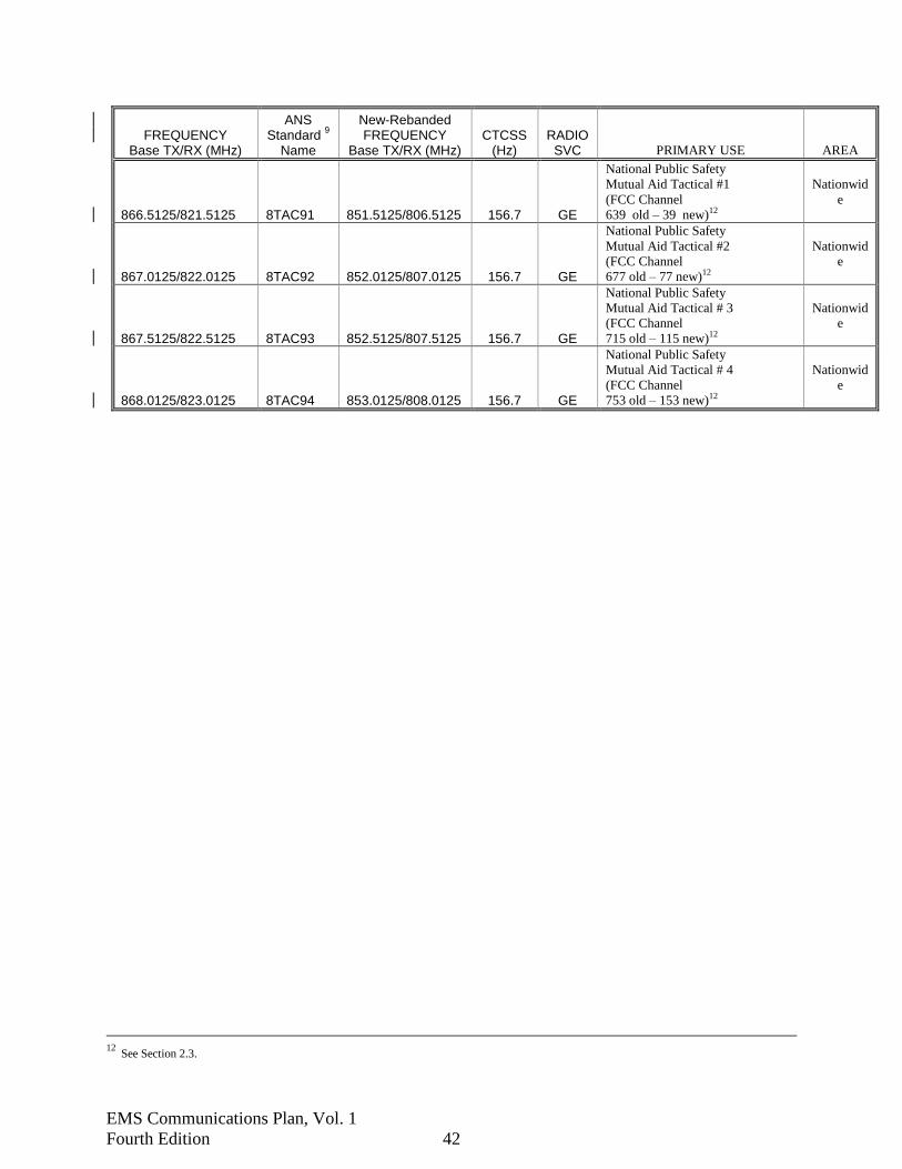
EMS Communications Plan, Vol. 1
Fourth Edition 42
FREQUENCY Base TX/RX (MHz)
ANS Standard
9
Name
New-Rebanded FREQUENCY
Base TX/RX (MHz) CTCSS
(Hz) RADIO
SVC PRIMARY USE AREA
866.5125/821.5125 8TAC91 851.5125/806.5125 156.7 GE
National Public Safety
Mutual Aid Tactical #1
(FCC Channel
639 old – 39 new)12
Nationwid
e
867.0125/822.0125 8TAC92 852.0125/807.0125 156.7 GE
National Public Safety
Mutual Aid Tactical #2
(FCC Channel
677 old – 77 new)12
Nationwid
e
867.5125/822.5125 8TAC93 852.5125/807.5125 156.7 GE
National Public Safety
Mutual Aid Tactical # 3
(FCC Channel
715 old – 115 new)12
Nationwid
e
868.0125/823.0125 8TAC94 853.0125/808.0125 156.7 GE
National Public Safety
Mutual Aid Tactical # 4
(FCC Channel
753 old – 153 new)12
Nationwid
e
12
See Section 2.3.

EMS Communications Plan, Vol. 1
Fourth Edition 43
Table 4-2 – Florida Countywide MED Channel & CTCSS Allotments
MED Channel
1 2 3 4 5 6 7 9 92 10 102
COUNTY-STATE Identifier CTCSS (Hz)
Alachua-ALC 118.8 118.8
Baker-BAC 167.9
Bay-BAO 167.9
Bradford-BRD 94.8
Brevard-BRV 127.3
Broward-BRW 173.8 173.8
Calhoun-CLN 156.7
Charlotte-CHA 167.9 167.9
Citrus-CIR 167.9 167.9
Clay-CLA 167.9
Collier-COL 192.8 192.8
Columbia-CLA 131.8
Dade-MDC 203.5
Desoto-DEU 131.8
Dixie-DIX 118.8
Duval-DVL 146.2 146.2
Escambia-ESC 110.9 36.5 10.9
Flagler-FLR 136.5
Franklin-FRN 156.7/167.9
Gadsden-GAD 203.5 203.5
Gilchrist-GIL 94.8
Glades-GLA
Gulf-GLF 167.9 167.9
Hamilton-HLN 210.7
Hardee-HAR 127.3
Hendry-HEN 107.3
Hernando-HER 146.2 146.2 146.2
Highlands-HIG 123.0 123.0
Hillsborough-HIC 127.3 110.9
Holmes-HMS 167.9
Indian River-IRC 118.8 118.8
Jackson-JAC 146.2
Jefferson-JEF 156.7
Lafayette-LAF 110.9

EMS Communications Plan, Vol. 1
Fourth Edition 44
MED
Channel 1 2 3 4 5 6 7 9 92 10 102
COUNTY-STATE
Identifier CTCSS (Hz)
Lake-LKC 32-192.8 192.8
Lee-LEE 110.9 110.9
Leon-LEO 156.7 156.7
Levy-LVY 127.3
Liberty-LBE 156.7
Madison-MAD 146.2
Manatee-MNT 167.9
Marion-MAO 127.3 127.3 127.3
Martin-MTC 146.2 146.2
Monroe-MON 156.7
Nassau-NAS 136.5
Okaloosa-OKA 156.7
Okeechobee-OKC 167.9
Orange-ORA 156.7 156.7
Osceola-OSC 114.8 114.8
Palm Beach-PBC 127.3 127.3 127.3 127.3 127.3
Pasco-PSC 110.9
Pinellas-PIN 203.5
Polk-POL 103.5 203.5 203.5
Putnam-PUT 103.5 103.5
St. Johns-SAJ 167.9
St. Lucie-SLU 136.5
Santa Rosa-SRC 136.5
Seminole-SEM 110.9
Sumter-SUM 72-192.8 192.8
Suwannee-SUW 110.9
Taylor-TAY 118.8
Union-UNC 156.7
Volusia-VOL 136.5 136.5
Wakulla-WAK 156.7
Walton-WTN 167.9
Washington-WSN 146.2
END OF SECTION 4.0

EMS Communications Plan, Vol. 1
Fourth Edition 45
5.0 SYSTEM REQUIREMENTS
5.1 General
The primary requirements of the EMS Communications Plan are for every permitted vehicle
within their respective region (i.e., countywide) to have the capability for two-way radio
communications with 1) its dispatch center, 2) with a higher level of medical care “Medical
Control” and 3) with eachother. These three capabilities make up what can be referred as the
EMS triangle of communications (EMS dispatch centers, EMS facilities, and EMS providers).
Without comprehensively completing the EMS triangle of communications throughout the
region, EMS communications within the region is compromised. Deviation from completing a
single EMS triangle of communications by just one agency in the region may require a second
set of system requirements, effectively creating a second and unwanted equipment purchase by
all EMS agencies in the region. Regionalizing EMS communications on a “per-County” basis
avoids unnecessary radio equipment, particularly for every permitted vehicle, while minimizing
costs for EMS dispatch centers and EMS medical care facilities – and the counties in general.
The radio communications capability for “Medical Control” shall exist to facilitate the
EMT/firefighter/paramedic needing to deviate from established medical protocols and/or request
additional medical assistance from the medical director and/or hospital, in addition to announce
patient information and estimated time of arrival.
The system requirements defined in the following sections are the requirements by which
DivTel, EMS communications approval or disapproval will be determined for implementation of
new EMS communications systems or for expansion of existing systems.
These requirements relate only to "system level" attributes of communications systems;
requirements for individual equipment items are defined in Section 6.0, EQUIPMENT
REQUIREMENTS.
These system requirements make reference to specific EMS communications system concepts
that are defined in Section 3.0.
For aspects of system configurations not explicitly included in the following sections, their
approval will be determined on a case-by-case basis by DivTel. Migrating from a statewide
concept to a regional concept may require case-by-case considerations for each EMS agency
within that respective region to avoid temporary compromise to existing radio communications
capability making up the EMS triangle of communications.
As these system requirements are subject to change at the determination of DivTel, EMS
Communications, please verify the most current requirements as may apply to a particular
system application prior to a request for approval.

EMS Communications Plan, Vol. 1
Fourth Edition 46
5.2 Communications Coverage Contour
5.2.1 Communications Reliability
The area of reliable communications is defined as having been engineered for a 95 percent
probability of communications at the defined coverage contour, or 98.3 percent probability of
communications over the defined coverage area, based on a received signal level of either 20 dB
quieting or 17 dB SINAD, EIA, for the worst case of either talk-out, base to mobile, or talk-back,
mobile to base. The defined contour of reliable radio coverage shall normally be the boundary of
the operating area for which the provider routinely operates unless DivTel has approved a
different boundary for a particular system. This provides for reliable communications at 95
percent of the locations along the contour, 95 percent of the time. The probability improves as
the associated radio transmitter/receiver site is approached, thus achieving a 98.3 percent
probability across the area within the contour.
The coverage contour shall be the normal calculated coverage recommended and/or designed by
DivTel for stations established for primary use of VDR and/or LMC. Stations serving only as a
back-up to the primary station, SMC and/or CMC may have a lesser coverage contour as
approved by DivTel.
5.2.2 VDR Channels
VDR communications is the primary responsibility of an EMS agency. As such, each EMS
agency has the sole responsibility and/or liability to provide the capability to rapidly dispatch an
emergency response vehicle.
Issues regarding the ability of an agency to meet the specifications associated with VDR
communications will be determined based on Section 5.2.1, Communications Reliability.
At a minimum, each base and/or repeater station facility established for primary operation on
VDR channels should be designed to enable reliable communications to and from mobile radio
equipment. Should primary communications to and from portable radio equipment be required,
then the system should be designed to enable reliable communications from inside the patient
compartment.
5.2.3 LMC Channels
Similar to VDR above, LMC communications is the primary responsibility of an EMS agency.
As such, each EMS agency has the sole responsibility and/or liability to provide the capability to
rapidly communicate with emergency response vehicles.
Issues regarding the ability of an agency to meet the specifications associated with LMC
communications will be determined based on Section 5.2.1, Communications Reliability.
At a minimum, each base and/or repeater station facility established for primary operation on
LMC channels should be designed to enable reliable communications to and from mobile radio
EMS Communications Plan, Vol. 1
Fourth Edition 47
equipment. Should primary communications to and from portable radio equipment be required,
then the system should be designed to enable reliable communications from inside the patient
compartment.
5.2.4 SMC and/or CMC Channels
Each base or repeater station facility established for primary operation on the SMC and the CMC
channel shall be designed to enable at a minimum reliable communications to and from mobile
radio equipment. The defined area of reliable radio coverage shall be such that:
A. For counties having only one primary SMC and/or CMC station, the area shall be the
boundary of the county for which each station operates.
B. For counties having more than one primary SMC and/or CMC station, each station shall
have a coverage area such that, at a minimum, the combined aggregate coverage areas of
all such stations provides continuous reliable coverage within the boundary of the county
for which the all such stations operate.
5.2.5 Radio Frequency Control Stations
Communications reliability for Radio Frequency (RF) Control Stations shall be engineered for
99 percent probability of wireless communications point-to-point. This probability is based on a
received signal level of either 20 dB quieting or 17 dB SINAD, EIA, for the worst case of either
talk-out (Base to RF Control station) or talk-back (RF Control to Base station). If extended talk-
around range is required for any particular hospital or dispatch facility, consideration may be
given for use of an omni-directional antenna for the MED-8 SMC and/or CMC control station,
rather than the directional antenna typically utilized.
5.2.6 Automatic Vehicle Location Channel
Each base station facility established for primary operation on an AVL system for "System
Status Management" shall be designed to enable reliable communications to and from radio
equipment in permitted vehicles.
5.3 Statewide Medical Coordination (SMC)
This procedure described in section 4.7.1 provides for a statewide system for selective activation
of regional MED-8 SMC repeater stations and selective addressing of local emergency
departments and County EMS dispatch centers to satisfy the SMC and/or MRC requirements of
the EMS Communications Plan. The end user accomplishes all necessary DTMF signaling.
Other than the initiating party and the receiving party, no additional human intervention will be
necessary to establish or maintain two-way radio communication via this addressing system.
These signaling aspects of this plan shall utilize DTMF for selective access to repeaters and
selective addressing of individual stations. The DTMF is an industry standard tone scheme used

EMS Communications Plan, Vol. 1
Fourth Edition 48
for audio signaling and control purposes and is generally defined as the simultaneous generation
of two specific audio tones, such as when any one button of a standard DTMF keypad is
depressed. DTMF is compatible with the original AT&T “Touch-Tone®” arrangement used in
telephone systems throughout the world.
The overall architecture of the MED-8 statewide radio system will provide for extended-range,
vehicle-to-base communication by virtue of at least one wide-area SMC repeater in each county,
per Section 5.2.3. Note that all SMC repeaters employ the identical MED-8 frequency and
CTCSS tone in accordance with the state EMS communications plan regardless of their
geographic separation. Consequently, it is essential that all MED-8 repeaters shall remain in the
repeat disable mode unless actually being used to relay a communication between two radio
stations. Otherwise, nearby repeaters will interfere with one another and disrupt or altogether
prevent any associated radio communications. In the event of a power interruption, the fixed
(mobile-relay) station repeater should return to the current state of the repeater immediately
prior to the interruption (repeat enabled/disabled) if the repeater is capable of that mode of
operation. If it is not capable of returning to current state, the repeater shall return to service
in repeat disabled mode.
An automatic five -minute “no activity” timer shall be implemented to cause the repeater to
deactivate after the five minute limit in the event the crew does not deactivate the repeater under
normal procedure.
The selective addressing and/or “no activity” timer may be disabled during ongoing, large-scale
events, or at the request of the incident commander at the scene. It shall only be applied to the
specific station(s) for the incident area and shall be returned to normal functionality as soon as
possible when the event allows.
Another feature of the radio system is the continued ability to operate, within normal range
limits, even if repeaters are not available due to equipment failure, severe weather, or other
reasons. This capability to both mobile and control stations, and is typically known as repeater
talk-around (or “Direct” mode). When operating in talk-around mode, the DTMF signaling
aspects of the system are fully preserved, subject to the range of the radios involved in any
particular exchange. If extended talk-around range is required for any particular hospital or
dispatch facility, consideration should be given for use of an omni-directional antenna for the
MED-8 control station, rather than the directional antenna typically provided.
5.3.2 DTMF Signaling Requirements
Each MED-8 capable mobile radio will be equipped with a DTMF encoder microphone.
Each regional MED-8 repeater station will be equipped with a DTMF decoder, set to respond to
at least two groups of DTMF tones.
Each MED-8 control station will be equipped with a DTMF decoder, set to respond to the
assigned sequences of DTMF tones, as well as a DTMF encoder keypad for addressing other
SMC stations.

EMS Communications Plan, Vol. 1
Fourth Edition 49
The necessary DTMF functionality shall be incorporated into the RF control station itself.
Alternatively, a separate customized remote control device with DTMF encode and decode
capabilities could be utilized in concert with a standard RF control station. A compatible
desktop DTMF/remote control device, which has already been tested on a similar radio system in
Florida, is available from Zetron. DTMF decoding devices from other manufacturers may also
be compatible with the MED-8 system signaling parameters.
Both control stations and mobile radios will have repeater-talk-around, simplex, capabilities.
Each county will install at least one wide-area coverage MED-8 repeater, which will be kept in
the repeat-disabled mode by default, until activated via the appropriate over-the-air DTMF tone
sequence.
Additional MED-8 repeaters may be installed, as required, to provide adequate mobile
communications access throughout the particular coverage area.
Each county has been assigned a unique two-digit county code per Section 4.7.1(C), each
regional repeater will be assigned a related three-digit address, and each control station will be
assigned a unique four-digit address, subordinate to the county code.
This will allow for up to 99 counties with up to nine regional repeaters and nearly 100 uniquely
addressed control stations per county. In addition, all DTMF decoders will respond to a two-
digit code (00) as a statewide ALL-CALL address, a four-digit common address as a countywide
call (example 6899), and a unique four-digit individual address (example 6842).
5.3.3 UHF Mobile Radio Standard Configurations
All associated mobile radios shall be configured in a standardized configuration. In determining
which UHF channels to include in such a statewide configuration, and the applicable
standardized naming convention, DivTel will consider the following:
Federal regulations relating to radio licensing, 47 CFR 90:
At a minimum, the current FCC regulations mandate that mobile radios must be wired and
equipped for operation on all authorized MED channels. The original intent was to include the
eight to ten original 25 kHz-wide MED channels. This now includes the newly created 12.5
kHz-wide channels as well.
Intended usage patterns: Since one of the EMS Communications Committee goals is to also
expand the availability of simplex frequencies for statewide scene coordination (SSC), the EMS
Plan has established mobile talk-around capability on at least the original 25 kHz-wide MED
channels plus the 12.5 kHz-wide MED channels. This has provided a significant increase in the
number of simplex SSC channels useable for on-scene coordination purposes and minimized the
likelihood of direct on-channel interference with MED-8.

EMS Communications Plan, Vol. 1
Fourth Edition 50
Equipment capabilities: Every EMS mobile UHF radio should be capable of DTMF encode and
capable of talk-around operation. Due to the number of channels in the mobile radios, which are
mandated by the FCC, the preferred approach for talk-around would be a single button for
activation of the talk-around (or “Direct”) function, rather than having to duplicate all or most of
the mobile MED frequencies into additional, and excessive, channel positions for talk-around
operation. Mobile radios configured with the required number of channels and one-button
selectable talk-around capability, and perhaps even independently-selectable CTCSS tones, EMS
vehicles will be able to communicate to virtually any other EMS vehicle or EMS base station
anywhere in the state, even in the event that additional UHF base stations are added in congested
areas.
5.4 SMC Radio Station
Every region shall have at least one MED-8 SMC repeater base station (463.175 MHz transmit,
468.175 MHz receive, CTCSS 167.9 Hz) to provide reliable communications between EMS
mobile radios and RF control stations throughout the region.
Every hospital emergency department and EMS dispatch center shall have the capability to
access and reliably communicate on the MED-8, SMC channel, with similarly equipped mobile
or portable radios. This can be via direct control of a repeater base station (463.175 MHz
transmit/468.175 MHz receive, CTCSS of 167.9 Hz), or via direct control of an RF control
station (468.175 MHz transmit/463.175 MHz receive, CTCSS of 167.9 Hz) in accordance with
Section 5.2.4. Every EMS dispatch center shall have the responsibility to monitor the MED-8
SMC channel continuously, 24-hours a day.
If primary SMC communications are enabled by means of leased wireline control, then every
such hospital and/or dispatch center shall have as a minimum, a backup communications
capability by means of a repeater base station or RF control station equipped on the SMC
channel that is not dependent on leased wireline control.
5.5 SMC Mobile Radios in Permitted Vehicles
Every permitted transport vehicle utilizing UHF mobile radios shall provide the capability for
reliable two-way communications on the MED-8, SMC channel, 468.175 MHz transmit/463.175
MHz receive, CTCSS of 167.9 Hz. Mobile radio equipment shall be the minimum requirement
for SMC communications.
Permitted transport vehicles approved for another frequency band of operation shall utilize the
mutual aid channel identified equivalent to the intent of SMC.

EMS Communications Plan, Vol. 1
Fourth Edition 51
5.6 Local Medical Coordination (LMC)
5.6.1 LMC Base Station Repeater Facilities
Per Chapter 395, F.S., every hospital emergency department shall have the capability to reliably
communicate to at least a 5-mile radius of its facility on the LMC channel approved or assigned
by DivTel for that hospital on a regional basis. This may be satisfied throughout the region by a
UHF channel on a geographic allotment basis or on a real-time allocation basis, or by another
frequency band approved throughout the region by DivTel.
EMS communications systems may migrate to “trunked” radio systems that will shift LMC
communications to a proprietary or Project 2513
standardized radio infrastructure. Radio systems
that employ this technology will meet those agencies’ requirements for LMC communications
that provide EMS field personnel with a communications system that permits the exchange of
vital information between EMS agencies, emergency departments and/or medical directors..
5.7 Radios in Permitted Vehicles
5.7.1 Permitted Transport Vehicles
Every permitted transport vehicle shall be equipped with a radio that will provide access to each
LMC, CMC and SMC channel (or equivalent each) necessary to enable reliable communications
with each hospital emergency department in the county or larger area in which it primarily
operates, and others with whom it can be expected to communicate under normal situations.
5.7.2 Permitted Non-Transport Vehicles
The requirement of this Plan is that every permitted vehicle shall have the capability for two-way
radio communications with a higher level of medical care. Specifically, this capability shall exist
for radio communications should the firefighter/paramedic need to deviate from established
medical protocols and/or request additional medical assistance from the medical director and/or
hospital. If an EMS agency has established medical control via a “Public Safety” trunked radio
system per Section 5.6.1, that agency has met the requirements for “Medical Control.”.
In effort to clarify any misunderstanding regarding UHF radio MED-8 requirements, it remains
a requirement for EMS permitted within each region where the EMS triangle of communications
is comprised of UHF radio systems.
13
Project 25 (P25) represents the suite of standards for digital land mobile radio services.

EMS Communications Plan, Vol. 1
Fourth Edition 52
5.8 Vehicle Dispatch and Response (VDR)
5.8.1 VDR Radio Station Facilities
Every EMS vehicle dispatch facility shall have the capability to reliably communicate on each
VDR channel approved for that facility, and configured to enable continuous reception of all
local mobile VDR transmissions on each of those channels.
The local VDR channel shall be a different channel than the CMC channel(s) unless specifically
approved by DivTel.
5.8.2 Radios in EMS Vehicles
Every permitted EMS and recognized First Responder14
vehicle shall be equipped for reliable
communications on at least one local VDR channel, as well as the VDR channel(s) of each
facility by which it is regularly dispatched or to which it regularly responds. This can be
accomplished by mobile with either 1) front & rear control heads, 2) dash mount radio front or
rear and/or 3) portable radios.
5.8.3 Automatic Vehicle Location
Automatic Vehicle Location systems utilized in a System Status Management configuration,
intended to reduce EMS response times, shall include a statement attesting "the Polling/Update
rate will not exceed the capacity of the primary functions of the radio communications system."
This statement is in addition to the submittal requirements of Section 2.9.2 of this Plan. The
AVL system shall demonstrate location accuracy 100 meters and comply with the minimum
mobile radio requirements of Section 6.3.
5.9 Medical Resource Coordination (MRC)
Every hospital emergency department and dispatch center, communicating with permitted EMS
and recognized First Responder vehicles, shall be equipped with a control, base, or repeater
station system dedicated to MRC communications which is not dependent on leased wireline
control. Dispatch centers shall have MRC equipment configured to enable continuous, 24-hour
reception of the MRC channel of that region of the state.
5.10 Crew Alert Paging
A Crew Alert Paging system, where implemented to alert EMS personnel as a primary
component of the EMS VDR system, may be established on any channel consistent with FCC
14
For First Responders - only if the "Memorandum of Understanding" between the EMS Provider and the First Responder requires or implies
two-way radio communications to occur between the EMS Provider and the First Responder.
EMS Communications Plan, Vol. 1
Fourth Edition 53
rules, except that crew alert paging shall not be approved for LMC channels, CMC channels the
SMC channel, or MRC channels.
5.11 Telephone Interconnection
EMS voice and/or data communications to and from points not accessible by means of the two-
way land mobile radio communications system, and which require interconnection through the
public switched telephone network by EMS field personnel, may utilize the cellular telephone
system for such communications. The use of cellular telephones shall be supplementary to the
other System Requirements of this Plan. The use of telephone interconnections does not meet
the requirements outlined in 5.6 Local Medical Coordination.
5.12 Biomedical Telemetry
Providers whose medical director has established the requirement for transmission of biomedical
telemetry may utilize the cellular telephone system for such communications. The use of cellular
telephones shall be supplementary to the other System Requirements of this Plan.
5.13 Radio Frequency Control Stations
Radio frequency control stations, FCC Station Class FX1, shall not be approved for use on FCC
designated "MED" channels except upon an acceptable submittal of all of the following:
A. A showing of need (such as a MED-8 SMC radio system with DTMF implemented).
B. A showing that alternative solutions within existing plans and rules are not in the best
interest of the public safety and welfare.
C. Except for MED-8 SMC radio systems, an engineering study showing no harmful
interference to existing systems. Harmful interference for this study is defined in Section
4.2.1 of this Plan.
Following such acceptable submittals, any approval for operation of radio frequency control
stations on "MED" channels shall have the stipulation that the approval is continually contingent
upon no substantiated complaints of interference to either present or future systems. Upon the
confirmation of any such complaints, operation of such radio frequency control stations shall be
modified to mitigate the harmful interference or discontinued.

EMS Communications Plan, Vol. 1
Fourth Edition 54
5.14 FCC Narrowband Mandate Below 512 MHz
The FCC issued a 3rd
Memorandum Opinion & Order in 2004 accelerated public safety
narrowbanding deadline from January 1, 2018, to January 1, 2013, to make it consistent with the
Industrial/Business deadline. Public Safety will have until January 1, 2013, to migrate to 12.5
kHz technology. Additionally, and more urgent, new applications for frequencies below 512
MHz for bandwidths above 12.5 kHz will not be accepted 6 months after publication in the
Federal Register. Below is an excerpt from the ruling. Specifically, the amended rules will:
A. Beginning six months after publication of the 2nd
Report &Order (2nd
R&O) in the
Federal Register, prohibit any applications for new operations using 25 kHz channels, for
any system operating in the 150-174 MHz or 421-512 MHz bands.
B. Beginning six months after publication of the 2nd
R&O in the Federal Register, allow
incumbent 25 kHz Part 90 licensees in the 150-174 MHz and 421-512 MHz bands to
make modifications to their systems provided their respective authorized interference
contours are not expanded as a result thereof.
C. Beginning January 1, 2005, prohibit the certification of any equipment capable of
operating at one voice path per 25 kHz of spectrum, i.e., multi-mode equipment that
includes a 25 kHz mode.
D. Beginning January 1, 2008, prohibit the manufacture and importation of any 25 kHz
equipment, including multi-mode equipment that can operate on a 25 kHz bandwidth.
E. Beginning January 1, 2013, require public safety licensees using channels in these bands
to deploy technology that achieves the equivalent of one voice path per 12.5 kHz of
spectrum. After January 1, 2005, the FCC will prohibit the certification of new
equipment that includes a 25 kHz mode. Equipment certified at a previous date will
continue to be available, allowing system users to amortize their investment in existing
wideband equipment.
F. Additional information can be found at: http://www.fcc.gov/pshs/public-safety-
spectrum/narrowbanding.html
5.15 MED Channel Frequencies
As a result of the FCC issued ruling regarding narrowband applications; MED Channel numbers
1 through 103 are prescribed by FCC Rules, as corresponding to the following radio transmit
frequencies in MHz.
NOTE: The 6.25 KHz channels, MED 11, 13, 21, 23, 31, 33, etc. will not be utilized at this time.
The 12.5 kHz channels, MED1, 12, 2, 22, 3, 33, etc. are bolded for easy reference below.

EMS Communications Plan, Vol. 1
Fourth Edition 55
MED FREQUENCY FREQUENCY MED FREQUENCY FREQUENCY CHANNEL (Base & Mobile) (Mobile Only) CHANNEL (Base & Mobile) (Mobile Only)
1 463.000 468.000 6 463.125 468.125
11 463.00625 61 463.13125
12 463.0125 468.0125 62 463.1375 468.1375
13 463.01875 63 463.1437
2 463.025 468.025 7 463.150 468.150
21 463.03125 71 463.15625
22 463.0375 468.0375 72 463.1625 468.1625
23 463.04375 73 463.16875
3 463.050 468.050 8 463.175 468.175
31 463.05625 81 463.18125
32 463.0625 468.0625 82 463.1875 468.1875
33 463.06875 83 463.19375
4 463.075 468.075 9 462.950 467.950
41 463.08125 91 462.95625
42 463.0875 468.0875 92 462.9625 467.9625
43 463.09375 93 462.96875
5 463.100 468.100 10 462.975 467.975
51 463.10625 101 462.98125
52 463.1125 468.1125 102 462.9875 467.9875
53 463.11875 103 462.99375
5.15.1 CTCSS Frequencies
Continuous Tone-Controlled Squelch Systems (CTCSS) provide a reduction of nuisance
interference in FM radio systems by incorporating a sub-audible tone onto the radio carrier
information such that only a similarly equipped radio receiver will open its squelch circuit to
receive the transmission. Systems equipped with CTCSS will eliminate much interference from
distant sources, although CTCSS by itself cannot prevent undesired "FM capture" from
occurring due to nearby simultaneous co-channel transmissions. The TIA/EIA Standard 603
designates CTCSS frequencies. Volume II contains a table that is a portion of those CTCSS
frequencies above 90 Hz and below 211 Hz that are approved for EMS radio communications in
Florida.
Table 5-1 – Specific MED Channel Assignments for Florida Acute Care Facilities
FACILITY NAME STREET ADDRESS CITY, STATE COUNTY CMC LMC
North Florida Regional Medical Center 6500 Newberry Road Gainesville, FL Alachua 3-118.8 42-118.8
Shands at AGH 801 SW 2nd Avenue Gainesville, FL Alachua 3-118.8 32-118.8
Shands Hospital at University of Florida 1600 SW Archer Road Gainesville, FL Alachua 3-118.8 62-118.8
Ed Fraser Memorial Hospital 159 N Third Street Macclenny, FL Baker 1-156.7 12-156.7
Bay Medical Center 615 N Bonita Avenue Panama City, FL Bay 6-167.9 12-167.9
Gulf Coast Medical Center 449 West 23rd Street Panama City, FL Bay 6-167.9 52-167.9
Tyndall AFB Panama City, FL Bay 6-167.9 42-127.3
Shands at Starke 922 East Call Street Starke, FL Bradford 2-94.8 72-94.8
Cape Canaveral Hospital 701 W Cocoa Beach Causeway Cocoa Beach, FL Brevard 6-127.3 22-173.8

EMS Communications Plan, Vol. 1
Fourth Edition 56
FACILITY NAME STREET ADDRESS CITY, STATE COUNTY CMC LMC
Holmes Regional Medical Center 1350 S Hickory Street Melbourne, FL Brevard 6-127.3 52-131.8
Kennedy Space Center (KSC) Brevard 6-127.3 62-146.2
Palm Bay Community Hospital 1425 Malabar Road, NE Melbourne, FL Brevard 6-127.3 12-173.8
Parrish Medical Center 951 N Washington Avenue Titusville, FL Brevard 6-127.3 42-127.3
Wuesthoff Medical Center/Melbourne 250 N Wickham Road Melbourne, FL Brevard 6-127.3 72-146.2
Wuesthoff Memorial Hospital 110 Longwood Avenue Rockledge, FL Brevard 6-127.3 32-146.2
Broward General Medical Center 1600 S Andrews Avenue Fort Lauderdale, FL Broward 5-173.8 72-167.9
Cleveland Clinic Hospital 3100 Weston Road Weston, FL Broward 5-173.8 72-107.2
Coral Springs Medical Center 3000 Coral Hills Drive Coral Springs, FL Broward 5-173.8 52-192.8
Florida Medical Center 5000 West Oakland Park Blvd. Lauderdale Lakes, FL Broward 5-173.8 52-110.9
Hollywood Memorial Center 3600 Washington Street Hollywood, FL Broward 5-173.8 22-107.2
Holy Cross Hospital, Inc 4725 N Federal Highway Fort Lauderdale, FL Broward 5-173.8 72-192.8
Imperial Point Medical Center 6401 N Federal Highway Fort Lauderdale, FL Broward 5-173.8 72-156.7
Memorial Hospital Pembroke 7800 Sheridan Street Pembroke Pines, FL Broward 5-173.8 22-103.5
Memorial Hospital West 703 N Flamingo Road Pembroke Pines, FL Broward 5-173.8 62-123.0
Memorial Regional Hospital 3501 Johnson Street Hollywood, FL Broward 5-173.8 52-103.5
North Broward Medical Center 201 East Sample Road Pompano Beach, FL Broward 5-173.8 72-103.5
North Ridge Medical Center 5757 North Dixie Highway Fort Lauderdale, FL Broward 5-173.8 72-110.9
Northwest Medical Center 2801 N State Road 7 Margate, FL Broward 5-173.8 22-110.9
Plantation General Hospital 401 NW 42nd Avenue Plantation FL Broward 5-173.8 52-107.2
University Hospital and Medical Center 7201 N University Drive Tamarac, FL Broward 5-173.8 22-192.8
Westside Regional Medical Center. 8201 W Broward Blvd Plantation, FL Broward 5-173.8 52-167.9
Calhoun Liberty Hospital 20370 NE Burns Avenue Blountstown, FL Calhoun 7-156.7 72-156.7
Bon Secours/St. Joseph Hospital 2500 Harbour Blvd. Port Charlotte, FL Charlotte 3-167.9 52-167.9
Charlotte Regional Medical Center 809 E Marion Avenue Punta Gorda, FL Charlotte 3-167.9 62-167.9
Fawcett Memorial Hospital 21298 Olean Blvd. Port Charlotte, FL Charlotte 3-167.9 72-167.9
Citrus Memorial Hospital 502 Highland Blvd. Inverness, FL Citrus 3-167.9 12-167.9
Seven Rivers Community Hospital 6201 N Suncoast Blvd. Crystal River, FL Citrus 3-167.9 72-167.9
Orange Park Medical Center 2001 Kingsley Avenue Orange Park, FL Clay 5-167.9 12-167.9
Cleveland Clinic Florida Hospital/Naples 855 Napa Blvd. Naples, FL Collier 7-192.8 12-192.8
Naples Community Hospital 350 7th Street North Naples, FL Collier 7-192.8 22-192.8
North Collier Hospital 11190 Healthpark Blvd Naples, FL Collier 7-192.8 32-192.8
Lake City Medical Center 340 NW Commerce Blvd. L Lake City, F Columbia 7-131.8 52-131.8
Shands at Lake Shore 560 E Franklin Street Lake City, FL Columbia 7-131.8 72-131.8
Lake City Veterans Hospital Columbia 7-131.8 42-131.8
Aventura Hospital and Medical Center 20900 Biscayne Blvd Aventura, FL Dade 2-210.7 12-107.2
Baptist Hospital of Miami 8900 North Kendall Drive Miami, FL Dade 6-210.7 32-167.9
Cedars Medical Center 1400 NW 12th Avenue Miami, FL Dade 4-210.7 3-114.8
Coral Gables Hospital 3100 Douglas Road Coral Gables, FL Dade 4-210.7 62-123.0
Healthsouth Doctors' Hospital 5000 University Drive Coral Gables, FL Dade 6-210.7 22-131.8
Hialeah Hospital 651 East 25th Street Hialeah, FL Dade 2-210.7 72-141.3
Homestead Hospital 160 NW 13th Street Homestead, FL Dade 6-210.7 12-151.4
Jackson Memorial Hospital 1611 NW. 12th Avenue Miami, FL Dade 4-210.7 42-162.2
Jackson Nouth Community Hospital 9333 SW. 152nd Street Miami, FL Dade 2-210.7 1-173.8
Kendall Medical Center 11750 Bird Road Miami, FL Dade 6-210.7 1-186.2
Larkin Community Hospital 7031 SW 62nd Avenue South Miami, FL Dade 6-210.7 3-203.5
Mercy Hospital Inc 3663 South Miami Avenue Miami, FL Dade 4-210.7 5-103.5
Miami Children's Hospital 3100 SW 62nd Avenue Miami, FL Dade 4-210.7 7-110.9
Mount Sinai Medical Center 4300 Alton Road Miami Beach, FL Dade 2-210.7 32-127.3

EMS Communications Plan, Vol. 1
Fourth Edition 57
FACILITY NAME STREET ADDRESS CITY, STATE COUNTY CMC LMC
Mount Sinai Medical Ctr/Miami Heart Institute 4701 North Meridian Avenue Miami Beach, FL Dade 2-210.7 22-136.5
North Shore Medical Center 1100 NW 95th Street Miami, FL Dade 2-210.7 52-146.2
Palm Springs General Hospital 1475 West 49th Street Hialeah, FL Dade 2-210.7 12-156.7
Palmetto General Hospital 2001 W 68th Street Hialeah, FL Dade 2-210.7 22-192.8
Pan American Hospital 5959 NW 7th Street Miami, FL Dade 4-210.7 52-107.2
Parkway Regional Medical Center 160 NW 170th Street North Miami Beach, FL Dade 2-210.7 62-114.8
South Miami Hospital 6200 S.W. 73rd Street South Miami, FL Dade 6-210.7 72-123.0
Veterans Hospital Dade 4-210.7 12-131.8
South Shore Hospital and Medical Center 630 Alton Road Miami Beach, FL Dade 4-210.7 72-192.8
Desoto Memorial Hospital 900 North Robert Avenue Arcadia, FL Desoto 7-131.8 72-131.8
No Hospital facilities Dixie
Baptist Medical Center 800 Prudential Drive Jacksonville, FL Duval 6-146.2 32-151.4
Baptist Medical Center/Beaches 1350 13th Avenue South Jacksonville Beach, FL Duval 6-146.2 42-162.2
Baptist Medical Center South Jacksonville, FL Duval 6-146.2 62-173.8
Memorial Hospital Jacksonville 3625 University Blvd South Jacksonville, FL Duval 6-146.2 52-186.2
Naval Air Station (NAS) JAX Medical Center NAS Jax Jacksonville, FL Duval 6-146.2 7-203.5
Saint Luke's Hospital 4201 Belfort Road Jacksonville, FL Duval 6-146.2 72-103.5
Saint Vincent's Medical Center 1800 Barrs Street Jacksonville, FL Duval 6-146.2 22-110.9
Shands Jacksonville Medical Center 655 West 8th Street Jacksonville, FL Duval 6-146.2 4-127.3
Wolfsan’s/Baptist Children’s Hospital 4901 Richard Street Jacksonville, FL Duval 6-146.2 12-136.5
Baptist Hospital 1000 West Moreno Street Pensacola, FL Escambia 2-110.9 72-110.9
Medical Clinic NAS Pensacola NAS Pensacola Pensacola, FL Escambia 2-110.9 12-110.9
Sacred Heart Hospital 5151 N 9th Avenue Pensacola, FL Escambia 2-110.9 32-110.9
West Florida Hospital 8383 North Davis Highway Pensacola, FL Escambia 2-110.9 62-110.9
Florida Hospital/Flagler 60 Memorial Medical Parkway Palm Coast, FL Flagler 6-136.5 62-136.5
George E. Weems Memorial Hospital 135 Avenue G Apalachicola, FL Franklin 3-156.7 72-156.7
Gadsden Community Hospital 90 East US Highway Quincy, FL Gadsden 6-203.5 12-203.5
No Hospital facilities Gilchrist
No Hospital facilities Glades
Gulf Pines Hospital 102 20th Street Port St Joe, FL Gulf 2-167.9 62-167.9
Trinity Community Hospital 506 NW 4th Street Jasper, FL Hamilton 2-210.7 52-210.7
Florida Hospital/Wauchula 533 West Carlton Street Wauchula, FL Hardee 5-127.3 12-127.3
Hendry Regional Medical Center 500 West Sugarland Highway Clewiston, FL Hendry 7-107.3 22-107.3
Brooksville Regional Hospital 55 Ponce De Leon Blvd. Brooksville, FL Hernando 4-146.2 32-146.2
Oak Hill Hospital 11375 Cortez Blvd. Spring Hill, FL Hernando 4-146.2 12-146.2
Spring Hill Regional Hospital 10461 Quality Drive Spring Hill, FL Hernando 4-146.2 72-146.2
Florida Hospital Heartland Medical Center 4200 Sun 'N Lake Blvd Sebring, FL Highlands 1-123.0 22-123.0
Florida Hospital-Lake Placid 1210 US 27 North Lake Placid, FL Highlands 1-123.0 72-123.0
Highlands Regional Medical Center 3600 S Highlands Avenue Sebring, FL Highlands 1-123.0 62-123.0
Brandon Regional Hospital 119 Oakfield Drive Brandon, FL Hillsborough 7-127.3 1-127.3
H. Lee Moffitt Cancer Ctr/Research Institute
Hospital 12902 Magnolia Drive Tampa, FL Hillsborough 7-127.3 3-127.3
Kindred Hospital-Bay Area/Tampa 4555 S Manhattan Avenue Tampa, FL Hillsborough 7-127.3 4-127.3
Kindred Hospital/Central Tampa 4801 N Howard Avenue Tampa, FL Hillsborough 7-127.3 42-127.3
Memorial Hospital/Tampa 2901 Swann Avenue Tampa, FL Hillsborough 7-127.3 5-127.3
Saint Joseph's Hospital 3001 Martin Luther King Blvd Tampa, FL Hillsborough 7-127.3 2-127.3
South Bay Hospital 4016 State Road 674 Sun City Center, FL Hillsborough 7-127.3 12-127.3
South Florida Baptist Hospital 301 N Alexander Street Plant City, FL Hillsborough 7-127.3 52-127.3
Tampa General Hospital The 2 Columbia Drive Tampa, FL Hillsborough 7-127.3 72-127.3

EMS Communications Plan, Vol. 1
Fourth Edition 58
FACILITY NAME STREET ADDRESS CITY, STATE COUNTY CMC LMC
Town & Country Hospital 6001 Webb Road Tampa, FL Hillsborough 7-127.3 62-127.3
University Community Hospital 3100 E Fletcher Avenue Tampa, FL Hillsborough 7-127.3 12-127.3
University Community Hospital/Carrollwood 7171 North Dale Mabry Tampa, FL Hillsborough 7-127.3 6-127.3
Doctor's Memorial Hospital/Bonifay 401 East Byrd Bonifay, FL Holmes 3-167.9 22-167.9
Indian River Memorial Hospital 1000 36th Street Vero Beach, FL Indian River 4-118.8 42-118.8
Sebastian River Medical Center 13695 US Highway 1 Sebastian, FL Indian River 4-118.8 72-118.8
Campbellton/Graceville Hospital 5429 College Drive Graceville, FL Jackson 5-146.2 12-146.2
Jackson Hospital 4250 Hospital Drive Marianna, FL Jackson 5-146.2 52-146.2
No Hospital facilities Jefferson
No Hospital facilities Lafayette
Florida Hospital Waterman 201 North Eustis Street Eustis, FL Lake 32-192.8 12-192.8
Leesburg Regional Medical Center 600 East Dixie Avenue Leesburg, FL Lake 32-192.8 22-192.8
South Lake Hospital 1099 Citrus Tower Blvd Clermont, FL Lake 32-192.8 62-192.8
Cape Coral Hospital 636 Del Prado Blvd Cape Coral, FL Lee 4-110.9 32-110.9
Gulf Coast Hospital 13681 Doctor's Way Fort Myers, FL Lee 4-110.9 62-110.9
Healthpark Medical Ctr/Lee Memorial Hospital 9981 Healthpark Circle Fort Myers, FL Lee 4-110.9 3-110.9
Lee Memorial Hospital 2776 Cleveland Avenue Fort Myers, FL Lee 4-110.9 42-110.9
Lehigh Regional Medical Center 1500 Lee Blvd Lehigh Acres, FL Lee 4-110.9 52-110.9
Southwest Florida Regional Medical Center 2727 Winkler Avenue Fort Myers, FL Lee 4-110.9 6-110.9
Capital Regional Medical Center 2626 Capital Medical Blvd Tallahassee, FL Leon 2-156.7 42-156.7
Tallahassee Memorial Hospital 1300 Miccosukee Road Tallahassee, FL Leon 2-156.7 22-156.7
Nature Coast Regional Hospital 125 SW 7th Street Williston, FL Levy 5-127.3 52-127.3
No Hospital facilities Liberty
Madison County Memorial Hospital 201 East Marion Street Madison, FL Madison 3-146.2 32-146.2
Blake Medical Center 2020 59th Street West Bradenton, FL Manatee 4-167.9 42-167.9
Manatee Memorial Hospital 206 2nd Street E Bradenton, FL Manatee 4-167.9 22-167.9
Munroe Regional Medical Center 131 SW 15th Street Ocala, FL Marion 7-127.3 12-127.3
Ocala Regional Medical Center 1431 SW 1st Avenue Ocala, FL Marion 7-127.3 32-127.3
West Marion Community Hospital 4600 SW 46th Court Ocala, FL Marion 7-127.3 22-127.3
Timber Ridge Medical Center State Road 200 Ocala, FL Marion 7-127.3 62-127.3
Martin Memorial Hospital South 2100 SE Salerno Blvd Stuart, FL Martin 7-146.2 42-146.2
Martin Memorial Medical Center 300 Hospital Avenue Stuart, FL Martin 7-146.2 72-146.2
Fishermen's Hospital 3301 Overseas Highway Marathon, FL Monroe 7-156.7 62-156.7
Lower Keys Medical Center 5900 College Road Key West, FL Monroe 7-156.7 72-156.7
Mariners Hospital 91500 Overseas Highway Tavernier, FL Monroe 7-156.7 42-156.7
Baptist Medical Center/Nassau 1250 South 18th Street Fernandina Beach, FL Nassau 2-136.7 32-136.5
Eglin Air Force Base Air Force Sys Comnd Reg Hosp Valparaiso, FL Okaloosa 2-156.7 32-156.7
Fort Walton Beach Medical Center 1000 Mar-Walt Drive Fort Walton Beach, FL Okaloosa 2-156.7 52-156.7
North Okaloosa Medical Center 151 Redstone Avenue SE Crestview, FL Okaloosa 2-156.7 22-156.7
Twin Cities Hospital 2190 Highway 85 North Niceville, FL Okaloosa 2-156.7 72-156.7
Raulerson Hospital 1796 Highway 441 North Okeechobee, FL Okeechobee 6-167.9 72-167.9
Arnold Palmer Hospital (NO E/R) 92 West Miller Street Orlando, FL Orange 7-156.7 12-107.2
Florida Hospital 601 East Rollins Orlando, FL Orange 7-156.7 22-123.0
Florida Hospital/Apopka 201 North Park Avenue Apopka, FL Orange 7-156.7 52-131.8
Florida Hospital/East Orlando 7727 Lake Underhill Road Orlando, FL Orange 7-156.7 42-141.3
Health Central 10000 West Colonial Drive Ocoee, FL Orange 7-156.7 52-151.4
Orlando Regional Medical Center 1414 Kuhl Avenue Orlando, FL Orange 7-156.7 72-173.8
Sand Lake Hospital 9400 Turkey Lake Road Orlando, FL Orange 7-156.7 32-186.2
Florida Hospital Winter 200 N Lakemont Avenue Winter Park, FL Orange 7-156.7 62-123.0

EMS Communications Plan, Vol. 1
Fourth Edition 59
FACILITY NAME STREET ADDRESS CITY, STATE COUNTY CMC LMC
Florida Hospital/Celebration Health 400 Celebration Place Celebration, FL Osceola 4-114.8 22-114.8
Florida Hospital/Kissimmee 2450 N Orange Blossom Trail Kissimmee, FL Osceola 4-114.8 5-114.8
Osceola Regional Medical Center 700 W Oak Street Kissimmee, FL Osceola 4-114.8 52-114.8
St Cloud Hospital 2906 17th Street Saint Cloud, FL Osceola 4-114.8 42-114.8
A.G. Holley State Hospital 1199 W Lantana Road Lantana, FL Palm Beach 3-127.3 52-146.2
Bethesda Memorial Hospital 2815 S Seacrest Blvd Boynton Beach, FL Palm Beach 3-127.3 5-114.8
Boca Raton Community Hospital 800 Meadows Road Boca Raton, FL Palm Beach 3-127.3 12-131.8
Columbia Hospital 2201 45th Street West Palm Beach, FL Palm Beach 1-127.3 42-151.4
Delray Medical Center 5352 Linton Blvd Delray Beach, FL Palm Beach 3-127. 6-173.8
Glades General Hospital 1201 S Main Street Belle Glade, FL Palm Beach 4-127.3 3-203.5
Good Samaritan Medical Center 1300 North Flagler Drive West Palm Beach, FL Palm Beach 1-127.3 62-103.5
JFK Medical Center 5301 S Congress Avenue Atlantis, FL Palm Beach 3-127.3 5-146.2
Jupiter Medical Center 1210 South Old Dixie Highway Jupiter, FL Palm Beach 1-127.3 22-210.7
Palm Beach Gardens Medical Center 3360 Burns Road
Palm Beach Gardens,
FL Palm Beach 1-127.3 32-107.2
Palms West Hospital 13001 State Road 80 Loxahatchee, FL Palm Beach 1-127.3 1-123.0
Saint Mary's Medical Center 901 45th Street West Palm Beach, FL Palm Beach 4-127.3 52-141.3
V.A. Medical Center 7305 North Military Trail West Palm Beach, FL Palm Beach 1-127.3 7-162.2
Wellington Regional Medical Center 10101 Forest Hill Blvd West Palm Beach, FL Palm Beach 4-127.3 2-186.2
West Boca Medical Center 21644 State Road 7 Boca Raton, FL Palm Beach 3-127.3 7-192.8
Pasco Regional Medical Center 13100 Fort King Road Dade City, FL Pasco 4-110.9 42-103.5
Community Hospital 5637 Marine Parkway New Port Richey, FL Pasco 4-110.9 32-127.3
East Pasco Medical Center Inc 7050 Gall Blvd Zephyrhills, FL Pasco 4-110.9 52-136.5
North Bay Hospital 6600 Madison Street New Port Richey, FL Pasco 4-110.9 22-146.2
Regional Medical Center/Bayonet Point 14000 Fivay Road Hudson, FL Pasco 4-110.9 12-156.7
All Children's Hospital 801 Sixth Street South Saint Petersburg, FL Pinellas 3-203.5 1-203.5
Bayfront Medical Center 701 Sixth Street South Saint Petersburg, FL Pinellas 3-203.5 7-203.5
Edward White Hospital 2323 9th Avenue North Saint Petersburg, FL Pinellas 3-203.5 5-203.5
Helen Ellis Memorial Hospital 1395 South Pinellas Avenue Tarpon Springs, FL Pinellas 3-203.5 4-203.5
Kindred Hospital/Bay Area-St Petersburg 3030 6th Street South Saint Petersburg, FL Pinellas 3-203.5 22-203.5
Largo Medical Center 201 14th Street, SW Largo, FL Pinellas 3-203.5 6-203.5
Mease Hospital/Dunedin 601 Main Street Dunedin, FL Pinellas 3-203.5 52-203.5
Mease Hospital/Countryside 3231 McMullen Booth Road Safety Harbor, FL Pinellas 3-203.5 32-203.5
Morton Plant Hospital 300 Pinellas Street Clearwater, FL Pinellas 3-203.5 72-203.5
Northside Hospital 6000 49th Street North Saint Petersburg, FL Pinellas 3-203.5 62-203.5
Palms/Pasadena Hospital 1501 Pasadena Avenue South Saint Petersburg, FL Pinellas 3-203.5 42-203.5
Saint Anthony's Hospital 1200 7th Avenue North Saint Petersburg, FL Pinellas 3-203.5 12-123.0
St Petersburg General Hospital 6500 38th Avenue North Saint Petersburg, FL Pinellas 3-203.5 2-203.5
Sun Coast Hospital 2025 Indian Rocks Road Largo, FL Pinellas 3-203.5 12-203.5
Bartow Memorial Hospital 2200 0sprey Blvd Bartow, FL Polk 3-103.5 72-103.5
Heart of Florida Regional Medical Center 1615 U S Highway 27 North Davenport, FL Polk 3-103.5 7-103.5
Lake Wales Medical Center 410 South 11th Street Lake Wales, FL Polk 3-103.5 32-103.5
Lakeland Regional Medical Center 1324 Lakeland Hills Blvd Lakeland, FL Polk 3-103.5 52-103.5
Winter Haven Hospital 200 Avenue F NE Winter Haven, FL Polk 3-103.5 42-103.5
Winter Haven Hospital/Regency 101 Avenue O, Southeast Winter Haven, FL Polk 3-103.5 62-167.9
Putnam Community Medical Center 20 West, PO Box 778 Palatka, FL Putnam 4-167.9 42-167.9
Gulf Breeze Hospital 1110 Gulf Breeze Parkway Gulf Breeze, FL Santa Rosa 1-136.5 42-110.9
Jay Hospital 221 South Alabama Street Jay, FL Santa Rosa 1-136.5 22-136.5
Santa Rosa Medical Center 6002 Berryhill Road Milton, FL Santa Rosa 1-136.5 32-136.5
Bon Secours/Venice Hospital 540 The Rialto Venice, FL Sarasota 6-110.9 12-110.9

EMS Communications Plan, Vol. 1
Fourth Edition 60
FACILITY NAME STREET ADDRESS CITY, STATE COUNTY CMC LMC
Doctors Hospital/Sarasota 5731 Bee Ridge Road Sarasota, FL Sarasota 6-110.9 42-110.9
Englewood Community Hospital 700 Medical Blvd Englewood, FL Sarasota 6-110.9 52-110.9
Sarasota Memorial Hospital 1700 S Tamiami Trail Sarasota, FL Sarasota 6-110.9 1-110.9
Central Florida Regional Hospital 1401 W Seminole Blvd Sanford, FL Seminole 2-110.9 32-110.9
Florida Hospital-Altamonte 601 East Altamonte Drive Altamonte Springs, FL Seminole 2-110.9 22-110.9
South Seminole Hospital 555 W State Road 434 Longwood, FL Seminole 2-110.9 52-110.9
Flagler Hospital 400 Health Park Blvd Saint Augustine, FL St Johns 2-167.9 32-167.9
Lawnwood Regional Medical Center 1700 S. 23rd Street Fort Pierce, FL St Lucie 1-136.5 12-136.5
Saint Lucie Medical Center 1800 SE Tiffany Avenue Port Saint Lucie, FL St Lucie 1-136.5 62-136.5
Villages Regional Hospital The 1451 El Camino Real The Villages, FL Sumter 72-192.8 52-192.8
Shands/Live Oak 1100 SW 11th Street Live Oak, FL Suwannee 6-156.7 72-156.7
Doctors' Memorial Hospital Inc 407 East Ash Street Perry, FL Taylor 1-118.8 12-118.8
North Florida Reception Center Hospital 231 State Road South Lake Butler, FL Union 2-94.8 22-94.8
Ramadan Hand Institute/Lake Butler Hospital 850 East Main Street Lake Butler, FL Union 4-94.8 32-94.8
Bert Fish Medical Center 401 Palmetto Street New Smyrna Beach, FL Volusia 1-136.5 22-136.5
Florida Hospital/Oceanside 264 South Atlantic Avenue Ormond Beach, FL Volusia 1-136.5 42-136.5
Florida Hospital/Ormond Memorial 875 Sterthous Avenue Ormond Beach, FL Volusia 1-136.5 52-136.5
Florida Hospital/Deland 701 W Plymouth Avenue Deland, FL Volusia 1-136.5 2-136.5
Florida Hospital Fish Memorial 1055 Saxon Blvd Orange City, FL Volusia 1-136.5 4-136.5
Halifax Medical Center 303 N Clyde Morris Blvd Daytona Beach, FL Volusia 1-136.5 5-136.5
No Hospital facilities Wakulla
Healthmark Regional Medical Center 4413 US Highway 331 S Defuniak Springs, FL Walton 4-167.9 1-167.9
Sacred Heart Hospital 7800 US 98 West San Destin, FL Walton 4-167.9 12-167.9
Northwest Florida Community Hospital 1360 Brickyard Road Chipley, FL Washington 2-146.2 22-146.2
END OF SECTION 6.0

EMS Communications Plan, Vol. 1
Fourth Edition 61
6.0 EQUIPMENT REQUIREMENTS
6.1 Minimum Performance Standards
The minimum performance standards defined in the following sections are the
standards by which DivTel approval or disapproval will be determined for individual
equipment items for use within EMS communications systems. These minimum
performance standards apply to equipment type-accepted for 12.5 kHz operational
bandwidths unless noted otherwise.
These standards have been developed by DivTel through research, engineering
modeling, and analysis of communications equipment parameters that affect radio
coverage, interference, audio quality, channel capacity and environmental performance.
Development of these standards has been with the objectives of ensuring that radio
equipment used for EMS communications is competitively available, enables necessary
system performance, and achieves certain technical standards necessary to spectrum
effectiveness and efficiency within the overall radio environment of the state of
Florida.
For all other equipment items not explicitly included in the following sections, their
approval will be determined on a case-by-case basis by DivTel.
6.2 Base/Repeater Station Radio Equipment – Analog
6.2.1 TIA/EIA Standards
The radio equipment shall meet or exceed the following standards and test procedures of the
current issue on the date of this revision. In the event of inconsistencies between the
specifications in this Plan and the publications and standards listed below, the requirements of
this Plan shall take precedence.
Telecommunications Industry Association/Electronics Industries Association Standards
TIA/EIA-603
Land Mobile FM or PM Communications Equipment Measurement and
Performance Standards. (NOTE: EIA-152, EIA/TIA-204, EIA-220, and
EIA/TIA-316 are rescinded by TIA/EIA-603.)

EMS Communications Plan, Vol. 1
Fourth Edition 62
MINIMUM PERFORMANCE STANDARDS
Analog Base/Repeater Station Equipment
6.2.2 Transmitter Parameters
VHF-LB 25 KHz
VHF-HB 25 KHz
VHF-HB 12.5 KHz
UHF 25 KHz
UHF 12.5 KHz
700 800
Power Output (Watts)15
90 90 60 90 50 tbd 75
FM Hum and Noise (dB) 50 50 45 50 45 tbd 45
Continuous Duty Cycle Yes Yes Yes Yes Yes tbd Yes
6.2.3 Receiver Parameters
VHF-LB 25 KHz
VHF-HB 25 KHz
VHF-HB 12.5 KHz
UHF 25 KHz
UHF 12.5 KHz
700 800
Usable Sensitivity, 12
dB SINAD (uV) .35 .35 .35 .35 .35 tbd .35
Adjacent Channel
Selectivity (dB) 80 85 80 80 70 tbd 70
16
Intermodulation
Spurious Response
Attenuation (dB)
75 85 75 80 75 tbd 70
Spurious Response
Attenuation (dB) 90 90 100 90 100 tbd 90
6.3 Mobile Radio Equipment – Analog
The mobile radio shall be state-of-the-art and all RF frequencies and CTCSS tones shall be
generated electronically (synthesized).
6.3.1 TIA/EIA and Military Standards
The radio equipment shall meet or exceed the following standards and test procedures of the
current issue on the date of this revision. In the event of inconsistencies between the
specifications in this Plan and the publications and standards listed below, the requirements of
this Plan shall take precedence.
15
Transmitter power output is a minimum standard unless demonstrated otherwise by system engineering and/or Federal Communications
Commission (FCC) Rules. 16
- 25KHz and -20 dB @ 12.5 KHz.

EMS Communications Plan, Vol. 1
Fourth Edition 63
Telecommunications Industry Association/Electronics Industries Association Standards
TIA/EIA-603
Land Mobile FM or PM Communications Equipment Measurement and Performance
Standards. (NOTE: EIA-152, EIA/TIA-204, EIA-220, and EIA/TIA-316 are rescinded
by TIA/EIA-603.)
Military Standard
MIL-STD-810
The transmitter/receiver unit shall meet or exceed MIL-STD-810D, 810E or 810F
utilizing the following test methods and procedures:
D E F
506.2 506.3 506.4 Rain, Procedure I, (blowing rain)
509.2 509.3 509.4 Salt Fog, Procedure I (aggravated screening)
510.2 510.3 510.4 Sand and Dust, Procedure I (blowing dust)
514.3 514.4 514.5 Vibration, Procedure I, Category 1 (3 Axes)
516.3 516.4 516.5 Shock, Procedure I, (functional)
MINIMUM PERFORMANCE STANDARDS
Analog Mobile Radio Equipment
6.3.2 Transmitter Parameters
VHF-LB 25 KHz
VHF-HB 25 KHz
VHF-HB 12.5 KHz
UHF 25 KHz
UHF 12.5 KHz
700 800
Number of Channels A/N17
A/N9
A/N17
2018
3218
tbd 1519
Frequency Separation
(MHz) 1 17 24 10 20 tbd 18
20
Power Output (Watts)21
90 90 50 90 50 tbd 30
FM Hum and Noise
(dB) 45 45 44 40 39 tbd 40
17
A/N = As Needed. 18
The 20 or 32-channel requirement is for UHF mobile radios equipped with any of the first 16 MED channels, plus talk-around; otherwise as
needed. 19
This requirement allows for VDR, LMC, CMC, SMC, and/or applicable mobile-only talkgroups/channels and applicable mutual aid
channel(s), plus talk-around; otherwise, as needed. 20
No degradation, simultaneously for 806-824 MHz and 851-869 MHz Band. 21
Transmitter power output is a minimum standard unless demonstrated otherwise by system engineering (for VDR, CMC, SMC and LMC)
and/or FCC Rules.

EMS Communications Plan, Vol. 1
Fourth Edition 64
6.3.3 Receiver Parameters
VHF-LB 25 KHz
VHF-HB 25 KHz
VHF-HB 12.5 KHz
UHF 25 KHz
UHF 12.5 KHz
700 800
Number of Channels A/N22
A/N22
A/N22
2023
3223
tbd 1524
Frequency Separation A/N22
A/N22
A/N22
10 20 tbd 1825
Usable Sensitivity, 12 dB
SINAD (uV) .35 .35 .35 .35 .35 tbd .35
Adjacent
ChannelSelectivity (dB) 80 85 65 80 65 tbd 70
26
Intermodulation Spurious
Response Attenuation
(dB)
80 85 70 80 70 tbd 70
Spurious
ResponseAttenuation
(dB)
80 8527
75 8515
70 tbd 75
Audio Power Output
(Watts) 10 10 10 10 10 tbd 10
Audio Distortion (%) 5 5 5 5 5 tbd 5
6.4 Portable Radio Equipment – Analog
The portable radio shall be state-of-the-art and all RF frequencies and CTCSS tones shall be
generated electronically, synthesized. The portable radio shall be equipped with a battery of
sufficient capacity to provide a 5 percent transmit, 5 percent receive, and 90 percent standby
(5/5/90) duty cycle over at least an 8-hour period.
6.4.1 TIA/EIA and Military Standards
The radio equipment shall meet or exceed the following standards and test procedures of the
current issue on the date of this revision. In the event of inconsistencies between the
specifications in this Plan and the publications and standards listed below, the requirements of
this Plan shall take precedence.
22
As Needed. 23
The 20 or 32-channel requirement is for UHF mobile radios equipped with any of the first 16 MED channels; plus talk-around; otherwise as
needed. 24
This requirement allows for a minimum VDR, LMC, CMC, SMC, and/or applicable mobile-only talkgroups/channels and applicable mutual
aid channel(s), plus talk-around; otherwise, as needed. 25
No degradation, simultaneously for 806-824 MHz and 851-869 MHz Band. 26
-70 dB @ 25 KHz and, mutual-aid channels exempted, -20 dB @ 12.5 KHz. 27
Except one (1) spurious response at -80 dB allowed.

EMS Communications Plan, Vol. 1
Fourth Edition 65
Telecommunications Industry Association/Electronics Industries Association Standards
TIA/EIA-603
Land Mobile FM or PM Communications Equipment Measurement and Performance
Standards (NOTE: EIA-152, EIA/TIA-204, EIA-220, and EIA/TIA-316 are rescinded by
TIA/EIA-603.)
Military Standard
MIL-STD-810
The transmitter/receiver unit shall meet or exceed MIL-STD-810D, 810E or 810F
utilizing the following test methods and procedures:
D E F
506.2 506.3 506.4 Rain, Procedure I, (blowing rain)
509.2 509.3 509.4 Salt Fog, Procedure I (aggravated screening)
510.2 510.3 510.4 Sand and Dust, Procedure I (blowing dust)
514.3 514.4 514.5 Vibration, Procedure I, Category 1 (3 Axes)
516.3 516.4 516.5 Shock, Procedure I, (functional)
MINIMUM PERFORMANCE STANDARDS
Analog Portable Radio Equipment
6.4.2 Transmitter Parameters
VHF-LB 25 KHz
VHF-HB 25 KHz
VHF-HB 12.5 KHz
UHF 25 KHz
UHF 12.5 KHz
700 800
Number of Channels A/N28
A/N28
A/N28
2029
3229
tbd 1530
Frequency Separation
(MHz) A/N
28 A/N
28 A/N
28 8 20 tbd 18
31
Power Output (Watts)32
4 4 4 4 4 tbd 3
FM Hum and Noise (dB) 45 45 38 40 38 tbd 40
28
As Needed. 29
The 20 or 32-channel requirement is for UHF portable radios equipped with any of the first 16 MED channels, plus talk-around; otherwise as
needed. 30
This requirement allows for VDR, LMC, CMC, SMC and/or applicable mobile-only talkgroups/channels and applicable mutual aid channel(s),
plus talk-around; otherwise, as needed. 31
No degradation, simultaneously for 806-824 MHz and 851-869 MHz Band. 32
Transmitter power output is a minimum standard unless demonstrated otherwise by system engineering (for VDR, CMC, SMC and LMC)
and/or FCC Rules.

EMS Communications Plan, Vol. 1
Fourth Edition 66
6.4.3 Receiver Parameters
VHF-LB
25 KHz VHF-HB
25 KHz VHF-HB
12.5 KHz UHF 25 KHz
UHF 12.5 KHz
700 800
Number of Channels A/N33
A/N33
A/N33
2034
3234
tbd 1535
Frequency Separation A/N33
A/N33
A/N33
8 20 tbd 1836
Usable Sensitivity, 12 dB
SINAD (uV) .35 .35 .35 .35 .35 tbd .35
Adjacent
ChannelSelectivity (dB) 70 70 70 70 70 tbd 65
37
Intermodulation Spurious
Response Attenuation
(dB)
70 70 70 70 70 tbd 60
Spurious
ResponseAttenuation
(dB)
70 65 65 70 65 tbd 60
Audio Power Output
(Watts) 0.5 0.5 0.5 0.5 0.5 tbd 0.5
Audio Distortion (%) 5 5 5 5 5 tbd 5
6.5 Base/Repeater Station Radio Equipment – Digital
The base/repeater station radio equipment shall be state-of-the-art, all RF frequencies shall be
generated electronically (synthesized), and shall comply with Project 25 digital standards.
6.5.1 TIA/EIA Standards
The radio equipment shall meet or exceed the following standards and test procedures of the
current issue on the date of this revision. In the event of inconsistencies between the
specifications in this Plan and the publications and standards listed below, the requirements of
this Plan shall take precedence.
33
As Needed. 34
The 20-channel requirement is for UHF portable radios equipped with any of the first 16 MED channels; otherwise as needed. 35
This requirement allows for a minimum of one agency-specific channel and applicable mutual aid channel(s) for that band of operation;
otherwise, as needed. 36
No degradation, simultaneously for 806-824 MHz and 851-869 MHz Band. 37
-65 dB @ "25 KHz and, mutual-aid channels exempted, -20 dB @ "12.5 KHz.

EMS Communications Plan, Vol. 1
Fourth Edition 67
Telecommunications Industry Association/Electronics Industries Association Standards
TIA/EIA-603
Land Mobile FM or PM Communications Equipment Measurement and
Performance Standards. (NOTE: EIA-152, EIA/TIA-204, EIA-220, and
EIA/TIA-316 are rescinded by TIA/EIA-603.)
MINIMUM PERFORMANCE STANDARDS
Digital Base/Repeater Station Equipment
6.5.2 Transmitter Parameters
VHF-HB UHF 700 800
Power Output (Watts)38
90-45 90-45 tbd 75-45
FM Hum and Noise (dB) -45 -45 tbd -45
Continuous Duty Cycle Yes Yes tbd Yes
6.5.2 Receiver Parameters
VHF-HB UHF 700 800
Digital Sensitivity, 5% BER uV .35 .35 tbd .35
Adjacent Channel Selectivity (dB) 60 60 tbd 60
Intermodulation Spurious tbd
Response Attenuation (dB) 80 80 tbd 75
Spurious Response tbd
Attenuation (dB) 90 90 tbd 100
6.6 Mobile Radio Equipment – Digital
The mobile radio equipment shall be state-of-the-art, all RF frequencies shall be generated
electronically (synthesized), and shall comply with Project 25 digital standards.
6.3.1 TIA/EIA and Military Standards
The radio equipment shall meet or exceed the following standards and test procedures of the
current issue on the date of this revision. In the event of inconsistencies between the
38
Transmitter power output is a minimum standard unless demonstrated otherwise by system engineering and/or Federal Communications
Commission (FCC) Rules.

EMS Communications Plan, Vol. 1
Fourth Edition 68
specifications in this Plan and the publications and standards listed below, the requirements of
this Plan shall take precedence.
Telecommunications Industry Association/Electronics Industries Association Standards
TIA/EIA-603
Land Mobile FM or PM Communications Equipment Measurement and Performance
Standards. (NOTE: EIA-152, EIA/TIA-204, EIA-220, and EIA/TIA-316 are rescinded
by TIA/EIA-603.)
Military Standard
MIL-STD-810
The transmitter/receiver unit shall meet or exceed MIL-STD-810D, 810E or 810F
utilizing the following test methods and procedures:
D E F
506.2 506.3 506.4 Rain, Procedure I, (blowing rain)
509.2 509.3 509.4 Salt Fog, Procedure I (aggravated screening)
510.2 510.3 510.4 Sand and Dust, Procedure I (blowing dust)
514.3 514.4 514.5 Vibration, Procedure I, Category 1 (3 Axes)
516.3 516.4 516.5 Shock, Procedure I, (functional)
MINIMUM PERFORMANCE STANDARDS
Digital Mobile Radio Equipment
6.6.1 Transmitter Parameters
VHF-HB UHF 700 800
Number of Channels39
3 32 tbd 15
Frequency Separation (MHz) 17 10 tbd 18
Power Output (Watts)40
50 40 tbd 40
FM Hum and Noise (dB) 40 40 tbd 40
39
This requirement allows for VDR, LMC, CMC, SMC, and/or applicable mobile-only talkgroup/channels and applicable Mutual Aid channels,
plus talk-around; otherwise, as needed. The 32-channel requirement is for UHF mobile radios equipped with any of the first 16 MED channels,
plus talk-around; otherwise as needed. 40
Transmitter power output is a minimum standard unless demonstrated otherwise by system engineering and/or FCC Rules.

EMS Communications Plan, Vol. 1
Fourth Edition 69
6.6.2 Receiver Parameters
VHF-HB UHF 700 800
Number of Channels41
3 32 tbd 15
Frequency Separation 17 10 tbd 10
Digital Sensitivity, 5% BER uV .35 .35 tbd .35
Adjacent Channel Selectivity (dB) 60 60 tbd 60
Intermodulation Spurious
Response Attenuation (dB) 75 85 tbd 65
Spurious Response Attenuation
(dB) 75 85 tbd 65
Audio Power Output (Watts) 10 10 tbd 10
Audio Distortion (%) 5 5 tbd 5
6.7 Portable Radio Equipment – Digital
The portable radio equipment shall be state-of-the- art, all RF frequencies shall be generated
electronically (synthesized), and shall comply with Project 25 digital standards. The portable
radio equipment shall be equipped with a battery of sufficient capacity to provide a 5 percent
transmit, 5 percent receive, and 90 percent standby (5/5/90) duty cycle over at least an 8-hour
period.
6.4.1 TIA/EIA and Military Standards
The radio equipment shall meet or exceed the following standards and test procedures of the
current issue on the date of this revision. In the event of inconsistencies between the
specifications in this Plan and the publications and standards listed below, the requirements of
this Plan shall take precedence.
Telecommunications Industry Association/Electronics Industries Association Standards
TIA/EIA-603
Land Mobile FM or PM Communications Equipment Measurement and Performance
Standards (NOTE: EIA-152, EIA/TIA-204, EIA-220, and EIA/TIA-316 are rescinded by
TIA/EIA-603.)
41
This requirement allows for VDR, LMC, CMC, SMC, and/or applicable mobile-only talkgroup/channels and applicable Mutual Aid channels,
plus talk-around; otherwise, as needed. The 32-channel requirement is for UHF mobile radios equipped with any of the first 16 MED channels,
plus talk-around; otherwise as needed.

EMS Communications Plan, Vol. 1
Fourth Edition 70
Military Standard
MIL-STD-810
The transmitter/receiver unit shall meet or exceed MIL-STD-810D, 810E or 810F
utilizing the following test methods and procedures:
D E F
506.2 506.3 506.4 Rain, Procedure I, (blowing rain)
509.2 509.3 509.4 Salt Fog, Procedure I (aggravated screening)
510.2 510.3 510.4 Sand and Dust, Procedure I (blowing dust)
514.3 514.4 514.5 Vibration, Procedure I, Category 1 (3 Axes)
516.3 516.4 516.5 Shock, Procedure I, (functional)
MINIMUM PERFORMANCE STANDARDS
Digital Portable Radio Equipment
6.7.1 Transmitter Parameters
VHF-HB UHF 700 800
Number of Channels42
3 34 tbd 15
Frequency Separation (MHz0 17 10 tbd 18
Power Output (Watts)43
5 4 tbd 3
FM Hum and Noise (dB) 42 42 tbd 42
6.7.2 Receiver Parameters
VHF-HB UHF 700 800
Number of Channels44
3 34 tbd 15
Frequency Separation 17 10 tbd 18
Digital Sensitivity 5% BER uV .28 .25 tbd .3
Adjacent Channel Selectivity (dB) 60 68 tbd 63
42
This requirement allows for VDR, LMC, CMC, SMC, and/or applicable mobile-only talkgroup/channels and applicable Mutual Aid channels,
plus talk-around; otherwise, as needed. The 34-channel requirement is for UHF mobile radios equipped with any of the first 16 MED channels,
plus talk-around, and digital and analog operation for SMC, otherwise as needed. 43
Transmitter power output is a minimum standard unless demonstrated otherwise by system engineering and/or FCC Rules. 44
This requirement allows for VDR, LMC, CMC, SMC, and/or applicable mobile-only talkgroup/channels and applicable Mutual Aid channels,
plus talk-around; otherwise, as needed. The 34-channel requirement is for UHF mobile radios equipped with any of the first 16 MED channels,
plus talk-around; and digital and analog operation for SMC, otherwise as needed.

EMS Communications Plan, Vol. 1
Fourth Edition 71
Intermodulation Spurious tbd
Response Attenuation (dB) 74 775 tbd 75
Spurious Response tbd
Attenuation (dB) 75 75 tbd 75
Audio Power Output (Watts) .5 .5 tbd .5
Audio Distortion (%) 3 3 tbd 3
6.8 Mobile/Portable Channelization
6.8.1 UHF Band
A. FCC Requirements: FCC Rules and Regulations require that all mobile radios, and
portable radios exceeding 2.5 watts transmitter power output, which operate on MED
channels, must employ equipment which is both wired and equipped to transmit/receive,
respectively, on each of the frequency pairs designated as MED-1 through MED-8 and
MED-12 through MED-82.
B. MED-8 Statewide Medical Coordination (SMC) Channel: All UHF EMS mobile and
portable radios shall be configured with frequencies 468.175 MHz transmit, 463.175
MHz receive, CTCSS of 167.9 Hz. Digital radios shall use Project 25 NAC $293
(identified equivalent to CTCSS of 167.9 Hz) This frequency pair is designated as MED-
8 by the FCC and is utilized throughout Florida as the SMC Channel, and shall include
analog operation in addition to the Project 25 digital programming for this equipment
until which time MED-8 is completely migrated to Project 25 digital operation statewide.
C. MED-8 Statewide-Scene Coordination (SSC) Channel: A MED-8 "talk-around" channel
shall be incorporated into all UHF mobile radios, and all portable radios having
transmitter power output exceeding 2.5 watts. This simplex channel, operating as
463.175 MHz transmit and receive, CTCSS of 167.9 Hz, will provide intra- and inter-
agency "scene of action" communications on a statewide basis. Digital radios shall use
Project 25 NAC $293 (identified equivalent to CTCSS of 167.9 Hz), and shall include
analog operation in addition to the Project 25 digital programming for this equipment
until which time MED-8 is completely migrated to Project 25 digital operation statewide.
D. Project 25 (P25) Digital Operating Parameters: Common channel access parameters for
MED-8, digital operation shall utilize the default values provided in every radio
regardless of manufacturer. Any common channel access parameters not provided shall
be programmed accordingly. These parameters include the following:
a. P25 Network Access Code - $293 (default value)
b. P25 Manufacturers ID - $00 (default value)
c. P25 Designation ID - $FFFFFF (designates everyone)

EMS Communications Plan, Vol. 1
Fourth Edition 72
d. P25 Talkgroup ID - $0001 (default value)
e. P25 Message Indicator $000000000000000000 (unencrypted)
f. P25 Key ID - $0000 (default value)
g. P25 Algorithm ID - $80 (unencrypted)
6.8.2 800 MHz Band
EMS mobile and portable radio equipment operating in the 800 MHz band shall be equipped
with the National Public Safety Calling Channel with analog operation in the duplex mode and
the four National Public Safety Tactical Channels for analog operation in both the duplex and
"talk-around" mode.
Additionally, the radio equipment may be equipped with the Florida Public Safety/Special
Emergency Mutual-Aid Channel, 853.3875 MHz transmit, 808.3875 MHz receive, and statewide
CTCSS of 210.7 Hz, for analog operation in both the duplex and "talk-around" mode. See
Appendix B.
6.8.3 700 MHz Band
EMS mobile and portable radio equipment operating in the 700 MHz band shall be equipped
with the two interoperability Calling Channels operating in the duplex mode and, minimally, the
four interoperability Tactical Channels for both duplex and "talk-around" digital operation per
the 700 MHz Public Safety Interoperability Channel Plan.
END OF SECTION 6.0

EMS Communications Plan, Vol. 1
Fourth Edition 73
7.0 CONCEPTS OF MOBILE DATA COMMUNICATIONS
7.1 General
Voice communications remains the primary means of coordinating EMS activities. Mobile data
would be considered as an upgrade and/or expansion, in a secondary or adjunct role, to voice
communications systems. EMS agencies may operate mobile data systems over current voice
networks, such as 150, 450, 700 and 800 MHz frequency bands, on a secondary basis, subject to
bandwidth constraints, or over data networks with frequencies dedicated for that use. The use of
the term “mobile data” means packet-switched or Internet Protocol (IP) networks as outlined in
this section. Mobile data systems provide a means for EMS personnel to instantly access local,
state and national databases, locator mapping, and record management.
7.2 SAFECOM Statement of Requirements
Department of Homeland Security’s SAFECOM program published a Statement of
Requirements (SoR), for public safety communications interoperability. “This statement [of
requirements] defines future requirements for crucial voice and data communications in day-to-
day, task force, and mutual aid operations. …The SoR helps the emergency response community
convey a shared vision that ultimately will help private industry better align research and
development efforts with critical interoperable communication needs.
The SoR is currently a two-volume set. Volume I explains the qualitative requirements and
identifies the applications and services critical for public safety communications. Volume II
describes the quantitative requirements and provides detailed quality of service methods of
measurement for the applications and services identified in Volume I, along with network
parameters to specify the minimum acceptable performance of public safety communications
systems carrying these services”45
1. Statement of Requirements Volume 1, Version 1.2
2. Statement of Requirements Volume 2, Version 1.2
The statement of requirements includes references to Extended Area Networks (EAN),
Jurisdictional Area Networks (JAN), Incident Area Networks (IAN), and Personal Area
Networks (PAN).
Personal Area Networks (PANs), which permit wireless data sharing among PSC
devices and sensors attached to an individual first responder, including data on the
location, environment, and physical condition of that individual. Bluetooth is an
example of wireless PAN technologies. In the voice radio field, talk around
channels and vehicular repeaters are examples of voice PAN technologies. From
45
Excerpts taken from http://www.safecomprogram.gov/SAFECOM/library/technology/1258_statementof.htm.

EMS Communications Plan, Vol. 1
Fourth Edition 74
a technology perspective, the PAN aligns with current industry technology that utilized the “Bluetooth” short-range wireless connectivity standard.
Jurisdictional Area Networks (JANs), which are the permanent network
infrastructure in particular cities or areas that are dedicated to PSC, capable of
connecting to larger area networks. The wireless technologies that are likely to
implement component of JAN include IEEE 802.16e mobile broadband wireless
networking and mesh networking technologies. JAN is also applicable to radio
systems such as Statewide Law Enforcement Radio Systems (SLERS), county or
city radio systems, and nationwide radio systems.
Incident Area Networks (IANs), which are temporary network infrastructures
brought to the scene of an incident or otherwise configured for an incident. The
wireless technologies that are likely to implement component of the system IAN
include IEEE 802.11 wireless local area networks and wireless
ad hoc networking technologies. IAN is also applicable to transportable radio
systems such as the EDICS, EDWARDS or MARC units.
Extended Area Networks (EANs), which consist of regional, state, and national
network resources, particularly those dedicated to public safety communications.
EAN is also applicable to the Florida Interoperability Network (FIN) because it
connects jurisdictional systems.
Wireless data technologies have progressed through second-generation (2G) to third-generation
(3G) digital standards, and now transitioning into LTE and 4G standards.
7.3 Mobile Data Communication Coverage Reliability
It is recommended that the minimum system design for a mobile data system (MDS) be
engineered at 90 percent area coverage reliability for -116 dBm at 5% bit error rate (BER) if the
local agency is building its own Mobile Data System (MDS). However, if the agency is relying
on a wireless data service provider, it will be prudent to check the coverage area of the MDS
service provider for acceptable coverage reliability before subscribing to the network.
7.4 Mobile Data Security
A minimum standard of end-to-end encryption methods and authentication procedures is
required for wireless data network access, authentication, and authorization. The encryption
should be at least a 128-bit encryption scheme. Because mobile data security is evolving, EMS
agencies should integrate the latest developments in security technology. The approved
encryption algorithms are Data Encryption Standard (DES), Triple DES, and Advanced
Encryption Standard (AES). The latter is recommended.

EMS Communications Plan, Vol. 1
Fourth Edition 75
7.5 Mobile Data Computer Minimum Recommended Specifications
Although an off-the-shelf mobile computer will work, a ruggedized mobile data computer
(MDC) is recommended for EMS. The ruggedized MDC should be in compliance with RS-
374/EIA 204 or Military Standard-810F standards for salt, fog, temperature, dust/sand, rain,
vibration, humidity and shock based on the following test methods and procedures:
Rain, Procedure I (blowing rain)
Salt Fog, Procedure I (aggravated screening)
Sand and Dust, Procedure I (blowing dust)
Vibration, Procedure I, Category 10 (3 Axes)
Shock, Procedure I (functional) NOTE: Altitude testing is not required.
7.6 Wireless LAN Technologies & Standards
7.6.1 General
The WLAN should comply with the latest minimum requirements of the Institute of Electrical
and Electronic Engineers (IEEE) 802.11, which is the standard for WLANs. The future holds
LTE (Long-Term Evolution) as a potential public safety interoperable communications standard.
7.6.2 Overview of Technologies
As newer 802.11 standards and LTE are adopted, it is recommended that the new standard be
backward compatible with the standard currently used by the EMS agency. For planning
purposes, as standards change and these new standards should be adopted, and components in
your extended WLAN may have to be replaced.
LTE (Long-Term Evolution) technology is the latest technology offering public safety agencies
may utilize as an option for interoperable mobile data communications. A migration plan will be
necessary to promote a smooth transition from 802.11-based technology to LTE technology that
minimizes or avoids potential negative impacts to response times and patient care.
END OF SECTION 7.0

EMS Communications Plan, Vol. 1
Fourth Edition 76
APPENDIX A – FUNCTIONAL RELATIONSHIPS WITH PLANS AND COMMITTEES
The chart below shows the functional relationship between this Plan and other plans. It also references various committees associated with various plans for interoperable communications.
END OF APPENDIX A

EMS Communications Plan, Vol. 1
Fourth Edition 77
APPENDIX B – STATE AGENCIES AND LOCAL EMS POLICIES
Communications policies contained within this appendix include:
1. Public Safety Mutual Aid Channel (MA-FLA)
2. Minimizing Risk of Obsolescence for Radio Equipment
3. Radio Equipment Replacement Policy
4. Radio Frequency Buy Out Policy
5. Capitol Building Rooftop Antenna Policy
6. New and Existing State Owned Facilities Rooftop Antenna Policy

EMS Communications Plan, Vol. 1
Fourth Edition 78
1.0 PUBLIC SAFETY MUTUAL AID CHANNEL (MA-FLA) The State of Florida, through an application filed by the Department of Management Services (the Department), holds authorization from the Federal Communications Commission (FCC) to utilize the radio frequencies 854.6375/809.6375 MHz (formerly 853.3875/808.3875 MHz) as a mutual aid channel in the Public Safety Radio Service within the State of Florida, without regard to channel loading. This makes available to eligible public safety agencies an inter-service radio channel authorized for use during situations requiring interagency communications necessary toward safeguarding life, health, or property within the State of Florida. This channel is referred to as Mutual Aid-Florida or MA-FLA, the label specified as the common display abbreviation. Applicants that meet the eligibility requirements for frequencies in the public safety pool, specified in Part 90 of General Category frequency, may apply to license stations on this channel.
A. APPLICATION PROCEDURES Applications for mobile-relay stations, mobile stations, or both, must be submitted to the Department and must include the required eligibility showings and written mutual agreement, as to the technical and operational standards defined below. Following a favorable determination by the Department, a letter of concurrence signed by the Director of Telecommunications, Chief of the Public Safety Bureau or a designee will be prepared and attached as an exhibit to the application. In addition, a copy of the State of Florida’s waiver of FCC General Category Freeze (DA 97-1631) should also be attached to the application. A copy can is located at the web site http://www.fcc.gov/Bureaus/Wireless/Orders/1997/da971631.txt). The entire application will then be returned for submission to the appropriate FCC-certified frequency coordinating organization for further processing, as specified by FCC rules. B. TECHNICAL STANDARDS (1) System Configuration
Fixed stations are to be configured for mobile-relay operation, such that the repeater function (repeat enable/disable) may be enabled or disabled from the associated supervisory control point. Fixed station transmitters must operate on 854.6375 MHz (formerly 853.3875 MHz). Fixed station receivers must operate on 809.6375 MHz (formerly 808.3875 MHz) for mobile relay purposes. Vehicular mobile units and hand-held portable units are to be configured for repeater operation on one channel (809.6375 MHz transmit, 854.6375 MHz receive) and for direct talk-around operation on a second channel (854.6375

EMS Communications Plan, Vol. 1
Fourth Edition 79
MHz transmit and receive). These channels may be in addition to any other trunked or conventional 800 MHz channels available in the same unit. For each fixed station established, one supervisory control point must be designated by the Department. A control point may be designated as supervisory for multiple fixed stations. Each supervisory control point, in addition to having the control functions of associated non-supervisory control points, must have an override function, enabling supervisory control of the repeat enable/disable function of supervised fixed stations. Supervisory control points must be staffed 24 hours per day, year-round, and must have means for immediate contact with law enforcement, rescue, fire fighting, and emergency medical services agencies in the coverage area of the station controlled. Radio frequency control stations transmitting on 809.6375 MHz must not be authorized for supervisory control points. Radio frequency control stations for non-supervisory control points will be granted upon an exhibition of need. Any supervisory or non-supervisory control points may alternatively operate via either local or remote (leased) wireline links, or on radio frequencies that may be authorized for such use.
(2) Communications Coverage Plan
The intent of the coverage plan is to establish, on a zone-by-zone basis, statewide coverage for vehicular-mobile units and urban-metropolitan area coverage for hand-held portable units. Communications reliability for system design purposes is defined as having been engineered for a 95 percent probability of communications (Option A radio standard) at the defined coverage contour (or 98.3% probability of communications over the defined coverage area). This is based on a received signal level of either 20 dB quieting or 17 dB SINAD (TIA/EIA) for the worst case of either talk-out (base to mobile) or talk-back (mobile to base). A radio zone for vehicular mobile units is defined to be one county unless otherwise approved by the Department. A radio zone for hand-held portable units is defined to be a specific urban metropolitan area, as agreed to by the Department. Any application submitted to the Department for authorization of a Fixed (Mobile-Relay), station must include detailed plans for the establishment of either a county-wide vehicular mobile system or an urban-metropolitan area hand-held portable system, or both. Such applications must also define the

EMS Communications Plan, Vol. 1
Fourth Edition 80
radio frequency control station communications paths to be established with agencies in adjacent counties and/or metropolitan areas.
(3) Minimum Performance Standards
As mentioned in Section 6.1 of the plan, the minimum performance standards
defined for new equipment in the following sections are the standards by which
the Department approval or disapproval will be determined for individual
equipment items for use within the communications systems. These minimum
performance standards apply to analog and digital equipment type-accepted for 25
kHz and/or 12.5 kHz operational bandwidths.
These standards have been developed by the Department research, engineering
modeling, and analysis of communications equipment parameters which affect
radio coverage, interference, audio quality, channel capacity and environmental
performance. Development of these standards has been with the objectives of
ensuring that radio equipment used for communications is competitively
available, enables necessary system performance, and achieves certain technical
standards necessary to spectrum effectiveness and efficiency within the overall
radio environment of the State of Florida.
For all other equipment items not explicitly included in the following sections, their approval will be determined on a case-by-case basis by the Department.
C. OPERATIONAL STANDARDS
(1) Control Requirements During times of emergency, communications protocol and procedures for use of
the channel must be coordinated with the Department of Emergency Management
(DEM).
Regardless of ownership or licensee responsibility of the equipment comprising a
station on this channel, any eligible entity may apply for and be granted
authorization to operate a parallel control point for purposes of remotely
controlling any existing fixed station. This applies where a showing of need has
been demonstrated to DivTel. No owner or licensee of a fixed station shall claim
exclusive rights to the control of that station.
The supervisory control point must normally maintain the associated fixed
(mobile-relay) station in repeat-disabled mode. The supervisory control point will
affect the repeat-enable mode only upon the specific request of a mobile
(vehicular or hand-held) or radio frequency control station user. Upon completion

EMS Communications Plan, Vol. 1
Fourth Edition 81
of mobile-relay communications, the fixed station must be switched to the repeat-
disabled mode.
Should a local MA-FLA radio repeater site be established within the coverage of
the proposed wide-area MA-FLA system, the local agency shall acknowledge the
wide-area MA-FLA coverage and the local system enhances the wide-area MA-
FLA channel. (2) Usage Requirements Usage of this channel is limited to situations in which radio communications between otherwise separate entities is essential for safeguarding life, health, or property within the State of Florida. Regardless of the ownership or licensee responsibility of the equipment comprising a station on this channel, use of this channel will be available on a non-exclusive basis to any eligible entity. No owner or licensee has claim to exclusive use of a fixed station on this channel. It is the Department’s policy to continue to use and specify the standards and criteria listed above for the design and implementations of public safety mutual aid channels.

EMS Communications Plan, Vol. 1
Fourth Edition 82
2.0 MINIMIZING RISK OF OBSOLESCENCE FOR RADIO EQUIPMENT
The Department of Management Services (the Department) will consider purchases of new radio
equipment and may recommend equipment with additional capacity and/or features beyond what
is immediately necessary, in order to minimize the economic risk of obsolescence for the
purchased equipment, in the event additional capacity and/or features are later required. At a
minimum, the Department will consider the following recommendations for the purchase of new
equipment.
A. Mobile and Portable Radios
One additional blank channel per radio is recommended.
B. Frequency/Tone Synthesis
Electronic generation of RF frequencies and CTCSS tones (synthesized) are
recommended to be able to change RF frequencies and/or CTCSS tones simply and
inexpensively.
C. Control Consoles
One additional blank channel port and control-module space is recommended for every
three equipped channels.
D. Paging Encoders
Universal format paging encoders are to include a digital numeric format with reserve capacity for system expansion.
E. Antenna Towers
All antenna towers, either new or existing, are to be certified by a Professional Engineer licensed by the State of Florida to conform to the current EIA/TIA wind speed survivability of the towers location, and should be submitted with the required radio system approval. All towers shall be inspected annually for corrosion, feeding/waveguide damage, and if required by the FAA/FCC its tower lighting operation.
(1) Distributed Loads
The minimum recommended design load capacity is one square foot of flat-plate equivalent area per 10 feet of tower height. This loading is to be distributed in five square-foot (nominal) increments centered at 25-foot intervals, beginning at the tower top. This loading represents normal land-mobile antenna loads. Two additional five square-foot equivalent loads, in

EMS Communications Plan, Vol. 1
Fourth Edition 83
addition to the planned loading, should be considered for growth capacity. This spare capacity should be designed at a minimum of 66 percent and 75 percent of the tower height. For each of these antenna loads, there will be an associated transmission line with required mounting hardware from the tower base to the antenna load point. The transmission line will be 1- 5/8” diameter, Andrew Type LDF7-50A, or 7/8" diameter, Andrew Type LDF5-50A, or equivalent.
(2) Concentrated Loads
In addition to the distributed loads, growth capacity for two eight-foot diameter
solid microwave antennas is recommended for towers exceeding 150 feet in
height. These loads should be positioned within the top 30 percent of the tower.
For these antenna loads, there will be an associated transmission line with
required mounting hardware from the tower base to the antenna load point. The
transmission line will be elliptical wave-guide equivalent to Andrew type EW63
series, or Andrew LDF7-50A 1-5/8” diameter coaxial cable.
(3) Roof Top Installation
All Roof Top Installation are to be certified by licensed a professional Engineer licensed by the State of Florida to conform to the current EIA\TIA wind speed survivability of the buildings location and should be submitted with the required radio system approval. In addition all installations are to conform to FCC Exposure Rules found on the FCC webpage http://www.fcc.gov/oet/rfsafety.
(4) Equipment Shelters
Equipment shelters should have sufficient spare space, air conditioning, power service, uninterruptible power supply (UPS) and communications cable conduits for two additional Electrical Industries Association standard (EIA 310-D) equipment racks requiring 5 kW total power and 17,000 BTU per hour of cooling (2.5 kW and 8,500 BTU/hour, per rack). Emergency power generators should be sized for a minimum of 10 percent excess continuous KVA capacity over planned loads, including start-up capacity for rotating equipment.
(5) Buried Transmission Lines and Control Cables
Metallic or polyvinyl chloride raceway should be used for mechanical protection.
It is recommended that at least one spare raceway be provided with capacity for
two lines/cables of equal size to those initially installed. Furthermore, a nylon
pull cord should be left in place for future use.

EMS Communications Plan, Vol. 1
Fourth Edition 84
F. Microwave and Other Carrier Facilities
Where possible, the Department recommends sharing the use of carrier facilities with
other agencies, including the procurement by an agency of additional capacity for the
needs of other agencies. Present and future capacity requirements will be included.
(1) Digital versus Analog Microwave
Digital microwave will be chosen for design, unless otherwise justified.
(i) Cable Right-of-Way
Normally, not relinquishing present or potential government
owned or leased right-of-way is recommended. Where there is
cable right-of-way that can support a planned carrier facility, the
cost effectiveness of fiber optics versus other cable systems will be
considered. When cost estimates are comparable, fiber-optic cable
will be chosen for design. When proven to be in the best interest
of the agency, right-of-way may be shared in return for the use of
transmission facilities.
(ii) System Signal Level Design Margins
Microwave systems will be designed for a minimum bit error rate
of 10 –6
and/or a two-way path availability of greater than 99.999
percent per year. Fiber optics and RF-carrier cable systems will
have a minimum of 1 dB/mile design margin to allow for future
splices and taps. Fiber optics and RF-carrier cable systems will
also have an additional 5 dB design margin for system aging.
G. Communications Control Centers
Communications Control Centers (dispatch rooms) will be sized from actual floor plan
drawings, showing all required consoles with chair space and all other required furniture
and equipment. In the event this information is not available, there should be an
allowance for a range of 100 to 120 square feet for each position. Allocation includes
room for chair movement and access to the console electronics.
The Department recommends that new radio communications equipment or facilities be purchased with additional capacity and/or features in order to minimize obsolescence. With the universal utilization of computers, CRT consoles with modular furniture are recommended for their potential to save space and add to the overall efficiency of the dispatch environment.

EMS Communications Plan, Vol. 1
Fourth Edition 85
H. Communications Equipment Life Cycle
Communications equipment should be in an environmental controlled facility unless the equipment is rated for outside operations.

EMS Communications Plan, Vol. 1
Fourth Edition 86
3.0 RADIO EQUIPMENT REPLACEMENT POLICY
The Department of Management Services (the Department) has established guidelines for the
replacement of communications equipment. Specific situations that warrant equipment
replacement (with proper maintenance) are listed below:
A. Equipment has reached the age listed below although it may not have been in
continuous use:
Type of Equipment Age (Years)
Mobile Radios 8
Portable Radios 6
Base and Control Station Radios 10
Transmitter combiners 10
Antennas and Transmission Lines
Within 10 miles of bodies of salt water 10
Other locations 12
Antenna Towers
Within 10 miles of bodies of salt water 15
Other locations 20
Antenna Tower Lighting Systems 10
Control consoles 10
Logging Recorders 10
Instant Recall Recorders 6
Prefabricated Equipment Shelters 15
Standby Emergency Power Generators
Within 10 miles of bodies of salt water 8
Other locations 12
Microwave Equipment 15
B. Based on an investigation by the Department or a written statement of need from
an agency, the Department may recommend an earlier than normal
EMS Communications Plan, Vol. 1
Fourth Edition 87
replacement schedule in situations where equipment is damaged, abnormally worn, or technically obsolete.
C. The Department recognizes that adequate preventative maintenance programs will
extend the usable life of equipment beyond the times schedules above and
therefore encourages agencies to develop and implement such programs. In such
cases, longer replacement schedules will be considered.
D. For large systems, phased replacement schedules may be necessary for economic
reasons. Thus, the Department will consider earlier replacement schedules for a
portion of the system equipment such that the last equipment to be replaced will
not be older than three years beyond the normal replacement schedule.

EMS Communications Plan, Vol. 1
Fourth Edition 88
4.0 RADIO FREQUENCY BUY OUT POLICY
When an agency needs to implement a new radio system or to expand an existing one in certain
situations, the shortage of available radio channels may preclude a straightforward
implementation or expansion. In such cases, the most economical alternative may be the
relocation of an existing radio user from one channel to another, in order to free up a channel for
the agency planning to implement or expand. When feasible, The Department of Management
Services will support such an arrangement and may recommend that the agency purchase new
radio equipment for the user being relocated, in exchange for the user’s current radio channels
and radio equipment.
EMS Communications Plan, Vol. 1
Fourth Edition 89
5.0 CAPITOL BUILDING ROOFTOP ANTENNA POLICY
Based on the intent of the architect and the Capitol Planning Commission to maintain the
aesthetic beauty of the State Capitol Building and DivTel’s responsibility to minimize radio
interference between users, the number of antennas on the Capitol rooftop is limited to those
currently authorized and in place. This includes four-land mobile antennas owned by the State
Attorney's office; the Department of Law Enforcement; the Capitol Police (FDLE), and the Leon
County Sheriff's Office. There are also two microwave antennas owned by the Department of
Education and one Master Antenna TV (MATV) antenna owned by the Department of
Management Services (Division of Facilities Management). Additional antennas permitted on
the State Capitol building will be assigned for state agency use only. The Division of
Telecommunications and Department of Management Services, Division of Facilities
Management, must approve configuration changes to radio hardware associated with rooftop
antennas.
EMS Communications Plan, Vol. 1
Fourth Edition 90
6.0 NEW AND EXISTING STATE OWNED FACILITIES ROOFTOP
ANTENNA POLICY
Based on the responsibility of the Division of Telecommunications to minimize radio interference between users, the number of antennas on state owned building rooftops are normally limited to three. These antennas will normally be attached to the antenna mounting supports provided as part of the building. Antennas required on State-owned buildings will be assigned for State Agency use only and must be approved by the Division of Telecommunications and the Department of Management Services, Division of Facilities Management.
END OF APPENDIX B

EMS Communications Plan, Vol. 1
Fourth Edition 91
APPENDIX C – PUBLIC SAFETY RADIOS FOR AIRCRAFT
UTILIZATION
This appendix is developed from the experiences of the Joint Task Force of State Law
Enforcement Agencies, with the Federal Aviation Regulations, and with the Federal
Communications Commission. In the event of inconsistencies between this Plan, the Federal
Aviation Regulations, and the FCC Rules and Regulations, the Federal Aviation Regulations and
FCC Rules and Regulations shall take precedence as applicable.

EMS Communications Plan, Vol. 1
Fourth Edition 92
Public Safety Radios for Aircraft Utilization
With regard to public safety radios for utilization in aircraft, the Federal Aviation Regulations
(FAR) and the Federal Communications Commission (FCC) have established standards that
require radios to meet certain design criteria for aircraft installation. Some of these standards
are incorporated by reference to standards of the Radio Technical Commission for Aeronautics
(RTCA). Selection of a radio system for public safety use may be accomplished by Scenario A,
Aircraft radio equipment, Scenario B, Mobile radio equipment, or Scenario C, Hand-held
portable radio equipment, as follows:
Scenario A: Install a radio system specifically designed for aircraft service.
Scenario B: Install a mobile radio such that the radio is compliant with current FAA-FARs
and FCC rules. Specifically, a licensed avionics technician would modify the mobile radio and
aircraft for installation. These modifications may include the following:
1. The installation of a 28VDC to 12VDC converter with the rated amperage and duty cycle
required by the radio.
2. The installation of a universal interface apparatus that will provide the radio with the
ability to generate "side tone." Further, this interface device would allow audio access
(transmit and receive) to the radio via the aircraft's existing internal communications
system (ICS). Additionally, this component will provide:
a. Isolated transmitter keying PTT (Push-to-Talk),
b. Isolated receiver audio input (balanced or matching)
c. Isolated receiver audio output (balanced or matching),
d. Microphone impedance output adapter (balanced or matching) with adjustable
output, and
e. e. Internal receiver/side-tone audio amplifier.
3. Control of background lights on the radio control head, so as to not disturb or interfere
with the pilot's ability to view the flight control instruments of the aircraft. (FAR
23.1381, instrument lights for aircraft)
4. When designing a mounting bracket configuration for the radio equipment, consider
environmental parameters which would include installation of the system such that in the
event of an aircraft mishap or accident, the radio and radio control head would remain
secured. (FAR 43 & FAR 23.561)
5. Revise the mobile radio control head harness to include additional cable length as
required for the aircraft installation. Replace the wiring harness provided for the radio
control head with a wiring harness that is flame resistant and will not emit toxic fumes if
burned. (FAR Part 23.1365)
6. Modification of the mobile radio control head advisory lights to eliminate red transmit
light and yellow channel-busy light so as not to indicate an aircraft malfunction to the
pilot. (FAR Part 23.1322)

EMS Communications Plan, Vol. 1
Fourth Edition 93
7. Reduce the RF output power of the radio to 10 watts (FCC Rule section Part
90.423(a)(2)) or request modification of FCC license(s) for approval of an exception to
the 10-watt RF power output limitation on board aircraft (if necessary) in accordance
with FCC Rules.
Scenario C: Install a hand-held portable radio with a "vehicular adapter" such that the radio is
compliant with current FAA-FARs and FCC rules. Specifically, a licensed avionics technician
would modify the portable radio, "covert-a-com" and aircraft for installation. While similar,
these modifications are listed separately from Scenario B and may include the following:
1. The "pilot in command" is ultimately responsible for the safe operation of the aircraft. If
the portable radio is operated in a "hand-held" fashion, it should be done so as the "pilot
in command" is allowed to perform their duties without unreasonable concentration or
fatigue. This provision may limit the utilization of a hand-held portable radio on board
the aircraft to an ancillary crew-member or the co-pilot, provided the radio had no effect
on other aircraft components. Speaker/microphone or speaker/microphone/antenna
(SMA) use on a portable radio may be acceptable with the aforementioned
understanding. Unless the portable radio is used in conjunction with a "covert-a-com,"
the remaining steps in this scenario do not apply.
2. The installation of a 28VDC to 12VDC converter with the rated amperage and duty cycle
required by the radio and its associated "vehicular adapter."
3. The installation of a universal interface apparatus that will provide the radio with the
ability to generate "side tone." Further, this interface device would allow audio access
(transmit and receive) to the radio via the aircraft's existing internal communications
system (ICS). Additionally, this component will provide:
a. Isolated transmitter keying PTT (Push-to-Talk),
b. Isolated receiver audio input (balanced or matching),
c. Isolated receiver audio output (balanced or matching),
d. Microphone impedance output adapter (balanced or matching) with adjustable
output, and
e. Internal receiver/side-tone audio amplifier.
4. Control of background lights on the portable radio and vehicular adapter, so as to not
disturb or interfere with the pilot's ability to view the flight control instruments of the
aircraft. (FAR 23.1381, instrument lights for aircraft)
5. When designing a mounting bracket configuration for the vehicular adapter and portable
radio equipment, consider environmental parameters which would include installation of
the system such that in the event of an aircraft mishap or accident, the vehicular adapter
and portable radio equipment would remain secured. (FAR 43 & FAR 23.561)
6. Revise the vehicular adapter wiring harness to include additional cable length as required
for the aircraft installation. Replace the wiring harness provided for the vehicular adapter
with a wiring harness that is flame resistant and will not emit toxic fumes if burned.
(FAR Part 23.1365)
7. Modification of the portable and vehicular adapter advisory lights to eliminate red
transmit light and yellow channel-busy light so as not to indicate an aircraft malfunction
to the pilot. (FAR Part 23.1322)

EMS Communications Plan, Vol. 1
Fourth Edition 94
8. Limit the RF output power of the portable radio/vehicular adapter to 10 watts (FCC Rule
section Part 90.423(a)(2)) or request modification of FCC license(s) for approval of an
exception to the 10-watt RF power output limitation on board aircraft (if necessary) in
accordance with FCC Rules.
9. When utilizing a "covert-a-com" device, the battery must be restricted from recharging.
It should be removed before inserting the portable radio into the vehicular adapter; or
else, the charging circuit should be disabled in the vehicular adapter. This restriction is
for compliance with FAR 23.1353.
The essence of this portable installation guideline is to prevent distractions to the "pilot in
command." These guidelines are also intended to prevent the portable radio battery from
charging and potentially discharging dangerous gasses into the cockpit of the aircraft.
Safety to the aircraft and its crew is paramount.
Completing the aircraft installation in any of the above scenarios would also require:
1. Installation of an aircraft antenna with regard to wind loading at high speeds, in excess of
150 knots, constant vibration, limited ground plane, and potential interference to or from
the aircraft's existing communications or navigational equipment, RTCA 160 C.
2. Appraising cost estimates for the radio equipment and installation as well as the cost
associated with modifying the aircraft and for providing a new weight and balance on the
aircraft, FAR Part 91.
3. Submitting FAA Form 337 received from an FAA-licensed repair station to apply for
FAA approval of each completed aircraft installation in accordance with FAR Part 43.34-
2a.
Per FCC Rule Section 90.423, any aircraft flying at an altitude of 1.6 km, 1 mile, or more shall
not be permitted to communicate on any frequencies within the applicable Private Land Mobile
Radio Service. Any aircraft communications on frequencies in the Private Land Mobile Radio
Service operate on a secondary basis to land-based systems. "Secondary basis" means that any
aircraft radio communications causing/receiving interference to/from land-based radio stations
must correct the interference or cease operations on the suspect frequencies in the aircraft. This
affects most, if not all, fixed-wing aircraft. There are phone systems available such as
"Flightphone7," "Airphone7," "Flightlink7," and "Air-to-Ground7", not Cellular phones, that
may provide alternative means of communications. With the potential for land-based radio
interference and the aforementioned secondary basis to which aircraft communications is
subjected, aircraft radios that operate in the Private Land Mobile Radio Service should have a
label or placard to read, "maximum operation of this radio is 5,280' AGL by regulation of FCC."
End of Appendix C

EMS Communications Plan, Vol. 1
Fourth Edition 95
APPENDIX D – ACRONYMS FOR EMERGENCY MEDICAL SERVICES
COMMUNICATIONS
The following list of acronyms provides a sample of those used in communications technology and
engineering. For the purpose of this Plan, any acronyms that may coincide with medical or other
meanings shall be understood to represent the communications aspect herein.

EMS Communications Plan, Vol. 1
Fourth Edition 96
Acronyms for Emergency Medical Services Communications
- A -
AAT - above average terrain
AC - alternating current
AGL - above ground level
ALI - automatic location identification
ALS - Advanced Life Support
AMSL - above mean sea level
APCO - Associated Public-Safety Communications Officials-International, Inc.
ASTM - ASTM, formerly the American Society of Testing and Materials
AVL - automatic vehicle location
- B -
BLS - Basic Life Support
BPS - bits per second
- C -
CAD - computer-aided dispatch
CTCSS - continuous tone-controlled squelch system
- D -
dB – decibel
dBm - decibel referenced to one milliwatt
dBv - decibel referenced to one volt
dBw - decibel referenced to one watt
DC - direct current
DGPS - Differential Global Positioning Satellite, Differential Global Positioning System
DTMF - dual-tone multi-frequency (touch tone)
- E -
E & M - the receive and transmit leads of signaling system
EMS - emergency medical services
EMT - emergency medical technician
EOC - emergency operations center
ERP - effective radiated power
ETA - Estimated Time of Arrival

EMS Communications Plan, Vol. 1
Fourth Edition 97
- F -
FAA - Federal Aviation Administration
FAR - Federal Aviation Regulation
FCC - U.S. Federal Communications Commission
FEMA - Federal Emergency Management Agency
FM - frequency modulation
- G -
GHz - gigahertz (1000 MHz)
GPS - Global Positioning Satellite, Global Positioning System
- H -
HAAT - height above average terrain
HEAR - Hospital Emergency Administrative Radio (Motorola trademark)
Hz - hertz (cycles per second)
- I -
IAFC - International Association of Fire Chiefs
IACP - International Association of Chiefs of Police
IEEE - Institute of Electrical and Electronics Engineers
IMSA - International Municipal Signal Association
- J -
- K -
kbps - kilobits per second kHz – kilohertz
- L -
LMR - land mobile radio
LOS - line of sight or loss of signal
- M - MSL - Mean Sea Level
MHz - Megahertz
- N -
NTIA - National Telecommunications & Information Administration
- O -

EMS Communications Plan, Vol. 1
Fourth Edition 98
- P -
PSAP - public safety answering point
PTT - press to transmit, or push to talk
- Q -
- R -
RCU - Remote Control Unit
RF - radio frequency
RX - receive
- S -
SLERS - Statewide Law Enforcement Radio System
- T -
TX - transmit
TIA - Telecommunication Industry Association
- U -
UHF - ultra high frequency (300-3000 MHz)
UPS - uninterruptable power supply
- V -
V - volts
VAC - volts, alternating current
VDC - volts, direct current
VHF - very high frequency (30 - 300 MHz)
VSWR - voltage standing wave ratio
- W -
- X -
- Y -
- Z -
End of Appendix D

EMS Communications Plan, Vol. 1
Fourth Edition 99
APPENDIX E – GLOSSARY OF COMMUNICATIONS TERMS
This glossary provide definitions commonly used in communications technology and
engineering. They have been abridged specifically for EMS communications aspects of this
Plan.

EMS Communications Plan, Vol. 1
Fourth Edition 100
Glossary of Communications Terms
- A -
Adapter: A device used for changing the terminal connections of a circuit or part to connect to
another circuit or part with unlike connections.
Alphabet, phonetic: A method of passing alphabetic information over a poor communication
path with word substitution for letters. A widely accepted phonetic alphabet is: Alfa; Bravo:
Charlie; Delta; Echo; Foxtrot; Golf; Hotel; India; Juliett; Kilo; Lima; Mike; November; Oscar;
Papa; Quebec; Romeo; Sierra; Tango; Uniform; Victor; Whiskey; X-ray; Yankee; Zulu.
American Standard Code for Information Interchange (ASCII): An eight level code for data
transfer adopted by the American Standards Association to achieve compatibility between data
devices.
Amplitude Compandored Single-Sideband: A form of sideband modulation used for narrow
channel transmission that incorporates a guide tone.
Amplitude modulation (AM): Modulation in which the amplitude of the carrier-frequency
current is varied above and below its normal value in accordance with the audio, picture, or other
intelligence signal to be transmitted.
Analog: Physical representation of information such that the representation bears an exact
relationship to the original information. Pertaining to data in the form of continuously variable
physical qualities.
Analog Communication: System of telecommunications used to transmit information other than
voice that is sometimes used in telemetry.
Antenna: A system of wires or electrical conductors employed for reception or transmission of
radio waves. Specifically, a radiator that couples the transmission line or lead-in to space for
transmission or reception of electromagnetic radio waves. It changes electrical currents into
electromagnetic radio waves and vice versa.
Antenna Gain: The effectiveness of a directional antenna expressed as the ratio of the power of
a directional antenna to the power of the isotropic antenna to produce the same field strength in
the same direction.
Antenna, isotropic: A hypothetical, lossless antenna having equal radiation intensity in all
directions. (ANSI/IEEE Std 100-1988)
Attack time: The interval required after a sudden increase in input signal to a transducer,
transmitter, receiver, etc., to attain a percentage of final output level due to this increase.
EMS Communications Plan, Vol. 1
Fourth Edition 101
Attenuation: The decrease in amplitude of a signal during its transmission from one point to
another. It may be expressed as a ratio or, by extension of the term, in decibels.
Attenuator: A device for reducing the energy of a wave without introducing distortion. Also
called a pad, gain control, level adjustor, volume control, etc.
Audible signal: A buzzer, bell, or other audible sound device that indicates an incoming call.
Audio: Pertaining to frequencies corresponding to normally audible sound waves. These
frequencies range from 15 to 20,000 hertz.
Automatic gain control (AGC): A receiver circuit that maintains the output constant with wide
variations in the receiver input level.
Automatic number identification (ANI): Equipment for recording the calling party's number
without operator intervention.
Automatic volume control (AVC): A self-acting gain control which maintains the output of a
receiver constant despite variations in received signal strength.
Antenna, parabolic: A directional antenna with a radiating, or receiving, element, and a
parabolic reflector that concentrates the power into a beam.
- B -
Back bone: A point-to-point wireless communications system utilizing several fixed stations.
Back-to-back repeater: A repeater consisting of a receiver and transmitter with the output of
the receiver connected directly to the input of the transmitter.
Band (radio frequency): A range of frequencies between two definite limits. By international
agreement, the radio spectrum is divided into nine bands. For example, the very high frequency
(VHF) band extends from 30 MHz to 300 MHz.
Bandpass filter: Passes frequencies within a specified band, and attenuates all frequencies
outside that band.
Bandwidth: (1) The width of a band of frequencies used for a particular purpose. (2) The range
of frequencies within which a performance characteristic of a device is above specified limits.
For filters, attenuators, and amplifiers these limits are generally taken to be 3 dB, half-power,
below the average level.
Baseband: For microwave systems, the available frequency band that the RF equipment is
capable of transmitting.
Base station: An item of fixed radio hardware consisting of a transmitter and a receiver.

EMS Communications Plan, Vol. 1
Fourth Edition 102
Baud: A term used to define the operating speed of a printing telegraph or data system. It is the
total number of discrete conditions or signal events per second.
Beacon: A radio transmitter or lights designed to indicate exact geographical location or
direction.
Beam: A configuration of radiated energy whose rays are sharply directional and parallel.
Beat: A regularly recurring pulsation from the combination of two-tone or frequency waves of
different frequencies.
Beat frequency: The frequency produced when signals of two different frequencies are
combined and refracted. The beat frequency is equal in value to the difference between the
original frequencies.
Beeper: A pocket paging receiver that emits a beeping sound upon receiving a page specifically
directed to it.
Bel: A unit of relative power, named after Alexander Graham Bell, and used to express
differences in power.
Biomedical telemetry (biotelemetry): The technique of monitoring or measuring vital
biological parameters and transmitting data to a receiving point at a remote location.
Bit: A unit of digital information (abbreviation of "Binary digit").
Boom microphone: A microphone arranged on an arm type mechanical support to permit better
placement on the microphone.
Boost: To amplify; amplification.
Broadcast: Radio or television transmission intended for general reception.
Busy indicator: An indicator provided at a control point to indicate the in use condition of a
circuit or channel.
- C -
Cable: One or more insulated or non-insulated wires used to conduct electrical current or
impulses. Grouped insulated wires are called a multi-conductor cable.
Calibrate: (1) to adjust a measuring device so that it reads correctly. (2) To determine error by
comparison with a known standard.
EMS Communications Plan, Vol. 1
Fourth Edition 103
Call, all: The alerting of all decoder equipped units in a system by the transmission of a single
coded signal.
Call, group: The alerting of subdivided selective call groups by function, type of vehicle,
location, etc. by sending a single coded signal.
Call, individual: The alerting of a specific coded decoder unit by sending a single coded signal.
Call sign: Federal Communications Commission assigned identifying letters and numbers used
for identification of a radio station, transmitter, or transmission.
Call taker (complaint taker): An individual who is responsible for staffing an appropriately
equipped answering position that receives incoming 9-1-1 calls.
Capture effect: An effect occurring in FM reception when the stronger of two stations on the
same frequency suppresses the weaker station.
Cardioid microphone: A microphone having a heart-shaped space response pattern of 180
degrees in front, and minimum response in the rear.
Carrier: A radio signal generally without voice or other information.
Carrier frequency: The frequency of an unmodulated electromagnetic wave produced by the
transmitter.
Cellular radio: A commercially available mobile or portable radio telephone service.
Central office: Sometimes called a wire center; the smallest subdivision within the telephone
system which has relatively permanent geographic boundaries.
Change out: To replace.
Channel element: A temperature-compensated crystal oscillator.
Channel, point-to-point: A radio channel used for radio communications between two definite
fixed stations.
Channel, radio: An assigned band of radio frequencies of sufficient width to permit its use for
radio communication. The necessary width of a channel depends on the type of transmission and
the tolerance for the frequency of emission.
Channelization: The assignment of circuits to channels, and the arrangement of those channels
into groups.
Charge: To replenish the electrical potential in battery or capacitor.

EMS Communications Plan, Vol. 1
Fourth Edition 104
Charge, fast or quick: A method of quickly recharging nickel-cadmium batteries under
controlled conditions.
Charge, trickle: The continuous charge of a battery at a slow rate.
Chart, 4/3 earth's radius: A radio profile chart whose horizontal lines are curved to correspond
to an earth having a radius 4/3 times larger than actual earth radius.
Circuit merit: A rating of overall circuit quality. Circuit merit '5' is clear circuit. Merit '3' is
readable with noise. Any rating below '3' is not readable and generally unacceptable.
Coaxial cable: A transmission line in which one conductor completely surrounds the other, the
two being coaxial and separated by a continuous solid dielectric or by dielectric spacers.
Code dialing: A method of signaling or encoding and decoding address codes by the use of
standard telephone dial.
Command and control center (dispatch center): A system which is responsible for
establishing communications channels and identifying the necessary equipment and facilities to
permit immediate management and control of an EMS patient. This operation must provide
access and availability to public safety resources essential to the effective and efficient EMS
management of the immediate EMS problem.
Communications: The transmission of information from one point to another by means of
electromagnetic waves (ANSI/IEEE Std. 100-1988). Also, see Telecommunications.
Communications subsystems: Comprises those resources and arrangements for notifying the
EMS system of an emergency, for mobilizing and dispatching resources, for exchanging
information, for remote monitoring of vital indicators, and for the radio transmission of treatment
procedures and directions.
Communications system: A collection of individual communication networks, transmission
system, relay stations, control and base stations, capable of interconnection and inter-operations
that are designed for form an integral whole. The individual components must serve a common
purpose, be technically compatible, employ common procedures, respond to control, and operate
in unison.
Complaint taker: See call taker.
Computer: An electrical device which can accept information, process it mathematically in
accordance with previous instructions and provide the results of this processing.
Console: A cabinet housing electronic circuitry normally used in controlling other equipment
such as transmitters and receivers installed at a remote location.

EMS Communications Plan, Vol. 1
Fourth Edition 105
Continuous duty: (1) an unending transmission. (2) Operating 100 percent of the time. (3)
EIA - full load output under the manufacturer’s normal loading conditions for this class of
service for twenty-four hours.
Continuous tone-controlled squelch system (CTCSS): A system wherein radio receiver(s) are
equipped with a tone responsive device which allows audio signals to appear at the receiver
audio output only when a carrier modulated with a specific tone is received. The tone must be
continuously present for continuous audio output. CTCSS functions are sometimes referred to by
various trade names such as private line or PL (Motorola Communications & Electronics),
Channel Guard or CG (General Electric Mobile Radio Department), or Quiet Channel (RCA).
Control console: A desk-mounted, enclosed piece of equipment which contains a number of
controls or circuits used to operate a radio station.
Control head: A device with appropriate controls, microphone, volume, squelch, on/off, etc.,
generally mounted in a vehicle, from which control of the radio or mobile unit is performed.
Control, local: A control system packaged with the control unit (hard wired) wired directly to
the base station.
Control point: A position from which a radio system is controlled and supervised.
Control, remote: A control scheme for a radio system where all control functions are
performed remotely via telephone lines or other transmission media.
Coordination: That process by which something is arranged to happen in a good acceptable
way in contrast to random occurrence.
Coordination, frequency: The cooperative selection and allocation of radio frequencies such
that all systems can operate with minimum interference.
Coverage area: In a radio communications system, the geographic area where reliable
communications exist; usually expressed in terms of square miles surrounding a fixed radio
station.
Coverage contour: In a radio communications system, the boundary at which reliable
communications exist; usually expressed in terms of miles extending readily from a fixed radio
station.
Cut over: To transfer from one system to another.
Cycle: One complete reversal of an alternating current, including a rise to the maximum level in
one direction and a return to zero. The number of cycles occurring in one second is the
frequency of the current. The word cycle is commonly used to mean cycles per second (now call
hertz).

EMS Communications Plan, Vol. 1
Fourth Edition 106
- D -
DC control: A remote base station control scheme that requires metallic conductors and
currents of different values to control the station's various functions.
Data base: A collection of basic and factual information organized for rapid search and
retrieval.
Decibel (dB): A unit that expresses the level of power value relative to a reference power value.
Specifically, the level of power value P relative to a reference value PR in decibels is defined as
10 log (P/PR).
Decoding: The conversion and recognition by the addressed (receiving) unit of numerical
address codes that have been transmitted through a communications system.
Dedicated telephone line: A telephone wire pair, originating at one point, and terminating at
another point, operating in a closed circuit. Also called Private Line or RT circuit.
Digital: Data represented in discrete, discontinuous form, as contrasted with analog data
represented in continuous form.
Digital dial code: A signaling technique generally used in EMS VHF radio systems to bypass a
receiver CTCSS system.
Direct: In terms of communications circuits, means a dedicated, instant method of
communications. A dial telephone is not direct, a radio or ring down line are direct.
Direct leased land lines: Dedicated or designated point-to-point wire circuits (telephone) used
in transmitting voice or data communications. See: dedicated telephone line.
Directional antenna: An antenna which radiates radio waves more effectively in some
directions than in others.
Directivity: The value of the directive gain of an antenna in the direction of its maximum value.
Dish: A type of antenna. A parabolic reflector used in microwave systems.
Dispatch: The process of receiving a request for emergency medical assistance and the act of
sending an EMS vehicle or air ambulance in response to each such request (10D-66).
Dispatch center: A location where coordination of resources is facilitated through radio
communications.
Dispatch point: A position from which a radio system is used but not a supervision or control
point. Dispatch points are not usually listed on a station radio license.

EMS Communications Plan, Vol. 1
Fourth Edition 107
Distortion: Unfaithful reproduction of audio or video signals due to change occurring in the
wave form of the original signal, somewhere in the course of its transmission or reception. The
lower the percentage of distortion, the more distortion free the system is and the more intelligible
the message.
Diversity: A method of radio transmission and/or reception which counteracts the effects of
fading by combining several signals all bearing the same information.
Doctor-interrupt: The ability of a physician or hospital-based communicator to interrupt the
voice or telemetry transmission from a radio in the field.
Dual-tone, multi-frequency (DTMF): The simultaneous generation of two audio tones
generally compatible to AT&T's standard "Touch-Tone" Frequencies. Used for control or
signaling purposes. A method of sending numerical information from an encoder by sending
specific pairs of audio tones for each digit.
Duplex: Pertaining to a simultaneous two-way independent transmission in both directions.
Duplexed/multiplexed telemetry unit: A radio device capable of simultaneous transmission
and reception and concurrent transmission of both voice and EKG information.
Duplexer: A device that is used in radio equipment to provide simultaneous transmit and
receive capabilities on a single antenna.
Duplex operation: (a) the operation of transmitting and receiving apparatus at one location in
conjunction with associated transmitting and receiving equipment at another location; the
process of transmission and reception being concurrent. (b) the operation utilizing two radio-
frequency channels, one for each direction of transmission, in such a manner that intelligence
may be transmitted concurrently in both directions. For comparison see Simplex operation.
- E -
E & M signaling: An arrangement by which signaling between two points on a radio or carrier
path is accomplished. An M lead is associated with the transmitter (or mouth) while the E lead is
associated with the receiver (or ear).
EACOM: Emergency and Administrative Communications for hospitals established by General
Electric Mobile Radio. A VHF radio system operating on standard frequencies with a selective
calling system between stations. The system is similar to Motorola Communications HEAR
radio system.
Effective height: The true electrical height of an antenna corresponding to a "perfect" antenna
that will produce the same field strength. The height of its center of radiation above the effective
ground level.

EMS Communications Plan, Vol. 1
Fourth Edition 108
Effective radiated power (ERP): The calculated power output from an antenna system which
incorporates all the gains and losses in the antenna system. ERP is calculated as follows: (1)
convert power output of transmitter to dB referenced to one watt (dBw); (2) subtract all
transmission line losses including losses in equipment between the transmitter and antenna
(filter, diplexers, circulators, duplexers, etc.) expressed in dB; (3) add the antenna's power gain
(expressed in dB reference to half-wave dimple; and (4) convert the results into watts.
Effective signal radiated: The rating basis for licensing radio transmitters. Equal to the square
root of the effective radiated power times the antenna height in feet above ground level.
Electrocardiogram (ECG or EKG): A visual or hard copy trace of a patient's electrical
heartbeat information.
Electromagnetic radiation: Radiation associated with a periodical varying electric and
magnetic field that is traveling at the speed of light, including radio waves, light waves, X-rays,
and gamma radiation.
Electromagnetic wave: A wave of electromagnetic radiation, characterized by variations of
electric and magnetic fields.
Emergency call: A call that requires immediate action.
Emergency operations center (EOC): (1) a secure, protected facility designed and equipped
for the use of community officials to manage response of a community in time of emergency. (2)
A dispatch designed and operated by a community or within a geographic area for a combination
of emergency resources, such as police, fire, and EMS.
EMS region: The geographic area (i.e., countywide area) served by a given EMS system.
Encoding: The conversion of numerical address codes, such as telephone number or message
codes, into a format of tone or on-off pulses of audio tones for transmission over a
communications system, usually for individual or group addressing, such as for paging or
selective calling.
- F -
Facility, communications: A communications facility is anything used or available for use in
the furnishing of communications service.
Fade margin: The number of decibels of attenuation which can be added to a specified radio
frequency propagation path before the signal-to-noise ratio of the channel falls below a specified
minimum.
Fading: The variation of radio field strength caused by a gradual change in the transmission
medium.

EMS Communications Plan, Vol. 1
Fourth Edition 109
FCC Part 90, 47 CFR: The part of Federal Communications Commission (FCC), Title 47 of
the Code of Federal Regulations (CFR) that affects most EMS communications.
Federal Communications Commission (FCC): A board of five commissioners appointed by
the President under the Communications Act of 1934 to formulate Rules and Regulations and to
authorize use of radio communications. The FCC regulates all communications in the United
States by radio or wireline, including television, telephone, radio facsimile and cable systems.
Field strength: The strength of an electric, magnetic or electromagnetic field. Electromagnetic
(radio) field strength is expressed in microvolts per meter or millivolts per meter.
First responder, EMS-recognized: Any individual or organized group that has a valid
Memorandum of Understanding between themselves and an EMS licensee within the same
jurisdictional area.
Fixed relay station: An operational fixed station established for the automatic retransmission of
radio communications received from either one or more fixed stations or from a combination of
fixed and mobile stations and directed to a specified location.
Fixed service: A service or radio communication between specified fixed points. Fixed station
- (1) a radio which is not mobile; (2) a station which is permanently installed; (3) a base station
in a mobile radio system.
FM transmitter: A radio transmitter that emits or radiates a frequency modulated wave.
Folded dipole: A receiving or transmitting antenna composed of two parallel dimples,
connected at the ends. The connection to the receiver or transmitter is made at the center of one
of the poles.
Four-wire operation: Telephone operation in which the inbound audio signal is carried on one
pair of wires and the outbound signal on another pair.
Free space loss: The theoretical radiation loss that would occur in transmission if all variable
factors were disregarded. Free space loss depends only on the frequency and the distance
between antennas.
Frequency: The number of cycles, repetitions, or oscillations of a periodic process completed
during a unit of time. The frequency of waves in the electromagnetic spectrum (radio waves) is
designated in hertz (Hz), kilohertz (kHz or 1000 Hz). One hertz is equivalent to one cycle per
second.
Frequency band: A continuous range of frequencies extending between two limiting
frequencies. Frequency bands that are involved in two-way radio are 25-50 MHz (VHF-low
band), 150-174 MHz (VHF-high band), 450-512 and 890-960 MHz (UHF band).

EMS Communications Plan, Vol. 1
Fourth Edition 110
Frequency deviation: Frequency deviation of an FM signal is the change in the carrier
frequency produced by the modulating signal. The frequency deviation is proportional to the
instantaneous amplitude of the modulating signal.
Frequency modulation (FM): A method of modulating a carrier-frequency signal by causing
the frequency to vary above and below the unmodulated value in accordance with the
intelligence signal to be transmitted. The amount of deviation in frequency above and below the
resting frequency is at each instant proportional to the amplitude of the intelligence signal being
transmitted. The number of complete deviations per second above and below the resting
frequency corresponds at each instant to the frequency of the intelligence signal being
transmitted.
Frequency response: The transmission loss or gain of a system, measured over the useful
bandwidths, compared to the loss or gain at some reference frequency (generally 1000 Hz).
Frequency separation: The frequency displacement between a receive frequency and transmit
frequency to insure that the signal-to-interference ratio does not fall below a specified value in
order to function satisfactorily.
Full-duplex operation: A method of operation of a radio system which provides simultaneous
two-way communications between two points. In EMS radio systems, provides for mutual
interrupt capabilities between the field technician and the physician or medical direction at a
hospital location.
- G -
Gain, of an antenna: The effectiveness of a directional antenna in a particular direction,
compared against a standard (usually an isotopic antenna). The ratio of standard antenna power
to the directional antenna power that will produce the same field strength in the desired direction.
Generator, standby power: A device that develops electrical voltage from mechanical energy.
An AC electrical power source held in reserve and used to supply the necessary AC power when
commercial power fails.
Geographical assignment: The assignment and use of communications channels on a dedicated
use basis within a given geographical area.
Gigahertz (GHz): One billion hertz or 1000 MHz.
Goal: A statement of broad direction, general purpose, or intent. A goal is general and timeless
and is not concerned with a particular achievement with a specified time period. (See also:
Objective).
Guard band: A narrow band of frequencies provided between adjacent channels in certain
portions of the radio spectrum to prevent interference between stations.

EMS Communications Plan, Vol. 1
Fourth Edition 111
- H -
Half-duplex operation: Operation of a duplex system arranged to permit operation in either
direction but not in both directions simultaneously.
Half-wave dipole antenna: A straight, ungrounded antenna having an electrical length equal to
half the wave length of the signal being transmitted or received. Mounted vertically, it has a
donut-shaped pattern, circular in the horizontal plane.
HAM: A term applied to an amateur radio operator, as opposed to business or commercial
operators. A person that makes amateur radio operation a hobby.
Hand microphone: A microphone designed to be held in the hand. Sometimes called a "palm"
microphone.
Handset: A device similar to a telephone handset used in place of a hand microphone.
Hardware: The screws, nuts, clamps, anchors, connectors, etc. used in the installation and
maintenance of communications systems.
Hardwire: To wire or cable directly between units of equipment without passing through other
media.
Harmful interference: Any emission, radiation, or induction which endangers the functioning
of a radio service or seriously degrades, obstructs, or repeatedly interrupts a radio
communication service.
Harmonic: An integral multiple of fundamental frequency. The third harmonic of 20 Hz is 60
Hz. The fifth harmonic of 40 Hz is 200 Hz.
Headphone: A device which can be placed on the head to allow individual listening to
messages.
Hospital Emergency Administrative Radio (HEAR): Motorola Communications and
Electronics trade name for a system of VHF radio systems.
Heliax: Andrew Corporation trade name for semi-rigid coaxial transmission line.
Helicopter landing site: A location used for helicopter take-offs and landings on a one-time, a
temporary, or an infrequent basis. (FAR-Aviation Circular 150/5390-1B)
Heliport: A designated landing area used primarily for the operation and basing of rotorcraft.
(Florida Statute 14-60)
Helistop: A designated landing area used for the operation of rotorcraft where no basing
facilities are provided. (Florida Statute 14-60)

EMS Communications Plan, Vol. 1
Fourth Edition 112
Helix: A single layer, spiral wound coil usually having air or foamed polyethylene core.
Heterodyne: (1) pertaining to the production of difference in frequencies (beat frequencies) by
the combination of the two frequencies. (2) To shift an incoming radio signal to a different
frequency, often to a lower intermediate frequency.
Heterodyne frequency: The beat frequency, which is the sum or difference between two
frequency signals.
Hertz (Hz): International unit of frequency, which replaced "cycles-per-second".
High band, VHF: A portion of the radio frequency spectrum from 150 to 174 MHz in which
two-way radio operates.
Hot standby operation: A method of achieving reliable operation by energizing two identical
equipments fed by and to a switchable input and output circuits when a failure is indicated.
Hum: Audio frequency interference which is at the frequency of the power supply or its
harmonics.
- I -
Image: One of the two groups of sidebands generated in the process of modulation, so called
because one is the reverse (mirror image) of the other with respect to operating frequency.
Image frequency: In heterodyne frequency converters, and undesired input frequency which
can beat with the local oscillator to produce the intermediate frequency and thus appear in the
receiver output.
Image rejection: The action of a receiver in suppressing the image frequency.
In-band signaling: The transmission of signaling tones within the frequency band of the
channel.
Indicator: A device used to inform of a condition or change in condition.
Induced: Produced as a result of exposure to a changing electric or magnetic field.
Insertion loss: The loss introduced when a device or line section is interposed between two
elements of a circuit.
Interface: A concept involving the specification of the interconnection between two equipments
or systems. The specification includes the type, quantity, and function of the interconnection
circuits and the type and form of the signals to be interchanged via these circuits.

EMS Communications Plan, Vol. 1
Fourth Edition 113
Interference: Interference in a signal transmission path is either extraneous power which tends
to interfere with the reception of the desired signals or the distribution of signals which results in
loss of signal or distortion of information.
Intermittent: Not continuously present; disappearing and reappearing.
Intermittent duty cycle: A duty cycle of 1 minute on, 4 minutes off, or 20 percent per
Electronic Industries Association (EIA).
Intermodulation: The combination of two signals beating together to form a third unusable
signal which interferes with reception of the desired signal. In a radio receiver the method of
expressing in dB below the desired signal, the receiver's rejection of the unwanted signal to its
acceptance of correct signals.
Intrinsically safe: A laboratory (UL) rating for equipment considered approved to operate in
areas in which hazardous concentrations of flammable gases exist.
Itinerant: Traveling from place to place.
- J -
Jack: A connecting device ordinarily used to make an electrical contact with mating contacts of
a plug.
Jamming: The deliberate radiation, re-radiation or reflection of electromagnetic energy with the
object of impairing the use of electronic devices, equipment or systems.
- K -
Key: A push-to-operate switch used for operating a transmitting circuit in a radio system.
Kilo: A prefix meaning one thousand.
Kilohertz (kHz): Equal to one thousand cycles per second. Replaces the term kilocycle.
- L -
Land line: A generic term which refers to the public-switched telephone system.
Land-mobile: An abbreviation for land to mobile communications such as between base
stations and mobile radios, or from mobile radio to mobile radio.
Land Mobile Radio Service: A mobile radio service defined by the Federal Communications
Commission - FCC Rules and Regulations Part 90.

EMS Communications Plan, Vol. 1
Fourth Edition 114
Leased wire line: A pair of wires or a circuit, usually leased or rented from a telephone
company, designed for exclusive use between two fixed points for various communication
control functions.
Life cycle: A test performed on a material device to determine the length of time before failure.
Life, service: The life expectancy under normal conditions of use.
Line: A transmission line or power line. A system of one or more wires.
Line of sight: An unobstructed path between two points. Radio waves at those frequencies
where signals travel in a straight line and are not reflected by the ionosphere.
Link: The portion of a radio relay system between adjacent radio stations.
Load: (1) A device that receives power from a transmission system. (2) The amount of electric
power drawn by an electric or electronic device.
Loop: (1) A short transmission line that connects a subscriber to a switchboard. (2) A closed
path in which a signal may circulate. This path may be within a piece of equipment, such as a
repeater or carrier terminal, or may be a complete carrier circuit.
Loss: A decrease in power suffered by a signal as it is transmitted from one point to another,
usually expressed in decibels. Energy dissipated without accomplishing useful work.
Loss, path: The reduction or attenuation of signal strength that occurs between the transmitted
signal strength and the received signal strength.
Low band, VHF: A section of the radio frequency spectrum from 25-50 MHz in which mobile
radio equipment is licensed to operate.
- M -
Marginal: Operating at the borderline of permissible limits.
Medical control: Directions and advice provided from a centrally designated medical facility
staffed by appropriate EMS personnel, operating under medical physician supervision, supplying
professional support through radio or telephonic communication for on-site and transit, Basic
and Advanced Life Support Services given by field personnel such as EMT's or Paramedics.
Medical emergency: An unforeseen event affecting an individual in such a manner that a need
for immediate medical care (physiological or psychological) is created.
Microwave: A term applied to radio waves in the frequency range of 1,000 megahertz and
upward. Microwave radio generally performs the same functions as telephone cables, and may
be used for radio remote control purposes.
EMS Communications Plan, Vol. 1
Fourth Edition 115
Mobile: Term used to describe equipment designed for vehicular installation.
Mobile command unit: Temporary dispatch center.
Mobile relay station: A fixed station established for the automatic retransmission of mobile
service radio communications which originate on the transmitting frequency of the mobile
stations and which are retransmitted on the receiving frequency of the mobile stations.
Mobile repeater station: A mobile station in the mobile service authorized to retransmit
automatically on a mobile service frequency communications originated by hand-held or
portable units or by other mobile or base stations directed to such hand-carried units.
Mobile service: A service of radio communication between mobile and land stations, or
between mobile stations.
Mobile station: A two-way radio station in the mobile service intended to be used while in
motion or during halts at unspecified points.
Mobile transmitter: A radio transmitter designed for installation in a vehicle, vessel, or aircraft
and normally operated while in motion.
Mobile unit: A two-way radio equipped vehicle or person. Also, sometimes the two-way radio
itself, when associated with a vehicle or person.
Modulate: To vary the amplitude (am), frequency (fm), or phase (pm) of a high frequency wave
or carrier in step with amplitude variations of another wave (the modulating wave). The carrier is
usually a sine wave while the modulating wave is often a complex voice or EKG signal.
Modulator: The electronic circuit that combines the modulating wave with the carrier wave. In
radio transmitters the audio-frequency stage which mates the audio signal with the carrier signal.
In EKG telemetry, the circuit that combines the amplified EKG signal with the subcarrier (audio)
signal for transmission by radio or telephone.
Multicoupler, receiver: A device which permits several radio receivers to use the same
antenna. Usually a broadband amplifier with several output ports.
Multi-jurisdictional system: A system covering more than one political boundary or agency.
Multipath: The propagation phenomenon which results in signals reaching a radio receiving
antenna by two or more paths usually resulting in a degradation of the original signal.
Multiplex: Transmitting two or more signals over the same medium. In EKG telemetry
equipment, the ability to transmit electrocardiograph (EKG) signals and voice signals
concurrently over the same transmitter.

EMS Communications Plan, Vol. 1
Fourth Edition 116
Multi-tone: A method of signaling that involves two or more tone signals produced
simultaneously or sequentially.
Mute: To silence or reduce sound level.
- N -
Network: An orderly arrangement of stations interconnected through communications channels
in order to form a coordinated entity.
Nine-one-one (9-1-1): A three digit emergency telephone number accepted and promulgated
nationally and by Florida Statutes as the statewide emergency telephone number.
Noise: Interference characterized by undesirable random voltages caused by an internal circuit
defect or from some external source. Any extraneous signal tending to interfere with the proper
and easy perception of those signals, which are intended to be received.
Noise blanker: A device used in mobile radio applications which senses the presence of
undesired noise on the desired channel and causes the desired signal to be interrupted for the
time period that the undesired noise signal is present. The time period is controlled and measured
in milliseconds so that the interruption of the desired signal is not audible.
Noise level: Volume of noise usually expressed in decibels.
- O -
Objective: A desired accomplishment that can be measured within a given time frame and
under specifiable conditions. The attainment of the objective advances a system toward a
corresponding goal.
Omnidirectional: Equally effective in all directions.
Outage: A disruption of communications from any cause, whether planned or accidental.
Overload: A load greater than a device is designed to handle.
- P -
Paging: A one-way communications service from a base station to mobile or fixed receivers
that provides selective signaling or information transfer by such means as tone, tone-voice,
tactile, optical readout, etc.
Passive repeater: A device intentionally interposed in a microwave transmission path to
redirect or reflect energy.

EMS Communications Plan, Vol. 1
Fourth Edition 117
Patch: A means of connecting one system to another. A patch may be between radio systems,
or radio to telephone, as in a radio/phone patch.
Path, signal: The route by which intelligence is conveyed from transmitter to receiver or
through a circuit.
Personal radio: A small portable radio intended to be carried by hand or on the person of the
user.
Phone patch: An interconnection between radio and telephone communications circuits which
permits direct voice interchange between telephone lines and radio system.
Portable: An easily transportable radio.
Primary power: A reliable source of electrical power normally serving as the principle source
of energy to equipment, such as the commercial 120 volt AC power main.
Propagation, electromagnetic: The travel of electromagnetic waves through a medium, or the
travel of a sudden electric disturbance along a transmission line. Also called wave propagation.
Protect: To equip with devices for safeguarding from damage by excessive voltages, current or
physical abuse.
Public safety agency: A functional division of a public agency which provides fire fighting,
police, ambulance, emergency medical, or other emergency services.
Push-to-talk or press-to-talk (PTT): In radio or telephone systems, that method of
communication over a speech circuit in which transmission occurs from only on station at a time,
the talker being required to keep a switch operated while he is talking. The keying button used
to operate a radiotelephone transmitter. - Q -
Quarter-wave antenna: An antenna electrically equal to one-fourth of the wavelength of the
signal to be transmitted or received.
Quieting: Reduction of system noise.
- R -
Rack mounting: A method of mounting equipment in which metal panels supporting the
equipment are attached to pre-drilled steel channel rails or racks. The dimensions of the panels,
the spacing of the rails and the size of the mounting screws are standardized.
Radio: The transmission and reception of signals by means of electromagnetic waves without a
connecting wire.

EMS Communications Plan, Vol. 1
Fourth Edition 118
Radio-frequency power: The power associated with any signal consisting of electromagnetic
radiation which is used for telecommunications.
Radio interference: Undesired disturbance of radio reception. Man-made interference is
generated by electric devices, with the resulting interference signals either being radiated through
space as electromagnetic waves or traveling over power lines or other conducting media. Radio
interference is also due to natural sources such as atmospheric phenomena such as lightning.
Radio transmitters themselves may additionally interfere with each other.
Radio network: A number of radio stations, fixed and mobile, in a given geographical area
which are jointly administered or which communicate with each other by sharing the same radio
channel or channels.
Radio receiver: An instrument which amplifies radio frequency signals, separates the
intelligence signal from the RF carrier, amplifies the intelligence signal additionally, and
converts the intelligence signal to its original form.
Radio relay system (radio relay): A point-to-point radio transmission system in which the
signals are received and retransmitted by one or more intermediate radio stations.
Radio station: A complete assemblage of equipment for radio transmission or reception, or
both.
Radio transmitter: A radio-frequency power source which generates radio waves for
transmission through space.
Range: Distance over which a radio signal can be transmitted for effective reception or the
distance at which a usable signal can be received.
Receiver: An electronic device used to detect and amplify transmitted radio signals.
Receiver, paging: A small, light, pocket sized receiver used for alerting individuals when they
are away from their normal communication instruments.
Regional EMS system: An emergency medical service area (trade, catchment, market, patient
flow, geographic or governmental) that provides essentially all of the definitive emergency
medical care for all emergencies and for the most critically ill and injured patients within the
area.
Relay: Transmission forwarded through an intermediate station.
Relay station: Radio stations that rebroadcast signals the instant they are received, so that the
signal can be passed on to another station outside the range of the originating transmitter.
Reliability: The ability of an item to perform a required function under stated conditions for a
stated period of time.

EMS Communications Plan, Vol. 1
Fourth Edition 119
Remote base station: A base station located away from the operating console, to take
advantage of improved coverage offered by a better geographical location.
Remote control: The operation of a device from a distance either electrically or by radio waves.
Remote control equipment: The apparatus used for performing monitoring, controlling,
supervisory control, or a combination of these functions at a distance by electrical means.
Repeater: A combination of apparatus for receiving either one-way or two-way communication
signals and delivering corresponding signals which are either amplified or reshaped or both.
Repeater station: An operational fixed station established for the automatic re-transmission of
radio communications received from any station in the mobile service.
Repeater station, re-modulating: A microwave repeater station in which the signal is
demodulated to the original baseband frequencies and re-injected onto the modulator for
transmission to the distant station.
Revision: A change or modification.
- S -
Selective call: A system for alerting individual or groups of stations by means of coded signals.
Selectivity: The ability to select one particular signal from other signals at nearby frequencies.
This specification is important in urban areas where radio spectrum congestion exists. The more
negative the dB rating, the better the specification.
Sensitivity: The characteristic of a radio receiver which determines the minimum input signal
strength required for a given signal output. In FM, sensitivity is the signal level required to
produce a given ratio of signal to noise. The more sensitive a receiver is, the weaker the signal it
can receive.
Signal: The form of a radio wave in relation to the frequency serving to convey intelligence in
communication.
Signal-to-noise ratio: The ratio of the intensity of the desired signal to that of the undesired
noise signal, usually expressed in decibels.
Signal strength: A measure of the field intensity caused by a radio transmitter at a particular
location within its operating range. Usually expressed as microvolts, or millivolts of signal.
Simplex: (1) single frequency operation whereby all base stations and mobiles operate on one
common frequency. (2) Operation on two different frequencies in a system that can

EMS Communications Plan, Vol. 1
Fourth Edition 120
communicate in two directions, but not simultaneously, such as when a base station and a mobile
radio operate on reversed pairs of frequencies without duplexing.
Simplex channel: A communication channel providing transmission in one direction only at
any given time. For comparison, see duplex channel.
Simplex operation: A method of radio operation in which communication between two stations
takes place in only one direction at a time. This includes ordinary transmit-receive operation,
press-to-talk operation, voice-operated transmit, and other forms of manual or automatic
switching from transmit to receive. Also call simplex.
SINAD: The ratio of signal plus noise, plus distortion to the noise, plus distortion; expressed in
decibels. An EIA standard method of measuring receiver sensitivity. Basically a measure of RF
signal strength that will result in a readable signal.
Software: The programs or instructions required to use a computer or data processing device.
Spectrum: A continuous range of frequencies arranged in order of wavelength or frequency
within which waves have some common characteristics, such as audio spectrum, radio spectrum,
etc. The entire range of electromagnetic radiation extending from the longest known radio
waves to the shortest known cosmic rays.
Spurious response: The response of a radio receiver to an undesired frequency.
Squelch: A circuit function that acts to suppress the audio output of a receiver when noise
power exceeding a predetermined level is present.
Squelch, carrier: A squelch system that responds to the presence of an RF carrier signal.
Squelch circuit: A circuit that reduces or lowers the noise that would otherwise be heard in a
radio receiver between transmissions.
Statewide EMS system: A network of EMS systems, integrated and coordinated at the state
level.
Station, radio: A fixed installation or mobile unit that is equipped to transmit and receive radio
signals.
Synthesizer, frequency: A highly precise crystal oscillator with frequency dividers used to
provide the precise radio frequency. A typical synthesizer can be set to small frequency
increments and have an accurate output at the desired output frequency.
- T -
Telemetry: The sensing and measuring of information at some remote location and transmitting
the data to a convenient location to be read and recorded.

EMS Communications Plan, Vol. 1
Fourth Edition 121
Telephone line: A telephone line from a telephone company central office that is connected to
key or non-key telephone equipment.
Third harmonic: A frequency wave having three times the fundamental frequency value.
Threshold: In an FM receiver, the point at which the peaks of the incoming RF signal exactly
equal the peaks of the internally generated thermal noise power or the point above which
increasing the input signal strength provides only a dB for dB improvement in the output signal-
to-noise ratio.
Tone: An audio or carrier of controlled amplitude and frequency used in a selective signaling
system, or for equipment control purposes.
Tone-controlled squelch: A system whereby a superimposed tone is transmitted with the radio
carrier to protect against nuisance type interference.
Touch pad: A method of signaling or encoding and decoding address codes by the use of a
simple numerical push button keyboard.
Tower, antenna: A tall antenna support structure used to support one or more antennas or when
an antenna must be mounted high above the ground or other support formation such as a
building.
Transceiver: The combination of radio transmitting and receiving equipment in a common
housing, usually for portable or mobile use, and employing common circuit components for both
transmitting and receiving.
Transmission line: A waveguide, coaxial line, or other system of conductors used to transfer
signal energy efficiently from one location to another. In communications systems, the coaxial
line between the base station and the antenna.
Transmitter: Apparatus for the production and modulation of radio frequency energy for the
purpose of radio communication.
Two-way radio: A radio that is able to transmit and to receive.
Two-wire operation: Uses a single pair (two wires) for both transmitting and receiving.
- U -
Ultra High Frequency (UHF): Frequencies between 300 and 3000 MHz.
Unmodulated: Without modulation; the RF carrier signal alone as it exits during phases in
conversations.

EMS Communications Plan, Vol. 1
Fourth Edition 122
- V -
Vehicular repeater station: A mobile station in the mobile services authorized to retransmit
automatically on a mobile service frequency, communications originated by hand carried
portable units or by other mobile or base stations directed to such hand-carried units.
Vertical antenna: A vertical steel tower, rod, or shaft used as an antenna.
Very High Frequency (VHF): Frequencies between 30 and 300 MHz.
Voice: Referring to the sounds uttered by human beings.
Voice grade: A communications circuit which is nominally 300 to 3000 hertz.
Volume: The strength of loudness.
- W -
Watt: The unit of power.
Wave, radio: An electro-magnetic wave which travels through space at the speed of light.
- X -
- Y -
- Z -
End of Appendix E
