the flow of a rarefied gas - welcome to caltechthesis
TRANSCRIPT

THE FLOW OF A RAREFIED GAS
THROUGH A CIRCULAR ORIFICE AND
A TWO-DIMENSIONAL SLIT
Thesis by
Nathan R a p n d Tlhach, Jr,
Hn Partial Fulfillment of the Requirements
For the Degree of
Aeronautical Engineer
California Institute of Technology
Pasadena, California
1969
(Submitted September 23, 1968)

ACKNOWLEDGMENTS
C am deeply grateful to the Fannie and John Hertz Foundation
for the generous financial support given me during my graduate study at
the California Institute of Technology.
Sincere thanks go to F. T. Linton for his help with equipment
modification; to my wife for her understanding and for typing the thesis;
and to my friends for their encouragement.

ABSTRACT
Experiments were conducted to measure the mas8 flow of
helium through a circular orifice and a two-dimensional slit over a
wide range of Reynolds number for large pressure ratios across the
test apertures. The Reynolds number, defined as Re = - Y 1
for the orifice and Re = 7 for the slit, ranged nominally
2 from 5 x 1 0 ~ ~ to 3 x 10 . The upstream-to-downstream preseure ratio, p1:p2 , was at all times greater than 100:l so that the Mach number,
- p2 defined as = 1 - - , was at all times approximately unity.
The results of the present experiments on the circular orifice
are found to compare favorably with the results of experimental and
theoretical work on the circular orifice by previous investigators. The
results sf the present experiments on the two-dimensional slit (which
appear to be the first of this nature) do not compare favorably with the
results of the meager amount of theoretical work on the two-dimensional
slit.
The transition from free-molecule flow to continuum-limit flow ,
for the circular orifice appears to be substantially complete within the
range 10'~ _<!!kc 10° The two-dimensional slit behaves very much like Re -
the circular orBf ice for !%! 2 lo0. Unlike the circular orifice, however, Re
the transition from free-molecule flow to continuum-limit flow for the
tvo-dfmensional elir appears to ewer the range *l0'4_< !k<]i0'. Re

TABLE OF CONTENTS
PART TITLE PAGE
I . INTRODUCTION . . . . . . . . . . . . . . . . . . . . . 1
LimitofFree~MoleculeFlow . . . . . . . . . . . . . 3 Near the Limit of Free-Molecule Flow . . . . . . . . 6
Limit of ContinuumFlow . . . . . . . . . . . . . . . 8 Near the Limit of Continuum Flow . . . . . . . . . . 10 Slip and Transition Flow . . . . . . . . . . . . . . 11
I11 4 APPARATUS AND TECHNIQUES . . . . . . . . . . . . . . . . 16 . . . . . . . . . . . . . . . . . General Description 16
Gas Feed and Flow Measurement . . . . . . . . . . . . 16 Vacuum Test Vessel . . . . . . . . . . . . . . . . . . 23
Test Apertures . . . . . . . . . . . . . . . . . . . 24
Vacuum Pressure Measurement . . . . . . . . . . . . . 26
Seals. Leaks and Outgassing . . . . . . . . . . . . . 28 Accuracy . . . . . . . . . . . . . . . . . . . . . . 28
IV e DISCUSSION OF RESULTS . * . 0 . * . e * . e e . . 29

LIST OF FIGURES
NUMBER
1.
2.
3.
4.
5 . 6.
7a.
TITLE PAGE
Photograph of apparatus . . . . . . . . . . , . . . . . 17
Gas feed and flow measurement schematic . . . . . . . . 18
Vacuum test vessel schematic . . . . . . . . . . . . . . 19
Pumping schematic . . . . . . . . . . . . . . . . . . . 20 s
Detail drawing of circular orifice . . . . . . . . . . . 25
Detail drawing of two-dimensional slit . . . . . . . . . 27
Blot of experimental data for circular orifice and two-dimensional slit . . . . . . . . . . . . . . . . 33
Plot of experimental data for circular orifice and two-dimensional slit (modified) . . . . . . . . . 35
8. Comparison of present data to that of Liepmann, Henderson, and McGill . * a . * . . . . 37
9 . Comparison of present data to that of Narasimha and Willis . . . . . . . . . . . . . . . . . . 38
10. Comparison of present data to that of Sreekanth . . . . . e . . . . . . . . e . . . . . . . . 39
11 , Comparison of present data to that of Smetana and Lord . . . . . . . . . . . . . . . . . . . . 40
3.2, Comparison of present data to the modified ~oiseuille equations' . . . . . . . . . . . . . , . . . . 42

LIST OF SYMBOLS
atm atmosphere
constant
short side of slit
centigrade
mean molecular speed
cubic centimeter
centimeter
diameter of circular orifice
elemental area
elemental volume
exponentiation
Fahrenheit
water
mercury
hour
long side of slit
Knudsen number
length of aperture in the flow direction
Mach number
mass
mass flow rate
millimeter
number density of mof ecules

LIST OF SYMBOLS (continued)
psi
psia
p s i 8
Q
B
number of molecules
number flow rate (of molecules)
pressure
pounds force per square inch
pounds force per square inch absolute
pounds force per square inch gage
collision cross section
gas constant per unit Pnass
Reynolds number
distance from dV to dA
see second
'k absolute temperature
V volume
W characteristic velocity
X power (magnification)
% per cene
a ratio of thin aperture mass fPqw to smooth nozzle mass flow
T ratio af specific heats
e mean number of collisions of a molecule per unit length traveled
8 angle formed by r and the normal to dA

LIST OF SYMBOLS (continued)
Clausing factor
mean free path
dynamic viscosity
kinematic viscosity
density
microns of mercury pressure
Subscripts
contFnuum limit
free-molecule limit
equilibrium state upstreann o f the aperture
equilibrium state downstream o f the aperture
rr it icajl
state 1 or 2
state P or 2
length-to-diameter ratio
Super scripts
degree
rate
characteristic
inches
trademark

I INTRODUCTION
Historically, the study of gas flow has been fragmented
according to certain phenomena associated with the degree of gas
rarefaction. For example, the study of gas flow with rarefaction
parameter very much greater than unity (Knudsen number Km >>I)
has been treated by the gaskinetic theory of molecular flow; and
the study of gas flow with rarefaction parameter very much less than
unity (Knudsen number Kn <<I) has been treated by the gasdynamic
theory of continuum flow. Recently, however, much work has been
expended in an effort to develop a unified gas flow analysis which
is valid for any degree of rarefaceion.
The basis for such a unified analysis 8s expected to be the
description of gas flow by the method of statistical mechanics. At
the present time, free-molecule flow is quite adequately described by
the gaskinetic theory; nearly Eree-moPecule flow can be analyzed by
iteratively salving the gaskinetic equation; continuum flow can be
described by rnacroscopkc equations derived from the gaskinetic equation
which awe similar to the classical Navier-Stokes equations; and slip
flow ran be analyzed by the Navier-Stokes equations plus boundary
condition modifications based on gaskinetic theory. Therefore, the
transition flow between slip flow and nearly free-nmlecule flow should
be amenable t o analysis by some & equations which have their basis
in gaskinetic theory.

1 Liepmann (1) was the first to point out the experimental
simplicity and well-posed theoretical beauty of the problem of flow
through a thin aperture (I_.g., a sharp-edged aperture with LID*< 1) and
its usefulness in the development of a unified analysis of gas flow. He
performed the first experiments directed toward the formulation of a
basis for a complete rarefied gas flow analysis, and these experiments
verified the soundness of his experimental approach and initial theo-
retical analysis. Since the publication of the paper describing his
work and analysis, many other investigators have sought to make a contri-
bution to this area sf knowledge. In particular, the works of Willis (2),
~reekanth (31, Narasimha (41 , Mill igan (51 , Smetana ( 6 ) , Carley (7), and
Lord (8) are worthy of note.
Following LfepmannPs example, the problem of flow through a
thin aperture is studied with the objective of contributing to a better
understanding of the transition from free-molecule to continurn flow and
the development of a unified analysis of gas flow.
l~umbers in parentheses refer to similaely numbered references
in the Bibliography.

11. THEORY
Consider the steady flow of a gas from one large container
to another through a th in aperture of a rb i t ra ry geometry. The
subscript 1 denotes the location of an equilibrium s t a t e upstream
of the aperture, and the subscript 2 denotes the location of an
equilibrium s t a t e downstream of the aperture. Depending upon the
degree of rarefaction of the gas, the flow can range from molecular
effusion t o potential flow.
L i m i t of Free-MoPecule Flow
This end of the flow spectrum i s characterized by a gas
density so low, or an aperture so small, tha t the r a t i o of the mean
f ree path of a gas molecule t o the charac ter i s t ic dimension of the
aperfrPlre 2 s much greater than unity (Knudsen number Kn >> 1).
Under these conditions, a molecule w i l l ordinari ly pass from one
container t o the other without making any colf is ions i n the neighbor-
hood of the aperture. No mass motion of the gas develops, ,and the
Pack s f ref lected molecules from the area of the aperture has a
negligible e f fec t on the equi l lbr iwndistr ibut ion function of the
gas i n each container. Therefore, the number of molecules n passing
through an aperture of area A i n each direct ion per uni t time can be
obtained from the elementary, gaskinetic theory calculation of the
number sf rrrmlecules n which s t r i k e an area A of the wall per un i t

time. From Present (9), t h i s number i s
where N i s the number density of molecules a t s t a t e 1 o r 2, E i s
the mean molecular speed, R is the gas constant per u n i t mass, and
T is the absolute temperature a t s t a t e 1 or 2. The mass flow
corresponding t o equation (2-1) is
where p i s the gas density a t s t a t e B OF 2.
For apertures of nonzero thickness, equation (2-2) must
be multiplied by the Clausing (10) transmission probabi l i ty factor ,
for t he par t icu la r aperture geometry. Bus ; one obtains
where m is the mass flow in the d i rec t ion from s t a t e i t o s t a t e j
and K i s the Clausing fac tor for flow i n the corresponding direct ion. a j

Since the flow is thermodynamically the Joule-Thomson
process for the perfect gas, the temperature at state 2 is identical
to that at state 1. The net glow through the aperture i s then
given by
If the aperture geometry is symmetric with respece to a reversal of
the flow, then a A = rc A The net flow through tthe aperture be 2 1 1 2 ~ a a '
Using &he ideal gae equation of states
where p jS8 ghe gae preesure, one! may write
For the circular orifice, I r . FOP the ewe- 3L

Near the Limit of Free-Molecule Flow
Nearly free-molecule flow is very much like free-molecule
flow; however, the ratio of mean free path to characteristic aperture
dimension is large and finite (Knudsen number Kn v I), and the lack
of reflected molecules from the area of the aperture does have an
effect on the distribution function of the gas in each container.
This part of the flow spectrum is best analyzed by iteratively solving
the gaskinetic equation to obtain the non-equilibrium distribution
function which can be integrated to give the number of mohecules
passing through the aperture per unit time and, consequently, the
mass flow. This method has been applied to the circular orifice by
Narasimha (4) and Willis (2) and to the two-dimensional slit by
Willis (2). The computations are very long and Baborisus, and they
usually require a number sf simplifying assumptisms. Narasimha found
the Peading t e r n of the first iterate to be
WPBBls found the leading terms sf the first iterate to be

-1 -1 - 1 - 1 - 0.0285 (g ) In ($) + 0.01725 ( g ) . (2-10) &fm I slit
A less rigorous analysis sf this part of the flow spectrum
is found in Liepmann (1). He computes the number of mofecules,
scattered from a volume element: dV in the direction of an element of
area &,which do not suffer a collision between dV and dA. Noting
that the primary effect of the aperture is the reduction of the
number of molecules in the neighborhood of the opening due to the
lack of reflections, he obtains
'h For the sake of comparison, a mean free path is defined by ja- I F p X
80 thae one ana3 write kiepmann's result ins
One notes that the approach to the limit is quite slow. Equations
(2-8) through (2-12) are based om the assumption of no molecular
backflow. Although equations (2-8) and ( 2 - 9 ) differ by only a few

per cent, Willis has pointed out that Narasimha's result is rather
fortuitous since his simplifying aseumptions yield compensating errora.
Limit of Continuum Flow
This end of the flow spectrum is characterized by a gas
density so high or an aperture so large that the ratio of the mean
free path of a gas molecule to the characteristic dimension of the
aperture is much less than unity (Knudsen number Kn << 1). Under
these conditions, a molecule sustains many collisions in the
neighborhood of the aperture; and a mass motion of the gas develops.
Generally, because of the large number of collisions in the gas,
the gas exhibits the properties of a continuum, and the gaskinetic
analysis is abandoned in favor of the more familiar Mavier-Stokes
equations of gasdymanaics. Strictly speaking, however, the gaskinetic
analysis is still used; for the Navier-Stokes equations can be derived
from the gaskinetic equation.
Consider the flow through the given aperture for infinite
Reynolds number and large upstream-to-downstream pressure ratio p /p . 1 2
(These conditions are equivalent to Knudsen number Kn<<l.) For
inviscid flow, there exists a definite critical pressure ratio (p /p ) a 2 ,
beyond which the downstream conditions cannot influence the upstream
conditions. The m a x i m mass flow through the aperture, for given
upstream conditions, is reached for this value of (p /p ) . pop 2c
a smooth nozzle, the critical pressure ratio and nnaxinnuun mass flow can

be found from the one-dimensional, channel flow equations. They are
and
where 7 ils the ratio sf specific heats of the gas, unlike the free-
molecule flow limit, one notes that the mass flow aP: the eontinuurn
1BnsPt is a function of the molecular complexity of the gas.
Whereas the sonic Pine (surface) in a smooth nozzle is
approximately straight (planar), that in a sharp-edged aperture is
double s-shaped (warped). Thus, in the plane of the aperture, the
flow fa mixed; it is partially subsonic and partially supersonic.
Since the largest mass flow density occurs at local sonic velocity,
the -88 flow through an aperture is less than that through s smooth
nozzle of eonparable throat area. Hence, one writes for the aperture,

The flow through a two-dimensional slit has been analyzed
by Guderley (11) by the method of characteristics, The critical
pressure ratio is found to be that necessary for a 45' turn from
sonic in Prandtl-Meyer flow.
The computation of the corresponding mass flow is nuch more
difficult. Only one calculation seems ever to have been made.
Frank1 (12) computed (numerically) the flow through a two-dimensional
slit for Y = 1.40. His result was a = 0.85.
The flow through a circular orifice is very difficult to
analyze. Unlike the two-dimensional slit, the characteristics of Prlhe
equation for the circular orifice in the hodograpk plane are not
known independently sf the flow in the physical plane, Eiepmann (1)
gives an argument to show that the critical pressure ratio for the
circular orifice should be greater tkan that for a slft and that the
mass flow shoudd be somewhat less. He argues that the dif ferance
should be very slight.
Near the Limit of Coneinuum Flow
For flow near the continuum limit, the ratio of mean free
path to characteristic aperture dimension is small and finite (Knudsen
number IKw < I), and viscous affects m s t be considered in the analysis
sf the flow. A search sf the available literature does not reveal any
eompfete analysis of this part of the flow spectrum for the geometry
under consideration. Lfepmann (1) gives some qualitative and quanti-
tatatre arguments which point toward a mass flew fomBco sf the type
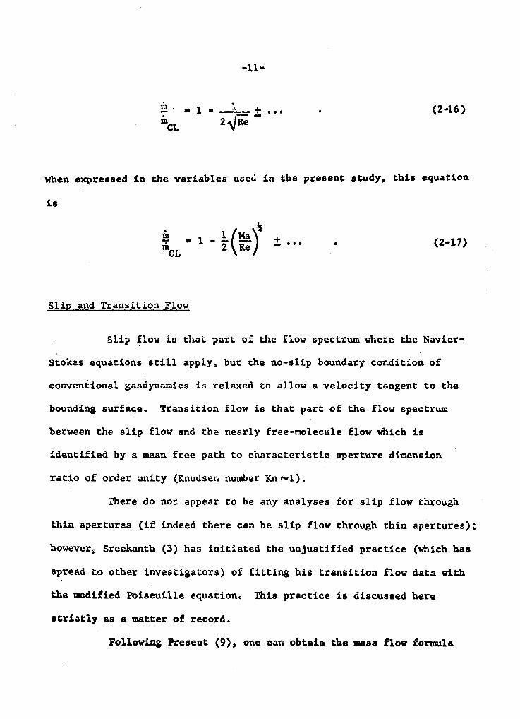
When expressed in the variables used in the present: atudy, this equation
is
Slip and Transition Flow
Slip flow is that part of the flow spectrwn where the Navier-
Stokes equations still apply, but the no-slip boundary condition of
conventional gasdynamics is relaxed to allow a velocity tangent to the
bounding surface. Transition flow is that part sf the flow spectrum
between the slip flow and the nearly free-molecule flow which is
identified by a mean free path to characteristic aperture dimension
ratio of order unity (Knudsen number Kn-1).
There do not appear to be any analyses for slip flow through
thin apertures (if indeed there can be slip flow through thin apertures);
however, SreeAcanth (3) has initiated the unjustified practice (which has
spread to other investigators) of fitting his transition flow data with
the mdified Psiseuille equation, This practice is discussed here
etrietly aa a matter sf record.
Following Present ( 9 ) , one can obtain the nutee flow forumla

for slip flow in long circular tubes as
where D is the tube diameter, L is the tube length, = %(pl + p2) ,
AP ' P1 - P2s and B 1s a constant which is a functi~n of the
equation chosen to relate mean free path and viscosity.
For example, three common equations used to relate mean free
path and viscosity are
and 1
= zzp),
The B's associated with these relationships are respectively
and
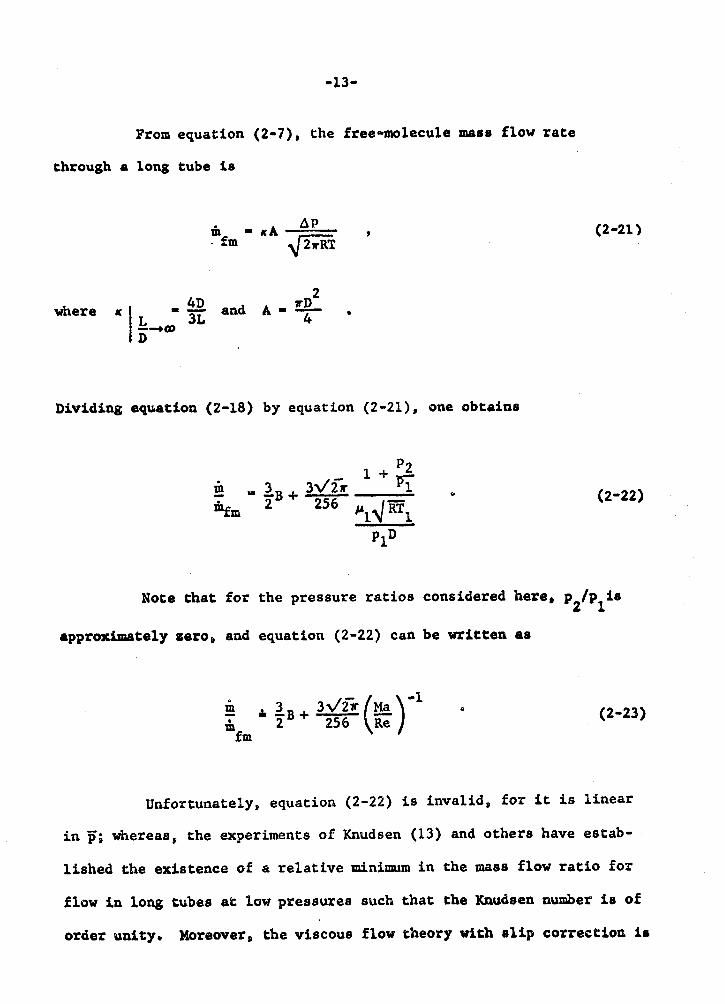
From equation (2-7), the free-molecule mass flow rate
through e long tube i e
4D L
where w = - and A - TA , 3L 4
Dividing equation (2-18) by equation (2-21), one obtains
Note that for the pressure ratios considered here /p is 'P2 I
approximately gero, and equation (2-22) can be written as
- P 0
i frn
Unfortunately, equation (2-22) is invalid, for it is linear
in p; whereata, the experiments of Knudsen (13) and others have estab-
lished the existence sf a relative minimum in the mass flow ratio for
flow in long tube8 at low pressures such that the Knudsen number is of
order unity. Moreover, the viscous flow theory with slip correetioa is

invalid for Knudsen number of order unity and, consequently, should not
be extrapolated into this region.
Sreekanth (3) found that he could fit his experimental data
for traneftion flow through circular orifices and short tubes LID^^)
with the right-hand side of equation (2-18) times the factor L/(L + D). In his work, he does not indicate what led him to this choice, nor does
he seem to grasp the significance of this parameter. Its relation to
the present analysis in equations (2-18) through (2-23) is best seen
when written as 1 - 1 - R I
When written in this form, one can easily note the effect of multiplying
the right-hand side sf equation (2-18) by L/(L 9 D) which is to approxi-
mate the Clausing factor for long tubes by D/L and the Clausing factor
for short tubes by 1/(1 + LID). The D/L representation is quite poor
(always 25% or more too small) since the Clausing factor for circular
geometries has the range 1-+4~/3L. The 1/(1 + LID) representation is quite good up to L/D of unity since, within this range, it never deviates
more than 3% from the true value sf the Cfausing factor. The success of
SreekanthPs mdPfied equation lies in the fact that most transition and
near free-molecule experimental mass flow data tend to am apparent
asymptote which is 3% to 6% higher than the free-molecule limit of
unity, and his modification "adjusts" the "theoretict~l'~ free-molecule
limit to 4/3 times 3 ~ / 2 (-1.047).

It is worthwhile to note that the leading term in equation
(2-23) for any of the B's of equations (2-20abc) is less than unity;
thus equation (2-23) does not even have the proper free-molecule limit
of unity. Considering the lack of rigor in the slip flow correction,
however, one might be tempted to set this leading term equal to unity.
Thus one has
Of course, this equation is no more valid than the one attributed to
Sreekanth, but it now has the same form as the valid solutions of the
near free-molecule flow regime which helps to explain the fascination
which some investigators have for this equation. equation
(2-25) to equations (2-8), (2-9), and (2-12). 1

111. APPARATUS AND TECHNIQUES
General Description
The apparatus used in this study of rarefied gas flow is a
continuous-flow, open-circuit facility which was designed and built
by Henderson (14) and McGill (15) to operate over a stagnation chamber
pressure range of 1 x to 5 x 10-I atmospheres while maintaining
a minimum 100:l pressure ratio across a test aperture of character-
istic dimension 1 x 10-' centimeters.
Figure 1 Is a photograph of the apparatus whose three main
component groups are shown schematically in Figures 2, 3, and 4. A
list of the equipment comprising the apparatus is given in Table I.
Since the schematics are largely self-explanatory, the following
paragraphs are devoted to the less obvious details and techniques.
Gas Feed and Flow Measurement
A11 experiments were performed with CIT grade helium taken
from standard cylinders. No particle filters were used, but conden-
sable gases were removed by the use of a liquid nitrogen cold trap.
The constant temperature bath was adjusted to maintain a nominal gas i
output temperature equal to that of the almost-constant temperature
sf the air-conditioned laboratory.
Two different types of volumetric flow meters were used
depending upon the flow rate. For flow rates less than 1 or 2 ce/sec, 8
the vol-u-meter was used. For flow rates greater than P or 2 cclsec,


G - GAS CYLINDER
VENT
TO NATION
CHAMBER
R, - HIGH PRESSURE REGULATOR R,- LOW PRESSURE REGULATOR C, - LIQUID NITROGEN TRAP .B - CONSTANT TEMPERATURE BATH
Te - TEMPERATURE WELL
p' - PRESSURE TAP 5 - ROTAMETERS F2 - VOL- W -METER P - PRESSURE TAP 6 b - VARIABLE LEAK
Figure 2. Gas feed and flow measurement schematic


STOKES 412 H EXHAUST
HYPERVAC 25
EXHAUST
Figure 4. Pumping schematic

Item - gas cylinders
pressure regulators
liquid nitrogen cold traps
constant temperature bath
vacuum flasks
themmeters
barometer
TABLE I
LIST OF EQUIPMENT
Description
2000 psig cylinder of research grade helium of purity 2 99.99%
2000 psig cylinder of nitrogen
Matheson model IL delivery pressure 3 to 80 psig
Matheson model 2 delivery pressure 25 to 650 psig
Matheson model 78B delivery pressure 3 to 15'' H2B gage
Greiner Glassware double-tube trap 30 crn Bong
ten-gallon jar of water with thermostatically controlled resistance heater
Thermos model 8640
ASTM Saybolt viseosity'#l7~ range 66 to 80°F Beast count 2 F"
Central Scientific range -10. to 91200F least count 2 F"
Central Scientific
Brooks range 0 to 25 cc accuracy .2% sf indicated volume
Stokes model 412H CENCB hypervac 25 W C PMCS-2@

TABLE I (continued)
Item - dial gages
manometers
rotameters
t imer
variable leak
thermistop gage
Mckeod gages
Description
Burton model 2311-001 range 0 to 15 psia least count .1 psi
Wallace and Tiernan model FA-233111 dual range 0 to 25, 25 to 50 psia least count .05 psi
Wallace and Tiernan model FAR 160 range 0 to 50 mm Hg least count -2 mm Hg
Wallace and Tiernan model FA 135 range 0 to 800 m Hg
Brooks E/c meters models R-2-15M with stainless steel float, R-2-25D with sapphire float, R-2-25A with sapphire float, and R-2-25B with sapphire float least count .1 mm
Standard range O to 1000 sec least count . I see
Granville-Phillips model 283 range 10-10 cc/sec to lo2 cc/sec with 1 atm pressure differential
CVC model GTC-100 range 0-1000 Hg
Greiner Glassware non-linear model range 0 to 125VHg
linear model ranges 0 to 1 m Hg, 0 to 10 mm Hg, and 0 to 100 nmn Hg

one of four rotameters was used. The rotameters, which are continuous-
flow devices, were calibrated for helium using the water displacement
Q method. When measuring low flow rates, the vol-u-meter--a positive
displacement device--was bypassed until steady state conditions were
attained. At this time it was switched into the circuit to measure the
volumetric flow rate. Since this increased the pressure drop across
the flow meters, the steady state conditions previously attained were
disturbed. A technique whereby one of the rotameter needle valves was
used ts increase the pressure drop across the flow meters when the
Q vol-u-meter was bypassed, and was switched out of the circuit when the
8 vol-u-meter was switched in, appeared to correct this disturbance.
The precision stainless steel needle valve, used to throttle
the gas into the stagnation chamber of the vacuum vessel, had a three
digit counter attached to the drive handle. Each digit in the unitgs
position of the counter corresponded to 1/10 turn of the needle valve
which required 27 full turns to go from fully open to fully closed
conductance. This counter was used as an aid in repeating an experi-
mental point.
Vacuum Test Vessel
The vacuum test vessel is a steel cylinder with end plates
and a bulkhead which: divides the tank into two chambers. Each chamber
measures 40 cm on the internal diameter. The upstream chamber is 40 cm
long; the downstream chamber is 50 cm long. The bulkhead has a machined

opening which can accommodate various size test apertures. The
apertures are installed or inspected through a port in the upstream
stagnation chamber. Three penetrations are provided in the stagnation
chamber and two are provided in the exhaust chamber for gas inlet, gas
exit, temperature taps, and pressure taps. Considerable care was taken
in the selection of these locations so as not to bias the data.
Test Apertures
The circular orifice used in this study was machined from
steel plate, inspected on an optical comparator, and fitted flush into
the upstream surface of the dividing bulkhead of the vacuum test vessel.
Considering the fact that the diameter of the orifice is 1 x 10-I cm
and the internal diameter of the vacuum test vessel is 40 cm, the tank
walls do not have any effect on the flow. Figure 5 is a detail drawing
of the circular orifice which was used in the present study. The
Clausing factor for this geometry is 0.918, and it was obtained from
ClausingPs (10) original work using the dimensions given in Figure 5.
Several slits were chemically milled in 0.002-inch thick
beryllium-copper and inspected on an optical comparator. The slit
chosen for use was approximately rectangular when observed under 20X
magnification, Because of the method of construction, the slit had no
sharp corners. Based on the actual flow area, it effectively measured
0.0038 inches by 0,35 inches. The flow area of the slit increased very
slightly from one side to the other (the slit was acid etched from one
side only), so it was used with the flow area increasing in the


direction of the flow. The Clausing factor for the slit is 0.6, and
it was calculated, assuming rectangular geometry, from formulas in
Clausing's (10) original work using the effective dimensions. Even
after making allowance for the divergence of the flow area, there is
still a greater uncertainty in the slit Clausing factor than in the
orifice Clausing factor. Figure 6 shows the effective dimensions of
the slit which was used in the present study, the adapter plate, and
the manner in which the slit was mounted.
Pumping
The parallel pumping arrangement allows a rapid evacuation
of the vacuum test vessel to the 1 x loe6 atmosphere range by use of
the large mechanical pump. During this time, the oil diffusion pump
is isolated while being warmed to operating conditions. There is no
provision for controlling the backstreaming of the pump oils. .
Vacuum Pressure Measurement
Stagnation chamber pressures can be measured by either of two
McLeod gages, a mechanical gage, a mercury manometer, or a thermistor
gage, depending upon the pressure range. The McLeod gages are the
primary standards, and the other instruments are calibrated to agree
with them; however, the thermistor gage is only used for pressure
monitoring. The exhaust chamber pressure can be measured by either of
the same two McLeod gages or a thermistor gage. As before, the
thermistor gage is used only for monitoring pressure. All pressure


measurements involving mercury columns were corrected to O'C and
standard gravity.
Seals, Leaks and Outgassin&
Extensive use was made of O-ring and glassblown seals in
the construction of the apparatus. Where such seals were not used,
(i3 the joints were coated with epoxy or painted with glyptal. After the
installation or inspection of the test apertures, the vacuum test
vessel was pumped to the micron range and held there for several weeks
in order to reduce the effects of outgassing. The ultimate leak plus
outgassing thus obtained would raise the tank preseure from am Hg
by approximately .3r/hr. For all but the smallest flow rates, this
pressure rise was entirely negligible.
Each of the plotted points is an average of three or more
measurements at the same setting of the precision needle valve and
represents a separate measurement of the volumetric flow. The
estimated error from known sources, such as the volumetric flow
measurements, room temperature variation, and aperture geometry, is
about - -1- 2% for the orifice and about 2 5% for the slit. Additional
errors, which are difficult to estimate, arise from such things as
uneven outgassing, lack of attainment of steady flow, and the inherent
difficulties involved in using and reading a McLeod gage,

-29-
IV. DISCUSSION OF RESULTS
The method of data reduction selected for use is similar
to that introduced by Liepmann (1). A characteristic velocity, Mach
number, and Reynolds number are defined as
and
Using the ideal gas equation of state, equation (2-6), these terms
can also be written as
and

For the large pressure r a t i o s used i n t h i s experiment, and i n the
experiments and theory t o which it is compared, theee terms are
approximately
and
The charac ter i s t ic dimension of the c i rcu la r o r i f i c e and of
the two-dimensional s l i t i s based on the r a t i o of aperture area t o
apermre perimeter. Thus, one has for the c i rcu la r o r i f i ce ,
D*
and for the' slit ,
where b is the r a t i o of the short: s ide of the s l i t t o the long side h
of the slit. In theae experiments, << 1. Note that the r a t i o of ii
Mach number t o Reyaolde number,

is proportional t o the Knudsen number,
but it avoids the ambiguity associated with the definit ion of a mean
free path.
Ae g Q D , the theoretical l i m i t for each geometry is Re
1 i m i t $ - 1 .
A S % - O the theoretical l i m i t for each geometry i s given by Re

Note that this limit, as defined, is a function of the aperture
p2 geometry ( K ) , the pressure ratio - , and the molecular complexity of P,
the gas ( 7 ) ; whereas the free-molecule flow limit, as defined, is
independent of such factors and a.
Except for one figure, which is plotted as the ratio of
measured mass flow to theoretical continuum limit mass flow versus the
ratio of Mach number to Reynolds number, the results of the present
investigation and the results of previous investigators are plotted as
the ratio of measured mass flow to theoretical free-molecule mass flow
versus the ratio of Mach number to Reynolds number.
Figure 7a shows the present experimental data for the circular
orifice and the two-dimensional slit. Note how the dimensionless mass
flow for each aperture levels off near = 10' as the free-molecule Re
flow limit is approached. Since the data levels off well above the
theoretical limit of unity, there is probably some systematic error
here which involves the flow area, the Clausing factor, and the pressure
difference across the apertures; yet, it is interesting to note that the
original data of Knudsen (13), when corrected for finite aperture thick-
ness by Liepmann (I), are about 7% greater than the limiting value in
this region. In addition, although Sreekanth (3) used very precise
instrumentation and a circular orifice 1 inch in diameter in 0.005-inch
thick copper, even his data are 4% greater than the limiting value in
this region. According to the theoretical calculations on nearly free-
molecule flow, however, the mass flow ratio should be within 2% of its
limiting value in this region. There is no very satisfactory explanation


for this behavior other 'than the factors mentioned above. For values
of < 5 x the data for the orifice and the slit diverge greatly. Re
One should expect this behavior because of the large difference in the
continuum limits of the two apertures, a result of the greatly different
Clausing factors for the two apertures and the manner in which the
continuum limit is defined in equation (4-15). Since the Clausing
factor for the orifice used in the present investigation is 0.918, and
that for the slit is 0.6, other things being equal, one can see from
equation (4-15) that the defined continuum limit for the slit is
0.918/0.6 times that of the orifice.
Excluding the uncertainty in the difference between a for the
circular orifice and a for the two-dimensional slit, one might attempt
to infer that the difference in the dimensionless mass flow for an
orifice and a slit which have identical Clausing factors could be quite
small over the whole flow spectrum. That this inference is invalid is
easily seen when one examines Figure 7b where the experimental mass flow
of the present investigation is made dimensionless, using the theoretical
continuum-limit mass flow. This figure vividly illustrates the fact
that there is quite a difference in the flow through a circular orifice
and a two-dimensional slit. Probably the most striking difference to be
noted in Figure 7b is in the approach to the continuum limit. For values
of of order 10'~ the orifice mass flow is within a few percent of the Re
continuum limit while the slit mass flow is very far away from the con-
tinuum limit. A crude estimate, obtained by linear extrapolation in
Figure 7b, indicates that the slit flow will require values of Ma of Re


order in order to approach the continuum limit as closely as the
2 orifice flow does at values of Ma of order 10- . Re
Figure 8 compares the data of the present investigation with
the experimental data of Liepmann (I), Henderson (14), and McGill (15)
for orifice flow. The agreement is seen to be quite good in all
respects for > 5 x 10'~. As previously mentioned, the divergence Re
at the continuum end of the flow spectrum is due to the different
Clausing factors. The Clausing factor for Liepmann's orifice is 0.975
which places its continuum limit lower than that for the circular
orifice used by Henderson, McGi11, and the present investigator.
Figure 9 compares the data of the present investigation
with the theoretical calculations of Narasirnha (4) and Willis (2) for
the region near free-molecule flow ( - 2 1 ) . in this limited
range, the agreement is qualitatively good but quantatively poor, for
the experimental data levels off too high. One must remember that the
calculations of Narasimha and Willis are only valid for > 1; there- Re -
fore, they cannot be legitimately compared to the experimental data
outside this range.
Figure 10 compares the data of the present investigation with
the experimental data of Sreekanth (3) for orifice flow. Within the
limited range of Sreekanth's data, the agreement of his orifice flow
and that of the present investigator is quantitatively good and quali-
tatively excellent.
Figure 11 compares the data of the present investigation with
the experimental data of Smetana (6) and Lord (8) for orifice flow.


~metana's experimental data are shown, while ~ord's data are represented
by his best-fit curve. The agreement of the three sets of orifice data \
is fairly poor. It should be noted, however, that Lord's experimental
range is Ma 2 1. Therefore, his data should not be compared to other Re
date outside this range. Smetana's data do not appear to be corrected
for nonzero orifice thickness. If corrected for this effect, his
experimental points would be increased about 1%.
Figure 12 compares the data of the present investigation with
various forms of the modified Poiseuille equation equation (2-22) . [ This figure is included here strictly as a matter of interest and
I infomation, and one is directed to the section on Slip a d Traneition
Flow (pages 11-15) for all comments.


V . CONCLUSIONS
The experiments conducted on the circular orifice and the two-
dimensional slit show the trend of asymptotic approach to a limiting
value at each end of the flow spectrum, corresponding to the continuum
flow limit and the free-molecule flow limit. The transition from one
part of the flow spectrum to another is smooth, as attested to by the
smooth curves of dimensionless mass flow versus dimensionless rarefac-
tion parameter. The data of the present investigation, and that sf all
other investigations surveyed except one, show a mass flow, in the nearly
free-molecule part of the flow spectrum (lo0< M" PO^), which is greater Re
than that predicted by the theoretical analysis. As discussed on page
32, this is thought to be experimental error; yet, the disparity lies
outside the estimated limits of experimental error of each investiga-
tion. Future investigations will be necessary to resolve this question.
One of the most surprising aspects of the present investiga-
tion is the fact that the transition from near free-molecule flow to
near continuum-limit flow for the two-dimensional slit appears to cover
a much broader range of the flow spectrum than that required for the
circular orifice. The transition for the circular orifice appears to
be substantially complete within the range 1 0 ~ ~ ~ Mas 100 (see Figure Re
7b). The transition for the two-dimensional slit is roughly estimated
to cover the range -10-~<!%~10~ (see Figure 7b and the discussion on - Re page 34).
It is interesting to note how the leading term of equations
similar to equation (2-23) can be adjusted to give good agreement with

-44 -
the flow in the range Ma/~e >_ lo-'. The obvious reason for the success
lies, of course, in the fact that the first iterate of the rigorous
gaskinetic solution for this range is linear in (Ma/~e)-' as is equation
(2-23).
In conclusion, the flow of a rarefied gas through a thin
aperture of arbitrary geometry is worthy of further investigation.
Theoretically, one needs to determine a general formula for the a(r)
factor and to analyze the flow near the continuum limit. Experimentally,
one needs to get the apparent free-molecule limit to agree (at least
within the experimental error) with the theoretical free-molecule limit.

BIBLIOGRAPHY

BIBLIOGRAPHY
Liepmann, H. W. "Gaskinetics and Gasdynamics of Orifice Flow," Journal of Fluid Mechanics, Vol. 10, Part I (1961), 65-79.
Willis, D. R. "Mass Flow Through a Circular Orifice and a Two- Dimensional Slit at High Knudsen Numbers," Journal of Fluid Mechanics, Vol. 21, Part I (1965), 21-31,
Sreekanth, A. K. "An Experimental Investigation of Mass Flow Through Short Circular Tubes in the .Transition Flow Regime," Boeing Document Dl-82-0427, Boeing Scientific Research Laboratories (1965).
Narasimha, Roddam. "Orifice Flow at High Knudsen Numbers," Journal of Fluid Mechanics, Vol. 10, Part 3 (1961), 371-384.
Milligan, M. W. "Low-Density Gas Flow in Long Tubes," AIAA - Journal, Vol. 4, No. 4 (1966), 745-746.
Smetana, F. 0. "Measurements of the Discharge Characteristics of Sharp-Edged and Round-Edged Orifices in the Transition Regime," Rarefied Gas Dynamics, Vol. I1 (1967), 1243-1256.
Carley, C. T., Jr. "Experiments on Transition Regime Flow Through a Short Tube with a Bellmouth Entry," AIAA Journal, Vol. 4, No. 1 (1966), 47-54.
Lord, R. G. "Nearly Free Molecule Flow Through a Circular Orif ice at High pressure Ratios ,I1 ~aref ied- as Dynamics, Vol. II (1967), 1235-1242.
Present, R. ID. Kinetic Theory of Gases. New York: McGraw-Hill, 1958.
Clausing;, B. %er die Str6mung sehr verdunneer Gase durch Rohren von beliebiger Lange,Is Ann. Physik, VoP. 12 (1932), 961-989.
Guderley, K. G. Theorie schallnaher StrBmungen. Berlin: Springer- Springer-Verlag, 1957.
Frankl, F. I . "The Discharge of a Supersonic Jet from a Vessel with Plane Walls," Reports of the Academy of Sciences USSR, Vol. 58, No. 3 (1947), 381-384. (In Russian)

13. Knudsen, M. "Die Gesetze der MolekularstrBmung und der inneren Reibungsstromung der Gase durch RLlhren," Ann. Physik, Vol. 28 (1909), 75-130.
14. Henderson, A. H. "Construction and Testing of a Rarefied Gas Flow Facility." Aeronautical ~ngineer's thesis, California Institute of Technology, Pasadena, 1967.
15. McGill, J. A. "Low-Density Gas Facility." Aeronautical Engineer's thesis, California Institute of Technology, Pasadena, 1967.