the foundation of electromagnets based active vibration control
TRANSCRIPT

2
The Foundation of Electromagnets Based Active Vibration Control
Ramón Ferreiro García, Manuel Haro Casado* and F. Javier Perez Castelo University of A Coruña, University of Cadiz*
Spain
1. Introduction
Turbines, pumps, compressors, blowers and all rotating machinery in general, is commonly used in process industry, including machining tools, power generation, as well as aircraft and marine propulsion among the most important industrial applications. Mass imbalance is commonly responsible for rotating machinery vibration. When the principal axis of inertia of the rotor is not coincident with its geometric axis imbalance occurs. Nevertheless there are some more causes for rotating machinery vibration such as operation near resonant frequencies, critical speeds and so on. Higher speeds cause much greater centrifugal imbalance forces, and the current trend of rotating equipment toward higher power density clearly leads to higher operational speeds. For instance, speeds approaching 35,000 rpm are common in machining applications. Therefore, vibration control is essential in improving machining surface finish; achieving longer bearing, spindle, and tool life in high-speed machining; and reducing the number of unscheduled shutdowns. A great cost savings for high-speed turbines, compressors, and other turbomachinery used in petrochemical and power generation industries can be realized using vibration control technology. Passive and active vibration control (AVC) techniques of rotating machinery are being used. It is well established that the vibration of rotating machinery can be reduced by introducing passive or active devices into the system. Although an active control system is usually more complicated than a passive vibration control scheme, an AVC technique has many advantages over a passive vibration control technique. In (Fuller et al., 1996) it is shown that AVC is more effective than passive vibration control in general. Furthermore, the passive vibration control is of limited use if several vibration modes are excited. Finally, because the active actuation device can be adjusted according to the vibration characteristic during the operation, the active vibration technique is much more flexible than passive vibration control. There are two major categories in AVC techniques for rotating machinery:
• Direct active vibration control (DAVC) techniques in which directly apply a lateral control force to the rotor.
• Active balancing techniques which adjust the mass distribution of a mass redistribution actuator. Active balancing isn’t under the scope of this chapter.
The control variable in DAVC techniques is a lateral force generated by a force actuator based on a magnetic bearing. The advantage of DAVC techniques is that the input control force to the system can be changed according to vibration characteristics.
Source: Vibration Control, Book edited by: Dr. Mickaël Lallart, ISBN 978-953-307-117-6, pp. 380, September 2010, Sciyo, Croatia, downloaded from SCIYO.COM
www.intechopen.com
Vibration Control
34
By applying a fast changing lateral force to the rotating machinery, the total vibration, including the synchronous vibration, the transient free vibration, and other nonsynchronous vibration modes of the rotating machinery, can be attenuated or suppressed. The limitation of most force actuators is the maximum force they can provide. In high rotating speed, the imbalance-induced force could reach a very high level. As most force actuators cannot provide sufficient force to compensate for this imbalance-induced force, active balancing methods are well justified. Although active balancing methods can eliminate imbalance-induced synchronous vibration, they cannot suppress transient vibration and other nonsynchronous vibration. In this chapter DAVC techniques are introduced. Since the mathematical model is the foundation of any AVC technique, a description of dynamic modelling techniques applied on rotating machinery is included.
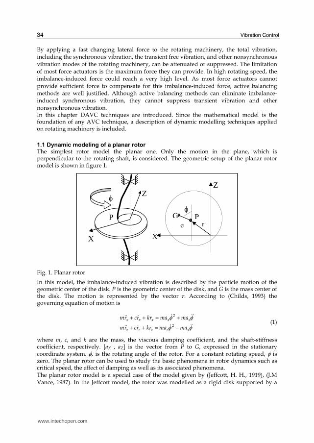
1.1 Dynamic modeling of a planar rotor The simplest rotor model the planar one. Only the motion in the plane, which is perpendicular to the rotating shaft, is considered. The geometric setup of the planar rotor model is shown in figure 1.
Fig. 1. Planar rotor
In this model, the imbalance-induced vibration is described by the particle motion of the geometric center of the disk. P is the geometric center of the disk, and G is the mass center of the disk. The motion is represented by the vector r. According to (Childs, 1993) the governing equation of motion is
2
2
x x x x z
z z z z x
mr cr kr ma ma
mr cr kr ma ma
φ φφ φ
+ + = ++ + = −
$ $$$$ $$ $$$$ $
(1)
where m, c, and k are the mass, the viscous damping coefficient, and the shaft-stiffness coefficient, respectively. [aX , aZ] is the vector from P to G, expressed in the stationary coordinate system. φ, is the rotating angle of the rotor. For a constant rotating speed, φ is zero. The planar rotor can be used to study the basic phenomena in rotor dynamics such as critical speed, the effect of damping as well as its associated phenomena. The planar rotor model is a special case of the model given by (Jeffcott, H. H., 1919), (J.M Vance, 1987). In the Jeffcott model, the rotor was modelled as a rigid disk supported by a
X
P
Zφ
re
φG P
X
Z
www.intechopen.com

The Foundation of Electromagnets Based Active Vibration Control
35
massless elastic shaft that was mounted on fixed rigid bearings. This model is also equivalent to a rigid shaft supported by elastic bearings. The major improvement over the simple planar rotor model is that the motion of the rotor is depicted by rigid body motion instead of by particle motion. Although this model is a single rigid body model, it ca be shown the basic phenomena in the motion of the rotor, including the forward and backward whirling under imbalance force, critical speeds and the gyroscopic effect.
Fig. 2. Rigid Rotor Model
Due to the fact that the natural frequency is a function of the rotating speed, it can also be predicted by this model. The geometric setup of this model is shown in figure 2. In this setup, bearings are modelled as isotropic linear spring and damper. The imbalance is
modelled as concentrated mass on the rigid shaft. Two coordinate systems are used: the
body-fixed coordinate oxyz and the inertial coordinate OXYZ. The body-fixed y-axis is the
rotating axis of the shaft, and x and z axes are defined by the other two principal inertia axes
of the rotor. The origin of xyz is selected as the geometric centre of the shaft. The XYZ
coordinate system is the stationary coordinate which is coincident with the xyz coordinate
system under body rest condition. The transverse motion of the rotor is described by the
position of the geometric centre [RX RZ] and by the orientation of the rigid shaft with
respect to the X and Z axes [φ, ψ]. A simplified state space governing equation is shown in
(2) (Zhou & Shi, 2000):
2 2
2 2
0 0 0 0 1 0 0 0
0 0 0 0 0 1 0 0
0 0 0 0 0 0 1 0
0 0 0 0 0 0 0 1
2 20 0 0 0 0 0
2 20 0 0 0 0 0
0 0 0 02 2
0 0 0 01 2
x
z
x
z
p p
t t t t
p p
t t t t
R
R
k c
m mdk cRdt
m mRI IkL cL
I I I I
I IkL cL
I I I I
φ φφ φ
⎡ ⎤⎢ ⎥⎢ ⎥⎡ ⎤ ⎢ ⎥⎢ ⎥ ⎢ ⎥⎢ ⎥ ⎢ ⎥⎢ ⎥Θ ⎢ ⎥⎢ ⎥ ⎢ ⎥− −Ψ⎢ ⎥ ⎢ ⎥=⎢ ⎥ ⎢⎢ ⎥ − −⎢⎢ ⎥ ⎢⎢ ⎥ ⎢⎢ ⎥Θ ⎢ − −⎢ ⎥ ⎢Ψ⎢ ⎥⎣ ⎦ ⎢⎢ − − −⎢⎣ ⎦
$
$$$ $$
$$$ $
1
2
0 0
0 0
0 0
0 0
x
z
u z u x
x u x u z
z
u z y u y z
t t
u y z u x y
t t
R
R
m u m u
fm mR m u m u f
m mRm u u m u u
I I
m u u m u u
I I
⎡ ⎤⎢ ⎥⎢ ⎥⎡ ⎤ ⎢ ⎥⎢ ⎥ ⎢ ⎥⎢ ⎥ ⎢ ⎥⎢ ⎥Θ ⎢ ⎥−⎢ ⎥ ⎢ ⎥Ψ⎢ ⎥ ⎡ ⎤⎢ ⎥+⎢ ⎥ ⎢ ⎥⎥ ⎢ ⎥⎢ ⎥ ⎣ ⎦⎥ ⎢ ⎥⎢ ⎥⎥ ⎢ ⎥⎢ ⎥⎥ ⎢ ⎥⎢ ⎥Θ⎥ ⎢ ⎥⎢ ⎥⎥ ⎢ ⎥Ψ⎢ ⎥⎣ ⎦⎥ ⎢ ⎥−⎥ ⎢ ⎥⎥ ⎢ ⎥⎣ ⎦
$
$
$$
(2)
mu
z
y
Y
Z
uy
X
x
www.intechopen.com

Vibration Control
36
where L is the length of the shaft; Ip and It are the polar and the diametric moments of inertia of the shaft, respectively; mu, ux, uy, uz are the mass and the position of the imbalance in body-fixed coordinate. Exciting forces are defined as:
2 21 2cos( ) sin( ), sin( ) cos( )f fφ φ φ φ φ φ= ⋅ = ⋅$$ $ $$ $ (3)
The model given by (2) can be used on most of the shafts provided that the rigidity of the shaft is high compared to the supporting bearing. For analysis, simulation and control objectives the proposed model is considered sufficiently accurate When flexible rotor models are applied, more complicated rotor system models must be developed. Such models allows for the elastic deformation of the rotor when in rotation. Consequently, it is more accurate than the rigid rotor model. A complicated rotor system is divided into several kinds of basic elements: rigid disk, bearing, flexible shaft segments, couplings, squeeze-film dampers, and other needed accessories. The equations of motion for each of these components can be developed using the appropriate force-displacement and force-velocity relations and the momentum principles as well as other equivalent dynamic relations. From the above review on rotor dynamics, it is concluded that many powerful tools for the linear system and frequency response are available. However, most of these techniques are targeted at the rotor design analysis. It has been mentioned that for an efficient AVC system synthesis, a suitable analytical model must be used which is simple in comparison to the overall system equations, while still providing the essential dynamic characteristics. (Maslen & Bielk, 1992) presented a stability model for flexible rotors with magnetic bearings. Besides the flexible rotor model itself, their model included the dynamics of the magnetic bearing and the sensor-actuator noncollocation. This model can be used for stability analysis and active vibration synthesis. Most recently, an analytical imbalance response of the Jeffcott rotor with constant acceleration was developed by (Zhou & Shi, 2001). They concluded that a satisfactory solution quantitatively shows that the motion consists of three parts:
• the transient vibration at damped natural frequency,
• the synchronous vibration with the frequency of instantaneous rotating speed,
• and a suddenly occurring vibration at damped natural frequency. Such mentioned technique provides physical insight into the imbalance-induced vibration of the rotor during acceleration. For this reason it can be used for the synthesis of AVC schemes. For the synthesis of DAVC techniques, most it is common to use simplified low-order finite element models of the rotor system. Although the techniques developed can be extended to a high-order system theoretically, the computational load and consequently the signal-to-noise ratio will have to be higher. The DAVC techniques can be difficult to implement for the high-order system. Therefore, it is conveniently to use a reduced order models to approximate the high-order system models. Applied model reduction techniques have a specific impact on the performance of the DAVC schemes that must be considered if expected performance cannot be achieved.
1.2 DAVC for rotating machinery
AVC for rotating machinery is considered a special case of AVC for a flexible structure. The general topic regarding AVC was discussed by (Inman and Simonis, 1987) and (Meirovitch,
www.intechopen.com

The Foundation of Electromagnets Based Active Vibration Control
37
1990). The difference between rotating machinery and other flexible structures is that the dynamics of the rotor changes with the rotating speed of the shaft. Best control performance could be achieved if control gains vary with rotating speed. Also, because the shaft is a moving part, a noncontact actuator is used to apply the control force to the rotating shaft. There are many types of actuators for direct AVC, including electromagnetic, hydraulic and piezoelectric as the most important ones. The active magnetic bearing (AMB) is an established industrial technology with a rapidly growing number of applications. A good example of the application of magnetic bearings in the machine tool industry can be found in (Bleuler et al., 1994). AMB can be used to apply a synchronous force to the shaft to control the imbalance response, either to cancel the force transmitted to the base or to compensate for the vibration displacement of the shaft. In (Knospe et al., 1996; Knospe et al., 1995; Knospe, Tamer, & Fittro, 1997; Knospe, Tamer, & Fedigan, 1997) presented an adaptive open-loop control method for the imbalance displacement vibration control using AMBs. A synchronous force that consists of sinusoids that are tied to the shaft angular position via a key phasor signal was generated and applied to the rotor through the magnetic supporting bearings. The magnitude and phase of these sinusoids were periodically adjusted so as to minimize the rotor unbalance response. The magnetic bearings were used to emulate the imbalance-induced force to offset the force induced by the system imbalance. Therefore, Knospe and colleagues’ methods are called “active balancing” methods rather than “DAVC” methods. Other researchers such as (Herzog et al., 1996) and (Lum et al., 1996) published their work on the imbalance transmitted force controlled by magnetic bearings. The basic idea is to use a notch filter to blind the control system of the supporting magnetic bearing to the imbalance induced response. Therefore, no synchronous forces can be generated by the magnetic bearings. The rotor will then rotate about its own principal inertia axis provided that the gap between the shaft and the bearing is large enough. (Fan et al., 1992) presented a vibration control scheme for an asymmetrical rigid rotor using magnetic bearings. Other researchers working in DAVC for rotating machinery adopted a state space representation of a rotor system. The control inputs are lateral forces. (Balas, 1978) pointed out that for a feedback control system for flexible systems, the control and observation spill-over due to the residual (uncontrolled) modes could lead to potential instabilities. In (Stanway & Burrows, 1981), the dynamic model of the flexible rotor was written in the state space format and the controllability and observability of the model were studied. Stanway and Burrows concluded that the lateral motion of the rotor can, under certain conditions, be stabilized by the application of a single control input to a stationary component. (Ulsoy, 1984) studied the characteristics of rotating or translating elastic system vibration problems that are significant for the design of active controllers. The basic conclusions of his research were that a controller gain matrix that is a function of the rotating speed is required to maintain a desired closed-loop eigenstructure and that a residue model spill-over should be handled carefully by the active controller to avoid instability. (Firoozian & Stanway, 1988) adopted a full-state observer technique to design a feedback AVC system. The stability of the closed-loop system was also studied. To build an AVC system for flexible structures, the sensor/actuator deployment is an interesting topic. The issue of
www.intechopen.com

Vibration Control
38
actuator/sensor placement for control of flexible structures is an active research area. This problem is often formulated as a constraint optimization problem. The constraints of this optimization problem are the limited available locations for the actuators and sensors. The objective function of this optimization problem is closely related to the control algorithm used for the flexible structure. The main possible optimal cost functions for sensor and actuator placement are for system identification, state estimation (which is represented by the observability) and indirect control performance (which is represented by the controllability), and direct control performance (e.g., the transient response, stability).
1.3 Discussion about DAVC
Since rotating machinery is widely used in industry, the AVC of the rotating machinery is an important engineering problem for both industry and academia. In this introductory section, a review of the direct vibration control for rotating machinery was conducted. The major problem faced by the AVC scheme is the use of a limited number of actuators to control an infinite number of vibration modes. To design an active control scheme, a reduced-order model should be used and the effect of the spill-over of higher vibration modes assessed. Although the available techniques developed for dynamic analysis and active real-time vibration control can be extended to high-order systems theoretically, the computational load will be heavier and the signal-to-noise ratio of the vibration measurement will have to be higher. Hence, the available techniques could be difficult to implement in high-order systems. Consequently, it is necessary to use a model reduced system to approximate the high-order system. In most of AVC methods, the imbalance estimation is coupled with the control strategy. So far, there are no systematic methods available to show the relationship between the estimation and the control strategy. A control action is preferable if it can obtain small imbalance-induced vibration and excite the system to obtain the good imbalance estimation at the same time. Thus, coupling effects should be investigated by considering the estimation algorithm, the system dynamics, and the control performance. This research can also lay a scientific foundation for the design of an efficient and reliable generic adaptive control system. It is clear that the active balancing can improve product quality and improve the fatigue life of the machine and cutting tools and, hence, reduce the system cost. However, the installation and maintenance of an active vibration system for rotating machinery will increase the system cost. How to assess the AVC system from a cost-effective point of view and on a higher process level is not well studied in the literature. More that two decades of experience demonstrates that this is an interesting and important problem in the AVC of rotating machinery.
2. AVC with magnetic actuators
2.1 Introduction
Unbalance response is a common vibration problem associated with rotating machinery. During several years, researchers have demonstrated that this vibration could be greatly alleviated for machines using active magnetic bearings through active magnetic control. Many of the control strategies employed fall into a class which the authors have termed adaptive open loop control.
www.intechopen.com

The Foundation of Electromagnets Based Active Vibration Control
39
Active magnetic bearings provide a number of advantages over conventional bearings for a variety of practical industrial applications. These include elimination of the lubrication system, friction free operation, decreased power consumption, operation at temperature extremes, and vibration control. Recently there has been a great deal of interest in digital control of magnetic bearing systems. Digital control offers several major benefits for magnetic bearing supported rotors:
• quick tuning of a magnetic bearing system during installation
• implementation of some simple but powerful control strategies, such as gain scheduling
• application of fault tolerant controller architectures
• built-in monitoring and diagnostic capabilities As the results shown along a couple of years indicate, digital control provides capabilities
for adaptive control which can be used to greatly alleviate the unbalance vibration of
rotating machinery. This is often the worst vibration problem encountered during operation.
The source of this vibration is the discrepancy between the geometric axis of the rotor and
its inertial axis. When the rotor is spinning, this imbalance results in a centrifugal force
which causes synchronous vibration throughout the machine. This problem is managed on
conventional machinery through mechanical balancing by means of the addition or removal
of a small amount of mass from the shaft to reduce the residual imbalance. Rotor balancing
in the field, unfortunately, is usually time consuming and costly. The down-time incurred
can also be very expensive in terms of lost production. Also for some machines where the
imbalance changes often during operation, such as centrifuges, mechanical balancing will
have a limited benefit.
Magnetic bearings, being active devices, offer the capability to establish new and beneficial
relationships between rotor and casing vibration and applied bearing force.
This capability has been employed by a considerable number of researchers investigating
the control of unbalance response. One method to achieve unbalance response attenuation is
through design of the feedback compensation. This has been achieved via the addition of
filters to stabilizing controllers (Habermann & M. Brunet, 1994), (Larsonneur & R. Herzog,
1994) or through the addition of pseudo-states in observer based controllers (T. Higuchi, T.
Mizuno, & M. Tsukamoto, 1990), (F. Matsumura, M. Fujita, & K. Okawa, 1990). Other
researchers (C.R. Burrows & M.N. Sahinkaya, 1983), (C.R. Burrows, M.N. Sahinkaya, & S.
Clements, 1989), (T. Higuchi et al., 1990), (R. Larsonneur, 1988), (Larsonneur & R. Herzog,
1994), (B. Shafai et al., 1994), (C.R. Knospe et al., 1993), have employed methods which the
authors refer to as adaptive open loop control. These methods, as pointed out by (R.
Larsonneur, 1988), (Larsonneur & R. Herzog, 1994) and Shafai et al., 1994), have the
advantage that they may be added to feedback controllers that have been designed for
optimum transient response without altering system stability or performance. These
methods were first employed on a magnetic bearing supported rotor by (C.R. Burrows &
M.N. Sahinkaya, 1983) who solved a least-squares-balancing problem for the proper forces
to apply using an off-line theoretical model. They later extended this work to obtain an
estimate of an influence coefficient matrix through trial forces and the use of a recursive
control law (C.R. Burrows, M.N. Sahinkaya, & S. Clements, 1989). (Higuchi et al., 1990)
applied an adaptive open loop method (periodic learning control) employing an estimate of
the inverse transfer function in a recursive procedure. This method can only be applied on
systems with square influence coefficient matrices (number of actuators equals number of
www.intechopen.com
Vibration Control
40
vibration sensors). Following references (C.R. Burrows, M.N. Sahinkaya, & S. Clements,
1989), (Higuchi et. al., 1990) are very similar to the convergent control algorithm presented
by Knospe et al., 1993) which uses a look-up table of influence coefficients obtained through
off-line testing. Shafai et al., 1994) apply a distinct method of adapting the open loop forces
to cancel a synchronous signal. In such a method, only one Fourier coefficient of the open
loop signal is changed per adaptation cycle in such a mode as to decrease the residual error.
This method, originally developed for SISO systems, was extended to square MIMO
systems. Stability and performance robustness of this method (convergence to optimal open
loop control) is ensured. This is in contrast to most of the model-based methods where
stability and performance robustness is being studied now. The transient performance of the
adaptive open loop algorithms to changes in imbalance or rotor speed has to be considered
because of its practical importance
2.2 The test environment
This section presents the test environment for active vibration control of rotating machinery.
The principal idea is to control bending vibrations of a flexible rotor, supported by AMBs
based on two sets of non-contacting electromagnetic actuators located at both shaft ends as
shown in figure 3.
The test environment is composed of the following parts; a rotor test rig, two sets of
magnetic actuators assembled to operate as both electromagnetic actuators and AMBs, and a
programmable control unit (C.R. Fuller, S.J. Elliot, & P.A. Nelson, 1996), (C.R. Knospe, et al.,
1997), (S.J. Elliot, 2001) to be applied on vibration attenuation or vibration suppression by
means of feedback control applied to decrease the dynamic response of the rotor assumed as
active magnetic dynamic damping. The main studies to be carried out on the described test
rig deals with the dynamic response in the range of velocities of interest, especially near the
resonant frequency region which can be reduced with a conventional velocity-feedback
controller, or alternatively feedback filtering based control (K. Tammi (a), 2003), (K. Tammi
(b), 2003).
The feedback force is derived from the displacement measurements, obtained from the eddy
current transducers approximately collocated with the actuators as shown in figure 3 and 4.
The use of a velocity feedback controller decreases the response of the rotor significantly.
The active control brings the possibility to run the rotor across the critical speed. A
feedforward system, based on an adaptive finite-impulse-response filter (K. Tammi (b),
2003), may also be designed to compensate disturbances caused by the mass imbalance if a
reliable model of imbalance is available.
As shown in figure 4, every degree of freedom to be controlled requires a feedback control
loop. The control system applies the force commands to attenuate shaft vibration while
keeping the shaft into the radial position centre. The implementation of a shaft end vibration
and position control scheme is shown in figure 5. It consists in an Agilent Technologies
based hardware programmed under Matlab-Simulink V.9(a).
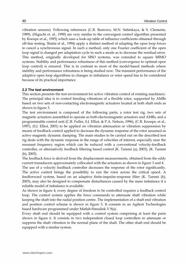
Every shaft end should be equipped with a control system comprising at least the parts
shown in figure 6. It consists in two independent closed loop controllers to attenuate or
suppress the shaft vibration in the normal plane of the shaft. The other shaft end should be
equipped with a similar system.
www.intechopen.com

The Foundation of Electromagnets Based Active Vibration Control
41
Fig. 3. The rotor-actuator system in two planes which must be controlled by two control loops because of the two degrees of freedom.
Fig. 4. Basic control loop.
AVC
Position command
Electro- magnets
Mechanical system
Eddy current based position sensors
Current amplifiers
Shaft dusturbance
Output Data Input data
Eddy current based radial position probes Magnetic core Magnetic coil Ferromagnetic bush Non magnetic shaft Inertial load with mass imbalance Magnetic core Magnetic coil Ferromagnetic bush Eddy current based radial position probes Magnetic core Magnetic coil Ferromagnetic bush Non magnetic shaft Eddy current based radial position probes
www.intechopen.com

Vibration Control
42
Fig. 5. Control loops implementation for a shaft end, using Matlab_Simulink: (a), with independent control algorithms. (b), with coupled control algorithms.
2.3 Control loop hardware Control loops accessories such as data acquisition and final control elements or actuation devices are implemented with specifically designed hardware based components.
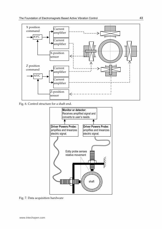
2.3.1 Data acquisition system Radial displacement is sensed by means of a data acquisition system which is based on a set of Eddy current probes. Axial displacement is measured under the same technology. Eddy Current Probe (ECP) systems are integral components, which typically consists of a non-contacting probe, an extension cable and a driver. An ECP typically senses mechanical movement and converts this movement (displacement) into a usable electrical signal. As shown in figure 7, the signal can be sent to a monitor system for condition monitoring, analysis and/or alarm protection as well as control applications.
2.3.2 Final control elements The final control elements composed by the magnetic field coils demand a large amount of current, which must be supplied by means of a Voltage Controlled Current Source (VCCS).
Loop_3
Loop_2
Loop_1
Loop_0
agilentu2300 0
U2353A
HWChannel0
HWChannel1
Analog Output
(Single Sample)1
agilentu2300 0
U2353A
HWChannel0
HWChannel1
Analog Output
(Single Sample)
agilentu2300 0
U2353A
HWChannel0
HWChannel1
Analog Input
(Single Sample)1
agilentu2300 0
U2353A
HWChannel0
HWChannel1
Analog Input
(Single Sample)
In1
In2
Out1
Out2
AVC_Algorithm
Loop1_2
In1 Out1
AVC_Algorithm
Loop1
In1 Out1
AVC_Algorithm
Loop0
www.intechopen.com
The Foundation of Electromagnets Based Active Vibration Control
43
AVC
X position command
X-position sensor
Current amplifier
Current amplifier
AVC
Z position command Current
amplifier
Current amplifier
Z-position sensor
Fig. 6. Control structure for a shaft end.
Driver Powers Probe:
amplifies and linearizes electric signal.
Monitor or detector:
Receives amplified signal and converts to user’s needs
Driver Powers Probe:
amplifies and linearizes electric signal.
Eddy probe senses relative movement
shaft
Fig. 7. Data acquisition hardware
www.intechopen.com

Vibration Control
44
The figure 8 shows the current amplifiers structure for a set of two opposite coils, capable for perform control forces in a single degree of freedom. The controller output provides a voltage based signal. Voltage to current conversion is performed by means of a VCCS. The VCCS can be useful for applications such as active loads for use in torque or force control servomotors. Force control is simplified since force is a direct function of current in an inductive load, such the applied coils. Figure 8 illustrates the basic circuit of a VCCS for a floating load. The load is actually in the feedback path. R1 and R2 are current sense resistors that develops a voltage proportional to load current.
D1
D2
0
R2
-VCC
+VCC
U2
+1
-2
V+5
V-3
OUT4
R3
1k
R4
0
0
L1
1
2
L2
1
20
R1
+VCC
Vcontrol
-VCC
U1
+1
-2
V+5
V-3
OUT4
Fig. 8. The current amplifiers structure for two opposite coils
2.4 Force current model for electromagnet based actuaytors
A magnetic attraction based magnetic bearing comprises a set of radially positioned
electromagnets positioned in opposing pairs around a permanent magnetic bearing journal.
For instance, for a magnetic bearing with four electromagnets there is one opposing pair for
each perpendicular axis. Each electromagnet consists of a laminated core and one or more coil
windings. The force produced by a single two pole electromagnet can be shown to be given by
the following equation where I is the total current in the magnet coils, z is the gap distance, μ0
is the permeability of free space, A is the pole face area, and N is the number of coil turns:
2 2
024
AN IF
z
μ= (4)
The force in (9) is repulsive and increases as the gap decreases. This repulsive force produces a stable system for an open loop magnetic bearing configuration. The net force, Fn
www.intechopen.com

The Foundation of Electromagnets Based Active Vibration Control
45
produced by an opposing pair of identical two-pole electromagnets on a single axis is the sum of the forces produced by each electromagnet; taking account of the sign convention, the net repulsive force equation is given as follows:
2 2 2
0 2 12 2
2 14n
AN I IF
z z
μ ⎡ ⎤= −⎢ ⎥⎢ ⎥⎣ ⎦ (5)
Ii is the current in magnet j, and zi is the gap distance for magnet j. A dynamical mathematical model for the HMB is shown in figure 9, where disturbances and external forces can be established as follows:
2
2 20 2 1
0 0
( ) ( )4
D
AN I Imx F
X x X x
μ ⎡ ⎤= − −⎢ ⎥− +⎣ ⎦$$ (6)
where z2 X0 -x air gap 2 (m); z1 X0+x air gap 1 (m); m rotor mass (kg); x rotor displacement (m); X0 nominal air gap (m); the gap at centered rest position μ0 permeability of free space (H/m); A total pole-face area of each electromagnet (m); N number of turns on each electromagnet coil; I1, I2 opposing electromagnets coil currents (A); FD some unknown force acting on the rotor (N);
I2
F2
z=X0+x
u1 F1
R R
u2 φ1 φ2
I1
0
x
Fig. 9. Electromagnet based actuator structure
Previously, the equations were given for the static force produced by a magnetic bearing along a single axis. That force is affected dynamically by the rate limit at which current
www.intechopen.com
Vibration Control
46
changes in the coils, called the current slew rate limit, which is dependent on the voltage limit, of the power supply and the coil inductance, L. The general nonlinear electromechanical model of the one degree-of-freedom (DOF) actuator system, for a number of electromagnet coils, can be subdivided into the mechanical subsystem dynamics, the magnetic force equation, and the electrical subsystem dynamics. The mechanical subsystem is governed by
2
1
( )i i Di
mx F F=
= Φ −∑ ∑$$ (7)
where m is the rotor mass, x represents the position of the rotor centre, Φi is the magnetic flux in the ith electromagnet, Fi denotes the force produced by the electromagnet, given by
1 2
0
( 1), 1,2
ii
iF iAμ+− Φ= = (8)
The electrical subsystem is governed by the equations
, 1, 2i i i iN R I v iΦ + = =$ (9)
where u is the input control voltage of the ith electromagnet, Ii is the current in the ith electromagnet which is related to the flux.
0
0
2( ( 1) ), 1, 2
ii
i
X xI i
ANμ+ − Φ= = (10)
and X0 is the nominal air gap in a disturbance free steady state.
2.5 Field-current models
The measurement of the real time currents feeding the coils supposes a reliable method to
attenuate or suppress AMB vibration. Not only in steady state operating conditions but in
transient operation modes, the actual current is compared with nominal current specified by
the master feedback controller output yielding the manipulated variable as the squared
current feeding the coils. Such varying currents have its origin in the loads exerted on parts
of the shaft, rotor, turbine or impeller.
In the following analysis it is assumed that iron is infinitely more permeable than air. Also it
is assumed that the bearing gap does not change its regular shape when the rotor moves
back and forth. Furthermore, leakage and fringing are neglected.
Assuming that the reluctance of the iron can be neglected, the magnetic flux is
2
0
2
AN
z
μφ = (11)
and if u is the voltage applied across the coils having a resistance of R, then
d
u Ri Ndt
φ= + (12)
www.intechopen.com

The Foundation of Electromagnets Based Active Vibration Control
47
Once assumed the previously cited restrictions, then follows that
( , )d dz di
z idt z dt i dt
φ φ φφ φ ∂ ∂= → = +∂ ∂ (13)
where dz/dt is the radial displacement velocity of the rotor. Applying partial differentiation on expression (13) with respect to d and i, yields
2
022
AN i
z z
μφ∂ = −∂ (14)
2
0
2
ANL
i z
μφ∂ = =∂ (15)
Substituting (13) and (14) in (12), and assuming the air gap z as (X0+x), the expression (10) yields for the voltage
2 2
0 02 22
AN i ANdx diu Ri
dt z dtz
μ μ= − + (16)
Expression (15) is generally applicable any magnetodynamic circuit under radial displacement or translational and/or rotational degrees of freedom. Taking into account that the air gap for every coil set is defined by
2 0
1 0
z X x
z X x
= −= + (17)
yields the following two equations
2 20 0 2
2 2 2200
2 20 0 1
1 1 1200
2( )2( )
2( )2( )
AN ANdx diu Ri i
dt X x dtX x
AN ANdx diu Ri i
dt X x dtX x
μ μμ μ
= − + +−= − + −+
(18)
Defining a constant parameter as 200.5k ANμ= , then follows that
22 2 22
00
11 1 12
00
( )( )
( )( )
k dx k diu Ri i
dt X x dtX x
k dx k diu Ri i
dt X x dtX x
= − + +−= − + −+
(19)
As can be seen from (19), both expressions relating input voltages are functions of measured variables (real-time currents and air gap).
3. The AVC under unbalance influences
To initiate the discussion, it is appropriate to consider the traditional diagram of a Jeffcott rotor as shown in figure 10 (a).
www.intechopen.com

Vibration Control
48
At very lo speeds, unbalance forces are negligible. The shaft turns around de bearing centreline and all rotating elements are concentric. This condition is depicted in the detail (b) of figure 10. As rotor speed increases, the straight shaft will deflect into the predictable mode shape shown in figure11.
Unbalance mass (M)
Uniform, Masless Shaft, Flexible with Stiffness
Rigid, Frictionless Bearings, No Damping
e
G
ω
Shaft and Disc
Mass center
Bearing center
(a) (b)
Fig. 10. The Jeffcott rotor diagram
e r
ω
Fig. 11. Shaft deflection mode under centrifugal forces
The only driving force in the system is the centrifugal force due to the unbalance mass M.
The maximum bending deflection of the shaft is identified by r and the mass eccentricity by
e. Furthermore, the rotational speed is indicated by ω. By inspection of the figure 11 it can be
seen that the shaft and disk are rotating at the operating speed ω. Simultaneously, the
deflected shaft is whirling in the magnetic bearings at this speed. The mechanism driving
this whirl is the centrifugal force generated by the eccentric mass on the disc. As rotor speed
increases, the outward force increases in accordance with the normal centrifugal force Fc
equation
2( )Fc M r e ω= ⋅ + ⋅ (20)
With regard to expression (20), the total radius of the mass unbalance M is composed of the
shaft bending r, and the eccentricity of the mass with respect to the shaft centreline e. Such
www.intechopen.com

The Foundation of Electromagnets Based Active Vibration Control
49
centrifugal forces will be compensated as much as possible by the active magnetic forces
developed by the control algorithm. Since the shaft speed is squared in expression (20), the
shaft rotational speed has a strong influence on the AVC algorithm. Nevertheless, such
influence is attenuated due to the inertial effect of the rotor which causes the response
magnitude to decrease as rotational speed increases. The developed test rig has been
subjected to experimental validation where a feedback control action provided by a PID is
implemented. Several controller gains have been applied so that the time response is
achieved for variable rotational speeds. As shown in figure 11 a vibration control test is
performed under variable rotational speed. The rotating speed is varying from zero at the
start point to 16 rad/sec. in about 50 seconds. At same time, different controller gains have
been applied. As consequence, after three tests with different controller gains given as Kp=
3, 5 and 7 respectively, three time responses are achieved and shown in figure 12. As
depicted in figure 12, analytical or theoretical prediction of the optimum controller gain Kp,
is not trivial. Instead, the selection of a controller gain Kp such that for a known rotating
speed the response be acceptable, appears to be a satisfactory solution.
Generally, for very low rotating speeds, a low gain value is better that a high one. As
rotational speed increase the effect of varying the controller gain is decreasing. This means
that for high frequency vibration the variation of the AVC algorithm gain is not effective at
all. An interesting topic to be taken into account with regard to the vibration attenuation is
0 10 20 30 40 500
2
4
6
8
10
12
14
16
time [sec]
speed [
rad/s
ec]
Fig. 12. Rotational speed (Rad/sec) as function of time
www.intechopen.com

Vibration Control
50
0 5 10 15 20 25 30 35 40 45 50-10
-8
-6
-4
-2
0
2
4
6x 10
-4
time [sec]
AV
C t
ime r
esponse a
s f
unction o
f speed
Kp=7
Kp=5
Kp=3
Fig. 13. Time response of the AVC as function of rotation speed.
the vibration effect of the shaft on the shaft support rig. If the rotor mass insignificant with respect to the bedplate mass, then vibration attenuation may be considered effective. On the other hand, shaft vibration is transmitted to the bedplate, with dramatic consequences.
4. Discussion and conclusions
The basics of active vibration control have been introduced. The vibration damages or
harmful effects of unbalance-induced vibration cause significant productivity and precision
reductions in a variety of industrial processes. A direct consequence relay on the
implementation of next generation technology such as high-speed machining that has been
delayed and restricted because of unbalance issues.
Standard off-line balancing techniques cannot address many of these unbalance problems
because of the transient nature of both residual unbalance and machinery dynamics in
operation.
Active balancing techniques promise solution to many of these problems and lead to
significant economic benefits through increased reliability of machinery and the enabling of
emerging advanced technologies.
www.intechopen.com

The Foundation of Electromagnets Based Active Vibration Control
51
Previous state-of-the-art non-adaptive active balancing control methods required extensive a
priori modelling of system dynamics. Existing adaptive control methods for active balancing
were not able to take advantage of the most recent data fast enough to ensure good
performance and stability in the event of time-varying or nonlinear dynamics. This means
that it is necessary a great research effort on this field, which must be associated to efficient
and sophisticated test rigs to accurately improve and verify results.
A couple of basic and advanced control algorithms have been applied along the last three
decades. The most simple is velocity feedback control.
Vibrations around the critical can be efficiently damped by velocity feedback control. It
provided a possibility to run the rotor at critical speed by virtue of increased damping. It
also provided smoother phase characteristics, which made feedforward compensation
easier.
Control algorithms based on velocity feedback are one of the most simple examples for
active vibration control in general. An important reason for this is the characteristically low
damping of mechanical systems; a significant reduction in response can be achieved by a
simple controller acting against vibration velocity. According to the literature review, the
control method has also been applied to rotors. It has been shown experimentally that the
reduction is significant in the resonance region for a rotor with low external damping.
The resonance can also be shifted with the control system by implementing a control force
proportional to the displacement of the rotor. A load-carrying function is thus applied. This
was briefly tested and found to work in the test environment. However, this was out of
focus, because very large forces would be required in heavy rotating machines.
Velocity feedback control can also be successfully associated to feedforward control.
Feedforward compensation converges at low frequencies, and outside the range of resonant
frequencies, but diverges when the resonance frequencies are approached.
As mentioned, advanced control techniques and algorithms are being applied in order to
render efficient productivity under the increasing industrial demands.
A variety of sophisticated control algorithms using the most efficient techniques to identify
and estimate plant parameters, observer design, and advanced filtering is being applied,
including predictive control and nonlinear Backstepping, optimal control and so on.
Nevertheless the AVC continues being an active research area of interest.
5. Acknowledgments
This work has been partially supported by the XUNTA DE GALICIA under the grant DPI 1
IN825N cod_web:772.
6. References
B. Shafai, S. Beale, P. LaRocca, and E. Cusson, (1994), "Magnetic Bearing Control
Systems and Adaptive Forced Balancing", IEEE Control Systems, Volume 14, No. 2,
pp. 4-13.
Balas, M. J., (1978), “Feedback Control of Flexible Systems,” IEEE Transactions on Automatic
Control, Vol. AC-23, 673-679.
www.intechopen.com

Vibration Control
52
Bleuler, H., Cahler, C., Herzog, R., Larsonneur, R., Mizuno, T., Siegwart, R., and Woo, S.,
(1994), “Application of Digital Signal Processors for Industrial Magnetic Bearings,”
IEEE Transactions on Control Systems Technology, Vol. 2, 280-289.
C.R. Burrows and M.N. Sahinkaya, (1983), "Vibration Control of Multi-Mode Rotor-Bearing
Systems", Proceedings of the Royal Society of London, Vol. 386, pp. 77-94.
C.R. Burrows, M.N. Sahinkaya, and S. Clements, (1989)"Active Vibration Control of Flexible
Rotors: an Experimental and Theoretical Study", Proceedings of the Royal Society of
London, Vol. 422, pp. 123-146.
Childs, D., (1993), Turbomachinery Dynamics, John Wiley & Sons, New York.
Fan, Y. H., Chen, S. T., and Lee, A., (1992), “Active Control of an Asymmetrical Rigid Rotor
Supported by Magnetic Bearings,” Journal of the Franklin Institute, Vol. 329, 1153-
1178.
F. Matsumura, M. Fujita, and K. Okawa, (1990), "Modeling and Control of Magnetic
Bearing Systems Achieving a Rotation Around the Axis of Inertia", Proceedings of the
2nd International Symposium on Magnetic Bearings, July 12-14, 1990, Tokyo,
Japan.
Firoozian, R., and Stanway, R., (1988), “Modeling and Control of Turbomachinery
Vibrations,” ASME Transactions, Journal of Vibration, Acoustics, Stress, and Reliability
in Design, Vol. 110, 521-527.
Fuller, C. R., Elliott, S. J., and Nelson, P. A., (1996), Active Control of Vibration, Academic
Press, New York.
H. Habermann and M. Brunet, (1984), "The Active Magnetic Bearing Enables Optimum
Damping of Flexible Rotors", ASME Paper 84-GT-117, 1984.
Herzog, R., Buhler, P., Gahler, C., and Larsonneur, R., (1996), “Unbalance Compensation
Using Generalized Notch Filters in the Multivariable Feedback of Magnetic
Bearings,” IEEE Transactions on Control Systems Technology, Vol. 4, 580-586.
Inman, D. J., and Simonis, J. C., eds., (1987), Vibration Control and Active Vibration Suppression.
Boston, MA, pp. 201–217. The ASME, (New York, N.Y. (345 E. 47th St., New York
10017)
Jeffcott, H. H., (1919), “Lateral Vibration of Loaded Shafts in the Neighbourhood of a
Whirling Speed -The Effect of Want of Balance,” Philosophical Magazine, Vol. 37, 304-
314.
J.M. Vance, Rotordynamics of Turbomachinery, John Wiley & Sons, Inc., USA
(1987).
K. Tammi (a) (2003), Active Vibration Control of Rotor in Desktop Test Environment, VTT –
Technical Research Centre of Finland, VTT Publications series 498, Espoo, Finland
2003.
K. Tammi (b) (2003), Mass imbalance compensation of rotor with adaptive finite-impulse-
response filter and convergent control, VTT Industrial Systems, Espoo 2003, p.23,
Research report BTUO57-031122.
Knospe C. R., R.W. Hope, S.J. Fedigan, and R.D. Williams, (1993), "Adaptive On-Line Rotor
Balancing Using Digital Control", Proceedings of MAG '93 Magnetic Bearings,
Magnetic Drives, and Dry Gas Seals Conference, Technomic Publishing, Lancaster, PA,
July 1993.
www.intechopen.com
The Foundation of Electromagnets Based Active Vibration Control
53
Knospe, C. R., Hope, R. W., Fedigan, S., and Williams, R., (1995), “Experiments in the
Control of Unbalance Response Using Magnetic Bearings,” Mechanics, Vol. 5, 385-
400.
Knospe, C. R., Hope, R. W., Tamer, S. M., and Fedigan, S. J., (1996), “Robustness of Adaptive
Unbalance Control of Rotors with Magnetic Bearings,” Journal of Vibration and
Control, Vol. 2, 33-52.
Knospe, C. R., Tamer, S. M., and Fittro, R., (1997), “Rotor Synchronous Response Control:
Approaches for Addressing Speed Dependence,” Journal of Vibration and Control,
Vol. 3, 435-458.
Knospe, C. R., Tamer, S. M., and Fedigan, S. J., (1997), “Robustness of Adaptive Rotor
Vibration Control to Structured Uncertainty,” ASME
Knospe, C. R, J. Fedigan, R.W. Hope, R.D. Williams, (1997),“A multitasking DSP
implementation of adaptive magnetic bearing control”, IEEE Transactions on
Control Systems Technology, Vol.5, No.2, March 1997, pp.230-238.
Lum, K. Y., Coppola, V. T., and Bernstein, D., (1996), “Adaptive Autocentering Control
for an Active Magnetic Bearing Supporting a Rotor with Unknown Mass
Imbalance,” IEEE Transactions on Control Systems Technology, Vol. 4,
587-597.
Maslen, E. H., and Bielk, J. R., (1992), “A Stability Model for Flexible Rotors with Magnetic
Bearings,” ASME Transactions, Journal of Dynamic Systems, Measurement, and Control,
Vol. 114, 172-175.
Meirovitch, L., (1990), Dynamics and Control of Structures, John Wiley & Sons,
New York.
R. Larsonneur and R. Herzog, (1994), "Feedforward compensation of Unbalance: New Results",
IUTAM Symposium, Bath, UK, September 1994.
R. Larsonneur, (1998), “Design and Control of Active Magnetic Bearing Systems for High Speed
Rotation”, PhD Thesis, Swiss Federal Institute of Technology, ETH Zurich,
Switzerland, June, 1998.
S.J. Elliot, (2001), Signal Processing for Active Control (Signal Processing and its
Applications) Ed. Stephen Elliot, Academic Press, London.
Stanway, R., and Burrows, C. R., (1981), “Active Vibration Control of a Flexible Rotor on
Flexibly-Mounted Journal Bearings,” ASME Transactions, Journal of Vibration,
Acoustics, Stress, and Reliability in Design, Vol. 103, 383-388.
T. Higuchi, M. Otsuka, T. Mizuno, and T. Ide, (1990), "Application of Periodic Learning
Control with Inverse Transfer Function Compensation in Totally Active Magnetic
Bearings", Proceedings of the 2nd International Symposium on Magnetic Bearings, July
12-14, 1990, Tokyo, Japan.
T. Higuchi, T. Mizuno, and M. Tsukamoto, (1990), "Digital Control System for Magnetic
Bearings with Automatic Balancing", Proceedings of the 2nd International Symposium
on Magnetic Bearings, July 12-14, 1990, Tokyo, Japan.
Ulsoy, A. G., (1984), “Vibration Control in Rotating or Translating Elastic Systems,” ASME Transactions, Journal of Dynamic Systems, Measurement, and Control, Vol. 106,
6-14.
www.intechopen.com
Vibration Control
54
Zhou, S., and Shi, J., (2000), “Active Balancing and Vibration Control of Rotating Machinery:
A Survey”, Sage Publications, The Shock and Vibration Digest, Vol. 33, No. 4, 361-
371
Zhou, S., and Shi, J., (2001), “The Analytical Unbalance Response of Jeffcott Rotor during
Acceleration,” ASME Transactions, Journal of Manufacturing Science and Engineering,
123(2): 299-302.
www.intechopen.com

Vibration ControlEdited by Mickaël Lallart
ISBN 978-953-307-117-6Hard cover, 380 pagesPublisher SciyoPublished online 18, August, 2010Published in print edition August, 2010
InTech EuropeUniversity Campus STeP Ri Slavka Krautzeka 83/A 51000 Rijeka, Croatia Phone: +385 (51) 770 447 Fax: +385 (51) 686 166www.intechopen.com
InTech ChinaUnit 405, Office Block, Hotel Equatorial Shanghai No.65, Yan An Road (West), Shanghai, 200040, China Phone: +86-21-62489820 Fax: +86-21-62489821
Vibrations are a part of our environment and daily life. Many of them are useful and are needed for manypurposes, one of the best example being the hearing system. Nevertheless, vibrations are often undesirableand have to be suppressed or reduced, as they may be harmful to structures by generating damages orcompromise the comfort of users through noise generation of mechanical wave transmission to the body. thepurpose of this book is to present basic and advanced methods for efficiently controlling the vibrations andlimiting their effects. Open-access publishing is an extraordinary opportunity for a wide dissemination of highquality research. This book is not an exception to this, and I am proud to introduce the works performed byexperts from all over the world.
How to referenceIn order to correctly reference this scholarly work, feel free to copy and paste the following:
Ferreiro Ramon, Haro Manuel and Perez Francisco Javier (2010). The Foundation of Electromagnets BasedActive Vibration Control, Vibration Control, Mickaël Lallart (Ed.), ISBN: 978-953-307-117-6, InTech,Available from: http://www.intechopen.com/books/vibration-control/the-foundation-of-electromagnets-based-active-vibration-control

© 2010 The Author(s). Licensee IntechOpen. This chapter is distributedunder the terms of the Creative Commons Attribution-NonCommercial-ShareAlike-3.0 License, which permits use, distribution and reproduction fornon-commercial purposes, provided the original is properly cited andderivative works building on this content are distributed under the samelicense.