the fundamentals of flame treatment for the surface ... · pdf filefeature article the...
TRANSCRIPT

lable at ScienceDirect
Polymer 51 (2010) 3591e3605
Contents lists avai
Polymer
journal homepage: www.elsevier .com/locate/polymer
Feature Article
The fundamentals of flame treatment for the surface activation of polyolefinpolymers e A review
Stefano Farris a,*, Simone Pozzoli a, Paolo Biagioni b, Lamberto Duó b, Stefano Mancinelli c,Luciano Piergiovanni a
aDiSTAM, Department of Food Science and Microbiology, Packaging Laboratory, University of Milan, Via Celoria 2 e 20133 Milan, Italyb LNESS, Department of Physics, Politecnico di Milano, Piazza L. da Vinci 32 e 20133 Milan, Italyc esseCI srl Company, Via Flaminia Ternana n. 386 e 05035 Narni, Italy
a r t i c l e i n f o
Article history:Received 25 March 2010Accepted 19 May 2010Available online 1 June 2010
Keywords:CoatingsPolymer science and technologySurface energy
* Corresponding author. Tel.: þ39 0250316654; faxE-mail address: [email protected] (S. Farris).
0032-3861/$ e see front matter � 2010 Elsevier Ltd.doi:10.1016/j.polymer.2010.05.036
a b s t r a c t
This paper aims to provide an exhaustive and comprehensive overview on flame treatment as a valuabletechnique for improving the surface properties of polymers, especially polyolefins. It starts with a briefhistorical excursus on the origin of flame treatment, and the second section deals with the majorfundamentals of flame chemistry, with a special focus on the combustion process and mechanism ofsurface activation. The most important parameters influencing the extent of the oxidation reaction alongwith relevant practical notes are discussed in the third section. The concluding section outlines how themost significant features of flame treatment can be profitably used to improve the wettability andadhesion properties of polyolefin surfaces, especially from the perspective of developing novel compositesolutions such as polyolefins/bio-based coating pairs intended for many different applications.
� 2010 Elsevier Ltd. All rights reserved.
1. Introduction
Surface properties play a pivotal role in defining the perfor-mance of materials. Among these properties, wettability andadhesion are sought after in several industrial fields such as auto-motive, aerospace, building, engineering, biomedical, and bioma-terials [1]. For this reason, they have been extensively studied bydifferent branches of science such as polymer chemistry, physics,and rheology. Adhesion and wettability are of critical importancefor polymers intended for packaging applications, since they cangreatly affect relevant and practical attributes such as the print-ability of a film, the strength of a laminate, and the anti-fog prop-erty of boxes, as well as the processability, convertibility,recyclability, and biodegradability of the final materials. Worldwideattention has long been focused on those applications requiring thedeposition of a layer or coating (e.g., adhesives, paints, andvarnishes) onto a polymeric substrate, especially when the adhe-sion at their interfaces is difficult to accomplish due to the inherentchemical surface differences of the two contacting polymers. Asa consequence, the establishment of both interatomic and inter-molecular interactions governing the adhesion phenomenon at thesubstrate/coating interface is totally frustrated [2]. To make thesesurfaces prone to printing and coating processes, different
: þ39 0250316672.
All rights reserved.
strategies have been developed including using an adhesionpromoter (e.g., chlorinated polyolefin, CPO) [3], blending ethylene-propylene rubber to form thermoplastic polyolefin (TPO) [4], andexploiting physical-chemical phenomena at the base of plasma [5],corona [6], laser [7], and flame treatments [8]. Although all of themhave been suggested as suitable approaches for enhancing polymeradhesion strength, which is the most effective and feasible one isstill the subject of debate [9]. However, it is generally agreed thatflame treatment, together with corona discharge, is the mostwidely used for the surface activation of polyolefin substrates [10].
The development of flame treatment has proceeded hand inhand with that of polyolefins [11]. After the early pioneer work ofW.H. Kreidl, a considerable drive towards industrial implementa-tion arose after the discovery of isotactic polypropylene (PP) byGiulio Natta in 1954. At that time, researchers belonging to theMontecatini Company located in the chemical district of Ternistarted working on Moplen� in an attempt to find a solution to thehigh recalcitrance of such a polymer to printing and coating [12]. Inthose same years, the electrical corona discharge process was beingset up by Kreidl’s assistant, Kritchever, with the same goal ofimproving the surface properties of polyolefins. Thereafter, the useof such a process grew tremendously and has become the primarymethod of treating polymer films for two main reasons: firstly,because of concerns about the safety of open flames in industrialenvironments and secondly, as a consequence of the recognisedsensitivity of flame treatments to small changes in process

S. Farris et al. / Polymer 51 (2010) 3591e36053592
conditions [13]. As a result, although originally developed to treatfilms, up to the beginning of the new century flame treatment haschiefly been used for cellulosic (paper and paperboard) or relativelythick polyolefin materials (e.g., automobile body parts and blow-moulded bottles) under the common misconception that coronatreatment is more suitable for polyolefinic films, whereas flametreatment is preferred for tridimensional symmetrical shapes.
Over the past two decades many remarkable innovations, whichwill bediscussed later in this review,have contributed to the renewedinterest in flame treatment, making it a recognised technique formodifyingfilmsurfaces aswell as tridimensionalobjects.However, tofully exploit the potential of this technique, it seems of primaryimportance to acquire a deep knowledge of the overall process. Forthis purpose, this review has been conceived as firstly a collection ofthe most relevant basic principles and key concepts of flame treat-ment, with special emphasis on the fundamental chemistry govern-ing both the flame and surface activation phenomena. Secondly, thispaper aims to illustrate the main practical parameters to make theprocess successful. The conclusion is dedicated to a brief discussionon the future trends in thisfield, illustratinghowflame treatment canhelp in the design of new high performance packaging materials.
2. Flame chemistry
In 1848, Michael Faraday inaugurated the ‘Christmas Lectures’ atthe English Royal Institutewith a talk entitled “The chemical historyof a candle”, starting with the following words: “There is no better,there is nomore open door by which you can enter into the study ofnatural philosophy than by considering the physical phenomena ofa candle” [14]. Approximately 150 years later, worldwide scientistscan only agree with this leading opinion, since an apparently trivialprocess indeed governsmanymodern human activities. In addition,such a process paved the way for theoretical research topics that, inmost cases, found remarkable applications in many fields. Oneexample is the treatment of plastic objects in a flame, which makesthemsuitableadherends.Combustion is a complexprocess involvingmany chemical reactions between a fuel (generally a hydrocarbon)and an oxidant (e.g., the oxygen in the air) with the production ofheat and (althoughnot always) light in the formof aflame.Migrationof chemical species within the flame results in a subsonic wave(40e45 cm s�1 in air/hydrocarbon systems) supported by combus-tion [15]. Although a huge variety of chemical reactions take placeduring combustion, leading to many active radical species, it isgenerally recognised that the overall process can be summarised infew main steps, as schematically displayed in Fig. 1.
2.1. Initiation
This first step is represented by the general following reaction,where M is the reactant molecule, R� the radical species and K1 thereaction rate:
M/k1 R$ (1)
Firstly, the lowest-energy configuration of the dioxygen mole-cule (O2), which is a stable, relatively unreactive diradical ina triplet spin state, is forced into a spin-paired state, or singletoxygen (1O2). This is normally achieved by the absorption of suffi-cient energy supplied as heat (ignition).
The diradical form of oxygen is in a triplet ground state becausethe electrons have parallel spins. If triplet oxygen absorbs sufficientenergy to reverse the spin of one of its unpaired electrons, it willform the singlet state, in which the two electrons have oppositespins. This activation overcomes the spin restriction, and singletoxygen can consequently participate in reactions involving the
simultaneous transfer of two electrons (divalent reduction). Sincepaired electrons are common in organic molecules, singlet oxygenis much more reactive towards organic molecules than its tripletcounterpart. At this point, the so-called hydrogen abstraction fromthe fuel to oxygen can take place and hydroperoxide (�OOH) andhydroxyl (�OH) radicals are formed:
RH þ 1O2 / R� þ �OOH (1a)
RH þ 1O2 / RO� þ �OH (1b)
2.2. Chain branching
This step can be schematically represented by the followingmechanism, where M and M0 are the reactant molecules, R� theradical species, a a multiplicator factor and K2 the reaction rate:
R$ þM/k2
bR$ þM0 (2)
Many different radical species (radical pool) are formedprimarily by a general oxyhydrogenation reaction pattern:
H� þ O2 / O� þ OH� (2a)
O� þ H2 / H� þ OH� (2b)
H2 þ �OH / H2O þ H� (2c)
O� þ H2O /�OH þ �OH (2d)
Among them, Reaction (2a), which is promoted by H radicalsarising from the dissociation of hydrogen at temperatures above400 �C, seems to be the most important since it generates all thesuccessive reactions [(2b)e(2d)]. It has to be pointed out that, sincethe rate of Reaction (2a) is smaller than the rate of the reactionbetweenahydrocarbonand thehydrogen radical, thepresenceof thehydrocarbon actually inhibits the formation of the radical pool [13].
2.3. Propagating step forming product
The highly reactive free radicals formed can freely interact withthe hydrocarbon through the previously mentioned hydrogen/abstraction mechanism and according to the following generalmechanism, where M is the reactant molecule, R� the radicalspecies, P the new formed product, and K3 the reaction rate:
R$ þM/k3 R$ þ P (3)
The final result is the formation of new products as well asadditional radical species:
RH þ OH�/ R� þ H2O (3a)
RH þ �OOH / RO� þ H2O (3b)
RH þ H�/ R� þ H2 (3c)
RH þ O�/ RO þ H (3d)
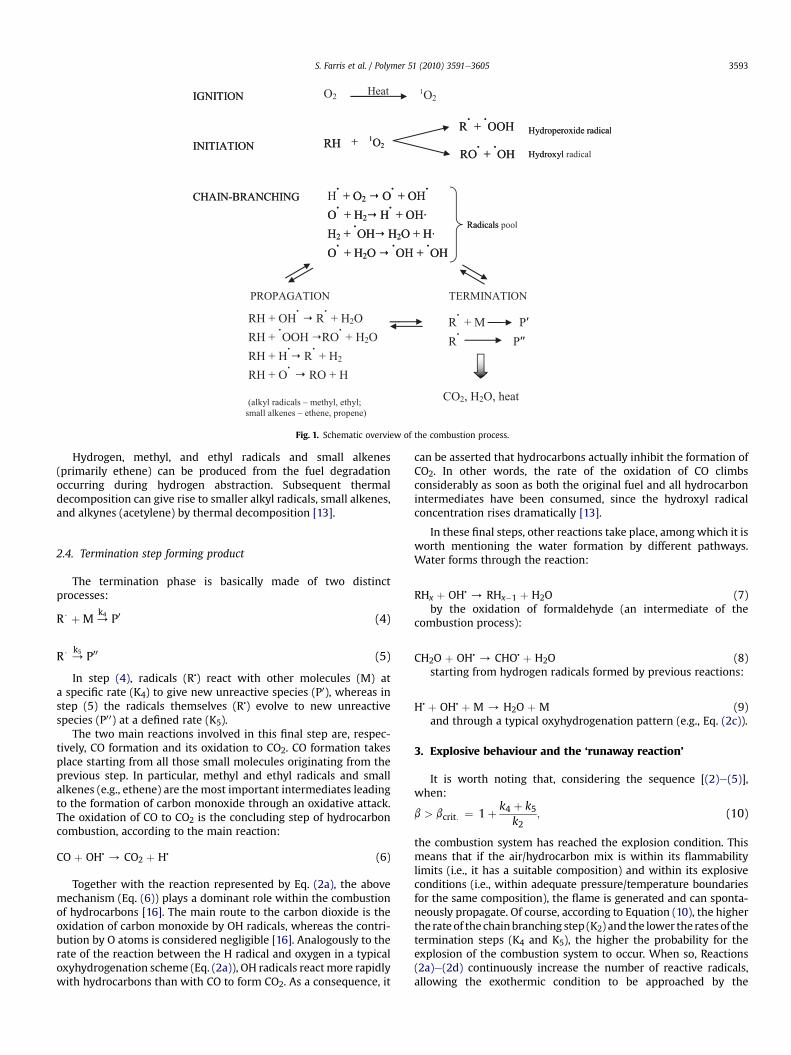
Fig. 1. Schematic overview of the combustion process.
S. Farris et al. / Polymer 51 (2010) 3591e3605 3593
Hydrogen, methyl, and ethyl radicals and small alkenes(primarily ethene) can be produced from the fuel degradationoccurring during hydrogen abstraction. Subsequent thermaldecomposition can give rise to smaller alkyl radicals, small alkenes,and alkynes (acetylene) by thermal decomposition [13].
2.4. Termination step forming product
The termination phase is basically made of two distinctprocesses:
R$ þM/k4 P0 (4)
R$ /k5 P00 (5)
In step (4), radicals (R�) react with other molecules (M) ata specific rate (K4) to give new unreactive species (P0), whereas instep (5) the radicals themselves (R�) evolve to new unreactivespecies (P00) at a defined rate (K5).
The two main reactions involved in this final step are, respec-tively, CO formation and its oxidation to CO2. CO formation takesplace starting from all those small molecules originating from theprevious step. In particular, methyl and ethyl radicals and smallalkenes (e.g., ethene) are the most important intermediates leadingto the formation of carbon monoxide through an oxidative attack.The oxidation of CO to CO2 is the concluding step of hydrocarboncombustion, according to the main reaction:
CO þ OH�/ CO2 þ H� (6)
Together with the reaction represented by Eq. (2a), the abovemechanism (Eq. (6)) plays a dominant role within the combustionof hydrocarbons [16]. The main route to the carbon dioxide is theoxidation of carbon monoxide by OH radicals, whereas the contri-bution by O atoms is considered negligible [16]. Analogously to therate of the reaction between the H radical and oxygen in a typicaloxyhydrogenation scheme (Eq. (2a)), OH radicals reactmore rapidlywith hydrocarbons than with CO to form CO2. As a consequence, it
can be asserted that hydrocarbons actually inhibit the formation ofCO2. In other words, the rate of the oxidation of CO climbsconsiderably as soon as both the original fuel and all hydrocarbonintermediates have been consumed, since the hydroxyl radicalconcentration rises dramatically [13].
In these final steps, other reactions take place, among which it isworth mentioning the water formation by different pathways.Water forms through the reaction:
RHx þ OH�/ RHx�1 þ H2O (7)
by the oxidation of formaldehyde (an intermediate of thecombustion process):
CH2O þ OH�/ CHO� þ H2O (8)
starting from hydrogen radicals formed by previous reactions:
H� þ OH� þ M / H2O þ M (9)and through a typical oxyhydrogenation pattern (e.g., Eq. (2c)).
3. Explosive behaviour and the ‘runaway reaction’
It is worth noting that, considering the sequence [(2)e(5)],when:
b > bcrit: ¼ 1þ k4 þ k5k2
; (10)
the combustion system has reached the explosion condition. Thismeans that if the air/hydrocarbon mix is within its flammabilitylimits (i.e., it has a suitable composition) and within its explosiveconditions (i.e., within adequate pressure/temperature boundariesfor the same composition), the flame is generated and can sponta-neously propagate. Of course, according to Equation (10), the higherthe rate of the chainbranching step (K2) and the lower the ratesof thetermination steps (K4 and K5), the higher the probability for theexplosion of the combustion system to occur. When so, Reactions(2a)e(2d) continuously increase the number of reactive radicals,allowing the exothermic condition to be approached by the
S. Farris et al. / Polymer 51 (2010) 3591e36053594
combustion system. Since the rate of the above-reported reactions(and thereby the rate of the heat released) increases exponentiallywith temperature (according to the Arrhenius law), the fuel/oxidantmixture becomes explosive. Therefore, Reactions (2a)e(2d) aregreatly important in the oxidation reaction mechanism of anyhydrocarbon because they allow the propagation of the flame. Thisexothermic reaction is also called the ‘runaway reaction’, whichoccurs when the reaction rate increases because of an increase intemperature, causing a further increase in temperature and a furtherincrease in the reaction rate. Since direct combustion byatmosphericoxygen in aflame is a reactionmediatedby radical intermediates, theconditions for radical production are guaranteed by thermalrunaway, where the heat generated by combustion is necessary tomaintain the high temperature for radical production. The ‘runawayreaction’ is, therefore, the key condition for radical production.
4. Laminar flame profile
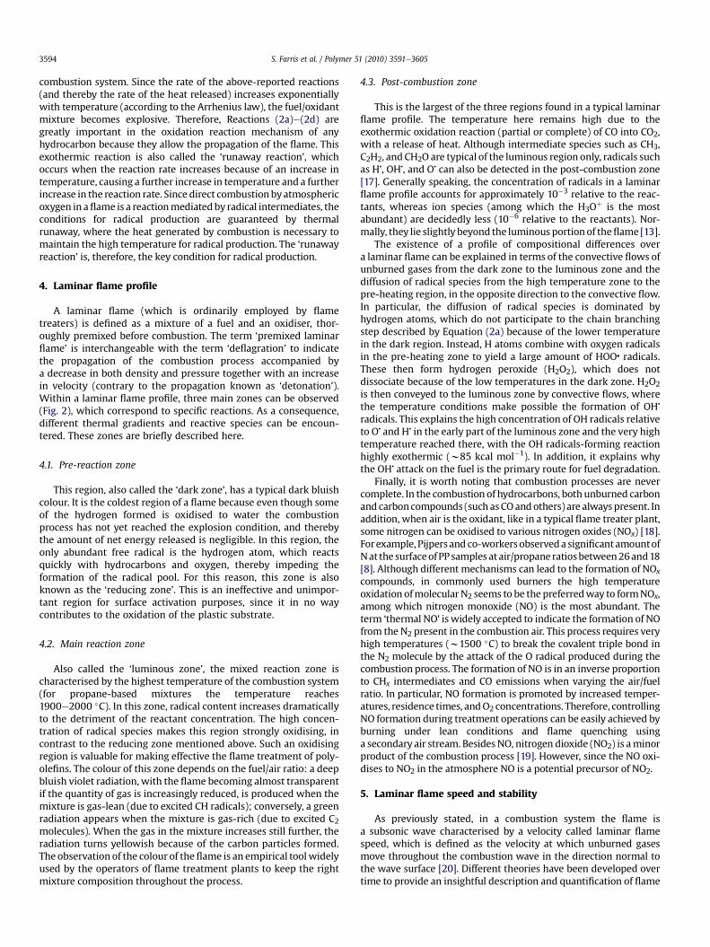
A laminar flame (which is ordinarily employed by flametreaters) is defined as a mixture of a fuel and an oxidiser, thor-oughly premixed before combustion. The term ‘premixed laminarflame’ is interchangeable with the term ‘deflagration’ to indicatethe propagation of the combustion process accompanied bya decrease in both density and pressure together with an increasein velocity (contrary to the propagation known as ‘detonation’).Within a laminar flame profile, three main zones can be observed(Fig. 2), which correspond to specific reactions. As a consequence,different thermal gradients and reactive species can be encoun-tered. These zones are briefly described here.
4.1. Pre-reaction zone
This region, also called the ‘dark zone’, has a typical dark bluishcolour. It is the coldest region of a flame because even though someof the hydrogen formed is oxidised to water the combustionprocess has not yet reached the explosion condition, and therebythe amount of net energy released is negligible. In this region, theonly abundant free radical is the hydrogen atom, which reactsquickly with hydrocarbons and oxygen, thereby impeding theformation of the radical pool. For this reason, this zone is alsoknown as the ‘reducing zone’. This is an ineffective and unimpor-tant region for surface activation purposes, since it in no waycontributes to the oxidation of the plastic substrate.
4.2. Main reaction zone
Also called the ‘luminous zone’, the mixed reaction zone ischaracterised by the highest temperature of the combustion system(for propane-based mixtures the temperature reaches1900e2000 �C). In this zone, radical content increases dramaticallyto the detriment of the reactant concentration. The high concen-tration of radical species makes this region strongly oxidising, incontrast to the reducing zone mentioned above. Such an oxidisingregion is valuable for making effective the flame treatment of poly-olefins. The colour of this zone depends on the fuel/air ratio: a deepbluish violet radiation, with the flame becoming almost transparentif the quantity of gas is increasingly reduced, is produced when themixture is gas-lean (due to excited CH radicals); conversely, a greenradiation appears when the mixture is gas-rich (due to excited C2molecules). When the gas in the mixture increases still further, theradiation turns yellowish because of the carbon particles formed.The observation of the colour of theflame is an empirical toolwidelyused by the operators of flame treatment plants to keep the rightmixture composition throughout the process.
4.3. Post-combustion zone
This is the largest of the three regions found in a typical laminarflame profile. The temperature here remains high due to theexothermic oxidation reaction (partial or complete) of CO into CO2,with a release of heat. Although intermediate species such as CH3,C2H2, and CH2O are typical of the luminous region only, radicals suchas H�, OH�, and O� can also be detected in the post-combustion zone[17]. Generally speaking, the concentration of radicals in a laminarflame profile accounts for approximately 10�3 relative to the reac-tants, whereas ion species (among which the H3Oþ is the mostabundant) are decidedly less (10�6 relative to the reactants). Nor-mally, they lie slightly beyond the luminous portionof theflame [13].
The existence of a profile of compositional differences overa laminar flame can be explained in terms of the convective flows ofunburned gases from the dark zone to the luminous zone and thediffusion of radical species from the high temperature zone to thepre-heating region, in the opposite direction to the convective flow.In particular, the diffusion of radical species is dominated byhydrogen atoms, which do not participate to the chain branchingstep described by Equation (2a) because of the lower temperaturein the dark region. Instead, H atoms combine with oxygen radicalsin the pre-heating zone to yield a large amount of HOO� radicals.These then form hydrogen peroxide (H2O2), which does notdissociate because of the low temperatures in the dark zone. H2O2
is then conveyed to the luminous zone by convective flows, wherethe temperature conditions make possible the formation of OH�
radicals. This explains the high concentration of OH radicals relativeto O� and H� in the early part of the luminous zone and the very hightemperature reached there, with the OH radicals-forming reactionhighly exothermic (w85 kcal mol�1). In addition, it explains whythe OH� attack on the fuel is the primary route for fuel degradation.
Finally, it is worth noting that combustion processes are nevercomplete. In the combustion of hydrocarbons, bothunburned carbonand carboncompounds (such asCOandothers) are alwayspresent. Inaddition, when air is the oxidant, like in a typical flame treater plant,some nitrogen can be oxidised to various nitrogen oxides (NOx) [18].Forexample, Pijpersand co-workersobserveda significant amountofNat the surfaceofPPsamples at air/propane ratiosbetween26and18[8]. Although different mechanisms can lead to the formation of NOx
compounds, in commonly used burners the high temperatureoxidation ofmolecular N2 seems to be the preferredway to formNOx,among which nitrogen monoxide (NO) is the most abundant. Theterm ‘thermal NO’ is widely accepted to indicate the formation of NOfrom the N2 present in the combustion air. This process requires veryhigh temperatures (w1500 �C) to break the covalent triple bond inthe N2 molecule by the attack of the O radical produced during thecombustion process. The formation of NO is in an inverse proportionto CHx intermediates and CO emissions when varying the air/fuelratio. In particular, NO formation is promoted by increased temper-atures, residence times, andO2 concentrations. Therefore, controllingNO formation during treatment operations can be easily achieved byburning under lean conditions and flame quenching usinga secondary air stream. BesidesNO, nitrogen dioxide (NO2) is aminorproduct of the combustion process [19]. However, since the NO oxi-dises to NO2 in the atmosphere NO is a potential precursor of NO2.
5. Laminar flame speed and stability
As previously stated, in a combustion system the flame isa subsonic wave characterised by a velocity called laminar flamespeed, which is defined as the velocity at which unburned gasesmove throughout the combustion wave in the direction normal tothe wave surface [20]. Different theories have been developed overtime to provide an insightful description and quantification of flame
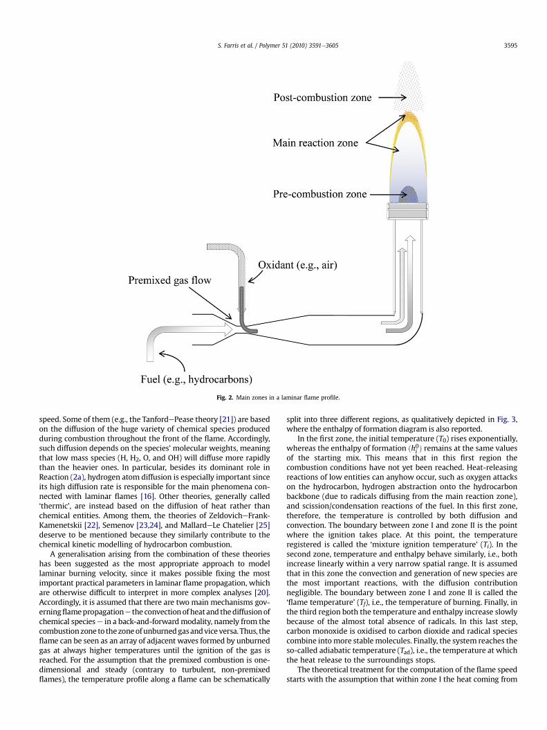
Fig. 2. Main zones in a laminar flame profile.
S. Farris et al. / Polymer 51 (2010) 3591e3605 3595
speed. Some of them (e.g., the TanfordePease theory [21]) are basedon the diffusion of the huge variety of chemical species producedduring combustion throughout the front of the flame. Accordingly,such diffusion depends on the species’ molecular weights, meaningthat low mass species (H, H2, O, and OH) will diffuse more rapidlythan the heavier ones. In particular, besides its dominant role inReaction (2a), hydrogen atom diffusion is especially important sinceits high diffusion rate is responsible for the main phenomena con-nected with laminar flames [16]. Other theories, generally called‘thermic’, are instead based on the diffusion of heat rather thanchemical entities. Among them, the theories of ZeldovicheFrank-Kamenetskii [22], Semenov [23,24], and MallardeLe Chatelier [25]deserve to be mentioned because they similarly contribute to thechemical kinetic modelling of hydrocarbon combustion.
A generalisation arising from the combination of these theorieshas been suggested as the most appropriate approach to modellaminar burning velocity, since it makes possible fixing the mostimportant practical parameters in laminar flame propagation, whichare otherwise difficult to interpret in more complex analyses [20].Accordingly, it is assumed that there are two main mechanisms gov-erningflamepropagatione the convectionofheatand thediffusionofchemical speciese in a back-and-forwardmodality, namely from thecombustionzone to thezoneofunburnedgasandviceversa. Thus, theflame can be seen as an array of adjacent waves formed by unburnedgas at always higher temperatures until the ignition of the gas isreached. For the assumption that the premixed combustion is one-dimensional and steady (contrary to turbulent, non-premixedflames), the temperature profile along a flame can be schematically
split into three different regions, as qualitatively depicted in Fig. 3,where the enthalpy of formation diagram is also reported.
In the first zone, the initial temperature (T0) rises exponentially,whereas the enthalpy of formation ðh0i Þ remains at the same valuesof the starting mix. This means that in this first region thecombustion conditions have not yet been reached. Heat-releasingreactions of low entities can anyhow occur, such as oxygen attackson the hydrocarbon, hydrogen abstraction onto the hydrocarbonbackbone (due to radicals diffusing from the main reaction zone),and scission/condensation reactions of the fuel. In this first zone,therefore, the temperature is controlled by both diffusion andconvection. The boundary between zone I and zone II is the pointwhere the ignition takes place. At this point, the temperatureregistered is called the ‘mixture ignition temperature’ (Ti). In thesecond zone, temperature and enthalpy behave similarly, i.e., bothincrease linearly within a very narrow spatial range. It is assumedthat in this zone the convection and generation of new species arethe most important reactions, with the diffusion contributionnegligible. The boundary between zone I and zone II is called the‘flame temperature’ (Tf), i.e., the temperature of burning. Finally, inthe third region both the temperature and enthalpy increase slowlybecause of the almost total absence of radicals. In this last step,carbon monoxide is oxidised to carbon dioxide and radical speciescombine intomore stablemolecules. Finally, the system reaches theso-called adiabatic temperature (Tad), i.e., the temperature at whichthe heat release to the surroundings stops.
The theoretical treatment for the computation of the flame speedstarts with the assumption that within zone I the heat coming from

Distance (mm)
Ti
Tf
Tad
meT
p erutare
0 1 2 3 4 5 6 7
ZONE I ZONE II ZONE III
h0i
Fig. 3. Spatial evolution of temperature and enthalpy of formation in a premixedlaminar flame.
S. Farris et al. / Polymer 51 (2010) 3591e36053596
zone II by convection equals the heat required to raise the tempera-ture of the unburned gases to the ignition temperature (Ti). Secondly,it is assumed that the increase in temperature between adjacent gaslayers is constant. In other words, this means that the slope of thetemperature curve is linear, and thereby can be approximated by theexpression [(Tf e Ti)/d], where d is the thickness of the reaction zone.From the enthalpy balance the following equation can be obtained:
mcp ¼ l
�Tf � Ti
�d
A (11)
where l is the thermal conductivity, m is the mass rate of theunburned gasmixture into the combustionwave, and A is the cross-sectional area assumed as unity [20]. According to the one-dimen-sional feature of the problem, the mass ratem can be expressed as:
m ¼ rAu ¼ rASL; (12)
where r is the unburned gas density, u is the velocity of theunburned gases, and SL is the symbol for laminar flame velocity. Asunburned gases enter normal to the wave, by definition it can bewritten SL ¼ u. Therefore, Equation (11) becomes:
rSLcpðTi � T0Þ ¼ l�Tf � Ti
�.d (13)
Thus the equation for the computation of the flame speed can beeasily inferred:
SL ¼ l
rcp
�Tf � TiTi � T0
�1d
(14)
where cp is the specific heat capacity of the fuel. From Equation (14)it is possible to observe the direct relationship between flamespeed (SL) and flame temperature (Tf), i.e., the higher the flamespeed, the higher the flame temperature. It allows us to talk aboutflame temperature and flame speed interchangeably. Unfortu-nately, in the above equation, the term d (the reaction zone thick-ness) is unknown; nevertheless, it can be related to flame speed bythe following expression:
ru ¼ rSL ¼ ud; (15)
which assumes the total mass per unit area entering the reactionzone is equal to the mass consumed in that zone for the steady flowproblem being considered. In Equation (15), u is the reaction rate interms of concentration (g cm�3) per unit time. Equation (14) can,therefore, be rewritten as:
SL ¼�l
rcp
�Tf � TiTi � T0
�u
r
�1=2w
�au
r
�1=2(16)
where r is the unburned gas density and a is the thermal diffusivity.More specifically:
a�m2s�1
�¼ l
rcp
�W m�1 K�1
��kg m�3
�J kg�1 K�1
� (17)
The denominator in Equation (17) is known as the volumetricheat capacity (J m�3 K�1). Thermal diffusivity can ultimately bedefined as the ratio of thermal conductivity to volumetric heatcapacity. In practice, thermal diffusivity is ameasure of the ability ofa given substance (or a mixture, as in the case of a flame) to rapidlyadjust its temperature to that of the surroundings. Since themass ofreacting fuel mixture consumed by the laminar flame is given by:
rSLw�l
cpu
�1=2
(18)
combining Equations (15) and (18) yields the following expression:
dwa
SL(19)
From Equation (19) the average thickness of the luminous zonefor a laminar flame can easily be drawn. Since, for hydrocarbonflames, the value of a (at a mean temperature of 1300 K) and SL canrealistically be approximated to 5 cm2 s�1 and 35e40 cm s�1,respectively, d assumes values close to 1.0e1.5 mm. As will bediscussed later, this aspect has a valuable practical consequence tofully exploiting the benefit of a flame treatment during the surfaceactivation of polyolefin substrates. Equation (19) also highlights theinverse proportion between the thickness of the luminous zone andflame speed. Thus, flame speed (i.e., flame temperature) shouldalways be adjusted to a certain value of d to treat the samples ina feasible fashion. This can also be achieved by setting the value ofthermal diffusivity a, since increasing thermal diffusivity leads toan increase in flame speed, as inferred from Equation (16). There-fore, for high values of a the quality of the combustion system willbe enhanced due to an increase in flame temperature, whichcorresponds to an increase in flame treatment yield. An adequatevalue of a can be achieved by reducing the volumetric heat capacityof themixture (i.e., the denominator of Equation (17)), which can beobtained by decreasing the specific heat capacity of the fuel (cp). Todo so, common practice is to replace nitrogen in the fuel mixturewith other lower cp diluents such as argon or helium. It has beenreported that when helium is added to a stoichiometric methane/air mixture, the flame speed is roughly threefold higher than usingnitrogen (w125 cm s�1 vs. w40 cm s�1) [26e28].
Another aspect that should be pointed out is the effect ofpressure on the flame speed of a stoichiometric air/gasmixture. Thepressure dependence of flame speed is described by the followingequation [20]:
SLw�pðn�2Þ
�1=2(20)
where n is the overall order of the reaction. Therefore, for a givensecond order reaction, flame speed seems to be independent of

S. Farris et al. / Polymer 51 (2010) 3591e3605 3597
pressure. However, by contrast, hydrocarbon/air reactions arerarely second order. Indeed, experimental data collected by severalinvestigators suggest that the order of a general combustionprocess mostly falls around 1.75 [29]. This is why a reduction inflame speed is encountered with increasing pressure. A deepercomprehension of this phenomenon can be achieved by looking atthe most important oxyhydrogenation reaction governing theformation of the radical pool, i.e.: refer reaction (2a)
Any reaction that inhibits the formation of H atoms or competeswith the above mechanism will hinder the oxidation process, andthereby the combustion rate. For instance, the reaction:
H� þ O2 þ M /�OOH þ M (21)
clearly competes with Reaction (2a). Moreover, since it is a thirdorder reaction, it is much more pressure-dependent than Reaction(2a). The ultimate relevant consequence is that when increasingpressure, Reaction (21) tends to slow down the overall combustionprocess and, thus, flame speed. Results from analytical calculationsof flame speeds under different temperature/pressure conditionswith detailed kinetic aspects can be found in the literature [30e33].Moreover, it has to be mentioned that the decrease in SL withincreasing pressure becomes more pronounced for pressures aboveatmospheric conditions (1e5 atm). This is because, contrary towhat happens at high pressures, below 1 atm Reaction (21) doesnot compete with Reaction (2a), and any decrease owing to Reac-tion (21) is balanced by a rise in temperature due to chainbranching step reactions such as (2a).
At the end of this section, afinal remark deserves to be stressed asfar as laminar flame propagation is concerned. It is nowadaysaccepted that although diffusion phenomena dominate in initiallyunmixed fuel/oxidiser systems, reaction rate mechanisms prevail inpremixed homogeneous mixtures. It is worth emphasising thatflame propagation is mostly because of the diffusion of heat andmass, i.e., it is made possible by a diffusion mechanism predomi-nantly. The roleof the reaction rate is instead intimately related to thethermal profile of the laminarflame, since it governs the thickness ofthe reaction zone and temperature gradient. In other words,although the strong effect of the temperature is undisputable, flamepropagationhas tobeprimarilyattributed to thediffusionofheat andmass. It is definitively expressed by the following expression:
SLwðaRRÞ1=2 (22)
This states that the propagation rate is proportional to thesquare root of the diffusivity and the reaction rate [20].
6. Flame treatment of polyolefins
The term polyolefin encompasses all those polymers producedby an olefin as a startingmonomer, whose general formula is CnH2n.Most common polyolefins in the packaging field are polyethylene(PE) and PP. Although they have different specific properties, it isrecognised that both polymers are inherently hydrophobic, whichis in turn responsible for their typical poor wettability, especially towaterborne systems. For this reason, polyolefins generally need tobe surface-activated before the deposition of inks, paints, adhe-sives, metals, and coatings. Flame treatment is a valuable techniqueto improve the surface energy of polyolefins, although it has beenexploited to a minor extent with respect to corona treatment so far.However, because of improvements in safety conditions as well asin some technical aspects, it is receiving renewed attention, espe-cially by those sectors (e.g., packaging) that historically laggedbehind in the exploitation of the technique.
It has been reported that the surface activation of polyolefins byflame treatment is based on the free radical degradation
mechanism, which occurs at the tertiary carbon of the PP chain andaccording to a random attack in the case of PE [34]. Two main stepsare involved in the oxidation process of PP: 1) the breakage of theCeH links along the polymer surface by the high temperaturegenerated by the combustion process (w1700e1900 �C); and 2) theinsertion of oxygen-based groups corresponding with the brokenlinks, leading to newly available hydrophilic sites for the interactionbetween coating and substrate. In particular, the oxidation ofmethyl groups (eCH3) into eCH2OH groups following treatmenthas been judged the most relevant surface chemistry changeaffecting both the wettability and adhesion properties of polyolefinsubstrates [35]. The generally accepted scheme is reported below:
RH/R$þH (23)
R$ þ O2/ROO$/ROOH/oxidised products (24)
It seems that the oxidation process is principally mediated bythe OH� radicals in the flame. To elucidate the chemical changesonto the polyolefins’ surface following flame treatment, severaltechniques have been used. In particular, X-ray photoelectronspectroscopy, also called ESCA (electron spectroscopy for chemicalanalysis), and static secondary ion mass spectroscopy (SSIMS) haveconfirmed an increased level of oxidation, as demonstrated by newfunctionalities formed on the polyolefins’ surface, such as hydroxyl,carbonyl, and carboxyl groups [35e37]. However, it has beenascertained that, working conditions being equal, more oxygen isincorporated onto PE films than PP films after flame treatment. Inaddition, it has been proven that the majority of the oxygen addedto PP by the flame is in the form of hydroxyl species, which accountfor approximately 20e30% [38]. Nitrogen fixation has also beendetected as a consequence of treatment, although it seems to occuron PE samples rather than PP. Nevertheless, the fixation of nitrogenis quantitatively less important than oxygen fixation, as revealed byESCA measurements (N/C atomic ratios < 0.03; O/C atomicratios > 0.1e0.2) [39]. The mechanism responsible for the modifi-cation of the PP surface caused by the hydrocarbon flame has beenbrilliantly elucidated by Strobel and co-workers [13]. Arising fromtheir work, it seems that the polymer radical formation occursprimarily by hydrogen abstraction because of the free radicals inthe flame, such as O atoms, H atoms, and OH radicals, according tothe reactions (3a) and (3c) and following reaction [25]:
RHþ O/R$ þ OH (25)
where R� is an alkyl radical. Not only can the radical species in theflame provoke polymer radical formation, but also so can thethermal effect according to the mechanism:
RH/R$ þ H (26)
Based on the results obtained using a combustion mode [40],and considering that the reactivity of the H atom for hydrogenabstraction is three to five orders of magnitude inferior than thereactivity of O and OH [41], the authors concluded that, at a specificequivalence ratio of 0.93, OH radicals, O atoms, and heat are thedriving forces for polymer radical formation. Most alkyl radicalsformed during the previous steps (Eqs. (25) and (26)) react withoxygen atoms, generating polymer alkoxy radicals [42]:
R$ þ O/RO$ (27)
It iswell established as suchpolymer alkoxy radicals (RO�) are themain species involved in the chain backbone scission of PP duringoxidation through the well-known b-scission reaction (Fig. 4).
Surface oxidation can also take place by additional routes;however, these tend to be less important than the aforementioned

S. Farris et al. / Polymer 51 (2010) 3591e36053598
direct reactionwithatomicoxygen. Forexample, the alkyl radicals (R�)can be attacked by molecular oxygen (O2), yielding peroxy polymerradicals (ROO�), which in turn can abstract hydrogen from otherpolymer chains to produce polymer hydroxyperoxides (ROOH). All ofthese intermediates (alkoxy, peroxy, and hydroperoxy) can originatea large variety of oxidised species reacting with atomic oxygen, OHradicals, or even through cross-reactionwith intramolecular polymerradicals [41]. Arising from these different reaction mechanisms,a wide range of new chemical groups can be inserted onto the poly-olefin backbone. In particular, the formation of hydroxyl, carboxyl,and carbonyl groups is the most relevant concerning the increase inthe wettability ad adhesion properties.
Finally, it isworth stressing the heterogeneity of oxidation on thepolyolefin surface. This has been attributed to the different physicaldomains in a typical semi-crystalline polymer such as PP. Morespecifically, it seems that the regions most susceptible to treatmentare those amorphous rather than crystalline. This fact would justifythe scarce homogeneity in the extent of the oxidation, which is thebasis of the hysteresis phenomenon that can be observed duringcontact angle measurements on flame-treated PP films.
7. Flame treatment equipment
Although conceptually similar, flame treaters used in packagingindustries for polyolefin surfaces show obvious differencesdepending on whether the sample to be treated has a two-dimensional or three-dimensional geometry. In both cases, threemain components can be recognised. For 3D objects, the planttypically consists of (Fig. 5a):
(1) a conveyor belt, which allows a continuous loop ofmaterial, i.e.,the polyolefin objects, which are normally mounted on heat-resistant holders;
(2) a cleaning device, such as a stream of compressed air ora brush-like system. This is normally placed a few centimetresin front of the burners to assure the removal of all smallparticles (e.g., dust) that might negatively affect successfulflame treatment; and
(3) a burner, i.e., the basic part of the equipment that produces theoxidising flame.
A typical plant for the flame treatment of polyolefin flexiblefilms (Fig. 5b) is instead conceived as follows:
(1) a burner, which should produce a suitable flame for treatingthe surface of the web;
(2) a treater roll, which is normally water-cooled. This enables therewinding of the treated film and prevents any unwanteddamage due to overheating; and
Fig. 4. Schematic representation of a b-scission reaction on a polyolefin backbone.
(3) a nip roll, which is usually rubber-coated. Its function is to exerta certain pressure on the film to ensure the necessary contactbetween the web and the cooled roll. This prevents the forma-tion of bubbles and/or blisters, which might otherwise impedethe right thermal exchangebetween theweband the treater roll.
Certainly, the core of a typical flaming system is the burner.Nowadays, burners are complex parts affecting strongly theoutcome of the whole process. Despite the wide range of burnersavailable on the market, a common feature is the system thatdelivers the gas/air mixture to the burner nozzle (head) by exploit-ing the still valid principles developed by Venturi and Bunsen. Sucha system, generally known as Venturi mixer, is located a fewmetresupstream of the burner. Burners fall into two main groups. Atmo-spheric burners are so called because part of the air used to generatethe premixed fuel/air laminar flame is from the surrounding atmo-sphere, and is thereby at atmospheric pressure. This is because thegas entering the orifice at the base of the mixing tube is at lowpressure (only a few inches of water column), providing onlyapproximately 50% of the required air for the combustion. Conse-quently, the remainder is drawn from the environment around thenozzle, where the free air is usually conveyed by openings near theburner. An example of atmospheric air is the Bunsen burner.Contrary to atmospheric burners, power burners provide a powerful
Fig. 5. Schematic representation of a flame treatment station for polyolefin a) tridi-mensional objects and b) flexible films.

S. Farris et al. / Polymer 51 (2010) 3591e3605 3599
source of combustion air, making it possible to achieve higherenergy output compared with atmospheric burners.
In an attempt to fulfil market requirements, different burnershave been designed and developed over time, and a large variety ofconfigurations are currently available. Gun-type nozzles wereespecially developed for the flame treatment of three-dimensionalobjects, where part of the gas/air mixture is deviated into smallholes at a speed that is gradually reduced until continuous ignitionis provided to themain gas/air flux coming out of the central orifice.This makes it possible to increase the velocity of the laminar flameout of the head of the burner, thereby achieving the targeted heatoutput. The burners used for flaming flexible films, e.g., polyolefinsfor the packaging industry, are based on a similar principle. In thiscase, the need to spread the flame on awider front (i.e., equal to thewidth of the roll) led to developing pipe-like nozzles with a longarray of drilled holes emitting the flame. On each side of this mainrow of drilled holes are smaller orifices, above which deflectorscontrol the speed of the flame. So-called ribbon burners representthe last generation of burners available on the market. They consistof a regular shaped slot mounted with a dimpled geometry ribbonstack. Such a design can reduce the speed of part of the gas/airmixturewithout needing devices such as deflectors or ignition rails.To date, the ribbon burner is themost widely adopted solution at anindustrial level because it can attain customised flame patterns byadjusting the width of the slot and configuring the ribbons [11].
erutarepmet e
malF
φ < 1fuel-lean
φ > 1fuel-rich
1.0
Fig. 6. Flame temperature trend as a function of the equivalence ratio (f).
8. Flame treatment variables
8.1. Process variables
8.1.1. Gas/air ratioThe molar ratio of the fuel to the oxidiser is probably the most
important parameter within the flame treatment process. For thisreason, particular care must be paid to setting it adequately beforetheflame treatment is started. Foreachgas thereexists a specific andwell-defined amount of oxidiser at which the fuel is completelyburnt. This precise ratio is known as the stoichiometric ratio, whichrelies on the chemical structure of the gas. For example, the stoi-chiometric ratio methane/air bymass is equal to 1:17.2, whereas fora propane/air flame it is 1:15.5, i.e., 15.5 kg of air is needed for thecomplete combustion of 1 kg of propane. However, in practicalapplications it is unlikely that the stoichiometric ratio can be veri-fied. Most probably, the flame obtained will be below or above thisvalue. Therefore, the concept of the equivalence ratio (f), defined asthe actual mass gas/air ratio used during treatment divided thestoichiometric fuel-to-oxidiser ratio [43], is widely accepted:
f ¼ mfuel=moxidizer�mfuel=moxidizer
�stoichiometric
(28)
wherem is the mass. The most common parameter is the reciprocalof the equivalence ratio, which is called the lambda factor and isexpressed by the formula:
l ¼ f�1 (29)
As a consequence, fuel-lean (oxidising) flames will have f < 1and fuel-rich flames f > 1 (vice versa as far as the l factor is con-cerned). Unambiguously, both l and f will be equal to the unit atthe stoichiometric ratio. It is worth pointing out that, for a givencombustion system, the maximum yield (expressed in terms offlame temperature) is achieved at the stoichiometric ratio, whereneither excess fuel nor excess oxidiser can be verified. Conversely,as f veers from the stoichiometric value (below and above), theflame temperature drops correspondingly (Fig. 6).
This is because although excess fuel (or oxidiser flame) couldnever participate chemically in the combustion reaction, it doesaffect the system from a physical point of view since, depending onits specific heat value, such an excess tends to draw heat from thecombustion system, thereby causing the aforementioned decreasein yield. In practice, themost widely adopted configuration foreseesa fuel/air ratio slightly shifted to an oxidising flame composition (i.e., fuel-lean), because, as mentioned previously, the web surfaceactivation strictly depends on both flame temperature and oxygenradical concentration. Thus, the best working condition can oftenbe a compromise between high flame temperature and oxygenradical content in the flame. It has been proven by many authorsthat oxidising flames (0.75 < f < 1) lead to the best surface acti-vation of polyolefin substrates [37,38,44,45]. More recently,a detailed report by Strobel and co-workers [13] suggested the bestperforming equivalence ratio was 0.93 for all combinations offlame-to-film distance, flame power, and film speed usinga methane/air mixture. At this optimum value, a maximum surfaceenergy of approximately 62mJm�2 (according to the ASTMwettingtest standard method [46]) was achieved. Accordingly, the highestESCA O/C atomic ratio of flame-treated PP was recorded forequivalence ratio values ranging between 0.92 and 0.94, therebyfollowing the same trend as the wettability measures. The authorsconcluded that such a high level of oxidation is the main reason forthe increased wettability of the flame-treated PP surface.
8.1.2. Mixture flowBased on the previous discussion, it is necessary to expose the
polyolefin surface to a certain amount of thermal energy (heat) toachieve the desired activation of the web surface. Defining thisquantity is not an easy task because the thermal energy requiredduring the flaming process strongly relies on other parameters.Among them, it is worth mentioning flame power (i.e., the productof the volume of fuel burned per unit time and the heat content ofthe fuel, expressed inW), the exposure time of the film to the flame,the configuration of the burner, and the gap between the flame andfilm surface. However, a practical way to control the energysupplied to the web is to adjust the mixture flow (m3 h�1).Increasing themixture flow leads to a corresponding increase in thetreatment efficacy to a certain level (Fig. 7, Q1). Any mixture flowsetting beyond this boundary value (Fig. 7, Q2) is profitless andcauses unnecessary energy waste and thermal stress on the plasticfilm. Based on these principles, it has been possible to set down therelationship between mixture flow and flame treatment efficacy interms of the surface energy of the treated surface.
In Fig. 8, the results obtained by our team for bi-oriented poly-propylene (BOPP) at low and high line speeds are reported (per unit
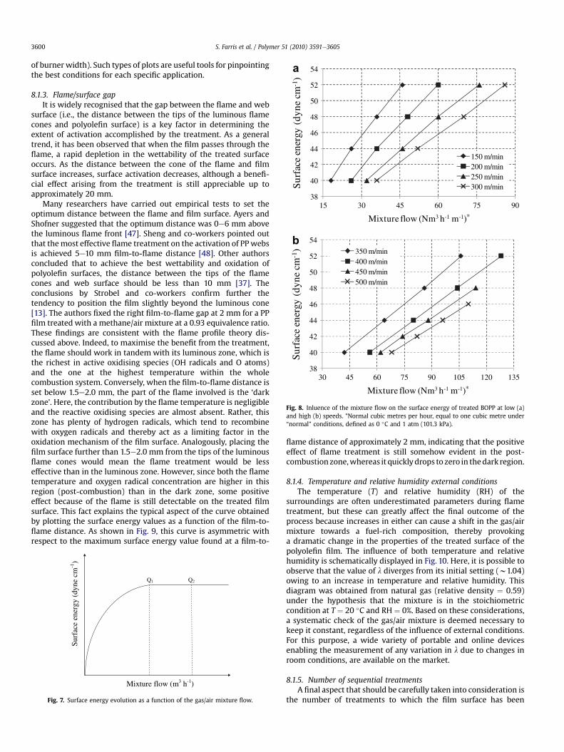
38
40
42
44
46
48
50
52
54
15 30 45 60 75 90
mcenyd(
ygreneecafru
S1-)
Mixture flow (Nm3 h-1 m-1)*
a
150 m/min200 m/min250 m/min300 m/min
38
40
42
44
46
48
50
52
54
30 45 60 75 90 105 120 135
mcenyd(
ygreneecafru
S1-)
Mixture flow (Nm3 h-1 m-1)*
b
350 m/min400 m/min450 m/min500 m/min
Fig. 8. Inluence of the mixture flow on the surface energy of treated BOPP at low (a)and high (b) speeds. *Normal cubic metres per hour, equal to one cubic metre under“normal” conditions, defined as 0 �C and 1 atm (101.3 kPa).
S. Farris et al. / Polymer 51 (2010) 3591e36053600
of burner width). Such types of plots are useful tools for pinpointingthe best conditions for each specific application.
8.1.3. Flame/surface gapIt is widely recognised that the gap between the flame and web
surface (i.e., the distance between the tips of the luminous flamecones and polyolefin surface) is a key factor in determining theextent of activation accomplished by the treatment. As a generaltrend, it has been observed that when the film passes through theflame, a rapid depletion in the wettability of the treated surfaceoccurs. As the distance between the cone of the flame and filmsurface increases, surface activation decreases, although a benefi-cial effect arising from the treatment is still appreciable up toapproximately 20 mm.
Many researchers have carried out empirical tests to set theoptimum distance between the flame and film surface. Ayers andShofner suggested that the optimum distance was 0e6 mm abovethe luminous flame front [47]. Sheng and co-workers pointed outthat themost effective flame treatment on the activation of PPwebsis achieved 5e10 mm film-to-flame distance [48]. Other authorsconcluded that to achieve the best wettability and oxidation ofpolyolefin surfaces, the distance between the tips of the flamecones and web surface should be less than 10 mm [37]. Theconclusions by Strobel and co-workers confirm further thetendency to position the film slightly beyond the luminous cone[13]. The authors fixed the right film-to-flame gap at 2 mm for a PPfilm treated with a methane/air mixture at a 0.93 equivalence ratio.These findings are consistent with the flame profile theory dis-cussed above. Indeed, to maximise the benefit from the treatment,the flame should work in tandem with its luminous zone, which isthe richest in active oxidising species (OH radicals and O atoms)and the one at the highest temperature within the wholecombustion system. Conversely, when the film-to-flame distance isset below 1.5e2.0 mm, the part of the flame involved is the ‘darkzone’. Here, the contribution by the flame temperature is negligibleand the reactive oxidising species are almost absent. Rather, thiszone has plenty of hydrogen radicals, which tend to recombinewith oxygen radicals and thereby act as a limiting factor in theoxidation mechanism of the film surface. Analogously, placing thefilm surface further than 1.5e2.0 mm from the tips of the luminousflame cones would mean the flame treatment would be lesseffective than in the luminous zone. However, since both the flametemperature and oxygen radical concentration are higher in thisregion (post-combustion) than in the dark zone, some positiveeffect because of the flame is still detectable on the treated filmsurface. This fact explains the typical aspect of the curve obtainedby plotting the surface energy values as a function of the film-to-flame distance. As shown in Fig. 9, this curve is asymmetric withrespect to the maximum surface energy value found at a film-to-
mc enyd( ygrene ecafruS
1-)
Mixture flow (m3 h-1)
Q1 Q2
Fig. 7. Surface energy evolution as a function of the gas/air mixture flow.
flame distance of approximately 2 mm, indicating that the positiveeffect of flame treatment is still somehow evident in the post-combustionzone,whereas it quicklydrops to zero in thedark region.
8.1.4. Temperature and relative humidity external conditionsThe temperature (T) and relative humidity (RH) of the
surroundings are often underestimated parameters during flametreatment, but these can greatly affect the final outcome of theprocess because increases in either can cause a shift in the gas/airmixture towards a fuel-rich composition, thereby provokinga dramatic change in the properties of the treated surface of thepolyolefin film. The influence of both temperature and relativehumidity is schematically displayed in Fig. 10. Here, it is possible toobserve that the value of l diverges from its initial setting (w1.04)owing to an increase in temperature and relative humidity. Thisdiagram was obtained from natural gas (relative density ¼ 0.59)under the hypothesis that the mixture is in the stoichiometriccondition at T ¼ 20 �C and RH ¼ 0%. Based on these considerations,a systematic check of the gas/air mixture is deemed necessary tokeep it constant, regardless of the influence of external conditions.For this purpose, a wide variety of portable and online devicesenabling the measurement of any variation in l due to changes inroom conditions, are available on the market.
8.1.5. Number of sequential treatmentsA final aspect that should be carefully taken into consideration is
the number of treatments to which the film surface has been

0,40
0,50
0,60
0,70
0,80
0,90
1,00
0 20 40 60 80 100
λeulav
Temperature (°C)
RH = 0%RH = 25%RH = 50%RH = 75%RH = 100%
1.00
0.90
0.80
0.70
0.60
0.50
0.40
Fig. 10. Influence of room conditions (temperature and relative humidity) on the l
value of a stoichiometric (T ¼ 20 �C; RH ¼ 0%) natural gas (dr ¼ 0.59)/air mixture.
S. Farris et al. / Polymer 51 (2010) 3591e3605 3601
submitted. Although it strongly depends on other aspects (i.e.,flame temperature, flame flow, flame-to-film distance), somegeneral considerations can help carry out the appropriate treat-ment. Contrary to what common sense might suggest, increasingthe number of treatments in the same sample does not implya proportional increase in the surface properties of the polyolefinsurface. Indeed, in particular when high temperatures are reached,over treatment lead to surface reorganisation in the modifiedpolymer surface. Two different phenomena have been highlightedin this respect [8]. On one hand, as a result of over treatment, theoxygen-containing functional groups inserted in the first step oftreatment can disappear from the surface. On the other hand, hightemperatures can trigger the migration of the additives normallyincluded in polyolefin compounds, such as heat stabilisers, releaseagents, antistatics, and UV stabilisers. In both cases, the final resultis the same: the wettability and adhesion properties of the plasticsurface are irremediably compromised and the successfuldeposition of paints, inks, or whatever coating will be hindered. Toprevent these detrimental effects, when planning more than onetreatment on the same sample it is very important to avoidexcessively short time intervals between two sequential flames toallow the heat generated by the flame to dissipate properly.
8.2. Sample variables
8.2.1. Surface contaminationsAlthough often underestimated, the potential presence of
contaminants on the plastic surface is an important aspect to face,since it directly influences the efficacy of flame treatment. Probablybecause of the high potency associated with a flame, a commonmisconception is that to activate a polyolefinic surface, flametreating it using a proper fuel/air mixture is the only prerequisite.Instead, the activation step is a necessary but insufficient conditionto assure durable adhesion at the polyolefin substrate/coatinginterface. Contaminations of samples can originate from differentcauses, for example, the manufacturing processes and storageconditions of the polyolefinic substrates. Even though they are notalways easy to detect, typical residuals can be found on the surfaceof finished objects, such as spots of the releasing agents commonlyused in the injection moulding process (e.g., silicones), additivesmigrated from the bulk (plasticisers, antioxidants), or, more simply,dust. Irrespective of the origin, the final effect will be the inhibition(more or less deeply depending on the extent of the contamination)of the surface activation promoted by the flame. This is because ofthe ‘shield effect’, whereby the contaminant screens regions of the
mc enyd( ygrene ecafruS1-)
Film-to-flame distance (mm) 0 1 2 3 4 5 6 7 8 9 10
Fig. 9. General trend of the surface energy values of flame-treated polyolefin films asa function of the film-to-flame gap.
polymer susceptible to chemical modifications mediated by thetreatment. Therefore, following the flaming, a lower amount ofchemicalmodifications will be found per unit of the treated area. Asan ultimate consequence, the deposition of whatever coating willbe dramatically affected in those zones of the plastic substratelacking adequate wettability. To counteract these considerations,the proper cleaning step of the polyolefin surface should be alwaysplanned, especially for long-term adhesion durability. This can beachieved in different ways. Among them, blow-off dust devices(generally in the form of brush), nitrogen gas steam, and solventdegreasing are the most widely used strategies. The final choicegreatly depends on the shape of the samples and specificmanufacturing constraints.
8.2.2. Topography of the surfaceIt is well established that the wettability of a polymer surface is
strongly affected by its topography. In this respect, two majortheories can explain the effect of the roughness of the surface on itswettability behaviour: the Wenzel theory [49,50] and the Cassie-Baxter theory [51], which differ from Young’s theory that appliesonly to perfectly smooth surfaces [52]. Although the surfacemorphology affects the wettability properties, the extent of theflame treatment also seems to be influenced by this parameter. Ourpreliminary results corroborate this hypothesis. Injection-mouldedPP (nucleated heterophasic copolymer, Basell Polyolefins srl, Fer-rara, Italy) square plates (40 mm width, 3 mm thick) at differenttopographies (highly rougheH,medium-sized roughnesseM, andperfectly smooth e S) were analysed by atomic force microscopy(AFM) before (Fig. 11) and after (Fig. 12) flame treatment. The threeuntreated samples exhibited a noticeable difference in topography.The smooth PP plates had an RMS roughness of approximately390 nm, whereas the mean roughness of the M and H samples wasin the order of 550 nm and 1.34 mm, respectively. However,apparently out of line with the aforementioned theories, bothwater contact angle and surface energy values of the threeuntreated samples (103.5 � 2.51� and 28.74 � 0.64 dyn cm�1 for Ssamples, 103.1 � 2.21� and 29.08 � 0.72 for M samples,and102.3 � 2.66� and 29.37 � 0.88 dyn cm�1 for H samples) werequite similar, presumably because the differences in roughnessbetween samples were too narrow to justify statistically significantdistinctions. When subjected to the same flame treatment(propane/air mixture with l ¼ 1.028; flame contact time ¼ 0.05 s;film-to-flame distance ¼ 2.0 mm), all samples revealed a distinctreduction of RMS roughness, which amounted to 270 nm, 340 nm,and 490 nm for samples S, M, and H, respectively.
Noticeably, a clear dependence of the surface response to a givenflame treatment on the average roughness was found by opticalcontact angle and surface energy measurements, which amounted

Fig. 11. Left column: 100 � 100 mm2 AFM height images of: a) perfectly smooth e S; b) medium-sized roughness e M, and c) highly rough e H polypropylene untreated (non-flamed) samples. Right column: profile along the dashedotted line from the corresponding height image.
S. Farris et al. / Polymer 51 (2010) 3591e36053602
to 72.98 � 4.8� and 39.19 � 0.67 dyn cm�1 for S samples,50.23 � 3.6� and 44.53 � 0.58 dyn cm�1 for M samples, and40.43 � 2.24� and 48.89 � 0.75 dyn cm�1 for H samples. A cleartrend is therefore demonstrated, with the roughest surface beingalso the most sensible to flame treatment (i.e. leading to the largestvariations in its own wettability properties).
Although the total effective exposed surface area for theuntreated rough samples is not considerably larger than that ofsmooth samples (less than 10% difference), a tentative explanationfor this trend should likely consider that the amount of polyolefinicsubstrate exposed to the flame (per unit area) increased propor-tionally to the roughness of the sample. According to this hypoth-esis, the roughest samples would be oxidised to a larger extent thanthe smoothest ones.
It is also worth noting that AFM images of treated samplesclearly revealed, within our spatial resolution, that other relevant
structural changes occurred at the surface of S samples (Fig. 12a),with the appearance of small, evenly distributed agglomerates onthe treated surface, with dimensions in the order of 0.5e1.0 mm inheight and few microns in width (Fig. 13). On the contrary, heightimages captured from samples M and S did not show any apparentevolution from this point of view after the treatment (Fig.12b and c,respectively). This observation suggests a further likely scenario.Owing to the flame treatment, it might be plausible that the Ssamples underwent a reorganisation at the surface level, as alreadypostulated in an earlier paper [8]. Whether such modifications relyon the migration of additives from the bulk to the surface of thepolymer because of the high temperature or on the disappearing ofoxygen-containing groups from the surface is still unknown. X-rayphotoelectron spectroscopy, confocal Raman microscopy, and FTIR-ATR spectroscopy analyses currently carried out within our groupshould provide our ongoing research with further elucidations.

Fig. 12. Left column: 100 � 100 mm2 AFM height images of: a) perfectly smooth e S; b) medium-sized roughness e M, and c) highly rough e H polypropylene flame-treatedsamples. Right column: profile along the dashedotted line from the corresponding height image.
Fig. 13. Magnified topography of an aggregate from the height image in Fig. 12a and corresponding section along the dashedotted line.
S. Farris et al. / Polymer 51 (2010) 3591e3605 3603

S. Farris et al. / Polymer 51 (2010) 3591e36053604
9. Concluding remarks
Flame treatment is a powerful technique for enhancing thesurface attributes of plasticmaterials, especially thosewith amarkedinherent hydrophobicity such as polyolefins. However, its potentialhas not been completely capitalised so far for two main reasons: 1)the lack of familiarity with the principles governing the combustionphenomena; and 2) the high number of parameters affecting theoverall flame treatment process, whichmake the initial tweak of theflame equipment time consuming and frustrating, especiallycompared with alternative techniques such as the corona discharge,which is nowadays widely used in specific applications such as thetreatment of polyolefin films intended for packaging applications.
Although it has not been possible to address all topics related tothe flame phenomenon, this review has attempted to provide thebasic tools to rationally exploit flame treatment at both an industrialandacademic level. Ourdiscussionwasbasedon somemajor guidingprinciples. Firstly, without knowing the underlying fundamentals offlame chemistry it is difficult tomanage theflamephenomena in anyapplication. Secondly, knowing the most important controllingfactors of the overall process and being aware of how these param-eters can affect thefinal outcome is of utmost importance to gain themaximum benefit from the treatment. Thirdly, it is essential tounderstand how to control the process variables to keep the flametreatment setting as standardised as possible, because evenminimalchanges can cause huge deviations in the expected results, i.e., thelow surface activation of treated surfaces. Therefore, controllingaccurately all parameters throughout the process represents amajortask that cannot be procrastinated longer in any industrial applica-tion envisaging using flame to activate polymer surfaces. It isimportant to stress that although generally valid, the concepts out-lined in this review do not apply in any circumstance; hence, someaspects need to be faced separately depending on the specificapplication. For example, the influence of the substrate has to beregarded carefully, since different polyolefin types are affected indifferent ways by modification treatment. Therefore, tailored oper-ative conditions have to be pinpointed accordingly.
A systematic approach to using flame as a surface-activationtechnique is not only necessary for obtaining reproducible resultsbut would decisively encourage the future development of newstructures. This notion is supported by strong recent researchattention on the potential use of biomacromolecules in manyapplications, such as within the packaging industry, motivated bythe growing needs for more sustainable solutions. To address thisissue, many researchers have suggested a way of generating newoptimised structures, inwhich theuse of plastic resins should be lessof a driving force to lighter configurations without jeopardising theoverall performance of the package. This can be attained byreplacing multi-layered architectures with high performance thincoatings. In addition, recent advancements in the coatingsfield haveprovided the opportunity of fabricating composite structures bylaying plastic substrates with water-based bio-coatings (i.e.,obtained from molecules of natural origin). Among other benefits,this would allowcleaner processes, since the use of organic solventsnormally used for synthetic coatings is avoided. However, thedeposition of totallywaterborne coatings onto polyolefin surfaces isa tough target because of the higher surface tension of water-basedcoatings comparedwith current formulations. With this scenario inmind, a remarkable contribution could arise from flame treatmentbecoming a leading technique for the surface activation of inher-ently hydrophobic polymers. This can be accomplished not only byappropriately using this technique but also finding out new settingconditions and technical advancements that would achieve veryhigh surface energy values on treated surfaces. This would make itpossible to use totallywater-based solutions, paving theway for new
structures that have not yet been obtained, e.g., polyolefins/bio-based coating pairs. Certainly, worldwide research activity cangreatly help this challenge over future years.
References
[1] Awaja F, Gilbert M, Kelly G, Fox B, Pigram PJ. Progress in Polymer Science2009;34:948e68.
[2] Poisson C, Hervais V, Lacrampe MF, Krawczak P. Journal of Applied PolymerScience 2006;101:118e27.
[3] Tomasetti E, Daoust D, Legras R, Bertrand P, Rouxhet PG. Journal of AdhesionScience and Technology 2001;15:1589e600.
[4] KumarCR,GeorgeKE,ThomasS. JournalofAppliedPolymerScience1996;61:2383e96.[5] LeeKT, Goddard JM,Hotchkiss JH. PackagingTechnoly andScience 2009;22:139e50.[6] Molitor P, Barron V, Young T. International Journal of Adhesion and Adhesives
2001;21:129e36.[7] Wingfield JRJ. International Journal of Adhesion andAdhesives 1993;13:151e6.[8] Pijpers AP, Meier RJ. Journal of Electron Spectroscopy and Related Phenomena
2001;121:299e313.[9] Baldan A. Journal of Materials Science 2004;39:1e49.
[10] Strobel M, Jones V, Lyons CS, Ulsh M, Kushner MJ, Dorai R, et al. Plasmas andPolymers 2003;8:61e95.
[11] TractonAA. Coatings technologyhandbook. BocaRanton, FL, USA: CRCPress; 2006.[12] Maltese P, Olivieri P, Protospataro F. Il polipropilene: una storia italiana. Terni,
Italy: Tyrus; 2003.[13] Strobel M, Branch M, Ulsh M, Kapaun RS, Kirk S, Lyons CS. Journal of Adhesion
Science and Technology 1996;10:515e39.[14] Faraday M. The chemical history of a candle. Mineola, NY, USA: Dover
Publications; 2002.[15] GlassmanI,YetterR. In:Combustion.4thed.SanDiego,CA,USA:AcademicPress;2008.[16] Westbrook CK, Dryer FL. Progress in Energy and Combustion Science 1984;10:1e57.[17] Vandooren J, BranchMC,VanTiggelen PJ. Combustion and Flame1992;90:247e58.[18] Galloway JN, Dentener FJ, Capone DG, Boyer EW, Howarth RW, Seitzinger SP,
et al. Biogeochemistry 2004;70:153e226.[19] Richter GN, Wiese HC, Sage BH. Combustion and Flame 1962;6:1e8.[20] Glassman I. Combustion. San Diego, CA, USA: Academic Press; 1996.[21] Tanford C, Pease RN. Journal of Chemical Physics 1947;15:433e9. 861e865.[22] Zeldovich YB, Frank-Kamenetskii DA. Zhurnal Fizicheskoi Khimii 1938;12:100e5.[23] Semenov NN. Nature 1943;151:185e7.[24] Semenov NN. Chain reactions. Leningrad: Goskhimtekhizdat; 1934.[25] Mallard E, Le Chatelier H. Annales des Mines 1883;8:274e568.[26] Clingman WH, Brokaw RS, Pease R. In: Fourth Symposium (International) on
combustion. Pittsburgh, Pennsylvania: The Combustion Institute; 1953. p. 310e3.[27] Rahim F, Elia M, Ulinski M, Metghalchi M. International Journal of Engine
Research 2002;3:81e92.[28] Elia M, Ulinski M, Metghalchi M. Journal of Engineering for Gas Turbines and
Power 2001;123:190e6.[29] Yu CL,Wang C, FrenklachM. Journal of Physical Chemistry 1995;99:14377e87.[30] Westbrook CK, Dryer FL. Combustion and Flame 1980;37:171e92.[31] Westbrook CK, Dryer FL. In: Eighteenth Symposium (International) on combus-
tion. Pittsburgh, Pennsylvania: The Combustion Institute; 1981. p. 749e67.[32] Westbrook CK. Combustion and Flame 1982;46:191e210.[33] Tieszen SR, Stamps DW, Westbrook CK, Pitz WJ. Combustion and Flame
1991;84:376e90.[34] PapirerE,WuDY,SchultzJ. JournalofAdhesionScienceandTechnology1993;7:343e62.[35] GarbassiF,OcchielloE,PolatoF,BrownA. JournalofMaterialsScience1987;22:1450e6.[36] BriggsD,BrewisDM,KonieczkoMB. JournalofMaterials Science1979;14:1344e8.[37] Dillard JG, Cromer TF, Burtoff CE, Cosentino AJ, Cline RL, MacIver GM. Journal
of Adhesion 1988;26:181e98.[38] Sheng E, Sutherland I, BrewisDM,HeathRJ. Applied Surface Science 1994;78:249e54.[39] Strobel M, Walzak MJ, Hill JM, Lin A, Karbashewski E, Lyons CS. Journal of
Adhesion Science and Technology 1995;9:365e83.[40] Kee RJ, Grcar JF, Smooke MD, Miller JA. FORTRAN program for modeling
steady one-dimensional premixed flames. Report SAND85-8240. Livermore,CA: Sandia National Laboratories; 1989.
[41] Clouet F, Shi MK. Journal of Applied Polymer Science 1992;46:1955e66.[42] Hansen RH, Pascale JV, De Benedictis T, Rentzepis PM. Journal of Polymer
Science Part A 1965;3:2205e14.[43] Pitts WM. Progress in Energy and Combustion Science 1995;21:197e237.[44] Sutherland I, Brewis DM, Health RJ, Sheng E. Surface and Interface Analysis
1994;17:507e10.[45] Brewis DM. Journal of Adhesion 1992;37:97e107.[46] ASTM.StandardTestMethodforWettingTensionofPolyethyleneandPolypropylene
Films. Designation D 2578-04a. American Society for Testing andMaterials. 2004.[47] Ayers RL, Shofner DL. SPE Journal 1972;28:51e5.[48] Sheng E, Sutherland I, Brewis DM, Heath RJ, Bradley RH. Journal of Materials
Chemistry 1994;4:487e90.[49] Wenzel RN. Industrial & Engineering Chemistry 1936;28:988e94.[50] Rosario R, Gust D, Garcia AA, Hayes M, Taraci JL, Clement T, et al. Journal of
Polymer Science e Part B: Polymer Physics 2004;108:12640e2.[51] Wu X, Zheng L, Wu D. Langmuir 2005;21:2665e7.[52] Morra M, Occhiello E, Garbassi F. Advances in Colloid and Interface Science
1990;32:79e116.

S. Farris et al. / Polymer 51 (2010) 3591e3605 3605
Stefano Farris is a post-doctoral researcher inthe Department of Food Science and Micro-biology (DiSTAM) at the University of Milan ePackaging Lab. He received his M.S. in Agri-cultural Science & Technology from theUniversity of Sassari, Italy, in 2004. In thesame year he joined the Food Packaging Lab(Packlab) led by Prof. L. Piergiovanni at theUniversity of Milan. There, in 2007 he earnedhis PhD in Food and Microbial Biotechnologyin collaboration and by the financial supportof the University of Sassari. His thesis defensefocused on the different packaging strategiesto extend the shelf-life of multi-domain foods.From 2007 to 2008 he was a postdoctoralfellow at Rutgers, The State University of NewJersey e Department of Food Science, in theFood Packaging Lab led by Prof. K. Yam, wherehe worked on the development of new filmsand coatings partially or totally obtained from
renewable resources. His current research activity at Packlab is devoted to the devel-opment and deposition of new high-performance waterborne bio-coatings.
Simone Pozzoli was born in 1986. He isa master student in the Department of FoodScience and Microbiology (DiSTAM) at theUniversity of Milan e Packaging Lab (Packlab),under the supervision of Professor L. Piergio-vanni. His research activity is focused on thesurface activation of polyolefins by flametreatment and new alternative routes.Currently, his activity at Packlab is granted byindustrial partners (Mitaca srl and esseCI srl).
Born in 1950, Luciano Piergiovanni is fullprofessor of “Food Science & Technology” inthe Department of Food Science & Microbi-ology (DiSTAM), University of Milan. He is thehead of the Packaging Laboratory (Packlab),where he coordinates different researchactivities dealing with some major topics,such as modified atmosphere packaging ofperishable foods, modeling and forecasting offoods shelf-life in flexible packaging, valida-tion of new packaging materials and tech-niques. He is responsible for the PhD Programof Food Science Technology and President ofthe Italian Scientific Group for Food Packaging(GSICA). He has been visiting professor in theUniversities of San Paolo (Brasil) and Santafède Bogotà (Colombia). He is author of two textbooks on food packaging, 3 chapters ininternational text books, 7 patents in thepackaging field and more than two hundred
works among scientific publications, communications to conferences, technical andpopular articles. He coordinated research teams in projects sponsored by NationalInstitutions and European Union. He belongs to the Editorial Board of PackagingTechnology and Science, Industria delle Conserve, Croatian Journal of Food Science andTechnology and Brazilian Journal of Pharmaceutical Sciences.
After obtaining his degree, Lamberto Duòworked as a postdoc at the Surface ScienceCentre of the University of Liverpool (UK) onelectron spectroscopies of metal alloys. Hewas then appointed as a staff scientist to thePhysics Department of the Politecnico diMilano, where, in 1999, he became associateprofessor of physics. Professor Duò worked onhighly correlated electron systems, spinresolved electron spectroscopies of magneticsystems with low dimensionality, and scan-ning probe microscopies with a specialemphasis on scanning near-field opticalmicroscopy. He is author of over 120publications.
Paolo Biagioni obtained his Ph.D. in Physicsat the Physics Department of the Politecnicodi Milano, under the supervision of professorLamberto Duò. After that, he worked asa post-doc researcher in Milano and then atthe Physics Department of the University ofWürzburg, in the group of professor BertHecht. At present, he holds a research posi-tion at the Physics Department of the Poli-tecnico di Milano. His main interests are inscanning probe microscopy and plasmonics.He is author of over 35 publications.
Stefano Mancinelli earned his M.S. in Mate-rials Engineering at University of Perugia in1998. In his over 11 years employment inesseCI srl company, he has acquired a deepexperience in the field of flame treatment asprocess engineer involved in plants commis-sioning and post sale customer service allover the world. Currently, he is companyprocess manager and pilot plant responsible.