the future of automotive batteries - aeromax...
TRANSCRIPT

The future of automotive batteries

TRUST AEROMAX'S INNOVATIVE TECHNOLOGY
Take a powerful ride with AEROMAX starter batteries.Whether it’s for an entry level vehicle or a high-end performance car, AEROMAX batteries provide reliable starting power that goes all the way through to the end of your journey.
As always, AEROMAX’s outstanding product quality is the result of our innovative technology.
THE AEROMAX TECHNOLOGY Product Features & Benefits
5
3
2
1
4 6
BATTERY STRUCTURE
X-Frame Grid Technology and Grid Protection TechnologyEnveloped separator for low electric resistanceAdvanced center lug technology and cast on strapSealed double lid with frame arrestorIntegrated computer design and reinforced containerMagic eye indicator
123456
AEROMAX BATTERIES
Delivering outstanding product quality through innovative technology: Long Life Enhanced Power Reliable Performance Improved Safety and Usability
Product Features & Bene!ts
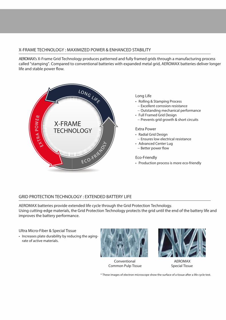
Ultra Micro-Fiber & Special Tissue Increases plate durability by reducing the aging-
rate of active materials.
* These images of electron microscope show the surface of a tissue after a life cycle test.
ConventionalCommon Pulp Tissue
AEROMAXSpecial Tissue
Long Life Rolling & Stamping Process
" Excellent corrosion resistance " Outstanding mechanical performance
Full Framed Grid Design " Prevents grid growth & short circuits
Extra Power Radial Grid Design
" Ensures low electrical resistance Advanced Center Lug
" Better power #ow
Eco-Friendly Production process is more eco-friendlyE C O -FR IE
ND
LY
LONG
LIFE
EXTR
A
POW
ER
X-FRAME TECHNOLOGY : MAXIMIZED POWER & ENHANCED STABILITY
AEROMAX’s X-Frame Grid Technology produces patterned and fully framed grids through a manufacturing process called "stamping". Compared to conventional batteries with expanded metal grid, AEROMAX batteries deliver longer life and stable power #ow.
GRID PROTECTION TECHNOLOGY : EXTENDED BATTERY LIFE
AEROMAX batteries provide extended life cycle through the Grid Protection Technology. Using cutting-edge materials, the Grid Protection Technology protects the grid until the end of the battery life and improves the battery performance.
X-FRAME TECHNOLOGY

GET ALLTHE POWER
YOU NEED

Gr. No Type No.Capacity CCA Dimension (mm)
Layout Terminal Hold-Down(20HR) (JIS:SAE/DIN:EN) L W H TH
B19 UMF55B19R 45 400 187 127 200 220 1 B B0(B1)
B19 UMF55B19L 45 400 187 127 200 220 0 B B0(B1)
B19 UMF55B19RS 45 400 187 127 200 220 1 A B0(B1)
B19 UMF55B19LS 45 400 187 127 200 220 0 A B0(B1)
B24 UMF75B24R 55 500 234 127 200 220 1 B B0(B1)
B24 UMF75B24L 55 500 234 127 200 220 0 B B0(B1)
B24 UMF75B24RS 55 500 234 127 200 220 1 A B0(B1)
B24 UMF75B24LS 55 500 234 127 200 220 0 A B0(B1)
D23 UMF95D23R 75 700 230 172 200 220 1 A B0(B1)
D23 UMF95D23L 75 700 230 172 200 220 0 A B0(B1)
D26 UMF115D26R 85 750 257 172 200 220 1 A B0(B1)
D26 UMF115D26L 85 750 257 172 200 220 0 A B0(B1)
D31 UMF135D31R 100 850 302 172 200 220 1 A B0(B1)
D31 UMF135D31L 100 850 302 172 200 220 0 A B0(B1)
L2 UMF56800 68 600 242 174 190 190 0 A B13
L2 UMF56801 68 600 242 174 190 190 1 A B13
LB3 UMF57400 74 750 277 174 175 175 0 A B13
LB3 UMF57401 74 750 277 174 175 175 1 A B13
L3 UMF57800 78 780 277 174 190 190 0 A B13
LB4 UMF58000 80 800 315 174 175 175 0 A B13
L4 UMF59000 90 800 315 174 190 190 0 A B13
L4 UMF59001 90 800 315 174 190 190 1 A B13
L5 UMF60500 105 850 354 174 190 190 0 A B13
L6 UMF61000 110 950 398 174 190 190 0 A B13
UHPB SPECIFICATIONS:
30% enhanced starting power for top level performance Fast and powerful start with X-Frame Grid Technology Enduring and consistent power performance with Grid Protection Technology Reinforced case to resist exterior damage and deformation Rapid charging through latest carbon plus technology
MAIN BENEFITS:
AEROMAX UHPB Battery is designed to provide ultimate performance for a wide range of premium vehicles that require higher power support.
UHPB BATTERIES Ultra High Performance Batteries

SATISFYINGHIGH ENERGYDEMANDS

HPB SPECIFICATIONS:
Gr. No Type No.Capacity CCA Dimension (mm)
Layout Terminal Hold-Down(20HR) (JIS:SAE/DIN:EN) L W H TH
B19 HMF50B19R 42 380 187 127 200 220 1 B B0
B19 HMF50B19L 42 380 187 127 200 220 0 B B0
B19 HMF50B19RS 42 380 187 127 200 220 1 A B0
B19 HMF50B19LS 42 380 187 127 200 220 0 A B0
B24 HMF65B24R 48 470 234 127 200 220 1 B B0
B24 HMF65B24L 48 470 234 127 200 220 0 B B0
B24 HMF65B24RS 48 470 234 127 200 220 1 A B0
B24 HMF65B24LS 48 470 234 127 200 220 0 A B0
D23 HMF90D23R 68 630 230 172 200 220 1 A B0
D23 HMF90D23L 68 630 230 172 200 220 0 A B0
D23 HMF90D23FR 68 630 230 172 200 220 1 A B1
D23 HMF90D23FL 68 630 230 172 200 220 0 A B1
D26 HMF100D26R 70 680 257 172 200 220 1 A B0
D26 HMF100D26L 70 680 257 172 200 220 0 A B0
D26 HMF100D26FR 70 680 257 172 200 220 1 A B1
D26 HMF100D26FL 70 680 257 172 200 220 0 A B1
D31 HMF120D31R 90 880 302 172 200 220 1 A B0
D31 HMF120D31L 90 880 302 172 200 220 0 A B0
D31 HMF120D31FR 90 880 302 172 200 220 1 A B1
D31 HMF120D31FL 90 880 302 172 200 220 0 A B1
L1 HMF55090 50 470 208 174 190 190 0 A B13
L1 HMF55091 50 470 208 174 190 190 1 A B13
L2 HMF56390 62 570 242 174 190 190 0 A B13
L2 HMF56391 62 570 242 174 190 190 1 A B13
L3 HMF57490 72 720 277 174 190 190 0 A B13
L3 HMF57491 72 720 277 174 190 190 1 A B13
L4 HMF58590 85 750 315 174 190 190 0 A B13
L4 HMF58591 85 750 315 174 190 190 1 A B13
L5 HMF60090 100 880 354 174 190 190 0 A B13
15% enhanced starting power for better performance Reliable start with X-Frame Grid Technology Powerful stability with Grid Protection Technology
MAIN BENEFITS:
You can trust AEROMAX HPB Battery for everyday driving activities with its extra power and durability. It provides the right power support you can rely on, even in harsh conditions.
HPB BATTERIES High Performance Batteries

RELIABLEPOWER SUPPORT
EVERY TIME

Gr. No Type No.Capacity CCA Dimension (mm)
Layout Terminal Hold-Down(20HR) SAE L W H TH
B19 MF40B19L 35 330 187 127 200 220 0 B B0
B19 MF40B19R 35 330 187 127 200 220 1 B B0
B19 MF40B19LS 35 330 187 127 200 220 0 A B0
B19 MF40B19RS 35 330 187 127 200 220 1 A B0
B19 MF40B19FL 35 330 187 127 200 220 0 B B1
B19 MF42B19L 38 350 187 127 200 220 0 B B0
B19 MF42B19R 38 350 187 127 200 220 1 B B0
B19 MF42B19LS 38 350 187 127 200 220 0 A B0
B19 MF42B19RS 38 350 187 127 200 220 1 A B0
B19 MF42B19FL 38 350 187 127 200 220 0 B B1
B19 MF44B19L 40 370 187 127 200 220 0 B B0
B19 MF44B19R 40 370 187 127 200 220 1 B B0
B19 MF44B19LS 40 370 187 127 200 220 0 A B0
B19 MF44B19RS 40 370 187 127 200 220 1 A B0
B19 MF44B19FL 40 370 187 127 200 220 0 B B1
B24 MF50B24L 45 400 234 127 200 220 0 B B0
B24 MF50B24R 45 400 234 127 200 220 1 B B0
B24 MF50B24LS 45 400 234 127 200 220 0 A B0
B24 MF50B24RS 45 400 234 127 200 220 1 A B0
B24 MF55B24L 45 430 234 127 200 220 0 B B0
B24 MF55B24R 45 430 234 127 200 220 1 B B0
B24 MF55B24LS 45 430 234 127 200 220 0 A B0
B24 MF55B24RS 45 430 234 127 200 220 1 A B0
B24 MF60B24L 48 460 234 127 200 220 0 B B0
B24 MF60B24R 48 460 234 127 200 220 1 B B0
B24 MF60B24LS 48 460 234 127 200 220 0 A B0
B24 MF60B24RS 48 460 234 127 200 220 1 A B0
D20 MF50D20L 50 450 200 172 200 220 0 A B1
Reliable starting power with X-Frame Grid Technology Grid Protection Technology delivers longer service life A complete range o$ered for 99% of vehicles on the market
MAIN BENEFITS:
AEROMAX SMF Battery is the ideal choice for standard vehicles with usual power demands. It’s maintenance free and it provides reliable power support for all applications. AEROMAX o!ers a complete range of SMF Batteries for all of European, Asian and American vehicles.
SMF SPECIFICATIONS:
FOR JAPANESE VEHICLES
SMF BATTERIES Sealed Maintenance Free Batteries
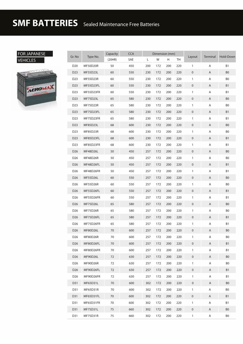
Gr. No Type No.Capacity CCA Dimension (mm)
Layout Terminal Hold-Down(20HR) SAE L W H TH
D20 MF50D20R 50 450 200 172 200 220 1 A B1
D23 MF55D23L 60 550 230 172 200 220 0 A B0
D23 MF55D23R 60 550 230 172 200 220 1 A B0
D23 MF55D23FL 60 550 230 172 200 220 0 A B1
D23 MF55D23FR 60 550 230 172 200 220 1 A B1
D23 MF75D23L 65 580 230 172 200 220 0 A B0
D23 MF75D23R 65 580 230 172 200 220 1 A B0
D23 MF75D23FL 65 580 230 172 200 220 0 A B1
D23 MF75D23FR 65 580 230 172 200 220 1 A B1
D23 MF85D23L 68 600 230 172 200 220 0 A B0
D23 MF85D23R 68 600 230 172 200 220 1 A B0
D23 MF85D23FL 68 600 230 172 200 220 0 A B1
D23 MF85D23FR 68 600 230 172 200 220 1 A B1
D26 MF48D26L 50 450 257 172 200 220 0 A B0
D26 MF48D26R 50 450 257 172 200 220 1 A B0
D26 MF48D26FL 50 450 257 172 200 220 0 A B1
D26 MF48D26FR 50 450 257 172 200 220 1 A B1
D26 MF55D26L 60 550 257 172 200 220 0 A B0
D26 MF55D26R 60 550 257 172 200 220 1 A B0
D26 MF55D26FL 60 550 257 172 200 220 0 A B1
D26 MF55D26FR 60 550 257 172 200 220 1 A B1
D26 MF75D26L 65 580 257 172 200 220 0 A B0
D26 MF75D26R 65 580 257 172 200 220 1 A B0
D26 MF75D26FL 65 580 257 172 200 220 0 A B1
D26 MF75D26FR 65 580 257 172 200 220 1 A B1
D26 MF80D26L 70 600 257 172 200 220 0 A B0
D26 MF80D26R 70 600 257 172 200 220 1 A B0
D26 MF80D26FL 70 600 257 172 200 220 0 A B1
D26 MF80D26FR 70 600 257 172 200 220 1 A B1
D26 MF90D26L 72 630 257 172 200 220 0 A B0
D26 MF90D26R 72 630 257 172 200 220 1 A B0
D26 MF90D26FL 72 630 257 172 200 220 0 A B1
D26 MF90D26FR 72 630 257 172 200 220 1 A B1
D31 MF65D31L 70 600 302 172 200 220 0 A B0
D31 MF65D31R 70 600 302 172 200 220 1 A B0
D31 MF65D31FL 70 600 302 172 200 220 0 A B1
D31 MF65D31FR 70 600 302 172 200 220 1 A B1
D31 MF75D31L 75 660 302 172 200 220 0 A B0
D31 MF75D31R 75 660 302 172 200 220 1 A B0
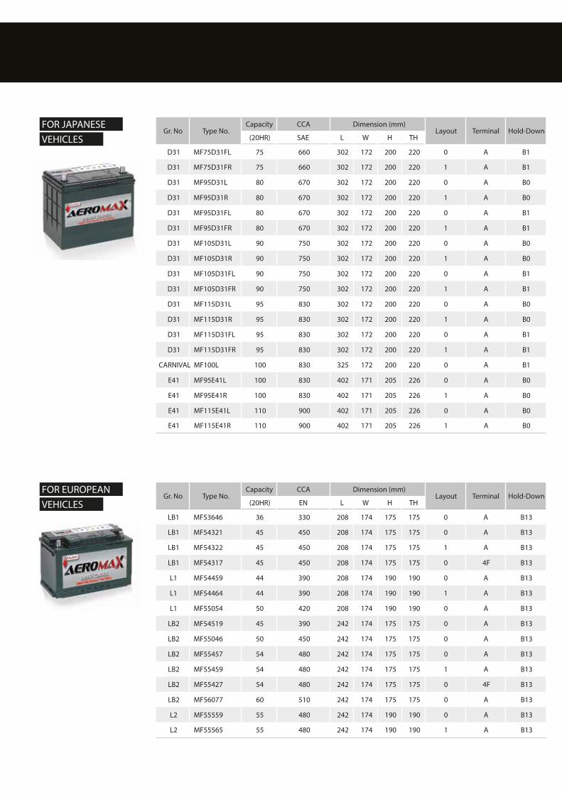
FOR JAPANESE VEHICLES
SMF BATTERIES Sealed Maintenance Free Batteries
Gr. No Type No.Capacity CCA Dimension (mm)
Layout Terminal Hold-Down(20HR) EN L W H TH
LB1 MF53646 36 330 208 174 175 175 0 A B13
LB1 MF54321 45 450 208 174 175 175 0 A B13
LB1 MF54322 45 450 208 174 175 175 1 A B13
LB1 MF54317 45 450 208 174 175 175 0 4F B13
L1 MF54459 44 390 208 174 190 190 0 A B13
L1 MF54464 44 390 208 174 190 190 1 A B13
L1 MF55054 50 420 208 174 190 190 0 A B13
LB2 MF54519 45 390 242 174 175 175 0 A B13
LB2 MF55046 50 450 242 174 175 175 0 A B13
LB2 MF55457 54 480 242 174 175 175 0 A B13
LB2 MF55459 54 480 242 174 175 175 1 A B13
LB2 MF55427 54 480 242 174 175 175 0 4F B13
LB2 MF56077 60 510 242 174 175 175 0 A B13
L2 MF55559 55 480 242 174 190 190 0 A B13
L2 MF55565 55 480 242 174 190 190 1 A B13
Gr. No Type No.Capacity CCA Dimension (mm)
Layout Terminal Hold-Down(20HR) SAE L W H TH
D31 MF75D31FL 75 660 302 172 200 220 0 A B1
D31 MF75D31FR 75 660 302 172 200 220 1 A B1
D31 MF95D31L 80 670 302 172 200 220 0 A B0
D31 MF95D31R 80 670 302 172 200 220 1 A B0
D31 MF95D31FL 80 670 302 172 200 220 0 A B1
D31 MF95D31FR 80 670 302 172 200 220 1 A B1
D31 MF105D31L 90 750 302 172 200 220 0 A B0
D31 MF105D31R 90 750 302 172 200 220 1 A B0
D31 MF105D31FL 90 750 302 172 200 220 0 A B1
D31 MF105D31FR 90 750 302 172 200 220 1 A B1
D31 MF115D31L 95 830 302 172 200 220 0 A B0
D31 MF115D31R 95 830 302 172 200 220 1 A B0
D31 MF115D31FL 95 830 302 172 200 220 0 A B1
D31 MF115D31FR 95 830 302 172 200 220 1 A B1
CARNIVAL MF100L 100 830 325 172 200 220 0 A B1
E41 MF95E41L 100 830 402 171 205 226 0 A B0
E41 MF95E41R 100 830 402 171 205 226 1 A B0
E41 MF115E41L 110 900 402 171 205 226 0 A B0
E41 MF115E41R 110 900 402 171 205 226 1 A B0
FOR JAPANESE VEHICLES
FOR EUROPEAN VEHICLES
Gr. No Type No.Capacity CCA Dimension (mm)
Layout Terminal Hold-Down(20HR) EN L W H TH
L2 MF55531 55 480 242 174 190 190 0 4F B13
L2 MF56219 62 540 242 174 190 190 0 A B13
L2 MF56220 62 540 242 174 190 190 1 A B13
L2 MF56221 62 540 242 174 190 190 0 4F B13
LB3 MF55415 54 480 277 174 175 175 0 A B13
LB3 MF56318 63 540 277 174 175 175 0 A B13
LB3 MF56828 68 570 277 174 175 175 0 A B13
LB3 MF56821 68 570 277 174 175 175 1 A B13
LB3 MF56818 68 570 277 174 175 175 0 4F B13
LB3 MF57113 72 640 277 174 175 175 0 A B13
L3 MF56638 66 540 277 174 190 190 0 A B13
L3 MF56633 66 540 277 174 190 190 1 A B13
L3 MF57220 72 610 277 174 190 190 0 A B13
L3 MF57219 72 610 277 174 190 190 1 A B13
L3 MF57412 74 680 277 174 190 190 0 A B13
L3 MF57413 74 680 277 174 190 190 1 A B13
LB4 MF57539 75 640 315 174 175 175 0 A B13
L4 MF58043 80 640 315 174 190 190 0 A B13
LB5 MF58515 85 720 354 174 175 175 0 A B13
L5 MF58827 88 680 354 174 190 190 0 A B13
L5 MF58821 88 680 354 174 190 190 1 A B13
L5 MF59218 92 720 354 174 190 190 0 A B13
L5 MF60038 100 850 354 174 190 190 0 A B13
B19 MF53520 35 330 187 127 200 220 0 B B0
B19 MF53522 35 330 187 127 200 220 1 B B0
B19 MF53504 35 330 187 136 200 220 0 B B1
B19 MF54026 40 360 187 127 200 220 0 B B0
B19 MF54027 40 360 187 127 200 220 1 B B0
B24 MF54523 45 360 234 127 200 220 0 A B0
B24 MF54524 45 360 234 127 200 220 1 A B0
B24 MF54584 45 360 234 127 200 220 0 B B0
B24 MF54551 45 360 234 127 200 220 1 B B0
D20 MF55041 50 390 200 172 200 220 0 A B1
D20 MF55042 50 390 200 172 200 220 1 A B1
D23 MF56068 60 480 230 172 200 220 0 A B1
D23 MF56069 60 480 230 172 200 220 1 A B1
D26 MF56048 60 480 257 172 200 220 0 A B1
D26 MF56049 60 480 257 172 200 220 1 A B1
D26 MF57024 70 540 257 172 200 220 1 A B1
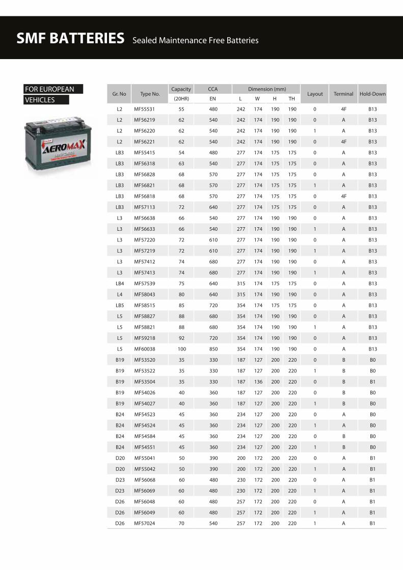
FOR EUROPEAN VEHICLES
SMF BATTERIES Sealed Maintenance Free Batteries

Gr. No Type No.RC CCA Dimension (mm)
Layout Terminal Hold-Down BCI Assembly Figure No.(MIN) SAE L W H TH
51 MF51-430 71 430 234 136 200 220 1 A B1 10
51 MF51-460 78 460 234 136 200 220 1 A B1 10
51R MF51R-430 71 430 234 136 200 220 0 A B1 11
51R MF51R-460 78 460 234 136 200 220 0 A B1 11
21 MF21-450 80 450 200 172 200 220 1 A B1 10
21 MF21-500 88 500 200 172 200 220 1 A B1 10
21R MF21R-450 80 450 200 172 200 220 0 A B1 11
21R MF21R-500 88 500 200 172 200 220 0 A B1 11
26 MF26-450 80 450 208 172 180 200 1 A B1 10
26 MF26-550 100 550 208 172 180 200 1 A B1 10
26R MF26R-450 80 450 208 172 180 200 0 A B1 11
26R MF26R-550 100 550 208 172 180 200 0 A B1 11
85 MF85-500 85 500 230 172 180 200 0 A B1 11
85 MF85-550 90 550 230 172 180 200 0 A B1 11
86(85R) MF85R-500 85 500 230 172 180 200 1 A B1 10
86(85R) MF85R-550 90 550 230 172 180 200 1 A B1 10
34 MF34-550 100 550 260 172 180 200 1 A B1 10
34 MF34-630 125 630 260 172 180 200 1 A B1 10
34 MF34-670 130 670 260 172 180 200 1 A B1 10
34 MF34-710 140 710 260 172 180 200 1 A B1 10
34 MF34-750 155 750 260 172 180 200 1 A B1 10
34R MF34R-550 100 550 260 172 180 200 0 A B1 11
34R MF34R-630 125 630 260 172 180 200 0 A B1 11
34R MF34R-670 130 670 260 172 180 200 0 A B1 11
34R MF34R-710 140 710 260 172 180 200 0 A B1 11
Gr. No Type No.Capacity CCA Dimension (mm)
Layout Terminal Hold-Down(20HR) EN L W H TH
D26 MF57029 70 540 257 172 200 220 0 A B1
D31 MF57512 75 600 302 172 200 220 0 A B1
D31 MF57513 75 600 302 172 200 220 1 A B1
D31 MF58513 85 680 302 172 200 220 0 A B1
D31 MF58514 85 680 302 172 200 220 1 A B1
D31 MF59518 95 720 302 172 200 220 0 A B1
D31 MF59519 95 720 302 172 200 220 1 A B1
D31 MF60045 100 800 302 172 200 220 0 A B1
D31 MF60046 100 800 302 172 200 220 1 A B1
FOR EUROPEAN VEHICLES
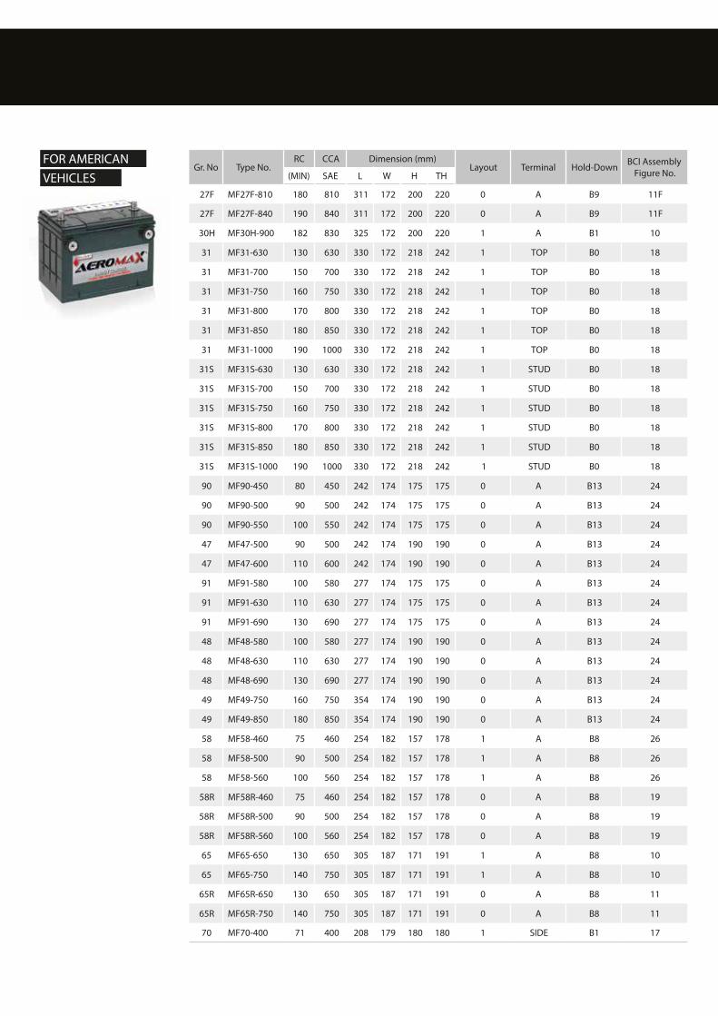
FOR AMERICAN VEHICLES

Gr. No Type No.RC CCA Dimension (mm)
Layout Terminal Hold-Down BCI Assembly Figure No.(MIN) SAE L W H TH
34R MF34R-750 155 750 260 172 180 200 0 A B1 11
25 MF25-550 100 550 230 172 200 220 1 A B1 10
25 MF25-580 110 580 230 172 200 220 1 A B1 10
35 MF35-550 100 550 230 172 200 220 0 A B1 11
35 MF35-580 110 580 230 172 200 220 0 A B1 11
24 MF24-450 80 450 257 172 200 220 1 A B1 10
24 MF24-500 90 500 257 172 200 220 1 A B1 10
24 MF24-550 100 550 257 172 200 220 1 A B1 10
24 MF24-600 113 600 257 172 200 220 1 A B1 10
24 MF24-630 130 630 257 172 200 220 1 A B1 10
24 MF24-680 140 680 257 172 200 220 1 A B1 10
24 MF24-750 155 750 257 172 200 220 1 A B1 10
24R MF24R-450 80 450 257 172 200 220 0 A B1 11
24R MF24R-500 90 500 257 172 200 220 0 A B1 11
24R MF24R-550 100 550 257 172 200 220 0 A B1 11
24R MF24R-600 113 600 257 172 200 220 0 A B1 11
24R MF24R-630 130 630 257 172 200 220 0 A B1 11
24R MF24R-680 140 680 257 172 200 220 0 A B1 11
24R MF24R-750 155 750 257 172 200 220 0 A B1 11
24F MF24F-450 80 450 266 172 200 220 0 A B9 11F
24F MF24F-500 90 500 266 172 200 220 0 A B9 11F
24F MF24F-550 100 550 266 172 200 220 0 A B9 11F
24F MF24F-600 113 600 266 172 200 220 0 A B9 11F
24F MF24F-630 130 630 266 172 200 220 0 A B9 11F
24F MF24F-680 140 680 266 172 200 220 0 A B9 11F
24F MF24F-750 155 750 266 172 200 220 0 A B9 11F
27 MF27-630 130 630 302 172 200 220 1 A B1 10
27 MF27-670 140 670 302 172 200 220 1 A B1 10
27 MF27-750 155 750 302 172 200 220 1 A B1 10
27 MF27-810 180 810 302 172 200 220 1 A B1 10
27 MF27-840 190 840 302 172 200 220 1 A B1 10
27R MF27R-630 130 630 302 172 200 220 0 A B1 11
27R MF27R-670 140 670 302 172 200 220 0 A B1 11
27R MF27R-750 155 750 302 172 200 220 0 A B1 11
27R MF27R-810 180 810 302 172 200 220 0 A B1 11
27R MF27R-840 190 840 302 172 200 220 0 A B1 11
27F MF27F-630 130 630 311 172 200 220 0 A B9 11F
27F MF27F-670 140 670 311 172 200 220 0 A B9 11F
27F MF27F-750 155 750 311 172 200 220 0 A B9 11F
FOR AMERICAN VEHICLES
SMF BATTERIES Sealed Maintenance Free Batteries
FOR AMERICAN VEHICLES
Gr. No Type No.RC CCA Dimension (mm)
Layout Terminal Hold-Down BCI Assembly Figure No.(MIN) SAE L W H TH
27F MF27F-810 180 810 311 172 200 220 0 A B9 11F
27F MF27F-840 190 840 311 172 200 220 0 A B9 11F
30H MF30H-900 182 830 325 172 200 220 1 A B1 10
31 MF31-630 130 630 330 172 218 242 1 TOP B0 18
31 MF31-700 150 700 330 172 218 242 1 TOP B0 18
31 MF31-750 160 750 330 172 218 242 1 TOP B0 18
31 MF31-800 170 800 330 172 218 242 1 TOP B0 18
31 MF31-850 180 850 330 172 218 242 1 TOP B0 18
31 MF31-1000 190 1000 330 172 218 242 1 TOP B0 18
31S MF31S-630 130 630 330 172 218 242 1 STUD B0 18
31S MF31S-700 150 700 330 172 218 242 1 STUD B0 18
31S MF31S-750 160 750 330 172 218 242 1 STUD B0 18
31S MF31S-800 170 800 330 172 218 242 1 STUD B0 18
31S MF31S-850 180 850 330 172 218 242 1 STUD B0 18
31S MF31S-1000 190 1000 330 172 218 242 1 STUD B0 18
90 MF90-450 80 450 242 174 175 175 0 A B13 24
90 MF90-500 90 500 242 174 175 175 0 A B13 24
90 MF90-550 100 550 242 174 175 175 0 A B13 24
47 MF47-500 90 500 242 174 190 190 0 A B13 24
47 MF47-600 110 600 242 174 190 190 0 A B13 24
91 MF91-580 100 580 277 174 175 175 0 A B13 24
91 MF91-630 110 630 277 174 175 175 0 A B13 24
91 MF91-690 130 690 277 174 175 175 0 A B13 24
48 MF48-580 100 580 277 174 190 190 0 A B13 24
48 MF48-630 110 630 277 174 190 190 0 A B13 24
48 MF48-690 130 690 277 174 190 190 0 A B13 24
49 MF49-750 160 750 354 174 190 190 0 A B13 24
49 MF49-850 180 850 354 174 190 190 0 A B13 24
58 MF58-460 75 460 254 182 157 178 1 A B8 26
58 MF58-500 90 500 254 182 157 178 1 A B8 26
58 MF58-560 100 560 254 182 157 178 1 A B8 26
58R MF58R-460 75 460 254 182 157 178 0 A B8 19
58R MF58R-500 90 500 254 182 157 178 0 A B8 19
58R MF58R-560 100 560 254 182 157 178 0 A B8 19
65 MF65-650 130 650 305 187 171 191 1 A B8 10
65 MF65-750 140 750 305 187 171 191 1 A B8 10
65R MF65R-650 130 650 305 187 171 191 0 A B8 11
65R MF65R-750 140 750 305 187 171 191 0 A B8 11
70 MF70-400 71 400 208 179 180 180 1 SIDE B1 17
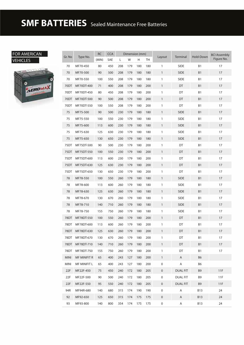
Gr. No Type No.RC CCA Dimension (mm)
Layout Terminal Hold-Down BCI Assembly Figure No.(MIN) SAE L W H TH
70 MF70-450 80 450 208 179 180 180 1 SIDE B1 17
70 MF70-500 90 500 208 179 180 180 1 SIDE B1 17
70 MF70-550 100 550 208 179 180 180 1 SIDE B1 17
70DT MF70DT-400 71 400 208 179 180 200 1 DT B1 17
70DT MF70DT-450 80 450 208 179 180 200 1 DT B1 17
70DT MF70DT-500 90 500 208 179 180 200 1 DT B1 17
70DT MF70DT-550 100 550 208 179 180 200 1 DT B1 17
75 MF75-500 90 500 230 179 180 180 1 SIDE B1 17
75 MF75-550 100 550 230 179 180 180 1 SIDE B1 17
75 MF75-600 113 600 230 179 180 180 1 SIDE B1 17
75 MF75-630 125 630 230 179 180 180 1 SIDE B1 17
75 MF75-650 130 650 230 179 180 180 1 SIDE B1 17
75DT MF75DT-500 90 500 230 179 180 200 1 DT B1 17
75DT MF75DT-550 100 550 230 179 180 200 1 DT B1 17
75DT MF75DT-600 113 600 230 179 180 200 1 DT B1 17
75DT MF75DT-630 125 630 230 179 180 200 1 DT B1 17
75DT MF75DT-650 130 650 230 179 180 200 1 DT B1 17
78 MF78-550 100 550 260 179 180 180 1 SIDE B1 17
78 MF78-600 113 600 260 179 180 180 1 SIDE B1 17
78 MF78-630 125 630 260 179 180 180 1 SIDE B1 17
78 MF78-670 130 670 260 179 180 180 1 SIDE B1 17
78 MF78-710 140 710 260 179 180 180 1 SIDE B1 17
78 MF78-750 155 750 260 179 180 180 1 SIDE B1 17
78DT MF78DT-550 100 550 260 179 180 200 1 DT B1 17
78DT MF78DT-600 113 600 260 179 180 200 1 DT B1 17
78DT MF78DT-630 125 630 260 179 180 200 1 DT B1 17
78DT MF78DT-670 130 670 260 179 180 200 1 DT B1 17
78DT MF78DT-710 140 710 260 179 180 200 1 DT B1 17
78DT MF78DT-750 155 750 260 179 180 200 1 DT B1 17
MINI MF MINIFIT R 65 400 243 127 180 200 1 A B6
MINI MF MINIFIT L 65 400 243 127 180 200 0 A B6
22F MF22F-450 75 450 240 172 180 205 0 DUAL FIT B9 11F
22F MF22F-500 90 500 240 172 180 205 0 DUAL FIT B9 11F
22F MF22F-550 95 550 240 172 180 205 0 DUAL FIT B9 11F
94R MF94R-680 140 680 315 174 190 190 0 A B13 24
92 MF92-650 125 650 315 174 175 175 0 A B13 24
93 MF93-800 140 800 354 174 175 175 0 A B13 24
FOR AMERICAN VEHICLES
SMF BATTERIES Sealed Maintenance Free Batteries

HOLD-DOWNB9
B9 (22F)
B13
B14
B1
B4
B6
B8
* For B0 there is no Hold-Down
slots on long sides, 29.0mm on short sides
slots on long sides, 29.0mm on short sides
19.0mm on all long sides, 10.5mm on short sides
10.5mm on all four sides
5 notches
5 notches
5 notches
19.0mm on long sides only
10.5mm on long sides only
13.5mm on long sides only
10.5
19.0
13.5
29.0
29.0
29.0
19.0
10.5
10.5
10.5
0
Length
LAYOUT FOR JIS & DIN 1
Length
TECHNICAL INFORMATION Layout, Terminals & Hold-Down
Terminal A (Standard) B (Small) Top Post Dual Fit 4F Stud Side
Positive
Negative
TERMINALS
3/8"-16 Threads
3/8"-16 Threads
* DT: Dual Terminal (Standard + Side)
LAYOUT FOR BCI
10
11F
18
24
11
17
19
26
L
W TH W TH
L
L
W TH
L
W TH
W TH
L
W TH
L
W
THL
W TH
L
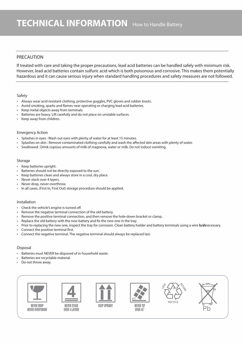
TECHNICAL INFORMATION How to Handle Battery
PRECAUTION
If treated with care and taking the proper precautions, lead acid batteries can be handled safely with minimum risk. However, lead acid batteries contain sulfuric acid which is both poisonous and corrosive. This makes them potentially hazardous and it can cause serious injury when standard handling procedures and safety measures are not followed.
Safety Always wear acid resistant clothing, protective goggles, PVC gloves and rubber boots. Avoid smoking, sparks and #ames near operating or charging lead acid batteries. Keep metal objects away from terminals. Batteries are heavy. Lift carefully and do not place on unstable surfaces. Keep away from children.
Emergency Action Splashes in eyes : Wash out eyes with plenty of water for at least 15 minutes. Splashes on skin : Remove contaminated clothing carefully and wash the a$ected skin areas with plenty of water. Swallowed : Drink copious amounts of milk of magnesia, water or milk. Do not induce vomiting.
Storage Keep batteries upright. Batteries should not be directly exposed to the sun. Keep batteries clean and always store in a cool, dry place. Never stack over 4 layers. Never drop, never overthrow. In all cases, (First In, First Out) storage procedure should be applied.
Installation Check the vehicle’s engine is turned o$. Remove the negative terminal connection of the old battery. Remove the positive terminal connection, and then remove the hole-down bracket or clamp. Replace the old battery with the new battery and !x the new one in the tray. Prior to replacing the new one, inspect the tray for corrosion. Clean battery holder and battery terminals using a wire brush, if necessary. Connect the positive terminal !rst. Connect the negative terminal. The negative terminal should always be replaced last.
Disposal Batteries must NEVER be disposed of in household waste. Batteries are recyclable material. Do not throw away.
GOODCONDITION
CHARGINGNECESSARY
REPLACEBATTERY
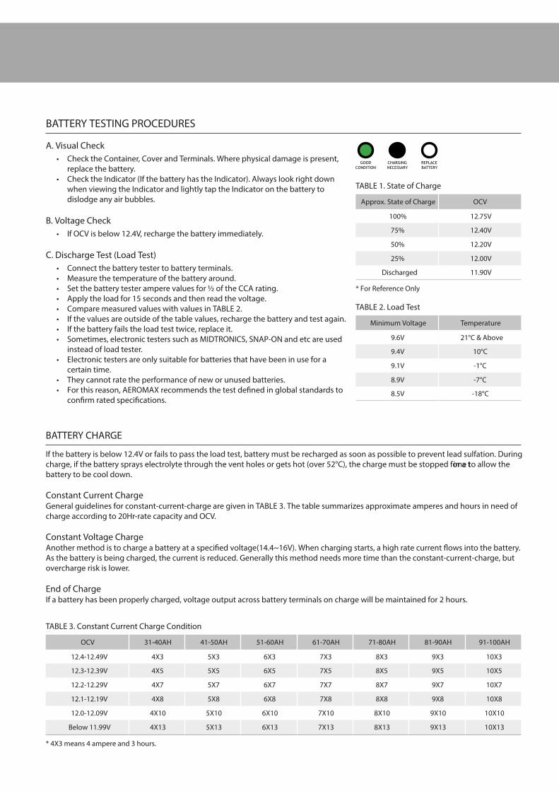
BATTERY TESTING PROCEDURES
A. Visual Check Check the Container, Cover and Terminals. Where physical damage is present,
replace the battery. Check the Indicator (If the battery has the Indicator). Always look right down
when viewing the Indicator and lightly tap the Indicator on the battery to dislodge any air bubbles.
B. Voltage Check If OCV is below 12.4V, recharge the battery immediately.
C. Discharge Test (Load Test) Connect the battery tester to battery terminals. Measure the temperature of the battery around. Set the battery tester ampere values for % of the CCA rating. Apply the load for 15 seconds and then read the voltage. Compare measured values with values in TABLE 2. If the values are outside of the table values, recharge the battery and test again. If the battery fails the load test twice, replace it. Sometimes, electronic testers such as MIDTRONICS, SNAP-ON and etc are used
instead of load tester. Electronic testers are only suitable for batteries that have been in use for a
certain time. They cannot rate the performance of new or unused batteries. For this reason, AEROMAX recommends the test de!ned in global standards to
con!rm rated speci!cations.
BATTERY CHARGE
If the battery is below 12.4V or fails to pass the load test, battery must be recharged as soon as possible to prevent lead sulfation. During charge, if the battery sprays electrolyte through the vent holes or gets hot (over 52°C), the charge must be stopped for a time to allow the battery to be cool down.
Constant Current ChargeGeneral guidelines for constant-current-charge are given in TABLE 3. The table summarizes approximate amperes and hours in need of charge according to 20Hr-rate capacity and OCV.
Constant Voltage ChargeAnother method is to charge a battery at a speci!ed voltage(14.4~16V). When charging starts, a high rate current #ows into the battery. As the battery is being charged, the current is reduced. Generally this method needs more time than the constant-current-charge, but overcharge risk is lower.
End of ChargeIf a battery has been properly charged, voltage output across battery terminals on charge will be maintained for 2 hours.
Approx. State of Charge OCV
100% 12.75V
75% 12.40V
50% 12.20V
25% 12.00V
Discharged 11.90V
* For Reference Only
TABLE 1. State of Charge
Minimum Voltage Temperature
9.6V 21°C & Above
9.4V 10°C
9.1V -1°C
8.9V -7°C
8.5V -18°C
TABLE 2. Load Test
OCV 31-40AH 41-50AH 51-60AH 61-70AH 71-80AH 81-90AH 91-100AH
12.4-12.49V 4X3 5X3 6X3 7X3 8X3 9X3 10X3
12.3-12.39V 4X5 5X5 6X5 7X5 8X5 9X5 10X5
12.2-12.29V 4X7 5X7 6X7 7X7 8X7 9X7 10X7
12.1-12.19V 4X8 5X8 6X8 7X8 8X8 9X8 10X8
12.0-12.09V 4X10 5X10 6X10 7X10 8X10 9X10 10X10
Below 11.99V 4X13 5X13 6X13 7X13 8X13 9X13 10X13
TABLE 3. Constant Current Charge Condition
* 4X3 means 4 ampere and 3 hours.

TECHNICAL INFORMATION Dimensions & Drawings
DIMENSIONS & DRAWINGS
Drawing No. JIS DIN BCIDimension (mm)
L W H TH
Drawing 1
B19
B24
53520
54523 51
187
234
127
127
200
200
220
220
Drawing 2 D20 55041 21 200 172 200 220
D23 56068 25/35 230 172 200 220
D26 24 257 172 200 220
D31 59518 27 302 172 200 220
26 208 172 180 200
34 260 172 180 200
85 230 172 180 200
Drawing 3
56048 24F
27F
266
311
172
172
200
200
220
220
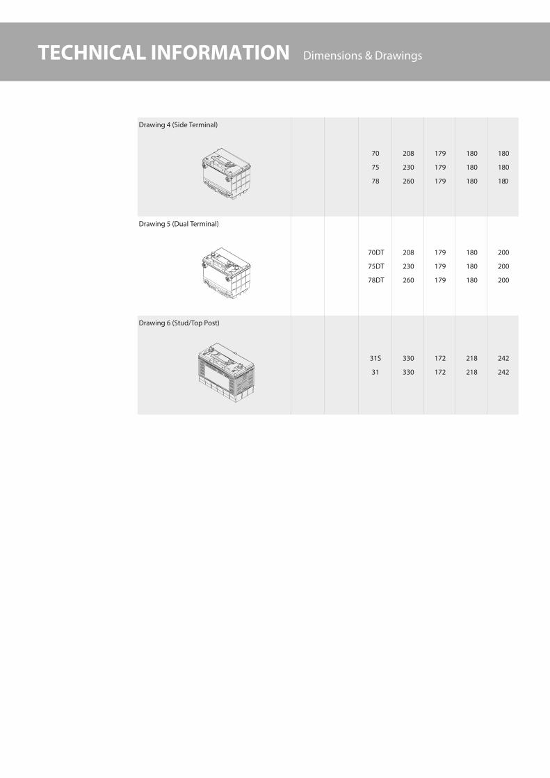
TECHNICAL INFORMATION Dimensions & Drawings
Drawing 4 (Side Terminal)
70
75
78
208
230
260
179
179
179
180
180
180
180
180
180
Drawing 5 (Dual Terminal)
70DT
75DT
78DT
208
230
260
179
179
179
180
180
180
200
200
200
Drawing 6 (Stud/Top Post)
31S
31
330
330
172
172
218
218
242
242
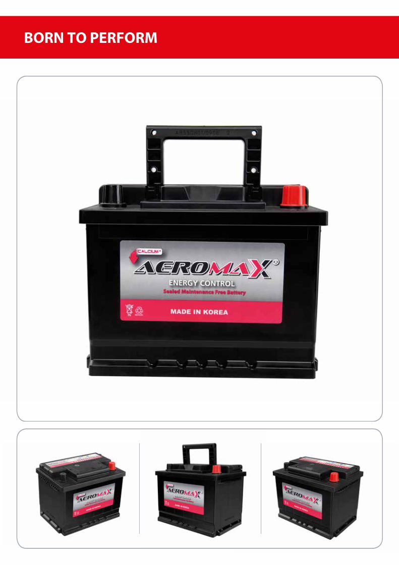
BORN TO PERFORM

www.bad iya .ae