the future of wireless communications in and around the...
TRANSCRIPT
VIRGINIA POLYTECHNIC INSTITUTEAND STATE UNIVERSITY
TechVirginia
1 8 7 2
© 1999 T. S. Rappaport, All Rights Reserved
Prof. Theodore S. Rappaport
Engineers of the Capitol BuildingDecember 10, 1999
Mobile and Portable Radio Research GroupBradley Dept. of Electrical and Computer Engineering
Virginia Techhttp://www.mprg.vt.edu
The Future of WirelessCommunications In and Around
the Office

©1999 T. S. Rappaport
vWireless communications services proliferatingrapidly
vConsumers about to enjoy unprecedentedmobility and flexibility for tetherless officeapplications
vE-mail, file transfers, and voice/datacommunications soon commonplace for currentusers of cellular phones
v State-of-the-art and future directions of wirelesscommunications for in-building applications
Abstract Details

©1999 T. S. Rappaport
Emerging Web Access Technologies
Source: C. Mason, “Can You Find the Wireless Runners?,” America’s Network, February 1, 1999,http://www.americasnetwork.com/.

©1999 T. S. Rappaport
Broadband Subscribers by Technology:U. S. Market in 2003
LMDS9%
ISDN12%
Satellite12%
Cable Modem
26%
ADSL36%
Others5%
Source: Allied Business Intelligence Inc.; L. Luna, “Internet Access Most Likely Use for LMDS,” RCR, August 24,1998, p. 3+.

©1999 T. S. Rappaport
Emerging Wireless Services
• Unified Messaging
• Wireless Local Loop (WLL)
• E-911/Position Location
• Mobile Satellite Services
• World Wide Wireless Web & Wireless Web Tablets
• Wireless in Small Office/Home Office (SoHo)
• 3G (Third Generation)

©1999 T. S. Rappaport
Wireless LANs
“Introduction to Wireless LANs,” The Wireless LAN Alliance, http://www.wlana.com.
vWireless LAN (WLAN): implemented asextension to or alternative for wired LAN withinbuildings or campus
vElectromagnetic waves transmit and receive datathrough air, minimizing wired connections
vData connectivity and user mobility combined

©1999 T. S. Rappaport
Wireless LANs in the Market Place
vSmall Businesses
vCorporations
vEducation
vFinance
vHealthcare
vHospitality and Retail
vManufacturing
vWarehousing

©1999 T. S. Rappaport
Wireless LAN Marketplace:Future Growth Expectations
Revenue1:í 1999: just over $400 millioní 2000: $550 millioní 2001: $700 millioní 2002: $830 millioní 2003: $1.1 billion
1Source: Frost & Sullivan, “Clear Signals For Wireless LANs”, Information Week Online, October 11, 19992Source: Cahner’s In-Stat Group (Scottsdale, AZ), “Wireless Data Users to Reach 25 Million by 2003,” Wireless Design Online,November 3, 1999.
Shipments1:í 1999: just under 1.5 millioní 2000: 2.2 millioní 2001: 3.4 millioní 2002: 4.75 millioní 2003: 6.2 billion
Users2:í 1.7 million todayí 25 million by 2003

©1999 T. S. Rappaport
Wireless LAN Marketplace
Baystack 600 SeriesWireless LANProducts1
• Access Point $1,4993
• PC Card $4993 Aironet PC4800 Turbo DS Series2
• Access Point $1,6953
• PC Card Adapter $5953
1 http://business.baynetworks.com/2 http://www.aironet.com/products/index.html3 http://www.gcn.com/vol18_no28/guide/514-2.html
©1999 T. S. Rappaport
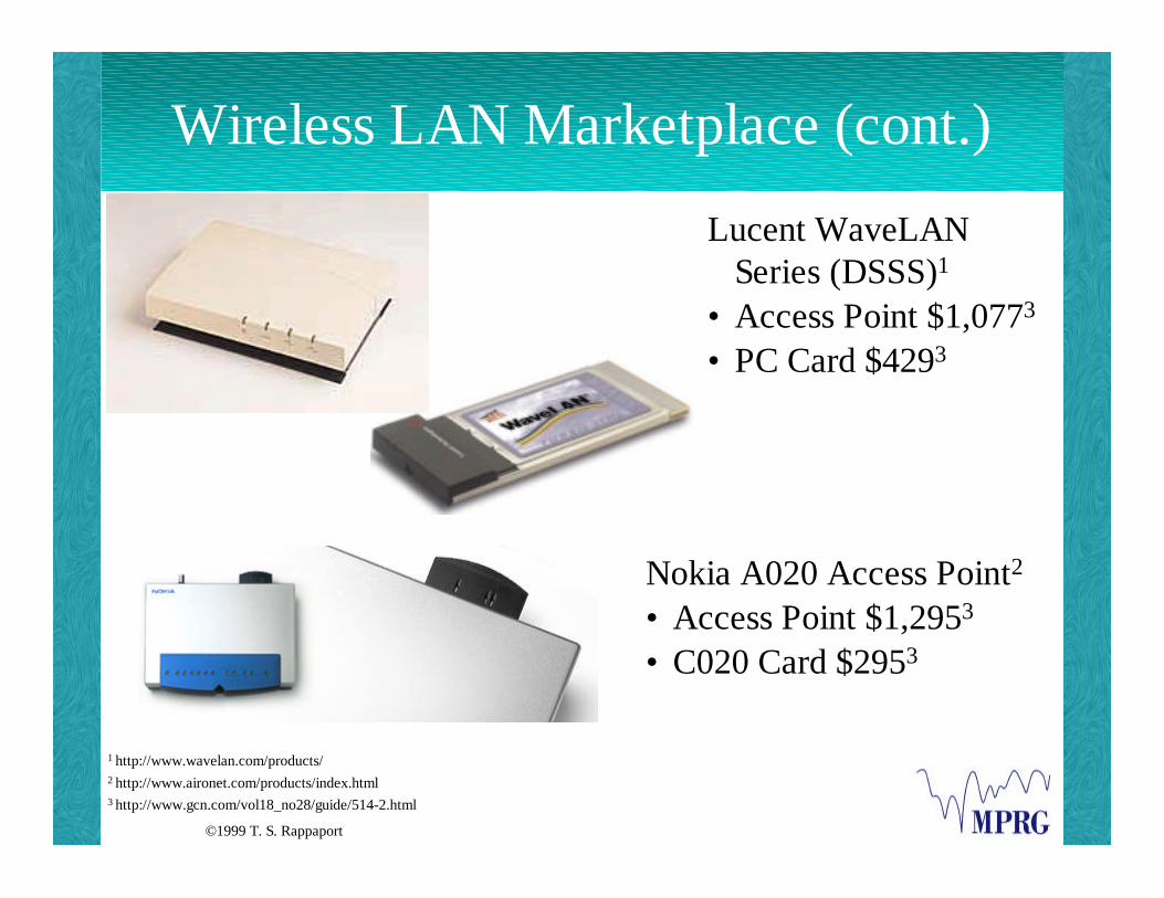
Wireless LAN Marketplace (cont.)
Lucent WaveLANSeries (DSSS)1
• Access Point $1,0773
• PC Card $4293
Nokia A020 Access Point2
• Access Point $1,2953
• C020 Card $2953
1 http://www.wavelan.com/products/2 http://www.aironet.com/products/index.html3 http://www.gcn.com/vol18_no28/guide/514-2.html

©1999 T. S. Rappaport
Benefits of Wireless LANs
vMobility: improves productivity, service
v Installation: fast, simple, flexible
vCost of Ownership: reduced over costs of wiredLAN hardware
v Scalability: easily configured to narrow or broadarea
“Introduction to Wireless LANs,” The Wireless LAN Alliance, http://www.wlana.com.

©1999 T. S. Rappaport
Applications of Wireless LANs
M. Sullivan, “State of the Wireless LAN Industry,” The Wireless LAN Alliance, http://www.wlana.com.
MainstreamApplications:
•Data Collection
•Inventory
•Point of Sale
•Hard-to-WireBuildings
BurgeoningApplications:
•BedsideMonitoring
•ER Check-in
•Financial Trading
•Cargo Tracking
•Outdoor Events
•HospitalityCheck-in
•StudentNetworking
AnticipatedApplications:
•Project Team Setup
•Virtual Offices
•Consulting Teams
•On-Site Training
•Mobile Intranet
•Customer-ReadyRooms
•Home Networking

©1999 T. S. Rappaport
IEEE 802.11 WLAN Standard
vDefines protocol for two types of networks: ad-hoc and client/server networks
v Ad-hoc network: communications are establishedbetween multiple stations in given coverage areawithout use of access point or server
v Client/server network: uses an access point thatcontrols the allocation of transmit time for all stationsand allows mobile stations to roam from cell to cell
v 2.4GHz unlicensed frequency band for data ratesof 1 and 2Mbps
“The IEEE 802.11 Wireless LAN Standard,” http://www.wlana.com/intro/standard/

©1999 T. S. Rappaport
IEEE 802.11 WLAN Standard (cont.)
vDoes not specify technology or implementation
v Simply specifies for the physical layer and MediaAccess Control (MAC) layer
“The IEEE 802.11 Wireless LAN Standard,” http://www.wlana.com/intro/standard/

©1999 T. S. Rappaport
In-Building and Campus DeploymentTools
Deterministic tools like SitePlanner™ , developed by researchers at MPRGand marketed by Wireless Valley Communications, Inc., leverage raytracing and other algorithms to provide system designers with acomprehensive package for designing and deploying indoor andmicrocellular wireless systems, including WLANs. Seehttp://www.wvcomm.com for more information.
R. J. Boyle, “Wireless Communications and Multipath Propagation: The Love-Hate Relationship,” presented at 1998Meeting of the American Institute of Physics’ Corporate Associates, October 26-27, 1998.
R. K. Morrow, “Site-Specific Engineering for Indoor Wireless Communications,” Applied Microwave and Wireless,March 1999, Vol. 11, No. 3, pp. 30-38.

©1999 T. S. Rappaport
In-Building Wireless Market(Cellular & PCS)
vAnnual growth rate for in-building wireless voicemarket expected to be 34%
v In-building market should reach revenues of morethan $800 million by 2003
v 169,000 mobile handsets shipped in 1998 for in-building applications; expected to be 1.2 millionhandsets shipped by 2003
Source: Phillips Group InfoTech, 1999

©1999 T. S. Rappaport
Dominant PCS Technologies in theWorld
• GSM (Global System for Mobile communications)
• CDMA (Code Division Multiple Access)
• TDMA (Time Division Multiple Access)
0
100
200
300
400
GSM CDMA TDMA
19972003
Source of Chart Information: Strategis Group’s “World Cellular/PCS Markets: 1998;” “Half of World’s WirelessSubs to Use GSM by 2003, Strategis Says,” RCR, June 8, 1998, p. 17.
Mill
ions
of S
ubsc
ribe
rs

©1999 T. S. Rappaport
3G (Third Generation Wireless)
http://devices.internet.com/glossary/glossary__a-h/glossary__a-h.html#3g
3G Third Generation Networks:
vNewest generation of mobile communications
vBased on GSM core and CDMA core
vAllows greater bandwidth, opening the way toincreased data-over-wireless solutions such assmart phones
vNot expected to be fully operational until 2002

©1999 T. S. Rappaport
3G (Third Generation Wireless)
“Third Generation Wireless Standards to Shape Internet's Future,” A WirelessNOW Feature by Geoff Livingston,http://www.commnow.com/3rd_Generation.html
Criteria for 3G Cellular Standards:
vMobile data rate of 144 Kbits per second
vPortable data rate of 384 Kbits per second
v In-building fixed data rate of 2 Mbits per second
©1999 T. S. Rappaport
IMT-2000: The Evolution of theStandard
vOriginally, IMT-2000 was to embrace a singleworldwide wireless standard
vUnable to unite 2G systems under one 3Gtechnology
v IMT-2000 will now be seen as a “family ofstandards” to ensure both current investments andglobal compatibility
Source: Personal Communications Newsletter, January 12, 1998

©1999 T. S. Rappaport
Key Features of IMT-2000
vEmphasizing worldwide commonality in design
vCompatibility of services within fixed networksand within IMT-2000
vHigh quality
vUse of small pocket-terminal worldwide andaccommodation of a variety of other types ofterminals
Source: “Frequently Asked Questions,” http://www.itu.int/imt/7_faqs/index.htm

©1999 T. S. Rappaport
Key Features of IMT-2000 (cont.)
vMobile users can connect to other mobile or fixedusers
vRange of voice and non-voice services available tomobile users
vCoverage areas services by more than one network
v Introduction of advanced technologies anddifferent applications made easy due to openarchitecture
Source: Working Document of Security Principles for FPLMTS, 1994

©1999 T. S. Rappaport
IMT-2000
Source: “Frequently Asked Questions,” http://www.itu.int/imt/7_faqs/index.htm
vThird Generation Systems
vAim to unify the diverse systems of today intoradio infrastructure capable of offering widerange of services around the year 2000 in manydifferent operating environments

©1999 T. S. Rappaport
IMT-2000
“ITU Approves IMT-2000 Specification,” Wireless Design Online, Nov. 9, 1999, http://www2.wirelessdesignonline.com/

©1999 T. S. Rappaport
Current Status of IMT-2000
v 10 terrestrial and 5 satellite proposals werereceived at ITU -- June, 1998
vReports by 16 independent evaluation groupssubmitted to ITU Task Group 8/1 -- September,1998
v Final selection of technologies -- March, 1999
Source: http://www.itu.int/newsroom/press/PP98/Documents/Backgrounder2IMT2000.htmlandhttp://www.itu.int/newsroom/press/releases/1999/99-22.html#1

©1999 T. S. Rappaport
Current Status of IMT-2000 (cont.)
v ITU-R Task Group 8/1 approved a comprehensiveset of terrestrial and satellite radio interfacespecifications for IMT-2000 -- November 1999
v Formal approval of the November 1999 IMT-2000Recommendations at the ITURadiocommunication Assembly -- May 2000
vCommercial operation of IMT-2000 services --2001
Source: http://www.itu.int/newsroom/press/PP98/Documents/Backgrounder2IMT2000.htmlandhttp://www.itu.int/newsroom/press/releases/1999/99-22.html#1
©1999 T. S. Rappaport
CDMA
vCode Division Multiple Access
v Spread spectrum technology (Qualcomm)
v cdma2000: TIA standard for 3G technology,submitted to ITU as part of the IMT-2000 3Gprocess
http://www.cdg.org/frame_cdg.html

©1999 T. S. Rappaport
CDMA Benefits to Users
v Increased capacity to 8 to 10 times that of AMPSanalog system and 4 to 5 times that of GSMsystem
vCall quality improved
v System planning simplified through use of samefrequency in every sector of every cell
http://www.cdg.org/frame_cdg.html

©1999 T. S. Rappaport
CDMA Benefits to Users (cont.)
vPrivacy enhanced
vCoverage characteristics improved, allowing forpossibility of fewer cell sites
vTalk time increased for portables
vBandwidth on demand
http://www.cdg.org/frame_cdg.html

©1999 T. S. Rappaport
CDMA: Channel/Cell Use
“About CDMA Technology: The CDMA Revolution,” http://www.cdg.org/frame_cdg.html
Before CDMA With CDMA
CDMA solves the capacity problem!

©1999 T. S. Rappaport
TDMA
vTime Division Multiple Access
vEuropean TDMA (GSM)
v Japanese TDMA (PHS/PDC)
vNorth American TDMA (IS-136)

©1999 T. S. Rappaport
TDMA Advantages
vTransmission Efficiency
vEasily adapted to data as well as voice
vNo interference from simultaneous transmissions
vExtended battery life and talk time for mobiles
vEfficient utilizes hierarchical cell, allowingcoverage to be tailored to support specific trafficand service needs
vDual-mode Handsets
“Time Division Multiple Access (TDMA) Tutorial,” http://www.webproforum.com/tdma/topic04.html

©1999 T. S. Rappaport
TDMA Disadvantages
vUsers have pre-definedtimeslots
v Subject to multipathdistortion
vLimited bandwidth
“Time Division Multiple Access (TDMA) Tutorial,” http://www.webproforum.com/tdma/topic05.html
©1999 T. S. Rappaport
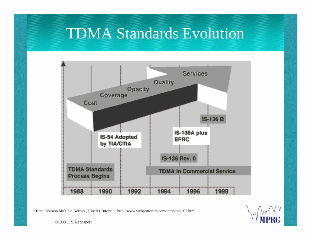
TDMA Standards Evolution
“Time Division Multiple Access (TDMA) Tutorial,” http://www.webproforum.com/tdma/topic07.html

©1999 T. S. Rappaport
LMDS
v Local Multi-Point Distribution Service at28GHZ -- campus distribution
v Wireless Communications Servicesv Two-way communicationsv High-speed communicationsv Datav Voicev Video

©1999 T. S. Rappaport
What are the benefits of LMDS?
v Low Cost:v bandwidth licenses inexpensive
v Fewer Environmental Issues:v air is medium, providing fairly constant environment;
CATV and telephone systems have more difficulties
v Easy to Deployv Modern Network:v do not have to rely on or maintain legacy systems or
services
D. Sweeney, “LMDS: Finally Ready for Prime Time?,” America’s Network, August 1, 1998.

©1999 T. S. Rappaport
What are the negatives of LMDS?
v Lack of Mature Technology:v largely undeveloped; untried service; little equipment available
v Lack of Experienced Personnel:v both relevant business experience in many of licensees and
qualified engineers
v No Leverage:v most licensees do not have customer base or existing
infrastructure
v Service Limits:v licensees cannot feasibly deliver service everywhere in
their market due to line-of-sight restriction for LMDS
D. Sweeney, “LMDS: Finally Ready for Prime Time?,” America’s Network, August 1, 1998.

©1999 T. S. Rappaport
LMDS
Source: WAVTRACE, August 1999

©1999 T. S. Rappaport
LMDS
Source: WAVTRACE, August 1999

©1999 T. S. Rappaport
Radio Wave Propagation at 38 GHz
View from Tx.
SCATTERINGREFLECTION
Burrus
Measurement Sites: Slusher - Whittemore Link (605 m)View from Rx.
H. Xu, T. S. Rappaport, R. J. Boyle, J. H. Schaffner, "38 GHz Wideband Point-to-Multipoint Radio Wave PropagationStudy for a Campus Environment," IEEE Vehicular Technology Conference, Houston, TX, May 16-19, 1999.

©1999 T. S. Rappaport
Radio Wave Propagation at 38 GHz
Measurement Results: Hail Attenuation Results
Attenuation due to hail: 25.7 dB.Hail size: 0.5-1.5 cm in diameter.
H. Xu, T. S. Rappaport, R. J. Boyle, J. H. Schaffner, "38 GHz Wideband Point-to-Multipoint Radio Wave PropagationStudy for a Campus Environment," IEEE Vehicular Technology Conference, Houston, TX, May 16-19, 1999.

©1999 T. S. Rappaport
Radio Wave Propagation at 38 GHz
Weather conditions:
• Hailstorm : Rain rate: 40 mm/hr Wind speed: 6 mile/hr Hail Diameter: 0.5-1.5cm
• Rain: Rain rate: 7.6 mm/hr Wind speed: 7 mile/hr
Analysis on MP Occurrence: Comparison of PDPs for Different Weather
H. Xu, T. S. Rappaport, R. J. Boyle, J. H. Schaffner, "38 GHz Wideband Point-to-Multipoint Radio Wave PropagationStudy for a Campus Environment," IEEE Vehicular Technology Conference, Houston, TX, May 16-19, 1999.

©1999 T. S. Rappaport
Bluetooth
Source: http://www.bluetooth.com/
vOpen specification for wireless communication ofdata and voice
vBased on low-cost short-range radio link
vBuilt into 9 x 9 mm microchip
v Facilitates protected ad hoc connections forstationary and mobile communicationenvironments

©1999 T. S. Rappaport
Bluetooth Benefits to End Users
vEasy, simple connectivity to wide range ofcomputing and telecommunications deviceswithout need to buy, carry, or connect cables
vOpportunities for rapid ad hoc connections
vPossibility of automatic, unconscious, connectionsbetween devices
vVirtually eliminates need to purchase additional orproprietary cabling to connect individual devices
“Frequently Asked Questions,” http://www.bluetooth.com/v2/faq/default.asp

©1999 T. S. Rappaport
Bluetooth Benefits to End Users(cont.)
vPotential replacement for multiple cableconnections via single radio link
vPossibility of using mobile data in a differentway, for different applications
vAllows users think about what they are workingon, rather than how to make their technologywork
“Frequently Asked Questions,” http://www.bluetooth.com/v2/faq/default.asp

©1999 T. S. Rappaport
Bluetooth Overview
vAllows for replacement of proprietary cablesconnecting one device to another with oneuniversal short-range radio link
vProvides universal bridge to existing datanetworks, peripherals, mechanisms to form smallprivate ad-hoc groupings of connected devicesaway from fixed network infrastructures
Source: http://www.bluetooth.com/
©1999 T. S. Rappaport
Bluetooth Overview (cont.)
vDevices designed to operate in noisy radiofrequency environment
vRadio uses fast acknowledgement and frequency hopping scheme to make linkrobust
vRadio modules avoid interference from othersignals by hopping to new frequency aftertransmitting or receiving packet
Source: http://www.bluetooth.com/

©1999 T. S. Rappaport
Bluetooth System Components
A Bluetooth system consists of the followingcomponents:
v Radio Unit
v Link Control Unit
v Link Management
v Software Functions
Source: http://www.bluetooth.com/
©1999 T. S. Rappaport
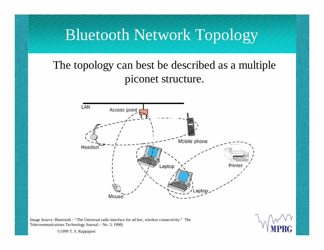
Bluetooth Network Topology
Image Source: Bluetooth – “The Universal radio interface for ad hoc, wireless connectivity.” TheTelecommunications Technology Journal – No. 3, 1998)
The topology can best be described as a multiplepiconet structure.
©1999 T. S. Rappaport
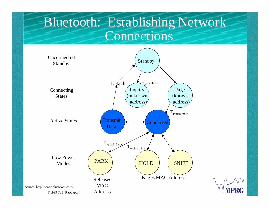
Bluetooth: Establishing NetworkConnections
Source: http://www.bluetooth.com/
UnconnectedStandby
ConnectingStates
Active States
Low PowerModes PARK HOLD SNIFF
Ttypical=0.6s
Detach Ttypical=2s
Standby
Inquiry(unknown address)
Page(known
address)
TransmitData
Connected
Ttypical=2 m s Ttypical=2 m s
ReleasesMAC
Address
Keeps MAC Address

©1999 T. S. Rappaport
Wireless Devices
E-PagerWireless Device(Internet e-mailaddress insteadof phonenumber)3
Ericcson’sBluetooth headset1
Qualcomm’s pdQ(cell phone andPalm Pilot)2
1 http://www.gadgetguru.com/CO---001971.HTML2 http://www.cnn.com/1999/TECH/ptech/12/03/qualcomm.pdq/index.html3 http://www.gadgetguru.com/CO---001926.HTML

©1999 T. S. Rappaport
Wireless Devices (cont.)
3Com/Palm’sPalm VII 3
Samsung Dual BandSCH 35001
Handspring’s VisorHandheld2
1 http://www.gadgetguru.com/CO---001981.HTML2 http://www.handspring.com/products/vgallery_visorincradle.asp3 http://www.palmpilot.com/custsupp/palmvii.html

©1999 T. S. Rappaport
Wireless Devices (cont.)
Qubit WebTabletAppliance 3
NeoPoint'sNP1000 DigitalSmart Phone1
Motorolai1000plus SmartPhone2
1 http://www.gadgetguru.com/CO---001882.HTML2 http://www.gadgetguru.com/CO---001882.HTML3 http://gadgetguru.com/CMPLM001777.HTML

©1999 T. S. Rappaport
Emerging Wideband WirelessSpectrum
Cellular, 50 MHz, 1983
PCS, 150 MHz, 1995
UNII, 300 MHz, 1997
LMDS, 1300 MHz, 1998
60 GHz Unlicensed, 5000 MHz, 1998
• A voice channel occupies » 10 kHz of spectrum.• A TV channel occupies » 5 MHz of spectrum.

©1999 T. S. Rappaport
5.85 GHz Residential Measurements: 5.85 GHz Applications
•January 1997: FCC allocated 300 MHz of spectrum in 5-6 GHz frequency bands•Unlicensed National Information Infrastructure (NII) devices•Applications for wide-bandwidth wireless local loops, public and private switched
telecommunications, and internet access•Similar spectrum in Europe allocated for HIPERLAN applications. MPRG did extensive
propagation study at 5.85 GHz and anticipates the development of lucrative consumer applicationsfor these frequencies
G. Durgin, T. S. Rappaport, H. Xu, “Measurements and Models for Radio Path Loss and Penetration Loss in and AroundHomes and Trees at 5.85 GHz,” IEEE Transactions on Communications, Vol. 46, No. 11, November 1998, pp. 1484-1496.
e
Houses
Moderately Wooded Yards
(160 m from Tranter Home)
tirie e v
oc oR c eL a ns
e
TxStreet
Trees
Trees
Trees
Trees
Tree
s
Trs

©1999 T. S. Rappaport
5.85 GHz Residential Measurements: Transmitter Configurations for
Residential Measurements
G. Durgin, T. S. Rappaport, H. Xu, “Measurements and Models for Radio Path Loss and Penetration Loss in and AroundHomes and Trees at 5.85 GHz,” IEEE Transactions on Communications, Vol. 46, No. 11, November 1998, pp. 1484-1496.
150-210 m30-45 m
1.5 m5.5 m
T Tx1 x2
Rx• One near transmitter (30-45m
from home) at 5.5m height
• One far transmitter (150-210m)from home at 5.5m height
MPRG Researcher GregDurgin sets up a 5.85 GHztransmitter unit from the backof the measurement van. Alltransmitters emulate curbsideneighborhood base stationsmounted atop 5.5m utilitypoles.

©1999 T. S. Rappaport
5.85 GHz Residential Measurements: Aggregate Penetration Loss Into a Home
This table provides typical5.85 GHz penetration lossthat are calculated from thedifference between indoorand outdoor measurements.
Shadowing LossHome TR sep 5.5 RX (dB) 1.5 RX (dB) APL (dB)Rappaport 30m 19.1 23.2 13.3
150m 10.8 11.9 16.4Woerner 30m 14.1 27.8 13.1
210m N/A N/A 7.2Tranter 48m 17.2 19.0 21.1
160m N/A N/A 15.316.3 23.6 16.3Linear Average
dB Average 15.3 20.5 14.4
G. Durgin, T. S. Rappaport, H. Xu, “Measurements and Models for Radio Path Loss and Penetration Loss in and AroundHomes and Trees at 5.85 GHz,” IEEE Transactions on Communications, Vol. 46, No. 11, November 1998, pp. 1484-1496.

©1999 T. S. Rappaport
5.85 GHz Propagation Modeling : The Need for 5.85 GHz Propagation Models
Statistical/EmpiricalModeling
Pseudo-DeterministicPropagation Modeling
DeterministicPropagation
Modeling
Computation Time
Site-Specific Information
Error/Standard Deviation
Measured Data
Future deployment of wireless 5-6GHz NII and HIPERLAN devices willrequire accurate propagationprediction models.
Key Question: How can weaccurately model signal power andinterference levels without invokingcomputational complexity or the needfor highly-detailed site information?
Solution: SitePlannerTM, a site-specific management tool spun out ofMPRG
G. Durgin, T. S. Rappaport, H. Xu, “Measurements and Models for Radio Path Loss and Penetration Loss in and AroundHomes and Trees at 5.85 GHz,” IEEE Transactions on Communications, Vol. 46, No. 11, November 1998, pp. 1484-1496.

©1999 T. S. Rappaport
5.85 GHz Propagation Modeling : Site-Specific Path Loss Map
40.2 45.0
31.3
51.4
33.4
52.6
32.4
51.3
33.7
54.4
31.8
53.6
32.0
29.6 33.0 48.5
31.3
50.7
25.9
51.0
27.3
57.9
32.1
56.5
32.0
1.5m Rx Ant. Path Loss
Indoor Path Loss
5.5m Rx Ant. Path Loss
Key
all values in dB w.r.t.1m FS
Rappaport Home - 30m TX Results
Tx
41.639.6
40.1
42.5 51.251.9
57.7
45.8
43.7
46.7
44.4 40.6
46.651.7
51.2Kitchen
Deck
First Floor
Second Floor
Garage
Tree
Tree
FrontBedroom
Rear Bed. 1
MasterBedroom
Rear Bed. 2Family Room
LivingRoom
DiningRoom
Office
G. Durgin, T. S. Rappaport, H. Xu, “Measurements and Models for Radio Path Loss and Penetration Loss in and AroundHomes and Trees at 5.85 GHz,” IEEE Transactions on Communications, Vol. 46, No. 11, November 1998, pp. 1484-1496.

©1999 T. S. Rappaport
5.85 GHz Propagation Modeling : Comparison of Standard Deviation
TR ConfigurationPL Exp.
nStd. Dev.σ (dB)
# of Meas.Points, Ν
# ofHomes
IndoorOverallFirst FloorSecond Floor
3.43.53.3
8.08.37.3
965838
333
OutdoorOverall1.5m5.5m
2.92.93.0
7.99.06.4
1477374
333
RappaportFirst FloorSecond Floor1.5m Outdoor5.5m Outdoor
3.53.53.13.0
9.77.410.26.5
23102627
1111
WoernerFirst FloorSecond Floor1.5m Outdoor5.5m Outdoor
3.23.32.93.1
6.27.78.26.2
8222220
1111
TranterFirst FloorSecond Floor1.5m Outdoor5.5m Outdoor
3.63.42.72.8
6.93.16.45.3
8272626
1111
PartitionLoss(dB)
TreeExterior WallInterior WallCinderblock/Basement
8.212.64.124
Standard Deviation 3.5
The above partitions resultfrom optimizing over allhome measurements withonly four basic partition types(tree, interior & exterior wall,and Cinderblock/Basement).
Path Loss Exponent ModelStandard Deviation: 8.0 dB
Partition-Based ModelStandard Deviation: 3.5 dB
G. Durgin, T. S. Rappaport, H. Xu, “Measurements and Models for Radio Path Loss and Penetration Loss in and AroundHomes and Trees at 5.85 GHz,” IEEE Transactions on Communications, Vol. 46, No. 11, November 1998, pp. 1484-1496.

©1999 T. S. Rappaport
Wireless Application Protocol (WAP)
“Frequently Asked Questions,” The Wireless Application Protocol Forum, http://www.wapforum.org/faqs/index.html.
vOpen, global specification
vEmpowers mobile users with wireless devicesto easily access and interact with informationand services instantly

©1999 T. S. Rappaport
WAP (cont.)
“Frequently Asked Questions,” The Wireless Application Protocol Forum, http://www.wapforum.org/faqs/index.html.
vWAP devices: handheld digital wireless
vWAP network compatibility: includesCDMA, GSM, TDMA, DECT and mostothers
vWAP complies with Third Generation (3G)wireless standards

©1999 T. S. Rappaport
WAP Benefits to Subscribers
vAccess from wireless handsets is quick andefficient for essential information.
vTransactions are secure.
v Interface is easy to use and meets the user’sneeds within the restrictions of a constrainednetwork device.
“WAP: Wireless Internet Today,” White Paper from The Wireless Application Protocol Forum,http://www.wapforum.org/what/WAP_white_pages.pdf.
©1999 T. S. Rappaport
WAP Benefits with WidespreadAdoption
vCommon user interface
vUbiquity of service
vWide selection of devices
vLarge selection of applications
“WAP: Wireless Internet Today,” White Paper from The Wireless Application Protocol Forum,http://www.wapforum.org/what/WAP_white_pages.pdf.

©1999 T. S. Rappaport
Conclusions
vNumerous specifications and standards aredeveloping to make devices more universaland compatible
vWireless Offices are no longer just an idea forthe future but are available today
vWireless, computing and the internet are allconverging rapidly into personal workappliances