the german giants
TRANSCRIPT

The GermanGiants
The German R-Planes1914-1918
GWHaddowPeter M Grosz

The GermanGiants
R-Planes 1914-1918

The GermanGiants
The German R-Planes1914-1918
GWHaddowPeter M Grosz

'() 1962 G. W. Haddow & Peter M. Grosz
First Published July 1962Reprinted September 1963Second Edition April 1969
Third Edition 1988ISBN 0 85177 812 7
Acknow ledgemen ts
Introduction
PART I
CONTENTS
IV
VII
Flight Log of Staaken R. V 13115 52
Organization of R-plane Troops 53
List of German Army Air Service Officers who died whileattached to R-plane Units 55
Operational Missions of Rfa 501 (Eastern Front) 56
Statistical Comparison of Bombengeschwader 3 and Rfa 501during the England Raids 56
Chart of R-plane Raids on England 57
Operational Missions of Rfa 500 and Rfa 501 (Western Front) 58
Performance of R-planes on Combat Missions 59
Operational R-plane Losses 61
Projected Delivery Dates for R-planes 62
List of R-planes to be completed after 31 January 1919 63
Description of German Bombs 64
What is an R-plane '!
Operational History
Eastern Front Operations
R-plane Raids on England
Western Front Operation
Operational Losses
Post-War Operations
"However, if 1 had waited long enough 1 probably never would have wriffenanything at all since there is a tendency when you really begin to learn somethingabout a thing not to want to write about it, but rather to keep on learning aboutit always, and at no time unless you are very egotistical which of course accountsfor many books wi!! you be able to say 'now I know all about this and wi!! writeabout it."
Ernest Hemingway Death in the AjiernooJl
Appendix
Appendix 2
Appendix 3
Appendix ~
Appendi>.. "Appendix 6
Appendix 7
Appendix 8
Appendix 9
Appendix 10
Appendix II
Appendix 12
Appendix 13
Appendix I~
Chart of R-plane umbers. Dimensions and Performance
Sikorsky "Ilia Mourumetz"
9
10
25
39
44
47
67
70
PART II
Description of R-plane Types (Alphabetically)
Selected Bibliography
Index A Aeroplanes
Printed and bound in Creat Britain forPutnam, an imprint of Conway Maritime Press Ltd.,
24 Bride Lane, Fleet Street,London EC4 Y 8DR
at the University Printing House, Oxford
Index B General Subjects
73
303
305
307
III

Staakcn tcst pilots commemorating the completion of the 25th Staaken R-plane, an R.XIVa. Thirdfrom thc right IS Willy Mann who flew the first R-planc built by VGO.
ACKNOWLEDGEMENTS
The authors owe a great debt of gratitude to the many individuals andorganizations who so freely and graciously contributed to the compilationof this book. Particular mention is due to those veterans (now alas, veryfew) who actually participated in the development and operation of theR-planes; they extended to us their records and recollections of thoseearly days and generously allowed us to use photographs from theiralbums. Our sincere thanks go to: Obit. a. D. Max Borchers, one ofthe first members of Rfa 501 and last commander of Rfa 500; PaulBi.ittner, a ground crew member in charge of gyro-compass installationand servicing, whose excellent descriptions provided much backgroundmaterial on the activities of Rfa 501; Oberstabsingenieur a. D. HansHeitmann, a foreman at SSW, for his fact-filled and often amusinganecdotes of flights at Doberitz and at the Front; Dipl.-Ing. Wilhelm Hillmann, active as a designer in the early aircraft activities of Schlitte-Lanz;Hptm. a. D. George Krupp, who first organized and commanded Rfa 501and later in the war was active in the testing and development of newR-planes for Jdflieg; Carl Kuring, second pilot and only survivor of the
ill-fated RML.I (VGO.I) and later test pilot of the Staaken E.4/20;Dipl.-Tng. Richard Llihr, technical officer of Rfa 500 during the early dayson the Eastern Front; Wilhelm Pfaff, who served in Rfa 500 during thelast months of the war and, as an engine mechanic on the R.45, participated in several born bing raids; Bruno Steffen, designer and test pilot,who provided much interesting material regarding the Siemens-SchuckertR-planes; Dipl.-Ing. Harald Wolff, chief of the SSW aircraft designbureau during the war, and to Frau E. von Bentivegni for details concerning the life of her husband, the long-term commander of Rfa 501. Workingwith the above has been a rewarding pleasure, and we hope they haveenjoyed reminiscing about the past as much as we have enjoyed hearingand reading their stories.
Our thanks and appreciation go also to the many air hi torians andenthusiasts who helped so much in providing material and photographs,in particular: the late A. R. Weyl, co-author of the classic engineering texton R-planes; Egon Krueger, who contributed valuable original material;Dr. Douglas Robinson for his friendly criticism and knowledge of German
aval history. AI 0, the following who generously provided assistancedeserve our thanks: Mes rs. Peter M. Bower, Rex Brown, Bud R. Erb,Frank L. Greene, Alex Imrie, Albert L. Lang, Heinz Nowarra, William R.Puglisi, William W. Richardson and Douglas Whiffen.
Our thanks also to Rear Admiral E. M. Eller, USN (Ret.). Director ofNaval History, through whose kind offices the German Naval Archiveswere made available for inspection; A. J. Charge, Keeper of Photographsat the Imperial War Museum, London; The Still Photo Collection,USAF, Washington; Archiv fur Fluggeschichte und Luftschiffahrt,Berlin; Luftfahrt-Verlag Walter Zuerl, Munich; and the U.S. Air ForceMuseum, Dayton.
The authors also wish to express their thanks to Mrs. Peter Grosz forvaluable assistance in preparing the manuscript.
ACKNOWLEDGEMENTS TO THE 2ND EDITION
New contacts with surviving R-plane personnel, brought about bypublication of The German Giants six years ago, has added many detailsto the story of these fascinating machines, and made possible this revisedsecond edition.
We would like to extend our appreciation and thanks to all the followingwho were involved in the development of R-planes. Phillip Simon, theman responsible for quality control and stressing at VGO-Staaken, forhis first-hand account of activities at Gotha and Staaken. Max Schaefer,one of the original employees of VGO, for his recollections and forallowing us to delve into his superb photo album. Erich Bruno Schroter,Dornier test-pilot, who shared his early memories with us. To DirektorJager, who began a life association with Dornier as a test pilot in the
v

VI
First World War, who made available to us portions of the Dornierarchives. Also to Werner Zorn, who as a young man worked in the AEGdesign office, for new material concerning the AEG R.I. Also to Mr.Fiedler, who witnessed the break-up of the AEG R.I from an accompanying aircraft.
Our most grateful thanks go also to the following veterans who flewR-planes on active service, for their fact-filled reminiscences: WaldemarRoeder, co-pilot of the R.13, R.SS and R. 70; Heinrich Schmitz, pilot ofthe R.9 and later 1st pilot of the R.13, and crew mate of Roeder; JosephKlose, wireless operator on the R.31, who by merest chance was replacedjust prior to the R.31's last take-off; and finally to Otto Neumann, formerR-plane mechanic who survived several crashes, including that of theR.28 when its bombs exploded after an emergency landing.
We would also like to thank Dr. Schild berger, who placed the album ofRobert Klein, his brother-in-law, at our disposal. Also Mr. B. Hulsen,of the Daimler-Benz Archiv, who made it possible to include the historyof the Daimler bombers. Our thanks go too to Erik Hildes-Heim, whobrought the Adlershof projects to our attention. Finally we gratefullyacknowledge the valuable assistance provided by the Bayerisches Kriegsarchiv and the Bundesarchiv-Kriegsarchiv in Freiburg.
ACKNOWLEDGEMENTS TO THE 3RD EDITION
Almost twenty-five years have passed since The German Giants was firstpublished. We never dreamed that there would be a second indeed even athird edition of this work. During the intervening years, our interest inGerman R-planes has remained active with the result that new documentation and photographs have been gathered, but we were pleased to note thatin preparing this amended third edition, the text as originally publishedrequired only minor additions and corrections. Some of the photographshave been replaced by superior ones that we feel are more descriptive ofthe subject matter. We have dropped the individual photo credits since theoriginals of most photographs are in the authors' possession or have beensupplied by several sources. All photograph contributors are given creditin the acknowledgements.
In addition to the persons mentioned in the previous acknowledgements,we should like to express our thanks to Dr. Holger Steinle of the MuseumfUr Verkehr und Technik in Berlin and Dr. Siegfried von Weiher of theWerner von Siemens Institut in Munich who have been most supportive ofour efforts with documentation and photographs and finally to Dr. VolkerKoos of Rostock for his photographic contributions.
Only a few of the R-plane pioneers who appear in the text are still withus. Our deep respect for these stalwart pioneers-engineers and aircrewsalike-remains undiminished. To them and all those who helped andsupported our endeavours through the years, our deep and grateful thanks.
INTRODUCTION
The great technological progress made during World War II was thenatural product of a time when the expenditure of vast sums of moneyand material was secondary to the achievement of victory. The enormousscientific endeavour, in which all nations shared, has provided the key tothe harnessing of atomic energy and has placed mankind on the thresholdof interplanetary flight. In World War I, technology played a similarlydramatic role in advancing the science of aeronautical engineering. Aeroplanes grew from simple wood-and-wire flying machines to the sophisticated all-metal aircraft which were being built on a production-line basisat the close of the war.
No small part of this progress belonged in the field of giant aircraftdevelopment, particularly in Germany. German engineers in a few shortyears had spanned the gulf between crude wooden biplanes and all-metal,muIti-engined, monoplane giant bombers.
Much of the story of the German giant bomber has been forgotten ornot received its share of emphasis in the annals of aviation history. Thepurpose of this book, then, is to trace the evolution of the R-plane from itsinception, through the war and into the immediate post-war period. Thefirst section of the book describes the R-plane and its operational history.The second section traces the technical evolution of each R-plane type,including as much historical material as has been possible to gather. It isacknowledged that the story is not and perhaps never will be complete,but it is hoped that this work will provide a source of reference and astarting-point for future researches in a fascinating field.
Because the various R-plane types are described alphabetically bycompany, the following brief history will assist the reader in placing majorevents and company activities in the proper chronological sequence.
The story of all large multi-engined aircraft began with Igor Sikorsky's"Le Grand", the world's first four-engined aircraft. This signal achievement stimulated the imagination of engineers, flyers and financiersthroughout the world, for here was the true promise of flight; a vehicleto conquer long distances at high speeds in relative safety.
In ]913 the Daily Mail established a £] 0,000 prize to be awarded to thefirst pilot to cross the Atlantic in an aeroplane. Among the many competitors were Glenn Curtiss, with his flying-boat "America" and HandleyPage with their HP L/200. Another aspirant was Hellmuth Hirth, one ofGermany's most skilful famous pilots. Hirth proposed a six-enginedseaplane to Gustav Klein, the director of the Bosch Works, in the summer
VII

VIII
of 1913. With the financial backing of Robert Bosch, Hirth and Kleinplanned to have the seaplane ready for the transatlantic attempt in thelate summer of 1915 and then to place the aircraft in the San FranciscoExhibition of 1916.
The outbreak of World War I forced all plans and aspirations to beshelved. However, Graf Zeppelin, Germany's "father of the airship", sawin the Hirth-Klein project the potential vehicle for carrying large bombloads over long distances. To this end a corporation was formed andbacked jointly by Bosch and Zeppelin, and in September 1914 the construction of the first of a long line of Staaken R-plane bombers started.
One month later, in October 1914, Siemens-Schuckert began to constructan R-plane based on the "Le Grand" formula. This aircraft was not asuccess despite numerous modification, and further development of thisconfiguration was stopped. In December 1914 Bruno and franz Steffenjoined with Siemens-Schuckert to build an R-plane based on designs whichthe Steffen brothers had evolved before the war. A follow-up contract forsix additional machines was awarded in June 1915.
The third company to undertake construction of an R-plane prior to1916 was the Deutsche Flugzeugwerke, but technical difficulties preventedtheir bomber from reaching operational service until 1917.
During 1915 and early 1916 the few Staaken and Siemens-SchuckertR-planes flying at home and at the front were beginning to show relativelypromising results, contrary to the expectations of the majority of themilitary leaders. The maturing of the R-plane's war potential came at atime when mounting airship losses made the future of the airship as aweapon seem dim indeed. The R-plane, superior in almost every respect,was the natural replacement for the airship as a long-range bombing andreconnaissance weapon. Therefore, the German Army High Commandset in motion a large R-plane production programme in mid-1916 whicheventually embraced many companies throughout Germany.
By early 1916 two Army R-plane squadrons had been formed to evaluatethe fledgling giant bombers, to gather experience under front-line conditions and to prepare for the more powerful R-planes to follow. Knownas Riesenflugzeugabteilung 500 and 501 (Rfa-R-plane Squadron), thesetwo squadrons were initially stationed on the relatively quiet EasternFront. After the collapse of the Russian Army Rfa 500 and 501, equippedwith new aircraft, were transferred to the Western Front, where they sawaction over England and France until the war's end.
The German Navy did not neglect to investigate the possibilities of theR-plane for naval warfare. Jndeed, the Navy supported the Staakenventure from the beginning, and actually placed an order for the first twoR-planes built by Staaken. In 1916 a Navy R-plane squadron Aew alongside Rfa 500 for a short period of time. Land-based R-planes, however,were abandoned by the Navy in favour of R-seaplanes, the development ofwhich was actively fostered.
Concurrent with the beginning of the Staaken venture in late 1914,Graf Zeppelin, with brilliant foresight, commissioned Claudius Dornierto design and construct all-metal R-seaplanes. At the end of the war bothDornier and Staaken R-seaplanes were under test at Navy experimentalstations.
By 1918 R-plane engineering had reached a high level of development,which made the construction of all-metal monoplane bombers feasible.These were to be high-performance and heavily armed aircraft capable ofexecuting unescorted daylight bombing missions. None of these R-planes,destined for Army squadrons, was completed, but their "design philosophywas mirrored in the four-engined Staaken E.4/20, the first truly moderntransport aircraft. This revolutionary all-metal monoplane was completedin 1920 at a time when the tide of German aviation was at its ebb. Onelook back at the early Staaken and Siemens-Schuckert giants is visibleproof of the swift progress which the German R-plane industry had madein the war years.
IX

PART I
What is an R-Plane?
All aeroplanes used by the German Army in World War I were classified according to theirfunction by one or more letter subscripts. For example, aircraft classified by a "c" were observationaircraft, "D" stood for fighters, "G" for bombers and so forth. The letter "R", the functionalclassification given to large bombing machines, was an abbreviation of "Riesenftugzeug" (giant aircraft). Although an R-plane's function, like the G-types, was bombing, the R-plane differed not onlyin size but in more significant aspects, which are discussed later in this chapter. Actually the earliestR-planes were. for a time, classified as G-type bombers, and the "R" classification was not authorizeduntil late 1915.1
The functional letter classification was preceded by the manufacturer's name and followed by aRoman numeral to indicate the model (or design) number of the aircraft, i.e., Staaken R.JV. Inaddition, all Army aircraft were assigned a military serial number followed by two digits representingthe year in which the aircraft was ordered, for example: AEG R.I 21/16. In the case of licencebuilt aircraft the manufacturing firm was represented by an abbreviation of its name as follows:Staaken R.YI (Schill) 27/16. Because relatively few R-planes were built during the war, it was customary to refer to individual machines by their functional letter and serial number in officialdocuments. a practice which is retained in this book, i.e., R.21, R.55, R.75, etc.
The allocation of the military serial numbers for R-planes differed from the conventional systemin which the serial numbers were renewed each year. It was possible, for instance, that two differentfighter aircraft could have the same serial number, differing only in the year the aircraft were ordered.i.e. D.1220/ 17 and D.1220/ 18. On the other hand, R-plane serial numbers were not re-issued yearly,but ran consecutively from R.]/15 to R.86jl8. Another exception to the rule was made in ]916, whena block of serial number in the R.200 range was set aside for advanced R-plane project whichwere still in the design stage or under construction at the close of the war.
What were the criteria by which an aircraft was given the "Riesenflugzeug" classification? If sheersize, weight or horse-power were the hallmarks of an R-plane, then one would expect to find orneyardstick by which to measure them. But such was not the case, and the best way to answer thequestion is to study excerpts from the Bau und Liefervorschriften fiir Heeresj1ugzeuge (BLY-Construction and Delivery Specifications for Army Aircraft), which regulated the construction of allGerman Army aircraft. A similar set of specifications which applied to the construction and deliveryof all naval aircraft. R-seaplanes included, was known as the Allgemeine Baubestin1l111111gell furMarinej1ug::.euge (ABB-General Construction Specification for Naval Aircraft).
Initially R-planes were built within the framework of the existing BLV specifications, and by 1916the BLY already included a handful of special regulations for R-planes. However, these were notnearly comprehensive enough considering the breadth and unique requirements of an R-plane. Asa result, by the end of 1916 a BLY intended solely for R-planes was drafted by the Inspektion derFliegertruppen (ldflieg-Inspectorate of Aviation Troops) and distributed to the various R-planemanufacturers for approval. Known as the BLYR, this document went into effect on 22 January1917. Although it drew heavily from the existing BLV, it did contain several specifications whichset the R-plane apart from all other German aircraft. The BLYR consisted of many pages of detailedtechnical and engineering regulations; consequently only the most pertinent and illustrative paragraphs are quoted.
Excerpts from the "Construction and Delivery Specifications for R-Planes-1917" (BLVR)
I The "R" classification was authorized sometime after 8 August 1915 for on that date an Idflieg document stillrefers to the VGO.I as the Zeppelin G.T and the SSW R.I and R.II as G.T and G.1l respectively.

32
1. Arrangement of the Fuselage
A. General-The R-plane is distinguished from G-type and smaller aircraft by its abilityto fly for several hours with very large loads. Correspondingly, it is equipped with powerfulengine, means for self-defence, navigation instruments and communication devices. TheR-plane must be capable of performing short flights with a great load of bombs or verylong-range flights without bombs, in which case it should utilize its total lifting capacity tocarry extra fuel. Provisions must be made to replace the bombs with fuel tanks on suchoccasions.
From a military standpoint the ability of the crew to change places quickly is of greatvalue. The fuselage must protect the crew against wind and weather without obstructingthe pilots' vi ibility ahead and to the sides and, above all, the horizon must be visible at alltimes.
B. Commander's Position-The aircraft commander must have a position from which hecan easily communicate with the pilots and other crew members. In particular, there mu tbe means for rapid transmittal of messages to and from the wireless operator. If the flightmechanics' positions are outside of the fuselage, then communication among commander,pilots and crew must be accomplished by special devices.
C. Pilots' Positions-Duplicate flight controls must be fitted so that they can be operatedsingly or simultaneously by both pilots. The flight controls must be arranged so that evenin most unfavourable weather they can be operated by a man of average strength. Handand foot controls must be constructed of non-magnetic materials in order not to influence.the compasses.
D. Engine Room and Flight Mechanics' Position-The single (or multiple) engine-roomsmust be large enough and the engines installed in such a manner that they are accessible inflight for service and repair of parts such as spark plugs, valve springs, exhaust flangescarburettors, oil gauges, oil check-valves and water pumps. The flight mechanics' positionsshall be near the engines; all instruments and valves shall be mounted close together, easyto operate and readily visible.
E. Machine-gun Positions-The following guidelines must be observed: combined fire ofas many guns as possible in any direction, and the zone below the tail must be protected.
F. Bombardiers' Position-This position should be placed as near to the nose as possible.The bomb-release mechanism must be fitted so that it can be operated by the bombardierwhile aiming the bomb-sight.
G. Bomb Bay-In order to save weight, the internal structure of the fuselage may beadvantageously used to support the bomb racks. The bomb bay shall be equipped withoutward-opening, self-closing spring doors. The bomb-release mechanism shall enablebombs to be dropped singly or in salvos. The bomb bay must be accessible during flightto permit checking of the release mechanism, to de-fuse the bombs and to release bombsby hand in an emergency.
11. Engines
A. Engines and Transmission-The engines must be mounted in a manner so that theycan be installed or taken out a a whole. Hoisting and sliding devices must be providedfor thi purpose. Equipment must be installed to permit starting and stopping the enginesin flight from the flight mechanics' position. Self-starting devices must be provided.
Special care must be taken in mounting the engines. If the engine is geared, the gearhousing must be rigidly bolted to the engine housing or jointly supported on a commonengine bearer. When engines and gear-boxes are mounted separately, they shall be connected by elastic couplings. Likewise, the transmission shaft between engine and propellergear-box shall be equipped with ela tic or universal couplings. The revolutions of propellertransmission shafts shall be kept low to avoid resonance oscillations. If several enginesare connected to one gear-box they must be equipped with clutches to permit starting or
stopping any engine. Friction clutches must be protected against oil. For the preservationof gear teeth and conservation of uniform rotary movement, the engines shall have flywheels,
or the clutches must be built as such.The gear-oil temperature shall not exceed 80° C even in hot weather, otherwise forced
oil cooling must be employed. For control of gear-oil temperature, each gear-box shall befitted with one mercury and one thermo-electric thermometer. Engine and gear spaces mustbe well ventilated so that the efficiency of the flight mechanics is not impaired by oil fumes,
steam or exhaust vapours.B. A ttendance of Engines-Throttles and master ignition switch must be capable of being
controlled separately or in unison from the pilots' position. Independent throttles, startersand ignition switches mu t be provided for the flight engineers. The starting device, clutchlevers, oil and fuel valves and hand pumps shall be located in the flight mechanics' position.
C. Fuel Tanks-There shall be two emergency tank (gravity or pressure tank) and severalmain tanks. Larger fuel tanks must be divided into several compartments. Each tank or
compartment shall have shut-off valves.D. Exhaust Pipes-Exhaust pipes must be constructed to minimize noise and to trap
flying sparks and exhaust flames without becoming red-hot. The e~hau.st pip~s must bemounted outside the airframe. Each exhaust pipe shall have an operating lIfe of sIxty hours.
E. Radiators.-Radiators must be so proportioned and arranged that, even in the summer,engines may be run at full throttle on the ground for 5 minutes without the cooling .wat~rcoming to the boil. Controls must be provided to enable the flight mechal1lcs to maintaina water temperature of 60-75° C during flight.
liT. Internal Installations
A. Instruments-All instruments must be protected from vibration. A calibration chartshall be fastened beside each instrument. The revolutions of propellers and engines hallbe made known to the crew. The temperature of the cooling water of each engine and ofthe gear-box oil must be indicated to the pilots by electric thermometers and to the flightmechanics by mercury thermometers.
Communication between pilots and flight mechanics shall be kept as simple as possible.Repeating engine telegraph, high-voltage transmission and pneumatic tubes come intoquestion. As a means for indicating course, a suitable device should be provided ~or thepilots and the bombardier in the bombardier's position. An alarm deVice for warnll1g thecrew shall be mounted in the commander's position.
The following instruments must be installed in the pilot's position: two airspeed indicators,one variometer for measuring altitude, one artificial horizon for longitudinal and transversealtitude indication, two altitude recorders, one tachometer for each engine, one courseindicator, one drum compass, one clock, one electric thermometer commutator switch ..
A bearing compass shall be installed at the commander's position so that vi ual beanngscan be taken in many directions. The floats in the fuel tanks shall be installed so that thefuel gauge reads correctly even when the aircraft is not in horizontal po ition.
B. Wireless Equipment-The wireless equipment shall consist of: one 1·5 h.p. petrolengine driving a IOOO-watt (50-volt 20-ampere direct current or 150-volt,7-ampere altern~tingcurrent) generator, one R-transmitterfreceiver, condenser, aerial reels and associatedequipment. The wireless generator shall also be connected to the lighting, he~ting a.ndelectric bomb-release circuits. It may also serve as additional power for the electnc startll1gof the engines. An emergency lighting and bomb-release source must be installed in case
of main generator failure. .C. Other installalions-Cases containing oxygen apparatus, fire extingui hers, first-aid
equipment, repair supplies and tools shall be located at easily accessible places. Thewireless and flight mechanics' positions shall be equipped with the necessary emergencyrepair tools. In the commander's position a map table and seat shall be provided.

IY. Acceptance Flights
The senior officer of the acceptance commission and the manufacturer shall choose a dayand time for the acceptance flights. The first flight shall consist of an endurance andmaximum load flight. The greatest horizontal speed shall be recorded at the prescribedaltitude, and bombs shall be released during this flight. The second flight shall determinemaximum altitude and climbing speed under full load. Both flights may be combined as one.
The aircraft shall be flown by a company pilot, and the acceptance commission shalltake positions of its own choosing. The commission shall weigh carefully all loads, determine the quantity of fuel and install its own altitude measuring instruments.
Y. Final Acceptance of the Aircraft by the Arm)'
After completion of successful acceptance flights, the commission will provisionallyaccept the aircraft from the manufacturer. Final acceptance by the Army shall take placeafter the acceptance and inspection records have been signed by the Chief of the Air Service:when all supplemental and reserve parts have been delivered and modifications ordered bythe commission have been executed.
Staaken R. VI(Av) 33/16 being inspected by an Idflieg acceptance team at Leipzig.
There is· one requirement in the BLVR which put the R-plane in a class by itself, apart from allother German aircraft, and which, to a great extent, determined the size and configuration of theR-plane. This unique requirement specified that an R-plane's engines must be fully accessible, serviceable and capable of being repaired inflight. It can be shown that virtually all other BLYR specifications could apply to aircraft of other classes (i.e., duplicate controls, wireless equipment, gearedengines. etc.). but the in-flight accessibility provision was an exclusive feature of the R-plane. and wasthe primary characteristic by which an R-plane's classification was determined.
From the outset the R-plane was intended as a long-range bomber capable of carrying heavy bombloads and large quantities of fuel. To perform its long-range mission successfully an infallible powerplant that would operate for many hours without failure was imperative. Contemporary aircraftengines were not sufficiently reliable to meet this demanding endurance requirement. As a solutionto their problem, R-plane designers followed the example set by airships; they made the engines4
accessible in flight so that they could be serviced or repaired if the need arose. This in turn requiredlarge engine-rooms or spacious nacelles and large aircraft to permit a mechanic to move freelywhile attending the engines.
A second characteristic of the R-plane, implied but not detailed in the specifications, was its greatload-carrying ability. To lift bombs and fuel and to furnish reserve power in case of engine failure,all R-planes were by necessity equipped with three or more engines. The principle of in-flight accessibility and multi-engined power were instrumental in saving a number of R-planes which might otherwise have been lost. Here are several instances quoted from combat reports:
Staaken R.Vl(Av) 33/16 reported that during an attack on London both engines in the portnacelle began to fail, the front engine finally stopping altogether. The cause was traced back to oilcongealed by low temperature. By cutting open the oil tank and filling the engine by hand. it waspossible to prevent a forced landing in the Channel (16/17 February 19 18).
Staaken R.Yl 25/16 reported that the port rear engine lost cooling water because of a broken hoseclamp. It was possible to repair the leak and the engine continued running at reduced r.p.m. Ashort while later the engine lost several exhaust headers and the exhaust flames caused the oil tankcovering to catch fire. The fire was extinguished, but the engine had to be stopped. The R.25returned safely.
Staaken R.Y 13/15 reported a broken valve spring and that the valve was lifted by hand during thereturn flight so that the engine again ran smoothly.
Staaken R.Yl 31j16 reported that the port rear engine stopped on approaching the target owingto faulty lubrication, but the flight over the target was nevertheless completed.
Staaken R.IY 12/15 reported that the port nacelle gear-box broke and caught fire, which wasextinguished in flight. A perfect landing was made in spite of stopped port engines.
During a IO-hour endurance flight the valve rocker arm of a Navy Staaken seaplane was replaced.Although the principles of in-flight accessibility and multi-engine power were common to all
R-planes, their designers were divided into two schools regarding which engine and airframe configuration was the optimum. One group believed in the superiority of decentralized power units forR-planes while the other favoured centrally or internally powered machines. The wide range ofR-planes, proposed or built, is proof that R-plane design was in a constant state of flux and that theultimate configuration had still not been found by the end of the war.
Decentrally-powered R-planes were characterized by one or two engines mounted in port and
AEG R.1. A centrally-powered machine with four 260 h.p. Mercedes D.IVa engines.
5

Slaaken RXI Va (SchLiI). Example of decentralized power arrangement with five 245 h.p. Maybach M b.1 Va engines.
Because the drive and transmission components repre ented dead weight, an effort wa made toJ...eep them and the airframe as light as possible. The result was that the gear drives were very~ensitive and required careful and continual servicing, often an impossibility under operationalc nditions. Misalignment of the engine and drive assemblies, due to the lightness of the airframe andshifting engine mounts, caused frequent mechanical failures. Eventually many of these problemswere olved at the expense of heavier mechanical parts, reinforced integral engine mounts, strongerairframes and complex flexible couplings, all of which subtracted from the aircraft's useful load. Oneunavoidable disadvantage was the reduction of propulsive efficiency due to power absorbed by thegear, which further detracted from the performance of centrally-powered R-planes.
Although the various internal drive systems were exhaustively te ted on the ground in special testflxlures, their operation in an aircraft was a different matter entirely. Flight testing and modification
f the complicated drive ystems took time, and consequently the development of operationalmachines was delayed. Indeed, none were sufficiently advanced in performance to partake in operationson the Western Front. For jnstance, the Siemens-Schuckert R-planes were ultimately quite reliable,but their rate of climb, ceiling and load-carrying capacity never did compare with the Staaken types.and their operational career was limited to the less-active Eastern Front.
On the other hand, R-planes with decentralized engines, as exemplified by the Staaken bombers,were the mainstay of the R-plane quadrons on the Western Front. Their primary advantage was theelimination of cumbersome and easily-damaged transmis ion components. Rather, each enginedrove an individual propeller through a reliable and simple reduction gear-box which was actuallypart of the engine. This simplification significantly increased reliability. The reduction of powerplant and engine-bearer weight and the more favourable di tribution of engine, fuel and bomb loadsmade it possible to reduce the airframe weight, all of which increased the useful load of the aircraft.
7B
the engines made it possible to communicate vocally with the crew. Furthermore, only one flightmechanic was required in most cases to service the centralized engines. The fuselage protected themechanic from the elements, making his task easier.
From a design standpoint, the engineer was not restricted as to the number and location of thepropellers so long as the length of the transmi sion shafts remained reasonable. ]n the early days ofR-plane design it was thought that the major advantage of the centrally-powered design was theavoidance of an asymmetric flight condition due to engine failure. For example, if two propellerswere driven from a common gear-box which wa coupled to three or four engines the failure of oneengine would decrease propeller revolutions, but the propellers would continue to operate at equal.jf reduced, thrust, and thereby maintain a symmetrical flight condition. However, the Staaken Rplanes showed that the failure of all the engines in one nacelle did not present the hazard as wasoriginally thought. By proper control setting and throttling back the opposing engines, straightflight could be maintained.
Central engine installations proved, in practice, to be riddled with unforeseen problems that wereto plague these types throughout the war.
6
SSW R. VJlI. This was powered by six centrally located 300 h.p. Basse und Selve BuS.lVa engines.
starboard nacelles, and in some cases an additional one or two engines mounted in the fuselage nose.This configuration, u ed by Staaken, proved to be a fairly uncomplicated and reliable arrangement.
Centrally-powered R-planes were those in which the engines were concentrated within the fuselage.These engines were coupled to one or more common gear-boxe and drove from one to four propellersthrough a sy tem of clutches, transmission shafts and gears. The centrally-powered formula was veryflexible, with the result that many different designs were produced.
Both engine configurations possessed certain advantages and attendant disadvantages whichshould be understood in order to comprehend the reasons behind the various designs and why theyfailed or succeeded.
In theory, centrally-powered R-planes seemed superior because of the more favourable locationof the engines. The weight of the engines was concentrated near the centre of gravity, which increa edmanoeuvrability and lowered the steering forces about the longitudinal axis. As a result, the flightcharacteristics of the centrally-powered R-plane were usually quite good. The internal location of

Port nacelle of the Staaken R.TV. This view shows mechanic in attendance during Right.
Staaken did construct scveral R-plane with two engines coupled to a single propeller, but, with theexception of the long-lived Staaken R.IV, this configuration wa not entirely ucce ful.
The disadvantages of the Staaken types did not prove a serious as envisaged. Although eachengine position required a separate flight mechanic, which in the case of a five-engined R-planetotalled three men, they al 0 doubled a machine-gunners. The flight mechanics had to be highlytrained and skilled to react almo t automatically to any emergency. Communication to the enginenacelles was difficult and low, and only standard messages could be transmitted by the enginetelegraph. Climbing over the wings to deliver a message was recommended only in timcs of gravedanger. Although the fear of unequal thrust in case of engine failure was unfounded and did notprove a problem, the greater distance of the engines from the central axis did have an adverse effecton flight characteristic, but this wa easily mastered by an experienced pilot. Actually the separatedengines provided an unforeseen advantage, for it was demon trated that the Staaken machinescould be manoeuvred by throttling-back port or tarboard engine, a procedure claimed to be usefulin gusty weather.
In the final analysis it wa the epa rated engine configuration of the Staaken R-planes, with itssimplicity and greater reliability, that proved superior. Although internally-engined R-plane werestill under construction at the war' end, the R-plane squadrons would undoubtedly have beenequipped with decentrally-powered R-planes had the war continued. lndeed, the majority of theadvanced projects were de igned around separated engines, as demonstrated by the Staaken EA/20,a civil version of a wartime bomber project.
8
Operational History
The R-plane, the largest aeroplane of World War I, was conceived as a long-range strategicweapon for attacking objectives deep within enemy territory. Contrary to its World War II counterparts, the R-plane was produced only in small number. Jt is estimated the Germans built betweenfifty-five and sixty-five R-planes and, of these, some thirty reached the Front. The fate of the remaindervaried; some cra hed before delivery to the Army; the older machines were relegated to trainingduties; others were obsolete before engineering problems had been resolved, and a small numberwere on the verge of entering operational service when the war ended.
The operational history of the R-plane spanned the years J915-J 9, from its baptism of fire on theRussian Front to its swan song as a tran port to the kraine. In it infancy the development of theR-plane as a long-range weapon wa eclipsed by the airship, a highly-publicized "terror" weaponunder whose shadow Europe cringed. At the beginning of the war the airship was at the peak of itmilitary popularity, its future not yet clouded by the grievous los e soon to come. With the weightof Prussian military opinion squarely behind the airship, dedicated individuals were required tostand firm in support of the R-plane. A few far-sighted men did, among them Graf Zeppelin, GustavKlein, Admiral Dick of the Navy and Oberst Thomsen and Major Siegert of the Army. Thesemen sincerely believed in the potentialities of the giant bomber and recognized its advantageover those of the airship. They enthusiastically supported R-plane development which the airshiporiented War Ministry viewed with mistrust and scepticism. In spite of man-made barriers anddifficult technical obstacles, the first R-planes of Staaken and Siemens-Schuckert flew and in timedid so with a measure of success that not even the War Ministry could disregard.
The "Ilia Mourumetz" bombers were already active against the Germans on the Eastern Front.While former R-plane personnel claim that these aircraft did not influence the development ofGerman R-plane operations, it is difficult to dismiss the "Ilia Mourumetz" type entirely. Certainlyit showed the Germans what could be done in the way of long-range bombing, even if the aircraftwere not as effective as the Russians thought.
As the new R-planes began to demonstrate their military potential, the faith in the airship'ssuperiority slowly began to fade and the once-negative attitudes of the Prussian War Ministry andHigh Command towards the R-plane changed to one of increa ing enthusiasm. By late 19J5 the
• • • • • • • •"'- ~.. '- .
..... ~.,'..!l!!'111"11"'9 .
--~- -
Sikorsky's first "Ilia Mourumetz" on a test flight during February 1914.
9

R-plane was accepted and given a permanent status in the German war machine as a logical successorto the "strategic bomber" concept represented by the airship.
The department responsible for Army aviation, the Inspektion der Fliegertruppen (Idflieg),established the Riesenflugzeugersatzabteilung1 on 29 April 1916 to centralize and give guidance to anever-increasing R-plane effort. The Rea was based at the large air park and flying establishment inin Daberitz, near Berlin. The newly-formed Rea, from 1916, under the command of RittmeisterHans Frhr. von Kanitz, was compo ed of an officer and engineering staff, an inspection branch anda training command. The duties of the Rea included inspecting aircraft factories, training specialistsand crews, acceptance testing of R-planes, evaluating front-line experience to pass on to the factoriesand supplying the R-plane squadrons with material and personnel. By 1918 the RiesenflugzeugTruppe (R-plane Troops) had greatly increased in size and scope. Detail of its organization areoutlined in Appendix 2.
EASTER FRO T OPERATIO S
As soon a the first R-planes, built by Staaken and SSW, were considered ready for operationaldeployment, they were flown to the comparatively quiet (from the air war point of view) RussianFront, where two new R-plane squadrons were established. A contemporary squadron report hasstated that these early R-planes were in no way equal to the task set before them. Their performance.notably climb and ceiling, would have made them "sitting ducks" on the Western Front, but on theEastern Front the performance requirements were Ie s stringent. Even so, Rus ian anti-aircraftmeasures (guns and aircraft) were sufficiently powerful to force the low-performance, low-flyingR-planes to seek the cover of darkness very early in their service career.
The SSW R. [ 1/15 which was evaluated on the Eastern Front.
During the early phase of R-plane operations the principal objectives on the Eastern Front werethe Russian military installations on the islands of Oesel and Runa and along the coastline of theGulf of Riga. 2 Other targets were the city of Riga and installations behind the Russian Front.especially large troop encampments, mar hailing yards and supply dumps. Because early navigationwas all done by visual sighting, targets were invariably located near easily identifiable landmarkssuch as coastlines, lakes, railroad track, rivers and islands. The average bomb load on the emissionsvaried between 880 and 1700 lb.; the aircraft flew at between 6500 and 7800 feet and the flight durationwas from 3 to 5 hours. In comparison, the more powerful R-planes which later flew on the WesternFront carried an average bomb load of 2500 lb., flew between 8200 and 11,500 feet and stayed aloftfrom 4 to 7 hours.
1 Rea-R-plane Support Section., Towns and place name on the Eastern Front are generally referred to by their German spelling as taken from
official reports and documents. Many of these locations now exist under changed names.
10
SWW R.t 1/15 at Bialystok aerodrome (F.F1. Abt.2) on the Eastern Front 1915.
Although these early R-planes did attack numerous targets behind the Russian Front, theyfunctioned primarily as experimental and training aircraft. As uch they performed a valuableservice, providing a wealth of information upon which the design of future R-plane wa based. Atthe front and at home factory representatives and military personnel co-operated closely through Reato find solutions to the many problems exposed by the harsh conditions of front-line service. Froman operational tandpoint, a ho t of new techniques, such as wirele communications, bomb-aimingand night and cross-country navigation procedures, were developed by officers and crews of theR-plane squadrons. These men formed a cadre for the econd-generation R-planes that were to goin service on the Western Front in 19[7.
The sequence of events leading to the organization of the two Riesenflugzeugabteilungen (Rfa 500and Rfa 501) is difficult to trace because the Rfa's were not established along definite lines but rathergrew into shape as R-planes became available for front-line service.l Rfa SOL began as an ofT hootof Feldfliegerabteilung 31 (Field Aviation Sq uadron 31) in the a utumn of 1915, when Id flieg req uestedthat this quadron provide a Sonderkommando (Special Command) to take delivery of the SSWR.I 1115 in Berlin. Obit. George Krupp was selected to command this group which was to becomethe nucleus for Rfa 501. Very little was known about these new R-planes, and they were altogethera new experience to men of the air service. Ob iously Krupp was confronted by innumerableproblems, and his task was a challenging one. He had to assemble a crew and ground per onnel,learn how to fly and service the new bomber, establi h ground handling procedures, procure suppliesand provide front-line hangar space. Work to solve these and a thousand other problems wastarted while the Sonderkommando was waiting for the R.I to be accepted. However the R.lcrashed in Johannisthal, and Krupp and his crew returned to FI. Abt. 3 Lin Sionim. In late September1915 the repaired R.l was flown by Krupp to Sionim via Posen, Warsaw and Bialystok. ]n Warsawthe R.l, grounded due to heavy rains, had to be left in the open. Twenty-four hour later, the R. Lcould not be made to leave the ground, but the reason was not immediately clear until 1ng. Raupoked his bayonet into the undersides of the top wing. Gallons of rain water gu hed out. Shortlybefore reaching Bialystok, a transmission coupling broke and the flailing tran mi sion shaft forcedKrupp to land. This time a special tent was brought from Sionim and erected over the R.I forprotection. The R.l finally reached Sionim about 13 October 1915, but was never able to execute anybombing raids. In March 1916, after several mishaps including a broken undercarriage, it wasconsidered unsuitable for front-line service and shipped back to Berlin. Thus ended the fir t attemptto begin R-plane operations on the Eastern Front.
]n the meantime on 1 February 1916 Rfa 500 was established at Alt-Auz2 under the command ofRittmeister Frhr. von Kanitz (prior to his taking command of Rea). Within a few weeks the VGO.IJ,
1 Rfa 502 and 503 were officially approved on 28 December 1916 in the German military budget for 1917, butwere never formed, since R-plane production was not sufficient to equip more than two squadron.
, Now Vec Auce in Latvia.
II
first of the Staaken R-planes accepted by the Army, was delivered to Alt-Auz, and according to anarticle written by Offiziersstellvertreter (Acting Officer) Selmer, it made its first night-bombing raidin March. However, this information conflict with official German records that the attack of 13August 1916 by Obit. von Hallerstein in the YGO.I[ was the first successful bombing raid by anR-plane. 1 This later date is more acceptable; because of the experimental nature of the nightbombing equipment, the time required to work out a host of new operational technique and therecurrent failure and replacements of the Maybach HS engines, the YGO.II probably required allof five months to achieve its first proven ucce .
By the time the YGO.ll wa operationally ready, Rittmeister von Konitz had assumed commandof the Rea and Oberleutnant Frhr. Haller von Haller tein had taken over command of Rfa 500. Theobjective for the fir t uccessful R-plane attack was the rail junction at Schlok (near Angern ee,Estonia) which the YGO.ll was to have attacked in concert with the RM L.l (YGO.I), the avy'sland-based R-plane.
Fortunately, the war diary of the Kommando L.R.I, a special aval detachment stationed alongside Rfa 500 at Alt-Auz, has been pre erved. The Navy was intere ted in evaluating the land-ba edR-plane as an addition to their airship force for bombing and long-range scouting dutie .
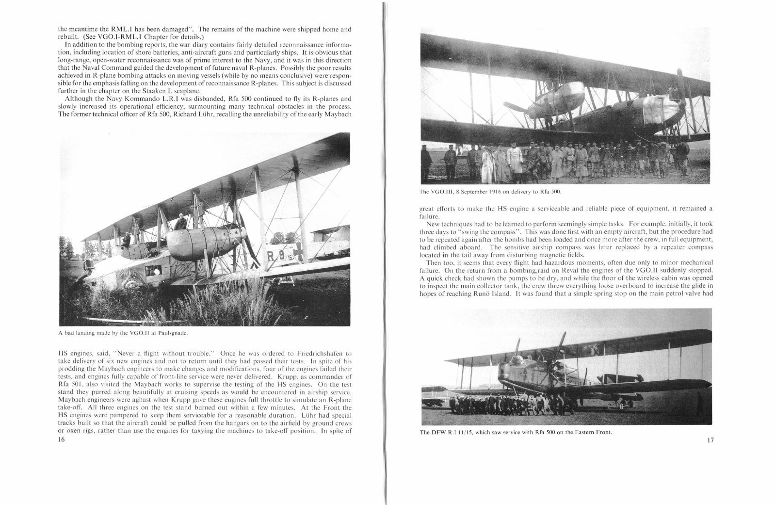
The RML.l as used on operations over the Eastern Front.
Consequently, the rebuilt RM L.I (YGO.I) wa flown to Alt-Auz by avy personnel under the commandof Lt. z. See Ferdinand Rasch. 2 The war diary, a valuable fragment of early R-plane history, providesan interesting account of what an early R-plane mission was like and illu trates the type of problemsencountered during service evaluation of the new weapon. Although the exact date of arrival of theRML.I on the Eastern Front is not known, it is pre umed that its operational life coincided with thetime span of the war diary, which ran from 12 August to 24 August 1916.
Flight Report No. I, stated that a joint attack by both R-planes (Army and avy) was scheduledfor 12 August, but was postponed because of heavy ground fog. On Sunday, 13 August, both aircrafttook off at 19.15 hours to raid the railroad junction at Schlok. The RM L.I approached a thick cloudbank north of Alt-Auz which it could not urmount. It had already taken one full hour to climb to1400 metres because the nose engine, leaking water, was incapable of supplying full power. Thecommander decided to return to the base. leaving the YGO.II to fly on alone. After landing, itwas found that a cylinder and piston head had cracked; repairs were completed by 19.00 hours on14 August, when the RM L.I was reported ready for operational duty again.
On 15 August orders were received to attack Runo, a small island in the Gulf of Riga, in orderto divert attention from a German seaplane tender which was to anchor there during the night.Rasch, the commander of the RM L.I, decided to combine this maiden attack with a raid on Schlok.The RM L.I was loaded with 500 kg. of bombs consisting of 6 ;< 50 kg. (Karbonit type). 8 X 20 kg.
1 Contrary to what has been reported in Riesellf!lIg::ellge by Offermann, the VGO.III did not perform the firstR-plane raid, since it did not join Rfa 500 until 8 September 1916.
2 Lt. Rasch later became a director of the Zeppelin-Wcrke in charge of the R-plane department.
12
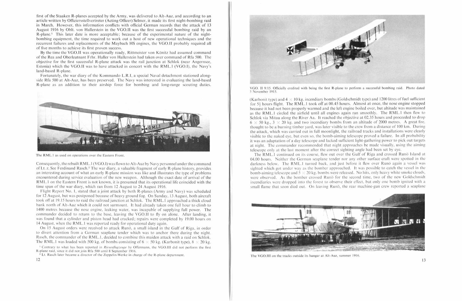
VGO. II 9/15. Officially credited with being the first R-plane to perform a successful bombing raid. Photo dated5 ovcmber 1915.
(Karbonit type) and 4 x 10 kg. incendiary bam bs (Goldschmidt type) and 1200 litres of fuel sufficientfor 5i hours flight. The RM L.l took off at 00.45 hours. Almost at once, the nose engine stoppedbecause it had not been properly warmed and the left engine boiled over, but altitude was maintainedas the RM L.t circled the airfield until all engines again ran smoothly. The RML.t then flew toSchlok via M itau along the River Aa. It reached the objective at 02.35 hours and proceeded to drop6 X 50 kg., 3 X 20 kg. and two incendiary bombs from an altitude of 2000 metre. A great fire.thought to be a burning timber yard, was later visible to the crew from a di tance of 100 km. Duringthe attack, which was carried out in full moonlight, the railroad tracks and installations were clearlyvi ible to the naked eye, but even so, the bomb-aiming telescope proved a failure. In all probabilityit was an adaptation of a day telescope and lacked sufficient light-gathering power to pick out targetsat night. The commander recommended that night approaches be made visually, using the aimingtelescope only at the last moment after the correct sighting angle had been set by eye.
The RML.l continued on its course, flew out over the Gulf of Riga and crossed Runo Island at04.00 hours. either the German seaplane tender nor any other surface craft were potted in thedarkness below. The RML.I turned back, and just before it flew over Runo again a vessel wassighted which got under way a the bomber approached. It was possible to catch the vessel in thebomb-aiming telescope and 5 x 20 kg. bombs were released. No hits, only heavy white moke clouds,were ob erved. As the bomber crossed Runo for the second time, two of the new Goldschmidtincendiaries were dropped into the forest to observe their efTcct, but only one bomb ignited with asmall flame that soon died out. On leaving Runo, the rear machine-gun crew reported a seaplane
The VGO.III on the tracks outside its hangar at Alt-Auz, summer 1916.
13

taking-off, but it quickly disappeared from sight. The first front flight of the RML. Lwas completedwhen it landed at Alt-Auz at 05.20 hour .
Flight Report No.2, dated 16 Augu t, stated that the objective for the second raid was to be theRussian seaplane base at Lebara, a round trip of 360 km. For the raid, the RML.l was loaded with3 x 50 kg., 18 x 20 kg. and 6 X 10 kg. incendiary bombs and 1100 litres of fuel. At 01.30 hoursthe bomber took-off in full moonlight, and by 03.30 hours it had gained an altitude of 2400 metres.As the bomber flew along the coast it wa spotted against the dawning north-east sky and was firedon by Rus ian land-based and shipboard anti-aircraft gun. The commander had to make the choiceof whether to swing out to sea, turn around and attack from the north-ea t, or to turn inland andapproach the coa t from a dark south-east kyo The disadvantage of the south-east approach wasthat it would give Russian aircraft ample time to climb and make contact with the RML. L after ithad turned and was recrossing the coast on its homeward flight. The commander decided to attackfrom the north-east. Although he ran the risk of being spotted by the anti-aircraft batteries againstthe light sky, this was the homeward course, and Russian aircraft would have little chance of catchingthe RML.1.
The RML.I and the VGO.[( on the airfield at Alt-Auz.
As the RM L. Lcro ed the coast from the north-east the blacked-out Lebara seaplane station couldnot be located, but everal bombs were dropped in the vicinity, and here the RML.1 was again firedon by anti-aircraft guns. A few ships were sighted along the coa t, among them two destroyers, andit was decided to attack these. At the same time four Russian seaplanes were spotted taking-off, twoof which followed the RML.l. The destroyers were engaged in a half-hour running battle, and theRML. L proved manoeuvrable enough to follow the vessels' evasive zig-zags and circles. Of thetwenty-one bombs dropped no hits were recorded, although several bombs fell directly into thewake of the destroyer. During this attack one Russian seaplane had gained sufficient altitude tofire at the RML.1 from about 300 metres below, but it was driven off by defensive machine-gun fire.The RML. L landed at 06.20 hours with shrapnel holes in the left upper wing and machine-gun hitsin the nose engine exhaust manifold, the right upper wing and the elevator.
The aircraft commander made several comments based on this raid: (I) the anti-aircraft shellsgenerally exploded well below the aircraft. Apparently the anti-aircraft crews incorrectly estimated thealtitude of the RM L. L because of its great size; (2) successful night attacks are only feasible if thelocation of the target can be exactly pre-determined either from previous visual reconnaissance, airphotographs or detailed charts; (3) the bomb-aiming telescope in its present form is inadequate fornight attacks; (4) light sky and horizon should be avoided; (5) surpri e night attacks on anchoredship are feasible, and (6) a bomb hit on a moving ve sel is purely a matter of luck.
Flight Report O. 3, dated 17 August, listed the targets as the Russian air station on Runo andthe troop encampment at Kemmern. The total flying distance wa 330 km., of which 170 km. wasover the water. The bomb load comprised 23 X 12 kg., 12 X 20 kg. and 17 X 7·3 kg. incendiary(Gold chmidt) bombs for a total of 640 kg., and 1050 litres of fuel (750 kg.) were carried for themis ion. The take-off was at 01.22 hours on a clear and moonlit night, and by 02.40 hours theRM L.l had attained a height of 1900 metres. Over Kemmern the seventeen incendiary bombs were14
The last landing of the RML.l on the Eastern Front.
released, starting minor fires that were soon extinguished except for two which burned for twentyminutes. (Here in the war diary a aval archivist had placed a short memorandum written by astafl- officer who a ked if an incendiary bomb having greater potency could be obtained.) TheRML. L flew on to Runo, where it was fired on by three moving ship. According to the report oneve sel had a searchlight, but it failed to locate the aircraft. One wonders what the gunners werefiring at if the searchlight crews could not locate the aircraft. In spite of the aircraft commander'sprevious conclusion that bomb hits on moving ships were a matter of luck, two of the ships weresighted in the bomb-aiming telescope and attacked with 20 X 12 kg. bombs from 2400 metres altitude.It was impossible to differentiate bomb hits (if any) from the gun flashes and searchlight beam, oneof which finally caught the RML.1. Russian anti-aircraft shells still exploded well below the aircraft. A second attack was made on the ships with the remaining bombs and with several bursts ofmachine-gun fire. The air station at Runo was not attacked; pre umably it could not be located inthe dark. The RML.l landed at 05.50 hours with three shrapnel holes in its wings.
Rasch, the commander, made several additional recommendations and notations: (I) silencing ofengines is strongly urged; (2) it is not as easy to evade searchlight and anti-aircraft fire with a giantaircraft as it is with smaller machines; and (3) spotting bomb hits on darkened ship at night isinconclusive because of the difficulty in differentiating among hits, earchlights and gun flashes.
Flight Report 0.4 describe the la t operational flight of the RML. Lon 24 August 1916. Thetarget, the troop encampment at Kemmern, wa to be bombed with 2 L X 20 kg., 32 X 12 kg. and9 X 10 kg. incendiary bombs; the total load of 894 kg. was the heaviest bomb load carried by theRM L.1. The 160-km. flight required 700 litres oUuel (500 kg.). The weather was 1 to ~ overcastwith slight winds, and lightning flashes were to be seen in the di tance. The unfavourable weatherdid not permit a bombing mission of greater range that night. The RML.l took-off at 03.30 hours.but once in the air the port engine began to boil and continued to do so even at reduced throttle.The flight was cancelled and the machine landed at 04.30 hours. The RML.l was reported ready againfor operational duty on 25 Augu t. This wa the last entry in the RM L.l war diary. The war diary ofthe Kommando L.R.1. ended followed by a short telegram dated I September 1916 stating that "in
15
the meantime the RML.l has been damaged". The remains of the machine were shipped home andrebuilt. (See VGO.l-RML.l Chapter for details.)
In addition to the bombing reports, the war diary contains fairly detailed reconnaissance information, including location of shore batteries, anti-aircraft guns and particularly ships. It is obvious thatlong-range, open-water reconnaissance was of prime interest to the Navy, and it was in this directionthat the Naval Command guided the development of future naval R-planes. Possibly the poor resultsachieved in R-plane bombing attacks on moving vessels (while by no means conclusive) were responsible for the emphasis fall ing on the development of reconnaissance R-planes. This su bject is discussedfurther in the chapter on the Staaken L seaplane.
Although the Navy Kommando L.R.! was disbanded, Rfa 500 continued to fly its R-planes andslowly increased its operational efficiency, surmounting many technical obstacles in the process.The former technical officer ofRfa 500, Richard LLihr, recalling the unreliability of the early Maybach
A bad landing made by the VGO.II at Paulsgnade.
HS engines, said," ever a flight without trouble." Once he was ordered to Friedrichshafen totake delivery of six new engines and not to return until they had passed their tests. In spite of hisprodding the Maybach engineers to make changes and modifications, four of the engines failed theirtests, and engines fully capable of front-line service were never delivered. Krupp, as commander ofRfa 501, also visited the Maybach works to supervise the testing of the HS engines. On the teststand they purred along beautifully at cruising speeds as would be encountered in airship service.Maybach engineers were aghast when Krupp gave these engines full throttle to simulate an R-planetake-off. All three engines on the test stand burned out within a few minutes. At the Front theHS engines were pampered to keep them serviceable for a reasonable duration. Li.ihr had specialtracks built so that the aircraft could be pulled from the hangars on to the airfield by ground crewsor oxen rigs, rather than use the engines for taxying the machines to take-off position. Tn spite of
16
The VGO.III, 8 September 1916 on delivery to Rfa 500.
great efforts to make the HS engine a serviceable and reliable piece of equipment, it remained afailure.
New techniques had to be learned to perform seemingly simple tasks. For example, initially, it tookthree days to "swing the compass". This was done first with an empty aircraft, but the procedure hadto be repeated again after the bombs had been loaded and once more after the crew, in full equipment,had climbed aboard. The sensitive airship compass was later replaced by a repeater compasslocated in the tail away from disturbing magnetic fields.
Then too, it seems that every flight had hazardous moments, often due only to minor mechanicalfailure. On the return from a bombing,raid on Reval the engines of the VGOJI suddenly stopped.A quick check had shown the pumps to be dry, and while the floor of the wireless cabin was openedto inspect the main collector tank, the crew threw everything loose overboard to increase the glide inhopes of reaching Runo Island. It was found that a simple spring stop on the main petrol valve had
The DFW R.t 11/15, which saw service with Rfa 500 on the Eastern Front.
17

broken, allowing the vibration to slowly turn and seat the valve. At about 400 metres, with units ofthe Russian Fleet below, the engines fired up and the crew of the VGO.lI escaped capture. Anothertime the wiring in the wireless cabin caught fire but was swiftly checked with a hand extinguisher.Continual close-calls such as these made the crews uneasy, and they did not relish flying these early,unreliable machines. With time they often became nervous and touchy. It has been said that on vonHallerstein' last flight in an R-plane he was so nervous that he fought the controls and was unableto control the machine by him elf. The early R-planes were not easy to fly; on the contrary, it washard work for one man. During periods of gusty summer weather pilots would often discard theirflying-coats and helmets and fly missions wearing just their ordinary jackets open at the neck. "Wesweated like bulls" wa how Li.ihr aptly described it. Two complete turns of the steering-wheel wererequired to operate the ailerons (VGO.ll), and flying was a continual struggle to counteract the movements of the aircraft in the air.
Staaken R.l V 12/15. The only R-plane to see action on both the Eastern and Western Fronts. Late style markingson be seen pamted over the old Patee crosses which still faintly show through.
As experience was gathered and confidence gained, the two R-plane quadrons began to have aneffect on the course of the war. For example, in one attack by Rfa 500, the VGO.lI and VGO.11lde troyed the switch-points at the railway yards at Rodenpois and delayed the departure of the Firstand Second Siberian Corps to Galicia for a crucial 18 hours. The importance of this and otherattacks by Rfa 500 and 501 was not lost on the High Command, and certainly contributed to thelaunching of the large R-plane construction programme of 1916.
Information regarding the activities of Rfa 500 during 1917 is very incomplete. Its commandervon Hallerstein was killed flying the experimental Dornier V.l fighter at Friedrichshafen on 13November 1916. The next known commander of Rfa 500 was Hauptmann Erich Schilling, who ledthe squadron on the Western Front until his fatal crash in the R.52 on 12 August 1918. Aircraft18
Staaken R.IV 12/15, here seen at Alt-Auz early in its long operational career.
known to have been assigned to Rfa 500 on the Eastern Front were the VGO.H, VGO.lII (crashed24 January 1917), DFW R.I (cra hed September 1917) and the Staaken R.IV. The DFW R.I flewonly a single bombing mission on 13 June 1917, during which it dropped 680 kg. bomb on Schlokin retaliation for an earlier Russian raid. On 29 June 1917 the Staaken R.lV attacked the railroadtation at Wolmar located on the Riga-St. Petersburg line with 1500 kg. bombs during a four-hour
mission. Good results were observed. An excerpted combat report of it second mission on 9 July1917 has been found and reads a follows:
Objective: Bombing attack by R. 12/15 on the heavy coastal batter, munition dumps andtroop encampments at Zerel (Oesel Island).
Cre\\': Two officer pilots, one officer observer, one master mechanic, two gunners andone wireless operator.
Load: Machine guns and ammunition 254 kg.15 X 50 kg. and 60 X 12·5 kg. bomb 1500 kg.Other 2552 kg.Useful Load 4306 kg.Loaded weight 14,050 kg.
Duration: Start, 00.07 hrs. Landing, 03.55 hrs.Time 3 hrs. 48 mins.
Route: Alt-Auz-Talssen-Dondangen-Zerel and back (380 km.).Highest Altitude: 3200 m.Action Report: Take-off was made with flare illumination, landing in the early dawn
without illumination. The flight was performed on instruments and compa s. The Drexlergyro bank-indicator operated perfectly. During the flight, wind measurements werereceived on the wireless. Since the target lay on the coast which was delineated by thebeach, the bomb-aiming tele cope could be used with outstanding success.
The R.12 reached the target at 02.00 hrs. and circled for 20 minutes. Most of the bombs appearedto hit the target. One large explosion forming a huge smoke cloud was observed. Russian antiaircraft fire from both land and ships was inaccurate, no searchlights or enemy aircraft were seen.An Albatros C. VJ( accompanied the R.12. During the bombing it attacked the enemy anti-aircraftpositions, thereby diverting attention from the R.12.
Rfa 500 probably left Alt-Auz in late 1917 and returned to Dbberitz to re-equip and train with
19

the new Staaken R.Yl machines. It was transferred to Custinne (France) in February 1918, and theactivities of Rfa 500 on the Western Front are de cribed in that section.
After the SSW R.l had been shipped home, Krupp, in anticipation of new SSW R-planes arrivingat the front, began to prepare for the extensive facilities that he knew would be required. He founda suitable airfield and barrack at Porubanok, a former military isolation ho pital outside Vilna. L
Large steel framework hangars were erected and facilities were put in readiness for the SSW R. 6.which arrived on 7 August 1916. Just prior to this date, on 3 Augu t 1916, Rfa 501 was officiallyformed under the command of Obit. Krupp and executed its first bombing mission on 3 SeptemberJ916, when the R.6 bombed Molodeczne in daytime accompanied by two escort machines. After thesecond daylight attack, further operations had to be performed under the cover of darknes due tothe Jow operational altitude of the aircraft, which exposed it to severe Ru sian ground fire. This.in turn, required the development of entirely new night navigation techniques based on searchlightsignals and coloured rockets fired at regular intervals.
Rfa 501 wa commanded by Obit. Krupp until November 1916, when Hptm. Richard von Bentivegni took over the command for the remainder of the war. During its service on the EasternFront, Rfa 501 was attached to the German 10th Army; it was equipped exclusively with SSWR-planes, and its operational strength consisted of one to three R-planes and a number of escortaircraft. 2 The SSW bombers were active against Russian target, but the exaet number of missions
SSW R.IV 4/15, on the occasion of an inspection of Rfa 501 by General von Oven at Lyntupy.
flown is unknown. (For list of know/l raids which were flown by Rfa Salon the Eastern Front seeAppendix 4.)
The few existing combat reports of Rfa 501 and the correspondence between the squadrons andthe manufacturers are filled with descriptions of technical and tactical problems that requiredsolution before the R-plane could be considered ready for service on the Western Front. Taken oneat a time, these difficulties may appear minor, but as a group they made a formidable list.
An excerpt from the combat report of the raid on Wileyka illustrates some of the difficultiesencountered, in this in tance, during a night mi ion. The report tates that the engine noise of theR.5 was audible from a great distance and that the machine could be located in the dark; approachinghead-on at 600 metres altitude, the glowing exhaust manifolds in ide the engine-room were clearlyvisible, and as the R.5 flew overhead the fu elage was illuminated by the red-hot exhaust pipes that
J row Vilnius in Lithuania.2 Delivery dates of the SSW R-planes to Rfa 501 were:
SSW R.6 7 August 1916SSW R.5 4 September j 916SSW R.7 February/March 1917SSW R.4 April 1917
20
ran alongside. Sparks issuing from the exhaust enabled observers to follow the machine Jong afterit had disappeared in the darkne . This, the report continues, explained why the Ru ian troopswere able to pot the R.5 from a di tance and subject it to accurate anti-aircraft fire at night. Thereport recommended sealing the engine-room windows and in tailing spark catchers.
Other problems exposed by the service tests of the SSW R-planes covered a broad spectrum.For example, the bank indicator was not sensitive enough, making it difficult to read under nightflying conditions; continual vibration cau ed Jight bulbs to fail; engine-room thermocouples read15° C lower than those in the pilot' cabin, and the noise of the engines hampered communicationbetween the pilots and mechanic, necessitating the field installation of an optical engine-telegraph.
Sometimes an oversight was responsible for a chain reaction of failures. Since the radiator ofthe R.5 had not been insulated, it vent pipes had frozen during a long winter flight. This preventedsteam from escaping, and the pressure burst the radiator. The lack of water caused the enginecylinders to glow red-hot, melting the compression cocks and the metallic gaskets. The engine wasstopped and the R.5 reached its airfield safely on two engine (7 January J9J7). It was found expedientto replace the burnt-out engine by one originally intended for the R.6, but its gear-box flange was ofdifferent size. The report of this incident ended with a plea for the interchangeability of parts.
Problems such as the above were typical of those encountered and solved by the personnel of theR-plane quadrons. Although the aircraft were perhaps barely suited for combat service, their earlydeployment revealed shortcomings which would have otherwise remained unexposed. Without suchfront-line experience, the development of more reliable and powerful R-planes could not have beenpossible.
The following Rfa 501 combat report, translated and presented in the format of the original,describes a typical combat mi sion and the type of information which wa reported to Rea fortransmittal to the R-plane manufacturers.
SSW R.VII 7/15, in service with Rfa 501 against the Russians during 1917.
21

R.5 ACTION REPORT
Start: The windows were left open during the take-off because it was necessary to startagainst the sun. At 400 metres the windows were closed and an increase of speed was noted .While flying through clouds the windows had to be reopened and remained so until landing.The window-frames greatly hindered the pilots' view of the terrain during the long time theR.5 flew at 200 metres. The Cellon canopy needs to be rebuilt as soon as the ncccssarymaterial arrives.
Engines: Faultless.Gearbox: After Ii hours the starboard engine clutch ran so hot that sparks shot out, in
spite of having disengaged the leather-cone friction clutch five minutes after take-off. 1
Engine Cooling: Faultless.Controls: The rudder is too small. ]t was not possible to turn the machine into the wind
with the rudder control alone; to do so required a combination of elevator and ruddercontrol.
1nstruments: The temperature indicator in the pilots' cabin did not function. The reasonfor failure has not yet been determined. With well-trained mechanics a single temperatureindicator in the engine-room is deemed adequate.
Better communication between pilots and mechanic is desired. An optical engine telegraph is being constructed. The compass and inclinometer are satisfactory.
Bomb-release Mechanism: The electrical release mechanism of the main bomb containerdid not operate satisfactorily. Two bombs remained hanging and were released only afterseveral attempts. The mechanical release of the P.u.W. bomb container was triggered bythe mechanic on signal from the bomb-officer (commander) and operated perfectly. Thechoice of bombs must remain the prerogative of the commander, therefore the designersshould attempt to install interchangeable bomb fittings. The bombing of troop encampments is without doubt more effective with fifty light, instead of ten heavy bombs.
Armament: With a crew of four, as is now customary, the armament is hardly more thana useless load. The mechanic is too busy in the engine-room to man the machine-gun atthe proper moment during an air battle. At this critical time the commander would bestationed in the nose and would not be able to reach his machine-gun in the dorsal turret.It is impractical to mount a machine-gun in the nose using the presently available MG-pivotbecause the pivot can not be properly secured to the fuselage. Even if an improved pivotwere provided, a nose machine-gun would have a limited field offire due to the constructionof the fuselage. Finally, all of our pivots prevent training the machine-gun quickly in astrong slip-stream. This shortcoming will exist until the pivot is replaced by the provengun-ring of a C-type aircraft.
Navigation: The aircraft headed for the Wischniew Lake at 100 metres altitude aftermaking a wide circle around the airfield. Using the ground as reference, the drift wasestimated at 10° and the speed at 150 km.h. At about 12.15 hours, the trenches along theWischniew Lake were crossed at 2100 metres. The forward Russian trenches were clearlyseen, but farther east a heavy cloud layer was sighted. After setting course for Iza, the
1 The SSW clutch consisted of a conical leather-faced friction clutch and a centrifugal key clutch. This compoundclutch was a constant source of trouble and not until it was modified and inspected after every flight was the reliabilityproblem partially solved. (See SSW chapter for details.)
C 23
Flying Time: R.5: Take-off Il.I5 hI'S., Landing 14.00 hI'S. (2* hI'S.)R.6: Take-off 11.20 hI'S., Landing 11.28 hI'S. (8 mins.)
Route: R.4: Yilna-Wischniew Lake-Swir-Korkocyzyski-YilnaR.6: Circuit of airfield
Attained Altitude:
REPORT OF THE R.5 WAR FLIGHT ON 26 NOVEMBER 1916Preparations: SSW R.6 had been standing-by for operational orders since its last flight
on 15 November. The coupling defect which appeared on the last flight of the R.5 wasrepaired and the machine was ready for operational duty on 20 November, but it was notpossible to perform a test flight until early morning of 26 November. Taking advantagefor the first partially clear weather in a long while, both R-planes and the escort aircraftwere prepared for a bombing mission. The weather and wind report which had beendelivered earlier showed strong south-south-west winds and increasing cloud cover withrain to follow. At 10.30 hours a new weather report was requested which would take anhour to reach the squadron. Rather than lose the momentary opportunity to fly, the take-offwas ordered for 11.00 hours.
•
The SSW R. V 5/15, which flew operationally with Rfa 501 at Vilna.
A rack for eleven 12·5 kg. P.u.W. bombs had been installed underneath the fuselage ofthe R.5. in order to drop a greater number of bombs on the troop encampment. The twosupplementary bomb containers, each with a capacity of 5 P.u.W. bombs which had beeninstalled at an earlier date behind the main bomb container, were removed. The weight ofthese supplementary bomb containers installed far behind the centre of gravity had madethe R.5 very tail-heavy. For the intended raid the armament was increased to two machineguns (one in the upper turret and one in the wireless position, shooting downwards) becauseonly one escort aircraft was available.
Mission: to bomb the troop encampment at Iza (mission chosen at the discretion ofHptm. von Bentivegni, commander of Rfa 501).
Weather: Wind SSW, 16 to 20R.5 Crel\'.' Pilots: Lt. von Seydlitz-Gerstenberg
Offz. Stellv. Buth 1
Commander: Hptm. von BentivegniMechanic: Gefreiter Schroder
R.6 Crt' I l'.' Pilots: Offz. Stellv. HebartYizefeldwebel Arnold
Commander: Obit. BorchersMechanic: Gefreiter Waldeck
IOn 29 March 1918 Buth was awarded the Goldene Militar Verdienst Kreuz, the non-commissioned officer'sPour Ie Merite. Buth \\as killed in the crash of the R.43 on II August 1918.
22
R.5R.6
1000 m.19 min.
300 m.j5 min.
1500 m.32 min.
2000111.54 min.
2150 m.69 min.

24
bomb-officer (commander) went to the nose to search for a troop encampment through thecloud-cover. Bombs were released, but unfortunately the bomb bursts could not be seen.During the bombing run the aircraft had to turn and the bomb-officer lost his orientationbecause the terrain was covered by clouds and the nose position was not provided with acompass. The aircraft headed north towards an opening in the cloud layer and Rew onuntil a rain-cloud formation was encountered. Here we went down to 250 metres. Thestrong gu ts almost prevented us from maintaining course. After a short time we spottedthe railroad tracks (Di.inaburg-Vilna) near Korkoczyski andAew along them. The threequarter hour Aight at 250 metres proved that the SSW R-plane can be Aown in strong gustyweather.
Landing: Touch-down was smooth, but during the landing run the right front tyre burst.
Prince Leopold IV of Lippe leaving a SSW R-plane during a visit to Rfa 501 at Porubanok, summer 1916.
R.6 ACTION REPORT
Start: The take-off followed the R.5 by 5 minutes, also with opened windows. At 300metres a compression cock started to leak, forcing the R.6 to land. While replacing thecock, a new unfavourable weather report was received, and the commander decided tocancel the Right. In the future, mechanics will carry spare compression cocks on Rights.
ESCORT AIRCRAFT-Albatross CIII 4077/15
Started 20 minutes later than the R.5 and remained in the immediate vicinity approximately 400-500 metres above us during the entire Aight.
LESSONS LEARNED AND RECOMMENDATIONS
Technical: It was established after landing that the thrust ball bearing of the starboardclutch had seized and disintegrated. The causes for failure are twofold: the bearing ismuch too light; nor is it properly lubricated. The fact that this particular incident hasoccurred twice previously in the R.5 is enough evidence to prove that the strength of thethrust bearing is insufficient for this purpose.
Because the repair will require about three weeks, an attempt will be made to disengagethe leather-cone friction clutch immediately after the engines have been started and to flywithout using the thrust bearing.
Instruments: The red and green lights used for signalling to the pilots from the uppercommander's position (upper turret) have been very successful.
Meteorology: Under the local operational conditions the military weather reportingservice becomes a decisive factor in the success of an R-plane squadron. The local weatherchanges so rapidly and to such a great degree that, in addition to front-line weather reportingstations, a suitable weather station must be established at the airfield. Only in this mannercan wind and weather measurements be obtained promptly before the start of a mission.
Signed: ron Bentiregl/i
These combat reports and incidents amply illustrate the variety of problems encountered by Rfa500, Rfa 50 I and Kommando L. R.I d uri ng thei I' fi rst mon ths of operational service. There is noquestion that the officers, crew and engineers of the Rfas energetically solved many of the complexissues that confronted them and set the stage for R-plane operations on the Western Front. It is onlynecessary to compare these early combat reports with one written later in the war to see what progresshad been made at all levels. The matter-of-fact attitude of the Rfa 50 I combat report of 24/25 August1918 (see page 42), is evidence that much had been accomplished in a mere twenty months.
Rfa 501 continued its activity on the Eastern Front until June or July 1917, at which time it wastransferred to Berlin (Dbberitz and Staaken) to train with the new Staaken R.V! bombers. Vilnabecame the base for an R-Schulabteilung (R-Training Section), which used SSW R-planes convertedto trainers.
This photograph shows the SSW R.7 crashed at Vilna.
The SSW RA and R.7 were assigned to R-Schulabteilung Vilna and the SSW R.I, R.2 andR.3 were assigned to the Rea at D6beritz as trainers. Vilna remained a training base until 22June 1918 at which time personnel were moved to the Rea Cologne which had been previouslyestablished to provide a support and training facility close to the Western Front. Two destroyedR-planes were found there by Allied troops at war's end.
R-PLANE RAIDS ON ENGLA D
During the time the R-plane squadrons were gathering operational experience on the EasternFront the airship service had suffered staggering losses from which it never really reco\lered. TheGerman Navy, on the one hand, continued to fight defeat under the energetic leadership of Korvettenkapit~in Strasser, head of the Naval Airship Service, and his supporter Admiral Scheer; however,subsequent raids, even with improved airships Aying at even-higher altitudes, proved to be ineffective.As a matter of record, London was bombed by naval airships only once after 1916, and this was a
25

ca e of pure luck; the airship was accidentally blown over London by high winds.1 On the otherhand, the Army, having G-type bombers and R-planes to fall back on, disbanded its Airship Serviceafter the L.Z.I07 executed the last Army raid on 16 February 1917. Incidentally, many of the airshipcrews were tran ferred to the R-plane squadrons, particularly the engine mechanics whose knowledgeof the Maybach engine was found very useful.
In the autumn of 1916 Generalleutnant von Hoeppner, the Kommandierende General der Luftstreitkrafte (Kogenluft-Commanding General of the Air Forces) issued a memorandum stating thatairship attacks on London had become hopeless and that the task of bombing the city would soonbe assigned to the Fliegertruppe (Aviation Troops). The campaign against London was to rely ontwo new weapons: the G-type bombers of the Bombengeschwader (Bombing Squadrons) and theR-planes of the Rfas. n analysis of the total orders placed for R-planes shows that roughly onehalf were ordered in 1916. The demise of the airship and the desire to continue large-scale attacksagainst London with heavy bomb loads were undoubtedly two of the factors behind the large R-planeconstruction programme of 1916.
Unfortunately document concerning the exact nature of the military and strategical considerationswhich guided policy planners are not available. They would be of particular interest in the light ofGermany's bomber policy in World War If.
Originally the London raids were to have begun in the spring of 1915; they were postponed untilthe spring of 1916, but plans again miscarried due to lack of proper equipment. By the time theKogenluft memorandum was written (autumn 1916), the Gotha G.IY, an aircraft capable of bombingLondon, had been developed and the R-plane was considered to be "ready within a short time" tojoin the England squadrons. This last statement ring the bell of optimism so traditional in militaryplanning documents. In fact, virtually a year was to pass before the R-plane made its appearance inEnglish skies.
The London raids were considered by General Ludendorff (Chief of Staff of Field MarshalHindenburg) to be primarily a strategic propaganda weapon. In his book Kriegfriihrung und Politik.Ludendorff described the political situation in the spring of 1917, shortly before the beginning of theLondon raids:
I n the meantime, a compelling necessity had become manifest: to reinforce, through a largescale increase in propaganda, the purely military conduct of the war and the unrestrictedsubmarine campaign by an attack against the spirit of the enemy populace and its militaryforces. To assure final victory, it purpose wa to shatter the unity of the enemy and dispeltheir belief in victory.
Major Frhr. yon BLilow, the historian who analysed the London raids from the German point ofview. wrote:
The main purpose of the bombing attacks was the intimidation of the morale of theEnglish people, the crippling of their will to fight and the preparation of a basis for peace.The secondary purpose of the raids was to disrupt the British war industry, disorganizethe communication between coastal ports and London, attack supply dumps of coastalports and hinder transport of war materials across the Channel. The target of the raids wasconfined principally to London because it wa the heart of England, the operational headquarters of the Allie and the centre of its war industry.
The Kogenluft memorandum was accepted by the High Command and secret preparations for thegreat London raids were authorized to begin under the code name "TLirkenkreuz" (Turk's Cross).The plans called for Bombengeschwader 3 to be operationally ready by February 1917, but delaysin completing the required number of G-type bombers, difficulties in securing raw materials andfailure of production aircraft to meet acceptance standards all combined to postpone the date ofthe first raid until the middle of May.
From 25 May to 22 August 1917 the Gotha bombers raided England in full daylight in groups ofabout twenty aircraft per raid. Day-bomber losses soon became intolerable. British defences had
1 Known as the "Silent Raid" by airship LAS on 19 October 1917.
26
considerably stiffened since the first raids, and the slow speed and low attack altitude prevented theGothas from evading ever-improving British air and ground defences. In order to continue theLondon raids, the German High Command was forced to change over to night attacks, the first ofwhich took place on 3 September 1917. The shift to night missions coincided with the arrival ofRfa 501 in Belgium almost a year behind the Kogenluft schedule. In August 1917 Rfa 501 wastransferred from Berlin to Belgium and stationed in the Ghent area. The main airfield of Rfa 501was Scheldewindeke, which was equipped with a specially-constructed concrete apron. Other fieldsused generally in an emergency were St. Denis-Westrem, Gontrode and Ghistelles near Ostend.
The decision by the High Command to attack England by night fitted the e tablished pattern ofR-plane operations. On the Eastern Front the crew had learned how to fly at night, and the problemof navigation and target location had been partially solved by an early form of radio triangulation.Also an extensive network of visual navigational aids consisting of flares, rockets and searchlightshad been created to guide German aircraft through the dark skies. avigational instruments especially
Ground personnel of Rfa 500 with 100 kg. and 300 kg. P.u.W. bombs.
useful for night flying had been developed: gyro-compass, gyro-bank indicator, inclinometers andwireless equipment. The German R-planes had come a long way since early 1915, and they enteredthe Western stage of operations on a fairly high level of technological development.
A good deal has been written about the England raids Aown by Bombenge chwader 3 and Rfa 501.As might be expected, the writings of German and British historians do not agree on every detail,but the description of the part played by the R-plane is essentially consistent throughout. Appendix 6lists all the raids on England in which R-planes participated as extracted from German and Briti hsources.
For purposes of co-ordination Rfa 501 was placed under the operational control of Bombengeschwader 3, and both squadrons received their orders directly from the German High Command(Oberste Heere leitung). The aircraft assigned to Rfa 501 consisted solely ofStaaken machines (R.IY,R.Y and R.Yl).
27
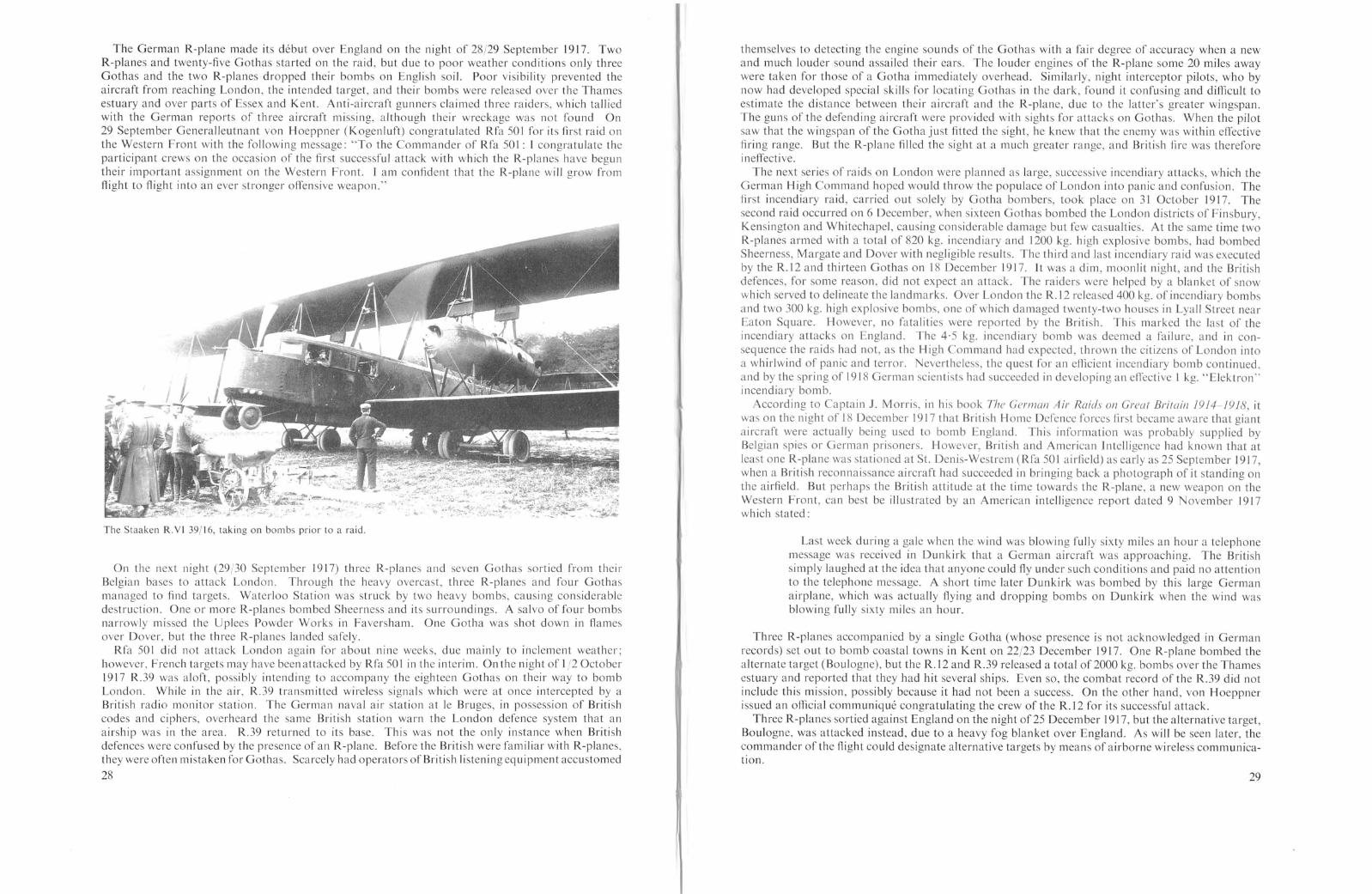
The German R-plane made its debut over England on the night of 28/29 September 1917. TwoR-planes and twenty-five Gothas started on the raid, but due to poor weather conditions only threeGothas and the two R-planes dropped their bombs on English soil. Poor visibility prevented theaircraft from reaching London, the intended target, and their bombs were released over the Thamesestuary and over parts of Essex and Kent. Anti-aircraft gunners claimed three raiders, which talliedwith the German reports of three aircraft missing, although their wreckage was not found On29 September Generalleutnant von Hoeppner (Kogenluft) congratulated Rfa 501 for its first raid onthe Western Front with the following message: "To the Commander of Rfa 501: I congratulate theparticipant crews on the occasion of the first successful attack with which the R-planes have beguntheir important assignment on the Western Front. I am confident that the R-plane will grow fromflight to flight into an ever stronger offensive weapon."
The Staaken R.YI 39/16, taking on bombs prior to a raid.
On the next night (29/30 September 19 L7) three R-planes and seven Gothas sortied from theirBelgian bases to attack London. Through the heavy overcast, three R-planes and four Gothasmanaged to find targets. Waterloo Station was struck by two heavy bombs, causing considerabledestruction. One or more R-planes bombed Sheerness and its surroundings. A salvo of four bombsnarrowly missed the Uplees Powder Works in Faversham. One Gotha was shot down in flamesover Dover, but the three R-planes landed safely.
Rfa 501 did not attack London again for about nine weeks, due mainly to inclement weather;however, French targets may have been attacked by Rfa SO I in the interim. On the night of 1/2 October1917 R.39 was aloft, possibly intending to accompany the eighteen Gothas on their way to bombLondon. While in the air, R.39 transmitted wireless signals which were at once intercepted by aBritish radio monitor station. The German naval air station at Ie Bruges, in possession of Britishcodes and ciphers, overheard the same British station warn the London defence system that anairship was in the area. R.39 returned to its base. This was not the only instance when Britishdefences were confused by the presence of an R-plane. Before the British were familiar with R-planes,they were often mistaken for Gothas. Scarcely had operators of British listening eq uipment accustomed
28
themselves to detecting the engine sounds of the Gothas with a fair degree of accuracy when a newand much louder sound assailed their ears. The louder engines of the R-plane some 20 miles awaywere taken for those of a Gotha immediately overhead. Similarly, night interceptor pilots, who bynow had developed special skills for locating Gothas in the dark, found it confusing and difficult toestimate the distance between their aircraft and the R-plane, due to the latter's greater wingspan.The guns of the defending aircraft were provided with sights for attacks on Gothas. When the pilotsaw that the wingspan of the Gotha just fitted the sight, he knew that the enemy was within effectivefiring range. But the R-plane filled the sight at a much greater range, and British fire was thereforeineffective.
The next series of raids on London were planned as large, successive incendiary attacks, which theGerman High Command hoped would throw the populace of London into panic and confusion. Thefirst incendiary raid, carried out solely by Gotha bombers, took place on 31 October 1917. Thesecond raid occurred on 6 December, when sixteen Gothas bombed the London districts of Finsbury,Kensington and Whitechapel, causing considerable damage but few casualties. At the same time twoR-planes armed with a totaL of 820 kg. incendiary and 1200 kg. high explosive bombs, had bombedSheerness, Margate and Dover with negligible results. The third and last incendiary raid was executedby the R.12 and thirteen Gothas on 18 December 1917. It was a dim, moonlit night, and the Britishdefences, for some reason, did not expect an attack. The raiders were helped by a blanket of snowwhich served to delineate the landmarks. Over London the R.12 released 400 kg. of incendiary bombsand two 300 kg. high explosive bombs, one of which damaged twenty-two houses in Lyall Street nearEaton Square. However, no fatalities were reported by the British. This marked the last of theincendiary attacks on England. The 4·5 kg. incendiary bomb was deemed a failure, and in consequence the raids had not, as the High Command had expected, thrown the citizens of London intoa whirlwind of panic and terror. Nevertheless, the quest for an efficient incendiary bomb continued.and by the spring of 1918 German scientists had succeeded in developing an eflective I kg. "Eleklron"incendiary bomb.
According to Captain J. Morris, in his book The German Air Raids on Greal Brilain 19J4-J918, itwas on the night of 18 December 1917 that British Home Defence forces first became aware that giantaircraft were actually being used to bomb England. This information was probably supplied byBelgian spies or German prisoners. However, British and American lntelligence had known that atleast one R-planc was stationed at St. Denis-Westrem (Rfa 501 airfield) as early as 25 September 1917,when a British reconnaissance aircraft had succeeded in bringing back a photograph of it standing onthe airfield. But perhaps the British attitude at the time towards the R-plane, a new weapon on theWestern Front, can best be illustrated by an American intelligence report dated 9 November 1917which stated:
Last week during a gale when the wind was blowing fully sixty miles an hour a telephonemessage was received in Dunkirk that a German aircraft was approaching. The Britishsimply laughed at the idea that anyone could fly under such conditions and paid no attentionto the telephone message. A short time later Dunkirk was bombed by this large Germanairplane, which was actually flying and dropping bombs on Dunkirk when the wind wasblowing fully sixty miles an hour.
Three R-planes accompanied by a single Gotha (whose presence is not acknowledged in Germanrecords) set out to bomb coastal towns in Kent on 22/23 December 1917. One R-plane bombed thealternate target (Boulogne), but the R.12 and R.39 released a total of 2000 kg. bombs over the Thamesestuary and reported that they had hit several ships. Even so, the combat record of the R.39 did notinclude this mission, possibly because it had not been a success. On the other hand, von Hoeppnerissued an official communique congratulating the crew of the R.12 for its successful attack.
Three R-planes sortied against England on the night of25 December 19L7, but the alternative target,Boulogne, was attacked instead, due to a heavy fog blanket over England. As will be seen later, thecommander of the flight could designate alternative targets by means of airborne wireless communication.
29

The R-plane was capable of putting up an effective defence because it provided a stable gunplatform and it had a good field of fire. This was demonstrated by an R-plane which accompaniedthirteen Gothas on the night of28/29 January 1918. The R-plane was intercepted on its inward flightby two patrolling aircraft of the Home Defence squadrons. One machine closed to attack, but theR-plane commander managed to disengage by adroit manoeuvring. Soon after, the giant was againintercepted by a Bristol Fighter flown by 2nd Lieutenant Goodyear of No. 39 Squadron, RoyalFlying Corps. In the sharp skirmish that followed, Lt. Goodyear's engine was put out of action andhis observer wounded. The R-plane, having dealt with the defence aircraft, turned and dropped itsbombs in central London; one of them, a 300 kg. bomb, crashed through a pavement grating outsideMessrs. Odhams Printing Works (in Long Acre), publishers of John Bull. The bomb penetrated tothe basement air-raid shelter and exploded with devastating effect, killing thirty-eight persons andinjuring ninety. The lower walls and supporting pillars of the building collapsed, bringing threeconcrete stories down on the unfortunate victims. The conflagration that followed was observed bythe R-plane's crew, who thought it was a hit near the Admiralty. After being turned from its homeward course twice by barrage fire and then being attacked by another British pilot, the R-plane flewsafely home.
On the following night (29/30 January) good weather conditions prevailed and four giants, eachcarrying a total of 1000 kg. of high explosive, started on the first of several raids without the customaryaccompaniment of Gotha bombers. One R-plane was forced to return because of engine failure. Ofthe three remaining R-planes, one was diverted from London by the anti-aircraft barrage at Billericayand dropped its bombs on Rawneth, Thundersley, Rayleigh and into the sea off the Blackwater. Thissolitary raider caused no casualites and negligible damage. Captain A. Dennis of No. 37 Squadron.flying a B.E.12, attacked the second London-bound giant. In the fierce fight that followed, the B.E.12received such a large number of hits that Captain Dennis had to retire, but not without causing thegiant to veer off-course, dropping its bombs on Isleworth, Kew and Brentford as it went. A patrollingaircraft caught this giant again near Gravesend, but after firing 100 rounds the pilot was blinded bythe flash of his own tracers and the quarry escaped. The third giant was intercepted near NorthBenfleet and vigorously attacked by four fighters, forcing the raider to prematurely drop its bombs onWanstead. The giant flew very low and according to the British was on the verge of landing when the
A Staaken R.YI in flight.
30
Odhams Printing Works, Long Acre, hit by a 300 kg. bomb on the night of 28(29 January 1918. This was the worstsingle incident caused by air raids during World War I.
fighters drew off. This was a most successful night for the British Home Defence; although it did notsucceed in shooting down any giants, it prevented them from reaching the centre of London andcaused them to drop their bom b load off target with minor results.
The overcast night of 16/17 February 1918 saw the giants over England again. The Germans hadchosen this night to drop their first 1000 kg. bomb, the largest bomb to be dropped on English soil inthe war. The dubious honour of carrying the bomb went to R.39. Of the five raiders, R.39 and R.12penetrated the London defences and the 1000 kg. bomb hit the North Pavilion of the Royal Hospital,Chelsea. Five people perished in the explosion, which caused destruction over an exceptionally widearea. The R.12 dropped two 300 kg. bombs on Woolwich, killing seven people and injuring two. Theeight 50 kg. bombs that fell at Beckenham exploded harmlessly in a park. The R.25 claimed that ithad bombed Dover with good effect, but from the British side the bombs were seen to explodeharmlessly near St. Margaret's Bay east of Dover. The R.33 was forced to drop its bombs prematurelyinto the sea at Deal because of engine failure. With three of its four engines dead and flying 200metres above the Channel, it barely reached the Belgian coast and landed safely. The exploits of thefifth raider are not known.
It was during this raid that the R.12 commanded by Obit. von Seydlitz-Gerstenberg flew into theballoon apron which was stretched between the Woolwich Works and the West India Docks. Hereis an excerpt from his combat report:
The aircraft was first pulled to starboard, then port and finally side-slipped out of controlto the port side. The first pilot, Lt. Gatte, immediately throttled-down all engines, thenopened up the throttles on only one side, whereby the aircraft regained equilibrium onceagain after having fallen 300 metres. The impact of the balloon apron was so severe that the
31
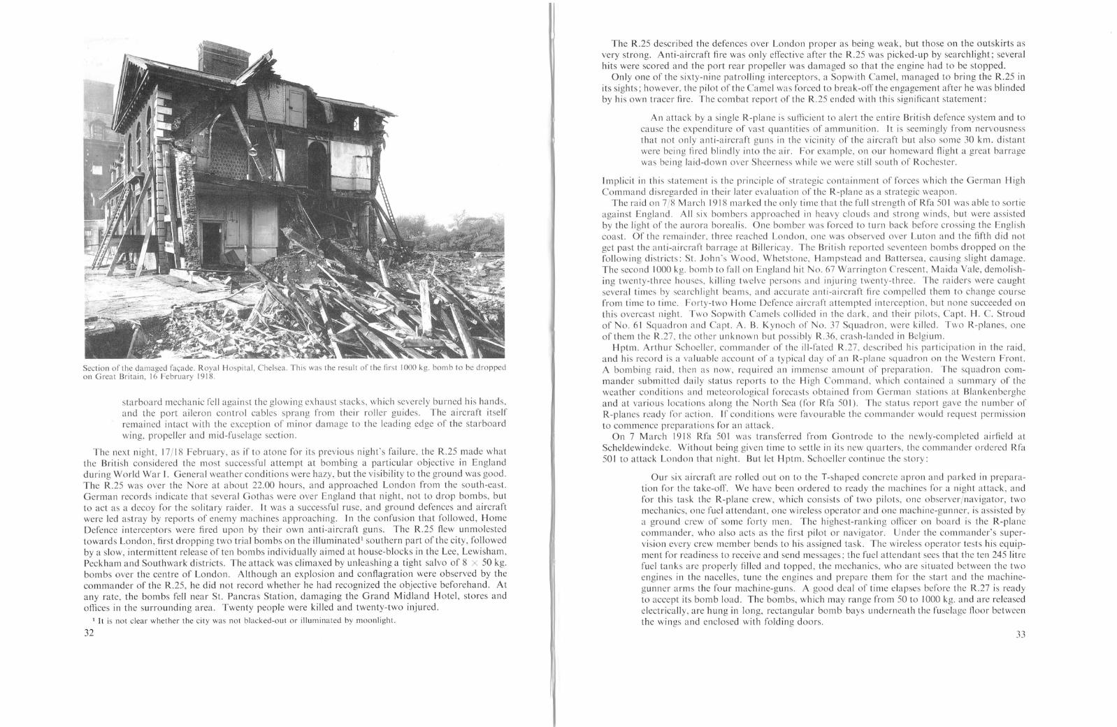
starboard mechanic fell against the glowing exhaust stacks, which severely burned his hands,and the port aileron control cables sprang from their roller guides. The aircraft itselfremained intact with the exception of minor damage to the leading edge of the starboardwing, propeller and mid-fuselage section.
The next night, 17/18 February, as if to atone for its previous night's failure, the R.25 made whatthe British considered the most successful attempt at bombing a particular objective in Englandduring World War 1. General weather conditions were hazy, but the visibility to the ground was good.The R.25 was over the Nore at about 22.00 hours, and approached London from the south-east.German records indicate that several Gothas were over England that night, not to drop bombs, butto act as a decoy for the solitary raider. It was a successful ruse, and ground defences and aircraftwere led astray by reports of enemy machines approaching. In the confusion that followed, HomeDefence interceptors were fired upon by their own anti-aircraft guns. The R.25 flew unmolestedtowards Londol~, first dropping two trial bombs on the illuminated l southern part of the city, followedby a slow, intermittent release of ten bombs individually aimed at house-blocks in the Lee, Lewisham,Peckham and Southwark districts. The attack was climaxed by unleashing a tight salvo of 8 x 50 kg.bombs over the centre of London. Although an explosion and conflagration were observed by thecommander of the R.25, he did not record whether he had recognized the objective beforehand. Atany rate, the bombs fell near St. Pancras Station, damaging the Grand Midland Hotel, stores andoffices in the surrounding area. Twenty people were killed and twenty-two injured.
1 It is not clear whether the city was not blacked-out or illuminated by moonlight.
32
The R.25 described the defences over London proper as being weak, but those on the outskirts asvery strong. Anti-aircraft fire was only effective after the R.25 was picked-up by searchlight; severalhits were scored and the port rear propeller was damaged so that the engine had to be stopped.
Only one of the sixty-nine patrolling interceptors, a Sopwith Camel, managed to bring the R.25 inits sights; however, the pilot of the Camel was forced to break-off the engagement after he was blindedby his own tracer fire. The combat report of the R.25 ended with this significant statement:
An attack by a single R-plane is sufficient to alert the entire British defence system and tocause the expenditure of vast quantities of ammunition. It is seemingly from nervousnessthat not only anti-aircraft guns in the vicinity of the aircraft but also some 30 km. distantwere being fired blindly into the air. For example, on our homeward flight a great barragewas being laid-down over Sheerness while we were still south of Rochester.
Implicit in this statement is the principle of strategic containment of forces which the German HighCommand disregarded in their later evaluation of the R-plane as a strategic weapon.
The raid on 7/8 March 1918 ma rked the on Iy ti me tha t the full strength of Rfa 50 I was able to sortieagainst England. All six bombers approached in heavy clouds and strong winds, but were assistedby the light of the aurora borealis. One bomber was forced to turn back before crossing the Englishcoast. Of the remainder, three reached London, one was observed over Luton and the fifth did notget past the anti-aircraft barrage at Billericay. The British reported seventeen bombs dropped on thefollowing districts: St. John's Wood, Whetstone, Hampstead and Battersea, causing slight damage.The second 1000 kg. bomb to fallon England hit No. 67 Warrington Crescent, Maida Vale, demolishing twenty-three houses, killing twelve persons and injuring twenty-three. The raiders were caughtseveral times by searchlight beams, and accurate anti-aircraft fire compelled them to change coursefrom time to time. Forty-two Home Defence aircraft attempted interception, but none succeeded onthis overcast night. Two Sopwith Camels collided in the dark, and their pilots, Capt. H. C. Stroudof No. 61 Squadron and Capt. A. B. Kynoch of No. 37 Squadron, were killed. Two R-planes, oneof them the R.27, the other unknown but possibly R.36, crash-landed in Belgium.
Hptm. Arthur Schoeller, commander of the ill-fated R.27, described his participation in the raid,and his record is a valuable account of a typical day of an R-plane squadron on the Western Front.A bombing raid, then as now, required an immense amount of preparation. The squadron commander su bmi tted daily status reports to the High Comma nd, wh ich conta ined a su mmary of theweather conditions and meteorological forecasts obtained from German stations at Blankenbergheand at va rious loca tions along the North Sea (for Rfa 501). The sta tus report gave the number ofR-planes ready for action. If conditions were favourable the commander would request permissionto commence preparations for an attack.
On 7 March 1918 Rfa 50 I was transferred from Gontrode to the newly-completed airfield atScheldewindeke. Without being given time to settle in its new quarters, the commander ordered Rfa50 I to attack London that night. But let Hptm. Schoeller con ti nue the story:
Our six aircraft are rolled out on to the T-shaped concrete apron and parked in preparation for the take-off. We have been ordered to ready the machines for a night attack, andfor this task the R-plane. crew, which consists of two pilots, one observer/navigator, twomechanics, one fuel attendant, one wireless operator and one machine-gunner, is assisted bya ground crew of some forty men. The highest-ranking officer on board is the R-planecommander, who also acts as the first pilot or navigator. Under the commander's supervision every crew member bends to his assigned task. The wireless operator tests his equipment for readiness to receive and send messages; the fuel attendant sees that the ten 245 litrefuel tanks are properly filled and topped, the mechanics, who are situated between the twoengines in the nacelles, tune the engines and prepare them for the start and the machinegunner arms the four machine-guns. A good deal of time elapses before the R.27 is readyto accept its bomb load. The bombs, which may range from 50 to 1000 kg. and are releasedelectrically, are hung in long, rectangular bomb bays underneath the fuselage floor betweenthe wings and enclosed with folding doors.
33

34
On top of these preparations there is just enough time for a frugal supper and dissemination of orders. A last comprehensive study of charts and orientation material with myobserver, Oberleutnant Gunther Kamps and the second pilot U nteroffizier Buhler, then outto the armed R.n, whose idling engines sing a song of subdued power. At exactly 20.00hours Hptm. von Bentivegni fires the starting flare and the first of the R-planes strainsforward with an ear-deafening roar. We are next to taxi to the take-off strip and ten minutesafter the first aircraft, with full throttle R.27 heads into the clear dark night.
Slowly the heavily-loaded machine rolls over the ground; finally it is airborne, and aftera wide curve around the aerodrome we head in a direction along the pin-marked course onour maps. Inside the fuselage the pale glow of dimmed lights outlines the chart-table, thewireless equipment and the instrument panel, on which the compass and other navigationinstruments are mounted to help guide us through the darkness. Before long, we spot thesignal cannon at Ostend, which fires star shells into the night to assist us on our way.
We approach the coast; the night is so dark that the coastline below is but a mere suggestion. Under us is a black abyss, no waves are seen, no lights of surface vessels flicker as wehead for the Thames estuary at Margate. On our right, in the distant north, is our onlylight, the weak pulsating glow of the aurora borealis. Ahead of us a black nothingnessare we on the correct course? We have neither a weather report from the high seas [note:presumably from German submarines] nor wind measurements to go by.
The R.27 started in clear sky. Now thin but continually thickening cloud shreds streakpast. We climb over the cloud cover, through which holes now and then appear, but beneathnothing is sighted, although from our elapsed time we must now be over England. Theflight continues without a sighting; did we possibly miss the English coast? Suddenly, abreath of relief. Directly ahead the searchlights illuminate the sky in their hunt for us, theirbright beams making glowing circles in the thin overcast, but do not spot us. Now we arecertainly over England, but where? Because all surface lights are blacked out, it appears asif we are soaring over a dead land. But the enemy has heard us, therefore we are free torequest wireless bearings. The operator sends a pre-arranged signal which is received by twospecially-alerted stations in Belgium. ]n a few minutes we receive a message giving ourlocation at the time we flashed our signal. We are south-east of London.
Accompanied by searchlights which seem to guide our way, we fly towards the Thames,whose dock installations are our target. Can we recognize the docks through the lowovercast, against the darkened countryside which lies beneath? Directly ahead, the landinglights of an English airfield flare up as the enemy prepares to intercept us. The machinegunners arm their guns and fire at the searchlights below. On this particularly bright-litaerodrome Obit. Kamps releases four bombs, and the detonations are clearly seen. This isin return for attacks on our aerodromes. All at once, through a hole in the cloud cover thegrey band of the Thames momentarily appears. We continue on course, and during the nextsighting Obit. Kamps, who is standing next to the bomb-release mechanism in the open bowof the machine, presses the bomb-release keys. Not far ahead we can see a portion of theballoon barrage which surrounds London's eastern and southern periphery.
We turn for home along the Thames, whose banks are dotted with anti-aircraft batteriesthat soon have us under fire. As we approach the coast the overcast becomes thinner andthinner; before long the searchlights catch us and the bursts of the anti-aircraft movedangerously closer. A shell splinter tears through our upper wing without causing anydamage. The flaming shells come so close we can almost touch them. Beneath us, we spotthe exhaust flames of a pursuing night fighter, but it does not threaten us. In this manner,we reach the open sea at Margate and steer for Ostend, where well-known signals will guideus home. After a seemingly endless flight, they come into view and we feel secure again.
But fate wills differently. As we come into sight of the coast, the steady rhythm of ourengines begins to falter, until suddenly all four propellers stop. Some split- econd thinking:the fault can only be in the fuel system. The last two fuel tanks had just been connected.What had happened? The fuel lines had frozen due to water-contaminated gasoline. To
thaw them out is impossible, and so a forced landing becomes a certainty. The question is,will we reach the coast, or are we to sink in the sea? ]n any case, life-jackets are strappedon. Fortunately the great gliding qualities of our R-plane enable us, in spite of stoppedengines, to reach the coast behind our own front which we recognize from the firing ofarti lIery.
By means of flares we search the darkened landscape on which we must land, but onlytrenches and hollows are discernible. At best, the landing will end in a crash, but it meansannihilation if the heavy, ponderous machine should collide with an obstacle on the ground.Therefore, by pulling sharply on the controls I stall the aircraft letting it fall almost vertically against the ground. With a mighty impact it hits in front of a wide ditch. The rightlanding gear collapses and the right lower wing shatters, but no crew member is injured.
At 04.30 hours we find ourselves close to a command bunker of an infantry brigade, andlike shipwrecked sailors we are hospitably received. We notify our squadron, which makesarrangements to save valuable instruments and the engines from the wrecked R.27, whichlater was destroyed by enemy shell-fire. A few days later, the whole crew is on the way tothe Schutte-Lanz Works at Zeesen to pick up a replacement for the R.27 in the form of theR.28 and deliver it to the front.
The full strength of the London squadrons was mustered for a final all-out attack on London duringthe night of 19/20 May 1918. The German force was composed of thirty-eight Gothas, three R-planes,and two C-types armed with a total of 14,550 kg. high explosives, including one 1000 kg. bomb.
Part of the damage in Warrington Crescent caused by the 1000 kg. bomb dropped by the R.39 during the raid of7/8 March 1918.
35

Thirty-four aircraft reached the English coa t, and of these eighteen Gothas and one R-planesucceeded in piercing the London defence system. Criss-crossing London from ~II directions, the raidersstrewed seventy-two bombs on the city, while other aircraft dropped thlrty- IX and forty-nine bO~lbs
on Essex and Kent respectively. The total casualty list as reported by the Bntlsh was qUltc high:forty-nine persons killed and 177 injured, but the British authorities considered the effect of the raidlight in relation to the ize of the attacking force. Two R-planes discharged their bombs, Including
Staaken R.YI 30'16 prepared for flight. Before installation of supercharger. OberleCltnant Meyer is the pilot.
the third and la t 1000 kg. bomb to fall on ngland during the war, but the damage reported wasslight. 1 Six Gothas were lost in this last great raid; however, the three R-planes returned safely totheir base.
This marked the last of the raids on Great Britain, for the aircraft were urgently required elsewhere.Germany had begun the final and most desperate offensive campaign of the war, and every availableweapon in her ar enal was placed in support of her ground forces in France. The pos ibility ofbombing England again at some later date still existed, and indeed, in early August 1918, fourBombengeschwader (including Bombengeschwader 3) were poised to attack London and Pari withthe newly-perfected "Elektron" incendiary bomb weighing but I kg. The High Command, however,cancelled the raidsju t one half-hour prior to take-off time. Later in August the question of bombingLondon and Paris was definitely settled. The war had irretrievably turned in favour of the Allies, andthe so-called "propaganda" raids on England and France would no longer have served their purpo e.In the face of imminent defeat, the German High Command forbade bombing attacks on London andParis for military-political reasons.
So ended the R-plane attacks on England. Itogether eleven raid by a total of twenty-eightR-planes were flown against England by the crews of Rfa 501 in a period of about eight month.Rfa 501 dropped 25,970 kg. of high explosive bomb (including three 1000 kg. bombs) and 1220 kg.of incendiary bombs on England, for a total of 27,190 kg. all told.
1 Actually R-plane crews preferred to carry Ihree 300 kg. bombs which were known to be far more effective Ihan asingle 1000 kg. bomb.
36
It is a remarkable fact that Rfa SOL suffered no personnel or aircraft losses by encmy action duringits raids on England. Two R-planes crash-landed in Belgium for other reason. In harp contrasttand the los es of Bombengeschwader 3, which totalled sixty-one aircraft; twenty-four were lost as
a re ult of enemy action and thirty-seven were lost due to landing mishaps, fire and crashe. Thenumber of men lost by Bombenge chwader 3 has not been determined, although a reasonably closeestimate based on the total lost during the war (137 men) would be between 80 and 100 men. l
Staaken R.YI(Av) of Rfa 500.
What conclusions did the Germans reach regarding the R-plane's accomplishments in the light ofthe England raids? According to the German historian von Bulow, the reinforcement of Bombengeschwader 3 by the giants of Rfa 501 did not come up to German expectations. Von Bulow's firstcriticism was that the bomb load carried by an R-plane was small compared to the aircraft's totalweight. But this criticism could just as well have been levelled against the Gotha as a bomb-carrier,for analysis shows that both aircraft carried about 8 per cent of their total weight in bombs. Forshort-range attacks the Gotha was more efficient in terms of bomb load carried, but for the Englandraids the bomb load was reduced to carry extra fuel. And it should be remembered that the R-plane'stotal weight included additional engines, which made the R-plane much safer, more difficult to shootdown and more reliable than the twin-engined Gotha.
Although R-planes dropped 27,190 kg. of bombs on England, von Bulow continued, this total mustbe equated against the cost, time and effort required to con truct and equip an R-plane, not tomention the vast number of rear echelon personnel and supplies necessary to keep an R-plane in theair. 2 Even then, the R-plane was seldom ready for deployment. Of the six R-plane available toRfa 501, only in one instance did all six machines take part in a raid. Had it been pos ible for all sixR-planes, each carrying a 600-1000 kg. bomb load. to start on every mission and have at least fourR-planes hit the target, then, von Bulow felt, the R-plane could have achieved great success. Throughout the war, the R-plane was never quite ready for continued front-line service; it was simply toocomplex, too cumbersome and too dependent on specially-constructed airfields and service facilities.
I For a statistical comparison of both squadrons see Appendix 5.2 The strength of Rfa 501 was about 750 men and six aircraft, which meant that 125 men were required to keep
one R-plane in operational service.
37

WESTERN FRONT OPERATIONS
, Very little has been written about the service record of R-plane squadrons operating against targets111 .Fra~ce. This lac~ of documentation may well be attributed to the fact that the R-plane was usedpr.lm.anly as a tactical rather than as a strategical weapon on the Western Front. Although itsmiSSions here. were even more ~azardous, the tactical employment of the R-plane was less glamorousand had less I~pact on t~e Alited war effort. The G-type bombers, being more effective for tacticalpurposes,. rece.lved the biggest share of the glory. It was a time when the urgency of the GermanmIlItary situatIOn f~rced t~e ~-plane into a role for which it was ill-suited. R-plane targets in France:vere ge~erally tactIcal obJectIves, such as rail junctions, supply dumps, assembly areas and otherJIlstall~tlons close to the front-lines. In isolated cases long-range attacks against Paris, Ie Havre.Deauvtlle, Rouen .and several other cities were performed, but these raids were the exception ratherthan the rule. So 111 the ~ummer of 1918 German military planners chose to disregard the differencesbetween short-range tactl~al and I.ong-range strategic bombers, and gambled everything in support oftheIr last ~esperate offensive. It IS felt that the original objectives of the R-plane squadrons shouldhave remall1ed targets deep within ~nemy territory, beyond the range of any other aircraft. Againsttargets such as London and Pans, Just a few R-planes would have successfully continued to divertbadly-need~d Inter~eptor squadrons, anti-aircraft batteries and troops from the front.
In attacking tactIcal targets the advantage of surprise was 10 t, and in addition the R-plane wasexposed ~o esta.bllshed defences of rear sectors. Furthermore, the R-plane was not nearly as flexibleas t~e tWln-~ngll1~d ~-types. On the night of 21/22 July 1918 everal crews of Bombengeschwader 4.equIpped WIth Fnednchs~a~en bomb~rs, managed to complete six missions. An R-plane could onlyhope, to complete one mIssIon per nIght, regardless of the distance involved, because of the timerequIred to prepare the machine for flight. Consequently, it would have made sense to exploit the
In this critici m von Bulow was essentially correct. The fact was that there simply were not enoughR-planes constructed to perform a greater number of missions. On the other hand, von Bulow, incriticizing the R-plane's poor ervice availability, did not, it seems, take into account the raids flownby Rfa SOL against France during periods when it was not bombing England, nor instances whenR-planes had taken-off but were forced back by weather. The list below, though incomplete, doesshow that Rfa SOL was active against continental targets on off-days during the England campaign. l
Although the full number of these "secondary" missions is not known, there can be no question thatthe R-plane possessed better service availability than von Bulow thought.
One factor not considered by von Bulow was the R-plane's ability to complete a mission oncehaving started. According to available records, twenty-eight out of a total thirty R-planes that tookoff for England managed to drop their bombs on ngland, or in other words 93-4 per cent of themachine completed their mis ion as compared to the Gotha bomber's 76-4 per cent. Obviou Iy thegreater reliability provided by four or more engines gave the Staaken R-planes a distinct advantageover the G-type bombers not only in their ability to complete an attack but also to return home safely.
Finally, the R-plane was a strong opponent and difficult to shoot down, as demon trated by thefact that none were lost to enemy action during the England raids. The R-plane was provided withfour to seven machine-gun with overlapping fields of fire, so that several guns could be trained onone attacker. The Briti h pilots were fooled by the R-plane's size, and consequently opened fire beforecoming within range. In addition, the ·303 calibre machine-gun bullet was too small to deal effectivelywith the giants unless the range was very close. 2 Perhap this was the reason why the Germans wereplanning to install one or more 2 cm. Becker cannon on late model aircraft. Thi would have madethe R-plane an even tougher nut to crack.
One get the impre sion from reading von Bulow's account of the England raid that the Germansplaced the greater empha is on the tactical succe s of the bombers (i.e. the destruction of targets)rather than giving first consideration to what was suppo ed to be the primary objective of the Englandraids: trategic propaganda to destroy the morale of the English people and their will to fight. Theextensive countermeasures taken by the British Government showed that it wa exceedingly concerned over the effect the bombing raids might have on the British people; and indeed the situation onthe Home Front almost reached crisis proportions, although the British people did not crack. In thispropaganda objective, then, the bombing raids failed, but the Germans seem to have almost completely neglected to take into account the large amount of troops and quantity of material drained-offfrom the We tern Front by the British to combat the bomber menace. It is interesting to note thatout of the last nine raids on England, five were flown exclusively by Rfa 501. While Bombengeschwader 3 wa either grounded or attacking targets in France, the R-plane was able to maintain pre ureon England and tie down a vast defen ive system out of all proportion to the relatively small effortexpended by the Germans. The raid of the R.25 on 17jl8 February 1918 was graphic evidence of howa single R-plane could evoke a massive response by the British.
It was a strategic mistake by the Germans not to continue their night attacks by R-planes on England and other large cities. This would have been far more profitable for the German than squandering the long-range capability of the R-plane on short-range tactical targets, as was later the case onthe We tern Front.
1 Known sortie by Rfa 501 during time of the England raids: R.39 was in the air on 1 October 1917, one R-planeattacked Dunkirk in the first week of November 1917, three R-planes were forced back by fog from a raid on Englandon 25 December 1917 and bombed Boulogne instead; Rfa 501 was slated to bomb Paris 011 11/12 March 1918 withBombengeschwader I, 2, 5 and 7, but could not participate due to ground fog covering the airfield; R.39 bombedBoulogne and St. Omer on I April and 21 April 1918 respectively, possibly accompanied by other R-planes, and on9/10 May 1918 four R-plane from Rfa 50 I bombed Calais-Dunkirk. For additional raids ee Appendix 7.
2 To shoot down the RA3, Capt. Yuille closed to within 25 yards before opening fire (see Staaken R.XI V chapter).
38Hptm. Schilling with officers of Rfa 500 in front of Staaken R.VI(Av) 33/16.
D 39

Staaken R. VI(Albs) 36/16, and R. VI(Av) 33/16 of Rfa 500 being prepared for flight.
lost as a result of enemy action since the operational debut of the giants in 1915. The R.37 was notdestroyed as completely as its crew might have desired, and parts of the aircraft were scrutinized byAllied experts. Because it was the first machine of its kind to be examined close-up, it became thesubject of much attention by the British and French Press.
A classic example of the tactical misuse of the R-plane took place on 10/11 August 19 18, when theRA3 of Rfa 501 was shot down while attacking Doullens. (For details see Staaken R.XIV chapter.)The target was located only 25 km. behind the front lines, yet on the same night G-type bombersattacked Etaples, a city situated deeper in enemy territory than Doullens. This was the first of twovictories that Allied aircraft had in dealing with the giant bomber. Two factors contributed to theloss of the RA3. One, it was attacked by specially-trained pilots of a British night fighter squadronand, two, the RA3, by attacking an objective close to the front lines, had exposed itself to the concentrated defences of the rear sectors.
Staaken R.XIV43'17 in flight.
Similarly, on the next night (11/12 August) the R.52 was ordered to bomb the small, blacked-outtown of Beauvais, only some 50 km. from the front lines. It was on this raid that Hptm. ErichSchilling, commanding officer of Rfa 500, and four other members of the crew were killed. The R.52was a new machine, heavier than previous types, and the pilots were unaccustomed to the changedposition of the cockpit. (See Staaken R.VI chapter.) It was a pitch-black night over Villers la Tourwhen the R.52 side-slipped, caught itself and side-slipped again. The right wing hit the ground, andfuel from burst tanks spilled over the hot engines and ignited. This was the only instance when anoperational R-plane crashed as a result of uncontrollable flight manoeuvres.
An analysis of the distance between the targets (see Appendix 7) and existing front-lines shows that.with the exception of Rouen, Ie Havre and Deauville, all targets were located within 100 km. of thefront lines, and in most cases even less.
Although these bombing raids were generally short-range missions during which the navigatorcould rely greatly on visual navigational fixes such as landmarks, starshells, searchlights, etc.. theR-plane wireless communication techniques had not been neglected. The Rfa 501 combat report for
41
.~~':........ - - ...... :
great range of the R-plane and leave short, repetitive raids to aircraft designed for this purpose. Inthe final offensive gamble the R-plane became a victim of expediency.
After its last London raid Rfa 501 continued to operate from Scheldewindeke against Frenchtargets until the end of the war. Rfa 500 was transferred from Dbberitz to Custinne (in France)during February 1918, specifically (according to British intelligence reports) to bomb Paris.1 Frenchsources list a total of twenty-eight raids against Paris and its outskirts by German bombers in 1918,but R-planes are mentioned as participating in only one raid. On the night of 1/2 June 1918 elevenbombers, including two R-planes from Rfa 500, attacked Pari. One machine, the R.37, was firedat by four French anti-aircraft batteries, forcing it to crash-land near Betz. The R.37 was set afire byits crew of three officers and seven men before being captured. 2 This was the first R-plane confirmed
1 Rfa 500 was reported by British intelligence as being stationed at Custinne (February-May 1918), Morville inBelgium (May 1918), Dinant area, probably Morville (June-August 1918) and Morville (August-Septem bel' 1918).
2 A British report stated the crew of the R.37 escapee!.
40
The same two aircraft lined up. The balanced ailerons and central fin of R.36, the nearest machine shows this tobe a later model than its companion.

24/25 August 1918 not only demonstrates the degree of sophistication achieved in the realm of airborne wireless communications but also indicates by its matter-of-fact attitude the amount of progresswhich had been made, both operationally and technically, within a time span of two years.
As a word of explanation it should be noted that the command of the aircraft rested not with thefirst pilot but with an officer who, in addition to his all-important navigation duties, kept abreast ofthe weather situation by wireless and chose new targets or landing fields as dictated by weatherchanges. There can be no question that a high degree of skill and alertness was required for theformidable task of finding the target and bringing the aircraft safely home at night. All R-planeswere equipped with a small, two-cylinder petrol-driven engine which drove a 1000-watt generator.
Remains of the Staaken R.XlV 43/17, shot down by Capt. Yuille R.F.C.
This in turn supplied power to a receiver/transmitter which operated on a wavelength of 300-1000metres and had a nominal range of 600 km. The equipment, built either by Telefunken Gesellschaftor Dr. Erich F. Huth, G.m.b.H., was used to establish the position of the aircraft by a triangulationmethod,! to keep abreast of sudden changes in the weather and to pass on commands to other R-planesen route to the target.
As an example ofa typical mission using wireless command procedures, Hptm. von Bentivegni hadthis to say in an official combat report:
Report of attack on targets Band C on night of 24/25 August 1918: During a spell offavourable weather, an attack on targets chosen by the Armee Oberkommando 4 (Army
1 When the navigator wanted a position Ax he would transmit a signal which would be picked up by two speciallyalerted ground stations. Both stations would take a bearing on the R-plane·s signals, determine its position andtransmit this information back to the R-plane, providing the navigator with a reasonably accurate Ax. Not all navigation was done by wireless; the Germans had also established an extensive network of pre-arranged coloured searchlights, periodic star shells and other light signals for all their night-flying aircraft, from single-seaters to R-planes.
42
Command 4) was ordered by me as follows: Target: A; Alternative targets: B (Gravelines)and C; Fuel for 61- hours; Bomb load; 1200 kg. each; Aircraft: R.12, R.13, R.25, R.39.
I am aboard R.39. Permission was given to take-off any time after 17.30 hours. Approachto target A (a French coastal city) over the sea. This approach was mandatory to avoidunnecessary exposure from anti-aircraft fire on the moonlit night. It was especially distut"bing that we were not allowed to fly directly across the German night pursuit sector,because the route along the Dutch frontier required longer flying time and there was adanger of crossing the Dutch border. During the approach flight a weather report warnedthat fog would have to be reckoned with after 03.00 hours. After receiving this wirelessmessage, I calculated that it was impossible for all aircraft to land before 03.00 hours.Consequently, I directed a wireless order to the squadron to attack auxiliary target B(Gravelines). This order was received by all aircraft. Target B was attacked by threeaircraft, which dropped 3600 kg. of explosive bombs with unquestionably good results. Thefourth aircraft attacked target C due to engine trouble. All aircraft returned safely.
Staaken R.xlV 45/17. Photograph shows the condition of the machine after a night landing at Morville, Belgium.Notice the position of the cockpit behind the wings, unique to the R.45 among Staaken R-planes.
From the standpoint of the crew, an R-plane raid was an exciting adventure as indicated byWilhelm Pfaff's recollections of a raid on Ie Havre by Rfa 500:
Prior to take-off, as was customary, only the commander and the two pilots were giventhe name of the target. The rest of the crew did not find out until the aircraft had returned.At dusk the R.45 took-off from Morville. It became dark and soon we were over the front,which was illuminated by a fierce gun battle raging below on both sides. Over the front wewere not fired at by anti-aircraft guns; this aroused our suspicions and we kept a sharplook-out for enemy night fighters. But nothing happened. As we penetrated deep intoenemy territory, we could still see behind us the shell bur ts and fires around St. Quentin.Suddenly in the vicinity of Amiens searchlights and brisk anti-aircraft fire appeared; thenit was again quiet for a long time. The commander opened the door to my engine-room inthe nose of the aircraft and gave the sign to fuse the bombs. I laid myself on my stomach,opened a bomb-bay hatch and fused one bomb after the other. While 1 was working on thelast bombs, I noticed that several had been released. 1 remained lying in the inner fuselageto observe if all bombs had been dropped. In the meantime, the first bombs must have hitthe ground, for in an instant, as though someone had pressed a button, we were flooded bythe glare of searchlights. It seemed to me as if we were bathed in flames. Noticing that thebombs were all gone, I closed the bomb-bay door, and as 1 got up the first pilot made a signfor me to hold on. At this moment, when our lives depended on split-second timing, theactions of the two pilots were not co-ordinated. The first pilot wanted to put the aircraftinto a dive, and the other pilot wanted to climb. At his signal I gave the first pilot a handand the R.45 went into a dive. While this was happening the searchlights lost us and theanti-aircraft batteries had to cease fire. All this lasted only a few seconds, but it cannot be
43

described by words or in writing. It must be experienced. It was estimated that forty tosixty searchlights had captured us in their beams, in addition to anti-aircraft shells explodingon all sides of us. But the daring dive gave us greater speed, which enabled us to escape thishell. From my long experience I could see that all my comrades had remained calm andcollected throughout the action. I went forward to my post in the nose engine-room. Withmy ear against the wooden handle of a screwdriver I listened to one cylinder after the other,and gave the valves a squirt with the oil-can. The engine sounded fine. From my windowI could see that we were over the sea and guessed that the commander had chosen theshortest route back to Morville. Over the front we again came into contact with searchlights and anti-aircraft fire, but after having dropped our bombs we were able to fly at a higheraltitude, where the French defences could do us no harm. Furthermore, at this altitude wedid not fear interception by enemy night fighters. As I was checking my fuel consumption,the wireless operator nervously squeezed past in his haste to reach the commander with anurgent wireless message which said, "Do not land at Morville, enemy pilots overhead,airfield not illuminated." The commander went to his chart table and calculated the fuelrequirements to reach an alternate airfield. Then he gave the wireless operator the message:"Must land, no fuel, on landing approach make signals with flashlights." We cruisedseveral times around the airfield and the nose engine was stopped. The flashlights were easyto spot, but because men were running around with flashlights we had no indication of whatwas going on down below. The first and second landing attempts failed. For the thirdlanding attempt the commander gave me a flare pistol with ammunition. Quickly I went tothe window, opened it and shot one flare after the other in front of the aircraft to illuminatethe terrain ahead for the pilots. As the pilots saw the edge of the forest, they brought theR.45 down for a landing.
It was during this landing run that the R.45 was damaged. (See Staaken R.xIY chapter for details.)After Hptm. Schilling's death in August 1918 ObIt. Max Borchers, formerly with Rfa 501, was
named to command Rfa 500. Towards the end of the war the number of available R-planes dwindledand the service strength of Rfa 500 was reduced from six to finally one R-plane. Consequently,on 23 October 1918 Rfa 500 was merged into Rfa 50 I, and von Bentivegni came to Morville tolead the combined squadrons. Several unserviceable R-planes were left behind in the Ghent area.
OPERATIONAL LOSSES
The R-plane squadrons suffered the greatest proportion of their losses on the Western Front,where they were flown under conditions quite different from those on the Eastern Front. Allieddefences were strong, and every effort was being made to combat bombing attacks. Heavy antiaircraft batteries had been established in specific defence zones, night interceptor squadrons wereoperational, and night-bombing of German bomber airfields was an accepted routine. In spite ofenergetic Allied counter-measures, it is surprising that only three R-planes have been definitely confirmed as victims of enemy action. French anti-aircraft fire forced the R.37 to crash-land; the R.3land R.43 both fell to night-flying Sopwith Camels of lSI Squadron R.A.F. This total of threeR-planes tallies with von Biilow's count, although he does not cite particulars. One other giant, theR.34, crashed after combat, but it is not clear whether the cause was enemy action or some internalfailure.
In a sense, the R-plane was its own worst enemy if one considers that the majority of the operationallosses occurred while landing. The landing losses fall into two categories; those resulting from someemergency ituation and those during which an attempt was made to land under marginal weatherconditions. Most of these accidents happened in times of reduced visibility, at night or in foggyweather, which, of course, severely restricted the pilot's range of action. Another handicap was thatnight flying, a relatively new skill, required techniques that were not fully developed until many yearsafter the war. The R-plane's low landing speed was a saving grace which lessened impact forces and44
usually enabled aircrews to escape the fire which generally followed a crash. Casualty lists for theR-plane squadrons have not been published, but the officer casualties for operational R-planes seemreasonably low.
Allied intelligence bulletins contain a scattering of prisoners' (never identified but not necessarilyR-plane crews) and Belgian civilians' statements that the R-plane was too accident-prone. Thesestatements were probably true, for there were many minor landing mishaps (for instance, landing-gearcollapse) that were not serious but which kept the machine out of action until repairs could be made.
In Belgium the R-plane squadrons operated at a disadvantage with respect to the weather. TheWest European weather front generally moves in from the north-west, travelling across Great Britainbefore reaching the Continent. The German meteorology service possessed no sure means by whichto make long-range weather predictions. In some cases submarines would transmit weather reportsfrom the high seas, but this source of information could not be depended on. During the Englandphase of operations the bombers generally flew into an advancing weather front, which gave themample time to turn back and land safely or attack an alternative objective if the weather lookedominous. In France the situation, with exception of targets on the Channel coast, was reversed.After taking-off from Belgium the R-planes for the most part flew in the opposite direction from theoncoming weather front, and unless a timely wireless warning was received, the R-planes were liableto return and find their airfield closed-in by fog. This was exactly what happened on 9/10 May 1918,when four R-planes, although warned, found themselves separated from their airfield by a thick fogblanket after returning from a mission. The combat report prepared by surviving officers of Rfa SOltold in detail what had occurred:
Dornier Rs.IlI at Norderney. The only seagoing R-plane to be flown operationally during the war.
On 9 May 1918 four Staaken R.YI machines (R.26, R.29, R.32 and R.39) took-off at 22.05 hoursfrom Scheldewindeke to bomb Dover, but were ordered to attack the alternative targets CalaisDunkirk instead. The prevailing north-west wind was considered favourable because the aircraft,flying into the wind, would be able to anticipate oncoming bad weather. Orders had been given toreturn to the airfield immediately if a fog warning was received by wireless. R.32 and R.39 hadsuccessfully dropped their bombs on Dunkirk when a wireless message was received warning theaircraft that the amount of ground and low-altitude fog over the airfield was increasing. R.32 andR.39 headed back at once, but the two other aircraft flew on for they were just a short distance fromtheir target, Calais.
R.32 and R.39 arrived over their airfield shortly before a1.00 hours, when the airfield signalled bywireless: "Cloud height 100 metres, Brussels clear visibility." For reasons not documented, bothaircraft decided to risk the landing at Scheldewindeke in spite of the wireless warning. The elapsedtime between the wireless message and landing attempt was about 25 minutes, during which time a fogbank had descended on the airfield. The R.32 made several landing approaches, but each time it lostits direction in the fog. The searchlight beacons could be seen from the top of the fog layer as washedout circles of light. Tt was these beacons that established the position of the airfield. However, as it
45
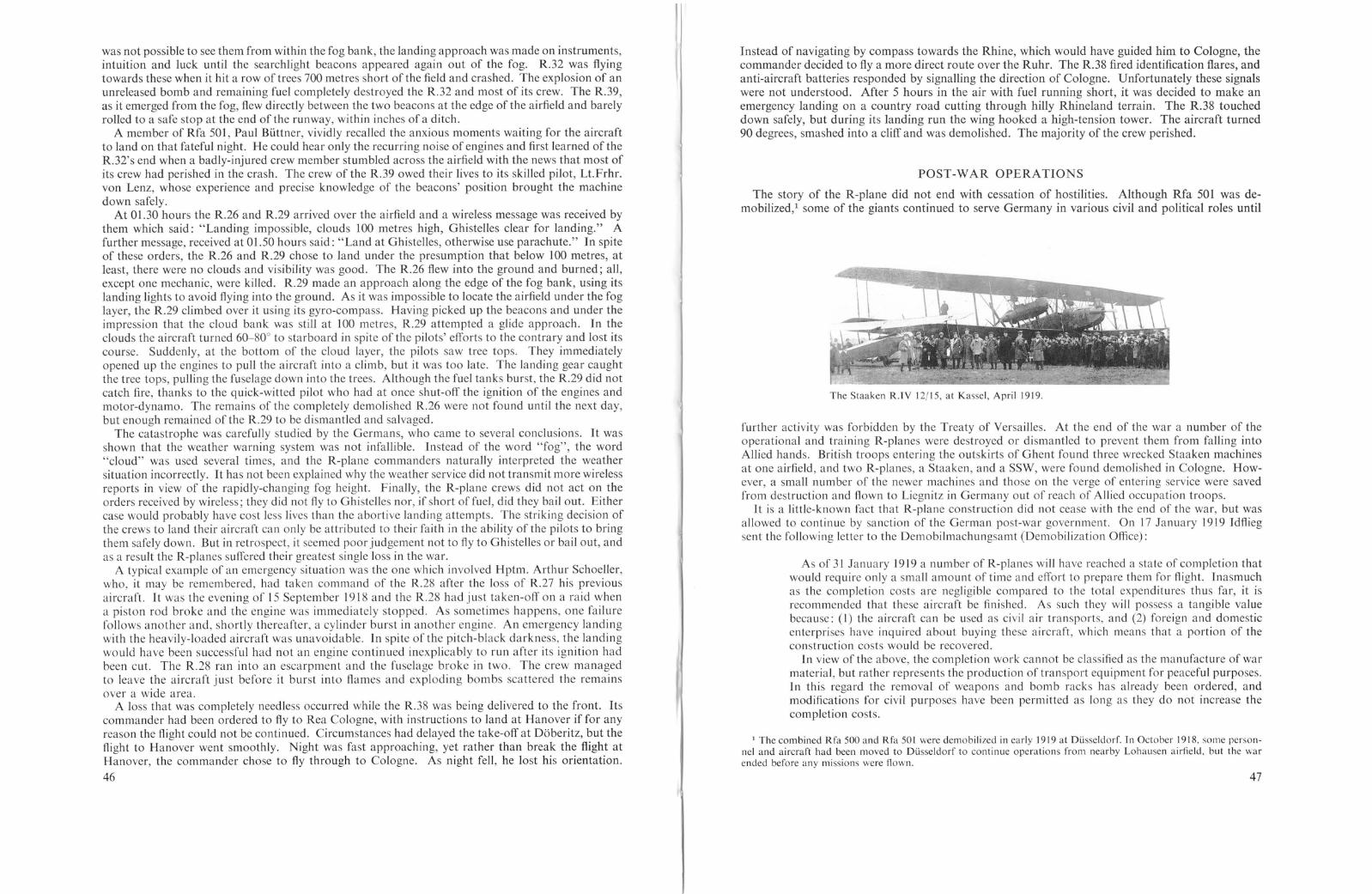
was not possible to see them from within the fog bank, the landing approach was made on instruments,intuition and luck until the searchlight beacons appeared again out of the fog. R.32 was flyingtowards these when it hit a row of trees 700 metres short of the field and crashed. The explosion of anunreleased bomb and remaining fuel completely destroyed the R.32 and most of its crew. The R.39,as it emerged from the fog, flew directly between the two beacons at the edge of the airfield and barelyrolled to a safe stop at the end of the runway, within inches ofa ditch.
A member of Rfa 501, Paul Biittner, vividly recalled the anxious moments waiting for the aircraftto land on that fateful night. He could hear only the recurring noise of engines and first learned of theR.32's end when a badly-injured crew member stumbled across the airfield with the news that most ofits crew had perished in the crash. The crew of the R.39 owed their lives to its skilled pilot, Lt.Frhr.von Lenz, whose experience and precise knowledge of the beacons' position brought the machinedown safely.
At 01.30 hours the R.26 and R.29 arrived over the airfield and a wireless message was received bythem which said: "Landing impossible, clouds 100 metres high, Ghistelles clear for landing." Afurther message, received at 01.50 hours said: "Land at Ghistelles, otherwise use parachute." In spiteof these orders, the R.26 and R.29 chose to land under the presumption that below 100 metres, atleast, there were no clouds and visibility was good. The R.26 flew into the ground and burned; all,except one mechanic, were killed. R.29 made an approach along the edge of the fog bank, using itslanding lights to avoid flying into the ground. As it was impossible to locate the airfield under the foglayer, the R.29 climbed over it using its gyro-compass. Having picked up the beacons and under theimpression that the cloud bank was still at 100 metres, R.29 attempted a glide approach. In theclouds the aircraft turned 60-80° to starboard in spite of the pilots' efforts to the contrary and lost itscourse. Suddenly, at the bottom of the cloud layer, the pilots saw tree tops. They immediatelyopened up the engines to pull the aircraft into a climb, but it was too late. The landing gear caughtthe tree tops, pulling the fuselage down into the trees. Although the fuel tanks burst, the R.29 did notcatch fire, thanks to the quick-witted pilot who had at once shut-off the ignition of the engines andmotor-dynamo. The remains of the completely demolished R.26 were not found until the next day,but enough remained of the R.29 to be dismantled and salvaged.
The catastrophe was carefully studied by the Germans, who came to several conclusions. It wasshown that the weather warning system was not infallible. Instead of the word "fog", the word"cloud" was used several times, and the R-plane commanders naturally interpreted the weathersituation incorrectly. It has not been explained why the weather service did not transmit more wirelessreports in view of the rapidly-changing fog height. Finally, the R-plane crews did not act on theorders received by wireless; they did not fly to Ghistelles nor, if short of fuel, did they bailout. Eithercase would probably have cost less lives than the abortive landing attempts. The striking decision ofthe crews to land their aircraft can only be attributed to their faith in the ability of the pilots to bringthem safely down. But in retrospect, it seemed poor judgement not to fly to Ghistelles or bailout, andas a result the R-planes suffered their greatest single loss in the war.
A typical example of an emergency situation was the one which involved Hptm. Arthur Schoeller,who, it may be remembered, had taken command of the R.28 after the loss of R.27 his previousaircraft. [t was the evening of 15 September 1918 and the R.28 had just taken-off on a raid whena piston rod broke and the engine was immediately stopped. As sometimes happens, one failurefollows another and, shortly thereafter, a cylinder burst in another engine. An emergency landingwith the heavily-loaded aircraft was unavoidable. [n spite of the pitch-black darkness, the landingwould have been successful had not an engine continued inexplicably to run after its ignition hadbeen cut. The R.28 ran into an escarpment and the fuselage broke in two. The crew managedto leave the aircraft just before it burst into flames and exploding bombs scattered the remainsover a wide area.
A loss that was completely needless occurred while the R.38 was being delivered to the front. Itscommander had been ordered to fly to Rea Cologne, with instructions to land at Hanover if for anyreason the Right could not be continued. Circumstances had delayed the take-off at Dbberitz, but theRight to Hanover went smoothly. Night was fast approaching, yet rather than break the flight atHanover, the commander chose to fly through to Cologne. As night fell, he lost his orientation.
46
Instead of navigating by compass towards the Rhine, which would have guided him to Cologne, thecommander decided to fly a more direct route over the Ruhr. The R.38 fired identification flares andanti-aircraft batteries responded by signalling the direction of Cologne. Unfortunately these si~nalswere not understood. After 5 hours in the air with fuel running short, it was decided to make anemergency landing on a country road cutting through hilly Rhineland terrain. The R.38 toucheddown safely, but during its landing run the wing hooked a high-tension tower. The aircraft turned90 degrees, smashed into a cliff and was demolished. The majority of the crew perished.
POST-WAR OPERATIONS
The story of the R-plane did not end with cessation of hostilities. Although Rfa 501 was demobilized,l some of the giants continued to serve Germany in various civil and political roles until
The Staaken R.TY 12/15, at Kassel, April 1919.
further activity was forbidden by the Treaty of Versailles. At the end of the war a number of theoperational and training R-planes were destroyed or dismantled to prevent them from falling intoAllied hands. British troops entering the outskirts of Ghent found three wrecked Staaken machinesat one airfield, and two R-planes, a Staaken, and a SSW, were found demolished in Cologne. However, a small number of the newer machines and those on the verge of entering service were savedfrom. destruction and Rown to Liegnitz in Germany out of reach of Allied occupation troops.
It IS a lIttle-known fact that R-plane construction did not cease with the end of the war, but wasallowed to continue by sanction of the German post-war government. On 17 January 1919 Idfliegsent the following letter to the Demobilmachungsamt (Demobilization Office):
As of 31 January 1919 a number of R-planes will have reached a state of completion thatwould require only a small amount of time and effort to prepare them for flight. Inasmuchas the completion costs are negligible compared to the total expenditures thus far, it isrecommended that these aircraft be finished. As such they will possess a tangible valuebecause: (I) the aircraft can be used as civil air transports, and (2) foreign and domesticenterprises have inquired about buying these aircraft, which means that a portion of theconstruction costs would be recovered.
In view of the above, the completion work cannot be classified as the manufacture of warmaterial, but rather represents the production of transport equipment for peaceful purposes.In this regard the removal of weapons and bomb racks has already been ordered, andmodifications for civil purposes have been permitted as long as they do not increase thecompletion costs.
1 The combined Rfa 500 and Rfa 501 were demobilized in early ]919 at Dusseldorf. Tn October 1918. some personnel and aircraft had been moved to Dusseldorf to continue operations from nearby Lohausen airfield. but the warended before any missions were flown.
47

British officers standing in front of the wreckage of a SSW R-plane at Cologne airfield after the Armistice.
Jt is therefore requested that permission be granted to contin ue work after 31 January 1919on those aircraft which have progressed to a point where their completion for civil use wouldbe justified.
A list of the R-planes, their status and completion dates are presented in Appendix 11.Within three days, on 20 January 1919, an answer was received from the Reich verwertungsamt
(Reich Evaluation Office), which agreed to the completion of the R-planes numbered R.56, R.84,R.85, R.86, R.51, R.18, R.19 and R.24 as emergency relief work. With this influx of hope, severalaircraft companie , such a Aviatik, DFW and Linke-Hofmann, released publicity and specificationsheets in an attempt to sell the R-plane as a new mode of transportation in the peacetime era, but not
Derelict Staaken R.XIV 44/17 left behind by the Germans at their abandoned airfield in Cologne, II February 1919.
48
one R-plane on the 1dflieg list went into service as a transport. Actually, the majority were nevercompleted, but scrapped. Outside of a few quasi-commercial passenger flights made by convertedservice R-planes, interest in the R-plane as a transport gradually waned. These flights were probablyarranged more for their publicity value than anything else. The R.30, for instance, was hired by anEnglish (or American) concern and, with the large inscription "Fletcher's World" painted on nose andfuselage, took passenger on joy-rides over Berlin. Late-model Staaken machines were photographedtaking-on luggage-carrying civilians, but their destination is not known. The Staaken 8301 and8303 seaplanes also enjoyed a brief fling as passenger transports and flew as many as 24 passengersbetween Swinemunde on the Baltic coast and Berlin on regular weekend service, landing and takingoff from the Havel Lakes near Berlin. An unusual civil role was the appearance of a Staaken R.XIVin the film, "Tempel der Astarte", in which it carried adventurers to a fictitious land of gold. Thesecivil flights were hardly mentioned in the voluble and nationalistic German aviation press, which
Staaken 8301 Seaplane with passengers, at the time it was operating week-endflights between Berlin and Swinemunde.
brings one to the conclusion that civilian R-plane travel was brief and unimportant. Germany, bledwhite by the war, did not possess the resources to support these expen ive and experimental ventures.Nor were the Allies favourably disposed to see potential bombers cruising about in European skies.As a result, these machines soon joined others rotting in the scrapyard.
The R-plane did, however, participate in one final post-war political venture. In March 1918 theGerman-Russian peace treaty of Brest-Litovsk had established the Ukraine as an autonomous stateunder the protective wing of German power politics. After the Armistice in 1918 Austro-Germantroops withdrew from the Ukraine, leaving a vacuum into which ru hed various Russian and Polisharmies struggling for supremacy. The Ukraine turned to Germany for support; it required money topay for its fight for independence, and the Ukrainian Government arranged to have 3·5 million incurrency printed in Berlin. The problem remained how to deliver the currency safely through Poland,Czechoslovakia and Rumania, countries hostile towards Germany. To make the attempt by road orrailway was considered to be too risky.
The only remaining access was by air, which coincided with the German Government's desire to findemployment for the R-planes it still possessed. Consequently, it was decided that the currency wouldbe delivered by R-planes, which would fly over hostile territory directly to the Ukraine. Klickermann,a former crew member of the R.39,volunteered to go to Kamenets-Podolskiy to prepare an airfield andservice base in anticipation of the currency flights. In June 1919 the former crew of the R.13 consisting of Pickerott, commander; Waldemar Roeder and Schmitz, pilots; Kaffka, mechanic; and
49

The Staaken R.YI 30116, in civil guise after the war. The airship overhead is the Bodensee.
carrying Klickermann as wireless operator flew in the R.70 from Breslau (Hundsfeld airfield) nonstop to the wheat-stubble field at Kamenets-Podolskiy. Emergency airfields had been established atGliewitz and Kaschau, the Czech Government having given the Germans special permission to usethe latter field. The first trip was not without its moments of danger. Over the Jablonica Pass inthe Beskid Mountains an engine cover tore loose and threatened to fly into the rear propeller. Amechanic climbed out on the wing, secured the flapping cover and the flight continued withoutfurther event. At Kamenets-Podolskiy it was virtually impossible to secure fuel, oil and othersupplies, but Klickermann managed to trade Ukrainian sugar and alcohol to the Rumanians forfuel; in the best traditions of graft, it had to be paid for a second time before the fuel was finallydelivered.
Civilian passengers boarding a Staaken R.XIVa. Note the parachute shock cord running from the rear exit to theparachute compartment.
50
Staaken R.XIYa 70118, chartered by the Ukrainian Government. Photo dated 14 June 1919.
At least four R-planes participated in the currency flights, but the number of trips made is unknown. The R.69, after successfully delivering its cargo of currency, was on its homeward trip toBerlin when a reduction gear failed. This prevented it from crossing the Tatra range and first pilotVizefeldwebel Arnold was forced to land at Aspern, an airfield outside of Vienna on 29 July 1919.It was promptly confiscated by the Allies. The R.69 was carrying twenty-two passengers, includingfifteen members of a Ukrainian legation, two returning German prisoners of war and surely thestrangest cargo ever carried by an R-plane-a Russian honeymoon couple! The contempo~arY'press
stated that the R.69 was handed over to the Italians. In early February 1920, after standll1g 111 theopen for six months at Aspern, the R.69 was completely destroyed by storm winds.
On 19 September 1919 the R.70 took-off from Breslau for Kamenets-Podolskiy. Weather ~ondi
tions worsened over the Carpathians, and the aircraft was blown off course over Bessarabla, onrealizing this the crew corrected their course, but before they were clear .of Rumanian territor~ allfive engines spluttered to a stop. In his apprehension Kaffka, the mechal1lc, ha~ f~rgotten to SWItchfuel tanks. The R.70 made an emergency landing in a cornfield. The crew, conslstll1g of two officersand three mechanics, were taken prisoner, and a press for printing bank-notes plus a quantity ofjewels en route to the Ukraine were confiscated by the Rumanians. Waldemar ~?eder ~ecalls thatthe Rumanian authorities endeavoured to use the R.70 and its crew as a bargall1l11g POll1t for thereturn into their hands of a Rumanian Army colonel who had deserted to the Germans. In March1920 the crewe caped from prison and eventually made their way back to Germany.
The R.71 was flown as a transport between Germany and the Ukraine. On 4 August 1919 itcrashed and burned of unknown causes in the forest near Ratibor, Upper Silesia. Witnessesreported that the machine was shot down by Polish border troops. The R. 71, piloted byBendereich, was operated by the government-owned Deutsche Luft Reederel (DLR-German All'Shipping Line) and had been chartered by the Ukrainian Government. The crew of seven andtwo members of the Ukrainian finance commission, Lt. Tschutschmann and Capt. Vltorsky, theformer Minister of War, perished in the crash. Scattered around the wreckage were foundquantities of currency notes, several bags of Russian gold coins and important documents.
It is now known that the R.69, R.70 and R.71 were in the service of the OLR and earned theGerman civil registrations 0-129, 0-130 and 0-131 respectively. After the demise of the Rplane, the currency flights were continued by the OLR using converted Friedrichshafen twinengined bombers.
51
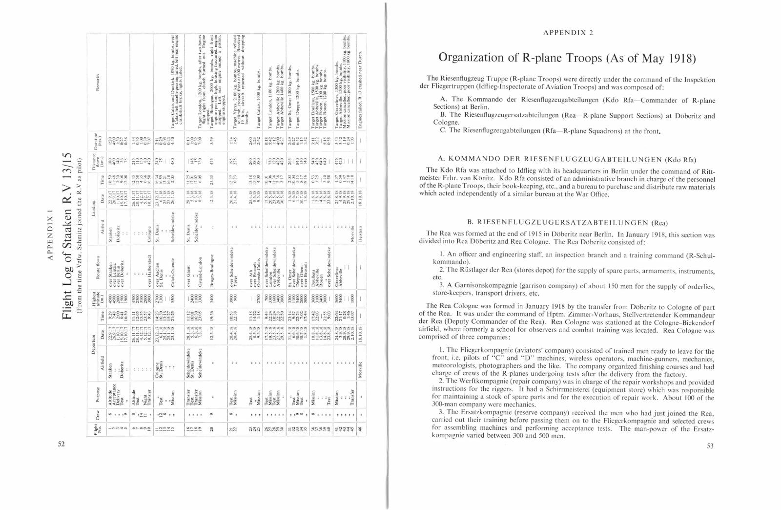
~ I;;~,., --
'"
I"''''.- ,,",N... -N
~ I~~,;.;N~ I~~,.,'" 1°-NN
; ;
TAPPENDIX 2
Organization of R-plane Troops (As of May 1918)
The Riesenflugzeug Truppe (R-plane Troops) were directly under the command of the Inspektionder Fliegertruppen (Idflieg-Inspectorate of Aviation Troops) and was composed of:
A. The Kommando der Riesenflugzeugabteilungen (Kdo Rfa-Commander of R-planeSections) at Berlin.
B. The Riesenflugzeugersatzabteilungen (Rea-R-plane Support Sections) at Daberitz andCologne.
C. The Riesenflugzeugabteilungen (Rfa-R-plane Squadrons) at the front.
A. KOMMANDO DER RIESENFLUGZEUGABTEILUNGEN (Kdo Rfa)
The Kdo Rfa was attached to Idflieg with its headquarters in Berlin under the command of Rittmeister Frhr. von Kanitz. Kdo Rfa consisted of an administrative branch in charge of the personnelof the R-plane Troops, their book-keeping, etc., and a bureau to purchase and di tribute raw materialswhich acted independently of a similar bureau at the War Office.
B. RIESENFLUGZE GERSATZABTEILU GE (Rea)
The Rea was formed at the end of 1915 in Daberitz near Berlin. In January 1918, this section wasdivided into Rea Daberitz and Rea Cologne. The Rea Daberitz consisted of:
I. An officer and engineering staff, an inspection branch and a training command (R-Schulkommando).
2. The Ri..istlager der Rea (stores depot) for the supply of spare parts, armaments, in truments,etc.
3. A Garnisonskompagnie (garrison company) of about 150 men for the supply of orderlies,store-keepers, transport drivers, etc.
:: =I =:::: I ::,,",00 =100 ; ;; ; I ::::; I ; I
"'''''''1-0'-00''"'°1-''''''''''''1-0'-00''"'°1-''''''''''''1-0 IMMM NMNN--=-- ~MMMM MMMM"'lf 'V"CtV~V V
52
co
~ ::~
5 100 ::;,,", 100 ;!= =1 ;~oo:: I::::_~~ I_N""""'I-o'-oo""'~I~~~!~ I~~~~
""'
°'"
100
;
I-N"'N----
: : :.::. ; ;; ; ; .!! I
_JI
The Rea Cologne was formed in January 1918 by the transfer from Daberitz to Cologne of partof the Rea. It was under the command of Hptm. Zimmer-Vorhaus, Stellvertretender Kommandeurdel' Rea (Deputy Commander of the Rea). Rea Cologne was stationed at the Cologne-Bickendorfairfield, where formerly a school for observers and combat training was located. Rea Cologne wascomprised of three companie :
I. The Fliegerkompagnie (aviators' company) consisted of trained men ready to leave for thefront, i.e. pilots of "C" and "D" machines, wireless operators, machine-gunner, mechanics,meteorologists, photographers and the like. The company organized finishing cour es and hadcharge of crews of the R-plane undergoing tests after the delivery from the factory.
2. The Werftkompagnie (repair company) was in charge of the repair workshops and providedin truction for the riggers. It had a Schirrmei terei (equipment store) which was responsiblefor maintaining a stock of spare parts and for the execution of repair work. About 100 of the300-man company were mechanics.
3. The Ersatzkompagnie (re erve company) received the men who had just joined the Rea,carried out their training before passing them on to the Fliegerkompagnie and selected crewsfor assembling machines and performing acceptance tests. The man-power of the Ersatzkompagnie varied between 300 and 500 men.
53
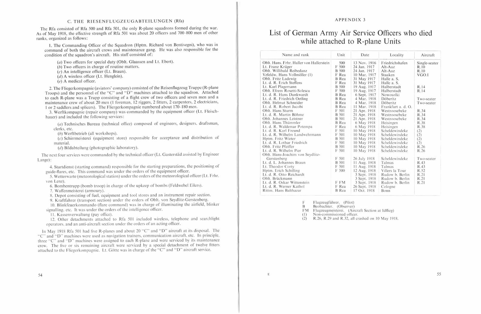
APPENDIX 3
List of German Army Air Service Officers who diedwhile attached to R-plane Units
F Flugzeugfiihrer. (Pilot)B Beobachter. (Observer)FM Flugzeugmeisterei. (Aircraft Section at Idftieg)(I) on-commissioned officer.(2) R.26, R.29 and R.32, all cra hed on 10 May 1918.
C. THE RIESENFLUGZEUGABTEILUNGEN (Rfa)
The Rfa consisted of Rfa 500 and Rfa 501, the only R-plane squadrons formed during the war.As of May 1918, the effective strength of Rfa 501 was about 20 officers and 700-800 men of otherranks, organized as follows:
1. The Commanding Officer of the Squadron (Hptm. Richard von Bentivegni), who was incommand of both the aircraft crews and maintenance gang. He was also responsible for thecondition of the squadron's aircraft. His staff consisted of:
(a) Two officers for special duty (Obit. Glaassen and Lt. Ebert).(b) Two officers in charge of routine matters.(c) An intelligence officer (Lt. Braun).(d) A wireless officer (Lt. Henglein).(e) A medical officer.
2. The Fliegerkompagnie (aviators' company) consisted of the Reisenflugzeug Truppe (R-planeTroops) and the personnel of the "C" and "D" machines attached to the squadron. Attachedto each R-plane was a Trupp consisting of a flight crew of two officers and seven men and amaintenance crew of about 20 men (1 foreman, 12 riggers, 2 fitters, 2 carpenters, 2 electricians,lor 2 saddlers and splicers). The Fliergerkompagnie numbered about 170-180 men.
3. Werftkompagnie (repair company) was commanded by the equipment officer (Lt. Flei chhauer) and included the following service :
(a) Technisches Bureau (technical office) composed of engineers, de igners. draftsman,clerk, etc.
(b) Werftbetrieb (all workshops).(c) Schirrmeisterei (equipment store) responsible for acceptance and distribution of
material.(d) Bildabteilung (photographic laboratory).
The next four services were commanded by the technical officer (Lt. Gasterstad a sisted by EngineerLange) :
4. Startdienst (starting command) responsible for the starting preparations, the positioning ofguide-flares, etc. This command was under the orders of the equipment officer.
5. Wetterwarte (meteorological station) under the orders of the meteorological officer (Lt. Frhr.von Lenz).
6. Bombentrupp (bomb troop) in charge of the upkeep of bombs (Feldwebel Eilers).7. Waffenmeisterei (armoury).8. Depot consisting of fuel, equipment and tool stores and an instrument repair section.9. Kraftfahrer (transport section) under the orders of ObIt. von Seydlitz-Gerstenberg.10. Blinkfeuerkommando (Aare command) was in charge of illuminating the airfield, blinker
signalling. etc. It was under the orders of the intelligence officer.II. Kassenverwaltung (pay office).12. Other detachment attached to Rfa 50 I included wirele s, telephone and earchlight
operator. and an anti-aircraft section under the orders of an acting officer.
In May 1918 Rfa 501 had five R-planes and about 20 "C" and "D" aircraft at its dispo al. The"C' and "0" machine were used a navigation trainers, communication aircraft. etc. In principle.three "C' and "'D" machine were assigned to each R-plane and were serviced by its maintenancecrew. The five or six remaining aircraft were serviced by a pecial detachment of twelve fittersattached to the Fliegerkompagnie. Lt. GeHte was in charge of the "C" and "0"' aircraft service.
Name and rank
Obit. Hans. Frhr. Haller von HallersteinLt. Franz KriigerObit. Willibald ReibedanzYzfeldw. Hans Vollm611er (I)ObIt. Fritz LadewigLt. d. R. Erich SteffensLt. Karl PlagemannObit. Efrem Rosetti-SolescuLt. d. R. Hans DankwardtLt. d. R. Friedrich OetlingObit. Helmut SchneiderLt. d. R. Robert JacobiObit. Hans SturmLt. d. R. Martin B6hmeObit. Johanne Leistner
IObit. Han ThiimmlerLt. d. R. Waldemar PotempaLt. d. R. Karl Freund
ILt. d. R. Wilhelm LandwehrmannHptm. Fritz WieterLt. d. R. Lothar FriedrichObit. Fritz PfeifferLt. d. R. Wilhelm PierObit. Hans-Joachim von Seydlilz-
Gersten bergLt. d. L. Johannes BraunLt. Theodor CortyHptm. Erich SchillingLt. d. R. Otto ReichardtObit. BriickmannLt. d. R. Oskar WittensteinLt. d. R. Werner KatholRittm. Hans Balthazar
Unit
500F 500B 500F ReaB ReaF ReaB 500F500B ReaB ReaB ReaB ReaF 501B 501B 501B ReaF ReaF 501F 501B 501F 501B 501F 501
F 501B 501F 501F 500
F FMF ReaB Rea
Date
13 ov.191624 Jan. 191724 Jan. 191710 Mar. 191731 May 191731 May 191719 Aug. 191719 Aug. 19176 Sept. J9174 Mar. 19184 Mar. 1918
I) Mar. 191821 Apr. 191821 Apr. 191821 Apr. 1918
6 May 19186 May 1918
10 May 191810 May 191810 May 191810 May 191810 May 191810 May 1918
26 July 1918I I Aug. 1918II Aug. 191812 Aug. 19183 Sept. 19183 Sept. 19183 Sept. 1918
26 Sept. 191817 Oct. 1918
Locality
I FriedrichshafenAlt-AuzAlt-AuzStaakenHalle a. S.Halle a. S.HalberstadtHalberstadtNowosolkiD6beritzD6beritzFrankfurt a. d. O.West roo ebekeWestroosebekeWestroosebekeHeisingenHeisingenScheldewindekeScheldewindekeScheldewi ndekeScheldewi ndekeScheldewi ndekeScheldewi ndeke
ScheldewindekeTalmasTalmasVillers la TourRudow b. BerlinRudow b. BerlinRudow b. BerlinCologneBonn
Aircraft
Single-seater IR.IOR.IOVGO.l
R.14R.14
Two-seaterTwo-seater
R.34R.34R.34R.38R.38(2)(2)(2)(2)R.26R.26
Two-seaterRA3RA3R.52R.21R.21R.21
54 E 55

57
~oUo
- ....'"
o:i
co
:h.0
il0.0.o.t;.0Eo.0
.S
oil'"
I~I
11u
"""" VlVlilJ QJ 0 ilJc: C c c:t':~ ((l~
0.0.. 0..0..a: a: a: a:
00
'"'"00
'5.0
'0
~~~ ~:sg t;~
"~'0
-0-,,--~
~.~
"5;z:
<i o:i
c c00'0'0C C00
...J...J
<i o:i
00o":~
o
·u>< C
-2:.:::..eOeil
.><'"00ONNOOI-
I
<i o:i
'0'0"" ~-~
~:s.". ....-00
oil.><
I~
II
'"'"
"co;z:
----- :-----'!---
~
c c "OOC'O'O~
gg~
1~~V1
'0C
":h'"o
.~
<i o:i I <i o:i I <i o:i <i o:i
._1__-
g f r > I g' ]u ~~ .:; ~ >. '-- 1) ~ ~ oo:..a c:~ ~~ ~~ ~ 00° oo:§ ~ilJ ~.~ ~ ~
~~ ~! ~~ ~ ~t ~~ i~ ;~ ~~ ~ ~~~<3. ~~ ~i 1 ~~ ~:f ~~ !; ~~ ~ E~~] ~E ~~ ~ ~'i ~~ ~~ ~~ ~.~ ~~~ ~ o~ N N Q ~ ~ ~.c r-- -- ~ ~::E; ~ ~gl~~ ~3 ~~I~ ~o ~~ ~~ ~£ ~i I~ ~u
- --- -_L-_...l..-_----'---_---.L_.L.-L-_...L.-_L-__--'------L._-----.l.~~__
c.:: 0
~ ~ ~~~v~ .8" ~-R_[i~ ~]10~0~~~~~ ~NMt"'1E ~ eUJ . .
~<iiO 1« Ol;z: ..«Ol
- --
APPENDIX 5
APPENDIX 4
Operational Missions of Rfa 501 (Eastern Front)
Statistical Comparison of Bombengeschwader 3 andRfa 501 during the England Raids
56
IBombengeschwader 3 Rfa 501 I
I
Total number of raids 22 II
Total weight of bombs dropped 84,745 kg. 27,190 kg.Percent of grand total (111,935 kg.) 75'7% 24'3%Number of aircraft which dropped bombs on England
I
292 28Average bomb load per aircraft 290 kg. 977 kg.
Total loaded weight of Gotha G.IY and Staaken R.YI 3,655 kg. 11,848 kg.Average bomb load as a percentage of total weight 7'96% 8'24%
Number of aircraft which took-off 383 30Number of aircraft completing mission 292 28Percent of aircraft completing mission 76-4% 93-4%
Number of aircraft lost to enemy actionI 24 0
Number of aircraft lost to accidentsI
37 2
Total number of aircraft lost I 61 2I
Percent of aircraft lost 15'9% 6·7%Average number of aircraft lost per raid I 2,78% 0·18
II I I
Bomb loadAircraft
IDate Target Location dropped (kg).
SSW R.6 3 Sept. 1916I
Railway station I Molodeczne UnknownSSW R.6 4 Sept. 1916 (3-hr. flight) 350SSW R.5 14/15 Oct. 1916 Railway station Wileyka 500SSW R.5 26 Nov. 1916 Troop camp Iza UnknownSSW R.5 7 Jan. 1917 Railway station Poloczany 325
i19Jan.1917 Troop camp Iza 712
SSW R.5 30 Jan. 1917 Railway station Wileyka 844SSW R.6 8 Feb. 1917 Railway station Molodeczne 373
12 Feb. 1917 Railway station Zalesie 550
SSW R.6 I 2 Mar. 1917 Railway station Zalesie and Molodeczne 590
SSW R.7 7 Mar. 1917 Railway station Wilekya and Molodeczne 590l 16 Mar. 1917 Troop camp Iza 560
{1 Apr.1917 Town Naracz 600
SSW R.4 5 Apr. 1917 Railway station Wileyka 600SSW R.6 5Junel917 Troop camp Biala 760SSW R.7 18 June 1917 Supply dump Overky 600
2 Aug. 1917 Railway station PrudyI
Reconnaissance
The following is an incomplete list of missions flown by Rfa 501 from Yilna as pieced together fromavailable documents:

APPENDIX 7 APPENDIX 8
Operational Missions of Rfa 500 and Rfa 501(Western Front)
List of known targets bombed by R-planes in France and Belgium as pieced together from availabledocuments.
Performance of R-planes on Combat MissionsDr.-Ing. Adolf Rohrbach, the designer of the Staaken £.4/20, compiled the following statistical
material on the combat missions flown by R-planes. He used these figures in 1920 to prepare astudy on the theoretical safety factor of multi-engined aircraft.
RECORD OF R-PLANE COMBAT MISSIONS
COMPILATION OF USEFUL LOAD VERSUS MISSIONS FLOWN
680 kg.
Duration I3 hr. 30 min-.-\2 hr. 27 min.3 hr. 10 min.3 hr. 48 min.5 hr. 40 min.4 hr. 35 min.6 hr. 40 min. 1
4 hr.
Weight of bombs
680 kg. I
30
Ceiling
2500 m.over 1900 m.over 3000 m.
3600 m.2900 m.3500 m.3300 m.1900 m.
2296 kg.2507 kg.3310 kg.4306 kg.4434 kg.4727 kg.4771 kg.4789 kg.
Usefulload
Useful load
b
Between 4400 kg. and 4600 kg.
Between 4000 kg. and 4200 kg.
Number of mission~1
Between 3850 kg. and 4000 kg. 12 l-I15
~B_et_w__e_el_l_42_0_0_k_g_._a_n_d_4_40_0_kg_. ~~ JI
Between 4600 kg. and 4700 kg. ==--=7 == !Between 4700 kg. and 4800 kg. 10 I
Type
SELECTED R-PLANE COMBAT MISSIONS(Showing increase in useful load during the war)
YGO.1I 9(15YGO.119(15YGO.lll 10(15Staak R.IY 12(15
I Staak R.IY 12(15Staak R. Y 13(15Staak R.Y 13(15Staak R.YI 31/16
East Front I
13 Aug. 1616 Aug. 1622 Sep. 16
9 Sep. 1718 Dec. 1725 Jan. 18
8 Mar. 181 July 18
Number of missions
Date
DFW
Type Location um er 0 ,Aircraft
IBegun Completed Not I Total I Ave./missionCompleted I
Staaken East Front 4
I21 18 3 15,485 kg. \ 860 kg.
West Front 16 102 94 8 103,932 kg. 1110 kg.
Total 20 I 123 112 II 119,417 kg. I 970 kg.
I I I 9,425 kg. II
Siemens East Front 4 23 20 3 470 kg. I
1 The R.13 war diary shows a duration from take-off to landing of seven hours.
Note: This chart does not show total missions flown.
Squadron Date Target
Rfa 501 Nov. 1917 DunkirkRfa 501 22/23 Dec. 1917 BoulogneRfa 501 25 Dec. 1917 BoulogneRfa 501 25/26 Jan. 1918 CalaisRfa 501 12/13 Mar. 1918 BoulogneRfa 501 20/21 Mar. 1918 I BoulogneRfa 501 1 Apr. 1918 BoulogneRfa 501 20/21 Apr. 1918 St. OmerRfa 501 7/8 May 1918 AbbevilleRfa 501 8/9 May 1918 CalaisRfa 501 9/10 May 1918 Dunkirk, CalaisRfa 501 23 May 1918 AbbevilleRfa 501 24 May 1918 BoulogneRfa 501 26 May 1918 AbbevilleRfa 501 27/28 May 1918 AbbevilleRfa 501 29/30 May 1918 AbbevilleRfa 500 30 May 1918 DunkirkRfa 500 31 May 1918 Creil, St. Just, CompiegneRfa 501 31 May 1918 Etaples, St. OmerRfa 500 I June 1918 MeauxRfa 500 1/2 June 1918 ParisRfa 501 5/6 June 1918 Boulogne, CalaisRfa 501 30 June 1918 Amiens, DieppeRfa 501 I July 1918 DieppeRfa 501 II July 1918 DoullensRfa 501 13 July 1918 ArrasRfa 501 15 July 1918 RouenRfa 501 30 July 1918 Ie HavreRfa 501 14Aug.1918 Ie Havre, Rouen, Abbeville IRfa 500 14 Aug. 1918 MeauxRfa 501 10/11 Aug. 1918 Doullens IRfa 500 11/12 Aug. 1918 BeauvaisRfa 501 11(12 Aug. 1918 Arras, AbbevilleRfa 501 13(14 Aug. 1918 RouenRfa 501 14(15 Aug. 1918 RouenRfa 501 16 Aug. 1918 RouenRfa 501 24/25 Aug. 1918 IGcave!;n"
IRfa 501 PoperingheRfa 501 4/5 Sept. 1918 AbbevilleRfa 500 15(16 Sept. 1918 Le Havre
.- -
5859

COMPILATION OF FLIGHT DURATION VERSUS MISSIONS FLOWN
Duration Number of Missions
..,CoZ
..,CoZ
..,Co NZ
..,CoZ
..,CoZ
..,.D
o
"0..,~
.~0)~
*
>,<..)C..,OIl......,E
lJ.l
00N
0::
..,c
'gnc..,2
>,e<lE
..cU
>><0::
..,:J
"0OIlC
"0
~ E"0C~
:c.~
z
>,.D
C~o
"0
o..cen
C"0 "00' ..,
en ..cV>e<l....<..)
000000V) V) V)
~ ~ ~0:: 0:: e:::
1l-I-
C "0"0 ..,0' ..c
en ~....<..)
"0Ce<l
"0..,00-
Vi<>
"0Vi
>,.D
C~o"0
o..cen
-<-<
"0..,<..)....o
IJ"
>, .D
OIlC
"0Ce<l
~.DEo<..)
OIlC
"0C~OIlo
IJ"
.~..,"00)
I~I
OIl>, Cg "0
~ E.., OIlE 0
UJ IJ"
>,......,.~0)"0CoOIlC
"0C~
>,<..)C..,OIl......,E
lJ.l
*
..,::l
"0OIlC
"0C~>,<..)C
~......,E
UJ
OIlC
"0C~
co..,....:J
Co....
IJ"
E..,';/le<l
UJ
~
oCJ>
1
II~
Co
V>V>o
e<l<..)
o...l
~-~- - ---- --+--+----+--+--'---,--.,-----'--i---+--+--c---;----I 1 I
o 0 0\810 8~ ~ ~ ~I~ ~_~_~ ~ I~ I~ ~_
~I~ 1.., ..,"0 .DC ..,.~ 0.., 0 V>"0.... e<l~ IJ'l N E
~I; ;gl~
- --] -- .~ ------1-1-1-1-1-~ c eo "':J<..)
~ 2 3o ..,C :JV> "0
C OIlo '§.2~ ~ c:g ~e<l
.bC
S
3
8
8
9
4
8
4
3
21
20
20
33
Total number of failures
Fuel system
Instrument failure
Enemy action
Engines
Radiators
Reduction gears
Between 7 and 8 hr.
Between 3 and 4 hr.
Between 5 and 6 hr.
Between 6 and 7 hr.
Between 4 and 5 hr.
Between 2t and 3 hr.
Type of failure
Between 3600 m. and 4000 m. 5
Between 4000 m. and -
Greatest Duration 7 hr. 50 min.
Altitude Number of missions
Between 1600 m. and 2000 m. 4
Between 2000 m. and 2400 m. II
Between 2400 m. and 2800 m. 24
Between 2800 m. and 3200 m. 30
Between 3200 m. and 3600 m. 16
COMPILATION OF ALTITUDE VERSUS MISSIONS FLOWN
TYPES OF FAILURES EXPERIENCED ON 110 COMBAT MISSIONS OFRFA 501 FLYING STAAKEN R-PLANES
Note: Out of twenty-one of eighty-eight completed We tern Front missions, one engine failed or had to bestopped without being able to start it again during mission. On five of these twenty-one missions enginestoppage occurred on the outward-bound flight. On six other missions it was possible to repair severe enginedefects such as cooling system damage, fuel line ruptures, valve and ignition failures. These defects eitherstopped or would have stopped the engine, but in-flight repairs made it possible to run the engine for theremainder of the mission. On three other missions the engine failed after repairs had been performed.
60 6I

Estimatedcompletion
date
31 Jan. 191931 Jan. 1919
15 Feb. 191915 Mar. 1919
31 Jan. 191915 Mar. 1919
31 Jan. 191915 Feb. 1919
I 15 Mar. 191915 Apr. 191915 Apr. 1919
ca. 25,000ca. 50,000
ca. 10,000
ca. 2,000ca. 18,000
ca. 150,000
ca. 100,000ca. 125/150,000
ca. 200,000
Cost required tocomplete aircraft
(marks)
Ready for flightReady for delivery
Status on 15 Jan. 1919
Assembly t completeAssembly t complete
Almost completedAlmost completed
Assembly t completeAssembly 1- complete1ndividual parts complete. I
Assembly begun
IReady for flightAssembly complete
450,000450,000
530,000530,000
600,000600,000600,000
500,000500,000
750,000750,000
Total cost(marks)
Linke-HojinannR.55R.56
Schiitle-LanzR.84R.85R.86
Constructor andaircraft
APPENDIX 11
Staaken R.XVI(Av) 50/17, one of the R-planes completed after 31 January 1919, with company markings.
A viafikR.50R.51
DFWR.18R.19
Siemens-SchuckertR.23R.24
List of R-planes to be Completed after 31 January 1919
IIIIrIt-
V)
~
II
I I I
I I II I I
I II I--1-1 1-
1 \D I I M I II"<:t j v: I~ I I ~ I I
I I I
IINM\D
1000N N N
1
0202C::
I-=-I~
I~
I~~ II~~ I
1-:- I\D
~
0\
(l)
C:J-.
0..(l)
C/)
uo
....a.
-<
I 1_ I II I v: 1 I
II ~ I I
I I i I-i-----i-I ---11---:1-------:--1 -'-I
II 1 0 1 I
I v: I I
II ~ I I
--+---+-----+-------'---;------,--1~I-T---I I I I I I I~ ~ ~ I~ I
~ ~ I I~ I
~I~~I~I~~ I l~i ic::c:: ~I~~ I I~I I
o-
62 63

To overcome the shortcomings of the inaccurate Carbonit bomb, the Prufanstalt und Werft derFliegertruppe (P.u.W.-Test Establishment and Work hop of the Aviati?n Troops) and the opticalfirm of Goerz-Friedenau, a manufacturer of bomb-sights, co-operated III 1915 to develop the s~
called P.u.W. bomb. Thi torpedo-like bomb had a superior aerodynamic performance and IS
considered by armament expert to be the true prototype of the modern aircraft bomb. It was manufactured from high-grade steel, rather than cast-iron, which gave it supenor penetration power. and
65
German P.u.W. high-explosive aerial bombs.
In order to obtain a more effective weapon, experiments were performed which resulted in aseries of bombs known as the Carbonit (or Karbonit) type, produced by Sprengstoff A.G. "Carbonit"Schlebusch. This series of bombs had a tear-drop-shaped cast-iron body, a steel-tipped nose forbetter penetration, a ring-shaped stabilizing fin and a propeller-activated tail fuse. The ~arbonit
bomb, generally loaded with T T, was produced in 4·5 kg., 10 kg., 20 kg. and 50 kg. sizes. Allearly R-planes were fitted to carry these bombs hung vertically in the bomb b.ay. .
The Carbonit incendiary bomb was constructed from a blunt-nosed cylllldncal sheet-steel contalllerfitted with a tail fuse and a circular stabilizing fin. It was filled with a highly inflammable mixtureconsisting of one part benzol or petrol, five parts kerosene and a sm.all qu~ntity ?f liquid tar. Thetotal weight of the bomb was 10 kg., of which 3·5 kg. represented the IIlcendlary mixture. Due to thehighly inflammable nature of the bomb, it was always filled shortly before take-o.ff.
The Carbonit bombs were used by the Germans from the end of 1914 until 1916; although animprovement over the A.P.K. bomb, they oscillated too long after release and had a tendency to driftwith the wind.
Another incendiary weapon which found use in the early years of the war was the Goldsch.midtbomb. Filled with a mixture of benzol, tar and thermite, this incendiary burned at the then exceedlllglyhigh temperature of 3000° C. This weapon, very similar in shap~ to the Carbonit b~mb, consist.edof an inner iron cylinder filled with thermite, surrounded by a thlll sheet metal contalne~ filled With3·5 litres of benzol; the outer shell was wrapped with tarred rope, which prevented dIspersIon ofthe benzol. Its total weight was about 10 kg.
4-·5 kg-10 kg.
CARBONIT H.E. BOMBS
20 kg.50 kg.
Short Description of German Bombs
APPENDIX 12
The first German bomb specifically intended for aircraft use was known as the A.P.K. bomb, sonamed after the Artillerie-PrUfungs-Kommission (Artillery-Test Commission), the Army departmentwhich had originated this weapon. The A.P.K. bomb consisted simply of a circular cast-iron shelland an impact fuse. It was filled with high explosive and was produced in 5 kg. and 10 kg. sizes.The A.P.K. bomb, developed in 19]2/13, was not used in the war.
64

.....,
3C
0(JQ
C~
:l
~[
ri~
(j)....
..
........
...::
r::
r(j)
(j).....
,.....
.C
~V
l_
.
(j)-
V>~
o-:
:J'<
V>
():E
(j)(j)
:l.,
......
(j) ~ ::J...,~
::r:
:J(j
)(JQ
"C~
i::....
...
0~Vl
.'g
.o
-:l
oI
3~
o-~
C/)
=-=:E
N'
(j)(j)
.,.....
.(j)
::r
()(j)
o0
:l
0q.
3C
0
~o..
(j)C
0..
::;.
-':
l:l
(JQ
Vl
_.
><'(
i;"0
..::
;_.~
~~.
(j)(j)
.,()
(j)....
.:l
0.....
..,
v>
'<_.~
N:l
~0.
.~
......
V>
0
O'~
-.....
0"<'
:E~
V>~
~C/) ." I'T1
(J ,..., .,., ,.....
(J ;> ,.., o C/) .,., o ;::0 ." c to o 3::: IJ:I
C/)
~ (1)
(JQ ::r ..... o ~. 3 ~ (1
) ., t- (1)
:J ~ ::r
I I I I
0" .....,
Zc
0c
~...
..,3
V>
0"
(1) .,
:3 3;.;
f!<I
::J 0'"
CTI
....
.,(1
):;
:><
~"'"'1("O""O
o()
_.
....
.(1
)(J
q0
~_::ren
_.-I~_.
.....
< (1)
10
OW
O
OO
Vl-
00
00
10
10
Vl
Vl
*
10
10
0'1
10
0
0'1
10
-1
01
0V
l-O
O-J-J
OV
,V,N
V,V
,O
OO
VlO
lOl
VlW
N-
VlO
lVlo
o-l
>-\
DO
VlO
OO
O
N
--I>
-\D
-JV
lW......
OIW
oo
OV
lVl
Vl-
J-I>
-\D
--I>
-
-1>
-10
-...
....
1:3
O-J\D
-JO
O-J
:3O
VlO
OV
lVl
VlO
OO
OO
VlO
-JO
IW
N-J
oo
-l>
-OIW
\DI
::Jci\
N0
00
.i.v
,O
O-JO
W-JW
0'1
0'1
0'1
-1>
0
00
00
'1
10
10
10
---
* ..... ::J ()
(1)
::J 0..~ ., '<
0..
0.. < ~ ., '< '< 0' ., 0.. ~ ., (1)
::J
o 3l () ~ :;; 2: (1)
en 0"
C ..... en ciCi'
::r .....en N (1)
en ~ ::J 0.. :;: (1)
ciCi'
::r ..... en
~"O~
(3,.
.,0
..::
rc
(1)
()
V>
:::-
'"0
o(1
)
::Jr2
..,
::nc
()='
g. o ::J en ~ 0" o < (1)
~ f1i ::;> o :3
....:.
:<J
c ~ OJ
o 3:
OJl.u o C)
AU
)
~0'
.,.,
::;.rp
;l>2.~:::
_.
5-
"C:l
'i::
Vl~
•
'0;::;
>~
(j)()
•Q.~
0
:::..~o
3~
3~~Sf
~0
:EN
3(j)
5'~
@(j) ~Vl
~.
::r
(j)3
~~
'0_
.()
_N
::r(j)o
.,:l
::r(
j)....
..o
()~
o:S~
_.
:l:l
(JQV
l(JQ
CC
~.~-o
;><.,
(j)
0-:
:;>
5-
o~
(j)3
;30.
.0
-(j)
_.
en_.
::s
:l....
......
..::
r::
r(j)
(j)0
0
-0
o3
30
0
-0
O"~
~'<
'<~.
......
...
.,~
::r
(j)
~
Vl
.,
3~
~.,
:::
0
.......
0N
30
,0-
Vl
~:E
•(j)
0-"
o(j)
3::
r0
-5
:E(J
Q~
0"
Vl'
<
c;;0 O? V1 o o (J
Q <3 c :J 0
() .., () :;: <: 0 o 3 0-o ~ 0-
:J (JQ ~ w o o ""(JQ "
0\
0\
AP
PE
ND
IX13
Cha
rtof
R-p
lane
Num
bers
,D
imen
sion
san
dPe
rfor
man
ceA
RM
YA
IRC
RA
FT
----
------
II
II
Sp
anIL
engt
hIA
rea
(sq.
Em
ply
ILoa
ded
Spe
edT
ype
To
tal
h.p.
Tra
clo
rP
ushe
r(m
etre
s)~metres)
met
res)~~
(k.p~
Bl.
III
450
2-
2817
·513
84.
000
5.20
011
0D
.IV
a78
02
-38
18·5
233
6.15
08.
460
110
B/.
IV66
02
-34
·33
17·7
177
5.40
06.
820
132
Bz.
IV66
02
-3
76
1820
15.
450
6.90
013
0B
z.IV
660
2-
34·3
317
·717
75.
300
6.76
613
2B
z.IV
660
2-
33·3
617
·717
15.
250
6.80
013
2D
.IV
aI
780
2-
38·4
418
·521
05.
700
7.96
013
0D
.IV
a10
402
-I
32·0
215
'56
264
I5.
800
9.00
014
0H
S72
01
24
2·2
23·7
833
26.
637
10.2
0311
00.
111
960
12
42
·224
·533
28.
600
11,6
0012
0D
.IV
880
22
29·5
17·6
182
5.65
28.
380
120
~~.II~
}12
00I
24
22
I23
·233
2I
8.77
213
.035
125
Mb
.IV
aI
1225
3-
I4
2·2
2333
29.
450
13,0
1013
5~~.III~
}12
00I
24
2·2
22'1
332
8.92
312
,953
130
D.I
Va
1040
22
35·0
620
·93
266
8.63
411
.693
135
D.I
Va
1040
22
35·0
620
·93
266
9.03
212
.642
-D
.IV
aI
1040
22
35
'06
20·9
326
68.
634
11.6
9313
5D
.IV
a10
402
23
5'0
620
·93
266
8.63
411
.693
135
D.I
Va
1040
22
35'0
620
·93
266
8,63
411
.693
135
D.I
Va
I10
402
235
·06
20·9
326
68.
634
11.6
9313
5D
.IV
a10
402
-I
3619
'526
09.
000
12.7
00D
.IV
a10
402
-36
19'5
260
9.00
012
.700
BuS
.1V
1800
22
4821
·644
010
.500
15,9
0012
5B
uS.I
V18
002
248
21·6
440
10.5
0015
.900
125
D.I
Va
1040
22
42
·222
'133
27.
680
11.4
6013
0D
.IV
a10
402
24
2·2
22'1
332
7.68
011
.460
130
D.I
Va
1040
22
42
·222
'133
27
.68
01
1.4
1>
013
0M
b.I
Va
980
22
42
·222
'133
27.
921
11,8
4813
5M
b.I
Va
980
22
42'1
22'1
332
7.92
111
.848
135
D.I
Va
1040
22
42
'222
'133
28.
600
11.5
9016
0D
.IV
a10
402
242
·222
'133
27.
680
11.4
6013
0M
b.IV
a98
02
242
·22
2,'
332
7.92
111
.848
135
D.I
Va
1040
22
42
'222
'133
27.
680
11,4
6013
0D
.IV
a10
402
24
2'2
22'1
332
7.68
011
.460
130
D.I
Va
1040
22
42
'222
'133
29.
300
12,8
7513
0D
.IV
a10
402
24
2'2
22'1
332
7.68
011
.460
130
Mb.
IVa
980
22
42
222
'133
27.
921
11,8
4813
5D
.IV
a10
402
242
·222
'133
27.
680
11.4
6013
0M
b.IV
a98
02
24
2·2
22'1
332
7.92
111
,848
135
D.I
Va
1040
2-
33·2
15·6
265
8.00
011
.200
130
D.I
Va
1040
2-
33·2
15·6
265
8.00
011
.200
130
D.I
Va
1040
2-
33·2
15·6
265
8,00
011
.200
130
Mb.
IVa
1225
32
42
·22
2'5
334
10.3
5014
.450
130
Mb
.IV
a12
253
24
2·2
22
'533
410
.350
14.4
5013
0M
b.I
Va
1225
32
42
·22
2'5
334
10.3
5014
,450
130
Mb
.IV
a12
253
24
2·2
22·5
334
Mb.
IVa
1225
3I
242
·222
·533
4M
b.IV
a12
25_
32
42·2
22
'5_
1~
_
Fac
tory
Typ
eN
o.ISe
rial
No..
Lic
ence
IN
o.IM
anuf
actu
rer
-----------
SS
WR
.IR
.I/1
5-
3B
enz
SS
WR
.II
R.2
/15
-3
Mer
ced
esS
SW
R.I
IIIR
.3/1
5-
3B
enz
SS
WR
.IV
R.4
/15
3B
enz
SS
WR
.VR
.5/1
5-
3B
enz
ISS
WR
.VI
R.6
/15
3B
enz
SS
WR
.VII
IR.7
/15
3M
erce
des
Li-
I-fo
R.I
R.8
15
4M
erce
des
VG
OV
GO
.II
R.9
/15
-3
May
bach
VG
OV
GO
.III
R.1
0/15
-6
Mer
ced
esD
rWR
.IR
.II/
15
-4
Mer
ced
es
S"'
akR
.IV
R.1
215
-6
{2
Mer
ced
es4
Ben
zS
laak
R.V
R.1
3/15
-5
May
bac
h
Sla
akR
.VII
R.1
4/15
-6
{2
Mer
ced
es4
Ben
zD
FW
R.I
IR
.15/
16-
4M
erce
des
DF
WR
.II
R.1
6·16
4M
erce
des
DF
WR
.II
R.1
7/16
4M
erce
de-
;D
FW
R.I
IR
.18/
164
Mer
ced
esD
FW
R.I
IR
.19/
16-
4M
erce
deo;
;;D
rWR
.II
R.2
0/16
-4
Mer
cede
;;A
EG
R.I
R.2
1/16
-4
Mer
ced
e\A
EG
R.I
R.2
2/16
4M
erce
del
\S
SW
R.V
III
R.2
3/16
-6
Bas
se&
Sel
veS
SW
R.V
III
R.2
4/16
-6
Bas
se&
Scl
vcS
taak
R.V
IR
.25/
16-
I
4M
erce
des
Sta
akR
.VI
R.2
6/16
4M
erce
des
Sta
akR
.VI
R.2
7/16
Sche
ll4
Mer
ced
esS
taak
R.V
IR
.28/
16Sc
hUl
4M
ayb
ach
Sta
akR
.VI
R.2
9/!
6Sc
hUl
4M
ayb
ach
Sta
akR
.VI
R.3
0/16
-4
Mer
ced
es
ISta
akR
.VI
R.3
1/16
-4
Mer
ced
esS
taak
R.V
IR
.32/
16-
4M
ayb
ach
Sta
akR
.VI
R.3
3/16
Av
4M
erce
des
Sta
akR
.VI
R.3
4/16
Av
4M
erce
des
Sta
akR
.VI
R.3
5/16
Av
4M
erce
des
Sta
akR
.VI
R.3
6/16
IAlb
s
I
4M
erce
des
Sta
akR
.VI
R.3
7/16
Alb
s4
May
bac
hS
taak
R.V
!R
.38/
16A
lbs
4M
erce
des
Sta
akR
.V!
R.3
9/16
4M
ayb
ach
Li-
Ho
R.I
R.4
0/16
-4
Mer
ced
cl\
Li·
lfo
R.I
R.4
I/1
6-
I4
Mer
ced
esL
i-H
oR
.IR
.42/
16-
4M
erce
des
Sta
a,
R.X
IVR
.43/
175
May
bac
hS
taak
R.X
IVR
.44/
175
May
bac
h
ISta
akR
.XIV
R.4
5;17
-5
May
bac
hS
taak
R.X
VR
.46
17-
5M
ayba
chS
laak
R.X
VR
.47/
17-
5M
ayba
chS
laak
R.X
VR
.48/
175
May
bac
h
0\
-..l
Des
ign
atio
nE
ngi
nes
Pro
pel
lers
Dim
ensi
ons
Wei
ghts
Per
form
ance
IC
lim
bC
eili
ng(m
etre
s)(m
inu
tes)
(met
res)
2000
3537
0030
0045
3800
2000
3530
0030
0010
430
5030
0010
230
0020
0036
2950
3000
66
I
3200
2000
25-
2000
3930
0030
0056
3000
--
-30
0089
3700
3000
3445
00
3000
5038
5020
0058
--
-20
0058
-20
0058
-20
0058
-20
0058
--
--
--
--
-40
00-
-40
0030
0055
3800
3000
5538
0030
0055
3800
3000
4343
2030
0043
4320
3000
3559
0030
0055
3800
3000
4343
2030
0055
3800
3000
5538
0030
0055
3800
3000
5538
0030
0043
4320
3000
5538
0030
0043
7420
3000
120
-30
0012
0-
3000
120
-30
0070
3700
3000
7037
0030
0070
3700
--
--
--
--
-
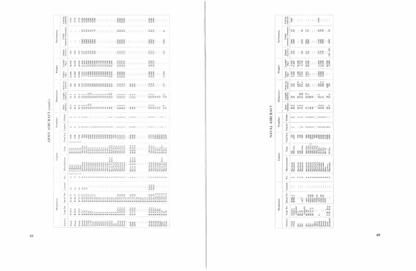
0\
00
AR
MY
AIR
CR
AF
T(c
oli/d
.)
Des
ign
atio
nEngine~
Pro
pel
lers
Dim
ensi
ons
Wei
gh
tsP
erro
rman
ce
"aC
lOry
IT
yp
eN
o.
ISer
ial
No
.L
icen
ceN
o.
Man
ufa
ctu
rer
II
Sp
anT
ota
lh
.p.
Tra
cto
rP
ush
er(m
etre
s)
------~-----
Len
gth
IAre
a(s
q.I
Em
pty
ILo
aded
ISp
eed
(met
res)
met
res)
(kg
.)(k
g.)
(k.p
.h.)
-------,--------
37
10
37
10
37
10
43
20
43
20
43
20
32
00
32
00
5200
5200
45
00
45
00
45
00
45
00
4500
45
00
45
00
43 43 43 45 45 76 76 45 45 45 4145 45 45 45
30
00
3000
30
00
30
00
30
00
50
00
50
00
30
00
30
00
30
00
30
00
30
00
30
00
30
00
30
00C
lim
bC
eilin
g(m
etre
s)(m
inu
tes)
(mel
res)
135
135
135
145
130
130
130
135
135
135
130
130
180
180
135
135
135
135
14.2
5014
.250
14,2
50
14.6
50
14,6
50
14,6
50
11,8
4811
.848
11,8
4812
.000
12.0
0010
.000
10.0
0012
.700
12.7
0012
,700
12.7
0012
,700
12.7
0016
.600
16,6
00
14.2
5014
.250
14,2
5014
,250
10.0
0010
,000
10,0
00
12.4
80
10.4
00
10.4
00
10.4
00
7,92
17,
921
7,92
18
.00
08
,00
06
,00
06
,00
09
,00
09
,00
09
,00
09
,00
09
,00
09
,00
010
,860
10,8
60
10.0
0010
.000
10,0
0010
.000
325
334
334
334
34
0
34
0
34
0
332
332
332
320
320
20
020
026
026
02
60
260
26
026
04
10
41
0
334
334
334
334
44
04
40
44
0
22
·52
2'5
22
'530 30 3022
·5
21·6
21
·62
1·6
24·2
3022
'52
2'5
22·5
22
·5
22
5
22
5
22
12
21
22
12
0·3
2W
32
22
32
23
19·5
19·5
19·5
19·5
19·5
19·5
22
·97
22
·97
42
·2
42
·24
2·2
42
·255 55 55 45
'95542
·2
42
·24
2·2
42
·24
2·1
64
2'1
635 35 3
6 36 36
36
36
36
44
44 48 48 4842
·2
42
·24
2·2
42
·24
2·2
2 2 22
2 2 2 1 I 2 2 2 2 2 2 2 2 22 2 2 2
1800
1800
1800
1225
1225
1225
2080
20
80
2080
2400
2800
28
00
1500
1500
1500
98
09
80
98
010
4010
4010
4010
4010
4010
4010
4010
4010
4010
4018
0018
009
80
98
012
2512
2512
2512
25
Ty
pe
Ru
S.I
Va
Bu
S.I
Va
BuS
.1V
a
BL
.IV
RL
.VI
B'.
IV13
'.VI
BL
.IV
B'.
VI
Mb
.IV
aM
b.I
Va
Mb
.IV
aD
.IV
aD
.IV
aD
.IV
aD
.I\·
aD
.IV
aD
.IV
aD
.IV
aD
.IV
aD
.IV
aD
.IV
aB
uS
.IV
aB
uS
.IV
aM
b.I
Va
Mb
.IV
aM
b.I
Va
Mb
.IV
aM
b.I
Va
Mb
.IV
a
-Mb
.IV
aM
b.I
Va
Mb
.IV
aD
.IV
aD
.IV
aD
.IV
aB
uS
.IV
aD
.IV
aD
.IV
a
2B
enz
2B
enz
2B
,nz
2B
enz
2B
enz
2B
enz
May
bac
hM
ayb
ach
May
bac
hM
erce
des
Mer
ced
esM
crce
de<
;Mcrcede~
Mer
ced
esMercedc~
Mer
ced
esM
erce
des
Mer
cedc
!o>
Mer
ced
esB
asse
&S
clvc
Bas
se&
Scl
vcM
ayb
ach
May
bac
hM
ayb
ach
May
bac
hM
ayb
ach
May
bac
h
Bas
se&
Se
lvc
Bas
se&
Sel
veB
asse
&S
clvc
May
bac
hM
ayb
ach
May
bac
hM
erce
des
M~rcedes
Mer
ced
esB
asse
&S
chc
M::
rced
csM
erce
dc'
i
6 6 6
{ {4
{
:I
4 4 4 4 4 4 4 4 4 4 6 6 4 4 5 5 5 5
A\
A\
Av
Av
A\
A\
Sch
ul
Sch
ul
Sch
ul
R.4
917
R.5
017
R.5
1/1
7
R.5
2/1
7R
.53
/17
R5
4/1
7R
.55
/17
R.5
6/1
7R
.57
17R
.58
17R
.59
R.6
0R
.61
R.6
2R
.63
R.6
4R
.65
R.6
6R
.67
R.6
8R
.69
18R
.70
18R
.71
/18
R.7
2/1
8R
.73
R.7
4R
.75
.18
R.7
618
R.7
7/1
8R
.78
R.7
9R
.80
R.8
1R
.82
IC~3
R.8
4/1
8R
.85
/18
R.8
6/1
8R
.201
16R
.20
216
R.2
03
/ln
R.2
04
16R
.20
516
R.2
06
In
R.V
llla
R.V
llla
R.V
llla
R.X
VI
R.X
VI
R.V
IR
.VI
R.V
IR
.II
R.I
IR
.IR
.IR
.IR
.IR
.IR
.IR
.IR
.IR
.IR
.IR
.IR
.IR
.XIV
aR
.XIV
aR
.XIV
aR
.XIV
a
R.X
VI
R.X
IVa
R.X
IVa
R.X
IVa
R.V
III
R.V
III
R.V
III
R.I
XR
.II
R.I
X
Sla
ak
Sta
ak
Slaa
kS
taa
k5
wa
kL
i-H
oL
i-H
oJu
nk
Jun
kA
EG
AE
GA
EG
AE
GA
EG
AE
GS
chu
lS
chu
lD
oD
oS
taak
Sta
akS
taak
Sta
ak
Sla
ak
I· ~~~
SS~
ISta~
Sta
akS
taak
Sta
akS
taak
Sta
akS
SW
AE
GS
taak
__
_I
NA
VA
LA
IRC
RA
FT
Des
ign
atio
nE
ng
ines
Pro
pel
lers
Dim
ensi
ons
Wei
ghts
Per
form
ance
25
00
30
00
80
50 35 53 60 54 54
1780
30
00
30
00
30
00
20
00
30
00
25
00
2000
20
00
125
UO
130
110
130
128
135
138
12
8-1
40
Sp
eedI
Cli
mb
ICei
lin
g(k
.p.h
.)(m
etre
s)(m
inu
tes)
_(m
etre
s)
I1,
800
12,5
0012
,500
48
:00
0I
12,0
00
8,4
00
9,0
00
9.0
00
360
34
0'5
34
0'5
1000
35
038 2
2·8
22
·221 21
80
42
'7
42
·24
2·2
42
·2
2 2 2 2
2 2 2 2 4 2
4 4 4 8 4 4 4 4 4 4 4 4
RM
L.I
RM
L.I
1433
Ser
ial
No
.T
yp
eN
o.
Fac
tory
VG
OV
GO
Lic
ence
INo
.M
anu
fact
ure
rI
Ty
pe
TO
lal
h.p
.T
ract
or
Pu
sher
Sp
anL
eng
thA
rea
(sq
.E
mp
tyL
oad
ed(m
etre
s)(m
etre
s)m
etre
s)(k
g.)
(kg
.),-
---1
I--
------------------------
-I
3M
ayb
ach
HS
72
0I
24
2·2
2433
26
,52
09
,52
0-
5M
ayb
ach
Mb
.IV
a12
25I
24
2·2
243
20
7,4
50
11,4
85
3M
ayb
ach
HS
72
03
43
'529
32
8·8
7,5
00
10,5
003
May
bac
hH
S7
20
33
3·2
23
·88
257
I6
,47
57
,32
34
May
bac
hM
b.I
Va
98
02
23
3·2
23
·88
I2
34
·37,
278
9,1
58
May
bac
hM
b.I
Va
98
02
237
22
·75
226
I7,
865
10,6
70M
ayb
ach
Mb
.IV
a9
80
22
372
2·3
226
I7,
237
I10
.600
May
bac
hM
b.V
I(?
)2
40
02
24
428
May
bac
hM
b.I
Va
1960
22
44
30
May
bac
hM
b.I
Va
98
0M
ayb
ach
Mb.
1V
a9
80
Mer
ced
esD
.IV
a10
40M
erce
des
D.I
Va
1040
Mer
ced
esID
.IV
a10
40B
enz
Bz.
VI
21
20
Jun
ker
s-
40
00
Mer
ced
esD
.IV
a10
40
..--_
..:.
.._
-----:_
--_
--.:
..-_
_--..:.-_-~_---.:..._
_..:...-_--.:~
0\
'-0

APPENDIX 14
Sikorsky "Ilia Mourumetz"
The world's first four-engined aeroplane, designed by the Russian, Igor Sikorsky, had a greatinfluence on the aeronautical community throughout the world. The early "Le Grand" and "RusskiiVitiaz" machines visibly demonstrated that it was possible to operate four engines in unison and thata large aircraft could be readily controlled in flight. As stated in the Introduction, here was the truepromise of flight: a vehicle to conquer long distances at high speeds in relative safety. Because of theinfluence of the Sikorsky "giants", particularly the "Jlia Mourumetz" bombers, a short descriptionof the latter is included in this book.
Developed from Igor Sikorsky's record-breaking "Le Grand" and "Russkii Vitiaz" passengercarrying machines of J913, the slightly larger"Jlia Mourumetz" was flown for the first time inJanuary 1914. In the summer of that year the Russian Army placed an order for ten machines of the"Jlia Mourumetz" class.!
Sikorsky I.M. B (E.V.K. aircraft number VI), at Yablonna in December 1914.
The first operational bomber (actually the second one built) was completed in the spring of 1914.On 15 February 1915 the "Kievsky", as the machine was named, took-off from Jablonna airfield tobomb German forces stationed near Plotsk. On this, its first operational mission, it carried a crewof five and bomb load of 600 kg. Nine days later it bombed the railroad station at Willenberg,returning the next day to destroy two ammunition trains detained by the previous day's attack.
As more "Jlia Mourumetz" class bombers reached active service, they were grouped into aspecial squadron known as the E.V.K. (Eskadra Vozdushryh Kovablei). This squadron moved fromone front sector to another as required, several additional E.V.K. squadrons were formed as thenumber of available bombers increased. During 1916 as many as ten bombers would fly on a singlemission, and an even greater number in 1917. Available records for the first sixteen operational"Jlia Mourumetz" bombers state that they flew 422 sorties between February 1914 and October 1917.A total of 2300 bombs were dropped and 7000 aerial photographs were taken during this period.
The ruggedness of these bombers must have impressed the Germans who met them in combat.The bombers were quite difficult to shoot down; one machine returned to base with 374 shrapneland bullet holes and one wing strut shot away. Other aircraft returned safely with one or two enginesout of action. The crews of the "Ilia Mourumetz" could also hit back if their claim for thirty-sevenenemy aircraft shot down is correct.
Of the seventy-three "Jlia Mourumetz" class bombers constructed, about half were used at the
Sikorsky I.M. V, one of several aircraft that bore the name "Kicvsky". Igor Sikorsky is seen second from the right.
front; the remainder were placed into service primarily as trainers. In thirty-two months of activeservice only four bombers were lost: two through enemy action, one spun into the ground, and onewas lost as a result of Bolshevik sabotage. With the disintegration of the Russian Front at the timeof the revolution many of the "Jlia Mourumetz" bombers were destroyed to prevent their captureby the Germans. It is claimed that thirty machines were burned by their own crews at the Yinnitzairfield.
The "Ilia Mourumetz" bombers had a span of about 31·1 metres (102 feet), a wing area of 158square metres (1700 quare feet) and an overall length of 20·2 metres (66 feet 3 inche). The moststriking characteristic was the small amount of fuselage projecting ahead of the wings, giving thebombers a sawn-off appearance. Production was undertaken by the Russo-Baltic Wagon Works inRiga. The ba ic design was progressively modified; for instance, the original machine was providedwith four German 120 h.p. Argus engine, but later type were fitted with British and French enginestotalling 880 h.p. Similarly, wing area and weight were increased. The total weight of later typeswas 17,000 lb., of which 6600 lb. wa useful load. The "Ilia Mourumetz" bombers were the first tohave a tail-gun position, which the gunner reached by riding a trolley on rails running along the insideof the fuselage. At least one "Jlia Mourumetz" wa fitted with floats for tests with the Russian avy.
1 "Ilia Mourumetz", a legendary Russian hero, was the name given to the first machine only, but later it was usedto designate the whole series and each machine was given a number, i.e., IM.IX, IM.xIV.
70 F 71

PART II
AEG R.I
By virtue of the experience gained building twin-engined bombers, the Allgemeine ElektrizitatsGesellschaft (AEG) was included in the ambitious R-plane programme of 1916 along with SSW,Schutte-Lanz, Albatros, Aviatik and others. At the time, two giant bombers were ordered, designatedR.l 21/16 and 22/16 and followed by an order for an additional six R.l machines numbered R.59to R.64. Only one aircraft, the R.21, was flown before the end of hostilities. The R.l was born ofmuchengineering skill and technical know-how as represented by AEG's staff of experienced engineers.Oberleutnant Bruckmann, former test pilot of the DFW R.I, was in charge of the venture establishedby AEG on 1 January 1917. lng. Sander, formerly with DFW and SSW, was chief engineer, andhis assistants were DipI.-Tng. Werner Zorn, who also had been with DFW, and consultant Prof.Oesterlein of the Technische Hochschule, Brunswick. Design of the R.21 began in a rented eightroom flat in Berlin. An assembly shed was erected next to the Rumpler factory in Johannisthal.In the autumn of 1917 the design bureau moved there to supervise the construction of the R.21.
The R.l's long embryonic period from early 1917 until its first flight on 14 June 1918 reflectedcareful design, attention to detail and many hours of extensive bench tests. No effort was sparedto incorporate lessons learned from the earlier giants, and many improvements and innovations weretried. Particularly noteworthy were the electrically-operated tailplane trim controls, the all-steelfuselage and the mixed steel and duraluminium wings. One of the most obstinate problems, which,perhaps, was never really solved, was engine misalignment and transmission vibration in centrallypowered aircraft. To mitigate this effect the R.I was literally built around a massive reinforced enginemount which supported fuselage, wings, landing gear and engines.
The four 260 h.p. Mercedes D.lVa engines were each linked to the drive system through a combination leather cone and dog clutch, while a fifth clutch connected each bank of engines. Theairscrews were driven by two heavy transmission shafts running from a central gear-box to thepropeller gear-box mounted between the wings. Articulated, sliding and universal joints were fittedto all connections to compensate for play and misalignment.
All four engines were started with a single Bosch inertia starter by first starting one engine andthen "clutch-starting" the remainder. The exhaust gases were led into two large manifolds that weremounted in an indentation running along each side of the engine-room, permitting the exhaust system
The AEG R.T 21/16 in its original form.
73

to operate in the airstream. Originally each engine had its own radiator bolted to the fuselage side,but later these were replaced by two large radiators composed of four separate units mounted on thecentre-section struts. For a time, the AEG R.I was driven by four-bladed propellers, but these weresoon replaced by two-bladed ones.
Cable-braced steel tubing was used exclusively on the frame-work of the fuselage. It was coveredfrom the nose to the rear of the engine-room with plywood, the remainder was fabric-covered. Thelayout was typical of central-powered R-planes, with the exception that the pilots' cabin was situatedaft of engines and wings. From this position it was considered easier for the pilot to judge his heightduring the critical touch-down phase, but this configuration, although tried in other R-planes, didnot find favour with the crews.
The observer's cabin in the nose could be reached from the ground by a retractable ladder orthrough the engine-room directly aft. The cabin was fitted with glass windows to allow unobstructedvision to all sides. A spacious machine-gun post capable of holding two men was directly above theobserver's cabin. The pilots' position was reached by stepping aft from the observer's cabin througha sliding door, passing through the engine-room (which was situated directly above the landing gear)between the engines on a small catwalk, and then climbing a small ladder to the cockpit. The cockpitseated two pilots and was fully-equipped with standard instruments, dual controls and the like. Anengine telegraph similar in operation to those aboard ship, consisting of repeating pointers, provided
7475
AEG R.T. 21/16 modified to have two-bladed propeller. Obltn. BrUckmann is the tallest man in pilot's uniform
beneath the left hand propeller.
communication between pilots and engine crew. The wireless cabin was located a few feet behil:dthe cockpit, beneath the dorsal machine-gun post. Th.e large windows on each sl?e of the cabInindicated that beam machine-guns may have been consIdered. A ventral gun POSItion was located
in the Aoor. . .The first R.1 version had a curious semi-enclosed cabin which was later modified to a sImple open
cockpit for better visibility, and the enclosed dorsal gUl: position w~s rep!aced by ~ sta~ld~rd opengun ring. After modifying the cockpit, the fuselage had ItS greatest dImensIOns at tIm pOll1t, a depth
of approximately 10 feet and a width of 6 feet. . ' . .The wing structure consisted of two chrome-nickel steel tube spars supportIng d~r~luml~lumwing
ribs, cable-braced throughout. Later AEG pr~jects were t~ use ~ectangu.lar a.lumlnlum gIrder sparsdesigned and fabricated by Zeppelin-Werke, LlI1dau (Dornler), pIOneers 111 thiS ~ethod of construction. The three-bay biplane wing structure was of equal span and ch?rd. A CUrIOUS feature was thatthe anole of incidence was washed-out towards the tips, giving the wIngs an unusual tWisted appearance. 0 This practice was fairly common on German aircraft of the period and was supposed to
improve lateral control. ., . . ' . .The controls of the R.1 were unconventional, and It IS a pity that only scant II1f?r~atlOn IS avaIlable.
The elevator, for instance, was a forerunner of the all-flying tail of supersol1lc Jets today. It was
AEG R.1. 21/16. Original form fitted with four-bladed propellers.
-sso~
Z.9Z5-~
-.}'1ZS- --1
AEG R.T. Power transmission arrangement.
Z9ZS-
. -J'IZS-
-< 550·
i'

.>
1-
-~~~v~yms~1
~ /~I='~
.--'
J::i
8
ooo 0
fU5£LAGE 5 [ClIONS
--
o
L
-Ii- -
\ ::
5fAl"' No. R, 21/"
,--
oHr 0
•
+-====:::::=i:
f---"
n
fiRST fORM 8EfOllE MODIFICATION
A [G. R.I
mounted some 5 feet over the tailplane, which itself could be electrically trimmed plus Or minusseveral degrees. Two rudders were mounted between the elevator and tail plane out in the slipstream.Originally the gap between the two horizontal surfaces had been smaller, but after initial flight testsit was modified to improve control by adding more area to fin and rudders. The ailerons, ratherthan forming an integral part of the wing, were hinged to the outer two rear wing struts at a positionmidway between the wings. Like the high-set slab elevator, the aileron position was an innovationto avoid loss of control at critical angles of attack, particularly while landing.
The main landing wheels consisted of two wide-spoked hubs, each fitted with three tyres. Attachedto each end of the main axle by a ball joint was an auxiliary landing gear, a kind of safety devicethat came into action only during a hard landing or sudden lurch that might throw the aircraft toone side.
The engine were ground tested on 23 and 30 May 1918. One engine with a broken connectingrod had to be replaced. On it first flight on 14 June 1918 the R.21, carrying a useful load of 1190 kg..flew for 27 minutes and climbed to 100 metres in a little under 10 minutes. The maiden flight wasnot without difficultie. With the engines throttled back the aircraft proved to be extremely tailheavy, even with full-down elevator the nose continued to rise. Only by hifting all available weightto the front wa a safe landing made possible. After this initial flight the R.21 was modified asalready described. It was hoped to have the work completed by 15 July 1918.
After a number of test flights it was determined that the propeller were not uitable. Additionalections were glued on at the propeller factory. Dipl.-fng. Zorn warned Bri.ickmann that at least ten
days would be required for the glue to set, but after only four days on 3 September 1918 BrLlckmannordered the propellers fitted to complete the urgent test programme. About an hour after the starta propeller flew apart, causing the cal'dan shaft to tear loose and shatter the centre-section structure.The R.21 broke up in the air over Rudow. killing seven men, including Bri.ickmann, Lt. Otto
76
The final form of the AEG R.T with new type radiators mounted on the lower centre-section struts.

Areas:
Weights:
Wing Loading:Pelj"orl7lance:Fuel:Armament:Service Use:
AEG R-plane Projects
S PECIFICAnONSType: AEG R.TManufacturer: Aligellleine Elektrizitats Gesellschaft, Henningsdorf near BerlinEngines: Four 260 h.p. Mercedes D.IVa enginesPropeller Revolutions: 750 r.p.lll.Dimensions: Span, 36 Ill. (118 ft. It inY
Chord, 3·8 Ill. (12 ft. 6 in.)Gap, 4·5 to 4 m. (14 ft. 9 in. to 13 ft. It in.)Incidence, 5 degreesLength, 19·5 Ill. (63 ft. II-} in.)Height, 6·35 Ill. (20 ft. 10 in.)Tail gap, 1·5 m. (4 ft. 11 in.)Wheel diameter, 1·3 Ill. (4 ft. 3 in.)Propeller diallleter, 5·2 Ill. (17 ft.)Propeller cen tres, 7·82 Ill. (25 ft. 8 in.)Propeller pitch, 3 Ill. (9 ft. 10 in.)Wings, 260 sq. Ill. (2798 sq. ft.)Ailerons, 4-4 sq. m. (47 sq. ft.)Tailplane, 14·0 sq. m. (151 sq. ft.)Elevator, 8·5 sq. Ill. (92 sq. ft.)Rudders, 2·2 sq. Ill. (24 sq. ft.)Empty, 9000 kg. (19,845 lb.)Useful load, 3700 kg. (8158 lb.)Loaded, J2,700 kg. (28,003 lb.)49 kg.jsq. m. (10' J Ib./sq. ft.)Not known2750 litres (605 Illlp. Gals.)Provision for five machine-gunsNone
blue and black. The actual colours and patterns varied with the sources of supply of the differentaircraft man ufactu rers, but were all req uired to conform to a general standard set by Idflieg. Aftercovering, the fabric was clear doped so that the printed pattern showed through. Latin crosses werepainted on the wingtips, fuselage sides and rudders. The first version of the R.T had the early 1918form of the Latin cross with short, broad arms, but the usual wide white outline was reduced to athin white band. The final version of the R.T carried the standard Latin cross in use at the end ofthe war.
Reichardt (formerly commander of the R.13) and Lt. Dr. Oskar Wittenstein, both pre-war pilotsattached to the Kommando-Riesenflugzeug-Abteilungen. Max Fiedler, who was flying escort in aRumpler C.T, remembers the accident as follows:
I recall being slightly over the R.21 at about 6000 feet, when BrLickmann celebrating theevent waved a cognac bottle as the R.21 swung into a left and then a right bank. There wasa flutter and suddenly the wings folded back. It wa a frightful sight.
Work on the partially completed R.22 was immediately halted until the cause of the catastrophecould be determined and fully evaluated by ldflieg.
An Idflieg document of 15 March 1918 Ii ted these projected delivery dates for the AEG R.laircraft: R.21 in April, R.22 and R.59 in June, R.60 in July, R.61 in September, R.62 in October
AEG R. r. 21/16. This illustration shows the redesigned dorsal crew positions of the final version.
1918. The delivery dates of the R.63 and R.64 were not listed. In spite of this optimistic schedule,only the R.21 as completed. The R.22 (which was subject of discussions between Idflieg and AEGconcerning an increase in wing area as late as 5 November 1918) was partially completed at the endof the war, but not enough to prevent it from being scrapped. Only portions of the R.59 to 64series were begun, and after the war three R.I fuselage nose sections were photographed in theAEG scrap yard.
Like SSW, AEG possessed enough resources to weather the post-war period, and it is today amongthe largest of German electrical concerns.
C%ur Scheme and Markings
The overall finish was the standard printed camouflage pattern. The design consisted of a repeatedpattern of irregular polygons of five or six dull colours, such as grey, mauve, sage green, purple,
78
AEG received a contract in 1916-17 to build the AEG R.lI 205/16. This design fell into the samecategory as the Junkers and Staaken thick-wing all-metal monoplane projects intended for daybombing use.
On 17 January 1918 the Daimler-Motoren-Gesellschaft booked an Idflieg order for a completepower system consisting of eight 260 h.p. Mercedes D.lVa engines, six double-cone couplings, twotransverse transmission drives and a flywheel mounted ahead of the starter coupling. This systemwas intended for the AEG R.n, which, according to Daimler, had the following particulars: wingspan, 45·9 m., length 24·2 m., wing area 325 sq. m. Empty weight was estimated as 12,480 kg. (plus530 kg. not identified). Fuel to be stored in 12 tanks and weighed 5000 kg. The tractor propellerswere two-bladed with a diameter of 5·20 m.; the four-bladed pusher propellers had a diameter of4·80 m. Estimated top speed was 145 km.h. and climb for 1000, 2000 and 3000 m. was 12, 26 and41 minutes respectively. Duration was 12 hours for a range of 1600 kilometres. The Dornier works
1 For convenience the metric figures are shown with their English equivalents in parentheses. It must be borne inmind that the metric measurements are the most accurate.
79

o
,,,,,,,,, ,-r::'~~_-_-_-_-.':: :_t..-:.
I"'-::--~~{--':-=~::-T-:':~:--II I 1II 1 I
:: ::,I I I
:; ::" I I
[~ 't : :" \...J I I
lhL~j-'~--17'------ -lr---!: " ,
___ J j ~ ::: I II
~-='r----=-~::.:,.. _J:....'+----;.T1'-~'\-, 'II' ,1'1' I I1'1' I I, "~I I II._J:: I I
:;: :I" I"I t"I I::' I-......-,..--.. --~~:=-_:-:.:
'tr-~-'---~-----~:-::1---::f'
: ',,,
III
I," 'I
, I
'--:I,
........ ~).. _-_ ......
f<..)
whoa:0-
ow«
I:0<::
r<>«
wZ
~0-
cr:t-Cc
AEG-Aviatik R-plane Project
at Lindau had constructed several all-metal wing spars that AEG load tested for their monoplaneproject.
Another AEG R-plane project, mentioned in official reports in September 1918, had four 245-h.p.Maybach Mb.IVa engines and one 500 hp. Benz Bz.VI or Maybach Mb.VI driving a total of threepropellers. The report stated that the project would be held in abeyance for the time being.
The AEG R.II remained on the drawing boards, as did the AEG triplane project with four 500 h.p.Mercedes engines and a wingspan of 35 metres, not to be confused with but probably similar to theAEG-Aviatik project mentioned in the next chapter.
The Navy also ordered several AEG giant aircraft in 1917 and 1918, but virtually no informationexists outside of a brief mention in an official Naval document. In October 1917 an order wasplaced with AEG for a biplane R- eaplane with four 245 h.p. Maybach Mb.LVa engines. Thenumber initially assigned to this type was 2139, which was later changed to 9301. Marine Baumeister Neesen recalls that this type was basically a modified R.I equipped with floats.
Two more naval R-planes were ordered in January 1918, having the numbers 9302-9303. Theirconfiguration is not known, other than that the engines were to be four 245 h.p. Maybach Mb.IVaengines.
Toward the end of 1917 Idflieg, greatly influenced by the load-carrying capacity of the Capronitriplanes, fostered the construction of multi-engined triplanes, the only completed example of whichwas the LVG G.lII. However, AEG and Aviatik undertook a joint project to build the largest Rplane envi ioned at that time.
The experience of both organizations was enlisted in this ambitious project, construction of which,it is claimed, was actually started in Stettin but was halted by the Armistice. By the end of 1917 mostof the test data concerning efficient triplane configurations had already been collected from windtunnel tests at Gbttingen. During the early design stage Idflieg suggested that it might be feasible tobuild a 4 to 1 flying scale model to test the performance characteristics of the proposed giant. Themodel was to have 12-14 metre wingspan, an area of 40 square metres and a loaded weight of 1400 kg.However, the engine weight would be far in excess of the 4 to 1 scale ratio, forcing the designer,Ludwig Maurer, the Chief Engineer of Aviatik, to the conclusion that a model aircraft, in this case,would be unfeasible. Not until the advent of high power-to-weight ratio engines, would scale modelsbecome a tool to test the characteristics of larger aircraft.
The partially completed aircraft was centrally powered and pre ented another solution of theengine arrangement problem; in this instance the engines were mounted athwartship side by side, andeach drove a single propeller by means of an extended shaft leading through the middle wing to aright-angle bevel gear-box, which eliminated the usual bulky gear and clutch systems. This and theDFW power tran mission were the simplest of the central-engine systems. Although eight 250 h.p.engines were initially proposed, the advent of the 530 h.p. 12 cylinder Benz Bz.VI engine permittedthe use of only four engines to attain the required 2000 horse-power. The e were to be superchargedby a 120 h.p. Mercedes D.H engine driving a centrifugal compressor. Four bullet-proof and fireresistant tank were mounted beneath the engine bearers and had a total capacity for 8 hours' flight.The radiators were mounted on the centre wing in the slipstream of the tractor propellers.
As usual, the nose was fitted with a large machine-gun post which doubled as an open navigatingposition for the aircraft commander-navigator. Thi was followed by a fairly large closed navigationcabin, above and behind which was ituated the roomy open pilots' cockpit, arranged to afford aclear view in mo t directions. Underneath the cockpit it was planned to have a wireless stationequipped with wireless receiver, sender, sound amplifier and a dynamo which would also serve toprovide illumination for night flying. Commands would be transmitted throughout the aircraft by80
81

a machine telegraph system and pneumatic tubes. A walkway made it possible to step from thewireless station into the engine-room through a large sound-proofed bulkhead and walk to the rearof the aircraft.
The fuselage was to be constructed of four massive wooden box longerons with steel-tube crossstruts and engine bearers. The wing structure was heavily staggered, reminiscent of the experimentalNieuport triplanes and shown to be an efficient arrangement by the Gottingen wind-tunnel tests. Thelower wing was attached to the fuselage by a streamlined exten ion containing the bombardier'scabin. The aircraft was studded with machine-gun po ts: one in the nose, two immediately behindthe cockpit (one wonders how the pilots would have liked this); two behind the wings; one in theextreme tail, and perhaps several on the underside of the fuselage. Each crew member was to beprovided with a parachute stowed near his post so that it would be instantly acces ible.
The landing gear used steel springs a shock absorber and the wheel were pos ibly of the steelband type developed by Linke-Hofmann. The tail skid consi ted of a sprung-wheel carriage whichcould be steered.
Although the AEG-Aviatik R-plane project was described in detail by the German post-waraviation press, nothing was said about its degree of completion, other than that it was "partiallycompleted". It is very doubtful, however, if the project advanced materially beyond the barestpreliminaries. The AEG-Aviatik R-plane belonged to the third generation of giant bombers in thesame category as the rna sive Staaken R.VHl and R.IX, AEG R.lf and OFW R.IlL
Type:Manufacturer:Engines:Dimensions:
Areas:Weights (Est.):
Performance (Est.):
Armament:
SPECIFICATIO S
AEG-Aviatik R-Plane ProjectAEG-Aviatik joint venture, StettinFour 530 h.p. Benz Bz.VI enginesSpan, 55 m. (180 ft. 5 in.)Length, 27 m. (88 ft. 7 in.)Height, 8·8 m. (28 ft. 10 in.)Propeller diameter, 6 m. (19ft. 8 in.)Wings, 620 sq. m. (6671 sq. ft.)Empty, 15,000 kg. (33,075 lb.)Useful load, 7000 kg. (15,435 lb.)Loaded, 22,000 kg. (48,510 lb.)Maximul11 speed, 145-150 kl11.h. (90·1-93'2 l11.p.h.) at 3000 m. (9843 ft.)Ceiling, 5000 111. (16,405 ft.) in 120 mins.Duration, 8 hI's.Provision for six or seven machine-guns
Ago R-plane Project
Ago was considering a 3000 h.p. R-plane driven by four propellers. This project was in the preliminary design stage when the war ended.
Albatros G.I
The Ostdeutsche Albatroswerke G.m.b.H.l was founded on 27 April 1914 in Schneidemi.ihl byOtto Wiener and Dr. Walter Huth, the latter also the founder of the original Albatros concern inJohannisthal. Although OAW maintained close ties with Albatros, it remained an independentcompany until October 1917, when it became a branch of the Albatros concern. OAW concerned
The Albatros G.l, experimental four-engined bomber built in 1915.
itself almost totally with the construction of licence-built aircraft (exclusively Albatros types), butdid produce a few aircraft of its own de ign. Among these was a four-engined bomber known as theAlbatros G.l (company designation L4), which was designed by an engineer named Grohmann, whowas appreciably influenced by the Sikorsky four-engined bomber. The G.l fell into the same groupingas the Union, SSW-Forssman and Daimler bombers; that is, they were early aircraft ofconsiderablesize, but their engine configuration did not permit in-flight servicing. Four 120 h.p. Mercedes O.l Iengines powered the G.T, which had a wingspan of 27 metres. These were mounted on the lowerwing in large full-enclosed nacelles and drove four tractor propell...rs. The SWISS pIlot AlexanderHipleh flew the G.I on its maiden flight on 31 January 1916. The G.l was subsequently developedinto the Albatros G.lI and G.IU, which bore a certain family resemblance to the G.I although theywere twin-engined bombers. Further details concerning the G.I are not known.
]n early 1917 OAW received a contract to build three Staaken R.VI bombers under licence. Thefirst of the series, numbered R.36 to R.38, was begun in May 1917 and the last machine was deliveredin May 1918. The Staaken R.VI chapter contains additional information concerning these machines.
SPECIFICATfO S
Areas:
Type:Manu/act urer:Engines:Dimensions:
The "Rapport Technique", more commonly known as the "Inter-Allied Report", was the officialpublication of the Inter-Allied Aeronautical Control Commission, which was responsible for thecontrol of aeronautical activities in Germany after the war. The "Inter-Allied Report" does containnumerous errors; yet surpri ingly many of its "errors" have been proven correct by subsequentresearch into German wartime activities. The report does contain reference to an R-plane designedby Ago-Flugzeugwerke G.m.b.H. during the war.
Ago was awarded a war patent ( o. 310,096) on 30 September 1919 which describes an aircraftwith three centrally mounted engines coupled to a common gear-box, which in turn drove fourpropellers spaced along the traili ng edge of the wing. In April 1918, Ago ordered a test assembly fromDaimler-Motoren-Gesellschaft comprising three 160 h.p. Mercedes D.IIIav engines and suitableclutches connected to a right angle gear-box having two propeller drive shafts. It was planned tobench test this arrangement prior to using larger 500 h.p. engines. From available records, it seems82
Albatros G.lOstdeutsche Albatroswerke G.I11.b.H .. SchneidemuhlFour 120 h.p. Mercedes D.IL enginesSpan 27·3 m. (89 ft. 6t in.)Chord 2·75 111. (9 ft. 1- in.)Fuselage Length 12·0 m. (39 ft. 4} in.)Wing 138 sq. 111. (1485 sq. ft.)Ailerons 3·03 sq. m. (33 sq. ft.)Tailplane 6·6 sq. m. (71 sq. ft.)Rudder 1·5 sq. 111. (16 sq. ft.)Fin 1·92 sq. 111. (20 sq. ft.)
1 The company <:bbreviation initially was "Albs" and the correct designation of the licence-built R-planes wasStaaken R.Yl (Albs) 36/16. Later in the war the company abbreviation was changed to "OA W", as in Albatros D.Ya(OAW).
83

The name Aviatik had already achieved considerable fame as the trade-mark of the Automobilund Aviatik A.G. in Leipzig-Heiterblick, a manufacturer of a line of successful pre-war aircraft.During the war, Aviatik mass produced trainer and observation biplanes, a handful of fightersand Gotha G.VII bombers under licence.
The firm also made a large contribution to the R-plane programme as the most important licencemanufacturer of Staaken R-planes. The initial order was for three Staaken R.VI machines numberedR.33f16 to R.35f16, the first of which was delivered in September 1917. Unofficially this series wasknown as the Aviatik R.I in company literature disseminated by Aviatik after the war. There isneither record nor reason to substantiate that the R.I designation was ever officially sanctioned.The first series was followed by a second batch of three Staaken R.Vl machines numbered R.52/l7 toR.54/17. These aircraft (known internally as Aviatik R.ll) were modified to some extent by Aviatik,and in at least one in tance the stepped, glassed-in cockpit was eliminated and replaced by a front-gunposition and open cockpit raised flush with the upper longerons. The first aircraft (R.52) was initially powered by four 300 h.p. Basse & Selve BuS.LVa engines. These gave trouble during groundtests conducted on 7 May 1918, and were replaced by the more reliable, but less powerful, 245 h.p.Maybach Mb.IVa engines. The acceptance flight took pLace on 5 June, and ldflieg promised officialacceptance on 28 June, provided that various defects were remedied. However, such was the demandfor aircraft that the R.52 left for Rfa 500 at Morville on 20 June, stopping en route at Hannoverdue to poor weather conditions. The second machine, R.53, was delivered in July 1918, and wasassigned to Rea Cologne as a trainer. The completion of the last Aviatik-built Staaken R.Vl wasdelayed until October pending a decision whether or not to install a fifth Maybach in the nose.The final series built by Aviatik under licence was the Staaken R.XVI, R.49/17 to R.51jl7 (knowninternally as Aviatik R.IIl), of which only the R.49 was delivered prior to the war's close.
In early 1919 Aviatik had the three-quarters completed R.50 and R.51 on its hands, and it receivedpermission to complete these as commercial transports, but only the R.50 was finished (see StaakenR.XVI chapter).
In hopes of entering the commercial passenger and air-mail aircraft business, Aviatik publicizedthe Aviatik R.lll Civil Transport. The R.lll received full coverage in the aeronautical Press, andbeautifully retouched photographs gave the impression that the machine was actually built. However,the civil adaptation did not advance farther than the design stage. The fuselage was redesigned toaccommodate eighteen passengers in seats placed back-to-back. A small open cupola was situated inthe nose, followed by an enclosed observation cabin. The pilots were located in an open cockpitwell ahead of the wings. The four tandem, geared 250 h.p. Benz engines were mounted on streamlined pylons above the lower wing. These pylons carried enough fuel for 7 hours maximum duration,and the engines were serviceable in flight. The wing area was increased by keeping the chord constantthroughout the span. The crew consisted of an aircraft captain, two pilots, two engineers and asteward.
Engineers von Platen and Rau, both of whom had earlier been closely associated with the SSWR-plane programme (Rau as a member of Idflieg), later joined Aviatik to work on licence machinesand advanced projects such as the R.ILl.
\\'-......
f-----------Z2600-------- ----1rl-~'F==~==--
II8oo
I"------b~~~~rlj,~~_---I
- - -- -- --#-'~
Aviatik R.lII Civil Project
~-'---1
'- --t-~_ II-~ +-----------~ --
lEi=--=-~- -.----
Weights: Empty 3452 kg. (7610 lb.)Loaded 4319 kg. (9522 lb.)
Wing Loading: 31·3 kg./sq. m. (6-4 Ib./sq. ft.)Performance' Climb, 2000 m. (6562 ft.) in 60 mins.
SPECIFICATIONS
Aviatik R.II L (Civil Project)Automobil & Aviatik A.G., Leipzig-HeiterblickFour 250 h.p. Benz enginesSpan, 43·5 m. (142ft. 9 in.)Length, 22·5 m. (73 ft. 10 in.)Height, 6·5 m. (21ft. 3t in.)Empty, 9000 kg. (19,845 lb.)Fuel and crew, 1800 kg. (3969 lb.)Disposable load, 1800 kg. (3969 lb.)Loaded, 12,600 kg. (27,783 lb.)Maximum speed, 125 km.h. (78 m.p.h.) at 2500 m. (8200 ft.)Climb, 3500 m. (11 ,483ft.) in 100 mins.Ceiling, 4000 m. (13,124 ft.)Duration (max.), 7 hI'S.Range, 875 km. (544 miles)
PerforlJlance (Esl.):
Weights (Est.).
Type:Manufacturer:Engines:Dimel3siol1s:
~---BOO'~'---
Aviatik R.m (Civil).
-
L _84 85

Areas:Weights:
Type:Manufacturer:Engines:Dimensions:
Type:Manufacturer:Engines:Dimensions:
Daimler RJDaimler-Motoren-Gesellschaft A.G., SindelfingenFour 160 h.p. Mercedes D.II[ engineSpan, 21·08 m. (69 ft. 2 in.)Length, 18·35 m. (60 ft. 21- in.)Height, 3·80 m. (12 ft. 6 in.)Wings, 73·62 sq. m. (792 sq. ft.)Empty, 2512 kg. (5538 lb.)Loaded, 3630 kg. (8003 lb.)
Wing Loading: 49·3 kg.jsq. Jl1. (10,1 Ib.j q. ft.)Performance, Maximum Speed, 120 km.h. (74,6 m.p.h.)
Cruising Speed, 114 km.h. (70'8 m.p.h.)Climb, 1000 m. (328 [ ft.) in J6·8 mins.
J500 m. (4921 ft.) in 26·9 mins.Ceiling, 3000 m. (9843 ft.)
Daimler R.T (second vel' ion)Daimler-Motoren-Gese[lschaft A.G., SindelfingenFour 160 h.p. Mercedes D.III enginesSpan, 2[,15 m. (69 ft. 4 in.)Length, 18·20 m. (59 ft. 8t in.)Height, 3·75 m. (12 ft. 3 _ in.)
Areas: Wings, 70·60 sq. m. (760 sq. ft.)Weights: Empty, 2510 kg. (5534 lb.)
Loaded, 3700 kg. (8157 lb.)Wing Loading: 52-4 kg.jsq. m. ([0'7 Ib.jsq. ft.)Performance: Maximum Speed, 119 km.h. (73,9 m.p.h.)
Cruising Speed, 114 km.h. (70'8 m.p.h.)Climb, 1000 m. (3281 ft.) in [7·0 mins.
J500 m. (4921 ft.) in 28·0 min.Ceiling, 3000 m. (9843 ft.)
S P ECIFICA nON S
SPECIFICATIONS
In the summer of 1915 the Daimler-Motoren-Gesellschaft A.G., manufacturers of the famousMercedes engine, formed an aircraft construction division with hangars located at the airfield inSindelfingen. In August they began construction of a four-engined bomber that was almost identicalto the Union G.T. Daimler, having made the decision to begin aircraft production, had chosen theUnion-design as its first product.
The Daimler R.I, as the Union-design was now called, was constructed under the direction ofBaurat Rittberger and Ing. Karl Schopper (both formerly with Union) at the rather primitive andmake-shift facilities at Sindelfingen. Most of the R.I and R.ll parts were built by the Stuttgartfirm of Schiedmayer and taken to Sindelfingen for assembly. The R.T fuselage was more robustthan its predecessors, and the troublesome inverted engines were replaced by the reliable 160 h.p.Mercede D.UI engine. The R.I first flew in late 1915 at Sindelfingen. While engine problems hadbeen eliminated, the airframe had to be strengthened more than once. At least three different wingassemblies were flight-tested between 1915 and 1917. A econd R.T was constructed with a largertail to improve directional control.
Daimler R.I and R.lI
Daimler R.ll SPECI FICA nONS
Idflieg was interested in the R.T, initially as an experimental type, later as a trainer for G-typebomber crews. Although the performance and flight characteristics of the Daimler R.T were notvery promising, the aircraft were test flown until the middle of 1917. In ovember 1917 one G.l(as the R. I was now designated) was transferred to Idflieg.
Two examples of an improved version, the Daimler R.Il, were constructed in the spring of 1916.1
Outwardly more robust in appearance, the R.ll was almost an exact duplicate of the R.I. The overall dimensions were similar, only the weight was slightly increased. A major change was the finelyshaped nacelles, mounted between the wings and supported in the centre by a streamlined pylon.Both R.ll bombers were taken over by Idflieg and remained on flight status until the middle of 1917at Sindelfingen.
In 1916 the R.I and R.H were redesignated G.I and G.lf, since they belonged to the same categoryas the four-engined Union G.I Albatros G.T and SSW-Forssman R-types: large in size, but enginesnot serviceable in flight. Records in the Daimler-Benz archives show that the R.I (G.T) and twoR.ll (G.l£) bombers were numbered 478/15, 450/15 and 451/15 respectively. These numbers do notfit the R-plane numbering sequence, or the 1915 G-type sequence.
Type: Daimler R.LrManufacturer: Daim[er-Motoren-Gese[lschaft A.G., SindelfingenEngines: Four 160 h.p. Mercede D.1I1 enginesDimensions: Span, 2[ ·26 m. (69 ft. 9 in.)
Length, [8-40 m. (60 ft. 4 in.)Height, 3·80 m. (12 ft. 6 in.)
Areas: Wings, 74·80 sq. m. (805 sq. ft.)Weights: Empty, 2540 kg. (5600 [b.)
Loaded, 3680 kg. (8 [ [3 lb.)Wing Loading: 49·3 kg.jsq. m. (10,1 Ib.jsq. ft.)Performance: Maximum Speed, 123 km.h. (76-4 m.p.h.)
Cruising Speed, [20 km.h. (74'6 m.p.h.)Climb, 1000 m. (3281 ft.) in 15·2 mins.
1500 m. (4921 ft.) in 25·0 mins.Ceiling, 3000 m. (9843 ft.)
DFW R.I) According to the Sindelfingen city archive and latest researches at the Daimler-Benz Archiv, a total of six R.I1
aircraft were built. Two were taken by ldflieg and four were crated in boxes for reasons unknown.
86
The Deutsche Flugzeugwerke was founded in 191 I at Lindenthal near Leipzig, and prior to thewar produced many successful aircraft, such as the "Mars" biplane and the "Stahl-Taube". One ofthe former was purchased by the Royal Naval Air Service in 1914. During the war DFW was a chief
G 87

supplier of C-type aircraft to the German Army Air Service, in particular, the sturdy DFW c.y.In 1915, at the request of Idflieg, DFW joined the R-plane programme, and its contribution was
a series of clean, carefully engineered aircraft noted primarily for the successful application of asimple and straightforward solution for transmitting power from internally-mounted engines topropellers.
The DFW R.I was designed by Hermann Dorner (who in October 1916 left DFW to take theposition of chief engineer at the Hannoversche Waggonfabrik, where he built the well-knownHannover two-seat fighters). Heinrich Oelerich, a renowned pre-war pilot, assisted Dorner inthe design of the DFW R-planes and as technical director, he was responsible for supervising thedevelopment of the R.II series. Help was also given by Prof. H. Reissner as consultant, Dipl.lng. Sander was the lead engineer and Obit. Bruckmann, Denicke and Steinbeck were the test
--
The DFW R.I 11/15 in its original form without supplementary wing-tip struts, and fitted with triangular radiators.
pilots. The construction of the DFW R.J 11/15 (company designation T 26) began on I September1915, and was completed about a year later. The comparatively long construction period wasdue to a number of factors. DFW was specifically asked by ldflieg to utilize plywood for thefuselage covering, and application of this material to large curved surfaces was obviously a timeconsuming process.
Furthermore, the DFW R.I and its successors were carefully engineered and showed signs ofcraftsmanship throughout. Finally, the effort expanded in starting production of the promisingDFW C.Y. observation aircraft to replace ageing Albatros, Rumpler and AEG C-types probablysapped much of the labour and materials from the R.I programme.
The R.1 and later DFW giants were unique in that they were the only aircraft which had internallymounted engines each driving a separate propeller. The four 220 h.p. Mercedes D.lY engines werearranged in the following manner: the forward pair of engines was mounted above and slightly aheadof the rear engines. Each forward engine was connected to a transmission shaft which ran at anangle from the fuselage to a streamlined right-angle propeller gear-box that was attached to the innerstruts just below the upper wing. Similarly, the rear engine each drove a pusher propeller mountednear the trailing edge of the lower wing.
Each engine was equipped with a gear-box and clutch. The a sembly formed four self-containedunits completely independent of each other. The advantage of this system was that it eliminated themassive and complicated clutch-gear assemblies necessary to transfer power of three or four enginesto a common drive shaft, and yet it retained all the desirable features of enclosed engines. This systemproved to be efficient and mechanically sound in the long run, although it was many months beforeall the "bugs" were completely eliminated.
The engines were cooled initially by triangular radiators fitted between the centre-section struts.These were soon replaced by four Windhoff radiators positioned around the fuselage in the centresection gap. They were of standard pattern, very similar to those used on DFW C-types and fittedwith shutters.
88
DFW R. I 11/15, with Wind hoff radiators mounted on the fuselage sides.
The construction of the R.L differed only in detail from that of the larger and better known R.lI.The three-bay wooden wings were fabric covered, of equal chord throughout and had washed-outwing tips. Unbalanced ailerons were fitted to the upper wings only. The centre fuselage decking ofthe R.I had a markedly humped appearance because the rear decking was cut down to provide abetter field of fire to the rear. A noticeable feature of both the R.T and R.l r was the large semiexternal gravity tank located just forward of the dorsal-gun position. Initially the biplane tail did nothave a central fin, but one was added at a later date. The tailplanes differed from those on the R.llin that they were triangular in form.
The R.T made its maiden flight on 5 September 1916, and after twelve factory flights (of 8 hourstotal duration) it was delivered from Grosszschocher to the Army air park at Doberitz, where on19 October 1916 it successfully completed a 2} hour military acceptance flight. During further trialsat Doberitz a number of crankshaft failures occurred, more than could be properly attributed tofaulty construction or poor materials of the engine. There is no doubt that the excessively long crank-
DFW R.I 11/15. This photograph shows the first form of the tail unit with no fixed vertical surfaces.
89

,/
-,
D E
I
iI II II·
Ii
C
FUSELAGE SECTIONS
A
00The DFW R.\ 11/15 in its final form. The machine in the foreground is a SSW 0.1 fighter.
DFW R.l 11.'15. Note ventral machine-gun and large gravity fuel tank not fitted to the early version.
90
shaft required by the eight in-line cylinders of the Mercedes D.lV was very sensitive to vibration, andfurthermore the Mercedes D.IV was never a very successful engine. Engineers traced the failures tothe high frequency vibrations, which in turn could be traced to the light and poorly reinforced enginemounts. These were replaced by greatly strengthened mounts, while universal joints and othervibration reducing devices were installed in the drive system. The span was increased slightly,requiring the addition of an extra rear strut between the wing tips. These modifications werecompleted by March J917.
The R.l was now ready for operational testing, and on 30 April it was flown from Doberitz viaKonigsberg to Alt-Auz, where Rfa 500 was stationed. Test flights were carried out during whichit was found that the R.l could fly on two engines provided the speed was kept high and the aircraftwas in light condition. At Jow speed with forward propellers disengaged the R.l had a tendencyto stall. Three-engined flight was feasible only as long as the rudders were adjusted to counter theunequal thrust. The R.ll was returned to DFW for repairs and delivered anew in May 1917.
The one and only bombing mission flown by the R.l was on 13 June 1917 when it dropped 680 kg.bombs on Schlok in retaliation for an earlier Russian attack. It carried a crew of five: two pilots,two observers and one machinist. The career of the R.l ended in September 1917. It had taken offon a bombing mission when one of it engines failed and the commander decided to return to baserather than continue on three engines. On the return flight a gear-box began to overheat badly, anda second engine had to be stopped. It was impossibk to keep the heavily-loaded aircraft in the air
o , •
hTtrtrtrE?
D F IN. R. I S"'R' No. R.l1,AsSUI'I", Fur:

Performance:
Areas:Weights:
DFW R.II. Engine arrangement.
Flight tests had demonstrated that the R.l was endowed with adequate climb and manoeuvrability, and on this basis ldflieg placed an order on 13 November 1916 for six improved versionshaving a greater payload. The construction of these improved machines, designated R.I1 andnumbered R.15j16 to R.20j16 (company designation T 26 II) was started on 10 December 1916and differed from the R.I primarily in that the overall size was increased. The general impressionis that of a simple well-designed, if somewhat bulky aircraft. The layout of the engines and thetransmission system remained basically the same. The engine mountings were built of pressedsteel and integral with the fuselage frames, forming a strong, compact centre-section structure whichalso supported wings, propeller mounts, landing gear and centre-section struts. Furthermore, thefuel tanks and bomb bay were located within this structure, thereby concentrating the stresses ina comparatively small but heavily reinforced frame-work.
DFW R.II
Type: DFW R.L (first version)Manufacturer: Deutsche Flugzeugwerke G.m.b.H., Lindenthal near LeipzigEngines: Four 220 h.p. Mercedes D.IV enginesPropeller Rel'olutions: 900 r.p.m.Dimensions: Span, 29·5 m. (96 ft. 9 in.)
Length, 17·6 m. (57 ft. 9 in.)Height, 6·0 m. (19 ft. 8 in.)Wheel diameter, 1·02 m. (3 ft. 4 in.)Wings, 182 sq. m. (1958 sq. f1.)Empty, 5652 kg. (12,462 lb.)Loaded, 8380 kg. (18,478 lb.)Maximum speed, 120 km.h. (75 m.p.h.)Climb, 1000 m. (3281 ft.) in 10 mins.
2000 m. (6562 ft.) in 25 mins.3300 m. (10.827 ft.) in 53 mins.
Provision for dorsal, ventral and nose machine-run positionsNone
Armament:Senice Use:
on two engines, so the decision was made to land on a nearby artillery training field. The R.lmadea good landing in spite of ground fog, but during the landing run the wheels rolled into an unseenpractice trench. The aircraft broke up, and upper fuel tanks spilled petrol on to the one remainingrunning engine. Shortly after the crew had left the aircraft it burst into fire and the bombs exploded.One crew member, whose petrol-soaked clothes caught fire, perished.
SPECTFrCAnONS
Colour Scheme and Markings
Initially the R.I was painted a light colour overall with black Patee crosses painted directly onwingtips, fuselage and rudders. The final version sported a two-tone camouflage on the upper areasof wings and tail and on the sides and top of the fuselage. All underneath surfaces were painted alight colour. National markings consisted of the black cross Patee on a white square background,painted on the wingtips, fuselage and rudders. The serial number R.II was painted in black on theextreme front of the nose.
Areas:Weights:
Wing Loading:Pelj'ormallce:Armament:Sen'ice Use:
SPECIFICATIONS
Type: DFW R.I (second version)Manu/octurer: Deutsche Flugzeugwerke G.m.b.H., Lindenthal near LeipzigEngines: Four 220 h.p. Mercedes D.1V enginesPropeller Rel'olutions: 900 r.p.m.Dimensions: Span, 30·5 m. (100 f1.) approx.
Length, 17·6 m. (57 ft. 9 in.)Height, 6·0 m. (19 ft. 8 in.)Wings, 186 sq. m. (2001 sq. ft.)Empty, 6800 kg. (14,994 lb.)Useful load, 2600 kg. (5733 lb.)Loaded, 9400 kg. (20,727 lb.)51·7 kg. sq. m. (10'6 lb. sq. ft.)Maximum peed, 120 km.h. (75 m.p.h.)Provision for dorsal, ventral and nose machine-gUll positionsEastern Front with Rfa 500 at Alt-Auz, April 1917 to September 1917
92
Power was provided by four 260 h.p. Mercedes D.IVa engines which were coupled individually tothe four propellers by bevel gears and carden shafts. Electric thermocouples allowed the pilots andflight-engineer to keep an eye on the running temperatures of gears and bearings. Cooling for theengines was by two large slab-shaped radiators, built by NFW, in the wing gap, above and to eachside of the fuselage. Six fuel tanks, each of 350 litres capacity, re ted on frames below the engines,and a gravity tank of equal capacity was fitted semi-externally on the fuselage decking.
The robust fuselage consisted of four wooden main longerons spaced by wooden bulkheads andreinforced by steel tube frames and cables. The floors and catwalks were an integral part of thefuselage structure and added to its stiffness. Twisting forces were a seriou problem with the longfabric-covered fuselages of the early Staaken types, but the DFW R-planes with their doped fabriccovered plywood fuselages had no difficulty in this respect. The internal layout was conventional,consisting of a nose machine-gun position, followed by a spacious cockpit for the two pilots, and aseparate commandant's cockpit to the rear on the starboard side. Beneath the cockpit was the usualwireless station followed by a passageway leading through the engine-room, the roof of which wasfitted with windows that could be tilted up to provide extra ventilation. Farther aft were the dorsaland ventral machine-gun positions.
The three bay wings were constructed of wood and braced internally with steel compression tubesand double cables. Interplane struts were faired steel tubes, and all wing bracing was double cable.The lower wings incorporated dihedral and were cut away at their trailing edges to clear the pusherpropellers. Balanced ailerons were fitted to the upper planes only. The empennage consisted of abiplane tail; the central fin and lower tailplane were an integral part of the fuselage and both tailplanes
93

the shift of the R.16 programme to the 1917 budget. The R.16 was ready for operational service
in October 1918.By the war's end three of the six R.II machines ordered had been completed, the last being the
R.17 which made its first flight on 22 July 1918. It has been claimed that the R.16 and R.17were delivered to Rea in Cologne. The R.18 and R.19 were almost completed at the time of theArmistice, and Idflieg cancelled the R.20 due to the poor showing of its predecessors. In December1918 the R.15 and R.17 were standing in the open along with other Rfa 500 and Rfa 50 I aircraft
were fitted with elevators. The king posts of the outboard rudders doubled as rear tail struts. Alltail control surfaces were balanced.
The first R.ll (R.l5) made its maiden flight on 17 September 1917 successfully in all respects saveone; serious vibrations were still very much in evidence in spite of greatly strengthened enginemounts. The problem lay in the high revolutions of the outrigger transmission shafts, and this wassolved by encasing the shafts within stiffener tubes with the help of ball-race.
In March 1918 Sabersky-MLi igbrodt returned to DFW (which he had left in 1916 for LVG) andbecame the chief engineer of the R-plane section. On I April 1918 the R.15 was delivered to theRiesenflugzeugersatzabteilung (Rea: R-plane Support Section) in Cologne. The protracted development period of the DFW R-planes delayed their introduction into operational service; by then the
DFW R.ll 15/16.
DFW R.1l 15/16. Photo. P. M. Bowers
Staaken types had urpassed them in performance, reliability and load-carrying ability. Not one R.llever saw active service; rather they were relegated to training air crews and performing experimentalwork. Sometime in 1918 the R.15 had a serious crash in which Oelerich was crippled for life.
The second R.ll (R 16fl6) was completed in February 1918; its performance was disappointing,and in April modifications were proposed in order to improve it. These included a lighter wing ofincreased size, removal of the nose landing-gear and relocation of the main undercarriage 80 cm.forward. The advisability of strengthening the fuselage was to be determined by static-testing oneof the completed unit. ot all these modification were made; however, the proposal to in tall asupercharger was accepted. The report concludes with, "Only after full flight tests with the R.16, willthe remaining four aircraft be completed."
On 21 May 1918 the R.16 was flown from Lindenthal to Grosszschocher for instalbtion of theBrown-Boveri turbo supercharger driven by a 120 h.p. Mercedes 0.11. Ground tests of the suoercharger were conducted without a hitch, and the first test flight of the supercharged R.16 took pbceon 22 July 1918.
The supercharger supplied compres ed air directly to the intake manifolds. The conduits for thispassed along the outside of the fuselage. A small radiator was attached by bracket to the starboardside of the fuselage to provide cooling for the Mercedes engine. Other alterations included thefitting of exhaust collector manifolds, strengthening of the tractor propeller housings and fitting ofa ramp for the ventral-gun position. Early flight test with the R.15 had shown that the aircraft wassluggish, so a third rudder was added to the central fin of the R.16 to improve manoeuvrability.Although ordered in 1916, the serial number of the R.16fl6 was changed to R.16jI7, reflecting perhaps
94
DFW R.1l 15/16.95

, , .:',.,·'-'-8SU.'6 I/O r,,.r.
..fA"
--
orUSElAGE SecTIONS
DF'W. R.II SCII""- No. R.15/16
SUPERCHARGED R.16/17
b-+.-'~>-------<I
DODO1\ B C P
Colour Scheme and Markings
The overall finish consisted of a two-tone camouflage pattern applied to the upper areas of wings,tail and on the ides and top of the fuselage. All underneath surfaces were painted a light colour.The R.lS carried the Patee crosses thinly edged in white. The R.16 had the late 1918 style Latin
DFW R.lI 16;J7.
DFW R.Il 16/17. Thi was the supercharged model and the ducts carrying the supercharged air to the engines canbe seen on the outside of the fuselage.
96
at Di.isseldorf-Lohausen. Waldemar Roeder remembers his attempt to fly the R.IS to Kasselaway from the danger zone on 24 December 1918, the last day it was allowed. Since all thetechnical personnel had dispersed, the crew consisted of five R-plane pilots. At first the weatherwas good, but in the Ruhr Roeder had to descend. When he gave full throttle again both portengines failed, and he was forced to land near Soest in Westphalia. In 1920, the R.lS wasinspected by an Inter-Allied Control Commission team at Doberitz.
The Inter-Allied Control Commission found three R.l[ machines in the DFW hangar at Grosszschocher (near Leipzig) in 1919. In April 1919 an R.ll was sent to Cologne to perform extensivetest for the Allies. Thi aircraft was most probably the supercharged R.16.
After the War DFW received permission and funds to complete the unfinished R.l8 and R.19 ascivil aircraft, and DFW planned to complete these as the F.26 twenty-four pa senger transport.The F.26 was to have had two cabins separated by the engines, each seating twelve passengers,including ample space for luggage and sanitary arrangements. However, nothing came of the planand the machines were scrapped.

Areas:Weights:
Wing Loading:Petjormance:
Fuel:Armamenl:Service Use:COSI:
2036 kg.1372 kg.249 kg.853 kg.
194/ kg.1039 kg.1155 kg.202 kg.185 kg.
cro ses spanning the full chord of the wings and rudders. The serial numbers were painted in whiteon both sides of the rear fuselage.
SPECrFICATlO S
Type: DFW R.IIManu/acturer: Deutsche Flugzeugwerke G m.b.H , Llndenthal near LelpzlcrEngines: Four 260 h p Mercedes D.IVa engines b
Propeller Revolulions: 915 r.p.m.Dimensions: Span, 35·06 m. (115 ft.)
Chord, 4-4 m. (14 ft. 5 in.)Gap, 4·19 m. (13 ft. 9 in.)Length, 20·93 m. (68 ft. 8 in.)Height, 6-4 m. (21 ft.)Maximum fuselage depth, 3·1 m. (10 ft. I in.)Maximum fuselage width, 2·4 m. (7 ft. 101 in.)Tail span, 6·7 m. (21 ft. II-} in.)Propeller diameter, 3·5 m. (II ft. 6 in.)Wheel diameter, 1·3 m. (4 ft. 3 in.)Wing, 266 sq. m. (2862 sq. ft.)Empty, 8634 kg. (19,038 lb.)Loaded, 11,693 kg. (25,783 lb.)44 kg./sq. m. (9,01 Ib./sq. ft.)Maximum speed, 135 km.h. (83,8 m.p.h.)Climb, 2000 m. (6562 ft.) in 58 mins.2450 litres (539 Imp. Gals.)Provision for dorsal, ventral and nose machine-gun positionsTraining duties with Rea, Cologne 1918500,000 marks
SPECIFICATIONS
Type: DFW R.II 16'17Manufacturer: Deut che Flugzeugwerke G.m.b.H., Lindenthal near LeipzigEngmes: Four 260 h.p. Mercedes D.IVa engines
One 120 h.p. Mercedes D.II to drive Brown-Boveri superchargerPropeller Rel'olulions: Same as R.15 -Dimensions: Same as R.ISAreas: Same as R.15Weights: Wings,
Fuselage,Tail unit,Underca rriage,Engines,Transmission,Engine and upercharger,Propellers,Armament,
DFW R.lII
Because of the R.I1's low performance, DFW already had a more powerful weapon on thedrawing boards known as the R.BI. Idflieg ordered two on 3 September 1918. The de ign work,under the direction of Dipl.-Ing. Willy Sabersky-MLissigbrodt was well advanced at the time ofthe Armistice.
The DFW R.llI project was a direct progression of the R.Il and similar in many respects exceptsize. The initial proposal called for eight 260 h.p. Mercedes D.IVa engines, each separately connectedto eight counter-rotating propellers arranged in a paired tractor and pusher configuration. Exhaustive tests were completed to investigate the efficiency of this combination. Another proposal hadfour airscrews each driven by two engines coupled through the transmission shaft. The propellergear-boxes were enclosed in a patented wing-mounted nacelle which also contained the fuel tanks.One (or two) superchargers, each driven by a 120 h.p. engine, maintained performance to 5000 metres.It has been stated that these engines were also to have been used to start the main engines.
An unusual feature which was included at the request ofldflieg was the separate navigator's steeringstation placed well ahead of the wings, whereas the dual cockpit was located directly under the trailingedge of the wings. The navigator could make only small corrections in course with his auxiliaryrudder control, but this was considered a very useful feature during the critical landing manoeuvreand bombing-run approach.
The massive, double-decked fuselage was of sufficient size to hold 2500 kg. of bombs as well as eightmachine-guns, sleeping bunks, wireless station, bomb aimer's post and navigator's cabin. Contraryto the biplane tail units employed on earlier DFW giants, the R.IIl was to have had a single tailplanemounted on top of the fin and rudder. In place of the tail skid a neatly-faired tail wheel was to havebeen installed.
The serial number (if any) allocated to the R.In is not known.
Internal arrangement of the DFW R.Irr project.
Wing Loading:Per/onl/ance:A rmamenl:Set'l'ice Use:
98
Empty, 9032 kg. (19,915 lb.)
Fuel, 1440 kg. (3175 lb.)Disposable load. 2170 kg. (4785 lb.)Loaded, 12,642 kg. (27,875 lb.).47 kg. sq. m. (9,6 lb. sq. ft.)UnknownProvision for dorsal, ventral and nose machine-gun position~Unknown
Type:Manu/acturer:Engines:
Dimensions:
SPECI FICAnONS
DFW RJII (Project)Deutsche Flugzeugwerke G.m.b.H., Lindenthal near LeipzigEight 260 h.p. Mercedes D.IVa enginesOne or two 120 h.p. Mercedes D.lI engines to drive superchargerSpan, 53·5 m. (175 ft. 6 in.)Chord, 6-4 m. (21 ft.)Gap at fuselage, 6·5 m. (21 ft. 3 in.)Gap at wingtips, 5·75 m. (18 ft. 10 in.)Length, 25 m. (82 ft. ot in.)Height, 8·6 m. (28 ft. 2} in.)Maximum fuselage depth, 3·9 m. (12 ft. 9-1- in.)Tailplane chord, 4 m. (13 ft. It in.)
99

Darnier Rs.I
The giant Dornier flying-boats signified the beginning of an aircraft enterprise that still exist· todayas the oldest German aircraft concern. Its longevity is due in great measure to its brilliant founder.Claudius Dornier, who, after having built and lost an aircraft empire. has had the satisfaction ofexperienci ng its rebi rth.
Dornier, born in 1884, had joined the experimental design offices of the LuftschifTbau Zeppelin in1910 after three years work with several steel construction firms. At first he was engaged in a varietyof airship problems, among them: stress calculations, propeller theory, preliminary investigation of ametal-clad airship and the design of a rotating airship hangar which earned him a prize and a patent.one of the many assigned to him in his lifetime. From the beginning, Dornier proved him elf athorough and creative engineer, endowed with the ability to reduce ideas to practical use. These
The original form of the Dornier RS.I with two buried engines. The damage done to the upper wing trailing edgeby the shattering of the port propeller can be seen. Photo taken 23 October 1915.
talents soon caught the eye of Graf Zeppelin, with the result that iil 1913 Dornier was transferred toGrafZeppelin's private de ign bureau in Friedrichshafen to work on an 80,000cubic metre steel airshipcapable of flying across the Atlantic. Thi behemoth, three times the size of exi ting airship, wa tohave been compJeted for the Di.is eldorf World's Fair of 1916, from which it was to fly to America andthen on to the San Francisco Exposition. However. war intervened. and the ambitious project wasabandoned.
As described elsewhere. Graf Zeppelin organized the VGO-Staaken venture in 1914 to con trucl agiant wooden bombing aircraft as quickly as possible. At the ame time, however, Graf Zeppelin.believing in the ultimate superiority of all-metal construction, commis ioned Dornier to undertake themore form ida ble task of bui Id ing a II-meta I sea planes. Dornier collected his small design tafT andmoved into all old airship hangar at Seemoos, on the shores of Lake Constance, to begin his revolutionary work. The new organization was known as Zeppelin-Werke Lindau. G.m.b.H .. although theaircraft built by this firm were all designated "Dornier".
In 1914 metal was an uncommon construction material for aircraft, but Dornier and his engineeringstaA- approached the problem of developing lightweight structures with vigour and ingenuity. Alu100
The modified Dornier RS.I outside the hangar at Seemoos in December 1915.
minium was available, but in its unalloyed state it was a relatively low-strength metal. Progres hadbeen made with aluminium alloys such as the newly-developed duraluminium, an alloy which doubledthe strength of aluminium, but, being new, till sufTered from a number of faults. A Dornier engineerhad this to say about the material:
Dural was a brand new material in 1914, available only for experimental use. It had manydrawbacks. For instance, it was not produced in consistent quality; more often than not arolled Dural sheet would exfoliate like the leaves of a book. Impurity inclusions causedfrequent embrittlement cracking and after brief periods of storage, the Dural sheet had theunpleasant tendency to disintegrate in spots to a white powder.
Although an airship using duraluminium parts was placed into service in early 1915, the verypromising metal was not yet suitable for all-round aircraft use. Dornier therefore decided in favourof a mixed con truction technique using principally high-strength steel for his first all-metal aircraft,with less-stressed sections formed from duraluminium.
At first glance it would appear that steel tubing would make an ideal structural medium, for it waslight, easy to produce and possessed a high stn:ngth-to-weight ratio. Yet from Dornier's point ofview it was far from perfect. Tubes are extremely difficult to join with bolts and rivets, and invariably
Dornier Rs.l.
101

)
Ii III Tj VI !
.1 II~
'0
'0 -
v
·0~D
I"" Ii,1\
/ I ~ ~.- --
I I :/ 'NI,,
~ ~-
J ~II.~~-f~trIII II I : JL 1 -_L - - - -. - J - --~- - - - - - -I~ J \\--++- ---I : I
" I I I I t I I ! i I I I I I l :\ :I I Ii.·,r,':I, I I -'------·1 I I I 1\ :\1 I I I
U '''',''''""U I I 'II II I I " I I" j ,'1 i::~ I I I, r L_JlL'. J .... _. ,[1.,..1..~ \'JA . .J I ,
\ \ ''\~ /
>-- ,
'0-
II '
Dornier Rs.I.
a weakening of the structure takes place. Welding, at the time, was con idered still unreliable; inspection of the welded joint was not foolproof, and the high welding temperatures involved had atendency to weaken the metal, although this situation was to change later in the war. Finally, themany sizes of tubing required would entail exten ive storage facilities and place Dornier at the disadvantage of being dependent on the producer for special tube sizes.
Dornier chose to exploit the ingeniou construction method which he had developed and was perfecting for the transatlantic airship project. The starting material was alloy steel strip of varying widthsand thicknesses, which had the advantage of being easy to fabricate, ship and store. The strip was thenreadily drawn or rolled into hollow-flanged profiles (for example, open flanged, "clover leaf" andV-shapes) of different dimensions as the occasion required. An inverted U profile was then placedinto the open end of the "clover leaf" and joined with rivets. The extended flanges provided a surfaceto which other profiles and structural parts could easily be fastened. This method of forming structural members and variations thereof not only remained Dornier's basic structural philosophy foryears, but virtually was the foundation for modern all-metal aircraft construction techniques theworld over. These hapes possessed higher buckling strengths and had better resistance to breakingthan tubing of similar weight and cross-section. Furthermore, an infinite variety of shapes could beformed to suit every structural requirement of the aeronautical engineer.
The design of the all-metal Dornier Rs.I was begun in August 1914, and by January of the followingyear the actual as embly work had begun. Former Dornier test pilot, Erich Schr6ter, recalls thatGraf Zeppelin fcllowed with deep interest every detail of the Rs.I assembly. In spite of his advancedyears, he would not hesitate to climb an extended fire ladder to watch the huge wings being loweredon to the hull. The Rs.I was a private venture, and as such it was not assigned an official Navyidentification number. l
The fl amework of the Rs.I was constructed primarily of alloy steel using Dornier's ingeniousdouble-flanged shapes, perforated girders, built-up triangular sections and stamped sheet. The uncovered frame of the Rs.l had all the earmarks of contemporary airship structure. In spite of its
1 The first two Dornier R-seaplanes were also at one time designated by the company as FS.I and FS.II (for Flugzeug Seemoos or Flugschiff), but the Rs designation later became standard.
102

Dornier Rs.l.
shortcomings, duraluminium was used for light unstressed structural parts as well as for the lowerfuselage covering.
The wings were of relatively narrow chord considering their great span. The upper wing wasconstructed around four built-up truss spars, two of which formed the supporting structure, while theremaining two were designed to take pure bending loads which were transferred to the main structureat the junction points. Duraluminium rib profiles were riveted to the spars to form the airfoil section.and they were internally braced by diagonal cross-members. The ribs were wrapped with linen stripsto which the wing covering was sewn. The lower wing consisted of a similar three-spar structure thatwas attached to a fuselage pivot point, in a manner that permitted the angle of incidence of bothwings to be varied by changing the length of the forward fuselage strut. The lower wing had slightdihedral, and two small duraluminium stabilizing floats were mounted at the wing tips.l Unconventional triangular wing struts, reminiscent of the Warren truss when viewed head-on, eliminated theneed for interplane cables. The huge unbalanced ailerons were unusual in that they spanned half thelength of the upper wing.
The Rs.I hull was of orthodox design, single-stepped, with the tail section rising gently to keep thetail well above water. The planing surface and the sides of the hull were covered with sheet duraluminium, while the top and rear were covered with fabric. The pilots sat in a large square cockpit inthe nose behind a rather awkward Cellon canopy which must have seriously restricted their forwardview. A machine-gun ring was mounted in the cabin roof just behind the pilots' seats. Consistentwith Graf Zeppelin's "bomb in harbour" theorY,2 provisions were made to carry a 1000 kg. bombin the hull. In what was perhaps the first test of its kind, model of the RS.l hull were extensivelytested in the indoor tow tank of the Kg!. Versuchsanstalt fUr Wasserbau und Schiffbau (Berlin)beginning in September 1914. Today, of course, such tests are taken for granted.
The simple square monoplane tail assembly was strut-braced and a small triangular fin supporteda perfectly square rudder. The tail surfaces were balanced by hingeing them some distance behindtheir leading edges. All surfaces were covered with linen.
In October 1915 the Rs. I emerged from its hangar at Seemoos, the largest aircraft in the world, witha wingspan of over 142 feet. This in itself was a remarkable achievement made even more incredibleby the fact that the Rs.I was constructed wholly of metal. The machine at this point was powered bythree 240 h.p. Maybach HS (or Mb.lV) engines, two of which were buried in the hull and drove twopusher propellers mounted on the lower wings. The drive system, similar to that used on airships.consisted of the usual outrigger shafts and bevel gear-boxes to transmit power. The third engine.
I Early project drawings show the stabilizing floats mounted just outboard of the engines." See Staaken chapter. page 209.
104
directly driving a pusher propeller, was mounted in the wing gap above the hull. The buried engineswere cooled by two radiators fixed to the fuselage decking, while the third radiator was mounted infront of the central engine. The Rs.l taxying trials began on 12 October 1915 with test pilots HellmuthHirth and Erich Schroter at the controls. Further tests, conducted on 15 and 16 October, resultedin a taxying speed of 40-50 km.h. This was still some 30-40 km.h. below the calculated lift-offvelocity. A sudden end to tests came on 23 October when the port propeller or drive fractured andfragments tore the trailing edge of the upper wing. Dornier himself wrote that the unreliability andcomplexity of the outrigger drive system, its inability to transmit high forces and the problem ofmounting it rigidly, finally forced him to dispense with the buried engine. Another reason, perhaps.for modifying the Rs.I may have been to raise the propellers. Fixed to the lower wings as theywere, they may have been badly battered by the heavy spray which the Rs.l was capable of kickingup. In any case, the three Maybach engines were placed between the wings on an integral enginemount consisting of broad streamlined girder struts fixed to the fuselage, completely independentof the wing structure. The engines were connected to each other by a streamlined cat-walk fittedwith hand-rails, so that mechanics could move among and service the engines in flight.
Presumably the Rs.I carried out scores of taxying trials. for the inhabitants on the shores of LakeConstance made fun of it with this doggerel:
That is the flying-boat frol11 Seemoos.From the lake it can't come loose.
They were right. The Rs.l never did fly. On its fifth and final trial it came to grief.Here is what the Dornier test pilot, Erich Schroter, wrote of that fateful day, 21 December 1915.
when the RS.I was destroyed:
Close-up of the modified engine layout of the Dornier Rs.1.
105

Spurred on by the sudden loss of the Rs.l, Dornier and his staff worked vigorously to completetheir second flying-boat, the Dornier Rs.11. The design and construction drawings for the aircraft hadbeen prepared during 1915, and the relatively short construction time suggests that portions of theRs.11 had already been completed prior to the de truction of the Rs.L Although built of the samematerials, steel and aluminium, the Rs.11 design had little else in common with its predecessor. Themost important change was the broad hull, which was the first step towards Dornier's distinctive andpractical inherently-stable hull designs. Other changes included a broad, low-aspect-ratio upperwing, an open tail boom structure and an unu ual tail configuration.
It is intere ting to speculate on the reasons why Dornier continued with the buried-engine systemafter it had failed in the Rs.1. It is surmi ed that the transmi sion had been completed and perhapeven bench-tested and that consideration of expense and expediency warranted giving the buriedengine system another chance. However. Dornier was not satisfied with remotely-driven propellersystems, and he began a series of experiments in early 1916 to thoroughly investigate the feasibility ofother propeller and engine arrangements. The first experiment, an examination of the efficiency ofthe tandem engine lay-out, was conducted by Dornier's long-time a sociate, Dipl.-Ing. SchulteFrohlinde. In the test the engine were mounted back to back on a large te t tand and the thru t ofindividual tractor and pusher propeller wa compared with the thru t of the propellers running intandem. The tandem arrangement, contrary to expectations, was found to have a negligible thrustloss, and this fact had important consequences for the R .11 and many subsequent Dornier types.This system was used on many Dornier aircraft throughout the Thirties until the end of WorldWar II.
Initially, the RS.1l was powered by three 240 h.p. Maybach HS (or Mb.IV) engines mounted withinthe hull and driving three pusher propellers supported between the upper wing and hull on a latticegirder framework. The engine radiators were mounted as a wide slab on top of the hull behind thepilot' cockpit.
The upper wing had a very low aspect ratio of 5 : I in order to distribute the great weight of theaircraft over a small beam length. The wing was mounted above the hull by two great N strut at
107
Preliminary engine and taxying trials were being carried out when the treacherous Fohnwind, common to the Lake Constance area, made its sudden and unexpected appearance.We immediately made preparations to bring the Rs.I back into the hangar, when the slipwayon which the aircraft rested sideways to the wind, jammed. The Rs.l was in great dangerof immediate destruction, but we managed to relaunch it. Using all engines to keep theaircraft heading into the violent gusts, we succeeded in mooring the Rs.l to a buoy. ]t soonbecame evident that the mooring would part, threatening the Rs.I with destruction on therocks. ight fell quickly. About II p.m. a packet boat ventured near in an attempt totake off the storm-tossed crew, but was unable to do so as it was in danger of foundering.The only chance of saving the R .1 appeared to be for one of the large lake steamers fromFriedrichshafen to tow the aircraft out to the middle of the lake, there to ride out the stormaway from the danger of the nearby rocks. However, owing to the extreme conditions. allsteamship traffic on Lake Con tance had been halted. Those on land saw the giant aircraftbuffeted by the waves until the early morning when the moorings broke. and the RS.I \\asdriven on to the waiting rock and there pounded to pieces.
Wreckage of the Dornier RS.I after it destruction in a storm.
This incidentwa to cause great consternation among naval engineers and constructors concerningthe best means to shelter the e fragile aircraft from the elements.
The Rs.l, although it never took to the air, provided a valuable proving ground for new tructuraltechniques, many of which were incorporated in later Dornier designs with much uccess. As anaircraft, the all-metal Rs.l will always tand high among the great aircraft of the world for its daringconcepts, great size and technological pioneering.
C010/11' Scheme and Markings
The black cross Patee superimposed on a quare white background was painted on both upper andlower wing surfaces of both wings, and on the rudder surface.
106
Type:M anu/aclurer:Engines:Dimensions:
.4reas:
Weighls:
Sel'l'ice Use:
SPECIFlCAnONS
Dornier RS.IZeppelin-Werke Lindau G.I11.b.H., Seel11oos, Lake ConstanceThree 240 h.p. Maybach HS (Mb.lV) enginesSpan upper, 43·5 m. (142 ft. 9 in.)Chord, 4·6 m. (15 ft. I in.)Span lower, 37·75 111. (123 ft. 10 in.)Chord, 3·6 111. (II ft. 10 in.)Length, 29·0 111. (95 ft. It in.)Height, 7·2 111. (23 ft. 7-} in.)Hull length, 27-4 m. (89 ft. lOt in.)Hull beam, 3·5 111. (II ft. 6 in.)Wings, 328·8 sq. m. (3538 sq. ft.)Tailplane, 27 sq. m. (291 sq. ft.)Elevator, 16 sq. 111. (172 sq. ft.)Rudder, 10 sq. 111. (108 sq. ft.)Fin, 5·3 sq. m. (57 sq. ft.)Ailerons, 24·8 sq. 111. (267 sq. ft.)
I11pty, 7500 kg. (16,537 lb.)Loaded, 10,500 kg. (23,153 lb.)None
Dornier Rs.1I

A
SJPE ANP LESS AUPPER AREA.
HVlL
Ip
c.P-",O-,-,R'-'..N:...c/:,.E'-'.R_....!.RJ.!s,,-,,II"-. (£ AIf LY fOil /'1.\
III
oee
Original form of the Dornier Rs.11 with buried engines.
the centre section. The bottom apex of the N was a pivot point from which ran two V struts thatsupported the outer wing structure. As with the Rs.J, the length of the forward leg of the N couldbe changed to vary the angle of incidence of the wings. The small lower wings were used, in Dornier'words, primarily to support wingtip floats, but initial flotation tests proved these floats unnecessary and they were removed. This marked the origin of the Dornier inherently stable flying-boathull. which was destined to be a Dornier trade-mark for many years. The small stub wings wereretained for the amount of extra lift they provided, but they were discarded on succeeding f1yingboat designs.
Three built-up girder spars of triangular section formed the primary wing structure, which includedthe Dornier practice of aluminium ribs spaced fairly wide apart. The wing fabric was sewn to specialeyelets attached to the framework at evenly spaced intervals. This method of holding down fabricproved very successful and later found application in airships. The ailerons were unbalanced. Toimprove lateral control at near stalling speeds the tip incidence was "washed-out".
The crew was situated near the bow in a large open cockpit protected by a raised streamlinedcoaming. The central and rear hull section contained the buried engines and fuel tank. The hullwas built of steel bulkheads and stringers. The sides and bottom of the hull were covered withduraluminium, whereas fabric was used for portions of the decking. The tail wa supported by anuncovered box framework composed of four tubular booms joined by a series of vertical and horizontal struts reinforced by diagonal cables. The two lower booms ran directly into the end of the hull,while the upper booms were attached to a combination lattice-girder V-strut structure. The latticegirders continued the boom line and were anchored deep in the hull. The tail was left uncovered toavoid buffeting from the water pray, which Rs.I taxying trails had shown to be unpleasantly high andheavy. The tail assembly consisted of a small fixed tailplane mounted to the upper booms. Tworudders, which were rather small for an aircraft this size, were hinged between the booms below thetailplanes. An all-flying biplane cellule was awkwardly hinged behind the rudders and took the placeof elevators. The tail assembly does not seem to have been thoroughly engineered, and its appearancesuggests that structural simplicity was forfeited for questionable control advantages.
Such was the appearance of the Dornier Rs.H when it left the Seemoos hangar for its taxyingtrials on 17 May 1916. Test pilot Schroter recalls the event:108

Graf Zeppelin was present to observe the launching. With him aboard his motorboatWiirtfemberg were Dornier, Oberingenieur Durr, Generaldirektor Colsman. DirektorWinz and Dr. Eckener. At my request Ing. Schulte-Frohlinde occupied the co-pilot'sposition. With the engines throttled back, [ taxied to the Swiss side of the lake, there weturned and, heading into a mild breeze, 1 gave full throttle. The Rs.l [ sped forward, butthe speed obtained was insufficient to raise the hull on to its step in such placid waterconditions. Later the Wiirtfemberg attempted to break up the water surface for us, but itwas useless and the Rs.ll was brought back to the hangar.
A total of six water-borne tests were conducted during which it became necessary to increase therudder area to improve manoeuvrability. This was done by adding a tall third rudder between thetail booms and controlled by cables attached to the outer two rudders. The Rs.1I was now ready forits maiden Aight.
Schroter continues:
On the next attempt (30 June 1916) we had a sufficient wind. Aboard. besides myself.were Schulte-Frohlinde, Dr.-Ing. Adolf Rohrbach, Ing. Lindner, and four engine mechanics.After manoeuvering into position, I opened the throttles and we sped over the lake. I gavea slight tug on the controls, the Rs.1I raised on its step. The wind had helped. Withprecise motion, I gently pull~d the wheel toward my chest. Nowa springy jump from waveto wave. The jolts ceased; we were in the air. How easy it all was, almost as if 1had a fullyproven aircraft in my hands.
Carefully I prepared to land. With throttled engines, the Rs.lI willingly lowered itsnose and glided to a landing. A sudden splash. a lurch forward and we came to a halt.
Triller, a Dornier mechanic who also was aboard the Rs.11 on its first Aight. described the eventsomewhat differently:
On 30 June 1916 the Rs.1l was ready for its maiden Aight. Aboard were Schroter (pilot),Schulte-Frohlinde and myself. The aircraft at the time weighed 7045 kg. The first two takeoff attempts were made with the angle of incidence set at one degree and two degrees respectively. On the third attempt with the angle of incidence increased tn three degrees, the Rs.1lrose into the air on its maiden flight at 07.30 hours. Two more flights were made that day.
Three further flight proved the need for further modification. The lattice-girders that held theupper booms were replaced by large-diameter metal tubes to give the tail structure greater rigidityand strength. Also, the area of the central rudder was reduced and fixed fins fitted between theboom ends to improve seaworthiness, changes were made to the hull's planing surface.
The Domier RS.II modified 10 have increased fin and rudder area, and employing tubular tail booms.
110
The re-built Dornier RS.II with four engines.
On 17 July 1916 the modified RS.lI was ready to continue its test programme. These tests werenot entirely satisfactory. Various incidence settings were tried to improve take-off qualities. InAight the aircraft reacted well to the elevator and rudder but was sluggish in answering to the ailerons.With the starboard engines throttled back no sinking or stalling was observed, even so, in thiscondition full rudder was insufficient to maintain straight flight. Trouble was experienced with theport transmission. which vibrated regularly. and it was the failure of this that put an end to thefirst part of the RS.II story.
Schulte-Frohlinde reported:
At 10 to 12 metres altitude after -~ minute Aight duration, the port propeller broke. Mr.Schroter quickly cut the throttle and we found ourselves at once on the water. Since thehull had remained water tight we were in no danger.
Abou t the inciden t. Sch rater wrote later:
We had drifted and took off again when the middle propeller transmission broke looseand severely damaged the tail boom. We were lucky to land safely in a confusion of tornand bent struts and loose wires.
It was decided to completely rebuild the RS.IL and the work, which was started in July, wasfinished on 5 November 1916. On the next day Bruno Schroter, by now the most experienced giantsea plane test pi Iot. Aew the new Rs.1I on its ma iden Aigh t. The rebu iIt RS.II was vi rtua Ily a newaircraft, now powered by four engines mounted above the fuselage in a tandem configuration. whichSchulte-Frohlinde had thoroughly tested and proven. The propellers were driven through reductiongears and the engines were initially left uncowled. The changed enginc location required altering theupper tail boom attachment structure to avoid the propeller arcs. Thereforc. the booms were attachedto two corners of a triangular tube frame, the third corner of which was joined to a singl tube fixedto the centre decking of the hull. The unusual biplane elevator cellule was retained. but a broad linand rudder of greatly increased area were fitted to improve manoeuvrability on the water. For the~ame reason. the hull section was refined. and the step moved farther aft to reduce the takc-off run.which in spite of these changes still remained too long.
III

The wing gap was decreased and the wing struts now met the hull about halfway down the sidesinstead of on top. The only change in the upper wing was to fit aerodynamic balancing surfaces to theailerons. The lower stub wings were entirely reconstructed with rounded tips and decreased chord.They were placed well aft on the hull and given pronounced dihedral to prevent them from dipping!into the water. Tests proved that the Rs.1 [ had adequate stability in wind force 5, although thebottom wing did come in contact with the water under these extreme conditions.
The old experimental Maybach motors in the RS.II gave no end of trouble during the test programme, much to the irritation of the naval test pilot Lt. Tille. He complained about the galling ofpistons and leaking cylinder-heads. The cause of the latter mishap was attributed to the forced slipstream cooling of the uncowled Maybach engines, rather a paradox, for generally the great problemof the Maybach engines was overheating. However, when the engines were cowled and tested againthe complaint voiced was that the radiators were too small. In addition, raw material shortages weremaking themselves felt; spark plugs burned through and valve seats and parts failed regularly,seriously retarding the flight programme.
The Dornier Rs.II undergoing flight trials.
Lt. Tille wrote the following report about the Rs.II after he had flown the machine in November1916:
The flight characteristics, with the exception of a few minor points, are thoroughlysatisfactory. The seaworthiness is satisfactory, with exception of the take-off and landingphases. A slight widening of the hull to increase lateral stability is recommended. Toinsure adequate take-off capability, a complete reconstruction of the hull is absolutelynecessary. And last but not least the effect of salt water on duraluminium must be exhaustively investigated.
Lt. Tille wa convinced of the future of the R-f1ying boat when he concluded by saying: "A newflying-boat, built using lessons learned and to be learned, promises the beginning of a developmentcycle which will extend the flying-boat far beyond the borders of present-day performance characteristics." A prophetic statement indeed, for a flying-boat was, in a few years time, to be the firstheavier-than-air machine to cross the Atlantic. On the other hand, with the same optimism shown byArmy staff officers at the time, Admiral von Capelle, Commander of the German High Seas Fleet,prematurely expected the arrival of the RS.n on the coast and he wrote on 28 December 1916: "It isbelieved an R-flying-boat now under test on Lake Constance will soon come to the coast for furthertests. It will then be seen how the R-seaplane can be developed and in what direction." As it turnedout, the hopes of the Naval High Command were never fulfilled, for only a single R-seaplane wasplaced in limited operational service during the war.112
Dornier and his staff began to work on their third giant flying-boat, using much of the valuable datagathered from the Rs.1L test programme. During May 1917, while practising landings, the Rs.H camedown hard on the water, breaking the central boom support. The pilot did not notice that the tailhung by only four cables and attempted to take-off again. The sagging tail forced the Rs.1L back onto the water. causing the cables to snap. The lower booms broke and the tail sank to the bottom ofLake Constance. But the hull remained absolutely water-tight during these severe landings andproved to Dornier the soundness of its construction.
By July 1917 the cumbersome tail unit had been replaced by a cleaner design consisting ofa singletailplane with finely-formed fins and rudders mounted at the end of each boom. The new boomstructure was much stronger and of simpler design. At a later date the wingspan was slightly lengthened to increase lift, the effect being to enclose the ailerons in the wingtip outline.
Up to the summer of 1917 the RS.1l carried out a large number of experimental flights. In theperiod 23-26 June 1917 it was thoroughly evaluated by the SV K (Seeflugzeugs-Versuchs-Kommando-Seaplane Testing Command). During these, the Rs.ll was used to investigate the effect of variousengine-off configurations on flight performance. For instance. on Lake Constance it was found
Dornier RS.II taxying on Lake Constance.
possible to take-off and slowly climb with one forward engine off. Jt was also defi.nitely proven thatthe efficiency of the pusher propeller was higher when the forward engine was shut off than theefficiency of the tractor propeller with the rear engine off.
The RS.n was easy to manoeuvre on the water. and took-off after a 20-30 second run, but inhorizontal flight proved to be very tail heavy. Nevertheless, the flight characteristics were consideredquite sufficient for long-range reconnaissance missions. The maximum level speed was remarkable.128 km.h. had been attained over Lake Constance.
By August 1917 preparations were completed to deliver the R .n to the aval seaplane base atNorderney for seaworthiness tests on the North Sea. An emergency supply depot with tools, sparesand fuel had been established at Duisberg on the Rhine in case of a forced landing. Essentially, allthat remained was for the Rs.H to complete a 6-hour simulated delivery flight over Lake Constanceas required by Naval authorities. Plagued by minor but recurring engine failures (especially thevalves) and the increasingly deteriorating quality of aviation fuel, the programme dragged on. Thefuel was so poor that engine revolutions were often reduced some SO to 70 r.p.m., which preventedthe RS.IJ from achieving optimum delivery conditions. With much difficulty sufficient high-grade fuelwas collected, and sometime in August 1917 the RS.II finally took-off on its practice deliveryflight. It had been in the air about 2 hours when, at 1100 metres, number 4 engine backfiredviolently. As Navy mechanic Blume went to investigate he was thrown into a corner of the hullby flying propeller splinters. Engines number 4 and number I (which had completely lost itspropeller) were shut off and the RS.II descended safely in a slow glide.
113

III
Because of the extensive damage suffered by engines, hull and wings from the volley of propellerfragments, the Dornier company recommended scrapping the Rs.lf. Its parts were to be systematically tested and results applied to the design and calculation of new R-planes.
Although built before the Rs.UI, the Rs.lI was not placed on Naval statu until late April 1917.some months after the Rs.lH had been ordered. Consequently the Rs.lI received a higher Navalnumber (1433) than the Rs.HI (1431).
The Dornier Rs.H on the turntable at Seemoos.
Q [----J C-_··__·-- ----1-- I---'
The Dornier Rs.II never did achieve the role intended for it: service tests on the orth Sea. Evenso, it was an extremely useful test bed. Valuable lessons learned from all its modifications were tohave a great influence on Dornier's future work. The broad hull, the tandem engines. the sophisticated metal construction and the adaptability of design became Dornier hallmarks.
A
I I--~
B
HULL 5 ECT!ON5
Colour Scheme and Markings
The national markings of the Dornier Rs.l [ consisted of the Patee cross on a square white background. The wingtip markings were rather small, occupying less than a third of the available wingchord. Although the earlier four-engined version had crosses on the tail, no tail markings wereca rried on the fi nal version of R .11.
SPECIFICATIO S
[)
------ -
.-----
./
/
Type:."vIanu/aclllra:Engines:Dimensions:
Areas:
114
Dornier Rs.11 (first version)Zeppelin-Werke Lindau G.m.b.H., Seemoos, Lake ConstanceThree 240 h.p. Maybach HS (or Mb.IV) enginesSpan upper, 33·2 111. (108 ft. II in.)Chord, 6·5 111. (21 ft. 31 in.)Span lower, 15·96 m. (52 ft. 4 in.)Chord, 3·58 111. (II ft. 9 in.)Length, 23·88 111. (78 ft. 4 in.)Wing, 257 sq. 111. (2765 sq. ft.)
"'-D--"O-'-R'-'-N-'-'.'-'-E'-'-R_-----'--'-R""sll= (FINAL FORM)

Dornier Rs.III
The third flying-boat to emerge from the Dornier works at Seemoos was externally a completely newdesign having little in common with its forerunners. The reason for the great difference in appearancewas, as Dornier pointed out, to incorporate all the lessons learned from the extensive Rs.n testprogramme. The Dornier Rs.TII was indeed an unusual aircraft, yet every line in its frame hadpurpose and reason.
The most noticeable change was the square fuselage mounted on top of the wings. This singularconfiguration was chosen for three reasons: (I) to keep the tail surfaces as far above the water line aspossible; (2) to facilitate the mounting of armament above the wings (a avy requirement); and(3) to provide a centre- ection structure to support the wing-bracing cables. It had been decided toreplace the wing struts by cables in order to save weight. The high-set fuselage could function as, andthereby replace, the usual centre-section pylon.
The fuselage was constructed of four steellongerons riveted to duraluminium frames. The forwardportion of the fuselage was covered with duraluminium sheet and the remainder with fabric. A small
SPECIF1CATIO S
Empty. 6475 kg. (14.275 lb.)Loaded, 7323 kg. (16,144 lb.)Maximum speed. 100-105 km.h. (62-65 m.p.h.)2000 litres (440 Jmp. Gal.)
one
Weights:
Performance:Fuel:Sen'ice Use:
Weights:
Areas:
Type.M anufaclurer:Engines:Dimensions:
Dornier RS.II (second version)Zeppelin-Werke Lindau G.m.b.H., Scemoos. Lake ConstanceFour 245 h.p. aybach Mb.IVa enginesSpan upper, 33·2 m. (108 ft. II in.)Chord, 6·5 m. (21 ft. 3-~ in.)Span lower, 16·0 m. (52 ft. 6 in.)Chord. 3·58 m. (II ft. 6~ in.)Length. 23· 8 m. (78 ft. 41 in.)Height, 7·6 m. (24 ft. II ~- in.)Hull length, 11·8 m. (38 ft. 8~ in.)Beam, 4·15 m. (13 ft. 71 in.)Hull height, 2·15 m. (7 ft. 4 in.)Wing upper, 234·25 sq. m. (2521 sq. n.)Wing lower, 41·75 sq. m. (443 sq. ft.)Tailplane, 18·8 sq. m. (202 sq. ft.)Elevators. 8·1 sq. m. (87 sq. n.)Rudder, 11·60 sq. m. (125 sq. ft.)Ailerons, 14 q. m. (151 sq. ft.)Empty. 7278 kg. (16.045 lb.)Loaded, 9158 kg. (20,190 lb.)
Win/? Loading: 33 kg.jsq. m. (6'76 lb. sq. fl.)Pel!ormance: Maximum speed. 128 km.h. (79'5 m.p.h.)
Climb, 2500 m. (8202 n.) in 50 mins.Fuel: 200 litres (440 Imp. Gals)Sen'ice Use: None
Dornier Rs.111. Early form without fixed tail fin.
The final form of the Dornier Rs.11 flying-boat.
116
soundproof wireless cabin was located in the fuselage nose, followed by a large gun po ition fittedwith mountings for two machine-guns. A small ladder situated between the engine mounts providedaccess to the rai ed fuselage through a trap-door in the wing.
A simple biplane tail unit was mounted at the rear of the fuselage high above the water. Both fixedtailplanes were attached to the fuselage by struts at a mid-gap position and were fitted with unbalancedelevators. Balanced rudders were mounted to a single hinge-post above and below the fuselage. Thelarge fins originally fitted were later reduced to a small fin surface between the tailplanes.
The broad wing, with the characteristic low aspect ratio of the Dornier R-flying boat, was mountedabove the engines on short, robust truts. The 6·5 metre chord and the rib ection of the Rs.H wereretained, but the span was increased about 4 metres. The wing structure as in the Rs.n consisted ofthree steel spars and duraluminium ribs. The ailerons were hinged to false spars and actuated by twolarge [aired horns, on top of which small balancing aerofoils were mounted.
The four ungeared 245 h.p. Maybach Mb.LVa engines were mounted in tandem between the hulland the wings on a network of heavy struts. The layout of the Rs.lIl, with its high fuselage andclosely grouped engines, is somewhat reminiscent of the Gotha G.L and UWD seaplane designed byOskar Ursinu in late 1914. Placing the engines close to the flight axis reduced the effect of anasymmetrical engine-off condition on the flight characteri tics. Tt wa no doubt planned to cruise theRs.IH on three engines to save fuel on long patrol flights.
The boat- haped hull, constructed for the first time entirely of duraluminium, was very broad inorder to act as a "stable platform" in the water. This feature made it possible to eliminate the lower
117

stub wing, to which auxiliary floats would have been mounted. The hull was fitted with a nosemachine-gun position placed directly in front of the large pilots' cockpit. Another cockpit for theflight mechanic was located in the centre of the hull. From here, the mechanics could regulate thefuel flow from the tanks and climb up to service the engines, if necessary. The mechanic sat betweeneight 380 litre fuel tanks which were securely fastened to the hull and not suspended by straps as inthe Staaken and other R-planes. The fuel was pumped to four 25 litre gravity tanks located in eachengine nacelle. The Rs.111 design configuration was awarded a German patent (No. 373.171) onI R nprpnl hPr 1q I 7
The Dornier RS.III experimentally fitted with extended tail fin.
Detail design work on the RS.111 began in February 1917, and construction started in prilcoinciding with the receipt of a firm German Navy order for one flying-boat (Navy Number 143\)on 25 April 1917. The work proceeded rapidly. and by 21 June Dornier was able to write to theNavy:
... the construction of the Rs.111 will be so far advanced by the end of July that the greaternumber of our workers will be idle. In order to plan ahead, we ask if we can count onbuilding more R-flying-boats for the Navy. We should like to point out that an order forseveral R-planes based on the Rs.ll [ would give us time to work on advanced designs inless hectic ci rcumsta nces than has heretofore been the case; in particu lar. the 2000 h. p.machine of which project drawings have been prepared.
On 31 October 1917 the Rs.lll, built in the comparatively short time of even months. was launchedand performed its first taxying tests. Four days later, flown by avy pilot Oberflugmaat Weiss. itsuccessfully completed its maiden flight. From the beginning only minor problems were encountered.On 27 November the Dornier finn notified the Navy that: "The RS.lll has reached a stage of readiness that. with exception of several modifications. will permit the delivery flight to Norderney totake place in the very near future.'"
The Navy was anxious to test the RS.III in the North and Baltic Seas, where water and weatherconditions were ofa different nature than on Lake Constance. Norderney, a small island in the NorthSea. was chosen after a Navy commission had flown along the coast to look for a suitable base.Norderney already was one of the most active seaplane stations on the North Sea. A large hangar forthe RS.1I1 was constructed on the base ra ther t ha n over the wa ter as at Wa rnem i.i nde. The Na v~
constructed a large beaching wagon and a turntable to handle the launching and retrieval of theRS.III.
While the facilities at orderney were bei ng com pleted. preparations were made to fly the Rs. I II along
118
Close-up of the nacelles and hull of the Dornier Rs.1I1.
the route; Lindau-Rottweil, across the Black Fore t to the Rhine, along the Rhine to DuisburgMi.inster-Emden-Norderney. Because the flight wa to be made within the operational radius ofAllied aircraft, fighter cover wa to be provided from Rottweil to Duisburg. Furthermore, the Flakbatteries along the route had to be notified; the weather reports from stations along the route had tobe co-ordinated; and a guide aircraft had to be provided from Cologne to Emden to steer the Rs.l ([clear of the Dutch border. The extensive arrangements for the delivery flight to Norderney werecarried out in great secrecy.
In the meantime, the RS.llI was put through extensive tests by company engineers, pilotSchulte-Frohlinde and Navy pilots Weiss and Hammer. Their flight reports stated:
The take-off tests (numbers 1-4) showed that very light forward pressure on the controlcolumn was sufficient to push the nose down and in about 5-10 seconds the aircraft was onits hull-step. Jt then alighted without effort by pulling back lightly on the controls (30-51seconds). The foregoing illustrates that the Rs.1 ([ has absolutely reliable take-off characteristics ... when taking-off against the wind in a calm sea only very slight control movements were required. This means that a large steering reserve is available when taking-offin heavy seas. The take-off characteristics are sufficient with the present hull- teps. Afurther clari fica tion of the im provemen t of take-on- and sea-keeping quali ties is only possibleafter tests on the North Sea.
Regarding the flight characteristics of the Rs.llf, another report states:
As soon as one has become slightly accustomed to the natural oscillations which everyR-plane possesses, then the Rs.lli is relatively easy to fly. Elevator and rudder controls canbe moved hard-over without undue exertion. Similarly, the ailerons are easily actuated upto 40 per cent of their movement. When the load is properly distributed it is possible to flythe aircraft for longer periods of time without using the elevator controls whether with theengines running or in a glide. The flying of sharp turns requires practice. Suddenlythrottling the engines will cause the aircraft to pitch up as is the case in all flying-boats.
119

o
I~~~~~)J)/1~
The Rs.lll was flight-tested for three months during which time small modifications were made.By the end of January it was standing-by for the delivery flight, but until 18 February 1918 the flightroute was covered with fog. On that day, the weather service reported the first signs of a break in theweather: "Weather situation again stable. Strong gusty winds over the Black Forest and along thecoast." Finally, on 19 February, the weather reports were favourable all along the projected route.
The Rs.IlI was prepared for the flight. The delivery crew, consisting of pilots Triller and Weiss,Schulte-Frohlinde and mechanic Heinzelmann, was weighed, and the take-off weight of the Rs.lllwas put at 9350 kg. Launching was delayed because an oil drainage plug had pulled out as it wasbeing tightened and fell under the floor of the hangar. Meanwhile a f10atplane had flown around theimmediate area and signalled that there were no wind gust.
Dornier RS.III lifting off from Lake Constance.
All was now ready, and at 09.30 hours the Rs.lLI was launched. The RS.lll taxied in front of theeasterly wind for 10 minutes, then turned and took-off at 09.40 hours in a south-east direction. TheRs.lH climbed through a thin cloud layer at 1000 metres and crossed the Black Forest at 2200 metres.It was calm, very clear and cold. Near Rottweil the fighter escort attached itself to the flight andremained until Duisburg. The Rhine valley was covered with a mist of varying thickness, and theRs.TTl climbed or descended according to the visibility. In the vicinity of Mannheim and in the Ruhrvalley visibility was very poor, forcing the Rs.lU to fly a more westerly course and to descend to400 metres until Duisburg. Even so the ground was lost from view for a period of time which wouldhave made an emergency landing impossible.
Just past Dusseldorf, the mechanic reported low oil pressure in Engine No.2. This potentiallydangerous situation during periods of fluctuating visibility required extreme watchfulness on the partof the crew, and the weather report which had been spread out on the Goltzheimer Heath wasforgotten. The mechanic determined that the oil pressure in the oil filter was sufficient to allow theengine to run, and it did so for the remainder of the flight. Upon landing, it was discovered that acotter pin on the oil pump had broken.
Duisburg was the location of the emergency supply depot previously established for the plannedRs.U delivery flight. It was strategically located at the three-quarter distance just prior to the portionof the trip on which water landing facilities were not available. The Rs.T11 dropped some airmail overDuisburg and continued on, climbing to 1500 metres for the remainder of the flight. It reachedMunster and flew to Emden along the Ems River, and finally landed at Norderney at l6.45 hours,completing the impressive delivery flight in exactly 7 hours. During the flight the engines werethrottled back and the average speed was 120 km.h. Fuel for 2 hours was still left in the tanks whenthe Rs.lII landed.
120
INITIAL fiN "1l,"
DORNIER R. ill No.l"3!
0tIrtEhrm:iSCAlEW fur.
~

The Rs.lH was thoroughly tested under varying sea and wind conditions for a period of fourmonths. The chief pilot in charge of these tests was Fritz Hammer of the SYK. The machine wasaccepted by the Navy on 13 June 1918, and it was turned over to the SYK on 27 August 1918 forfurther Navy tests. The following statements are excerpts from the Report of the Sea Trials withFlying Boat Marine No. 1431 at Warnemunde.
Bringing the flying-boat out of the hangar (for description, see Staaken L chapter) wasextraordinarily smooth and easy. The floating pier to which the aircraft was fastened waswung out quickly and safely. Two of the engines were started while the aircraft was stillecured to the pier, which permitted the aircraft to cast-off with two engines running. The
pier made it possible to communicate between land and aircraft up to the last moment.The Rs.IIl could be sailed in a wind velocity of 11-12 m/sec. without u ing the engines.
With the rudders and ailerons fully deflected, the Rs.IIl can be headed four points from thewind and the machine turned to the side on which the aileron wa deflected down. Theaircraft can taxi forward using the engines while it is simultaneously blown sideways by thewind. The pilot has complete control by using the throttle for forward motion and theflight controls for sideway motion.
The take-off in Seegang 3-41 (wave height i-4 metres, wind force 4-5) occurred withoutany difficulties. The nose of the aircraft was rai ed steeply as soon as the throttles wereopened. so that the sea ran cleanly underneath the hull. The propellers were completely freeof pray. The landing was very soft and agreeable with no unusual occurrences.
The rudder and elevator did not come in contact with the water while taxying directly intothe wind, in spite of a heavy pitching motion caused by the waves. In its lowest position therudder was about 1 metre above the water.
With the wind off the beam and with the seas running against the sides of the hull, theRs.lll behaved very well and the motion was agreeable and calm due to the aircraft's lowmetacentric height.
Dornier Rs.11I at the orderney Seaplane Station on 28 August 1918.
The RS.lll was easy to fly. After getting accustomed to the rather luggish lateral reaction, theaircraft could be flown by any average pilot. On the other hand, take-off and landing required morepractice. Engine acces ibility was criticized becau e the strong propeller wash made the mechanic'stask of performing small engine repairs extremely difficult if not impossible. Furthermore, it wafound that the centre- ection wing fabric would part from the ribs due to the propeller wash. Doublefabric layers and stitching solved this problem. and in future aircraft the rib pacing wa to be reduced.
1 Seegollg is a German sea-scale system based on both wind velocity and wave height. Because no direct Englishcomparison has been found. the original German system is retained for clarity.
122
In conclusion. the report stated that the Rs.IH was released for front-line service under testcategory Class V to the Navy R-plane Command (on 27 October 1918). Pilots Hammer andNiemeyer performed several 10-12 hour evaluation flights from orderneyl before the end of thewar.
The Rs.IlI was not immediately destroyed after the war but enjoyed a relatively long post-war life.As late as January 1920 it was to be found on a roster of 100 mine-spotting Naval aircraft still operatedby the Germans for clearing mines in the orth Sea and Baltic Sea. The Rs.Ilr was destroyed by orderof the Allies on 3031 July 1921, at which time the German Government valued it at one millionmarks.
tle~·s
•
Dornier RS.llI with naval identification number and late-1918 insignia at orderney.
The Dornier Rs.IH was the only giant seaplane to achieve active service with the avy, even if itwas only limited operational duty.
The characteristics of the Dornier flying-boat received favourable comment in a contemporarypublication:
The R-seaplane tests proved the superiority of the four-engined monoplane flying-boatover the four-engined twin-float biplane. The Dornier flying-boat was fa ter and easier tofly, posse sed better flight characteristics and had greater in-flight reliability than the Staakenmachine. The sea-handling characteristics of the Dornier flying-boat were superior to thoseof the Staakenfloat-plane, but which aircraft had better seaworthiness could not be determined before the war's end.
The fact that the Rs.ll Lhad such good qualities, that it wa built of metal and that it pas ed its seatrial uccessfully constituted a notable achievement in those days of wooden aircraft. lts successspeaks highly for the technical competence and vision of the men who conceived and built the R .11 r.
Colour Scheme and Markings
Until the late spring of 1918 the Rs.llL carried the cross Patee superimposed on a square whitebackground; these crosses were painted on both surfaces of the wing near the tip, on the upper andlower tailplanes at about two-thirds of the span and on the middle of the fuselage. The white squareon the wing only utilized half the wing chord. Later a standard narrow Latin cross, that also onlyspanned half the chord, was carried on the wings. The Latin cro s with a large white border waspainted on the tailplane . A U.S. avy Technical ote stated that the exterior duraluminium surfaceswere painted but that the interior was left bright.
I The Report of the Aircraft Section of the Allied aval Armistice Commission states: ''The primary function ofgiant seaplanes is long-range reconnaissance, and that seen at orderney (Rs.llI) was intended for use against theGrand Fleet. It was hoped that reconnaissance as far off as Scapa Flow would be made."
123

124
Dornier asked the German Navy for a confirmation of future orders (on 21 June 1917-see DornierRs.lll chapter) and the Navy replied that it intended to order more aircraft from Dornier, althoughthe contract was not placed until the Rs.1J( was completed. The letter which the Dornier concernthen wrote to the avy in late July 1917 documents the background of the fourth and final R-flyingboat built by Dornier during the war. The letter ran in part:
We gratefully acknowledge receipt of your letter of 19 July 1917, from which we happilylearn that the Navy is going to award us a contract to build another R-plane. Since we willprobably not be mistaken if we assume it is to be a flying-boat, we shall begin to gather thenecessary material ...
In the meantime, we have again thoroughly investigated ways in which the new 1000 h.p.machine (Rs.IV) could be improved over the Rs.I1L In particular, we have once moreexamined whether a biplane or triplane configuration would be an improvement. But wehave come to the conclusion that, with respect to weight and aerodynamic characteristics.we cannot expect either of the above configurations to provide any advances over themonoplane. We are presently also investigating if the elimination of the high fuselage infavour of a conventional flying-boat hull will offer any advantages. The weight of the
Type:Manufacturer:Engines:Dimensions:
Areas:
Weights:
Wing loading:Performance:
Fuel:
Armament:Service Use:
SPECIFiCATIONS
Dornier Rs.11 rZeppelin-Werke Lindau G.m.b.H., Seemoos, Lake ConstanceFour 245 h.p. Maybach, Mb.IVa enginesSpan, 37 m. (121 ft. 4-1- in.)Chord, 6·5 m. (21 ft. 4 in.)Length, 22·75 m. (74 ft. 8 in.)Height, 8·2 m. (26 ft. II in.)Tailspan, 8-4 m. (27 ft. 6-!- in.)Chord, 2·15 m. (7 ft.)Propeller diameter, 3 m. (9 ft. 10 in.)Propeller centres, 3·3 m. (10 ft. 10 in.)Hull length, 12·57 m. (41 ft. 3 in.)Hull beam, 4·7 m. (15 ft. 5 in.)Wings, 226 sq. m. (2432 sq. ft.)Tailplane, 23·6 sq. m. (254 sq. ft.)Elevator, 10 sq. m. (108 sq. ft.)Fin, 1·4 sq. m. (15 sq. ft.)Rudder, 4-4 sq. m. (47 sq. ft.)Ailerons, 21 sq. m. (226 sq. ft.)Empty, 7865 kg. (17,339 lb.)Fuel, 2260 kg. (4982 lb.)Disposable load, 545 kg. (1202 Ib.)Loaded, 10,670 kg. (23,523 lb.)Hull, 1580 kg. (3484 lb.)46·9 kg./sq. m. (9,6 Ib./sq. ft.)Maximum speed, 135 km.h. (83'9 m.p.h.)Climb, 1000 m. (3281 ft.) in 15·5 mins.
2000 m. (6562 ft.) in 35 mins.Duration, 10 hI's.
(Note: The duration could be extended to about 12 hours by flying on three engines providedthe total weight had been reduced by fuel consumption.)3140 litres (691 Imp. Gals.)Oil, 220 litres (48-4 Imp. Gals.)Provision for one machine-gun in the nose and two machine-guns in top of the fuselageNorderney, August to November 1918
Dornier Rs.IV
II- __11__-
'-__~ ---I..llr-u.\~ -.- ___
~ -- -1- - -~ '''1 : t- -.,,---- ---~
I :: 0:: •
\'-__~_-_-'---_-_-_-_--'=_~-W~irl,-+~:E----_-EH:-~"~------- J -/J
l[Pf'[llN·w(IU l)NDoW Q.-. .. "~ ~L _
(NT'WURrnJR (Ill R- rwGBOQT
4- .... 260 PS.
t----".·500Z(lCHNUNG NO 1488
Factory drawing No. J488. The first General Arrangement of the Rs.IV.
machine would not change appreciably. We fear, however, that a hull-type fuselage wouldhave considerably greater twisting due to larger steering-control movements than in theRs.III. ...
It remains for us to discuss our standpoint in the matter of engine gearing. It is ouropinion that a transition to gearing is premature, and we should like to await the experienceof other firms in this regard....
The primary task, as we see it, is to thoroughly work out the details. This attention todetail can only be possible if the configuration of the machine is not greatly changed.
Although preliminary design work was well under way during the middle of 1917, the contract forthe Dornier Rs.IV was not awarded until January 1918. At that time two flying-boats, numbered8801 and 8802, were ordered by the Navy and construction work began at once.
At a meeting between Dornier engineers, Schulte-Frohlinde and Presser on 30 January 1918 anumber of design decisions were formulated. Since Staaken experience had shown that the commander preferred the forward machine-gun position during critical moments, it was decided toprovide the Rs.IV with a comfortable observation post. Initially it was envisaged to have a raisedcabin similar to the Staaken R.52 with a machine-gun ring situated above a glassed-in nose. Twopilots were placed further back in a bulged-out section to obtain good visibility to all sides andprovide adequate room in the rather slim fuselage. However, this proposal was discarded in favourof the more conventional raised cabin.
The drawings and photographs show that the Rs.IV retained the basic RS.III configuration, butwith overall design refinements. The appearance of the Rs.IV was more modern, embodying thecharacteristic rounded and smooth forms typical of all-metal construction. Even wider use was madeof stressed-skin construction, a technique Dornier had been investigating on several smaller landbiplanes.
The Dornier sponsons are to be seen for the first time on the Rs.lV, a feature which was a hallmark125

of Dornier seaplane design for many years. Dornier developed the sponson configuration to reducethe size of the hull and to cut down drag and weight. The sponson, because of width and surfacearea, increased lateral stability and take-off (planing) performance without undue weight or dragpenalty. The beam of the hull was reduced to 3 ·65 metres from the 4·7 metre beam of the Rs.11 Ihull. The sponsons (which had a span of 8 metres) formed an integral part of the hull structure. Asa result, the weight of the Rs.lV was about 600 kg. less than the Rs.lll.
The hull was of all-duraluminium riveted stressed-skin construction; it consisted of fourteenbulkheads covered with a thin metal skin reinforced on the outside by inverted U-shaped longeronsrunning the length of the hull and internally strengthened by a series of diagonal frames. A smallamount of steel was used for highly-stressed parts. A machine-cannon and machine-gun werelocated in raised bow and stern hull turrets respectively. A position for two mechanics was locatedin the centre of the hull between the engines. Surrounding the mechanics' position were ten 300 litrefuel tanks built into the hull which contained a fuel supply sufficient for ten hours flying time.
Owing to the narrower hull, the tandem ungeared engines were set closer together than in theRs.ll and Rs.lll. This necessitated staggering the nacelles to provide propeller clearance. Thenacelles were broadened to include space for a mechanic's position and oil tanks between the engines.
lUI
1...-
G
II
I
Dornier Rs.IV after a hard alighting buckled the fuselage, 12 October 1918.
The front engines were fitted with offset nose radiators, while the rear radiators were mounted onbrackets above the nacelles.
The wing mounting was strengthened by several additional struts, running directly from the wingto the hull. An enclosed ladder shaft connected the starboard nacelle with the upper fuselage; anunusual feature, since connecting Ltdders in R-planes were generally left open. The shaft was eliminated in the civil version. The all-metal wing retained the same span, area and structural features as theRs.lI I wing, but the wingtips were rounded and the cable bracing modified by the addition of kingposts at half- pan position.
The 60 foot fuselage was a true stressed-skin monocoque structure devoid of all internal crossbracing. Duraluminiul11 skin was riveted directly to the frame with inverted U-shaped reinforcementstringers riveted along the fuselage exterior. The only steel to be found in the fuselage consisted ofsmall corner braces and attachment points where the cables joined the fuselage. The nose of thefuselage contained a machine-gun mount which doubled as the commander's observation post, followed by the pil:>t's cockpit and a sound-proofed wireless operator's cabin. A dorsal machine-gunposition was located just in front of the trailing edge of the wing.
The fuselage terminated in a graceful tail assembly consisting of faired fins and balanced ruddersfitted above and below the fuselage. The single tailplane was cable braced and a one-piece elevatorran along the entire length of the tailplane. The tail assembly was built entirely of duraluminiumshapes in the usual Dornier fashion.
The RS.IV made its first flight on 12 October 1918 on Lake Constance piloted by OberflugmeisterWeiss and Schulte-Frohlinde. During a test flight landing the fuselage was badly buckled. Before
126
, --------------
y
o , ,
1,1,1,1,1,1,1
DORNIER R•. J:il No.8801SCALI"" fur.

Areas:
Weights:
Type:Manufacturer:Engines:Dimensions:
Dornier RS.IV civil version.
the Rs.IV could be repaired Armistice intervened; consequently, Dornier chose to rebuild the f1yingboat into a twenty-passenger civil transport. The pilot's cockpit was shifted to the hull. The fuselagewas intended but never fully outfitted as a passenger cabin; machine-gun positions were removedand other small modifications carried out.
In its civil form the Rs.IV underwent extensive tests, and by June 1919 a very thorough andcomplete evaluation report had been prepared. With one forward engine stopped, it could maintainaltitude; but with a rear engine stopped the Rs.IV lost height. The Rs.IV had good flying qualities,was easy to fly, but like the Rs.III somewhat slow to respond to the ailerons. The sea-handlingcharacteristics were good, although the flat forward hull lengthened the take-off run because itpushed large masses of water before lifting on its step.
The tests on the effectiveness and sea-handling properties of the sponsons were not fully completed.since only calm weather flights had been conducted. However, under these conditions no defectswere noted. Trials in heavy seas would require the reconstruction of the forward hull. The decreasedperformance of the Rs.IV as compared to the Rs.III was blamed on the greater drag of the hulLengine nacelles and sponsons. Unfortunately, the Rs.IV had to be scrapped on 17 April 1920 toabide with Allied treaty stipulations.
A French team of experts from the Inter-Allied Control Commission exhaustively studied theRs.lV after the war, and they were fascinated by the advanced construction techniques appliedthroughout. Dornier had been uncompromising, for the Rs.IV was built completely from formedstrip and built-up shapes, prompting the French to remark that "in the total structure, not a singlepiece of tubing is employed".
W- hc-
Dornier Rs.IV civil version.128
The sponsons received their first exhaustive tests in the post-war Dornier Gs.I, a twin-enginedflying-boat originally intended for the German Navy. Throughout the years the sponson and tandemengine layout remained the trade-mark of Dornier aircraft, until quite recent times.
Colour Scheme and MarkingsThe Dornier RS.IV military version carried narrow Latin crosses outlined in white spanning the
full wingtip chord. Latin crosses were carried on both upper and lower vertical tail surfaces. Theupper wing surfaces were covered with naval lozenge patterned fabric. The civil Dornier Rs.IV didnot carry any markings. The exterior hull parts were painted with a bituminous mixture.
SPECIFICATIONS
Dorn ier RS.I VZeppelin-Werke, Lindau G.m.b.H., Seemoos, Lake ConstanceFour 245 h.p. Maybach Mb.lVa enginesSpan, 37 m. (121 ft. 41' in.)Chord, 6·5 m. (21 ft. 4 in.)Length, 22·7 m. (74 ft. 6 in.)Height, 8·37 m. (27 ft. 6 in.)Propeller diameter, 3·1 m. (10 ft. 2 in.)Propeller centres, 3·15 m. (10 ft. 4 in.)Hull length, 14·2 m. (46 ft. 6 in.)Hull beam, 3·7 m. (12 ft. I-} in.)Sponson width, 8 m. (26 ft. 3 in.)Wings, 226 sq. m. (2432 sq. ft.)Tailplane, 21 sq. m. (226 sq. ft.)Elevator, 8·8 sq. m. (95 sq. ft.)Fins, 2·8 sq. m. (30 sq. ft.)Rudder, 4·5 sq. m. (48 sq. ft.)Ailerons, 18 sq. m. (193,7 sq. ft.)Empty, 7237 kg. (15,955 lb.)Fuel, 1455 kg. (3208 lb.)Crew (5), 410 kg. (904 lb.)Passengers (20), 1500 kg. (3307 lb.)Loaded. 10,600 kg. (23,369 lb.)Hull, 1560 kg. (3440 lb.)
Wing Loading: 46·5 kg./sq. m. (9'5 Ib./sq. ft.)Performance: Maximum speed, 138 km.h. (85,7 m.p.h.)
Take-off speed, 95 km.h. (59 m.p.h.)Landing speed, 90 km.h. (56 m.p.h.)Climb. from 400-800 m. (1312-2624 ft.) in 14 mins.
from 400-1000 m. (1312-3281 ft.) in 22 mins.from 400-1400 m. (1312-4593 ft.) in 36-4 mins.from 400-2000 m. (1312-6562 ft.) in 53·5 mins.
Duration, 10 hI'S.Fuel.' 3000 litres (660 Imp. Gals.)Sen'ice Use: None
Dornier Projects
High-powered naval R-seaplanes were mentioned in the German Naval Archives as early asDecember 1916. At this time a report was filed by Oberleutnant z.S. Mans, who had just returnedfrom an inspection tour to Seemoos, where he examined the Dornier Rs.l r. Based on what he saw,Mans doubted that a 1200-2000 h.p. flying-boat could be successfully developed, because it wouldbe unseaworthy and cumbersome. The Mans report stated that a 2000 h.p. seaplane would requireat least a 60 metre wingspan and would probably have to be a float-plane.
129

(NTwLJRfrorcln
R-FLUGBOOT.8x260P.S.
l(PPD.INWCRI( L1NOAU- G.M.B.M.-·
Z[,CHN;JNG 1580TiNDAU'R[ul'lH;SAPlfIL'18
'~==/~-
Zeppelin Werk, Lindau. Two design layouts for theprojected Dornier Rs.V, marine numbers 8803 8804.Drawing 1575 (top), dated 21 March 1918, shows aflying-boat with four wing-mounted 600 h.p. Maybachengines. In drawing 1580 (bottom), dated 5 Api'll 1918,power is supplied by eight 245 h.p. Maybach engInesburied in the hull.
:n~.l.' .•i=C::_._:-.~ ..••.
_",..:;:.:=~--.D--...-
SPECIFICATIONS
SPECIFICATIONS
Dornier R-Flying-boat Project (Drawing 1575)Zeppelin-Werke Lindau G.Ill.b.H., Seellloos, Lake ConstanceFour 600 h.p. Maybach Mb.VISpan, 44 Ill. (144 ft. 4 in.)Length, 28 Ill. (91 n. lOin.)Height, 6·5 Ill. (21 ft. 4 in.)
Dornier R-Flying-boat Project (Drawing 1580)Zeppelin-Werke Lindau G.m.b.H., Seellloos, Lake ConstanceEight 245 h.p. Maybach Mb.IVa enginesSpan, 44 m. (144 ft. 4 in.)Length, 30 111. (98 n. 5 in.)Height, 5·7 111. (18 ft. 8 in.)
]f Dornier heard these opinions he was not influenced by them, for he pursued the subject ofhigher-powered seaplanes and actually prepared several design proposals. Perhaps Alfred Colsman,the general manager of the Zeppelin concern, provided a clue to the original purpose behind Dornier'sproposals. He wrote that during the war serious consideration had been given to sending gold bullionto Afghanistan by airship. Even though it was intended to sacrifice the airship, the overall risk wastoo great and the airship plan was dropped. At this point, Colsman approached the Navy with aplan to build a four-engined flying-boat to attempt a flight to the Black Sea. Perhaps the 2400 h.p.Dornier flying-boat project came into being as a result of Colsman's scheme.
At any rate, the projected flying-boat (factory drawing 1575 dated 21 March 1918) was verymodern in appearance, and the lines of future Dornier flying-boats followed it closely. The hull andfuselage became one again, as in the Rs.T. Four 600 h.p. Maybach engines were mounted in tandemin nacelles that formed an integral part of the wing. The configuration of placing the propeller infront of the leading edge of the wing had been carefully investigated by Schulte-Frohlinde in 1917.Tests which were a continuation of the tandem-engine experiments of 1916 showed that propellerthrust was not adversely influenced provided the propeller was not mounted too close to the leadingedge. The typical broad wing was mounted over the fuselage on pylons and braced by struts leadingto the sponsons. The armament was composed of machine-guns or cannon located in bow, dorsaland waist gun positions.
An order was placed by the Navy for two aircraft numbered 8803 and 8804 in June 1918 to bepowered by four 600 h.p. Maybach engines.
The 600 h.p. Maybach engine was in its first experimental stages at the time the Navy order wasplaced. Although one model was completed in 1918/19, it was unlikely that production versionscould have been delivered prior to the completion of the projected flying-boat. Perhaps the nextdesign (factory drawing 1580 dated 5 April 1918) reflected this possibility. This project was similarin layout, but was powered by eight 245 h.p. Maybach Mb.lVa engines buried in the hull drivingwing-mounted tandem propellers. The length of the fuselage was increased to make room for theeight buried engines, while the elimination of the nacelles made it possible to reduce the overall heightof the machine.
The Dornier project drawings Nos. 1575 and 1580 are good representations of the flying-boatordered by the Navy. According to Dornier sources, the designation of these machines was tohave been Rs.V.
Dornier himself wrote that a machine with eight engines, much larger than the Rs.IV, had beenordered by the Navy, but could not be completed. Another source has claimed that the 2400 h.p.Dornier R-f1ying-boats were to have a maximum speed of 190 km.h. and carry machine cannon inaddition to machine-gun armament. No information is available to indicate if these projects progressed appreciably beyond the design stage.
T.1'fJe:."vIanujacturer:Engines:Dimensions:
Type:Manllfacturer:Engines:Dimensions:
130

(rrtUN-W[U LMlAU c.._~.H
.~ ,[HTWUIlr
,.:.. ••" It - f'I..UCUUC4 .2g) 1"$.
Z[ICHNUNC '4), N' 50
Dornier R.I
Having proven its ability to design and build large monoplane, the Dornier works was includedin the 1917 high-performance, advanced R-plane programme. No doubt a variety of designs wereproposed and investigated before the final version was chosen. The Dornier R.l was an all-metalmonoplane quite unlike previous Dornier R-plane designs, a very modern aircraft with pleasinglines. Judging from its number, it is believed that the project drawing was prepared in December1917 or January 1918. The three-spar, cable-braced wing was patterned closely after that of theDornier Rs.lIl. Four Maybach engines were located centrally in the fuselage and drove two largepropellers through a simple right-angle transmission ystem. The radiators were mounted close totheir respective engines; two on each ide of the nose well clear of the fuselage and two over themiddle wing spar. A ventral machine-gun was located beneath the trailing edge cut-out of the wing.free of interference from the landing gear. The pilot's cockpit was situated well aft in front of alarge turret intended for a 20 mm. cannon. The bombs were carried internally (and possibly alsoexternally) in a bomb-bay underneath and aft of the engines. The streamlined landing gear housingserved not only to reduce drag but also as a support structure for the wing bracing cables.
In an internal TdAieg tatus report for September 1918 we learn that: "The con truction of theDornier R.1 has been halted because only Navy aircraft are to be built at Lindau in the future. Inaddition, the new Staaken project' incorporating all the latest experiences, is a further developedsuccession of the Dornier R.I."
The R.l concept stayed with Dornier for a long time, and the similarity between it and the Do Fof 1931 and it followers (Do II, Do 13, Do 23) is truly remarkable.
I See Staaken E. 4 20 chapter.
132
Junkers R.I
During 1917 plans were made to develop a series of high-performance R-planes capable ofexecuting long-range daylight reconnaissance and bombing missions. The design of these aircraftrepresented a large step forward, and new construction techniques had to be developed to utilizethe latest aerodynamic, structural and material advances. The projected aircraft were to be allmetal monoplanes with engines buried but still accessible in a thick cantilever wing. Contractsto build such aircraft were awarded to Junkers, Staaken, AEG and Dornier. Junkers, of course,was a pioneer and leader in all-metal aircraft construction and possessed ample experience toembark on the new task. The firm Junker & Co. had been founded by Professor Hugo Junkers,a brilliant, resourceful and prolific engineer. During his lifetime Junkers was awarded more than1000 patents in varied fields, including all-wing aircraft, opposed-piston engines (basis for theJunkers Jumo engines), calorimeters, fin-type heat exchangers, water brakes and a new conceptfor heating water with gas. Junkers started his firm to manufacture gas water heater-bathtubcombinations and was extremely successful in this effort.
Junkers' initial contact with aircraft came when at the age of fifty he assisted Professor Reissnerin designing his Ente monoplane. As a result of his experiences, Junkers received the famous patentfor the all-wing aeroplane, and in 1912 he left his teaching post at the Technische Hochschule inAachen to apply his talents to aerodynamic studies. Royalties obtained from licensing his manypatents enabled him to build a small wind-tunnel and spend full time in research. When the warbroke out he decided to put his theories to practice and systematically developed the Junkers J.l,which was built wholly from 0·1 mm. thick sheet steel and featured the thick wing which was to becomea Junkers trade-mark. Several other Junkers types were built before the R-plane contract was placedby ldflieg for two R-planes on 17 November 1917.
TUNKERS R.T PROTECT
133

As expected, the Junkers R.I was evolved through a series of intensive structural and wind-tunnelinvestigations and was possibly the only R-plane that had a wind-tunnel pedigree. The design department had prepared several layouts, the first a monoplane with a 35 metre wingspan (27 March 1917)and the second a monoplane with twin rudders and a wingspan of38·5 metres (probably middle 1918).
The 35 metre version is generally referred to as the R.I numbered R.57f17 and R.58f17, althoughas design and wind-tunnel studies progressed the final version may have been more like the 38·5metre project. The R.l (35 metre version) was characterized by a typical thick Junkers wing consistingof three sections; a centre section integral with the fuselage and two sharply swept-back removableouter sections. The 1·6 metre thick centre panel continued out just beyond the propeller shafts andenabled a mechanic to service the four 260 h.p Mercedes D.IVa engines buried in the wings. Theengines were mounted side by side at right angles to the line of Aight, and each pair drove a propellerthrough a clutch and right-angle bevel gear-box. Each bank of engines was equipped with twolow-drag Junkers adjustable nozzle radiators placed in the slipstream along the upper wing contour.A 1000 litre fuel tank was mounted slightly behind each engine pair near the centre of gravity.
The wing was different from all other R-plane in that it had no actual wing spars. Rather, thewing par and rib section was formed by a lattice-work of diagonal metal tubes to which thecorrugated duraluminium skin was riveted. This method of wing construction has high torsionalstiffness for relatively light weight and provides superior resistance against gunfire, but it is moreexpensive to produce than wings constructed by conventional techniques.
The slim, square fuselage was constructed from welded steel tubing covered with corrugated skin.A most noticeable feature was the oversize cockpit canopy for the two pilots, which, judging from itssize, was also the aircraft commander/navigator's position. A long flat bomb bay capable of holdinga 1500 kg. bomb load was located underneath the fuselage. Defen ive armament consisted of sevenmachine-guns and cannon; one was placed in a conventional nose turret; two were located on eitherside of the fuselage a few feet behind the trailing edge of the wing; two were mounted in the upperwing surface above the engine gangway, and two protruded from beneath the wing outboard of thelanding gear. The rea on for the heavy defensive armament was that this project was intended toparticipate in daylight raids when chances of interception were greater.
The tail surfaces, although aerodynamically balanced, were to be fitted with servo-motors to Ie senthe control forces but still transmit the "feel" of the controls to the pilots.
The final design for the landing gear had not been prepared when Junkers ceased work on the RJat the end of the war. lnitial drawings show it as a simple triangular structure supporting twinwheels. A wind-tunnel model of the R.I minus its undercarriage was tested during July 1917.
Towards the end of 1917 Junkers and Fokker formed the Junkers-Fokker Werke A.G. to buildall-metal aircraft. This merger was forced upon Junkers by the military authorities. They felt thatJunkers, unlike Fokker, lacked mass-production experience, nor was he a pilot, an asset which countedhighly in those days. But the two men had completely different characters and goals. Fokker wasinterested in wooden construction and could build a new type from scratch in a few weeks, whereasJunkers was an ardent investigator, thoroughly testing each concept before incorporating it in adesign. New capital and personnel were brought into the Junkers-Fokker Werke, and the productionof the Junkers J.l ground-attack biplane continued more or less automatically. But neither Junkersnor Fokker were greatly enthused by the forced merger, and within a short time each withdrew to hisown sphere of activities. Junkers still controlled hi heating-apparatus plant, in which he continuedhis all-metal aircraft developments, culminating in the OJ (J.9), CI.l (J.IO) and C1s.l (1.11). Theconstruction of parts for the R.l began in the Junkers & Co. heating-apparatus plant, where theywere found by the lnter-Allied Control Commission inspection team in 1919.
On the 15 March 1918 a list of projected delivery dates issued by ldAieg showed that it expecteddelivery of the first Junkers R.57 by June 1918, and the second, R.58, by August 1918. As it turnedout. the ldAieg projection were over-optimistic, for the R.I was never completed and the variousparts which had been as embled had to be destroyed after the Armi tice.
The second Junker R-plane project (38,5 metre span) differed greatly from the first, although thethick wing section was retained. The fuselage height was increased to 3·6 metre, a ize which one isat a loss to explain. It wa no longer square, but had an oval tail ection and featured an extended
K 135
\
J
______ l
I
6200-- - --_. ~
/
Junkers R.T. Engine and power transmission arrangement.
,I.,~ "'\",
; ,, ,1 ,1 ,
1 ', ,\.' ,
1 I
Wooden model of the Junkers R.I used for wind-tunnel tests.
134

nose fitted with a machine-gun turret. The pilots' seats were widely separated; their field of visionwas restricted by the high fuselage, engine nacelles and long nose. To simplify the transmissiongearing, the right-angle gear-box was eliminated and the engines were mounted in nacelles extendingfrom the wing. Each nacelle contained two engines placed along the flight axis and coupled to drivea single propeller. The radiators were placed above the wing as in the first project. The twin rudderswere mounted in the slipstream of the propellers.
Weighls (Es/,): Wings and fuselage,Undercarriage and tailskid,Tail assembly,Engines, exhaust pipes, radiators, water.Fuel and oil tanks,Propellers, gears, clutches and drive shafts,Engine accessories,Fuselage installations (machine-guns and cannon bomb racks, etc.),
2000 kg.450 kg.200 kg.
2000 kg.210 kg.750 kg.J50 kg.240 kg.
6000 kg. (13,230 Ib)1300 kg. (2867 Ib)1500 kg. (3307 lb.)1200 kg. (2646 lb.)
10,000 kg. (22,050 lb.)
SPECIFICATJONS
Junkers R (38,5 metre version)Junkers-Fokker Werke A.G., DessauFour 260 h.p. Mercedes D.IVa enginesSpan, 38·5 III (126 ft. 3} in.)Chord, 7 m. (22 ft. II} in.)Length, 24 m. (78 ft. 9 in.)Height, 6·5 m. (21 ft. 4 in)Tailspan,8 m. (26 ft. 3 in.)Wheel track, 4·6 m. (15 ft. I in.)Propeller centres, 7 m. (22 ft. 11-1 in.)Maximum fuselage depth, 3·2 m. (10 ft. 6 in.)Maximum fuselage width, 2·2 m. (7 ft. 21 in.)UnknownUnknown
Loaded,Perlol'lllance (ESI.):1 Maximum speed, 180 km.h. (112 m.p.h.)
Climb, 1000 m. (3281 ft.) in 4·6 mins.2000 m. (6562 ft) in 10·8 mins.3000 m. (9843 ft.) in 19 mins.4000 m (13.124 ft) in 33 mins5000 lll. (16,405 ft.) in 76 mins.
Ceiling. 5200 m. (17,061 fl)
Empty.Fuel,Bomb load.Crew and remai nder
Wl!igllls:Per/on/lance:
TIp£'.!'VIGnll!'acillrer:Engines:Dinlellsions:
o
E
B
TUNKERS . R' PROTECT
A
l~OOOC D
-------
BA
~-----~~~~.----------
Hand in hand with the Dornier and Staaken R-monoplanes, the Junkers R.I provided a startlingexample of the advanced types of bomber aircraft the Germans were planning to place into serviceshould the war have continued. The modern construction techniques embodied in the all-metalJunkers R.I pay tribute to a great pioneer of aviation and his insistence that new concepts shouldspring forth from the well of research.
Junkers R-Flying-boat Project
T)pe:,tfanufac/urer:Engines:Dimensions:
Areas:
136
SPECIFICATIONS
Junkers R.l. (35 metre version)Junkers-Fokker Werke A.G., DessauFour 260 h.p. Mercedes D.IVa enginesSpan, 35 m. (114 ft. 10 in)Length, 22·3 m. (73 ft. 2 in.)Height, 9 m. (29 ft. 6 in.)Tailspan, 12 m. (39 ft. 4 in.)Propeller diameter, 5 m. (16 ft. 5 in.)Wings, 200 sq. m. (2152 sq. ft.)
The realization of practical all-metal construction techniques greatly expanded the horizons of theaircraft designer. No longer fettered by the structural limitations of wood. the designer could beginto think in terms of size in a way which would have met with ridicule a few years earlier.
In June 1918 Junkers proposed an all-metal R-flying-boat with the prodigious wingspan of 80metres (262,5 feet). The flying-boat was to be powered by four 1000 h.p. Junkers engines, a development based on the experimental Junkers Fo.2 opposed-piston engine of 1916, the forerunner of therugged Junkers diesel aircraft engines of later years. The R-flying-boat and 1000 h.p. engineremained on the drawing board, but their conception was a true measure of things to come. Junkerscontinued to design large aircraft in the post-war years; for example one behemoth proposed in 1921had a wingspan of 110 metres. However, it was not until 1928 that the Junkers organization was ableto construct its first really large aircraft, the 44 metre wingspan, all-metal G.38.
1 Calculated with loaded weight al 8500 kg.
137

Hauptmann Richard von Bentivegni,commanding officer of Rfa 501 atScheldewindeke, 1918.
From left to right: Hptm. George Krupp, commandingofficer of Rfa 50 I; Werkmeister Grutz; visiting Turkishofficer Ltn. Saim Bey; Fldw. Kru e; Obit. Max Borchers onthe Porubanok airfield in 1916;
--,
.:! f/i-------------------- --,
;---- ..... _----------~
c !,
Type:Manufacturer:Engines:Dimensions:
IU KERS R-FLYINGBOAT PROJECT
S PECIFICATrONS
Junkers R-Flying-boat ProjectJunkers-Fokker Werke A.G., DessauFour 1000 h.p. Junkers Diesel enginesSpan, 80 m. (262 ft. 5-t in.)Chord, 12 m. (39 ft. 4-t in.)Wing depth, 2-4 m. (7 ft. 10 in.)Length, 38 m. (124 [t. 8 in.)Height, 9 m. (29 ft. 6 in.)Tailspan, 12 m. (39 ft. 41 in.)
Areas: Wing, 1000 sq. m. (10,760 sq. ft.)Weight: Loaded, 48,000 kg. (J 05,840 lb.)Wing Loading: 48 kg.jsq. m. (9'8 Ib.jsq. ft.)
Staff Officers of Rfa 500 in September 1918. From left to right standing: LIn. Nottebohm,Ltn. Willy Hoffmann, Ltn. d'Eau de Perthes, LIn. Oskar Fischer, Ltn. Neuenhbfer, Ltn. FrilzKumme, Ltn. Hampe(?), squadron doctor-name unknown. Sitting: Ltn. Karl von Biedenfeld,commanding officer, Hptm. Max Borchers, Lln. Hugo von del' Linden, Ltn. Schrader.
138
Obit. Plagcmann and the crew ofStaakcn R.YI 25/16 before a combat mission, Rfa 501 1918.

Linke-HofmannR.1
As military aviation grew in importance, many industrial concerns were drawn into the aircraftconstruction programme, even though some possessed no prior experience in this field. One suchwas the Linke-Hofmann Works of Breslau, manufacturers of locomotives and rolling stock. Thecompany entered the aircraft field in 1916 by repairing and constructing under licence such aircraftas the Roland eUa, Albatros C.llI, ex and B.lla. In the spring of 1916 Linke-Hofmann wasawarded a contract to build a four engined R-plane despite the fact it had only been in the aircraftbusiness for a relatively short time. Assembly of the R-plane, designated R.T8/1S. began in late 1916and was completed in early 1917 under the leadership of chief engineer Pa ul Stumpf. formerly chiefengineer of the AEG aircraft works, and Dr. Eichberg, the work manager. Profe sor Mann ofBreslau performed the stress calculations. All R-plane test flights were performed at the Hundsfeldairfield near Breslau.
Linke-Hofmann R.I 8/15 during assembly, showing the Cellon skin covering.
The chief characteristic of the R.[ was its high, fat fuselage, an extremely awkward shape thatlooked aerodynamically unsound. But "form follows function". The relative inexperience of theengineering staff led it to seek assistance of the DVL laboratory at Gbttingen. Here extensive windtunnel tests on models had shown that the "whale" fuselage which entirely filled the wing gap wasendowed with a high lift-drag ratio. While this may have been true in the case of smaller machines(for example, the licence-built Roland C.lIa), it is doubtful whether the "whale" configuration wasaerodynamically sound in larger aircraft for we do know that Li-Ho R.l's performance and flightcharacteristics left much to be desired.
Evidently, Linke-Hofmann engineers had a free hand to try original and unusual ideas, for theR.8 had its rear fuselage completely covered with Cellon, a type of celluloid. This scheme, which hadbeen tested on smaller aircraft, wa an attempt at partial invisibility; however, it was soon found thatthe intense reflection from Cellon served to increase visibility rather than decrease it. Another di advantage was that Cellon shrinks or stretches according to the weather, thereby creating constantchanges of trim. It also rapidly turned yellow on exposure to sunlight. Linke-Hofmann was criticized140
for using Cellon, a new and untested material about which little was known, to cover the R.8, whichitself was an experimental machine.
The nose was extensively glazed from top to bottom and divided into three levels. The upper deckcontained the pilots' cabin (with what must have been a splendid view) and wireless station; the middledeck contained the engines, below which were situated the bomb-aimer's cabin and four fuel tanks.Due to the height and location of the pilots' cabin, it was extremely difficult for the pilots to judge thetouch down. The large amount of "greenhouse" seriously decreased visibility in poor weather, rainor during searchlight illumination due to condensation and reflection. The exposed nose affordedno protection for the crew in case of a nose-over, as happened to the second model, the RAO. Thephoto shows graphically the hazards of the cabin, and one wonders what became of the bombardierin the lower deck, who bad four engines and fuel tanks surrounding him.
The R.l was powered by four 260 h.p. Mercedes D.IVa engines, a pair each mounted deep on eitherside of the fuselage parallel to the line of flight. Bevel gears connected each engine to a central driveshaft which ran across the fuselage between fore and aft engines and transmitted the power to anoutrigger shaft and propeller gear-box.
One noteworthy feature of the R.I was that the propellers were mounted on an outrigger framework completely independent of wing structure. This innovation prevented vibrations, particularlythose due to propeller or transmission failure, from affecting the wing structure directly.
Linke-Hofmann R.J 8/15.
The wooden two-bay fabric-covered wings of the R.8 were extremely light, having in fact thelowest weight to total area ratio of any R-plane built. Ailerons were mounted on the upper wingsonly, and these were fitted with inset balancing surfaces. All four wingtips were "washed-out" atthe trailing edges. The tail assembly included a curious pair of "flying" elevators mounted on topof the fin which operated in common with the conventional elevators mounted on the tailplane. The"flying" elevators were upported by the king posts of the two outboard rudders, and the wholeassembly was braced by struts and cables. The undercarriage was a robust, simple V-type structureand carried a pair of massive steel-band wheels.
Testing of the R.8 began in January 1917, but flight were delayed because the unconventionalsteel tyres came apart during taxying trials. Improved tyres, fitted to the R.8 and ubsequent LinkeHofmann R-planes, worked quite well considering their unusual construction. ]n the spring of 1917Hptm. Krupp piloted the R.8 on its maiden flight. During the course of the test programme, Krupprecalls that the flight characteristics of the R.8 began to suffer: the aircraft became mushy and almostuncontrollable, but the cause was not immediately determined. An outer diagonal strut was addedat this time to stiffen the wings. On 10 May 19 I 7 (6th test flight) Dr. Wittenstein and Lt. Hebartwere at the controls when two wings collapsed at low altitude and the R.8 rammed into theground with engines running at full power. All were saved with the exception of two mechanics
141

SERIAL No. R.8/15
.f"I1
~ ~T'llillI'IIII.II"---(f /
I ·~1
0
\,
/ ...l... . \
/ jYI\I/\. 1\! 0\~71 \'--.l........L-'---'-----~~ 'L...L-.L..-L~....l.-L-J
,....---..,
0A B C D
FUSELAGE SECTIONS
LINKE-HOFMANN R.I SERIAL No. R.40/"
""'-'LL-----"O
Linke-Hofmann R.I 40/16
Linke-Hofmann R.I 40/16 fitted with faired interplane struts.
142
who ran into the flames. In retrospect, it was determined that the exceedingly light wings warpedand flexed in flight, with the resulting mushy feeling at the controls.
Because the R.8 was not fully tested at the time of its destruction, a series of improved models(R.I 40/16 to 42/16) were ordered by Idflieg. By the end of 1917 the RAO was completed with certainmodifications that incorporated the lessons learned from its predecessor. The wings, now greatlystrengthened internally, were supported by three bays instead of two and fitted with overhangingbalanced ailerons. The propeller gear-boxes were held by a new outrigger framework, more efficientradiators were mounted and the amount of Cellon was drastically reduced. The RAO was equippedwith the latest-type of landing gear designed by Linke-Hofmann engineers, who, incidentally, were

Areas:Weigh IS:
Performance:A rmamen f:Sel'1'ice Use:
Linke-Hofmann R.I 42/15
particularly energetic and thorough in seeking solutions to the landing-gear problem. The shockabsorbers consisted of many small steel coil springs arranged to take the place of rubber shock cords.
Dorsal, ventral and beam gun positions were provided, and the beam position allowed light toenter the engine compartment and permitted vapours to escape.
The performance attained by the RAO was not satisfactory, but it was said that the aircraft hadgood manoeuvring qualities. The slow landing glide required a great deal of skill on the pilots' part.more so because of the high position of the cabin. During testing it is presumed that the pilotmisjudged his height above ground. The RAO landed hard and broke an axle, causing the aircraftto crash on its nose. It was probably not rebuilt after this accident. One pilot who today looks backon flying the R.I called it "not an aircraft but a sickness".
Modifications and G6ttingen pedigree notwithstanding, the R.I design was unsuccessful. and
acceptance was declined by Idflieg. A contemporary report states that the RAI and RA2 werealmost ready for acceptance in January 1918. Further information regarding the RAt is lacking.The completed RA2 was photographed on the Linke-Hofmann aerodrome but details are notknown.
Colollr Scheme and Markings
R.8j 15. The rear fuselage and tail were covered with transparent Cellon, allowing ribs and stringersto show through. The remainder of the fuselage and upper wing surfaces were painted in a darkcolour, possibly olive-green or grey; the lower surfaces were painted a light colour. Plain black Pateecro ses were painted over the Cellon on the fuselage. Those 011 the wings were edged in white. Nomarkings were carried 011 the tail. The serial number was painted in black with white outlines onboth sides of the nose.
R.40jl6. The machine was covered with printed camouflage fabric. The wing fabric was tapedwith light-coloured tape where it was sewn to the ribs; possibly it was light blue following the practiceused on fighter aircraft. Patee crosses were painted on the wings and fuselage, but not on the tail.The serial number appeared in white on both sides of the nose.
SPECIFlCATIONS
Tl'pe. Linke-Hofmann R.l 8/15Manu/aclurer: Linke-Hofmann Werke A.G., BreslauEngines: Four 260 h.p. Mercedes D.LVa enginesPropeller Rel'olulions: 750 r.p.m.Dimensions. Span, 32·02 m. (105 ft. 0t in.)
Length, 15·56 m. (51 ft. 0t in.)Height, 6·78 m. (22 ft. 3 in.)Wings, 264 sq. m. (2841 sq. ft.)Empty, 5800 kg. (12,789 lb.)Loaded, 9000 kg. (19,845 lb.)Maximum speed, 140 km.h. (87 m.p.h.)Provision for dorsal, ventral and beam machine-gun positionsNone
Areas.Weighls:
Armoment:Sel'l'ice Use:
Wing Loading:Performance:
SPECl FICATION S
Type.' Linke-Hofmann R.140/16Manu/aclurer: Linke-Hofmann Werke A.G., BreslauEngines: Four 260 h.p. Mercedes D.IVa enginesPropeller Revolulions: 750 r.p.m.Dimensions: Span, 33·2 m. (108 ft. 11 in.)
Chord upper, 5 m. (16 ft. 5 in.)Chord lower, 4·7 m. (15 ft. 5 in.)Length, 15·6 m. (51 ft. 2 in.)Height, 6·7 m. (22 ft.)Propeller diameter, 4·3 m. (14 ft. in.)Wings, 265 sq. m. (285L sq. ft.)Empty, 8000 kg. (17,640 lb.)Useful load, 3200 kg. (7056 lb.)Loaded, 11,200 kg. (24,696 lb.)42·3 kg./sq. m. (8,7 Ib./sq. ft.)Maximum speed, 130 km.h. (80'8 m.p.h.)Climb with full load, 3000 m. (9843 ft.) in 120 mins.Provision for dorsal, ventral and beam machine-gun positionsNone
The end of the Linke-Hofmann R.I 40/16.
144 145

Linke-Hofmann R.II
The poor showing of the R.I led Linke-Hofmann along a radically different line of approach. Theoutcome of their efforts was an aircraft that must surely rank among the unique in aviation history.If wind-tunnel tests were not conclusive in providing an answer to the question of size, why notbuild a giant version of the efficient and well-proven single-engined biplane? In the hope that flight andperformance characteristics could be reproduced, an almost exact copy was built, with the exceptionthat it was three times larger than normal. It is quite impossible to grasp the immense size of theR.n 55/17 just from photographs. (For some reason, no photographs exist with men standing nearthe aircraft to give a feeling of scale.) The single airscrew, the pilots' cockpit, the gun mounts andthe conventional landing gear all trick the unsuspecting eye. Proper scale can best be demonstratedby mentally placing a 6 foot man next to the 5 foot diameter wheels or the 23 foot diameter Garudapropeller. It is believed that the R.ll was the largest single-propeller aircraft ever built.
;--fr-~===~~~~~~=~-~~===~=~=======:--~I ------~~~~-~-~~~~~~~~-~-I t'l
--'fj =~~=~~~-~~~~-~-~-""~-~~ =~~---=-I ,
I ~-"""Z~~=---------=--=-----=--=--=---=---==-<--~;>==- ""= ~- ===-"""""-- = ==-=---::=....-.....:-
=~-=~=1-~:~~:=-:-:.~III ,} , ......
~ = ~~r~-:-~ --'--....r I I b.,J
0111\' "f
.'""L- '-:'~.\-,_~:~~--)
~--=-~ -L-_~ ~_.~"::"-
I .j_ =-=-~:_ ~J.=.=...;='-
1 '--1'""1-----I ,:~--~1J':~~~~ ---~-~~-
;.,: ,I,~I ~ ... _~~-=-=--=--=--=- =--=-.....-c. -=--:- ~ "-"'" =-
~I: :::
~;:-t:~~::~=========:~:---::-Linke-Hofmann R.II Engine and power transmission arrangemenl.
The four coupled 260 h.p. Mercedes D.lVa engines which drove this huge propeller were located inthe nose of the R.I r. They were arranged in a port and starboard pair with crankshafts facing eachother. Each engine had its own friction and ratchet-lock clutch coupled to a heavily-dimensioneddrive gear which lay between them. These two gears were in turn coupled to a robust 2t foot diametercentral spur gear which drove a 9 inch diameter torque tube (at 545 r.p.m.) that ran between the146
forward engines to the propeller hub. Massive universal joints and sliding couplings were fitted toabsorb vibrations and misalignments. Large as it was, this sturdy system represented the simplest ofall the coupled four-engined drives. It consisted of a total of three gears as compared with the sevento ten gears on other centrally powered R-planes. As was the case with most coupled drives, this onewas exhaustively investigated on an indoor test stand. It was claimed that this well-engineeredassembly was very reliable in flight.
The camouflage pattern and taped stringers are clearly seen in this view of the dismantled Linke-Hofmann R.II. Notethe propeller broken during ground tests.
The radiators were mounted as small stub wings within the wing-gap, and an oil cooler wasaffixed above the engine-room decking. The rectangular fuselage was constructed of wood and wascable-braced throughout. The pilots' cockpit was situated below the upper wing trailing edge, whichwas cut away to improve the view. Located immediately aft were two dorsal machine-gun positionsplaced side by side in the width of the fu elage. The nose was plywood-covered back to the gunpositions, and the remainder was covered with fabric. The wings were of all-wood construction andof equal chord, and ailerons were fitted to the upper wing only. The large biplane tail comprisedthree fins and rudders, and both upper and lower tailplanes were fitted with elevators.
The undercarriage was simple and robust and represented the culmination of Linke-Hofmann'sengineering efforts to produce a reliable landing gear for giant aircraft. Two massive steel-tyrewheels were supported by a multi-coil spring shock absorber. The efficiency of this configurationproved itself in January 1919. Due to a blanket of snow over the countryside the pilot misjudged theextent of the airfield and landed short of the field in marshy ground. The wheels broke through thethin layer of frozen crust and the aircraft rolled over two ditches before coming to a halt within adistance of 79 feet. The wheels had sunk] 2 inches into the ground without the machine overturning.it was impossible to move the R.n under its own power, and a steam tractor was required to pull itout. The large, heavy wheels did present some difficulties, however, and Linke-Hofmann engineersdid consider using a "vaned" wheel which the airstream would spin, thereby reducing landing shocks.
147

- D
1~ - .
I
I
LINKE-HOFMANN R.n SWAt No. R.55/,r
0~
WING SECTION}\
0 D 0- £
/,TT b~D Ir! ! y~ .~8 C D [
FUSELAGE SECTIONS .. i I
Linke-Hofmann R.lI. 55/17.
Although the R.SS and R.S6 were slated for delivery in July 1918, the R.SS did not make its firstRight until January 1919. The major cau e of the delay wa the development of a uitably matchedpropeller. In a report dated September 1918, we read that: "The tran mission of the R.SS ranperfectly during ground tests, but the propeller proved to be too small. It is expected the aircraftwill fly with a new propeller in the middle of next month." The manufacturing problems involvedin constructing a 23 ft. diameter propeller must have been formidable. Very likely it was the lack ofa suitable propeller which delayed the first Right of the R.SS until 1919.
The R.S6 was almost completed but never flew. As in other later R-plane projects, it had beenplanned to add a Brown-Boveri supercharger geared to the rear of the central spur gear.
For a time, Waldemar Roeder was second pilot during the R.SS test Rights. Here is how herecalls a queer aspect of the R.SS in flight.
Linke-Hofmann R.lI. 55/17.
148

Areas:Weights:
A rmalllellt:Service Use:Cost:
Type:Manufacturer:Engines:Dimensions:
It was my good fortune to fly with te t pilot Wicoreck. Since the designer had chosen tokeep the propeller tip velocity equal to that of smaller diameter, higher rpm propellers,that of the R.55 turned at only 545 rpm. It was an extraordinary sensation to be pulledthrough the air by a propeller that was turning so slowly.
Judging from contemporary accounts, the R.Il was easy to fly, having approximately the characteristics of a single-engined type. All controls were placed in ball bearings and were aerodynamicallybalanced, enabling the plane to be flown literally single-handed during gusty weather in January 1919.
The R.n could carry a maximum useful load of 7000 kg. for an all-up weight of 15,000 kg. Flyingon two engines with reduced payload (2400 kg.), it was calculated that 9-} hour flights could be made.
.... --<
/' ,~- -=-.:
~iJ ?lid /' fJ100 /\---,'~
.
~
~\ / -'L
:~A .. [' ;::J. "V/' '"
~ q~ lfI """' ~.~ ... .. ". L. '", z- "- _.~ ~
)~- . 'X --X~X.n ,
Ii"'" ~
A '" ;;-,-:
,
~~ s • / / II .... / , ..- ''';
-:F* 5. ~l \ \~ r,:-
I'.~
I~". - tlilJDK""'Pfkww !
~ ~/•• co
~.
~I
~'___ '~_":: '-J I
11< ~-t$1JO~
I . - ~ ~9 ,~
• 1HId md?PJf5
Linke·Hofmann R.IL Note semi-retractable turret shown in broken line under the fuselage.
The bomb load was carried on external wing racks, though internal stowage was planned. Thecrew consi ted of two pilots, one navigator, one radio operator and two gunner/mechanics. Nodetails are known concerning the end of R.55, other than a report that it crashed before completingits test programme. Perhaps pieces of the R.55 or R.56 were shipped to England. According to aNovember 1920 issue of F1ugsport, the Inter-Allied Control Commission confiscated the fuselage ofa Linke-Hofmann R-plane and sent it to the Isle of Grain for study.
The authors were puzzled by the box-like shape hanging from struts beneath the fuselage as shownin contemporary plans. Was this an early version of the retractable "dust-bin" turret or auxiliaryfuel tank? A patent search proved it to be the former, a semi-retractable turret which would allowthe gunner to enter while the machine was in the air. There is no indication that the turret was fittedto the prototype. but rather that it was a refinement planned for later series.
For commercial purposes a cabin for twelve passengers was planned situated immediately aftthe pilots' cockpit. However, Armistice restrictions prevented further development of the R.II.ending the story of a most unusual aircraft.
Colour Scheme alld Markings
The overall Jlnish was printed camouflage fabric, with the wing-ribs and fuselage stringers tapedin a similar manner to RAO/l6. Engine cowling panels were painted all one colour. probably greyor perhaps olive-green. Full chord Latin crosses were painted on the wingtips and fuselage sides, butnone on the tail. The serial number printed white appeared on both sides of the forward cowling.
150
SPECIFLCATlO S
Linke-Hofmann R.1lLinke-Hofmann Werke A.G., BreslauFour 260 h.p. Mercede D.lYa enginesSpan upper, 42·16 m. (138 ft. 4 in.)
lower, 33·96 m. (III ft. 5 in.)Chord, 4·8 m. (15 ft. 9 in.)Gap, 4·5 m. (14 ft. 9 in.)Length, 20·32 m. (66 ft. 8 in.)Height, 7·1 m. (23 ft. 31' in.)Tailspan,7 m. (22 ft. II-} in.)Chord, 2·59 m. (8 ft. 6 in.)Gap, 2·4 m. (7 ft. 101' in.)Wheel track, 4 m. (13 ft. I-t in.)Wheel diameter, 1·5 m. (4 ft. II in.)Propeller diameter, 6·9 m. (22 ft. 71' in.)Wings, 320 sq. m. (3443 sq. ft.)Empty, 8000 kg. (17,640 lb.)Useful load, 4000 kg. (8820 lb.)Loaded, 12,000 kg. (26,460 lb.)
Wing Loading: 37·8 kg.isq. m. (7,8 Ib./sq. ft.)Performance: Maximum speed, 130 km.h. (80'8 m.p.h.)
Duration, 7 hI'S.Climb, 1000 m. (3281 ft.) in 8 mins .
2000 m. (6562 ft.) in 20 mins.3000 m. (9843 ft.) in 45 mins.
Ceiling, 3200 m. (10,499 ft.) in 120 mins .Provision for two dorsal and one ventral machine-gun po itions
one450,000 marks
Mercur R-plane Project
The little-known Mercur-Flugzeugbau G.m.b.H. was organized during the \oVaI' on 15 April 1915in Berlin. Its main activity consisted of building Albatros training machine under licence and therepair of various two-seater aircraft. Concurrent with this work, MereuI' constructed some obscuresingle-seat and light two- eat fighters of its own design. In the summer of 1918 an R-plane wa inthe project stage and preparation of the detail drawings was imminent. The R-plane was to havebeen powered by four 260 h.p. Mercedes D.lVa engines and carry a crew of eight, a bomb load of2000 kg. and a defensive armament of six machine-guns. Unfortunately, as with all of Mercur·sdesigns, further details are lacking.
Neuber R-plane Project
With the apparent success of ground and flight tests on the YGO.II of the downward firing cannondesigned by Lt. Dr. Ernst euber for attacking ground targets from an R-plane, an order wasplaced for a 10·5 cm. calibre cannon on 7 November 1917. To transport this cannon over enemytargets, euber proposed a cannon-carrying R-plane based on his patent o. 305,039. The patentdescribed a conventional biplane airframe with the inner structure (consisting of the centre fuselage,engine mounts and cannon support) specially reinforced to absorb the recoil forces of the cannon
L 151

/
--- ---
/
=
IIIIII11IIIIIIIIIIIIIIIIII
euber Cannon-carrying R-plane ProjectDesigned by Lt. Dr. Ernst NeuberEight 245 h.p. Maybach Mb.1Va enginesSpan, 54·5 m. (J 78 ft. 9t in.)Length, 33·5 m. (109 ft. lOt in.)Height, 6·5 m. (21 ft. 3t in.)Chord, 6·0 m. (19 ft. 8t in.)Gap, 6·0 m. (19 ft. 81' in.)
Wing Loading: 30 kg.jsq. m. (6·14Ib.jsq. ft.)Pe/formance: Range, 900 km. (559 miles)Armamenl: One 10· 5 cm. cannon with I J0-120 rounds of ammunition: eight machine-guns
Type:tv[anufaclurer:Engines:Dimensions:
which was mounted amidships. It was calculated that the inner structure's 7000 kg. weight andstrength would be sufficient to absorb the 3000 kg. recoil. The aircraft was to be powered by eight245 h.p. Maybach Mb.lVa engines mounted in treamlined, fully-enclosed nacelles. Two engineseach were geared to drive the tractor and pusher propellers. The larger tractor propellers were torun at 900-1000 r.p.m. and the pusher propellers in an opposite direction at 1300 to 1400 r.p.m.
The armament was to consist of one 10·5 calibre cannon for attacking ground targets and battleships. A total of 110-120 rounds of ammunition was provided for the cannon, which had a rate offire of 20 rounds per minute (called a three-quarter automatic cannon by the Germans). One manwould aim and fire while a econd loaded the cannon. Eight machine-guns compri ed the defensivearmament. Each of the four gun turrets was to have two guns and, if necessary, several machineguns could be mounted in sliding side doors. The large gun turrets were located in the extreme nose.in the upper and lower rear fuselage and on a small projecting platform located underneath thepilot's cockpit. Should it be required, machine cannon could be included as defensive armament.Armour plating was provided for the pilots' seats and the fuel tanks. A teardrop shaped commandpost was proposed for the upper wing centre section from which the aircraft commander couldfollow the aircraft's movements and give commands by means of a machine telegraph. In all otheraspects the Neuber project was rather conventional, outside of being somewhat larger than existingR-planes.
SPECTFICATlONS
Poll Giant Triplane
During 1919 an Inter-Allied Aeronautical Control Commission team reported on the partiallyfinished remains of a fantastic ten-engined triplane found in a hangar at the Poll airfield near Cologne.For many years the only information regarding this mystery aircraft was that described in theLA.A.C.C. report dated 29 September 1919. From an engineering point of view the report was fairlycomprehen ive and was entirely in keeping with the l.A.A.C.C. objectives-not only to control butto describe new German aviation developments. nfortunately, virtually nothing was mentionedregarding the history of this machine, so that for many years speculation has surrounded its existence.The only clue to the identity of the aircraft was that the designer's name wa Forstmann. But thefollowing important statements appeared in the report: "It appears that the 'Forstmann' Giant wasintended to carry petrol for 80 hours flight, to have a speed of about 130 km.h. and to land atabout 90 or 100 km.h." Then later on: "Function-heavy bombing, long distance machine, allegedto have been intended to bomb New York. No trace of any gear or bomb release gear found."These statements were to be significant in the earch for the Poll Giant's true identity, becau e theyestablished a connection with a document in the German Naval Archives.
While searching through the voluminous aval archives a memorandum dated 18 October 1917came to the author's attention, quite by chance. It had no heading and ostensibly was a shortinformation note prepared for some high-ranking officer. It read:
152
NEUBER CANNON R-PLANE PROJECTo , 1 ) ""

zz<LU)wZZ<L
u..iz<-la...a:::I--I-Z<o,~- ---------r ----------)
r--~~~~~~~:~' !
~'\
'-
A transport aircraft with ten engines capable of flying to America was financially supportedby Bruning and the Deutsche Bank. The Navy became interested in the project because ofits potential military application. The construction work has lagged behind and costs haverisen so that further financing has been refused. The Company approached the Navy forfunds. but the Navy declined because its interest was only of technical nature. Mannesmannwas ready to re-finance the project, but the Navy considers it worthwhile to inhibit furtherconstruction due to the scarcity of material and labour.
The signature was unintelligible.It is now known that the Poll triplane and the Bruning-Deutsche Bank project were identical.
From the out et, the Poll Giant was intended as a long-range lranspor/ not bomber. Its designerwas Villehad Forssman, creator of the early SSW-Forssman R-plane. Forssman enjoyed a closeworking relation hip with Bruning & Sohn A.G. owner of "the four largest factories in Germanyfor the manufacture of quality plywood" and operated Fahrzeugbau Bruning at Grossauheim(near Hanau) for manufacturing transport vehicles, including aircraft. In fact FahrzeugbauBruning's regi tered trademark was an exact front view of the Poll triplane. To utilize Bri.ining'swoodworking skills and sell plywood, Forssman actively promoted the company through hisde ign and patent office in Berlin. ]n this connection, in April 1916 Forssman contacted AnthonyFokker and offered to have Bruning build everal plywood wings, at no cost, according to Fokkerspecifications. Fokker quickly submitted the required wing drawings. Also involved with
One of the huge wooden wheels of the Poll Giant and an interior view of the 9ft. 3in. square fuselage.
Fahrzeugbau Bri.ining was engineer Thorsten von Carlheim, a fellow Swede, who worked forForssman in Berlin and Grossauheim.
Hptm. Krupp, now an Rea staff officer, recalled in pecting the Poll Giant at the request ofAdmiral Lahs and felt certain that Villehad Forssman was the designer. According to theJIIus/rated London News (p. 992, 1920), the Poll Giant was "intended to fly to America and droppropaganda leaflets over the United States before that country enter the war." Such a far-fetchedproposal was entirely in keeping with For sman's creative fantasy. The "Mannesmann" of theGerman avy report was the Mannesmann Wafffen & Munitions Werke in Westhoven nearCologne who, in 1918, were constructing a mall radio-guided flying missile de igned by Forssman.Although no proof exists, Mannesmann was surely involved in the construction of the Poll Giant.
Waldemar Roeder recalls visiting the Poll Giant construction site as follows:
A very interesting project, under construction in 1918, was the one by Forssman. Duringmy service with the Rea in Cologne, I learned of a huge triplane being built near Kahl(between Hanau and my home, Aschaffenburg; there was no airfield in the vicinity).Naturally. 1 went there as soon as I could and found a rather primitive building almost in
---- .,...~----
-----~---_. ---_'.:-~:_-_.
154 155

Type:Manu/aClurC'r:Engines:Dimensions:
the middle of the woods. Unfortunately, 1 do not remember who took me through thework hop, but 1 was impressed by the clean workmanship. Wings and nacelles were madeof plywood, the former not yet covered with fabric. The very handsome engine nacelleswere intended for a tractor and pusher engine each.
Since not all of the Poll Giant's components were found (engines, engine bearers, control surfaces,undercarriage and sections of the tail were missing), it is likely that this aircraft was constructed inat least two locations. The engine nacelles and other part had not yet been shipped to the Pollairfield site when it was inspected by the Allies.
The triplane wing was characterized by a middle wing with a much greater span than the outertwo wings. The ribs were set fairly wide apart, and the box-section compression ribs were spaced atapproximately 20 foot intervals. These thickened between the spars so that some 5 inches projectedbelow the curve of the camber. The entire wing surfaces were covered with three-ply wood reinforcedby a layer of fabric applied to the top veneer. The l.A.A.C.C. considered the workmanship good,but thought the structure to be weighty and disproportionately weak. Ailerons were to have beenfitted to the middle wing only. Eight tandem engines were located at the strut intersections on themiddle wing. The remaining two tandem engines were located below the fuselage at the centre of thelower wing. No information is available as to the type and horse-power of the contemplated engines.
The rectangular centrally-mounted fuselage was built of wooden longerons and cross-membersreinforced with diagonal cable bracing. Although the fuselage was covered with three-ply wood, theLA.A.C.C. team stated that the fuselage appeared weak and felt the three-ply covering added unnecessary weight. Because cable bracing across the fuselage interior was omitted, the inner (9 feet3 inches square) fuselage was free from obstruction. The inner sides of the fuselage were covered bya second plywood layer. ]f strength were uppermost in the designer's mind he had no regard forweight, and the impression was that the Poll Giant was quite heavy in structure. When one considersthat the fuselage was 150 feet long, some J2 feet longer than the wingspan of the Staaken R.VI, thedesigner's preoccupation with strength and rigidity is perhaps excusable.
Only a portion of the tailplane was available for inspection by the LA.A.C.C. team. The elevators,fin and rudder were missing. A point of much interest to the Commission was that the leading edgeof the tailplane was hinged and connected in a manner to assist in working the elevators. A recommendation was made by the LA.A.C.C. team to test this arrangement in a British wind tunnel.
All that was found of the undercarriage was one of the huge, 7 foot 9 inch diameter wheels, whichwere entirely built of wood with the exception of the steel hub. For many years this wheel was onexhibition at the Imperial War Museum in London, where it is now in storage along with a section ofthe fuselage.
While there is no question that the Poll Giant was immense in concept, the na·!vete of its construction betrays the designer's inexperience in methods of aircraft design and fabrication. It is hopedthat future research will bring to light the full history of this fascinating but forgotten aircraft. Theaccompanying provisional general arrangement drawing is based on all available data.
SPECIFICATIONS
"Poll" Giant TriplaneUnknown (initially financed by Bruning and the Deutsche Bank)Ten tandem enginesSpan: l11iddle, 50·3 m. (165 ft.)
top and bottom, 31·1111. (102 ft.)Chord, 6·7 m. (22 ft.)Gap (upper and lower), 55 m (18 fl.)Fuselage length, 45·7 111. (150 ft.)Maxil11ul11 fuselage depth, 2·8 111. (9 ft. 3 in.)Wheel diameter, 2-4 111. (7 ft. 9 in.)
Per/ol"lilGnC!! (Es!.): Maxil11um speed, 130 km.h. (80·8 m.p.h.)Landing speed, 90-100 km.h. (56-62·5 m.p.h.)Duration, 80 hI'S.
156
Roland R.I
The Luft-Fahrzeug-Gesellschaft m.b.H. in Berlin was founded in 1908, and during the war it wasbest known for a succession of handsome single-seat fighters and particularly the finely streamlinedRoland C.lI "Walfisch" two-seater of 1916. It is not generally known that parts of a four-enginedlOOO h.p. R-plane were destroyed along with other advanced types when the Adlershof factory waslevelled by fire on 6 September 1916. The designation Roland R.I is provisional, and no additionalinformation concerning its configuration or estimated performance has been uncovered. Withinfour weeks of the Adlershof disaster the first aircraft was delivered from Roland's newly acquiredworks in Char/otten burg. But after this the firm concentrated on building single-engined fighter andobservation types, and not until 1918 did it again consider constructing multi-engined types, of whichdetails are lacking.
Schutte-Lanz R.I
In 1909 Dr. Johann Schi.itte and Dr. Karl Lanz founded the Luftschiffbau Schutte-Lanz atMannheim to build airships for commercial and military purposes. Their successful venture subsequently led to the delivery of twenty airships to the German Army and Navy during the war,establishing Schutte-Lanz as the second largest supplier of airships to the German Armed Forces.
Following in the footsteps of so many German concerns, Schutte-Lanz began to experiment with avariety of aircraft types during the early years of the war. In late 1915 Dipl.-Ing. Wilhelm Hillmann,chief engineer of the Schutte-Lanz aircraft department, designed an all-steel R-plane at the requestof Dr. Schutte. It was to be powered by four 300 h.p. water-cooled radial engines based on theSalmson-Canton-Unne engine, an example of which had been procured and improved upon by theRobur Motoren Gesellschaft, a Schutte-Lanz subsidiary. At the time the proposal was tendered theRobur engine was undergoing bench tests at the Flugzeugmeisterei in Adlershof. The 9000 kg. R-planeproject, to be equipped with a 3·7 cm. machine cannon and jettisonable fuel tanks, did not receivea favourable reception from the military authorities, who considered the project too advanced.SchiHte-Lanz lacked the financial resources of larger companies, such as Siemens-Schuckert andStaaken, and was forced to drop the project.
In October 1915 Schutte-Lanz established a branch works at Zee en for two reasons: the need ofmore space, and the request of Idflieg that another airship works be erected in case of air raids onMannheim. The new facilities were finished in April 1916, and large-scale aircraft production beganwhen Schutte-Lanz (Schul) received a contract in October 1916 to build 250 Ago C.IV machines underlicence. Shortly thereafter (winter 1916-17) as the YGO-Staaken types began to achieve frontline capability, Schi.itte-Lanz was given a contract for the construction of six Staaken R.YI aircraftunder licence. At the time the contract was placed the myriad constructional details had not beenentirely settled. As might be expected, continual changes and improvements by Staaken kept thefinal drawings in a state of flux, thereby delaying the construction of the licence machines. Thidelay was responsible for Idflieg's reduction of the original contract to three Staaken R. VI machines.The R.27, R.28 and R.29 were built by Schiitte-Lanz, the first of which was delivered in the latterpart of 1917. All three R-planes were operational and were subsequently destroyed in crashes (seeStaaken R. VI and Operational History chapters).
Three Staaken R.XIVa machines numbered R.84 to R.86 were under construction by Schutte-Lanzat the end of the war, and their status as of 15 January 1919 was as follows: The R.84 and R.85 werethree-quarters completed and the R.86 parts were finished and final as embly had begun. TheGerman Government gave permission to finish these machines as civil transport aircraft. Only theR.84 was completed, but it was soon scrapped along with the R.85 and R.86 in accordance with theArmistice treaty and to prevent them from falling into Allied hands. The cost of the R.84 to R.86was 600,000 marks each. These aircraft varied from the Staaken-built R.XIVa machines only indetail, and are described in that chapter.
157

SchUtte-Lanz R-Project 1916
Schutte-Lanz, by virtue of its experience in outfitting airships, also produced engine-room telegraphs (twenty were delivered) and bomb-release mechanisms for other R-plane manufacturers.
In the middle of 1917 the "Amerikaprogramm" came into being, and its execution became theresponsibility of Idflieg. The programme's sole purpose was to strengthen the German air arm tomeet the expected impact of American participation in the war. Although emphasis lay in theestablishment of new fighter squadrons, the complement of the two R-plane squadrons was also tobe increased. The net effect on Schutte-Lanz was that it, among other aircraft companies, received acontract to construct two all-duraluminium R-planes, designated the Schul R.I, numbered R.65and R.66.
158
Although Dipl.-Ing. Hillmann had left Schi.itte-Lanz in April 1916, he continued to maintain closecontact with Dr. Schutte and participated in the design of the R.I as a consultant. Hillmann recommended that the R.I incorporate the best features of two designs he had prepared for Schi.itte-Lanz:the central-engined G.IY and the twin-boom, three engined G.Y!. As first proposed by Schutte-Lanzdesigners. the R.l was a rather ungainly aircraft characterized by sharply swept-back wings, aStaaken R.YI gunner's pulpit and cabin, very high and fully enclosed by windows; a biplane tailperched atop the tail booms and a mas ive combination twin-truck tandem landing gear equippedwith an awkward total of sixteen wheel. At Dr. Schutte's request Hillman modified the proposedR.l to give it more pleasing aerodynamic lines.
The final R.l version, again slightly modified by Schutte-Lanz designers, included some featureswhich Hillmann would have changed; namely, the rectangular wing planform and the insufficientrudder surfaces. Jt was a twin-boom biplane with a centre nacelle containing the pilots' cabin,navigator and wireless operator's positions, the bomb load and six 300 h.p. Basse und Selve BuS.lYaengines, the most powerful six-cylinder engine available for R-plane use at the time. The twin-boomlayout was Schi.itte-Lanz' solution to the central-engine problem. Experience with previous centralengined R-planes had shown that large fuselages were not stiff enough to avoid resonance vibrations,bending and twisting. The same could be aid of wing-strut or outrigger mounted propeller supports:they had proved to be too flexible to assure fully reliable operation of the drive system. The SchutteLanz solution was to divide the fuselage into three parts: a relatively small, robust centre nacelle toconcentrate engine and bomb weight in a compact structural framework which also afforded goodmanoeuvrability; and two outer booms to support the tractor propellers, the tail and the fuel tanks,which were separated from the engine to minimize fire hazard. In an emergency the fuel tanks couldbe jettisoned, and a gravity tank located in the top wing contained enough re erve fuel to enable theR.I to find a uitable landing spot. The nacelle and booms were built of U- and I-duraluminiumprofiles, cable-braced throughout and covered with doped fabric.
Most of the 13·2 metre long nacelle was filled with the six Bas e und Selve BuS.1 Ya engines, leavingbut 2 metres in the nose for the pilots' and navigator's cabin. Two engine pairs, separated by a catwalk, were located on each side of the nacelle. Each pair drove a tractor propeller through anindividual cone-pawl clutch and common right-angle gear drive connected to a heavy transmissionshaft leading out to the propeller gear-box. The remaining engine pair was mounted side by side inthe nacelle rear and drove a pusher propeller through individual clutches and a common gear-box.Initially two superchargers driven off the centre gear-boxes were to have been supplied, but thesewere eliminated in the final version. Underneath the engines an enclo ed bomb bay was fitted capableof holding a bomb load of approximately 1500 kg.
A crew of eight was to have been carried, and five machine-gun positions were provided: a ventraland dorsal turret in each tail boom abeam of the pusher propeller, and a turret in the top wingreached by climbing through a streamlined shaft. If necessary a 3·7 cm. machine cannon could bemounted in the commander/navigator's cockpit in the nacelle nose.
In contrast to the all-steel wing spars employed by Dornier and Junkers, the Schul R.I was the onlyR-plane to have duraluminium wing spars planned for it. In its airship work Schutte-Lanz hadthoroughly investigated the structural properties of plywood, steel and dural profiles and had cometo the conclusion that dural was superior, not only for aircraft but al 0 for the last two Schutte-Lanzairships. Spars and ribs of the 44 metre wing were assembled from a combination of tubes andprofiles riveted together. Both wings had a 2 degree dihedral and the bottom wing had sharp anhedralinboard of the tail booms, in order to shorten the landing gear and achieve some structural andaerodynamic advantages. Ailerons fitted to both wing were to have been aerodynamically balancedby a "flying" aerofoil or series of "flying" aerofoils suspended betwen the wings and connected in sucha manner as to assist working the aileron controls. The device had been tested in a wind tunnel forboth aileron and elevator compensation.
The twin booms supported the biplane tail, which, being held at the end of its span, could bemade structurally lighter. An unusual feature of the tail was its three-piece elevator surfaces, aproposed solution to adjusting the angle of incidence of the tail. Fully te ted in a wind tunnel, thecentre elevator panel was to be used for "coarse" steering during a long climb or descent, while the
159

/,{
c~ ...,:/iL _: I, /
i.----- r-: /, '
1(- --Of
: /
I/
/"
- - ,
II \. / II : ,--_--,
II '\ 11
, ":1 "
":~oo~========_ ,"" I" -" ,
" "\ I ""
"- ""
/ "" I " "
/I
VI I~ )--II II i/
/ " I" I /1 t,' - ----/ " -i--- ".11.-1-%-*:_--,--,.L~:"'-~=-=_-=~.....=='......_-+::~--~:.--r-----:::O;:::;:--t~..·;;-;:."-;-------__~~ _'N-~"--c--~~/,--r--J---=--,··..:.:·--=-,/----------l~~
11 / II
, " /1:/ ", "\. I "
: A "u ," "
I "\. ", II "" :
II II
- ,:
M"lelhlm ;/ulefh/nu utu>'1 .1pa>',! .1pa>'J Spat. -¥Ja>IJ 7. 8II
'li' I~
0, 1Jbe1gvl5535 ~ - ~,
~,,
I-----1
two outer panels operated as conventional elevator surfaces to make small corrections. The rudder sfitted at each end of the tapering booms, give an impression of being too small, and it is possiblethat a third was to be fitted in the centre of the tail planes.
According to DipL-Ing. Hillmann, the R.T was 80 per cent complete when the war ended. It wasdismantled to prevent it from falling into Allied hands.
Schtitte-Lanz R.1. Engine and power transmission arrangement.
" "" '-./
" '. "" ""/ ..... "
11/ \.11_
:~ ----=== ==::::. ~'''-= ==-.....
II '\ I'
1~==_=-=--~-~=~=~-~4'-~~
I :: \ --,.L.--;;/"---;--'-'1I "
IF '\ II
I-~++-"-.-_"""xd---',~'--+--i" -A-"--r,,r---li-------l
I \ "
I "
1-::====--- ==-'il
" "I "" "
.' ~---------------l1.Jr==:1~N WI~U---
/\ J r _~l __ rj-rtb--~.~~ : ~;,/ "\ '------ !:
~ I ~ .- . "'f,t'----- \ j - :>' :y
---;~l=:~~~'~ ~ ~I 0' ~.\~ -~ i;;:I:~.~"'~l sC.':!.l/n~f-!.'\N7..l:L.L ~L ---------- rr-'"l... ._----.:::-__• • --'
SPECIFICATIONS
Schutte-Lanz R.lLuftschiffbau Schutte-Lanz, ZeesenSix 300 h.p. Basse und Selve BuS.lVa enginesSpan, 44 m. (144 f1. 4 in.)Chord, 5 m. (16 f1. 4t in.)Gap, 4·9 111. (16 f1. 1 in.)Dihedral, 2 degreesAnhedral, 9 degreesIncidence, 3 degreeLength, 22·97 m. (75 f1. 4 in.)
acelle length, 13·25 111. (43 f1. 5:1- in.)Boom length, 17-4 m. (57 f1. I in.)Bool11 centres, 10 m. (32 f1. 10 in.)Height, 7·28 m. (23 f1. lOt in.)Tailspan, 12·9 m. (42 f1. 4 in.)Pusher propeller diameter, 4·8 m. (15 f1. 9 in.)Tractor propeller diameter, 5·3 111. (17 ft. 4t in.)
160
Type:Manufacturer:Engines:Dimensions:
The Schutte-Lanz concern, unlike many of the German aircraft companies, survived the war andthe depression. Using the skills it had developed in the processing of plywood and special adhe ivesfor airships, it is today a leading German plywood manufacturer.

Siemens-Schuckert
Empty, JO,860 kg. (23,946 lb.)Fuel, 3,260 kg. (7,1881b.)Disposable load, 2,480 kg. (5,469 lb.)
Loaded, 16,600 kg. (36,603 lb.)Wing Loading (Est.): 40·5 kg.jsq. m. (8'3 Ib.jsq. ft.)Performance (Est.): Unknown
Unlike many of the other companies, Siemens-Schuckert Werke (SSW) was not a newcomer to thebusiness of constructing aircraft when it began to build R-planes. This great electrical manufacturingconcern entered the realm of aviation in 1907 with the construction of a "military"' non-rigid airshipknown as Type M followed by a larger semi-rigid airship that completed a number of successfulflights in 1911 and 1912. In 1909 SSW organized a department to undertake the construction ofheavier-than-air machines based on the designs of Burkhardt. However, relatively poor performanceand mediocre flight characteristics of the several aeroplanes built by the department were responsiblefor a temporary cessation of activities. In 1914 the aircraft department was reactivated in responseto the urgent request for aircraft by the German military forces. A director of the Siemens-SchuckertDynamowerke, Professor Dr. Walter Reichel, headed the operation and was assisted by engineersDr. Hugo Natalis, Harald Wolff, Franz and Bruno Steffen, Villehad Forssman, Dinslage, Sander,Von Platen and others. These men were responsible, on one hand, for a remarkable line of single-seatfighters which reached its apex with the fine SSW D.I V of 1918 and, on the other hand for theconstruction of the first R-plane to reach the Front. '
The Zeppelin-sponsored Versuchsbau Gotha-Ost venture had several months head start when SSWbecame involved in the first of two R-plane designs in October 1914. The two designs, one byForssman, the other by the Steffen brothers, were entirely different from each other, but each couldbe traced back to the influence of the Sikorsky "Ilia Mourumetz" four-engined aeroplane. Forssmanwas content to copy the Sikorsky configuration almost line for line. Bruno and Franz Steffen.however, used the Sikorsky design in a different manner. It has been written that Bruno Steffen?bserved the Sikorsky machine first hand while serving as a pilot on the Russian Front. He analysedIts dIsadvantages, which reinforced his belief that the centralized engine design he and his brotherstarted before the war was superior. The brothers reasoned that the engines should be concentratednear the centre of gravity to improve manoeuvrability.; be fully enclosed to reduce drag and enablethe mechanICS to attend the engines during prolonged flights.
Bruno Steffen was in Berlin on his way back to the Front after convalescent leave when, quite bychance, he met his brother Franz, who was on leave after having completed a tour of duty as a pilot0~1 the Western Front. Before the war they had successfully co-operated on various airships andaircraft designs and jointly owned a small aircraft works and school in Neumi-inster. Takin a theopportu.nity to returt~ to their profession, they visited the Idflieg headquarters in Berlin in an att~mptto obtaIn a productIon contract for their bomber design. Their ideas aroused much interest atIdflieg. and within a short time they had secured an order for an experimental bomber. Their success162
Siemens-Schuckert Forssman "R"
The SSW Forssman '"R" in its original form before leaving Ihe workshop.163
Jn contrast to the successful Steffen-designed R-planes, the Forssman R was doomed from the startto be a failure, despite the fact that it was modified at least five times to improve its performance. Thefinal version of the Forssman R was the result of such extensive reconstruction that its appearancebore little resemblance to the original.
Villehad Forssman, a Swede, made his first appearance as a builder of airships in Russia during theyears 1910-12. He then moved to Germany, where he designed and built the "Bulldog" monoplanefor Prince Friedrich Sigismund in early 1914. Forssman has been described as a "Jules Verne type",a man with a vivid imagination who invented among other things a one-man submarine, a shell-prooftank and was responsible for the design of the ambitious transatlantic "Poll" Giant project.
At the outbreak of hostilities Forssman joined SSW to construct improved versions of his "Bulldog" monoplanes, which were, however, rejected by the military services due to their overall poorperformance and handling characteristics.
It is entirely possible that Forssman had an opportunity to examine early versions of Sikorsky'sfour-engined aircraft during his Russian sojourn; at any rate, the Forssman R was a rough copy of
should be compared to the experience of Graf Zeppelin, who, choosing to proceed without militarysanction, was placed in an awkward position vis-a-vis the military authorities (see Staaken chapter).
The Steffen aircraft works in Neumunster near Kiel were founded in 1908. The brothers' firstventure was a small airship, followed by a series of heavier-than-air machines, one of which, theFalke n, was piloted by Bruno Steffen when he broke the German endurance record in 1913. Butnow the lack of capital, facilities and equipment prompted the brothers to relinquish thoughts ofusing their works in Neumunster, and they concluded arrangements in December 1914 for SSW toconstruct the bomber. The brothers joined the company and work began immediately.
The first SSW bomber, later known as the R.I, made its maiden flight in May 1915. It was theprototype for a series of R-planes which enjoyed a long and active career throughout the war.
Wings, 410 sq. m. (4412 sq. ft.)Wings, 2,500 kg.Tail unit, 310 kg.Fuselage, 1,750 kg.Undercarriage, 1,000 kg.Engines, 2,850 kg.Transmission, 990 kg.Propellers, 300 kg.Instruments, 550 kg.Armament, 610 kg.
Areas:Weights (Est.):

SSW. 'FORSSMAN' GIANT
The SSW Forssman "R·'. The absence of any centre-rear interplane struts is noticeable in this view.
Sikorsky's famous design. The construction of the Forssman R wa begun in October 1914. and itwas completed some time in the first half of 1915.
In its original form the aircraft mounted four uncowled 110 h.p. Mercedes engines spaced along thelower wing, each of which drove a single tractor propeller. The pilots' cabin was located in anabbreviated nose that was amply supplied with transparent panels for a magnificent view. Earlyflight tests, believed to have been limited to short exploratory hop. revealed a serious lack of foreand-aft trim. This required additional weight in the form of an ob erver!gunner' pulpit fitted to thenose, and this was crudely braced by a strut running from the pulpit floor to the top longerons. Thewings were rigged in a peculiar fashion-instead of a pair of struts between the second and third bays,only a single front strut was fitted. Tests proved this arrangement :0 be unsatisfactory, and themissing strut was added along with diagonal struts to support the overhang of the upper wing.Modification followed modification. The large side area of the fuselage and its relatively shortmoment arm required the addition of another rudder to improve control. The wings were also rerigged with slight dihedral to improve lateral stability.
Beside being tructurally weak, although some part, uch as wing struts and landing gear were fartoo strong, the handling qualities of the Fors man R were notoriou Iy bad. In addition, the aircraftwas underpowered, and it is doubtful if any flights other than hort hops were attempted. Onewonders how the peed of 115 km.h. claimed for this version was arrived at. In any case, the Forss-
SSW Forssman "R".
164
r"'.
=~,'" at 't """-/ II\. /0 ~ . "-
'\' lr '\ "N \ / D" ": ....... :.! I.
~_.; ,". ~ '~ ,
I~.,
~,;" \1\. %\1\ ,"~ .
"-,/" ':-:--:
'>.1/
--- ,, ,,, ,
----~-
, / ,/ ,
<:/ ,
!' ', .
, " f'. "./ ""- ---;'"";-- -
~ ~,,\,rIf-:n\ if: 1,;,-
,;/ " r11~'-<' ,,' "
1,If\~~
' ., .I ' //
,~\___.:'-J::__ ,f~'N,/
"," ...
~,
/~ /' "'----/
f\\ ,/
/
~---~;r'~:-- WING CELLvL E MODIFlfD BEfORE /1£6UILP. STRIff{iHT
/..,
//ILERON5 & TWIN RUPpERS us., WITH TU,S ""'Nl<' FoRM.
ORI4/NAL FORM.
""'. ,/,
~ ./'//\ /

The SSW Forssman "R" fitted with twin rudders.
for the major part of its life the Forssman R sat in a great hangar at Johannisthal collecting du t andtaking up valuable space while damaging the prestige of SSW. But the aircraft belonged to SSW, andthey understandably were anxious to deliver it to the military services and in turn recapture a portionof their investment.
The technical director of the SSW aircraft section, Dr. Reichel, approached the Steffen brothersand offered them 10 per cent of the delivery price if they would perform the acceptance flight. ]nreturn for a price reduction, Idflieg reduced the delivery specifications, which now called for themachine to reach 2000 metres in 30 minutes carrying a useful load of 1000 kg. and enough fuel for
167The SSW Forssman "R" in its re-designed form, 29 October 1915.
!'vi
After one pilot declined to fly the machine following a few ground runs, the famous pre-war pilotand later Pour-Ie-Merite holder, Lt. Walter Hohndorf, decided to make an attempt. In September1915 he took the controls, and it is said that he made a short hop (or two) when the machine capsizedduring a landing run. The Fors man R turned almost completely over, coming to rest on its crushednose and upper-wing leading edge, which was neatly fractured span wise in the process.
Reluctant to write off their ever-increasing investment in the machine, SSW once again rebuilt theForssman R in hopes that it would finally be accepted by ]dflieg. As the crash had not been tooserious, it was a comparatively simple matter to fit a new nose and repair the wing. The nose wasrebuilt into a rounded, blunt shape fitted with a circumferential window. An opening for a future gunposition which remained covered for flight trials was located atop the nose. The pilots' cockpit waseither situated behind the window or in an open position under the leading edge of the wing. Outwardly these represented the only major changes. ]n its final form the Forssman R, with its modernglassed-in nose, fully cowled engines and handsome paint job, presented a sleek appearance whichbelied the weakness the gloss concealed.
By this time, the Forssman R had achieved a univer ally bad reputation, known as the Ladenhiiter,freely translated as "White Elephant". No pilot could be found to fly the machine. Consequently.
166
SSW Forssman 'R' fitted with nose pulpit position and showing method of entry into themachine.
man R was in no condition to fulfil the Idflieg acceptance specifications. By this time, YillehadForssman had severed connections with SSW owing to the failure of his design.
In an attempt to make something of the machine, it was extensively modified by Harald Wolff andfitted with higher-powered inboard engines. These were mounted on a strengthened and fairedstructure. The original outer engines were retained, but to improve propeller efficiency they wereraised to mid-gap position supported by the faired second-bay wing struts. As before, the engineswere fully cowled, but the propellers were fitted with spinners.
To improve streamlining, the fuselage nose was rebuilt to a sharp point. It was fitted with incongruous bull's-eye windows and surmounted by a fully-enclo ed teardrop-shaped pilot's cabin. Thefuselage was given openings for gun positions in the nose ahead of the cockpit, in dorsal and inventral locations. There is no evidence of machine-gun rings having been mounted.

Re-designed SSW Forssman "R".
4 hours. Bruno Steffen accepted the challenge, but only after thoroughly convincing himself th.at theForssman R was reasonably safe to fly. The tail surfaces were so large that he feared he dId notpossess the strength to move them. He considered the landing gear and w~ng struts far too robust,whereas other part appeared too weak. One change which he made was to II1stall a devIce so that allthrottle levers could be operated in unison when necessary. Steffen felt that the lack of th.ls featurewas the reason why other pilots had such poor luck trying to fly the Forssman R. MeanwhIle, Franz
Engine nacelles and nose of the re-designed Forssman "R".
168
SSW Forssman "R" crashed after a test Aight by Lt. Hohndorf.
Steffen had carefully studied the construction drawing and the engineering calculations. He concurred with his brother that the aircraft was safe and strong enough to fly, but warned him that thefuselage immediately behind the wings was dangerously weak, and that caution must be taken duringlanding and taxying. Everything considered, Bruno decided to perform the acceptance flight despitefinal warnings from his a sociate and friends. All that remained was to convince himself that hecould control the machine in the air, and he prepared to make a short test hop. He found the steerability on the ground good by alternately revving opposite outer engines. After a hop of 300 metreshe landed, atisfied that he could control the aircraft in the longitudinal direction at lea t. Althoughthe hand-wheel control column was massive and the ailerons huge, he did not think he would experience any difficulties, for he felt he could always maintain lateral control by means of throttlingthe outer engines. All was ready for the acceptance flight in October 1915.
The SSW Forssman "R" in its final form taking-off at Johannisthal.
169

~ ~QI /C lkn ....L-1>">
/' f--'--- til i-- "-
--- / .....-~ - .,~ I
Ii'-- I
.' I I
~~,
- r--r- i
I cY ~ I I'.
!
CX:'!i'H-+-+--+--K
V, ....J III I
I
Steffen decided to fly the Forssman R on the next day with five persons aboard as he had in theSSW R.t. But everyone whom he invited to go along, including members of the ldflieg acceptancecommission, politely declined, leaving him no choice but to fly alone. For the flight, the ForssmanR carried 725 kg. ballast and 275 kg. extra fuel to make up the required 1000 kg. u eful load.
Once in the air, he found the loaded aircraft tail heavy, which so increa ed the angle of attack thatthere was a danger of stalling. He was able to achieve correct climbing trim with the hand-wheelcontrol column pu hed far forward, a position which normally should have caused an aircraft todescend. During the flight, Bruno Steffen experienced only one updraft, but a violent one whichthrew the machine into a bank. With the control column held far forward, Steffen did not have thestrength to turn the hand-wheel to correct the bank with the ailerons. Although in a climb, he \o\as
j
FOREWARD FUSELAGE - FIRST FORMAFTER REBUILDING-
SSW. EQRSSMAN' GIANT (REBUILT)
(
!The SSW Forssman "R" with rebuilt no e section at Johannisthal airfield.
forced to pull back on the control column, causing the machine to nose up and then turn the handwheel-one and one-half turns! Then in a fraction of a second he pushed the controls forward again.Slowly the aircraft righted itself, but now the time came to return the ailerons to neutral position.Quickly the control column was pulled towards the chest, the hand-wheel wa turned and instantaneously pushed forward again. Steffen knew that he had to maintain absolute control of the aircraft Ie tit develop uncontrollable oscillations. The remainder of the flight was uneventful, and Bruno Steffenreached 2000 metres in 28 minutes, but to be sure he climbed another 100 metres. He was descendingwhen one of the outboard motors stopped, through lack of fuel-tank pressure. Steffen pumpedYigorously, but to no avail, and shortly all engines topped. SteA'en, who had experienced many clo eshaves in five year of flying, felt that this time his luck had finally run out. But by pushing the controlcolumn even farther for.vard, and half out of his seat, he was able to maintain a reasonable glide angleand managed to land safely. The ballast and fuel were weighed. and the barometer checked, with theresult that the For man R was finally accepted by Idflieg in April 1916 for training use. All furtherdevelopment of the de ign was stopped. Later on the ballast or useful load was relocated to balancethe tail-heavy condition but the machine was still next to impossible to Ay.
Shortly after the aircraft's acceptance the fu elage broke in two (just aft of the wings) due tovibrations while running the engines on the ground. The Forssman R was dismantled. Bruno Steffen170

In December 1914, after the agreement between SSW and the Steffen brothers was concluded, workbegan on the Steffen centrally-engined design eventually to be known as the SSW R.I 1/15. Becauseadequate space and man-power were available, it was decided to employ the facilities of the SSWDynamowerk in Berlin, and throughout the war this location remained the centre of SSW R-planeactivities. Work on the R.I proceeded swiftly, so that in early 1915 it was possible to ship the component parts to Neumunster for assembly. The Neumunster location was picked to keep the existenceof the R.l secret, at least until after initial test flights.
The SSW R.l was the prototype of the Steffen-designed SSW R-planes, of which a total of sevenwere built. Later machines had the same configuration and differed only in size and detail. The R.Iwas the first German R-plane equipped with internally or centrally mounted engines. Although theSteffen brothers developed the central-engine concept prior to the existence of Jdflieg R-planespecifications, it represented another solution to the problem of servicing the engines in flight.
The SSW Forssman "R" after breaking its back.
was glad when he heard the news, for now the danger that the machine could crash and claim humanlives was past.
The Forssman R was constructed before the R designation was actually applied to large aircraft.Consequently, if it did have a designation the Forssman R probably fell into the G category. LaterGerman records refer to the machine as the Forssman R, although strictly speaking, it did not meetthe R specification that the engines must be serviceable during flight.
The Forssman R did not add anything to the development of the R-plane as a fighting weapon noras an aircraft. It was a misconceived design from the start, and perhaps its only contribution toR-plane history was that it gave engineers an opportunity to learn from a failure.
Colour Scheme and Markings
The original aircraft had an overall dull buff appearance. Large Patee crosses on white backgrounds were painted on both sides of the upper wings and on the underside of the lower wings athalf-span position. Similar markings were applied to the rudders. The redesigned version waspainted a light colour and the edges of the fuselage were outlined in black.
Dimensions:
Areas:Weights:
Peljorll1allce:
Sen'ice Use:
Span, 24 m. (78 ft. 9 in.)Length, 16·5 m. (54 ft. 2 in.)Wings, 140 sq. 111. (1506 sq. ft.)Empty, 4000 kg. (8820 lb.)Loaded, 5200 kg. (11,466 lb.)Maximum speed, 120 km.h. (75 m.p.h.)Climb, 2000 m. (6562 ft.) in 28 mins.Training duties
SSW R.l
Trpe:M anu!acllIrer:Engines:DimellsiOlI.l':
Area.s:Weights:Peljorll1allce:Sel'l'ice Use:
Type:Manufacturer:Engines:
172
SPECTFICATIO S
SSW Forssman R (first version)Siemens-Schuckert Werke G.m.b.H., Siemensstadt, BerlinFour 110 h.p. Mercedes enginesSpan, 24 m. (78 ft. 9 in.)Length, 16'5 m. (54 ft. 2 in.)Wings, 140 sq. m. (1506 sq. I't.)Empty, 3250 kg. (7166 lb.)Maximum speed, 115 km.h. (71'5 Ill.ph.)None
SPECIFICATIONS
SSW Forssman R (second version)Siemens-Schuckert Werke G.m.b.H., Siemensstadt, BerlinTwo 220 h.p. Mercedes D.IV enginesTwo 110 h.p. Mercedes engines
SSW R.I 1115.
The three 150 h.p. Benz BZ.III engines chosen to powcr the R.I were mounted on engine bearerswhich formed a foundation for the forward fuselage section. Two engines were placed side by sidein the extreme nose with their crankshafts facing aft. Each engine was connected to a common gearbox through a combination leather-cone and centrifugal-key clutch. The third engine, similarlyconnected, was mounted behind the gear-box on a lower level and facing forward. The purpose of theleather-cone clutch was to friction-start the propellers from a standing position. As soon as a certainnumber of revolutions were reached, the centrifugal-key clutch engaged automatically and the leathercone clutch was disengaged by the mechanic. If an enginc were to slow down or stop the centrifugalclutch would automatically decouple below a certain minimum number of engine revolutions. Thecommon gear-box was designed for minimum weight using the lightest possible gears. As a result, thegear-tooth pressures were fairly high. Although difficulties were experienced with the clutch system,the gear-box proved to be reliable and trouble-free when carefully serviced and attended in all of theSteffen-de igned R-planes.
173

Two transmission shafts transferred the power from the gear-box to the propeller gear housingsmounted on struts between the wings. Vibrations and misalignments were compensated by laminatedspring couplings and universal joints.
Three slab-shaped radiators composed of a series of small tubes were fitted around the nose of themachine.
Externally the R.I and its successors possessed one unmistakable feature: a curious forked fuselageformed by two triangular, tapering tail booms. This configuration allowed a wide field of fire to therear from beam-mounted machine-guns; although in the R.I the gun openings were panelled over.In 1916 SSW was granted a patent for a novel device to change the angle of incidence of the tail. Bymeans of a large hand-screw the distance between adjacent apexes of the tail-boom triangles could beadjusted, resulting in a lowering or raising of the tail. This feature, however, was not employed, andit has not been determined to what extent it influenced the designers to use the split tail structure.
The fuselage completely filled the wing gap and descended abruptly at the wing leading edge toform a very high pilot's cabin commanding a fine view. At first the cabin was open, but later Cellonpanels were fitted to the sides and top of the opening. The pilots' seats were situated above thecentral gear-box, and the third engine was located deep within the fuselage surrounded by two
/
I//
I
I
SSW· R.I. Engine and power transmission arrangement. (The engine layout is here sho\\n reversed.)
horizontal. cylindrical fuel tanks. Possibly the open cockpit enclosure provided a means for flushingout vapours and heat generated by the buried engine. The clutch levers were mounted between thepilots. but on later machines the clutch was operated by the engine mechanic.
An upper gun position, located above and behind the pilots, consisted of an enclosed platformprovided with a small access door. The R.l was delivered to early Jdflieg specifications that called for
174
200 kg. armour for pilots and engines, but this requirement was dropped by Idflieg on 21 August 1915.The fuselage was constructed of wire-braced steel tubing covered with fabric, except in the nose
section, where some duraluminium panels were applied.The three-bay wings were built entirely of wood with the exception of the internal wire bracing and
the metal compression tubes between the spars. Ailerons were mounted on the upper wings only, butcontrary to common practice, the controls actuated a small aerodynamic balancing surface mountedbetween the wings, which in turn controlled the ailerons.
SSWR.ll/15.
A strut-braced triangular tailplane fitted with a one-piece elevator was affixed to the upper "prong"of the forked tail. The elevator was assisted by divided aerodynamic balancing surfaces in the samemanner as the ailerons. The rudder was mounted between the "prongs" and was balanced by beinghinged behind its leading edge and by small balancing surfaces.
The two separate undercarriage units consisted of a pair of wheels attached to two inverted V-strutswhich were fixed to the front and rear wing spars. A diagonal tube from the axle braced the undercarriage to the fuselage. The wheels were sprung by rubber shock cords, but an ingenious springloaded double bell-crank device was also tried on the R.I. A small pair of steerable tail wheels tookthe place of the more usual tail skid.
SSW R.I 1(15 at NeumLinster, May 1915. From the left-Karl Friedrich vonSiemcns, Franz Stcffen and wife, Dr. Waltcr Reichel, Bruno Stcffen andDipl.lng. Dinslage.
Only a handful of men had flown aircraft with more than two engines when Bruno and FranzSteffen climbed behind the controls of the R.T to guide the machine on its maiden flight. It wa atotally new experience for both men, and not knowing what to expect from such a large craft, theirminds whirled with unanswered questions. However, as Bruno Steffen recalls, within a few minutesafter taking off. they knew the R.l was a sound craft; it "sat" well in the air and showed no heavinessin any direction. Besides the tachometers, the brothers maintained a sharp watch on the gear-boxthermometers. which were climbing at a rapid rate. For safety's sake, they decided to land. The R.1.weighing 5 tons, landed with surprising ease, and as it rolled to a stop, Bruno and Franz Steffenlooked at each other and smiled with relief. All previous anxieties of landing the heavy aircraft, acause of worry to both men, had di appeared. This maiden flight took place on 24 May 1915.
175

The SSW R.T modified by having windows fitted around the control position.
The gear-box was dismantled to seek the cause for the overheating of the oil, and it was ascertainedthat the oil was too viscous to lubricate the gear teeth properly. The remedy consisted of installinga forced-circulation system and using a thinner grade of oil.
Next, a number of calibration flights were made to discover what the R.I could do. These embracedaltitude flights made with varying loads, and in the final flight of the series the R.I reached an altitudeof 3700 metres in 45 minutes carrying the specified load of 1200 kg. During speed trials at an altitudeof 10 metres over a 5 km. course, a top speed of 128 km.h was measured with full load.
One weakness di covered in the course of testing the R.T was the repeated failure of the propellerdrive system due to vibration. Tn fact, a universal joint did snap at the far end of the transmissionshaft. The engines were stopped in the nick of time to prevent the flailing shaft from causing fataldamage. The vibration problem was solved by adding stiffener tubes fore and aft of the transmissionshafts. Other minor modifications were made to prepare the R.I for final acceptance flights.
These flights took place ome time in June 19/5, and the three-man Tdflieg acceptance commissionarrived at eumunster to participate in a combined acceptance deliver flight. Bruno Steffen, as pilot,had purpo ely kept 600 kg. free in hopes of being allowed to carry seven passengers (some sources saynine). His wish wa granted, and after the useful load and passengers were weighed and verified, theR.t took off for Doberitz. Steffen had placed two light armchairs in the cabin and hidden a bottle ofchampagne in a corner.
II,
/
o
c - .. -.; ....
t"too
Crash of the SSW R.I 15 after engine failure a l a height of 8 metres in August 1915.
176
l'" ,,"'''''"
~ :','H-j--.,.,.....-'--+.----t----.fr't='""-'l-· r
SSW. (STurn,,) R.lftt

Areas:Weights:
The SSW R.f with strengthened transmission system. This took the form of additionaltube on either side of the driving shaft.
After take-off his sole attention was fixed on reaching the acceptance altitude in the specified time,not an easy task in the sultry and bumpy summer weather. As he fought to achieve altitude. henoticed clouds and lightning ahead over Lubeck. This did not escape the acceptance commis ion,who asked Steffen to please avoid the storm. Steffen answered that he was very orry. but he had toachieve the required altitude. ]n a short while the answer came from the commi sion, \ovho stated thatthey could see from the barograph that the R.I would reach the altitude in the specified time andtherefore it was not nece ary to do so ... but to plea e avoid the storm.
The trip to Doberitz was smooth, and after the champagne cork was popped the atmosphere aboardthe R.l became po itively gay. Bruno Steffen remembers the surprised look on the faces of the officerand flyers who greeted the R.l at Doberitz as one passenger after another deplaned with their luggage.
The R.T made some twenty-four test flights prior to delivery to the military ervices. During one ofthese the RJ made an emergency landing at Neukolln with Lt. Hohndorf at the controls (15 July1915). The reason was engine trouble, but the R.l managed to take-off again in the evening. It wasdelivered to the air services on 26 July 1915.
A little-known fact i that the R.I was initially ordered as a G-type aircraft and was designated asthe SSW G.I 31/15. On 13 July 1915 the designation was changed to G.I 32/15, and this was againchanged to its final designation, R.I 1/15, on 6 November 1915.
Shortly after its delivery, the R.I was on a training flight piloted by Oberleutnant Krupp andFeldwebel Hebart with Bruno Steffen aboard a instructor when it crashed at Johannisthal. It hadbarely taken the air when one engine after the other failed. forcing the machine to drop from about8'metres height. The lives of the five crew member were saved, but there wa con iderable damage tothe R.1. The cau e of the crash was traced back to foreign matter in the fuel tanks. which raisedsuspicions of sa botage. The da te of this inciden t was August 1915, and the R.I was still under repai I'
on 27 September 1915. but by 13 October 1915 the R.I was at Sionim attached to Feldfliegerabteilung31. 1 It did not carry out any bombing raids. for continual mishaps and technical problem made theR.I unsu ita ble for opera tiona I service.
In March 1916 the R.I had been dismantled and placed on flatcars for shipment back to Berlin.The fuselage was wrecked in the old Spandau fortre s due to lack of clearance caused by a slight shiftof the railroad tracks. The fuselage was repaired and the R.I performed u eful service as a trainer
J For details of the R.I delivery flight to Sionilll see Eastern Front Operations chapter.
178
attached to the Training Section of the Rea at Doberitz from the middle of 1916 until 1918, possiblyuntil the Armistice.
Parts of the indestructible R.I were preserved in a Berlin Museum until World War]1. when theywere completely destroyed by Allied bombers.
Built with no prior experience in con tructing large multi-engined aircraft, the long lived R.I wa atribute to the sound engineering and technical know-how of the Steffen brothers and their associatesat SSW. It is a fact that no other centrally-powered R-plane was as successful a the Steffen-designedR-planes, of which the R.I was the prototype, and no other R-plane can lay claim to uch a longservice record as that enjoyed by the robust R.1.
C olollr Scheme (lnd M (Irk ings
The R.1 had an overall dull buA- appearance. Large Patee crosses on white backgrounds werepainted on the outer sides of the wings at half-span position. The fuselage markings \\ere paintednear the root of the lower boom. a markings were applied to the tail.
SPECIFICATIO S
Type: SSW R.IIv!anL(/acturer: Siemens-Sch L1ckert Werke G .m. b. H., Siemensstad t, Berli 11
Engines: Three 150 h.p. Benz BZ.11l enginesPropeller Rerol/ltions: 900 r.p.m.Dimensions: Span, 28 111. (91 ft. 10 in.)
Length, 17·5 m. (57 ft. 5 in.)Height, 5·2 m. (17 ft. I in.)Wing, 138 sq. m. (1485 sq. fl.)Empty, 4000 kg. (8820 lb.)Loaded, 5200 kg. (11,466 Ib.)
The SSW R.I sho\o\n wrecked while on a railway wagon owing to lack of clearance. The LIpper gun lurret can be seenin the \0\ reckage.
179

The promise shown by the uccess of the Steffen-designed SSW R.l bore fruit when Idflieg awardedSSW a provisional contract for ix improved bombers on 10 June 1915, barely three week after themaiden flight of the R.T. The final contract, igned on 26 June 1915, called for six aircraft poweredby 240 h.p. Maybach HS engines to be delivered completely equipped at a cost of 170,000 marks eachexclusive of engines. The delivery specifications established by ldflieg for these aircraft read asfollows:
Take-off Run:Landing Run:U eful Load:
Fuel:
Req ui red Performance:
Speed:Climb:
The acceptance of the aircraft, contrary to normal procedure, shall follow a flight of 6hours with full load and the acceptance commission aboard. ]n addition, test flight shallbe performed, during the course of which one and two engines shall be stopped.
Ability to take off on two engines with full crew, armament (excluding bombs) and 1 hourof fuel aboard would be de irable.
The company must guarantee gearing and transmission system against design, construction and material failures for 500 hours.
The construction of the aircraft shall adhere to the Construe/ion and Deliver)' Specifications/01' Army Aircraft 1915 (SLY) and its general requirements.
The aircraft will be designated G.32-37/15. The first aircraft will be delivered by the endof September, the second by the end of October and the remainder thereafter in eight-dayintervals. In case the Maybach engines are not available, then 220 h.p. Mercedes engineshall be used. The deadline for final delivery of the aircraft, provided the engines are
promptly supplied, i 1 April 1916.
181The SSW R.1f 2/15 under construction at the SSW Dynamowerk.
These specifications were not unreasonable, and SSW engineers, basing their opinion on thesuccess of the R.T, felt confident that they could build machines to the above requirements within thetime limits.
What the engineers could not know, however, was that the designated Maybach HS engine suppliedby the Government would be utterly unfit for operational use. Basically a modified airship engine,the HS was prematurely placed into service, and it never did achieve a level of reliability required topower the more demanding heavier-than-air machines. In fact, the engine's operation even in airshipsproved to be marginal. Its shortcomings plagued SSW for nearly two years and delayed the R-plane'sintroduction into operational service to such an extent that eventually interest in further developmentof the Steffen design died out. The Maybach HS was truly the Achilles' heel of the SSW R-planeprogramme.
In the first aircraft tested (R.2, R.3 and R.4) it was immediately apparent that the HS enginepossessed serious mechanical deficiencies not easily remedied. In addition, the engine was highlysusceptible to overheating. Virtually every type of radiator configuration was tested at one time oranother in the attempt to solve the overheating problem. For example, in the early R.2 three radiatorswere mounted atop each other in the extreme nose; in the R.4 aerofoil radiators were placed in the
SSW R.II to R.YII
37·6 kg./sq. m. (7'7 Ib./sq. ft.)Maximum speed, 110 km.h. (68-4 m.p.h.)Climb, 2000 m. (6562 ft.) in 35 mins.Ceiling, 3700 m. (12,139 ft.) in 45 mins.Duration, 4 hoursRange, 520 km. (323 mile)Eastern Front 1915-16 and training duties 1916-18100,000 marks
Armament:
135 km.h.2000 metres in 35 mins.3000 metres in 70 mins. from sea-level150 metres200 metres (a landing run of 150 metres preferred)about 2450 kg., broken down as-1000 kg. fuel for 6 hours, but tanks large enough to contain 8 hours
fuel300 kg. (one machine cannon at 200 kg. and two machine-guns at
100 kg.)Crew: 450 kg. (5 per ons at 90 kg.)Bombs: 500 kg.Armour for pilot : 200 kg.
The new aircraft shall parallel the con truction of the demonstrated test machine with thefollowing changes:
The engine-room mu t have in-flight accessibility (the engine-room under the pilots'seats accessible in a bent-over posture). The remaining areas should have a clear heightof 175 em. (5,7 feet) to permit the engine mechanic to work on all part of the engines.
In contrast to the arrangement in the prototype, each engine must be capable of beingstopped in flight, in pected, re-started and re-coupled into the drive sy tem. Cruisingcapability shall be maintained on alternate paired engines. The engines shall be equippedwith separate controls for the engine mechanic. For the pilots' position central throttlelevers for all three engine (as in the prototype) are adequate.
The cooling system shall be common to all engines, with provision for witching anddisconnecting its various components. The inlet and outlet water temperatures mu t becontrollable from the pilots' position.
Passage to and from the pilots' cabin, all gun positions and engine-room is mandatory.A telephone loudspeaker or imilar device shall be provided to transmit commands to allpositions.
Flying characteri tics shall be such that the aircraft can be flown by one pilot on longflights without undue fatigue. Horizontal flight on two engines and a I to 25 glide ratio onone engine are required.
180
Service Use:Cost:
Wing Loading:Performance:

upper wing: and later the radiators were mounted on "doors" which could be swung into the slipstream as desired to provide the correct temperature gradients. Much to their consternation, SSWengineers spent much money and valuable time trying to save the ill-fated HS engine. Insisting that itwas a firm of aircraft constructors, not engine developers, SSW finally scrapped the Maybach HSengines altogether.
Their place was taken by engines of proven reliability; the 220 h.p. Benz Bz.IV engines (actuallyrated at 210 h.p.), which powered the R.3 to R.5 aircraft, and the 260 h.p. Mercedes D.IVa engines,which were mounted in the R.2 and R.7.
Because the R-planes were either complete or at an advanced stage of completion, their reconstruction to accommodate Benz and Mercede engines was costly and, more significant. time-consuming.The first modified aircraft to be completed were those fitted with Benz engines. Subsequent flighttests demonstrated that these machines were underpowered and could not meet Idflieg performance(climb and u eful load) specifications. A a consequence, the wing area was enlarged by adding aso-called "supplementary bay" to the wings of the machines, including R.2 and R.7. The latter twoaircraft were adequately powered, but the heavier Mercedes engines required strengthened enginebearers, centre-section structure and gear-box. The additional weight (about 400 kg.) required morewing area if the performance specifications were to be met.
Although wingspans of the SSW R-planes were increased from the original three-bay wing to four-,five- and six-bay wings, their general configuration remained constant throughout. The "supplementary bays" were inserted between the centre section (at a point outboard of the propeller housingstruts) and the outer wing panels. In size and shape the extra bay or bays were essentially an extensionof the centre section. The outer wing panels retained their original appearance, having swept-backleading edge. dihedral on the lower wings and upper wing overhang. The auxiliary balancingurfaces for aileron and elevator assist remained standard.
The airframes of all the Steffen-designed R-planes were characterized by the distinctive forkedfuselage. The engines were all serviceable in flight, and although the fuselage was increased in size,the space for the engine mechanic remained cramped. His life was not an easy one. To quote from acontemporary account:
Because of the construction of the fuselage, it was hardly possible to make repairs onengines or gear-boxes without practically tearing the whole fuselage apart. It took a slimmechanic to fulfil the engine acces ibility requirement. Winding his way between enginesand fu elage demanded considerable skill in order to avoid an unpleasant contact with theglowing exhaust tacks. The severe space restriction greatly hampered the internal positioning of the exhaust stacks, with the result that a continual battle was fought with burstingexhaust pipes and burned-out gaskets. Duty in the engine-room might be compared to thatin a submarine. The mechanic's world consisted of metal walls and oil-smeared portholeswhich provided hi only view of the sky. The heat was often unbearable. and vapoursissuing from frequent exhaust leaks added materially to the mechanic's discomfort.
In a report on the R.7. von Bentivegni, the commander of Rfa 501, complained about having toremove the cylinder-head of the left engine in order to renew the exhaust ga kets of the right. Theengines were placed that close together!
The gear-box and power-transmission arrangement was an improvement over the prototype R.I,although it operated in the same manner. Von Bentivegni, whose quadron flew the SSW machines.wrote after the war that their greatest fault lay in the engine and drive installation. The three enginesand their clutches did not rest on a unified engine mount, but rather on two separate supportingstructures. ny shift in the support alignment produced engine misalignment. which in turn causedfrequent drive failures. Extensive reinforcement of the drive installation and fuselage. combined withcareful inspection after every flight, solved the problem to some extent.
At first the leather-cone friction clutche were operated by long levers extending into the pilots'cabin. It wa impossible for the pilots to engage the cone clutch smoothly by means of the long lever.The resulting jerky motion and chatter caused heavy and uneven wear of the leather friction bands.
182
Later on, the cone clutch was operated by the engine mechanic through a worm-screw hand-wheel,which appreciably prolonged its life. The centrifugal key clutch was burdened by weak key fasteningsthat often broke. Problems such as thi were to be expected in new and unproven drive system. Astime went on, modifications and improvements gradually evolved a reliable internal drive systemwhich von Bentivegni considered fully serviceable and capable of being used in more powerful Rplanes. Eventually the gear and clutch system proved to be quite satisfactory, particularly underconditions of careful inspection and servicing, as was the case when the aircraft were assigned totraining commands.
The SSW R.II in its original form in flight over D6beritz.
In some eighty flights which he made in SSW R-planes, von Bentivegni experienced only a singlepropeller transmission failure. He regarded the propeller tran mi sion as an excellent design. Thetransmission shaft (fitted with sliding and spring-band coupling) and its stiffener tubes were veryrobust, and the assembly was encased in a small streamlined aerofoil covering.
Von Bentivegni, in defence of the SSW machines, stated that it should not be forgotten that aconsiderable number of successful day and night mission were flown by these pioneering aircraft.Indeed, their flight characteri tic were excellent. They were inherently stable and easy to fly. Theconcentration of weight provided by the central engine arrangement prevented centre-of-gravitytravel when executing turns. To quote a former pilot: "The SSW machines handled like a twoseater. "
All machines were equipped with twin doors in the nose to provide entry to the engine-room. Theextensive cabin glazing varied in individual machines. It was not popular with the pilots because theCellon (a type of celluloid) caused dazzle and had a tendency to mi t over. Take offs, landings andbad-weather flights were invariably made with open windows to assure clear vision. The drag of theopen cockpit must have been appreciable, for a noticeable increase in speed was reported when thewindows were closed.
Although the delivery specifications called for one cannon and two machine-guns, full armamentwas rarely carried. The nose cannon was not fitted, and its heavy ring was replaced by a lightermachine-gun ring. Even so, only one or two machine-guns were carried on bombing missions, a theSSW R-pfanes generally flew with two- eater fighter escort that provided daytime protection. Atnight it is likely that no armament or escort was required. The weight saved was made up by loadingextra bombs or fuel. The beam machine-gun arrangement consisted of a semicircular mounting thatallowed the gun to be swung to either side. A third gun position was located between the upper wingspars above the fuselage. It is believed that all aircraft had a ventral gun position situated behind therear engine. The 200 kg. armour for the pilots was eliminated to ave weight. The undercarriageconfiguration of the R.I was retained, but was improved upon by having internal spring shockabsorbers built into the forward strut.
The usual flight crew consisted of four persons: commander/navigator, two pilot and one engine
183

R.'ilII. WING FORM
I I
The rebuilt SSW R.n 2/15.
SSW R.Il 2/ 15
The R.2, first of the batch of six aircraft to be completed, made its maiden flight on 26 October1915. This was undoubtedly a creditable achievement on the part of SSW, who took only fourmonths from receipt of contract to build the R.2. Yet curiously enough the R.2 was the last machineto be accepted by the flying services. It was not only a victim of the recalcitrant Maybach engines butalso of an extensive modification programme and hesitation by both SSW and Idflieg regarding thechoice of replacement engines.
mechanic. With the installation of wireless it is likely that a fifth crew member was carried. There issome indication that only the more powerful long-span machines (R.2, R.7 and possibly RA) carriedwireless equipment. Small propeller-driven generators attached to the upper wing provided powerfor this equipment, which did not have the range of the Staaken R-plane wireless transmitter. Nevertheless, highly useful and successful triangulation location experiments were performed with SSWR-planes on the Eastern Front. These formed a basis for the wireless navigation technique used byStaaken machines over London and the Western Front.
The original designations of the six SSW machines (G.32 to G.37fJ5) were changed to G.33 toG.38/15 on 13 July 1915, and as of 6 November 1915 the Riesenflugzeug (Giant aircraft) designationwas applied for the first time. The SSW machines were allocated numbers R.2 to R.7fJ5, and eachmachine received a different type designation (R.Il to R.VlI) although initially they were intended tobe alike.
The SSW R-planes were not accepted by Idflieg (Rea) in numerical order. Those aircraft fitted withBenz engines from the outset were delivered and accepted at an earlier date than the Maybachpowered aircraft whose engines had to be torn out and replaced.
The rebuilt SSW R.II 2/15 with night camouflage applied.
184
SSW. (STEFFEN) R.ll. FINAL FO~N &. R.Wo l ,
hIiTit;5Ti1

The final cra,h of the SSW R.2.
The records state that the R.2 was delivered on 20 November 1915, presumably to Doberitz foracceptance tests and inspection under military cognizance. In February 1916, after a series offruitlessflights punctuated by continual failures, the Maybach HS engines were removed and sent back to themanufacturer in Friedrichshafen. Furthermore, the centre section had been damaged when a landinggear collapsed. and the R.2 was returned to the Dynamowerk for repairs. During July 1916 SSWrequested instructions from Idflieg on whether to re-install Benz or Mercedes engines. SSW hadhoped to have the R.2 ready for flight at the end of the month. Mercedes engines were eventuallychosen by ldflieg. By then, however, SSW was hampered by the shortage of skilled personnel, so itwas decided to give priority to the completion of the R.5, R.6 and R.7, and the R.2 was placed instorage.
In November 1916 Jdflieg requested an increase in operational altitude greater than the 3000metres initially specified. The minimum altitude was set at 3500 metres, but it was stated that evenhigher altitudes would be desirable. SSW replied that the installation of Mercedes engines wouldhardly offer an improvement. Instead, they recommended fitting three Benz engines augmented bytwo additional Benz pusher engines mounted between the wings to increase the rated power from630 to 1050 horse-power. SSW argued that this surely would enable the R.2 to reach 3500-4000metres, and if the modification proved successful the other machines could be altered to the sameconfiguration. Idflieg remained steadfast to the concept of engine accessibility when they wrote, "TheR-plane is intended for long-range flights. The principle of engine accessibility during flight shall notbe compromised."
Work on the R.2 was started again in early 1917, by which time it was possible to incorporatelessons learned from the Mercedes-powered R.7. The wings were entirely rebuilt to the six-bay layoutby adding a two-bay "supplementary" section between the centre section and the outer wing panels.The spans of the lower and upper wing were equal, but the latter, a completely new structure, hadgreater chord. Both wings were equipped with ailerons controlled by the distinctive auxiliary SSWbalancing surface. The tail surfaces were increased in size and strengthened by additional struts.
In a typical example of front-line and factory co-operation, Idflieg requested on 31 March 1917that the R.2 be equipped with under-wing bomb racks for both 50 kg. and 100 kg. bombs. OperaJ86
tional flights had shown the R.7 to be capable of carrying six 50 kg. bombs in addition to its internalbomb load, and the R.2 was to be modified to carry either six 50 kg. or four 100 kg. bombs.
On 29 June 1917 the R.2 was delivered to Rea after performing an acceptance flight of 4 hours,during which it reached 3800 metres in 86 minutes carrying a 2310 kg. useful load. The flight was anoteworthy improvement over the other SSW machines, which could only attain 3000 metres with a1400-1700 kg. useful load. However, the increased span and weight of the R.2 restricted its maximumspeed and prevented it from competing with Staaken R-plane types then entering operational service.It was relegated to training duties at the R-plane school in Doberitz, and in June 1918 it was transferred to Rea Cologne, where it is known to have crashed later that year.
SSW R.lI! 3/15
The R.3 was completed about one month after the R.2, and following several test flights by BrunoSteffen was delivered to Doberitz on 30 December J915. During subsequent flights extensive engineand radiator modifications were made, but these stop-gap measures could not cure the recurrentdefects of the HS engines. The R.3 crashed in early 1916, and it is believed the HS engines wereresponsible. The damaged wings were replaced, but attempts at further flights with the HS engine werefutile, and the R.3 was returned to the Dynamowerk to have its engines replaced. On 2 June 1916
SSW R.lI[ 3/15.
SSW wrote Idflieg requesting permission to install Benz engines, but Idflieg answered that the R.3was to remain in storage until SSW had available man-power and space. On 12 October 1916 anumber of modifications, found useful in front-line service with the R.5 and R.6, were to be incorporated in the R.3. These included reinforcement of the tail to prevent in-flight vibrations; engineand gear-box thermometers for the mechanic; engine-room illumination so that the mechanic couldservice the engines during night flights, and provision for covering the radiators in flight. At the timethe enlarged wingspan of the RA, R.5 and R.6 had proved its value, and a imilar section was addedto the wing with increased chord. The Benz-powered R.3 was finally delivered to relaxed specifications (see SSW R.6), although Idflieg acknowledged that the machine was not capable of front-lineservice. The R.3 was delivered to Rea on 12 December 1916 and was accepted on the 21 December1916. The machine performed a useful function as a trainer, and it was still in service on 23 February1918.
187

SSW R.IV 4/15
The R.4 was perhaps the only aeroplane with Maybach HS engines ever to be accepted by theGerman Government. This feat was possible because the R.4 was singled out for extensive engine andradiator modifications in a special effort to prove the HS airworthy.
Factory delivery of the R.4 took place on 29 January 1916. Hardly had the test flights begun whenit was necessary to exchange the original HS engines for new ones. Simultaneously the nose radiatorswere replaced by wing radiators and gravity fuel tanks were installed. According to SSW records, theHS-powered R.4 did not perform a useful flight until May 1916, but even then one of the cylindersturned blue from overheating. Nevertheless, SSW was hopeful that still larger radiators would solvethe HS overheating problem, and suggested to Idtlieg that further experiments with the HS enginesshould be made. On the other hand, SSW did not feel re ponsible for the defective engines, nor didit have the necessary personnel to perform engine-modification work. Consequently SSW askedIdflieg to accept the machine and continue the test programme on its own. Tdflieg consented to anacceptance flight during which the R.4 was to climb to 3000 metres in 90 minutes with a useful loadof 181O kg. (For a breakdown of the useful load see R.7.) Th is requi rement was passed by the R.4 on27 August 1916, some six months after it was rolled out of the factory, and the machine was acceptedby Rea on the same day. Some time during this period the wing bays of the R.4 had been increased tofour by the addition of the usual supplementary bay.
[n November 1916 the R.4 was under repair, probably as a result of a crash. The opportunity was
SSW R.lV 4/15.
taken to replace the HS engines with three Benz Bz.IV engines. Either concurrently or at a later datethe wingspan was increased a second time and the final configuration resembled the five-bay wing ofthe R.7. The repair work was completed on 14 February 1917, and the first flight with Benz engineswas made on 14 March 1917.
On 27 April 1917 the R.4 joined Rfa 501 at Yilna, where it performed several operational missions.It crashed in April 1917, but was repaired. When Rfa 501 was transferred to the Western Front theR.4 was left behind as a trainer with the R-Training Section in Vilna, where it is known to have beenin early 1918, but was later flown back to Berlin. On 22 June the R.4 made a safe emergency landingbetween Spandau and Staaken; the damage was repaired two months later on 28 August J918.
]n 1917 the R.4 had been considered as a carrier for the SSW-developed wire-guided air-to-groundmissiles. Although a special monoplane missile for large aircraft had been designed, the groundclearance of the R.4 was insufficient to allow its use as a carrier without extensive modification, andthe idea was dropped.
SSW R.Y 5/15
Though never actually powered by the HS engine, the history of the R.5 did not escape its influence.The R.5, virtually finished when the change to Benz engines was decided, had to be completely188
rebuilt, including the customary increase in wingspan. The R.5 left the factory in June 1916. ldfliegagreed to accept the R.5 to lower specifications than stipulated in the contract (see SSW R.6 fordetails).
The R.5 was delivered to Rea on 13 August 1916 and then flown to Rfa 501 to join the recentlyarrived R.6. The account of the delivery flight has been preserved, and it makes an interestingcatalogue of the R.5's virtues and defects. On 3 September 1916 the aircraft took off from Doberitzfor a non-stop flight of 620 km. to Konigsberg via Schneidemuhl. The total load of 1836 kg. includedthe commander, Lt. Rau, a crew of five and ten auxiliary fuel tanks hung in the bomb racks, which, inaddition to the main tanks, provided enough fuel for 61 hours duration. The flight was made at about2000-2300 metres in varying overcast weather, but sight of the ground was fortunately never completely lost.
Ju t short of Schneidemuhl, the halfway mark, Lt. Rau noticed that the thrust ball bearing of theleft leather-cone friction clutch was running hot. The clutch was immediately disengaged, but not intime to prevent disintegration of the bearing cage in a shower of red-hot parts and sparks. However,the centrifugal key clutch was still intact, and as it was not necessary to have the cone clutch engagedsimultaneously, Lt. Rau chose to fly on.
The flight report digresses to advocate the placing of the clutch levers in the mechanic's position.The reason given was that only the mechanic could determine the degree of "clutching" necessary tofriction-start a decoupled engine in flight, while simultaneously adjusting the ignition and other
SSW R.Y 5/15 on the Rfa 501 airfield at Alt-Auz.
engine controls. Using a proposed worm-screw hand-wheel (instead of the long extension lever forthe pilots), the mechanic could carefully adjust the cone friction clutch to the required degree, therebyred ucing wear and tear on the clutch. •
During regular flight the cone friction clutch would be disengaged, but during a landing or glidingmanoeuvre (when the engines are throttled down) the cone friction clutch would be engaged in casethe centrifugal key clutch should decouple. The potential danger in having the pilots operate theclutch was clearly demonstrated during the landing at Konigsberg. The engines were throttled downand the centrifugal key clutches automatically disengaged. However, the left engine, with its brokenand previously disengaged cone friction clutch, robbed of its flywheel action, promptly stalled.Although the cone friction clutch was still serviceable, the pilots were too bu y fighting the strongground air currents to concern themselves with the clutch. It is possible they had not even noticed theengine stall in the tension and noise. The mechanic had, but he was powerless to take remedial action,as the clutch lever was located in the cockpit.
1t is a tribute to the flying qualities of the Steffen-designed R-plane that the R.5 handled excellentlyin the strong turbulence even though one engine had stopped. The aircraft landed at Konigsberg aftera flight of 4 hours and 50 minutes.
On the next day the R.5 flew to Vilna via Kowno, a distance of about 340 km. The trip requiredless fuel, and one extra passenger was taken along. The R.5 climbed to 1500 metres in 18 minuteswith a load of 1755 kg., a creditable performance. The broken cone clutch was used only for the
189

take-off, and it was disengaged as soon as the R.5 was in the air. The machine landed in Vilna in2 hours and 38 minutes and made the trip at an average speed of 128 km.h. The repairs on the clutchwere begun at once, and the defect was traced back to a loose bolt in the coupling of the right enginewhich had wandered through the gear-box to cause the bearing failure in the left engine. The complete gear-box had to be disassembled to replace the bearing, and this required its removal from theaircraft. To do so, either the two front engines and the nose cowl or the rear engine and one fuel tankhad to be removed.
The R.5 flew a number of bombing missions with Rfa 501 during the turn of the year 1916. TheOperational History (page 22) mentions some of the problems encountered by the R.5 and includesone report of a raid on lza by the R.5.
After the above incident in February 1917, the damaged SSW R.5 was dismantled to provide spares for the remainingSSW R-planes.
During the week of 14 February 1917 the R.5 was severely damaged in a faulty night landing andwas dismantled for shipment back to Dbberitz, where its parts were stored as spares for Rea.
SSW R.YI 6/15
Unlucky throughout its career, the R.6 was still one of the most successful SSW R-planes. Not onlywas it the first aircraft of the R.2-7 series to reach squadron service but during its flight tests itachieved an unacknowledged world record.
Like the R.5, the R.6 was partially complete when the change to Benz engines required fuselagemodification and an increase in wingspan. There is some evidence that the wing was not enlargeduntil after the record-breaking flight described below. The R.6left the Dynamowerk on 25 April 1916and performed a number of succe sful test flights under Bruno and Franz Steffen. After fitting wingradiators, the R.6 performed a 6-hour factory flight (possibly with military observers on board).SSW was hopeful that Idflieg would accept the R.6 on the strength of this flight.
The flight was a remarkable one, for the R.6 piloted by Bruno Steffen carried a pure useful load of2400 kg. for a duration of 6 hours. The flight constituted a world record at the time, but the warprevented any publicity of the event or promulgation of the record.
A former member of the SSW engineering staff, Hans Heitmann vividly recalls his participation ina 6-hour flight, although he is not sure of the aircraft's designation. At any rate, such flights were notwithout their exciting moments, as the following account will testify. One has to admire the almostnonchalant attitude of the crew, to whom a minor failure or accident was routine. In today's high
190
SSW R.YI 6/15 at Kowno in August 1916.
bred aircraft similar happenings would be due cause for an immediate emergency landing. The flightdescribed below could well have been the memorable 6-hour record of the R.6.
Because of the heavy load and the lack of wind, the take-off run was prolonged. Duringthe take-off 1 was stationed near the rear engine. While we were still gathering speed thehose leading to the radiator burst, dousing my legs with water. ] stopped the leak with ahandy oil rag and quickly wrapped wire around this compress, reinforced it with frictiontape and secured it with another layer of wire. This make-shift patch lasted the entire flight,and we had only lost 2 Jitres of water. By then we were airborne and no one aboard hadnoticed anything amiss. You may imagine the disgrace if we had been forced to cancel theflight after barely reaching 100 metres altitude.
But even better things were to come. From the beginning to end we were able to stayaloft only because of timely emergency repairs. I do not remember the exact sequence ofincidents. but perhaps the enclosed messages which we passed back and forth will provide aclue. The engine noise made it impossible to talk and be understood; consequently every
Emergency landing by the SSW R.YI 6/15 in a ploughed field near Yilna, December 1916.
191

15 minutes we handed a message to the pilots with information regarding engine revolutions,engine, gear-box oil and water temperatures.
The exhaust pipes of the front engines were separated by no more than the thickness of asheet of paper for about 1 metre. Here too, a pipe split open, spewing poisonous exhaustfumes into the engine-room. A special ring fashioned from wire was wrapped around thered-hot pipe and twisted tight with a short stick, thereby squeezing the opening shut. Thisrepair lasted for the remainder of the flight, although it did re-open a millimetre or two.
Shortly thereafter we became aware that the left engine was using oil faster than the othertwo engines. In pection showed that an oil pipe near the base of the crankshaft housing hadfractured. The leak was stopped with a wooden plug. But how long had the engine runwithout oil? We drew off oil from the other engines and filled the left engine, a task that keptone of us busy for the rest of the flight.
The flight was almost over and the pilot had idled the engines to descend for the landing.Suddenly he notified us that the left engine was dead. We had not noticed it. Undoubtedlythe engine had run too long without oil and the pistons had seized. The idled left engine, notable to overcome the friction of the pistons, had reduced its speed to a point where thecentrifugal clutch had automatically disengaged and the engine had stopped. Spark plugswere taken out, oil was poured into the cylinders and slowly we began to turn the engineusing the friction clutch. After a moment we replaced the plugs and "clutch-turned" theengine as the pilot gave gas. The engine started, came to 1550 r.p.m. and did not complainagain until we shut it off in the hangar. We had endured the 6-hour flight! Never againduring acceptance and even factory flights did an SSW machine experience so many mishaps.
/'
MODIFIED WING WITH EXTRA BAY
Notwithstanding the load-carrying and duration record, the rate of climb and ceiling of the R.6was still marginal. Two climb tests performed under Idflieg surveillance (8 and 14 June 1916) gavesuch poor results that Idflieg relaxed the delivery specifications. The useful load was reduced from2450 kg. to 1410 kg. now made up of:
The specified climb with this load was 3000 metres in 90 minutes. The fuel tanks were to carry areduced quantity for 4 hours duration. The heavy cannon ring was discarded, the starter motor andbattery were to be either eliminated or included in the useful load calculations.
The R.6 (and later the R.5 and R.3) passed these reduced climb and load requirements and wasdelivered to Rea on 20 July 1916. On 7 August the R.6 was delivered to Rfa 501 after having landedat Kowno to repair a failing engine. lts first bombing mission, made in the daytime, was against theRussian railroad station at Molodeczne. During October 1916 the R.6 and R.5 were fitted with twobomb containers inside the rear fuselage, each holding five 12·5 kg. P.u.W. bombs. This installationmade the aircraft tail-heavy and changed its trim after the bombs were released. It was replaced byexternal racks (for eleven 12·5 kg. bom bs) placed undernea th the fuselage closer to the centre ofgravity.
The R.6 was dogged by misfortune during its operational career. On 26 November 1916 it took of!'in company with the R.5 to bomb Tza, but was forced to land due to a leaking compression cock (seeOperational History page 24). The R.6 survived an in-flight fire caused by a burned-through engineand made an emergency landing on II December 1916. The substitute engine did not arrive at Vilnauntil 9 January 1917. At the time it was more desirable to place this engine into the R.5, which al 0
192
I I ;, ' ,, ' ,, "" ," ,
~::':. :.; if~::-t--·:_~,
I\:1 I~ :: \
!I ::: \I '.',,'
W· \
490 kg.110 kg.40 kg.
150 kg.320 kg.250 kg.
50 kg.
1410 kg.Total
FuelGear-box oilEngine oil3 machine-gunsCrew (four)BombsMiscellaneous
5 5 W, (STEFFEN) R.m t. R.llI
krLkciSu..u lit rnr
~,

was grounded. But the engine, fitted with a flange for the R.6 gear-box, was not interchangeable withthe R.5. and the squadron report ended with a plea for standardization of parts.
Records list the R.6 as damaged in March and again in the summer of 1917. In November 1917 theR.6 was considered to be of no further u e and was di mantled.
The original wings were found to be too heavy, and some time during the tests the R.7 was fittedwith completely new wings of lighter construction.
Rea took delivery of the R.7 on II February 1917, and within two weeks, on 26 February, it wasflown to Rfa SOl in Vilna. There the aircraft was thoroughly inspected and the exhaust manifoldswere found to be in poor shape, necessitating immediate replacement of the right and rear manifoldsand temporary patching of the left. Other field modifications included fitting an easy to open andclose window in the Cellon canopy; painting the underside of the wings grey for night protection;
194
SSW R.VII 7/15
The R.7, initially to be powered by Maybach engine, was the first SSW R-plane to receive Mercedesengines. Existing documents concerning the history of the R.7 are not entirely consistent, and thereis a possibility that Benz engines were considered prior to installation of the Mercedes engines. ASSW factory report dated 2 June 1916 stated that the R.7 equipped with Benz engines would be readyto leave the Dynamowerk on 24 June 1916. However, an Idflieg document dated 17 June 1916 asksSSW to expedite the installation of the 260 h.p Mercede engines in the R.7. It is assumed that adecision was made in the interim period to equip the R.7 with the more powerful Mercedes engines.
This change required extensive reconstruction to strengthen the airframe and drive assembly toaccept the heavier and longer Mercedes D.lVa engines In the proces , fuel tanks, propellers, landinggear and the forward fu elage ection had to be modified or rebuilt. Completely new wings werefabricated. featuring heavier spars and a new rib section.
The span was increa ed to a five-bay configuration by the addition of two "supplementary" bays.The tailplane area was increased and the elevator was divided to allow clearance for an enlargedrudder. Large slab radiators were mounted on each side of the fuselage between the wings.
On 11 November 1916 Idflieg pressed SSW to accelerate the completion of the R.7, for in theinterest of R-plane development it was a matter of urgency to have a Mercedes-powered machinecompleted as soon as possible. The main section of the R.7left the factory on 20 ovember 1916 andwas shipped to Doberitz for assembly. To explain the delay, SSW countered by stating that thechange to Mercedes engines had required new wing spars and wings, new strengthened engine bearersand an enlarged fu elage with a modified interior layout. During the R.7 modification programme,SSW stated, the R.3, RA, R.5 and R.6 had been completed and the R.l repaired. Yet only fourmonths had pa sed from the time the engines were delivered, in spite of a greatly reduced number ofavailable skilled workers.
The R.7 was te t-flown on IS January 1917 and made two acceptance flights; one on 21 January,during which it reached 300 metres in 66 minutes (useful load unknown) and a second flight on1 February (useful load unknown) during which it reached 2500 metres in 2 hours and 51 minutes.The reduced useful load specified by Idflieg for the R.7 (R.2 and Maybach-powered RA) was asfollows:
SSW R.VII 7/15 on the Rfa 501 airfield at Alt-Auz.
The flight attitude, particularly while gliding or in gusty air, was not as satisfactory as that of theother SSW R-planes assigned to Rfa 501. It was felt that the large span and increased chord inrelationship to the short fuselage had a detrimental influence on the R.Ts flight characteristics. Noneof the instruments operated properly during the flight, but this was to be expected from untested anduncalibrated equipment.
A wireless sender and receiver was installed in the R.7. Three ground stations picked up signalstransmitted by the R.7 while it was in the air. It had been arranged beforehand that these stationswould attempt to determine the aircraft's bearing, which they did correctly. Here was the beginningof the triangulation technique used later by Staaken R-planes to fix their positions over enemyterritory. No return signals were received by the R.7 because of vibrations in the improperly suspended receiver. In the urgency to deliver the R.7 to the front it had been equipped with un .uita.blepropeller. Con equently the flight wa terminated in 46 minutes because a more exact determll1atlOnof the machine's capabilities was not feasible.
The R.7 started on it first operational mission on IS March 1917. Just short of leaving the grounda sharp crack was heard, followed by severe shaking of the entire engine assembly. 1t was found thatthe spur gear of the left engine had di integrated, which was traced back to a failure of two key platesin the centrifugal clutch. The critical structure, assembled from two pieces, wa replaced by a partfabricated from a single metal block. This field modification proved to be very satisfactory and founduse in other SSW R-planes.
The R.7 participated in bombing mis ions until the summer of 1917, when Rfa 501 was transferred195
relocating the Anschutz artificial horizons inside the Cellon canopy because it wa difficult to readthrough the thick Cellon windows; installing reading lights for all the controls; installing an Atmosand a balloon variometer in the cabin and an airship compass in the commander's position.
The greater power of the R.7 made it possible to carry a bigger bomb load. In addition to thefactory-in tailed internal rack for six 50 kg. Karbonit bomb, racks for twelve 12·5 kg. P.u.W. bombswere added beneath the fuselage behind the landing-gear struts. Additional rack for three 50 kg.P.u.W. bombs were also fitted under each wing between the fuselage and the propeller strut. Withall racks filled the bomb load came to 750 kg.
Modifications were finished by 8 March 1917, and the R.7 was reported now ready for flight. Twodays later a take-off attempt failed when newly-fallen, heavy now prevented the R.7 from gatheringsufficient speed. On 12 March 1917 the R.7 made its fir t flight from the Rfa 501 airfield.
640 kg.110 kg.40 kg.
150 kg.320 kg.500 kg.
50 kg.
1810 kg.Total
FuelGear-box oilEngine oil3 machine-gunsCrew (four)BombsMiscellaneous

onc
OMo..q000
<"10\
0 .....<r) 000M"6
OMo..q000
<"10\
0000-000 ..q-MC'r
(l)
U
1'"-00M-
OO0000NM
-0M
0-ooN
..... -0N -0
000000("M
r-I 01MOO
0 00MO- 00
<r)M
r-l ('I 0MOO 0
oN
0 00
MO- 00
onc
..... <r)
- 00..q-
..... 'r)
- 00..q-
..... <r)
- 00..q-
"0rooonc
0 .....<r) -0- .......... <r)
000("M00 0~v)
"0OJ
"0roo
>,0.E(l)
0-0000M -0<r) -
-0..... ..q-00
00- -0N ('I
('I
-M0-0N-(',
..... <r)
..... 0- 0'
~oOJ
I
o000'-<r)
<r) 00
00-0
-0
.....
..... 00-<r)
.....
..... 00-<r)
-,...<r)00
00-0
-0
.....
..... 00-<r)
...... 00~<r)
.....
..... 00-<r)
.....
..... 00-<r)
00ooo..qM (',
N .....N
00 NNO'
N .....N
00 NNO'
II -'"'..q-
..q-
00 -0M (',
VlOJc5iJc
LLJ
o...c..cu015C/l;:!i ~Ix~
M
0.>~~ONNCONN
X ~M CO
>c:::
>c:::
--<r)
>c:::
--.....
N 1(""")
-0
.::lV1V1C<1)
E<l,)
C/l
E
I..0
c..J
C/l
Zo!«uwuu..J0...C/l
C%ur Scheme and Markings
All six SSW R-planes left the factory in a natural clear dope finish. Serial numbers (R.2, R.3, etc.)were painted in small black figures on both sides of the forward fuselage. The aluminium panels ontop of the forward fuselage section were painted black as an anti-dazzle aid. The cross Patee withoutthe usual borders or backgrounds was painted on the wingtips, on the lower boom of the fuselage andon'the rudders. As the aircraft reached operational status they may have been repainted. The R.2 inthe final form was painted in a dark colour; its wings were covered with a pattern of large regularhexagons, and the Latin cross was painted on the wings and lower boom. The underside of the R.7wings were painted a grey colour after it attained operational status.
to the Western Front. From then on the R.7 was attached to the R-Training Section in Yilna, and isknown to have been there in January 1918.
The year 1917 saw the end of the developmental cycle of the Steffen-designed R-planes. Tn retrospectthey were rather remarkable aircraft. Designed in 1914jJ5, the intrinsic qualities of manoeuvrability,ruggedness and reliability permitted the SSW R-planes to serve as trainers until the end of the war.It is a tribute to the safety of these aircraft that not one life was lost in them. Unquestionably, theSSW R-planes were the most successful of the internally-powered R-planes produc.:d by Germanyduring the war, even though they were underpowered.
Von Bentivegni felt that the experiences of the first years should have been applied to the development of improved types. It certainly would have been possible. For example, the R.2, a type designed
ssw R.II 2/15.
in 1914/15, after numerous modifications and improvements climbed to almost 4000 metres with a fullwar load.
Why, then, were the Steffen-designed SSW R-planes not developed further') It is difficult to pinpoint any major reason, but rather a number of factors were responsible for the lack of interest infurthering the Steffen design. In the first place, the early death of one of the designers during thecritical year of 1916 robbed the project of much impetus, Franz Steffen crashed to his death 01126 June 1916 In the SSW E.II, an aircraft he had designed. Secondly, SSW had suffered heavyfinancial losses in frustrated attempts to make the R-planes fly with the deficient Maybach HS engine;110t to mention the costly and time-consuming modifications required to change over to differentengines. Disillusioned and seeing that time was running out, SSW and Steffen turned to a much moreprofitable, ifnot more exciting, area of work. In late 1916 they began to construct in large quantitiesthe beginning of a line of high-performance single-seat fighters. These endeavours continued at anever-increasing pace until the war's end. The demand for fighters was enormous, and virtually all ofthe SSW resources were placed behind the fighter programme to the detriment of the R-plane,
196 197

SSW R.YII!. Enginc and power transmission arrangement. (Position of fronl engines is here reversed.)
\
\
I!
!
I I II I i
I I!
Ii I I II
i I I I.1II I II[ I I
1:111
I I
I ~i
j 'Il~I I I I
I I ~ II II ~ i II
"I ~ :1 I~I
I ! "
new and more powerful 300 h.p. Basse & Selve BuS.lVa engll1es, which were in the process ofbecoming operational.
A full-size wooden mock-up was built, consisting of fuselage, centre wing section, gear-box, driveassembly and the various machine-gun positions. Photos show a fully-enclosed rotating nose turretbelieved to be the first of its kind, but it was not mounted in the finished aircraft. After examining the
SSW R.VIIIThe SSW R.VlII was the largest aircraft in the world at the time of its completion, a mammoth
aircraft even when judged by today's standards. Its record 158 foot wingspan was not surpassed fornearly a decade following World War 1. The R.V1Jl was Siemens-Schuckert's final contributionto the German R-plane effort. The design projects from which the R.Vl]] eventually evolved werefirst mentioned in November 1916, when ldflieg wrote, "In spite of constant pressure, the work on the1000 h.p. project does not seem to have progressed very far." lndeed, SSW wanted to gather moreexperience with the R.7 before proceeding on the project, much to ldflieg's consternation. A secondproject was also mentioned. "SSW feels that discussion of a 2000 h.p. aircraft is completely out ofthe question at the moment. Their attitude stands out in contrast to the other R-plane manufacturers,who are diligently pursuing the problem." However, in light of their discouraging experiences andfinancial losses with the R.2j7 series and their growing fighter aircraft activity, it was understandablethat SSW would view further R-plane construction with half-hearted interest. But two factors wereresponsible for the reawakening of the firm's enthusiasm in the middle of 1917. Idflieg, ever anxiousto strengthen its R-plane squadrons, continued to apply pressure for a new giant bomber design.Secondly, the last aircraft of the R.2j7 series was nearing completion (the R.2), and SSW was reluctantto let its investment in experience and facilities go to waste. In the summer of 1917 a contract wassigned for the construction of two R-planes at a cost of 750,000 marks each. Based on the ideas ofDr. Reichel, these aircraft were designed by Dipl.-Ing. Harald Wolff, head of the SSW design bureau,and bore the designation SSW R.VllI 23/16 and 24/16. Records do not exist to explain why theseaircraft received a 1916 order number, but it is possible that they were ordered under funds madeavailable for the large R-pJane allocation of 1916.
The specifications for the R. V lJ I called for a climb of 4500 metres in 120 minutes carrying a usefulload of 5250 kg., and a speed of 130 km.h. was required at 2500 metres. Initially the R.VIII was tohave been powered by six 260 h.p. Mercedes D.lVa engines, but these were dropped in favour of the
Early projcct drawing for thc SSW R. YIII, dated 10 January 1917. The aircraft is powered by four buricd cnginesdriving two tractor propcllcrs and two untcnded pusher cngines.
198
proposed design, Idflieg engineers concluded that the fuselage was too short, and their recommendation to lengthen it by 2 metres was accepted. A second recommendation to place an additionalmachine-gun in the floor of the nose was rejected, as the R.Vn I was intended for night bombing, andevery ounce of weight was to be spared. A fully retractable gun position for rear defence, also underconsideration at one time, was not adopted for the same reason.
The wooden mock-up was completed in the autumn of 1917, but because SSW engineers wereheavily engaged in the design and construction of fighters, preparation of the working drawings wasdelayed. As a consequence, Jdflieg assigned several full-time engineers to the R.V" I project. Ne\Ncalculations based on latest engineering developments and operational requirements necessitated increasing the wing area and the span to 48 metres. Because the Dynamowerk shops could not accommodate this size, a new assembly hangar was erected which was finished in October 1917. Work on
/'(--.
I Ai \I ~,-,-,
() 199

Internal layout of the SSW R.YIH.
I
-~----
based on the Junkers nozzle radiator principle, and besides being more efficient had the advantagethat the airflow could be closely controlled for optimum cooling and prevention of boiling or freezingof the radiator water. Another improvement founded on previous experience consisted of placing themajor portion of the exhaust stacks in the slipstream. The development of left- and right-handengines had made this desirable feature possible.
In spite of having been increased in length, the bulky rectangular fuselage of the finished aircraftstill appeared short in relationship to its broad wingspan. The teel-tube fuselage framework wasbraced with diagonal tubes throughout to provide greater rigidity. The nose and entire engine-roomwas metal-skinned, and the remainder was covered with fabric.
An observation/bombardier's cabin was located in the extreme nose, surmounted by a machine-gun
Mock-up of the R.Ylll filled with an experimental enclosed revolving turret can be seen behind the SSW E.! in theforeground. Photo dated April 1917.
the R.23 began immediately, and by January 1918 the fuselage framework was assembled. Otherpart~, such as landing gear, controls and gear-boxes, were well advanced.
1n January 1918 an Idflieg report stated that the R.23 would be flight-ready by the end of March,but by March the completion date had been put ahead to June 1918, and actually the assembly of theR.23 was still in progress in November 1918. The delay was due to the protracted delivery of the
BuS.IVa engines, which had difficulty in passing qualification tests and problems experienced with thedrive and transmission system.
The six 300 h.p. Basse & Selve BuS.IVa engines were mounted internally in two rows of threeengines, each separated by a broad cat-walk. The two backward-facing front engines werecoupled to a common gear-box which drove two two-bladed tractor propellers through outriggershafts. The remaining two pairs of engines, mounted face-to-face and also coupled to a commongear-box, drove two four-bladed pusher propellers. Operational reliability and long-range performance were the prime rea ons for this unusual engine arrangement. The R.23 was designed to cruiseusing only the four rear engines after having released its bomb load and to fly in a shallow glide usingonly the two forward engines. Six individual combination friction and centrifugal-key clutchesactuated by a hand-wheel provided means for separately engaging or disengaging the engines. Thepropellers were arranged in tandem and mounted on robust struts at a mid-gap position.
In a concerted effort to avoid a recurrence of the engine-cooling problems, SSW carefully investigated improved radiator designs and performed numerous flight tests in a Gotha bomber. Largecircular water and oil radiators enclosed by a Venturi-type shroud were finally chosen. These were
200
The fuselage of the SSW R.YlII shown ready for transport by road to Doberitz. Photo dated 17 October 1918.
201

\\gj
r ~ 0EJ . -
J I!'
SSW R.VIII 23/16.
,-~
S 5 W. R.1l1lI 5<.... H. R. 23/,.
,,,-,,r,,,
"-1--:
-+-,~
,-
•
position. The open cockpit for two pilots was situated directly over the front engine pair and commanded a fine view to all sides. A fully-enclosed cabin for the commander/navigator directly behindthe cockpit contained a map table, compass, navigation equipment and the like. The large engineroom stretched from below the cockpit to a few feet behind the trailing edge of the wing. It wasventilated by windows in the upper decking and by portholes in the side of the fuselage. The engineroom was followed by a wireless cabin containing receiving and sending gear, Bosch power supply,aerial spool and associated equipment. The dorsal gun position, located above the wireless cabin. wasintended for two machine-guns mounted on brackets on either side. A ventral gun position for aprone gunner was located in the compartment behind the wireless cabin.
An unusual feature which the R.YIII shared with the Schi.itte-Lanz R.I was the streamlined enclosure which protected the ladder leading to the upper wing machine-gun post. It also contained agravity tank in which additional engine cooling water was stored. Parachutes were stored in the nosecompartment and near the rear exit door.
The huge four-bay wings constructed primarily from wood were carefully designed to achievehighest strength-to-weight ratio from the wooden spars and ribs. The fuel tanks were located in thelower wing roots outboard of the fuselage, and contained sufficient fuel for 8 hours flying time.Protection from gunfire was provided by a fire-proofing system devised by Prof. H. W. Fischer. butfurther details on this are unknown.
Ailerons were mounted on both upper and lower wings, and these marked the sole appearance ofthe newly-developed and patented Flettner servo-controls or trim tabs in R-planes. The inventor,Anton Flettner, began his career prior to the war, when he attempted to devise a remote-controldevice using "Herzian" waves for circus horses. It was to be a sensational finale in the SchumannCircus, but the horses refused to co-operate under the load of a radio-equipped saddle that punchedand pricked! At the beginning of the war Flettner's ingenuity came to the attention of the ever202

\'isionary Graf Zeppelin, who put Flettner to work investigating the remote control of Zeppelins andflying weapons. In 1915 Flettner constructed a wireless remote-control miniature tank equipped witha flame cutter to sever barbed wire and iron stakes. The tank was demonstrated before short-sightedmilitary experts, who saw no need for such a device, and the project was dropped. However. Idflieg.
Tail unit of the SSW R.Ylll 23(16.
recognizing the potential value of these experiments, engaged Flettner to investigate wireless remotecontrol systems for pilotless aircraft then under development by Idflieg. Writing in 1926. Flettnerrefused to divulge details concerning this interesting work, with one exception. It was during this time
The newly completed SSW R.YIII prior to leaving the assembly shed.
that the servo-control device was invented by Flettner as an aid to automatic control of pilotlessaircraft. It was not long before this innovation was specified for all German bombing aircraft. but itcame too late in the war to be widely used. SSW co-operated with Flettner in this work and con-
204
SSW experimental 1000 kg. wire-guided mis ile. Power for the controls was provided by the wind-driven generatormounted above the nose, behind which can be seen the container for the spool of guide wire.
sequently was one of the first aircraft firms to employ the FJettner control surfaces. It was naturalthat the R.VIIl should be equipped with this device.
Basically an improved version of the system used on the SSW R.I, the tail assembly was comprisedof a single tail plane fitted with a balanced elevator. A pair of auxiliary elevators were mounted belowthe tailplane and gave the tail unit a false biplane appearance. A large central rudder was hinged tothe fuselage and also was equipped with two small auxiliary rudder surfaces located in the gap betweenthe elevators. A simple and robust undercarriage used spring shock absorbers, and was similar to theundercarriage of the earlier SSW R-planes.
The war ended before the R.23 was completed, but work continued under the sanction of theGerman Government, which wanted to explore its potential usefulness as a commercial transport.On I March 1919 the R.23 left the assembly hangar under its own power and performed varioustaxying tests. At the request of Lt. Offermann, the R.23 test pilot, the couplings between the port andstarboard engines were disconnected for the projected test flights. On 6 June 1919, with the fullflight crew aboard, the R.23 was undergoing engine tests with the rear engines at 800 r.p.m. (propellersat 400 r.p.m.) when the port rear four-bladed propeller flew apart, severely damaging the aircraft. Theport upper wing collapsed, the propeller support struts were torn and bent, and the gear-box andlower wing were damaged, but the fuselage remained virtually intact. At first it was planned to usereplacement parts from the R.24, but on 26 June J919 the Government cancelled the repair work ofthe R.23 and the completion of the R.24, which was about three-quarters finished.
On 24 July 1918 three additional improved bombers designated SSW R.VJIJa, numbered R.75 toR.77, were ordered, and preliminary construction work begun in November J918 ceased at the endof the war. A significant change was to equip the R.Vllla series with Brown-Boveri turbo-superchargers driven by a 160 h.p. Mercedes D.11l engine.
The SSW R.Vlll was the largest aircraft built by any nation during the war. As such, it represented
The great size of the SSW R.YIII is evident in the above view.
205

Cost:
207
<./)
<./)
f---L)
whoa::0...
•••III••
, ,:----- --- ---i, ,, :
,,~. - -- ---- - --- ~: :, ,
, ,, ,~_._- -- -_. --~
\ \, ,, ,,
~-_._-------:
~----_._-_._~
\/- \
,
V··········~
,
~-----_._---
:- _-_.~
, ,
I
Dimensions:
Areas:Weights:
Type: SSW R.VIIlManufacturer: Siemens-Schuckert Werke G.m.b.H., Siemensstadt. BerlinEngines: Six 300 h.p. Basse & Selve BuS.IVa enginesPropeller Revolutions: Tractor, 900 r.p.m.
Pusher, 700 r.p.m.Span, 48 m. (157 ft. 6 in.)Chord upper, 5·2 m. (17 ft.)Chord lower, 4·5 m. (14 ft. 9 in.)Gap, 5·2 m. (17 ft.)Sweepback, 2± degreesLength, 21 ·6 m. (70 ft. lOin.)Height, 7·4 m. (24 ft. 3 in.)Maximum fuselage width, 2·2 m. (7 ft. 3 in.)Propeller centres, 7·6 m. (24 ft. II in.)Wings, 440 sq. m. (4734 sq. ft.)Empty, 10,500 kg. (23,152 lb.)Loaded, 15,900 kg. (35,060 lb.)
Wing Loading: 35 kg.jsq. m. (7·2 Ib./sq. ft.)Performance (Esl.): Maximum speed, 125 km.h. (77·7 m.p.h.)
Ceiling, 4000 m. (13,124 ft.)Range, 900 km. (559 miles)750,000 marks
The succes or of the R. Viii was to have been the SSW R.IX, which was in the project stage at thetime of the Armistice. Idflieg had already assigned the military number 204/16 to the project, andalthough it tarted a a bomber, SSW changed the design into a passenger transport capable ofcarrying thirty-six including the crew.
As a passenger transport, the R.IX was divided into two deck; the lower deck contained a nosebaggage compartment followed by a large engine-room for eight 300 h.p. Basse und Selve BuS.IVaengine. The tractor and pusher propeller were driven by four engines, each coupled to a commongear-box exactly like the pusher-drive configuration in the R.Vllr. A combined buffet and loungewas located behind the engine-room, with steps leading up to the rear of the passenger deck. Theseats for twenty-four passengers were placed two abreast, separated by an aisle which provided access206
SPECIFICAnONS
the limit to which wooden wing construction could be efficiently taken. Had the development ofR-planes continued, the R.VIIi would have been rapidly surpassed by the Junkers, AEG, Staaken andSSW all-metal monoplanes, which were at various stages of design at the war's end.
After the SSW R.IV proved unsuitable SSW engineers hoped to be able to use the R.VIII as acarrier for the wire-guided missiles they were developing. As a matter of fact, Rea and Siemensengineers, as early as August 1917, had discus ed the development of radio-controlled glide-bombsweighing between 300 and 1000 kg. The controls were to be based on the Flettner patents. SSW didbuild several low-silhouette monoplane gliders that could fit under the wings of the R. VIII; however.they were never air-launched and all work on the project cea ed in December, 1918. Recently ithas come to light, that Idflieg was considering using R-plane borne parasite aircraft to providein-flight defence.
Colour Scheme and Markings
The R.23 was covered with printed camouflage fabric, and the metal-skinned portion was paintedto match the printed polygons of the fabric. The under surfaces of the wings and fuselage werepainted in a light colour. Narrow Latin crosses edged in white were carried on the wingtips and onthe fuselage sides. The three rudder surfaces were painted white and the central one bore a straightblack cross.
SSW R.IX

SSW Kann Project
It is true that [ developed an R-plane project in 1913 with which 1 intended to cross theAtlantic in 1915 and then fly on to the San Francisco World's Fair. The financial backingwas guaranteed by Direktor Gustav Klein of the Robert Bosch Werke. Consequently, Lnegotiated with the Maybach firm to provide 250 h.p. engines, of which a total of eightwere to be built. Four were to be tested in a speed-boat and improved according to experience. the other four were intended for the aircraft. I proposed a large biplane, of 43 metresspan and 18 metres length with twin Aoats each upporting an engine nacelle connected byshafts to the floats. All the necessary flying and engine controls were mounted in a centralfuselage that projected forward from the lower wing. The wing rib profile was thick enoughto enable crew members to crawl into the engine compartments. The navigation instruments, main fuel tanks, as well as the pilots' seats were installed in a highly sea-worthyduraluminum boat. The wireless generator engine could be connected to the boat's propeller. This light-weight boat could be lowered from the bottom of the central fuselage bymeans of winches.
Staaken
The purpo e of the Hirth conception was two-fold; the engines could be serviced in Aight (as inairships), and secondly, in case of a forced landing, the nacelle could be lowered into the water tosubstitute as a powered lifeboat. Wilhelm Maybach, director of the Maybach Works, had agreed todonate the engines, which, still experimental, were to be tested in the German entry at the 1915Monaco speed-boat races.
But World War I exploded, smashing peacetime dreams. The visionary Graf Zeppelin now took adeep and lasting intereA in the Hirth-Klein project, for in it he saw a weapon of vast potential. Atthat early date the operational limitations of dirigibles were already realized by Graf Zeppelin:obviously their inAammability, cumbersomeness, vulnerability, and relatively slow production rateprecluded their use as an all-round weapon; their only real value lay in long-range reconnaissance.Furthermore, after the tragic loss of the Navy Zeppelin L.2 in 1912 Navy engineers began to take afirm hand in the design of future airships, and Graf Zeppelin, who in addition could not get alongwith Admiral von Tirpitz, the Navy chief, began to lose interest in his creation. At the outbreak ofthe war the Zeppelin concern became a national asset and was expanded rapidly under militarypressure and dominance. By then the Graf was far removed from the actual day-to-day operationsof his concern, and he sought other outlets for his boundless energy.
His mai n preoccu pa tion became long-range bom bers, made even more tern pti ng by an un usua Itheory advanced by an engineer friend who had convinced Graf Zeppelin that a 1000 kg. bombdropped into English harbours would create underwater compression waves that in turn wouldcrush the hulls of harbour-bound ships. Soon after hostilities began, the Graf asked Alfred Colsman,then Director of Luftschiffbau Zeppelin G.m.b.H., to build an aircraft capable of carrying a 1000 kg.bomb over a 600 km. range. Although small-scale tests oon proved the "bomb in harbour" theoryfalse, Graf Zeppelin continued to be the driving force behind giant bombers, almost to the exclusionof his other interests.
Inasmuch as airship construction had a high priority, Colsman was very cool towards launching anew venture. The diversion of effort required to build an R-plane was unpatriotic, Colsman argued.
209
The most successful of the German R-planes were those built by the Zeppelin-Werke Staaken.G.m.b.H. (Staak.). They were built in greater numbers than any other type by the parent firm andseveral licensees; they were the only R-planes to see action on the Western Front, and the heaviestbombs dropped on Great Britain during the war were carried by Staaken machines. Indeed, theStaaken R-planes were the largest aeroplanes to raid England in both World Wars.
The genesis of the Staaken types goes back to before the outbreak of hostilities. As mentionedin the Introduction, in the summer of 1913 Hellmuth Hirth had planned to build an aircraft capableof spanning the Atlantic. Queried on this point here is an excerpt from a letter Hirth wrote in 1928:
c. Reduction gear
R. Stea.-m generator
8. Stea.m turbine
e ll I I I
ILl r I- - - - - _I - _ -J _ _ _ _ __ j- , _
I I I I II I I I I II I I I 7-2~.I I I I '
,---1- - -f --I--t--I 1 I I I1 II II
-5·3~ __
5.S. W. Kann R- Plane Pr.9Ject
o
to a passenger's observation deck located ahead of the wings above the commander's, navigator'scompartment. The fully-enclosed pilots' cabin was situated above the front pair of engines andprovided good visibility to all sides. In all other respects the R.IX was basically an enlarged versionof the R.YII!. Specifications regarding the R.IX are not available.
In 1918 SSW became interested in a unique project by an engineer named Kann, for an R-planepowered by steam turbines. Two oil-fired steam generators were to be located in the fuselage, andthe steam fed to four turbines mounted in the monoplane wings, and driving four tractor propellersat 800 r.p.m. via gearboxes. There must also have been some form of condenser unit to reclaim thesteam, but unfortunately this is not shown in the drawing. It was estimated that the four turbineswould develop a total of 3000 h.p., and enough oil was to be carried in wing tanks for 51 hoursAight. The wings, which had an area of 500 sq. m. al 0 housed bays for 3000 kg. of bombs. Totalladen weight of the machine was to be 25,000 kg.
208
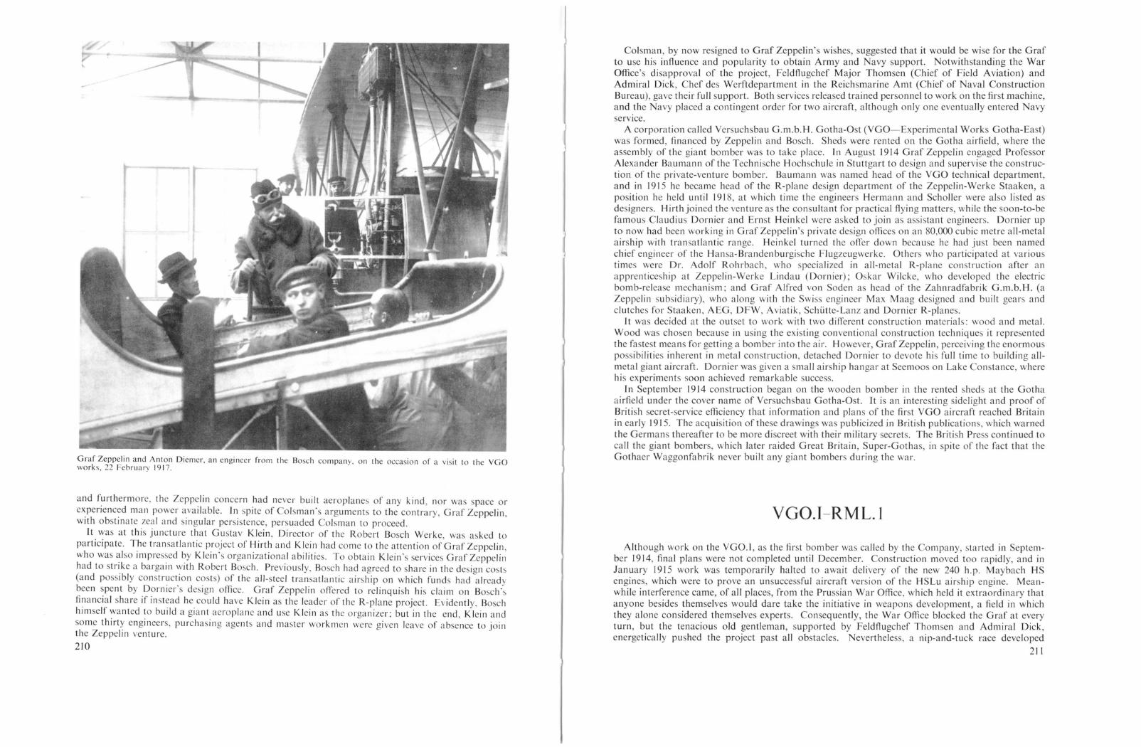
Graf Zeppelin and Anton Diemer, an engineer from the Bosch company. on the occasion of a visit to the VGOworks, 22 February 1917.
and furthermore, the Zeppelin concern had never built aeroplanes of any kind, nor was space orexperienced man power available. In spite of Colsman's arguments to the contrary, Graf Zeppelin,with obstinate zeal and singular persistence, persuaded Colsman to proceed.
It was at this juncture that Gu tav Klein, Director of the Robert Bosch Werke, was asked toparticipate. The transatlantic project of Hirth and Klein had come to the attention of Graf Zeppelin,who was also impressed by Klein's organizational abilitie . To obtain Klein's services Graf Zeppelinhad to strike a bargain with Robert Bosch. Previously, Bo ch had agreed to share in the design costs(and possibly construction costs) of the all-steel transatlantic airship on which funds had alreadybeen spent by Dornier's design office. Graf Zeppelin offered to relinquish his claim on Bosch'~
financial share if instead he could have Klein as the leader of the R-plane project. Evidently, Boschhimself wanted to build a giant aeroplane and use Klein as the organizer; but in the end, Klein andsome thirty engineers, purchasing agents and master workmen were given leave of absence to jointhe Zeppelin venture,
210
Colsman, by now resigned to Graf Zeppelin's wishes, suggested that it would be wise for the Grafto use his influence and popularity to obtain Army and Navy support. Notwithstanding the WarOffice's disapproval of the project, Feldflugchef Major Thomsen (Chief of Field Aviation) andAdmiral Dick, Chef des Werftdepartment in the Reichsmarine Amt (Chief of Naval ConstructionBureau), gave their full support. Both services released trained personnel to work on the first machine,and the Navy placed a contingent order for two aircraft, although only one eventually entered NavyserVIce.
A corporation called Versuchsbau G.m.b.H. Gotha-Ost (VGO-Experimental Works Gotha-East)was formed, financed by Zeppelin and Bosch. Shed were rented on the Gotha airfield, where theassembly of the giant bomber was to take place. In August 1914 Graf Zeppelin engaged ProfessorAlexander Baumann of the Techni che Hochschule in Stuttgart to design and supervise the construction of the private-venture bomber. Baumann was named head of the VGO technical department,and in 1915 he became head of the R-plane design department of the Zeppelin-Werke Staaken, aposition he held until 1918, at which time the engineers Hermann and Scholler were also listed asdesigners. Hirthjoined the venture as the consultant for practical flying matters, while the soon-to-befamous Claudius Dornier and Ernst Heinkel were asked to join as as istant engineers. Dornier upto now had been working in Graf Zeppelin's private design offices on an 80,000 cubic metre all-metalairship with transatlantic range. Heinkel turned the offer down because he had just been namedchief engineer of the Hansa-Brandenburgische Flugzeugwerke. Others who participated at varioustimes were Dr. Adolf Rohrbach, who specialized in all-metal R-plane construction after anapprenticeship at Zeppelin-Werke Lindau (Dornier); Oskar Wilcke, who developed the electricbomb-release mechanism; and Graf Alfred von Soden as head of the Zahnradfabrik G.m.b.H. (aZeppelin subsidiary), who along with the Swiss engineer Max Maag designed and built gears andclutches for Staaken, AEG, DFW, Aviatik, SchLitte-Lanz and Dornier R-planes.
It was decided at the outset to work with two different construction materials: wood and metal.Wood was chosen because in using the existing conventional construction techniques it representedthe fastest means for getting a bomber into the air. However, Graf Zeppelin, perceiving the enormouspossibilitie inherent in metal construction, detached Dornier to devote hi full time to building allmetal giant aircraft. Dornier was given a small air hip hangar at Seemoos on Lake Con tance, wherehis experiments soon achieved remarkable success.
In September 1914 construction began on the wooden bomber in the rented sheds at the Gothaairfield under the cover name of Versuchsbau Gotha-Ost. It is an interesting sidelight and proof ofBritish secret-service efficiency that information and plans of the first VGO aircraft reached Britainin early 1915. The acqui ition of these drawings was publicized in Briti h publications, which warnedthe Germans thereafter to be more discreet with their military secrets. The British Press continued tocall the giant bombers, which later raided Great Britain, Super-Gothas, in spite of the fact that theGothaer Waggonfabrik never built any giant bombers during the war.
VGO.l-RML.l
Although work on the VGO.I, as the first bomber was called by the Company, started in September 1914, final plans were not completed until December. Construction moved too rapidly, and inJanuary 1915 work was temporarily halted to await delivery of the new 240 h.p. Maybach HSengines, which were to prove an unsucce sful aircraft version of the HSLu airship engine. Meanwhile interference came, of all places, from the Prussian War Office, which held it extraordinary thatanyone besides themselves would dare take the initiative in weapons development, a field in whichthey alone considered themselves experts. Consequently, the War Office blocked the Graf at everyturn, but the tenacious old gentleman, supported by Feldflugchef Thomsen and Admiral Dick,energetically pushed the project past all obstacles. Nevertheless, a nip-and-tuck race developed
211

The VGO.I shown in its original form during the spring of 1915. This machine was the ancestor of the Staaken lineof R-planes.
between the completion date of the VGO.I and the patience of the military authorities which wasslowly running out. The situation was such that detached military personnel working on the bomberwere to be recalled and had but few days leave remaining when Hirth piloted the YGO.I on its maidenflight on II April 1915.
The flight crew consisted of two pilots seated in a large open cockpit, one commanderinavigatorand three mechanics, one for each engine. Their means of communication was very crude; itconsisted of bell signals and blackboards upon which orders were written. An eye-witness alsoremembers Hirth signalling vigorously by hand to the mechanics in the outboard nacelles.
Three 240 h.p. Maybach HS engines were installed; one was mounted in the fuselage nose anddrove a tractor propeller, the other two were mounted in nacelles, driving pusher propellers withinthe wing gap. Each nacelle was supported at mid-gap by a pair of inverted V-struts. In its originalform the fuel tanks were placed in the nacelles ahead of the engines. Initially uncowled, the frontof the nacelles were later covered by streamlined metal fairings. Cooling was provided by six Haegele& Zweigle radiators, one along each side of the nose engine and two similarly placed on each nacelle.
The four-bay wing structure with it swept-back leading edges and light negative tagger set thebasic pattern for all the Staaken design that followed. Structurally, the wing was very similar tothe Staaken R.Yl type, and is described in detail in that chapter. Plain unbalanced ailerons werefitted to the wings.
Typical of its day, the fuselage was a lab-sided structure with a rounded top-decking extendingforward from the large open dorsal cockpit behind the rear cabane struts to the nose. Aft of thisdecking the top and bottom longerons converged towards the tail to meet in a horizontal knife-edge.From the attachment point of the front cabane struts, the upper longerons were angled down towards
The VGO.I on its maiden flight at Gotha, II April 1915.
212
r J
VGO.T. The double interplane cables are here shown faired without first being drawn together as they were on alllater types. Standing in front of the aircraft are (from L. to R.) VGO engineers Hans Baumeister, Philipp Simon andForeman Hungs.
the thrust line of the nose engine. The rectangular fuselage was of mixed construction. with fourwood longerons and welded steel tubing frames; those in the forward part of the fuselage werereinforced with diagonal tubes. The fuselage was cable-braced and fabric-covered, with the exceptionof the plywood panelled top-decking and nose sides back to the pilot' position.
Provision wa made for bomb to be carried in a cage at the centre of gravity, but the 1000 kg.bomb for which this aircraft was originally developed was not dropped by R-planes until 1918.
The biplane tail surfaces were located at a point slightly below mid-gap by a pair of V-struts aboveand below the fuselage. In its general form the tail cellule was of narrow gap and incorporated foursmall fins and unbalanced rudders spaced along the span. Plain elevators were filted to both urperand lower tail urfaces. The control cables passed along the outside of the fuselage to large quadrantsat the cockpit.
Two simple V-type undercarriages, each with four wheels arranged in pairs, were positioned underthe nacelles. A imilar undercarriage of lighter construction was mounted beneath the nose. nlikethe later Staaken machines, the YGO.I rested on its nose wheels when fully loaded. This broughtthe wings with their large angle of incidence into take-ofT altitude.
The Maybach HS engine which pO'vvered the YGO.l was developed from a line of successful
213

Appearance or the VGO.I in t he aut umn of 1915, with modified nacelles and new tail unit.
machine. A large streamlined gravity tank, which was to become a permanent feature of later types,was built into the top of the centre-section cabane. A single radiator was fitted on the top of the nosefor the single tractor engine; the pusher engines retained their twin H & Z radiators. The originaltail unit had proved to be rather inadequate for directional control. It was replaced by one similarto that on the YGO.II, except that the fin area was increased and rudders balanced. The HS enginewas not replaced, for it was still the most powerful aircraft engine available; yet in spite of countlessimprovements and modifications, it was never equal to the task set before it.
The rebuilt VGO.I fir t flew on 16 February 1916. It was later accepted by the avy and thenas igned to avy Kommando L.R.I, a special group formed under the command of Lt.z.S.Ferdinand Rasch to evaluate the new weapon on the Eastern Front. The letters RM L.I paintedon the fuselage side stood for Reichs Marine Landflugzeug I (Reich avy Landplane I).Commanded by Rasch and flown by Navy pilots Lt. d. R. Carl Kuring and Flugmaat WillyMann, the RML.I left Gotha for Alt-Auz in June 1916. It took two months to complete thetrip that was normally a three-day flight. The trip to Doberitz was uneventful, but an unscheduledlanding was made en route at SchneidemLihl to perform minor engine repairs. Several days laterduring the take-off run, the nose landing gear broke away and the machine came to rest on itsnose. The small damage was promptly repaired and the RM L.I was on its way to Alt-Auz whenoverheating engines (made known to the pilots when the nacelle engine mechanics held up their
-------~
I
~~=======~~:=::=:::=::::=~-=::::=:-:=::=:::-- -6L
"i
!J',(} j5()--'----gzp --------'l(J(l ----------ZJ»J -------1
airship engines, but in the process of redesign and weight reduction it had fared badly. Beset bycontinual operational failures, particularly overheating at high revolution during take-off, the HSengine was responsible for sub tantial delays of the Staaken and SSW R-plane programmes; designerswere eventually forced to resort to less powerful but more reliable engine.
On 6 June 1915 the YGO.I made its first long cross-country flight from Gotha to the MaybachWorks in Friedrichshafen. It took six month, until the winter of 1915, to provide the YGO.l withsufficiently reliable HS engines so that the avy duration and acceptance flights could be flown in
Forward engine arrangement or the VGO.I and VGO.II.
..Friedrichshafen. On 15 December 1915 while on the return flight to Gotha with Hans Vollmbllerand Flugmaat Willy Mann at the controls and Hirth as aircraft commander. the VGO.T ran into asevere snowstorm over the Th uri ngen Forest. Due to a fai lure in the oil Ii nes. two of the three engi neshad cut-out. As it was impossible to maintain height on one engine, the crew had no choice but tomake a forced landing. With exemplary skill they put the machine down in a mall forest clearingat Geroldsgrl.in. with heavy damage to the aircraft but with no injuries to the crew.
This marked the end of nine months' sustained eA'ort to get the new Maybach HS engines runningproperly in an equally untried airframe. The team of engineers at Gotha were not discouraged bythis unfortunate crash. They collected the remains and rebuilt the machine incorporating manynew features. Profiting by the experience gained in flight testing the VGO.I, some of the improvements had already been built into the VGO.If, which had been completed by thi time.
As reconstructed, the VGO.I had cowled engines with gun positions for a gunner/mechanic in thefront of each nacelle. The interplane struts were faired, replacing the plain tubes of the original
214
Hellmuth Hirth's crash with the VGO.I in the Thuringen Forest. 15 December 1915.p 215

blackboards with the high temperatures chalked in large letters) forced an emergency landing ona small airfield near Konigsberg. New engines had to be installed. All was in readiness when,shortly before becoming airborne, the main undercarriage collapsed and the RM L.l slid to astop on its belly. Extensive and time-consuming repairs were required, but the newly-installedundercarriage was still not robust enough, and it collapsed again on the next take-off attempt.Finally, at the end of July 1916 the RML.l reached its destination at Alt-Auz. What today mayread like a comedy of errors was regarded at the time with much misgiving by the crews Ayingthese early unreliable and cantankerous R-planes. They greatly preferred to be aloft in a singleengined combat machine of proven worth.
According to the Kommando L.R.l. War Diary, the first bomb raid was made on 15 August 1916.after an abortive start on 13 August, when it was to have attacked in company with the Army R-plane
Mishap with the rebuilt VGO. [ (R M L. 1), during the take-off at Schneidemuhl for the journey to Alt-Auz, June 1916
(VGO.lI), then also stationed at Alt-Auz. The War Diary lists four bomb raids: the rail terminalat Schlok (15 August), the Russian air station at Lebara (L6 August), the air station at Runo Islandand troop encampment at Kemmern (17 August), and a cancelled raid on Kemmern (24 August)due to boiling left nacelle radiator shortly after take-off. On these raids the RM L. L carried a storeof bombs that varied according to the mission. Against air stations it carried 6 X 50 kg. (Karbonit).8 X 20 kg. (Karbonit), and 4 X 10 kg. incendiary (Goldschmidt) bombs. For attacks against troopinstallations 32 X 12 kg. (Karbonit), 2L X 20 kg. (Karbonit) and 9 X 10 kg. incendiary (Goldschmidt) bombs were carried. 1
Pasted into the last pages of the War Diary is a short telegram from the Commander of the BalticSea force to the Navy Staff dated 1 September 1916 saying that the "RML.l has in the meantimebeen damaged". Here is what had happened. It was night; pilots Kuring and Mann were at thecontrols and the RML. L had just taken the air fully loaded with fuel and bombs. The machine wasstraining for altitude when at 50 metres two of its engines, one after the other, "exploded". Havingno choice but to go down, the pilots guided the aircraft gently into the pine forest below; although
I See Eastern Front Operations for further details of these raids and Appendix 12 for information on bombs.
216
A further mishap to the RML.I en route to the Front. Undercarriage failure on the airfield at Konigsberg.
sixty-nine trees were sheared off, the dense foliage lessened the impact of the crash, which saved theRML.l from destruction by explosion or fire. Only the fuselage was worth salvaging, and it was sentback to Staaken to receive new wings and engines. The Kommando L.R.I. was disbanded, itsmembers received other assignments and everyone was relieved that the career of the unpredictableRML.I was finally ended-or so they thought.
It was decided to rebuild the underpowered RML. L by replacing the original three engines andincreasing their number to a total of five 245 h.p. Maybach Mb.IVa engines, one in the nose and two
Temporary shelter erected over the RM L.I while under repair at Konigsberg.
217

Crash of the RML.I in the forest near Alt-Auz on 28 August 1916.
in each nacelle geared to a single four-bladed propeller. 1 The Maybach Mb.IVa, a va t improvementover the HS engine, had become available in late 1916, and it was the first of the "over-compressed"engines developed by the Germans for high-altitude use (see Staaken R. VI chapter for details).Standard slab-type radiators were fitted, tho e on the' front struts being placed higher than the rearones. The entire tail plane structure was raised to the top longerons and modified to have a inglebay on each side. Like the Li-Ho R.T 8/15, the new fuselage and tail were entirely covered in Cellonin an attempt to make the machine partially invisible.
On 10 March 1917 the recon tructed VGO.l was readied for its maiden flight. The first pilot wasVollmoller, the second pilot was Kuring, who had been recalled from Marine Jagdstaffel 2. Raschwanted to go along too, but Gustav Klein, who had been ordered by Bo ch not to fly, jokingly toldhim to "stay behind and sweep up the pieces". Kuring stated that the VGO.l was still under Navycognizance, which explained his presence and that of the other Navy per onnel aboard. The take-offwent smoothly, but as the VGO.T was circling the Staaken airfield a terrific detonation occurred inthe left engine nacelle and the propeller stopped. The pilots immediately gave hard right rudder tocompensate for the unequal thru t, and the machine responded well, flying a straight line to landparallel to the large airship sheds. Three days previously, while familiarizing himself with thecontrols, Kuring discovered and immediately reported that the rudder pedals were not functioningproperly. Tn the hard-over position the pedal jammed and could not be returned to the neutralposition. This fault had not been repaired. As Vollmoller cut the remaining engines preparatory tolanding, the hard right rudder, robbed of its compensating force, slowly forced the VGO.I into aright turn. Kuring at once unfastened his afety belt and crept under the control panel to pull therudder pedals over from their jammed position. It wa too late. Vollmoller was helpless to preventthe VGO.T from rever ing course and smashing head-on into the door of the air hip shed. Vollmollerwas killed instantly, and Klein died after a few hours. Kuring was thrown out by the impact, andthough he uffered severe head injuries he was able to rejoin Marine Jasta 2 and thence enjoy a longand varied aeronautical career.
GrafZeppelin had died two days earlier on 8 March 1917. Thus, in a span of three days, GermanR-plane development had 10 t three of it most important contributors, but serious as the loss mayhave been, their heritage wa well founded. At that very moment the Staaken organization was
lOne source claims that two 160 h.p. Mercedes D.lIl engines geared to a single propeller were located in the nose.
218
V GO. I. FIRST FLIGHT FORM SPRING 1915.
V GO. I. AUTUMN 1915
V GO. I. REBUILT AS THE R.M.L.l
building and testing new R-planes, destined to be the only giant bombers to enter operational serviceon the Western Front. It was the sustained efforts and enthusiasm of people such as Graf Zeppelin,Gustav Klein and Hans Vollmoller which made this achievement possible.
Colour Scheme and Markings
The VGO.I as it first flew carried no markings; it was clear doped overall giving it a pale buff colour.Later, the black Patee cross on a white square background was painted on the wingtips, fuselage
219

Areas:Weights:
Fuel:Armamen!:Senice Use:
Dimensions:
Engines:
Areas:Weights:
Armament:Senice Use:
Four 245 h.p. Maybach Mb.lVa enginesTwo 160 h.p. Mercedes D.lIL engines
orFive 245 h.p. Maybach Mb.IVa enginesSpan, 42·2 m. (138 ft. 5;\- in.)Length, 24 m. (78 ft. 9 in.)Height, 6·6 m. (21 ft. 7;\- in.)Wings, 320 sq. m. (3443 sq. ft.)Empty, 7450 kg. (16,427 lb.)Loaded, 11,485 kg. (25,325 lb.)
Wing Loading: 37-4 kg. sq. m. (7'7 Ib./sq. ft.)Performance: Maximum speed, 130 km.h. (80,8 m.p.h.)
Climb, 3000 m. (9843 ft.) in 60 mins.Provision for dorsal, ventral and two nacelle machine-gun positionsNone
The VGO.II, first of a long line of Staaken giants accepted by the Army, was begun inDecember 19/4 and its first flight was made in early September 1915. The flight characteristicswere 'very satisfying' but radiator and engine problems caused appreciable delays. The VGO.IIwas accepted by Idflieg on 28 November 1915 and allocated the serial number R.9/15.
In construction and dimensions the airframe was virtually identical to the earlier VGO.I. However.in light of experience gained during test flights of the VGO.I, several modifications were made. Inparticular, the tail unit was redesigned; it retained the same biplane horizontal surfaces, but thegap was increased considerably. The number of vertical tail surfaces was reduced from four to two.but the rudders were given increased area, and the place of the inner rudders was taken by a pair ofinterplane struts. At a later date the fin area was increased by the addition of a large central fin.Another change was that the nacelles were fitted with a nose machine-gun position. The three240 h.p. Maybach HS engines were cooled by H & Z radiators placed alongside the engines as inthe prototype, with the exception that the fuselage radiators were of increased area. These werelater replaced by block radiators mounted above the nacelles and fuselage nose. Additional machinegun positions were located above and below the fuselage, one directly. behind the rear cabane. strutsand the other farther aft level with the lower-wing trailing edge. ThIS ventral pOSitIOn remaIned astandard feature on all later Staaken types.
In February 1916 the R.9 was delivered from Doberitz via Konigsberg to Rfa 500 at Alt-Auz.The 900 km. distance was flown in 71' hours in spite of snow flurries and low-hanging cloud cover,which forced the VGO.II to fly below 100 metres from Tilsit on. Offiziersstellvertreter (acting officer).
22L
VGO.II
VGO.H 9/15. Photo probably taken at Doberitz prior to its service in the East.
SPECIFICATIONS
sides and rudders. The tail markings occupied the complete area of the vertical tail surfaces. Theserial number RML.I was painted on the fuselage after the VGO.l was taken over by the Navy.In its final form, with five engines, the markings conformed to the current style, that is the Pateecrosses received thin white outlines.
Wreckage of the final version of the VGO.I at Staaken. Both Hans Vollmoller and Gustav Klein were killed in thiscrash on 10 March 1917.
SPECIFICATIONS
TJ'pe:Manufacturer:Engines:Dimensions:
VGO.I-RM L.I (three-engined version)Versuchsbau G.m.b.H., Gotha-OstThree 240 h.p. Maybach HS enginesSpan, 42·2 m. (138 ft. 5-} in.)Length, 24 m. (78 ft. 9 in.)Height, 6·6 m. (21 n. 71 in.)Wings, 332 sq. m. (3572 sq. ft.)Empty, 6520 kg. (14,377 lb.)Loaded, 9520 kg. (20,992 lb.)
Wing Loading: 29·7 kg.lsq. m. (6,1 Ib./sq. ft.)Performance: Maximum speed, 110 km.h. (68-4 m.p.h.)
Climb, 2000 m. (6562 ft.) in 39 mins.Ceiling, 3000 m. (9843 ft.) in 79 mins.1500 litres (330 Imp. Gals.)Provision for dorsal, ventral and nacelle machine-gun positionsEastern Front with Kommando L.R.1. at Alt-Auz, August 1916
TJ'pe: VGO.I (five-engined version)Manufacturer: Versuchsbau G.m.b.H., Gotha-Ost
220

If
105 MM. CANNON SHOwN FITTED TO THE VG.o. II
near Mitau. Just short of coming to a stop, the VGO.H ran into a shallow ditch, which tore awaythe undercarriage, but with the exception of one broken strut, the aircraft was undamaged. Repairswere quickly made, and within a few days Vollmoller and Li.'lhr flew the VGO.lI back to Alt-Auz.
LLihr, who was also technical officer of Rfa 500, recalled an abortive attempt to place a machinegunner in the tail of the VGO.II. On return from the sole test flight the hapless gunner was pulledout of the tail more dead than alive. Tail oscillations due to the flexibility of the fuselage structure(a common occurrence in the Staaken R-planes) had given the gunner a severe bout of air-sickness.
Another recollection of interest is that each time a downdraft was encountered the danglingKarbonit bombs, which were suspended vertically in the bomb bay, clanked together, making oundslike a "dancing skeleton", not to mention the adverse influence of the swinging mass of bombs onthe flight characteristics.
I,IJ_Selmer piloted the VGO.II on anum bel' of operational test flights. While he claimed that the VGO.II
dropped bombs on Russian targets as early as March 1916, no records have been found to back uphis statement. It was not until five months later that the VGO.II was to receive credit for the firstacknowledged successful R-plane bombing attack.
On 13 August 1916 the VGO.1f took off from Alt-Auz, under the command of OberleutnantHaller von Hallerstein, and successfully bombed the Russian rail junction at Schlok. The bomherwas in the air for 3 hI'S. 30 mins., carrying a useful load of 2296 kg. and reaching an altitude of2500 metres. The VGO.I [ participated in a number of effective missions, such as the attack on theRussian railway station at Rodenpois in late autumn 1916. Having taken-off in the face of rapidlydeteriorating weather, unexpected strong head winds were encountered on the return flight, andwith 40 km. to go, the fuel ran out. The flight crew (Lt. LLihr, Lt. Frhr. von Buttlar and commanderLt. Max Schaefer) made a safe emergency landing on a small Fokker fighter field at Paulsgnade
The VGO.Tl 9/15. Photo dated 5 November 1915.
Official drawing above shows installation of 105111111. cannon, the gun actually l110unted in theVGO.1l was of 130111111. calibre.
The emergency landing of the R.9 at Paulsgnade near Mitau.
222
Among the more fascinating episodes in the development of R-planes was the installation of adownward-firing 13 em. (5,13 in.) calibre cannon (called Aussstossrohr or launching tube) in theVGO.IL Leutnant Dr. Ernst Neuber of Fea 3 at Gotha reasoned that the higher the velocity of adownward-launched projectile, the shorter its flight duration, hence the better its accuracy and thegreater its impact velocity. Neuber's report includes calculations on the feasibility of penetrating thedeck armour of British battleships. On 10 February 1916 Neuber was authorized by the PrLlfanstaltund Werft to proceed, and on 25 Maya 12 kg. projectile was test fired from a 20 metre high towerinto a 10 metre deep pit. A recoil force of 500-800 kg. was measured. Although VGO engineerswere sure a 1500 kg. recoil force could be safely absorbed, the VGO.lI structure was neverthelessreinforced. The cannon was mounted near the centre of gravity. Ground firing trial were performedon 6 and 10 October 1916 with varying powder charges. The recoil was only slightly noticeable, andin no way considered to be dangerous. After some small improvements and installation of a simpleaiming device airborne firing tests were conducted on 19 October 1916. Again the much-fearedrecoil problem was found to be non-existent, the aircraft easily absorbing the recoil forces. Firingfrom a height of 800 metres, the shots missed the target by 40-45 metres. but this was blamed on
223

Dihedral upper, nonelower, 3 degrees
Length, 23·78 m. (78 ft.)Height, 7 111. (22 ft. II-} in.)Tailspan, 9 m. (29 ft. 6 in.)Wheel diameter, 1·02 m. (3 ft. 4 in.)Propeller diameter, 3·88 m. (12 ft. 9 in.)Wings, 332 sq. m. (3572 sq. ft.)Wings. 2,070 kg.Tail unit, 365 kg.Fuselage, 1,270 kg.Accessorie , 140 kg.Undercarriage, 793 kg.Engines, 1,999 kg.
the inadequacy of the aiming device. The gun was returned to the factory for modification, and itis not known if further tests were conducted with the VGO.l[; although a high-velocity 10·5 cm.calibre cannon was ordered on 7 November 1917. euber propo ed a cannon-carrying. 2000 h.p.R-plane (see page 151) and obtained a patent, No. 305,039, for the gun-mounting system.
As the newer R-planes became available for service, the underpowered VGO.I [wa retired fromoperational service and relegated to training air crews at Ooberitz. As a trainer, the VGO.([ gavegood service, and many of the crews that Aew more powerful and improved giants later in the warmust have had their first experience in this machine. ]n official records it was carried as a trainingmachine attached to the Rea in Doberitz as of I January 1917. The following June it was underrepair and it was fitted with a strengthened undercarriage. The end of the VGO.II came when itcrashed and broke its back at Staaken, the exact date is unknown but it was probably in the summerof 1917. Photographs show that the machine did not catch fire, there are no reports of any officersbeing killed in the incident and the crew are believed to have escaped.
Dimellsiolls:
Areas:Weights:
Empty,Fuel,Disposable load,
6,637 kg. (14,635 lb.)1,126 kg. (2,483 lb.)2,440 kg. (5,380 lb.)
A rl11al11ellt:Sen'ice Use:Cost:
The final landing of the R.9 at Staaken, summer 1917. Note the raised tail
In the spring of 1915 Austria-Hungary became interested in R-planes, and the greak Skoda workspurchased a set of bomber plans, osten ibly of the VGO.l or VGO.II, from which an improved typewa to be built. However, in spite of Austria-Hungary's thriving aircraft industry. no R-planeswere ever constructed in that country.
Colour Scheme and Markings
The VGO.([ was clear doped overall. The Patee cross on a white background was painted on theouter surfaces of the fin and rudders, fuselage sides, the top and underside of the upper wingtipsand on the underside of the lower wingtips. At a later date the style of the Patee cro es was changedand the serial number R.9f15 painted in black on the sides of the fuselage.
Loaded, 10,203 kg. (22,498 lb.)Willg Loading: 30·7 kg. sq. m. (6'3 Ib.:sq. n.)Peljormallce: Similar to VGO.LFuel: Tank I, 1120 litres (247 Imp. Gals.)
Tank 2, 668 litre (147 Imp. Gals.)Gravity tank, 24 litres (5,3 Imp. Gal.)Oil engines, 36 litres (7,9 Imp. Gals.)Oil tank, 102 litres (22-4 Imp. Gals.) . . .Provision for dorsal, ventral and two nacelle machine-gun positions .Eastern Front with Rfa 500 at Alt-Auz 19J6. Training machine at Dobentz 1916-17The German Government paid 360,000 marks for the VGO.II. Construction co t
40 1,000 marks, and engines cost 75,000 marks.
VGO.III
During October 1915 construction of the third Staaken giant, the VGO.II r, wa ?egun at Gotha.Early in the design stage it wa decided to find alternative engines for t.he expenmen.ta1 240 h.p.Maybach HS engines, which had proven to be unreliable for extended flights. In their place, thethoroughly-tested 160 h.p. Mercedes 0.111 engine was chosen, and to compensate for their loweroutput, six engines were used, increasing the total horse-power of the VGO.lll to 960 h.p. as comparedto the 720 h.p. available to the first two VGO types. . .,
The method of installation was entirely new. Two engines were mounted side by side In the
~~--=:.:.-_-_......._-------.;~_-..:.._~ ............=--
Type:.\1allll(actllrer:EngilJes:Dimellsiolls:
224
SPECI FlCAnONS
VGO.l[Versuchsbau G.m.b.H., Gotha-OstThree 240 h.p. Maybach HS (or Mb.IV) enginesSpan, 42·2 m. (138 ft. 5-t in.)Chord inner, 4·6 In. (15 ft. 1 in.)
outer, 3·6 111. (II ft. 10 in.)Gap inner, 4·6 111. (15 n. I in.)
outer, 3·6 In. (11ft. 10 in.)Incidence inner, 51- degrees
outer, 2 degrees
~.- -' .~ .,--. '_ • ~ l' ",
-"'I' .... _~. ' ~".,. .,....... ",""",,;;
VGO.lll 10/15.225
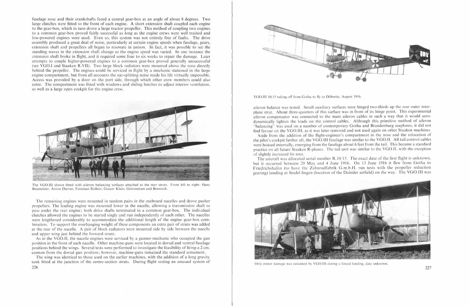
fuselage nose and their crankshafts faced a central gear-box at an angle of about 8 degrees. Twolarge clutches were fitted to the front of each engine. A short extension shaft coupled each engineto the gear-box, which in turn drove a large tractor propeller. This method of coupling two enginesto a common gear-box proved fairly successful as long as the engine crews were well trained andlow-powered engines were used. Even so, this system was not entirely free of faults. The driveassembly produced a great deal of noise, particularly at certain engine speeds when fuselage, gears,extension shaft and propellers all began to resonate in unison. In fact, it was pos ible to see thestanding waves in the extension shaft change as the engine speed was varied. ]n one instance theextension shaft broke in flight, and it required some four to six weeks to repair the damage. Laterattempts to couple higher-powered engines to a common gear-box proved generally unsuccessful(see YGO.I and Staaken R.YII). Two large block radiators were mounted above the nose directlybehind the propeller. The engines could be serviced in flight by a mechanic stationed in the largeengine compartment, but from all accounts the ear-splitting noise made his life virtually impossible.Access was provided by a door on the port side, through which other crew members could alsoenter. The compartment was fitted with windows and sliding hatches to adjust interior ventilation,as well as a large open cockpit for the engine crew.
The VGO.lI 1 shown fitted with aileron balancing surfaces attached to the rear struts. From left to right: HansBaumeister, Anton Diemer, Foreman Ridlein, Gustav Klein, Grimmeisen and Boenisch.
The remaining engines were mounted in tandem pairs in the outboard nacelles and drove pusherpropellers. The leading engine was mounted lower in the nacelle, allowing a transmission shaft topass under the rear engine; both drive shafts terminated in a common gear-box. The individualclutches allowed the engines to be started singly and run independently of each other. The nacelleswere lengthened considerably to accommodate the additional length of the engine-gear-box combination. To support the overhanging weight of these components an extra pair of struts was addedat the rear of the nacelle. A pair of block radiators were mounted side by side between the nacelleand upper wing just behind the forward struts.
As in the VGO.II, the nacelle engines were serviced by a gunner-mechanic who occupied the gunposition in the front of each nacelle. Other machine-guns were located in dorsal and ventral fuselagepositions behind the wings. Several tests were performed to investigate the feasibility of firing a 2 em.cannon from the dorsal gun position; however, machine-guns remained the standard armament.
The wing was identical to those used on the earlier machines, with the addition of a long gravitytank fitted at the junction of the centre-section struts. During flight testing an unusual system of
226
VGO.III 10/15 taking.off from Gotha to fly to D6beritz, August 1916
aileron balance was tested. Small auxiliary surfaces were hinged two-thirds up the rear outer interplane strut. About three-quarters of this surface was in front of its hinge point. This experimentalaileron compensator was connected to the main aileron cables in such a way that it would aerodynamically lighten the loads on the control cables. Although this primitive method of aileron"balancing" was used on a number of contemporary Gotha and Brandenburg seaplanes, it did notfind favour on the VGO.lI r, as it was later removed and not used again on other Staaken machines.
Aside from the addition of the flight-engineer's compartment in the nose and the relocation ofthe pilot's cockpit farther aft, the VGO.llI fuselage was similar to the VGO.ll. All tail control cableswere housed internally, emerging from the fuselage about 6 feet from the tail. This became a standardpractice on all future Staaken R-planes. The tail unit was similar to the VGO.lI, with the exceptionof slightly increased fin area.
The aircraft was allocated serial number R.IOjI5. The exact date of the first flight is unknown,but it occurred between 29 May and 4 June 1916. On 13 June 1916 it flew from Gotha toFriedrichshafen (to have the Zahnradfabrik G.m.b.H. run tests with the propeller reductiongearing) landing at Sindel fingen (location of the Daimler airfield) on the way. The VGO.lll was
Only minor damage was sustained by VGO.III during a forced landing, date unknown.227

~.~/ /'
(n~ ~7. I, r
- l-- E/1 ,// l-f-
- --....
- -- -
u/
/
X(,
- ,,,-
----------
,, '
oo
- - -__ I'
.~ ,
1=
I--
f--
-
1=
t--=I=§-
(/
n
VGO.llI IOll5
1=1----- -/
, .l
-
-
I--
---
=1=
I---
F~1-----
I- - ----
I--- -
I----
accepted by Idflieg (Rea) on 28 August 1916 and delivered to Rfa SOO on 8 September. Offstv.Selmer, who also piloted the VGO.llI, stated that the bomb installation was improved overearlier types, in that the bombs were hung beside each other rather than over one another andwere released electrically. The crew consisted of seven men, including one wireless operator whoworked the only type of wireless set fitted to R-planes at the time: a Siemens-Schuckert transmitterinitially built for Austrian bombing planes and a Telefunken receiver. Power was supplied byan AEG generator driven by a small 2-cylinder Bosch petrol engine. Attempts to drive thegenerator by coupling it directly to the engines or by a small slipstream-mounted propeller wereunsuccessful.
The VGOOlIl completed about seven bombing missions, during which it targets were railwayinstallations, troop encampments and depots in the vicinity of Riga. On a 3 hr. 10 min. bombing
The VGO.lll is here shown resting all its tailskid; the more normal attitude was for it to rest on its nose wheels withthe tail high.
228
\=
VGom SERIALNo.R.10/15

mission on 22 September 1916, it carried a useful load of 3310 kg. and reached an altitude of 3000metres.
On 24 January 1917 the first fatal R-plane accident occurred when the VGO.lll, returning froma training mis ion, came in to land at Alt-Auz. With Selmer at the controls, the VGO.l U wasforced to touch-down prematurely due to a sudden downdraft. The ground wa soft and coveredwith snow, and after some 10 metres the front wheels struck a hidden obstruction and snapped off.The sudden braking action cau ed the main undercarriage to collapse, the fuselage to break in twoand the lower wings to tear off. The ruptured fuel lines sprayed petrol over the nose exhaust stacks,and the VGO.1I1 was completely destroyed by fire, with loss of five crew members. A survivorstated that the forward fuel tank had burst on impact and had filled the fuselage with petro\. Atan inquiry into the causes of the accident it was concluded that the nose undercarriage strutswere too robust. Had they broken away sooner on striking the obstruction, the crash might nothave been so serious. On later Staaken types the nose undercarriage or "Srossfahrgesrell" wasconsiderably shortened and possibly reduced in strength.
Colour Scheme and MarkingsThe VGO.lH was clear doped overall, giving it a cream-buff colour. The cross Patee on white
squares was carried on the fuselage sides and on all four wingtips. The outer fin and rudder surfaceswere painted all white, and the cross Patee was the largest pos ible for the area available. No othermarkings were visible.
T)pe:Manufacturer:Engines:Dimensions:
Areas:Weighrs:
Pel!ormance:
Fuel:A rmalJlelll:Serrice Use:
SPECIFICATIO S
VGO.llJVersuchsbau G.m.b.H., Gotha-OstSix 160 h.p. Mercedes 0.111 enginesSpan, 42·2 m. (138 ft. 5t in.)Length, 24·5 m. (80 ft. 4t in.)Height, 6·8 m. (22 ft. 3t in.)Wings, 332 sq. m. (3572 sq. ft.)Empty, 8600 kg. (18,963 lb.)Loaded, 11,600 kg. (25,578 lb.)Bomb load, 400-800 kg. (882-1764 lb.)Maximum speed, 120 km.h. (75 m.p.h.)Climb, 1000 m. (3281 ft.) in 16 mins.
2000 m. (6562 ft.) in 29 min.3000 m. (9843 ft.) in 56 mins.
eiling, 3000 m. (9843 ft.)Duration, 6 hours3500 litres (770 Imp. Gals.)Provision for two dorsal, one ventral and two nacelle machine-gun positionsEastern Front with Rfa 500 at Alt-Auz, September 1916-January 1917
Staaken R.IV
(Staaken). With the reduction of airship construction in 1917 and its stoppage in January 1918,the Flugzeugwerft G.m.b.H. was easily able to absorb the airship workers and hangar space.
A contemporary report states that the fourth VGO R-plane was in its first stages of constructionat Gotha in February 1916. The machine completed its maiden flight on 16 August 1916, and by
The form in which the Slaaken R.I Y 12/15 first flew.
the time it had fini hed its flight te ts the transfer of VGO to Staaken had taken place. Con equently.on being delivered to the Army this machine was the fir t of the Zeppelin-built giants to be officiallydesignated a Staaken type, and under the Idflieg numbering ystem was known as the StaakenR.IV 12/15.
The general layout of the Staaken R.IV followed closely that of its predecessor, the VGO.lIl. Therewas no change in the installation of the two 160 h.p. Mercedes D.lII engines in the nose. The onlyvisible differences were the close spacing of the two radiators and the exhaust stacks fitted intochannels in the upper fuselage panelling. This in contrast to the VGO.lIl, where the stacks werehoused internally and emerged at a harp angle from the side panels.
The Staaken R.IY prior to the filting of upper wing armament.
With the growth of Allied air power. the possibility of an air strike against the Zeppelin airshipworks at Manzell became increasingly threatening. To forestall a possible crippling blow to theGerman airship programmc, Major Thomsen urged the Zeppelin concern to establish a subsidiaryairship works in a safer location, which it did in early 1916 at Staaken near Berlin. On I August1916 the VGO works wa officially transferred from Gotha to Staaken and renamed FlugzeugwerftG.m.b.H. The move was a natural outcome of the growth of the industry. Staaken would offerbetter facilities for the expansion of Zeppelin R-plane production and release space for GothaWaggonfabrik. On 15 June 1916, the first group ofVGO personnel began the transfer to Berlin
230
The desirability for morc power and thc availability of the new 220 h.p. Benz BZ.IV engines ledto their installation as tandcm pusher units in the nacelles. The additional 240 h.p. over the VGO.11lgave the Staaken R.I Va total of 1200 h.p. and made it the first of the more powerful second generationStaaken R-planes. The engine coupling in the R.IV proved very uccessful, primarily for the reasonthat exceedingly well-traincd cngine crews had been assigned to this machine, making a thoroughtest programme possible. In fact. the R.IV was the only R-plane with coupled engines to see serviceon both the Eastern and Western fronts up to the very end of the war. A remarkable showing.considering the difficulties experienced by other Staaken R-planes fitted with coupled engines.
Q 231

Mechanics working in the port engine nacelle of theStaaken R.IV 12 15.
The same wing structure was employed, differing only in the reduction of lower wing dihedralfrom 3 to It degrees.
The fuselage was shortened slightly ahead of the wings; the open engineer's cockpit was replacedby a square hatch with sliding covers and the ventral machine-gun position wa lowered to improvethe field of fire. The resultant fairing produced a noticeable bulge under the fuselage.
Although the tail remained structurally the same, it was raised to a position above the fuselage toprevent damage to the tail surfaces when landing on the tail skid. The lower tail pars ran under thetop fuselage longeron, a feature retained on succeeding type.
With the exception of landing lights attached to the auxiliary struts, the design of the undercarriageremained unchanged.
A great deal of thought was given to the defensive armament of the R.IV. Soon after initial flighttests, machine-gun po itions were built into the upper wings directly above the nacelles and behindthe rear wing spar. Counting the two dorsal, one ventral and two forward nacelle gun positions, aformidable armament of seven machine-guns could be carried; a considerable number for oneaircraft at that time. The wing position was reached by climbing a ladder leading from the nacelleto a platform hinged to the rear nacelle struts. The platform could be folded to allow the gunner toclimb up and down, and sliding panel above and below the wing enclosed the position when not inu e. The ladder was completely exposed and only a few feet from the propeller, 0 that the journey
233
Member of the crcw of the Staaken R.IV ascending tothc upper wing gun platform.
The nacelle engines were arranged in the same way as in the VGO.III, but it was necessary onceagain to lengthen the nacelles to accommodate the new gear-box, Mercedes-built clutch and largerengines. Zahnradfabrik G.m.b.H., a Zeppelin subsidiary, built the gear-box, which reduced the1400 r.p.m. of the engine to 860 r.p.m. for the propellers. The Garuda four-bladed propellers rotatedin opposite directions and were placed well clear of the trailing edges. Initially the nacelle radiatorswere mounted in the manner of the VGO.III, but as these did not provide sufficient cooling, theywere replaced by larger radiators mounted on front and rear nacelle struts; the front radiator washigher than the rear to avoid blanketing the rear radiator.
Forward engineer compartment of the Staaken R.IV.
232
Dorsal gunner's position on the Staaken R.1V.

Staaken R.IV 12/15 in night camouflage on the Scheldewindeke airfield.
to the gun position must have been both exciting and hazardous. IdAieg considered the wing positionuseful, for they continued to be installed in several of the later Staaken types.
After Aight tests and modifications were successfully completed the R.IV was accepted by the
The Staaken R.IV and its crew at Kassel after the war. The targets attacked, the total weight of bomb dropped andplaces flown to have been chalked on the fuselage side.
234
t-t-
c~·~~~ .-«:~;..:,c; _.' ·o:':'~_ ;::{;~
.I~\>T---- . . ;. ~ ----
.(
I- -- ----,I- /
~'~.. \ : , ~, , .. ,
I ' 0
j:0, , . -- ~ ~I
P
~/
r-- ~
(rJ;= ~
---=~"'-:::::::::1~
/
II
1\--
>! ..
,/ -
.;'~ff --·lBtI? hb<
t-~ -~-=
/.~~--
f-~ r ))-,;; Fi~ r;J= 1~1-
~±l! :::;:0;I-
,--
-
~
./
\\ f- -=~ ./
Id
fi n
'!V1 T! f-
~~~/ " l'O<.I.
~:.. 7-:-:-~!. f; ..\!\ ~ / ~8I ::: • IIf ~ .... .
: ~
~'>ffi - 1 l -
0 V . > ,STAAKEN R.N SERIAL No. R.12/15 1,1,1,1,1,1,1
.sc.-... T..r.
,.~

Army Air Services on 5 May 1917 to begin an operational service life longer than any other R-plane.On 12 June 1917, the R.lY wa flown to Alt-Auz from Gotha via Doberitz and Konigsberg to joinRfa 500. The flight went smoothly in every re pect. On the Eastern Front the R.lY participated inraids on Wolmar (28/29 June 1917), Oesel (8/9 July 1917) and possibly other Russian targets. Acontemporary report describes the transfer of the R.ty to the Western Front.
On the flight from Alt-Auz to Metz the stages Alt-Auz-Konigsberg and KonigsbergDoberitz were completed without mishap. The fact that both stages were flown at night,without speciflc orders to do so, is proof of the crew's confldence in the aircraft. Thelanding in Konigsberg on 18 July 1917, performed in ground fog, went smoothly.
A signed to Rfa 501 stationed in the Ghent district, the R.lY listed London. Chelmsford, ThamesEstuary. Calais, Morville, Boulogne, Etaple , Ie Havre, Gravelines, Deauville and Doullens as itstargets in its long and varied career on the Western Front, during which a total of 25.000 kg. bombswere dropped. It also survived a collision with the balloon apron guarding London (see Operationalchapter for details). After the war the R.lY, presumably en route to Liegnitz to be broken up. was.in April 1919, shown to awed crowds at Kas el and other German cities.
C%ur Scheme and Markings
]n its first form the R.IY was clear doped overall and carried national markings of the same tyleand pattern as the YGO.III. Later, with the installation of the wing gun positions. it was eitherre-covered in printed fabric with the standard irregular polygon design, or the design was paintedover the old fabric. The Patee eros es were outlined in white on the camouflage pattern. but bymid-1918 these had been changed for the Latin eros with narrow white outlines. These cro sesoccupied the full chord of the wings, the depth of the fuselage side and the entire area of the finsand rudders.
Wing Loading: 39·2 kg. sq. m. (8,0 lb. sq. f1.)Performance: Maximum speed, 125 km.h. (77'5 m.p.h.)
Climb, 1000 m. (3281 f1.) in 10 mins.2000 m. (6562 n.) in 35 mins.3000 m. (9843 n.) in 89 mins.
Ceiling, 3700 m. (12,139 n.)Duration, 6-7 hI'S.
Fuel: 2080 litres (458 Imp. Gals.)Oil engines, 53 litres (11,7 Imp. Gals.)Oil tank, 130 litres (28'6 Imp. Gals.
Armamenl: Provision for six to seven machine-gun positions.Senice Use: Eastern Front with Rfa 500 at Alt-Auz, June 1917 to July 1917. We tern Front with Rfa
501 in Ghent area July 1917 to ovember 1918.
Staaken R.V
The Staaken R.Y was another step in a series of experiments to develop the correct formula forthe decentralized-engined Staaken giants. Wherea the previous Staaken types represented a combination of tractor and pusher propulsion, the R. Y had all its engines driving tractor airscrews. Thisconflguration was cho en to provide a powerful and free field of fire to the rear. The R.Y. with itsfive Maybach engines, was the most powerful German R-plane until the advent of the Benz-poweredAviatik licence-built Staaken R.xyl.
SPECIFICATIONS
Staaken R.lVFlugzeugwerft G.m.b.H., Staaken, BerlinTwo 160 h.p. Mercedes 0.111 enginesFour 220 h.p. Benz Hz.IV enginesSpan, 42·2 m. (138 n. 5t in.)Chord inner, 4·6 m. (15 f1. I in.)Chord outer, 3·6 m. (II f1. 10 in.)Incidence inner, 31 degreesIncidence outer, 2 degreesDihedral upper, oneDihedral lower, 1+ degreesLength, 23·2 m. (76 n. I in.)Height, 6·8 m. (22 f1. 3i in.)Tail span, 9 m. (29 f1. 6 in.)Wheel diameter, 1·02 m. (3 n. 4 in.)Tractor propeller diameter, 4·2 m. (13 f1. 9 in.)Pusher propeller diameter, 4·3 m. (14 n. I in.)Wings, 332 sq. m. (3572 q. n.)Wings, 2,350 kg.Fuselage, 1,450 kg.Tail unit, 400 kg.Undercarriage, 900 kg.Accessories, 123 kg.Engines and transmission, 3,549 kg.
Type:M anUlaClllrer:Engines:
Dimensions:
Areas:Weigh IS:
236
Empty,Fuel,Disposable load,
Loaded,
8,772 kg. (19,342 lb.)2,140 kg. (4,719 lb.)2,123 kg. (4,681 lb.)
13,035 kg. (28,742 lb.)
1Staaken R. V J 3tI 5.
The engine layout could best be described as the Staaken R.IY sy tem in reverse. Two engines ineach nacelle were coupled to a common gear-box which drove a four-bladed Garuda tractor airscrew.The rear engine was stepped down to allow its transmission shaft to pass under the forward engine.Viewed from above, each engine wa offset slightly from the nacelle centre line. In contrast to theR.IY, the similar tran mi ion system of the R.Y proved troublesome. The technical problemsrequired a long time to solve, and many minor change were made before the necessary reliabilitywas attained. The more powerful 245 h.p. high-compression Maybach Mb.lYa engines gave rise togreater transmission forces, as compared to the lower-powered engines of the R.IY, and this is wherethe trouble lay. As a result, the R. Y, which was begun in June 1916, was not accepted until 29September 1917, some three months after the Staaken R.YIl 14/15 and Staaken R.Y] 25/16.
237

O'F------1
STAAKEN R.:Il SERIAL No. R.13;!s
Staaken R. Y J3' 15, fitted with two-bladed propeller at the nose.
The basic airframe followed closely the configuration of the previous Staaken machines, with fewexception. The streamlined engine nacelles were a departure, for they were built of a woodenframework covered with plywood. This monocoque construction helped reinforce the engine mountsto the extent that vibrations and oscillation were greatly reduced. The engines were easily accessible,because internal bracing and cable work was eliminated. The stre3mline form was aerodynamicallydesirable but time-consuming and expensive to fabricate, precluding its use on succeeding Staakenaircraft. The nacelle underside remained open to allow fuel and vapours to escape. The tail of eachnacelle extended well beyond the trailing edges of the wing, and each wa equipped with a machine-gunring that was to be manned by the flight mechanics.
The single, geared Maybach engine in the nose wa cowled by aluminium panels in a mannersimilar to the R.IY and R.Vll machines. The Maybach engines required five large radiator; one
Slaaken R.Y 13 15. The engincs are being tcstcd in preparation for a night mission from Scheldcwindeke in 1918.
238

Areas:Weights:
Type:M anujacturer:Engines:Dimensions:
was installed above the fuselage nose and the remaining four were attached to the front and rearupper nacelle struts, staggered to avoid blanking each other.
Wing construction and dimensions were identical to the previous Staaken machines. Night-landinglights were fitted in the lower-wing leading edge in front of the inner struts.
The fuselage, though structurally similar to earlier Staaken machines, was considerably shortenedfrom the centre-section struts aft. This segment and tail presaged the construction of the R.Ylmachines. Crew accommodations followed the pattern set by the YGO.lI r. The flight mechanic'scompartment was located directly behind the nose engine, followed by a large open pilots' cockpitand a similar open commander's position. Dorsal and ventral machine-gun positions, located behindthe centre section, supplemented the strong tail defence. To provide a forward-firing gun positionthe gravity tank was encased in a streamlined pod which extended ahead of the upper-wing leadingedge. A machine-gun post, known as the "Swallow's Nest", was located in this extension and couldbe reached by a ladder set between the cen tre-section struts.
Gun positions of the Staaken R.Y.
Strange as it may seem, the R.Y was fully equipped with a pneumatic-tube message system withsix receiving and sending stations. The problem of communicating in an R-plane was difficult tosolve. Various attempts were made in the early giants to use such forms of acoustical communicationas telephones, sirens and speaking-tubes. But these failed due to the loss of hearing experienced bycrews during long flights. Optical devices ranged from the simple chalkboard to complicated opticalsystems, such as writing on frosted glass and projecting the message through prisms and lenses on toan opaque surface. Another technique which met with little success was to run messages along awire track from tation to station. ]n the end, the pneumatic-tube device, although an acceptabletechnique, lost out to the simpler electric telegraph, which used ten or twenty pre-set signals tofurnish information and commands. The pneumatic telegraph in the R.Y was operated by turninga crank: a right-hand turn created air pressure and a left-hand turn created suction. A signal lightautomatically lit in the receiving station when a me sage was placed in the tube.
Jt is known that Lt. Otto Reichardt was transferred to Gotha to take command of the R. Y. Itmay be assumed that the R.Y was the last Staaken R-plane to be built in Gotha and that Dipl.-lng.Lt. Reichardt was responsible for bringing the R.Y up to operational status. The crew of the R.V.larger than in most R-planes, numbered eleven men, consi ting of one commander, two pilots, threemechanics, one wireless operator, one fuel attendant and three gunners.
The R.Y 13/15 was accepted at Staaken on 29 September and joined Rfa 501 at Ghent on 23December 1917. Its first bombing mission was on 25 January 1918 when it attacked harbour installations at Calais. During its eight months service career, the R. Y flew only sixteen combat
240
miSSions. This low total is a reflection of the recurring mechanical failures which plagued the powertransmission system. The most notable mission recorded in the R. Y war diary took place on. 7/8March 1918 when the R.Y carried a useful load of 4771 kg. at an altitude of 3300 metres on a flightlasting seven hours1 . Although the right front clutch failed over Lon~on, th~ R.V returned homesafely. Lt. Reichardt was transferred home during late 1918 to serve With Idflleg, where he utlltzedhis experience a front-line pilot and R-plane commander to lIlstltute a series of. nnprovementswhich, it is said, greatly increased the performance of the Staaken R-planes. Later 111 1918 he waskilled while assisting in the development of the AEG R.t
Waldemar Roeder recalls his flying as second pilot on the R.Y while serving with Rfa 501. Thecommander was Lt. Ernst Pickerott and first pilot, Yizefeldwebel Heinz Schmitz. The .f1Ylngqualities of the R.Y, as with all Staaken aircraft, were rather comfortable and stable, If onedisregards the rather high control forces, particularly the unbalanced aIlerons. The steering wheelhad to be turned several times until the ailerons "caught", and then It took conSIderable tllneuntil the aircraft reacted.
With the fusion of Rfa 500 and Rfa 501 the R.Y flew to Morville in October 1918. On 18October 1918 the R.V was ordered to Di.isseldorf-Lohausen. During the flight, fog was encounteredin the Rhein area. Much against the better judgment of Schmitz and Roeder, Pick~r~tt orderedan emergency landing. ]n the attempt, the aircraft was smashed, altho~gh the only Injury to thecrew was a broken ankle suffered by Lt. Pickerott. The crash occurred In what became the AlltedZone of Occupation, and it is entirely possible that reports by former ~quadron m~m.bers are true,namely that the aircraft, or parts of it, were delivered to the Allied armistice commiSSion.
C%ur Scheme and Markings
The overall finish consisted of large vari-coloured polygons. White outlined Patee crosses werepainted on upper and lower wingtips, fuselage sides and tail.
SPECIFICATIONS
Staaken R.Y.Flugzeugwerft G.m.b.H., Staaken, BerlinFive 245 h.p. Maybach Mb.lVa engInesSpan, 42·2 m. (138 ft. 5t in.)Length, 23 m. (75 ft. 5-} in.)Height, 6·8 m. (22 ft. 3-} in.)Wings, 332 sq. m. (3572 sq. ft.)Empty, 9450 kg. (20,837 lb.)Useful load, 3560 kg. (7,850 lb.)Loaded, 13,010 kg. (28,687 lb.)
Wing Loading: 42 kg./sq. m. (8,6 Ib./sq. ft.)Pelj"ormance: Maximum speed, 135 km.h. (83·9m.p.h.)
Climb, 1000 m. (3281 ft.) In 10 mIns.2000111. (6562 ft.) in 22 mins.3000 m. (9843 ft.) in 34 mins.
Ceiling approximately, 4500111. (14,764 ft.) . '.Armament: Provision for dorsal, ventral, upper wing and two nacelle mach1l1e-gun positions.Service Use: Western Front with Rfa 501 in Ghent area 1917-18
1 See Appendix I for R.Y flight log.
241

Staaken R.YI
The development cycle of the Staaken R-planes reached its first plateau with the introduction ofthe Staaken R.V!. This aircraft was not only the largest aircraft to go into quantity production duringWorld War I but it was also the best known of all the German R-planes. In all, a total of eighteenR.VI machines were constructed (excluding the seaplane versions), but only six of these were actuallyproduced by the parent company. The remainder were manufactured under licence by the followingfirms: Automobil & Aviatik A.G., Leipzig-Heiterblick; Luftschiffbau Schutte-Lanz, Zeesen and theOstdeutsche Albatroswerke G.m.b.H., Schneidemlihl.
As one would expect, the design of the R.VI drew heavily on the earlier Staaken types, with theexception that the fuselage-mounted engine or engines were discarded in favour of four tandem pushpull engines installed in the nacelles. This configuration had not been tested in any Staaken machineprior to the R. VI, but the change was dictated by operational experience.
Staaken R.YI 25/16.
The large-diameter nose propeller required a fairly high landing gear, which in turn increased thechances of nosing over during hard landings on rough terrain. Furthermore, the nose engine wasthought to increase the danger of fire due to the proximity of the fuel in the fuselage.
From a military standpoint, it was imperative that R-plane construction be accelerated. For thisreason, it was decided to eliminate the complex and costly gear-box-coupled engine arrangement.which had not proved entirely reliable and required highly-trained crews to operate. xpert maintenance was responsible for the successful operation of the coupled system in the R.IV, but with theinstallation of higher-powered engines, the mechanical reliability dropped appreciably. Consequently,a simple push-pull tandem engine arrangement was chosen which became a standard fixture onsubsequent Staaken aircraft.
By the middle of 1916 exhaustive tests on the efficiency of tandem propeller arrangements had been
242
The Staaken R.Y! CAy) 33/16 under construction.
completed by the Zeppelin-Werke Lindau (Dornier), and test results showed that tandem propellerswere almost as efficient as propellers operating alone. This information was undoubtedly passed onto the Staaken branch of the Zeppelin combine and played its part in the development of the R.VI.
The first R.VI, the R.25, was probably completed during the latter half of 1916 and was extensivelytest-flown by Staaken and Army engineers before being delivered to the air service on 8 June 1917.It was followed closely by the R.26, which was delivered on 20 July 1917. The success of the trialsJed to the awarding of licence contracts to Aviatik, Schi.itte-Lanz and Ostdeutsche Albatroswerkeduring the winter of 1916 and the spring of 1917. The activities of these companies have beendescribed in a separate chapter, and further details regarding each aircraft can be found at the endof this chapter.
Staaken R.Y! 30/16 being fitted with supercharger in the Staakcn airship hangar. In the background is the StaakenR.XIY 43/17.
243

Staaken R.Y( (SchUl) 27/16
Because the construction particulars of the Staaken R.VI are common to most of the Staakenaircraft. they are described in greater detail in this section. The R.Vl was powered either by four260 h.p. Mercedes D.IVa engines or four 245 h.p. Maybach Mb.lVa engines. Judging from companyrecords, the R.25 to R.38 were initially powered by Mercedes engines, but several of these machineswere later fitted with Maybach Mb.IVa engines. The latter was one of the first "overcompre sed"engines developed by the Germans for altitude use. The Mb.IVa had finished tests in the specialhigh-altitude chamber at the Maybach factory in August 1916 and was offered to the Government inOctober 1916. The engine was designed to give full power at 2000 metres altitude by increasing thecylinder bore and the length of the piston, which raised its compression ratio. The Mb.IVa could notbe run at full power below 2000 metres due to premature ignition of the fuel mixture, which resultedin harmful overheating of the engine. Its power output of 2000 metres was rated at 245 h.p., whichwould be equivalent to the output of a standard 300 h.p. engine at that altitude. A special stopprevented unintentional opening of the throttle at lower altitudes. The reason that the Mb.IVa wasdesignated as a 260 h.p. engine in many official records has been explained as follows: "The '260 h.p"designation was applied to the 245 h.p. M b.l Va so that it would not, as a new engine, appear inferiorin horse-power to the older 260 h.p. engines which it replaced."
The engines were mounted in the front and rear of each nacelle and independently drove a singlepropeller through a reduction gear-box and short transmission shaft. The rear engine shaft waslonger than the front to place the pusher propellers clear of the trailing edges of the wing. The enginewas separated from the gear-box by a combination leather-metal knuckle coupling to absorb vibrations and misalignments. Gear-box oil was cooled by a small semicircular cooler which extended intothe slipstream below the nacelle.
Four radiators were mounted on struts above the nacelles and, as on previous machines, the rearradiator was located higher than the front. The radiators used on the R.VI varied, and included thosebuilt by Windhoff, .1.W. and Daimler.
The engines were equipped with self-starting mechanism because "swinging the propeller" by hand
244
was obviously impractical. The Mercedes engines were fitted with a simple Bosch electric starterpowered by an accumulator. The Maybach engine were equipped with a novel self-starting deviceunique to that engine. The procedure consisted of pulling a lever which simultaneou Iy lifted exhaustand intake valves and closed a shutter in the exhaust manifold. By action of a large hand uctionpump connected to the exhaust manifold, fuel wa drawn into the cylinders from the carburettor.When the engine was primed the valves were returned to their original position, and ignition wa theneffected by means of a Bosch hand-starter magneto. At a later date a field modification made by theR-plane squadrons wa the addition of the Staaken hand-cranking device to facilitate the drawing offuel into the cylinder.
The engine nacelles were fashioned from U-shaped aluminium tringers and covered with aluminiumpanels held in place by hinges and leather straps. A mall cockpit for the flight mechanic was situatedbetween the engines. The nacelles were supported in the wing gap by two inverted V-struts, the endsof which were attached to the lower and upper wing spars. At about one-third of its height theinverted V was joined by a transverse box girder of welded steel to form an elongated A to which theengine bearers, which spanned the entire length of the nacelle, were attached. The bearers consisted ofash planks sandwiched between two layers of heavy plywood. Additional struts ran from the lowerwing spars to the ends of the engine bearers to provide extra support for the gear-boxes.
In most instances the propellers were supplied by Garuda. They were built of spruce and ashlaminations and then covered with a thin sheathing of plywood. Large blunt spinners were fitted tothe propellers of the Aviatik-built R.VI machines.
Eight (and on some machines ten) cylindrical fuel tank were installed in the central fuselageection, each with a capacity of 245 litres. The tanks were suspended by steel bands attached to the
upper fu elage frames, which were, at this section, reinforced by a welded steel tube structure. Agangway between the tanks allowed the crew to inspect them and to pass between. Fuel was pumpedto a 155 litre gravity tank by two propeller-driven pumps mounted either on the fuselage decking or
Staaken R.YI (Schlil) 27.116 Photo dated 17 October 1917.
245

--
I
.-
. -
-: f !
II [1'
, f
,
-"-:~-• II 11 "d~_;L
~--_ J :~
-~
n n
\.\.:
,-~ £
, I
ft-'Dr--- II t-
i-+~-i"i-"-- -.:±:-, .--=~~.- ---1- '-----1:--'1'----,;-,:- '-
"
"'~ I,-4' _~.
I•__ ---+1-
"
I~n;j~ry ~-_------'-F';'-: J----=
-:----;:-"
D
~.-
A
p
FIJ.Jf/.."~E FRAMES &. S£C.TIONS.
The wing ribs were fabricated from spruce, and the rib spacing varied throughout the pan, thedistance between ribs being Ie where the tress was greatest. False ribs running from leading edgeto front spar maintained correct rib profile at the leading edges.
Steel compression tube were fastened between the spar at all strut attachment points. The wingwas internally braced by two sets of cables; one set eros ed between adjoining compression tubes; theother ran from the compres ion tubes to double ribs which were spaced midway between strut attachment points. The wing struts consisted of faired steel tubing, the diameter of which decreased withincreasing span. External wing bracing was compo ed of double cables throughout. The wing wererigged with slight negative stagger and a rather pronounced incidence, which gradually decreasedtowards the wingtips.
The unbalanced ailerons were fitted to the top wings only, and they conformed to the outline of thewing. The steel-tube, fabric-covered ailerons were hinged to false spars in the wing and actuated bycables running from bell-cranks down through the lower wing. The Aviatik-built machines (R.52R.54) had ailerons with extended balancing areas, and the R.30 wa equipped with R.XIY patternailerons.
Initially. the single-bay biplane tail assembly wa identical to that of the Staaken R.Y: however. at
246
II
at the fuselage ides near the wing root. The treamlined gravity tank was located under the upperwing between the cabane struts. In an emergency the fuel in each main tank could be jetti oned by aquick-emptying valve. A fuel attendant governed the level of the individual fuel tanks so that thetrim of the aircraft was not disturbed during flight.
In form and construction the four-bay wings were almost identical to those on the earlier StaakenR-planes. Both upper and lower wings had equal span and outline, swept-back leading edges andlower wing dihedral. Each wing consisted of three parts, a centre section and two outer panels. Thewings were built around two main spars built-up from seven ash (upper wing) and spruce (lowerwing) mouldings to form a double-box cross-section. Ash was utilized in the upper wing because ofits higher compressive strength, whereas spruce was used in the lower wing for its superior ten itestrength and lighter weight. The individual spar mouldings were glued together and reinforced withash tongue-and-groove joints. The whole spar length was then covered on two sides by a 2·5 mm.layer of glued plywood. Finally, the spars were wrapped in glue-soaked cotton cloth. The outerwing panels were joined to the centre ection with steel collars and bolts.
Staaken R.YI (SchUl) 27/16.
STAAKG.J R;zI (SCHULl SERIAL No. R.2Z/16OJ,
[..lLLLlllIl]Se,.,ll .. fflr

Slaaken R.YI(Sehul) 28/16. Although eight-wheeled undercarriages were deemed adequate for hard surfaces, operation011 sandy airfields required doubling the number of wheels to sixteen. Photo dated 5 February 1918.
a later date a central fin and rudder were added to counter the control losses due to fuselage twisting.The tailplanes, similar in construction to the wing, used spruce ribs and spars and aluminium tubingfor the compression members. The tailplanes were flat on top, cambered underneath, and they wercset at an ul~usually large angle of incidence of 6 degrees. Elevators were fitted to both tailplanes.The interplane struts formed the king-post supports for the characteristic Staaken fin and balancedrudder. All tail surfaces, with exception of the tailplanes, were built of aluminium and covered withfabric.
The steel-tube undercarriage was a simple robust structure considerably shorter than earlierStaaken types. The massive axles were generally equipped with four wheels at each end, although afew R.Yl machines had only two wheels of larger diameter at each axle end. Rubber shock cordswere employed in most cases, but later aircraft used bundles of coil springs. A short twin-wheelauxiliary undercarriage was mounted on the nose of all R.Yl machines, but it was used only on
Staaken R.yr (Schul) 28'16. Fitted with upper wing gun position. Photo dated 18 May 1918.
touch-down. Contrary to the earlier Staaken machines, the normal ground attitude of the R.Y[ wasfor the machine to rest on its tail skid.
The fuselage was basically a lattice-girder structure composed of mixed wood and steel tubeconstruction. The two upper longerons were spruce and the lower ash, fabric-wrapped for theirentire length. The frames were welded steel tubing, and those in the rear of the fuselage were ofrectangular form, while at the centre-section and nose they were reinforced by diagonal tubes, forminga triangular structure. The forward fu elage was encased in plywood and the remainder was coveredwith fabric.
The control cabin, inside and out, was quite modern in appearance for those days. The cabin wasfully enclosed, with sliding windows that extended back to the leading edge of the wings. Black shadescould be drawn across the windows to avoid dazzle. Two pilots sat on each side of the cabin behindtwo massive automobile-type steering wheels. The engine throttle controls were located between theirseats within each reach, and were grouped in such a fashion that they could be manipulated singly orIn unison. The all-important master ignition switch was located immediately behind the throttles,
248
protected by a safety cover. The timely short-circuiting of engines and electrical circuits was responsible for saving several R-planes from destruction by fire after crash landing.
Initially, a standard gimbal-mounted floating compass, built by Ludolph and adapted from airships,was mounted directly in front of the throttle levers. Its weight and unreliable operation led to thedevelopment of a large drum-type compass for R-planes. However, this compass did not performas desired due to the lack of suitable magnetic alloys. Furthermore, its installation presented certaindifficulties, particularly if its magnetic field were placed near steel frames, electric circuits and tachometers. The large drum compass was discarded in favour of two small drum compasses mountedoutboard of the pilots' seats The final solution was not achieved until the Bamberg repeater compasswas installed in the rear of the fuselage. The course could be set with a flexible shaft, while an electricrepeater indicated every variation from the set course. The aircraft commander was supplied with acharting compass for use on his navigating table and a bearing compass for taking visual bearings.
Staaken R.YI (Av) 33/16.
Astronomical navigation was attempted, but the shortage of personnel precluded greater use of thetechnique and forced the development of wireless position-fixing techniques.
Instruments installed in the pilots' cabin included direct-reading and recording altimeters, avariometer for measuring rate of climb, four electric tachometer, a clock, two air-speed indicators(one for each pilot), a thermo-electric engine-temperature indicator with a switch for reading tenstations and a fluid inclinometer. The final piece of equipment for the pilots was the artificial horizon.Earlier R-planes, R.YI included, were fitted with the Anschutz gyro inclinometer or artificial horizon.which could indicate bank and fore-and-aft inclination. However, the gyro used in the Anschi.itzsystem was not free of centrifugal effects and required some 10-15 minutes to reach its operating
Staaken R.yr (Av) 34/16.
249

Pilot's cabin of Staaken R.Y! 31/16.
speed, which meant it could not be used during take-off due to the electrical system involved. Tocorrect the first shortcoming, the weight of the gyro was raised to some 40 kg., which made its usealmo t prohibitive from a weight standpoint. During mid 1917 the Drexler bank-indicator wasintroduced. It was a lightweight (5 kg.), greatly implified gyro device that operated on the precessionprinciple. It reached running speed in less than a minute and was powered by a small propeller-drivengenerator.
The electrical machine telegraph by which pilots and mechanics communicated was fixed to theroof of the cabin. Twenty or more commands could be transmitted by mean of pre- et words indicated by light bulb.
The wireless ending and receiving equipment was located on the port side, behind the pilot. Thecommander's navigation table was situated in close proximity across the gangway. The wirelessequipment was powered by a 2·5 h.p. Bosch petrol-driven generator which supplied 1000 watt .During wireless silence the Bosch generator could provide electricity for heating the Aying suits ofseven men and charge the batteries which provided electricity for the lighting system. The lightingcould be controlled by the pilots to achieve any degree of illumination. Interior lights were coveredwith blue glass to reduce glare and danger of being spotted. It was customary to install a battery ofsix landing light under the fuselage. In addition, two lamps were installed behind the landing gearto throw its hadow on the ground to provide a means for judging height while landing.
An observation post was located in the extreme nose, with provisions to mount a machine-gun.It was from this po ition that the aircraft commander directed the bomb run, and this is where thebomb sight wa mounted. The dorsal po ition was equipped with two Aexible machine-guns, and theventral machine-gun was mounted on a small ramp that could be lowered slightly. Two R.Ylmachines, po sibly several others, were equipped with upper-wing mounted guns in the manner ofthe Staaken R.TY. They differed by having their undersides faired and instead of sliding panels,
250
folding trap-doors provided some protection from the slipstream when lowered. The official GermanEquipment Tables for R-planes specified three Lewis machine-guns as the normal armament to be
Upper wing gun position on the R.30.
carried by the R.YL These guns were considered by all the combatants to be a superior weapon inthe air, as its extreme lightness made it an ideal free gun.
The bomb load was carried internally in the central section of the fuselage underneath the fuel tanks.Bomb racks for eighteen 100 kg. bombs in three rows of six each were provided, but the 300 kg. and
Staaken R.Y! 30/16.
251

./
TAIL CELLULE
PILOTS CABIN
TYPICAL WING- RIB
CE TRAL FIN & RUDDER
NOT TO SCALE
SPAR SECTION
WING- G-UN POSITION
MAIN 4"c VEE
R.m SERIAl. No R.30/16 W1Tt1 SUPERCHARG-ER
1000 kg. bombs had to be carried semi-externally. The bomb load varied according to the distancetravelled, i.e. the amount of fuel carried. For short distances a bomb load up to 2000 kg. could belifted, but for long ranges a load of 1000-1200 kg. was more normal.
The usual flight duration of the R.YI was about 7 hours, which could be stretched to 10 hours ifadditional fuel tanks were installed. The machines generally flew non-stop from Doberitz to airfieldsin the Ghent area, some 740 km., on their delivery flights. The longest operational raids were thoseflown against Le Havre, when a total distance of 800 km. was covered. The maximum range was900 km. on 3200 litres of fuel and carrying a bomb load of 750 kg.
The crew varied according to the mission, but generally the complement was even men, consistingof the commander/navigator and two pilots (of these three, two were usually commi sioned officers),a wireless operator, two flight mechanics and a fuel attendant. For additional protection one or twogunners could be accommodated, but this was the exception rather than the rule.
Staaken R. VI 26/16 experimentally fitted with four-bladed propellers.
Staaken R.Vl (Av) 52/17.
252
R.m(Av) SERIAL o. R.52
R.:'lI SEf\I~ N~ R. 26/1.
STAAKEN R.)ZI
OJ.
,1,1,1,1",1.sc..: .• rUT.
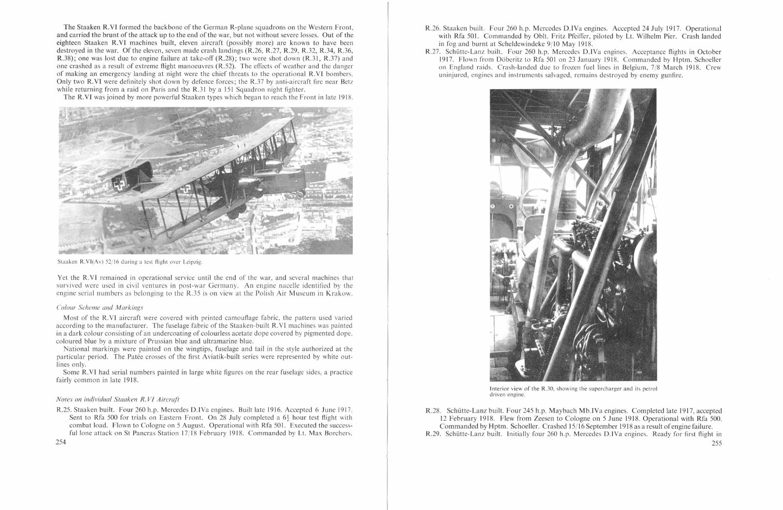
The Staaken R.YI formed the backbone of the German R-plane squadrons on the Western Front,and carried the brunt of the attack up to the end of the war, but not without severe losses. Out of theeighteen Staaken R.YI machines built, eleven aircraft (possibly more) are known to have beendestroyed in the war. Of the eleven, seven made crash landings (R.26, R.27, R.29, R.32, R.34, R.36,R.38); one was lost due to engine failure at take-off (R.28); two were shot down (R.3l, R.37) andone crashed as a result of extreme flight manoeuvres (R.52). The effects of weather and the dangerof making an emergency landing at night were the chief threats to the operational R.Y! bombers.Only two R.YI were definitely shot down by defence forces; the R.37 by anti-aircraft fire near Betzwhile returning from a raid on Paris and the R.31 by a 151 Squadron night fighter.
The R.Y! was joined by more powerful Staaken types which began to reach the Front in late 1918.
Staaken R.VI(Av) 52/16 during a test Aight over Leipzig.
Yet the R.Y! remained in operational service until the end of the war, and several machines thatsurvived were used in civil ventures in post-war Germany. An engine nacelle identified by theengine serial numbers as belonging to the R.35 is on view at the Polish Air Museum in Krakow.
Colour Scheme and Markings
Most of the R.Y! aircraft were covered with printed camouflage fabric, the pattern used variedaccording to the manufacturer. The fuselage fabric of the Staaken-built R.Yl machines was paintedin a dark colour consisting of an undercoating of colourless acetate dope covered by pigmented dope.coloured blue by a mixture of Prussian blue and ultramarine blue.
National markings were painted on the wingtips, fuselage and tail in the style authorized at theparticular period. The Patee crosses of the first Aviatik-built series were represented by white outlines only.
Some R.Yl had serial numbers painted in large white figures on the rear fuselage sides, a practicefairly common in late 1918.
Notes all individual Staaken R. VI Aircraft
R.25. Staaken built. Four 260 h.p. Mercedes D.IYa engines. Built late 1916. Accepted 6 June 1917.Sent to Rfa 500 for trials on Eastern Front. On 28 July completed a 6-t hour test flight withcombat load. Flown to Cologne on 5 August. Operational with Rfa 501. Executed the successful lone attack on St Pancras Station 17/18 February 1918. Commanded by Lt. Max Borchers.
254
R.26. Staaken built. Four 260 h.p. Mercedes D.lYa engines. Accepted 24 July 1917. Operationalwith Rfa 501. Commanded by Obit. Fritz Pfeiffer, piloted by Lt. Wilhelm Pier. Crash landedin fog and burnt at Scheldewindeke 9/10 May 1918.
R.27. Schutte-Lanz built. Four 260 h.p. Mercedes D.LYa engines. Acceptance flights in October1917. Flown from Doberitz to Rfa 501 on 23 January 1918. Commanded by Hptm. Schoelleron England raids. Crash-landed due to frozen fuel lines in Belgium, 7/8 March 1918. Crewuninjured, engines and instruments salvaged, remains destroyed by enemy gunfire.
Interior view of the R.30, showing the supercharger and its petroldriven engine.
R.28. Schutte-Lanz built. Four 245 h.p. Maybach Mb.1Ya engines. Completed late 1917, accepted12 February 1918. Flew from Zeesen to Cologne on 5 June 1918. Operational with Rfa 500.Commanded by H ptm. Schoeller. Crashed 15/16 September 1918 as a result ofengine failure.
R.29. Schi.itte-Lanz built. Initially four 260 h.p. Mercedes D.IYa engines. Ready for first flight in
255

February 1918. Four 245 Maybach Mb.lVa engines installed and other modifications made inMarch-April 1918. Fitted with upper-wing gun position. Accepted on I May 1918. Flew toRfa 501 on 3 May 1918. Crashed into trees while landing in fog at Scheldewindeke 9/l0 May1918.
R.30. Staaken built. Four 260 h.p. Mercedes D.IVa engines. Acceptance flights in October 1917.The constant need for hioher performance led to the development of several types of turbosuperchargers. The R.30 became the test-bed for a centrifugal supercharger built to the designsof Dipl.-Ing. W. G. oack by Brown-Boveri & Co. of Mannheim. A 120 h.p..Mercedes D.l[engine. located behind the starboard pilot, drove the supercharger which provided air to thecarburetters via conduits passing internally through the wing and into the nacelles. In September1918 the R.30 was also equipped with Helix adjustable-pitch propellers designed by Prof. H. J.Reissner. The pitch could be adjusted in flight by means of slotted cams that turned the metalsleeves into which the wooden propeller blades were fitted. The modified R.30 made its firsttest flight on 23 March 1918 and on 24 April attained an altitude of 19.357 feet, a remarkableimprovement over the 12,500 foot ceiling of standard R.VI machi~es. The maximum speed wasraised to 160 km.h., an increase of 30 km.h. over standard machInes.
On 24 May 1918 the R.30 was performing some test for Idflieg over Berlin. Hptm. Kruppand Lt. Offermann were at the controls; Dipl.-lng Noack and five other crew members werealso aboard. At 3300 metres altitude a wrist pin seized, which caused the connecting-rod tobreak and the piston to burst through the engine housing. This accident was later traced backto improper cooling of the crankca e oil due to modifications required by the ~uperch.arge?
Mercedes engine. A fire tarted which pread to the lower wing, but by descendIng rapidly Itwas possible to blowout these flames. However, long ribbon. of fire continued ~o s~ew fromthe nacelle. oack climbed over the lower wing to the burnIng nacelle and extingUished theblaze with a portable fire extinguisher. The R.30 landed safely.
In the early post-war period the R.30 was used for civil work with the name "Fletcher'sWorld" painted on each ide of the nose and rear fuselage. .
R.31. Staaken built. Four 260 h.p. Mercedes D.lVa engine. Accepted January 1918. OperatIOnalwith Rfa 500. Crashed in flames at Beugny 15/16 September 1918, as a result of enemy action.The British RAF War Diary ha the following statement concerning the loss of the R.31."Lt. S. C. Broome, 151 Squadron, saw a giant enemy machine held in our searchlights whichhe attacked firing 500 rounds altogether. The enemy aircraft bur t into flames and fell on ourside of the lines." Seeing that the aircraft was on fire, the commander. Lt. Wohlgemuht, ranthrough the aircraft and ordered the crew to bailout. Of the nine. only Lt. Wohlgemuht andone other person were saved by parachute.
R.32. Staaken built. Four 245 h.p. Maybach Mb.IVa engines. Acceptance flight on 24 January1918. Delivered to Rfa 50 I on 2 April 1918. Crash-landed in fog at Scheldewindeke andwas destroyed when its bombs exploded 9/10 May 1918.
R.33. Aviatik built. Four 260 h.p. Mercedes D.lVa engines. Accepted October 1917. Operationalwith Rfa 50 I. Crashed 15 October 1918.
R.34. Aviatik built. Four 260 h.p. Mercedes D.IVa engines. Completed December 1917. AtAltenburg airfield in January 1918 awaiting delivery to Front. Operation~1 with Rfa 501.Crashed near the Front on 21 April 1918, pos ibly as a result of enemy action. Seven crewkilled. Commanded by ObIt. Leistner.
R.35. Aviatik built. Four 260 h.p. Mercede D.IVa engine. Acceptance flight on 26 February 1918.Flown to Staaken to be fitted with turbo-supercharger. First test flights in June-July 1918.Weight increased to 9300 kg. empty and 12,875 kg. loaded. Further details are lacking.
R.36. Albatros built. Four 260 h.p. Mercedes D.IVa engines. R.36 "several weeks away fromcompletion" on 9 July 1917. Accepted in October 1917. Operational with Rfa 501 and believeddismantled after emergency landing on 7/8 March 1918.
R.37. Albatros built. Initially four 260 h.p. Mercedes D.IVa engines. Acceptance flight on 3February 1918. In March 1918 radio-telephone experiment were condu~ted betwe~n a groundstation and the R.37. Clear transmission of words, numbers and musIc wa attained over a
256
distance of 30 km. using a 500 watt transmission tube. R.37 trailed a 100 metre antenna. InApril 1918 Schutte-Lanz installed four 245 h.p. Maybach Mb.lVa engines. Flew to Rfa 500 on28 May 1918. Forced to land near Betz after hit by French anti-aircraft fire 1/2 June 1918.R.37 was returning from raid on Paris in company with another R-plane. Burned but notfully destroyed by crew, who escaped (later captured ?). Subject to widespread attention byAllied Press at the first R-plane to be inspected by the Allies.
R.38. Albatros built. Four 260 h.p. Mercedes D.IVa engines. Accepted 27 March 1918. Afterlosing course over Ruhr on delivery flight from Doberitz to Cologne to join Rfa 500, it crashedon an attempted emergency landing at Heisingen on 6 May 1918.
R.39. Staaken built. Four 245 h.p. Maybach Mb.1Va engines. Completed 18 July 1917. Accepted9 August 1917. Operational with Rfa 501. Crew con isted of Hptm. von Bentivegni commander and squadron leader; Lt. Frhr. von Lenz, first pilot, Lt. Buth, second pilot; Unteroffiziere Matern and Walter, engine mechanics; Klickermann, wireless operator; W. Teichert,machine-gunner and a fuel attendant (name Jacking).
The oreatest total bombs carried by any R-planc during its operational career is unknown, butthe R3'9 was probably champion, having dropped a total of 26,000 kg. in twenty bombing raidsas painted on the nose of the machine after the war. l
28 or 29 September 1917 Sheerness 26 May 1918 Abbeville6 December 1917 Margate 28 May 1918 Abbeville25 December 1917 Boulogne 31 May 1918 Etaples28 or 29 January 1918 London 30 June 1918 Amiens16 February 1918 London II July 1918 Doullens7 March 1918 London 13July1918 ArrasI April 1918 Boulogne 15 July 1918 Rouen21 April 1918 St. Omer 16 August 1918 Rouen9 May 1918 Dover 24 August 1918 Gravelines19 May 1918 Chelmsford 22 (?) 1918 Poperinghe
The only three 1000 kg. bombs dropped on England were carried by the R.39.R.52. Aviatik built. Initially four 300 h.p. Basse & Selve BuS.lVa engines. Completed May 1918.
Ground tests on 7 May 1918 showed Basse & Selve engines not fully reliable. Four 245 MaybachMb.lVa engines were installed. Acceptance flight on 5 June 1918. Delivered to Rfa 500 on20 June 1918 with acceptance guaranteed on 28 June provided certain defects were corrected. Atleast one, but possibly all, of the second Aviatik-built R.VI series had modified fuselages. Thecockpit was raised, moved farther to the rear and remained open. The front gun position wasraised to the level of the upper longerons. Operational with Rfa 500. Crashed and burned on11/12 August 1918 at Villers la Tour. Hptm. Erich Schilling and four members of the crewperished in the crash.
R.53. Aviatik built. Four 245 h.p. Maybach Mb.lVa engines. Completed July 1918. Assigned toRea Cologne as trainer, owing to insufficient performance, September 1918.
R.54. Aviatik built. Four 245 h.p. Maybach Mb.lVa engines. Expected delivery in October 1918pending decision whether to install a fifth Maybach engine in the nose. Probably never completed and scrapped in 1919.
1 For some reason this list did not tally with official records. The raid of 22/23 December 1917, during which theR.39 bombed the Thames eSluary, is not included, possibly because il was not a success. According to availablerecords, the R.39 bombed Dunkirk (the allernate targel) instead of Dover (Ihe intended target) on 9 May 1918.
257

SPECIFICAnONS
Staaken R.YlFlugzeugwerft G.m.b.H., Staaken, BerlinFour 260 h.p. Mercedes D.IYa enginesSpan, 42·2 m. (138 ft. 5t in.)Chord inner, 4·6 m. (I5 ft. I in.)Chord outer, 3·6 m. (11 ft. 10 in.)Gap inner, 4·6 m. (15 ft. 1 in.)Gap outer, 3·8 m. (12 ft. 5t in.)Incidence inner, 3t degreesIncidence outer, 2 degreesDihedral upper, noneDihedral lower, q. degreesBack stagger, 0-4 m. (l ft. 3t in.)Length, 22·1 m. (72 ft. 6 in.)Height, 6·3 m. (20 ft. 8 in.)Tail span, 9·0 m. (29 ft. 6 in.)
gap, 2·0 m. (6 ft. 6t in.)Propeller centres, 8·0 m. (26 Ft. 3 in.)Tractor propellers diameter, 4·26 m. (14 ft.)Pusher propeller diameter, 4·3 m. (14 ft. 1 in.)Wheel diameter, 1·02 m. (3 ft. 4 in.)Wings, 332 sq. m. (3572 sq. ft.)Wings, 2,050 kg.Fuselage, 1,450 kg.Tail unit, 400 kg.
ndercarriage, 800 kg.Accessories, 250 kg.Engines and tran mission, 2,730 kg.
Maximum speed, 135 km.h. (83'9 m.p.h.)Climb, 1000 m. (3281 ft.) in 10 mins.
2000 m. (6562 ft.) in 23 min.3000 m. (9843 ft.) in 43 mins.
Ceiling, 4320 m. (14,174 ft.) in 146 mins.Duration, 7-10 hrs.3000 litres (660 Imp. Gal.)Provision for nose, dorsal, ventral and upper-wing machine-gun positionsWestern Front with Rfa 500 and Rfa 501, 1917-November 1918
SPECIFICATlO S
T)pe:Manufacturer:Engines:
Fuel:Armament:Service Use:
Areas:Weights:
Performance:
Staaken R.Yl 30/16Flugzeugwerft G.m.b.H., Staaken, BerlinFour 260 h.p. Mercedes D.YIa enginesOne 120 h.p. Mercedes D.n to drive Brown-Boveri supercharger
Dimensions: Span, 42·2 m. (138 ft. 5t in.)Length, 22·1 m. (72 ft. 6 in.)Height, 6·3 m. (20 Ft. 8 in.)Propeller diameters, 4·5 m. (14 ft. 9 in.)
(Other dimensions same as Mercede -powered R.YI)Wings, 332 sq. m. (3572 sq. ft.)Empty, 8600 kg. (18,963 lb.)Loaded, 11,590 kg. (25,556 lb.)
Wing Loading: 35·0 kg. sq. m. (7,2 lb. 'sq. ft.)Pelj'ormance: Maximum speed, 160 km.h. (99-4 m.p.h.)
Climb, 1000 m. (3281 ft.) in 10 mins.2000 m. (6562 ft.) in 24 mins.3000 m. (9843 ft.) in 35 mins.
Ceiling, 5900 m. (19,357 ft.) in 102 mins.Serrice Use: None
7,680 kg. (16,934 lb.)1,980 kg. (4,366 lb.)1,800 kg. (3,969 lb.)
Empty,Fuel,Disposable load,
Type:Manufacturer:Engines:Dimensions:
Areas:Weights:
Weights:
Areas:Weights:
Fuel:Arrnalllent:Sen'ice Use:
Type:Manufactl/rer:Engines:Dimensions:
Loaded, 11,460 kg. (25,269 lb.)Wing Loading: 34·5 kg.jsq. m. (7'1 Ib.jsq. ft.)Pel!orlllance: Maximum speed, 130 km.h. (80'8 m.p.h.)
Climb, 1000 m. (3281 ft.) in II mins.2000 m. (6562 ft.) in 27 mins.3000 m. (9843 ft.) in 55 mins.
Ceiling, 3800 m. (12,467 ft.) in 150 mins.Duration, 7-8 hrs.2115 litres (465 Imp. Gals.)Provision for nose, dorsal, ventral and upper-wing machine-gun positionsWestern Front with Rfa 500 and Rfa 501, 1917-November 1918
SPECIFlCATlO S
Staaken R.YIFlugzeugwerft G.m.b.H., Staaken, BerlinFour 245 h.p. Maybach Mb.lYa enginesSpan, 42·2 m. (138 ft. 51 in.)Length, 22·1 m. (72 ft. 6 in.)Height, 6·3 m. (20 ft. 8 in.)
(Other dimensions same as Mercedes-powered R.YI)Wings, 332 sq. m. (3572 sq. ft.)Empty, 7921 kg. (17,465 lb.)Loaded, 11,848 kg. (26,125 lb.)
Wing Loading: 35·7 kg. 'sq. m. (7,3 lb. sq. ft.)
258
Staaken R.Yll
The Staaken R. Y II would appear on the imaginary Staaken family tree as a direct-line descendantof the earlier R.IY. There is little doubt that the R.Yll was built to capitalize on the success experienced with the R.IY configuration. The R.YlI employed the same engines and drive system, butdiffered very slightly from its predeces or in the following ways: upper-wing gun platforms wereomitted; radiator po itions were reversed; the engineer's compartment had open cockpits; the tailwas a single-bay structure and the undercarriage mounted eight wheels. A more subtle but mostimportant difference between the two aircraft wa that the fuselage of the R.YJL was about 4 feethorter. The slim rear fuselage of earlier YGO-Staaken R-plane had tendency to bend and twist
in flight; therefore, the length of the fuselage was reduced to increa e its stiffness. All later Staakenaircraft had the shorter fuselage configuration for that reason.
The R.YII, serial number R.14f15, wa accepted on 26 June 1917 after reaching an altitude of3800 metres in 100 minutes carrying a u eful load of 3600 kg. It was delivered to Idflieg (Rea) on3 July and assigned to Rfa SOlon 29 July 1917 after successfully completing a 6 hr. 30 min. practicemission with military load the day before. Jts ervice life was de tined to be hort, for it cra hed inthe following month. Here is what happened according to two eye-witness reports:
On Friday, 14 August 1917 the R.YII, commanded by officers of Rfa 500, was on its way to theFront. Although Rfa 500 did not arrive at Custinne until February 1918, it is believed that advanceelements of Rfa 500 may have been sent to the Front sooner. possibly to join Rfa 501 in the Ghent
259

Staaken R.YII 14/15.
area. It was decided to land on the airfield of Flieger Ersatzabteilung 5 (Fea 5) in Halber tadt forrepairs, and an aircraft was immediately di patched from Fea 5 to obtain replacement parts fromBerlin. On Sunday, 19 August 1917 repairs were completed and the crew of nine climbed aboardto take-off before a crowd composed of city officials, off-duty soldiers and curious citizen. TheR.Y!I headed into the wind down the airfield, at the far end of which was a low hill topped with afew tall pine trees. The Fea 5 target ranges were located on the far side of the hill, which droppedsharply into a rock-strewn ravine. At some 60-70 metres altitude the right wing seemed to drop.forcing the R.Yll into a starboard turn, and it was apparent to the spectators that something waswrong with the aircraft. The facile Halberstadt trainers would have had no difficulty in swingingaround to make a safe downwind landing, but the unwieldy R-planc was not capable of performingthis manoeuvre quickly enough. To the anxious spectators it seemed as if the R.YIf would either
Staaken R.Yll 14/15, with four-bladed tractor propeller.
260
clear the pine and make an emergency landing in the treacherous terrain on the far side of the hillor attempt to drop into the pine trees on the hill. The port engines were throttled back and the R.YIllost altitude, seemingly in preparation to land in the trees. For the moment, it appeared as if theexertions of the crew were going to be crowned with success after all.
Suddenly, a if the starboard engines had jerked to a stop, the right wing lurched towards theground and hooked a pine tree. With the added thrust of the port engines, the R.YH spin in a180 degree are, bounced off the hill and crashed into the ravine. The horrified spectator saw a blackpall of smoke slowly rise into the air.
Three badly burned crew members managed to escape and the starboard nacelle mechanic, who
Staaken R.YIJ 14/15 photographed before the fatal take-off erash at Halberstadt.
saw the mi hap coming, jumped free as the machine crashed. The wireless operator fought hi wayout of the flaming, twi ted wreckage and a machine-gunner was pulled from the crash by an alertand brave non-commissioned officer. Six aircrew died in the crash.
What actually happened aboard the R.YIl was told by the surviving flight mechanic. He statedthat the replaced leather clutch facing had been cleared for Right by the aircraft's chief mechanic, whoperished in the crash. Shortly after take-off the leather clutch burned through and the engine, robbedof its load and running at full speed, overheated and seized. Simultaneously, the other starboardengine, which was connected to the same gear-box, lost speed. The commander, noticing the difficulty, de perately signalled to the starboard mechanic, who interpreted the frantic hand waving a anorder to shut off the engine. The surviving crew members felt the engines were cut just as the R.Y!!was turning back to the airfield. The starboard wing dropped, hooked the pine tree and the fate ofthe R.YI! was sealed.
261

262
STAAKEN R.W SERIAL No. R.14/15
Staaken R.X IY 43/17 in its original form with four Austro-Daimler enginesarranged similarly to the R.Y!.
Staaken R.XIV
It required some two months to modify the fuselage to mount the fifth engine. According to therecord. the RA3 was ready for acceptance in July and the R.44 and RA5 were ready for their firstflights on 3 July and 10 July 1918 re pectively. The RA4 wa delivered in August and the RA5 inJuly 1918. These two machines differed from the RA3 in that the nacelle tractor propellers weredriven directly by the engine without benefit of the usual reduction gears.
]n his writings after the war, von Bentivegni, the experienced commander of Rfa 501, regretted thefact that no systematic attempt had been made to improve the performance of Staaken R-planes bycarefully refining the R.YI series. Instead of concentrating on weight reduction and streamlining.
s 263
]n late 1917 the Staaken R.YI was followed by an improved, more powerful version, designatedthe Staaken R.XIY. These aircraft were powered by four 350 h.p. Austro-Daimler twelve cylinderengines, the most powerful available at the time. Unfortunately, the Austro-Daimler engine provedunreliable and the hope of developing a "super" R.YI series was shattered.
The RA3/17, first of the new R.XIY series, was almost complete in February 1918. A March 1918Idflieg status report stated that this aircraft had a new seating arrangement for the pilot, consistingof an open cockpit on the upper fuselage decking to provide a broad field of view. It also providedan unencumbered commander's bomb aiming position in the nose. The engines were installed without reduction gears in order to obtain full-scale performance comparison with geared propellerson other R-planes, and the engine mount was redesigned to eliminate the recurrent failure of enginesupport truts on the R.Y! series. By March the RA3 had already flown many time. Its first flightin the acceptance programme took place on 11 April 1918, on wh ich the RA3 carried a 4020 kg.useful load to 3100 metre altitude in 91 minute. Soon after taking-off on the next day a connecting-rod broke in one of the rear engines. The Austro-Daimlers were replaced by four 300 h.p.Bas e & Selve BuS.IYa engines, and was reported once more ready for flight testing on 10 May1918. However, the new unproven BuS.IYa engines showed a propensity for piston seizure andwere in their turn removed from both the RA3 and the R.44 (which had been expected to makeits first flight on 3 May J918). The final installation con isted of five 245 h.p. high-compressionMaybach Mb.IYa engines. Since the R.XIYweighed some 2000 kg. more than the R.Vr, an additionalengine mounted in the no e wa necessary to at least keep performance on a par with the R.Y!.
8,923 kg. (19,675 lb.)2,140 kg. (4,719 lb.)1,890 kg. (4,167 lb.)
Empty,Fuel,Disposable load,
SPECrFICATlONS
Staaken R.YllFlugzeugwerft G.m.b.H., Staaken, BerlinTwo 160 h.p. Mercedes D.lIr enginesFour 220 h.p. Benz Bz.lY enginesSpan, 42·2 m. (138 ft. 5t in.)Length, 22·1 m. (72 ft. 6 in.)Height, 6·8 m. (22 ft. 3t in.)Tractor propeller diameter, 4·2 m. (13 ft. 9 in.)Pusher propeller diameter, 4·1 m. (13 ft. 6 in.)Wings, 332 sq. m. (3572 sq. ft.)Wings, 2,350 kg.Fuselage, 1,450 kg.Tail unit, 400 kg.Accessories, 250 kg.Undercarriage, 900 kg.Engines and transmissions, 3,573 kg.
Loaded, 12,953 kg. (28,561 lb.)Wing Loading: 39·0 kg.jsq. m. (8'0 Ib./sq. ft.)Performance: Maximum speed, 130 km.h. (80,9 m.p.h.)
Climb, 1000 m. (2381 ft.) in 12 mins.2000 m. (6562 ft.) in 25·5 mins.3000 m. (9843 ft.) in 50 mins.
Ceiling, 3850 m. (12,631 ft.)Fuel: 3140 litres (691 fmp. Gals.) in twelve 245 litre tanks
Gravity tank, 155 litres (34,1 Imp. Gals.)Oil, 171 litres (37,6 Imp. Gals.)
Sen>ice Use: one
Dimensions:
Areas:Weights:
Type:Manufacturer:Engines:
Colour Scheme and MarkingsThe R.YJI had a buff finish reminiscent of the early YGO types and carried the Patee cross insignia
with white edges on wings, fuselage and tail.

newer machines such as the R.XIY embodied a purposeless increase of fuselage size. weight and drag.which in themselves taxed performance and to some extent nullified the effect of an additional engine.
On the other hand, after comparing his experiences with both four- and five-engined StaakenR-planes, von Bentivegni was convinced that the disadvantages of the nose engine had been overemphasized and its advantages minimized. Jt should never be forgotten, he said in 1920, that an
Staaken R.XIV 43/17 powered by five Maybach Mb.IVa engines.
additional engine offered increased reliability, the most important factor in R-plane design. Theproblem of the high landing gear, which had been responsible for the elimination of the nose enginein the first place, was solved by simply keeping it short. This was made possible by design changeswhich allowed a normal "tail-down" ground attitude.
Among the disadvantages discussed by von Bentivegni was the proximity of the fuselage engine tothe main fuel tanks, a factor that increased the fire hazard in event of a crash. It was his opinion.however, that this danger was more than compensated for by the increased reliability provided by the
Staaken R.XIV.
additional engine. An unexpected problem discovered during operational service was that of unavoidable vibrations of the nose engine. These vibrations had a very deleterious effect on the moredelicate instruments installed in the later Staaken machines, particularly on sensitive electric wiringa nd con nections.
According to von Bentivegni, the efficiency of the small-diameter ungeared propellers was hopelessly inadequate, and he considered this modification a total failure. Furthermore, the R.XIY serieshad strengthened airframes to house the more powerful Austro-Daimler engines. The resultant
264
increase in weight was yet another factor which lowered the performance of these machines. Not untilthe last months of the war were R.XIY hortcomings eliminated with the advent of the improvedR.XIYa series.
The typical Staaken wing was retained on the R.XIY with exception of a 1·5 degree sweepback ofthe outer wing panels; a trailing edge cut-out above the propellers and the fitting of balanced aileronswhich were neatly faired into the wingtip outline. Upper-wing gun positions were installed slightlyoutboard of the nacelles and between the nacelle struts rather than behind as in the R.YJ.
The nacelles, somewhat slimmer than those on the R.YI, were mounted higher in the wing gap.and the nacelle strut arrangement was considerably modified. The R.XIY machines were generallyfitted with propeller spinners. The R.45 was at one time equipped with large-diameter four-bladedpusher propellers. whose blades were unusually narrow. The large spinner of the nose engine andthe aluminium engine cowling provided a smooth entry to the fuselage, broken only by the protrudingradiator and the auxiliary landing gear.
Staaken R.xIV 45 17 with the pilot's cockpit placed behind the wings.
As in the earlier Staaken giants, the flight engineer's compartment was located directly behind thenose. followed by the enclosed navigation and commander's cabin, which also contained the bombaiming apparatus that may have been hung externally during u c. Then came the large open pilots'cockpit located in the upper decking. The open cockpit was a definite departure from the closedcockpit of the R. VI and demonstrated the crews' preference to fly in "open air" unhampered bywindow reflection. dazzle and condensation and the strange feeling of being shut in from the rushingair.
By this time the Germans had tested and perfected a parachute that was being issued to serviceaircrews as it became available. The R.XIV carried a full complement of parachutes stored in externalfuselage compartments with short "hook-up" lines running to each of the crew stations.
The armament carried by the R.XIV consisted of six machine-guns distributed as follows: one eachin the upper-wing gun positions and two each in the dorsal and ventral positions. The increase in thenumber of machine-gun over the R.VI. which generally carried four (sometimes five) guns, was areflection of the intensified night-fighter activity of the Allies.
A novel optical communication system developed by the Karl Bamberg firm was tested on theR.44. The technique con isted of writing a message on a frosted gla and then projecting the image
265

OJ.
h3ihhtTtdS-.... _ fur.
--R. XISl lI. R. xsz::STAAKEN
Cl
Slaaken R.XIV.
through prisms and len es on to an opaque remote-reading surface. The device worked well on theground, but failed under vibration, which blurred the message to illegibility.
The R.45 was fitted with a cockpit located behind the trailing edge of the wings in a manner similarto the AEG R. 1. The purpose of this configuration was to provide a better view of the undercarriageand ground while landing. During tests at Staaken the wing-root panels were left open in order toimprove the downward view. By the time the R.45 left for the Front these panels had been coveredand the narrow chord four-bladed propellers replaced by the more usual two-bladed propeller.
On 9 August 1918 the R.45 left Staaken for Hanover, and on the next day continued to the Rfa500 airfield at Morville. Lt. von Plotz and Lt. Steinhauser were the officers aboard R.45 when,accompanied by R.31, it took-off to bomb Ie Havre on 15 September 1918. After the raid, theR.45 received a wireless message warning it not to return to Morville because enemy aircraftwere over the airfield and the landing lights would not be turned on. But the fuel supply wastoo low to continue on, forcing the commander to make the decision to land. The wirelessoperator notified the airfield and asked that ground personnel signal with flashlights. The firstand second landing attempts failed, and it was not until a number of flares had been shot-offthat enough illumination was provided to enable the pilots to touch down on the airfield. Inspite of the emergency illumination, the R.45 missed the runway, which the crew noticed by thesevere shaking they received. Suddenly, in the darkness, the left wing struck an obstruction, thenthe right wing and the R.45 stood still. In the morning the damage was inspected and it wasfound that the left wing had hit a water-tank wagon and a large portable ladder; the right wingsome construction material and the roof of a peasant house. This fortunate accident saved the266

fall was seen for miles, even by pilots who were bombing IS miles away and on the German sideof the lines. Five of the crew attempted to bail out, but all seven crew members were killed.
On hitting the ground, one of the bombs exploded, completely wrecking the fuselage. French andBritish aviation experts scrutinized the remains carefully, finding, surprisingly enough, two Lewismachine-guns (and also two Parabellum) in the wreckage. An intere ting Briti h Intelligence comment that "little regard was paid to saving weight in the design of fittings throughout the machine,some fittings being more than ordinarily heavy and cumbersome, even for such a large machine",supports von Bentivegni's comments as noted earlier.
On II February 1919 British forces occupying the Rhineland found the RA4 abandoned onthe airfield at Cologne. The machine had been stripped of fabric and engines, and only the gauntskeleton remained.
As a sideline to this history, it should be noted that just prior to the delivery of the last Zeppelinairship built at Staaken (the L.64), the name of the Zeppelin concern was changed again. On25 January 1918 the Luftschiffbau Zeppelin G.m.b.H. and the Flugzeugwerft G.m.b.H. merged tobecome the Zeppelin-Werke G.m.b.H. Contemporary photos show cavernous airship hangarsserving as construction and a sembly areas for Staaken R-planes.
Colollr Scheme and Markings
The R.XIV machines were finished overall in printed camouflage fabric. The standard Latin crosswas carried on wings, fuselage and tail. The serial numbers were painted in large white figures on therear fuselage section.
lives of sixty men who were sleeping in a barracks directly in the path of the careering bomber.It is doubtful if the RA5 was repaired in time to participate in further bombing raids before theArmistice.
The RA3 and RA4 also saw service on the Western Front during the autumn of 1918. TheRA3 has been remembered as one of two R-planes confirmed as shot down by an opposing
STAAKE'\ ".m 5E~IAL No R.4-5. EXPERIMENTAL RE·LOGATION OF THE CONTROL POSITION.
aircraft. On the night of 10/11 Augu t 1918 the RA3 of Rfa SOl was on a bombing missionwhen it was lit up by searchlights over Talmas. According to the records, it was an easy targetdue to the large amount of exhaust smoke. The heavy concentration of lights attracted fourBritish pilots to the scene, one of whom was Capt. A. B. Yuille of 151 Squadron R.A.F. Recently
Wrcckage of the taakcn R.44 on the Colognc airficld. February 1919.
transferred to France from Home Defence duties in England, 151 Squadron was a special nightfighter unit flying Sopwith Camels. The RA3 was attacked from all sides. Yuille closed to about25 yards, but did not fire a shot until he had settled well below and behind the bomber's tail.Yuille then opened with three short bursts and put one engine out of action. The next two burstsset the fuselage afire around the rear gunner's cockpit. The RA3 started going down, with itsnose down and turning on one side. It then dived more steeply, burst into flame and one set ofwings dropped off. Yuille followed the burning mass down and watched it crash. The bomber's268
Tl'pe:M anujacrurer:Engines:Dimensions:
Areas:WeighTS:
Performance:
Fuel:A rmomenT:Sen'ice Use:
SPECIFICATJO S
Staaken R.XlVZeppelin-Werke G.m.b.H., Staaken, BerlinFive 245 h.p. Maybach Mb.lVa enginesSpan, 42·2 m. (138 ft. 5t in.)Chord inner, 4·6 m. (15ft. 1 in.)Chord outer, 3·6 m. (I I ft. 10 in.)Gap maximum, 4·6 m. (15 ft. 1 in.)Gap minimum, 3·8 m. (12 ft. 5t in.)Dihedral upper, noneDihedral lower, 2 degreesSweepback, It degreeIncidence inner, 3t degrees1ncidence au tel', I degreeLength, 22·5 m. (73 ft. 10 in.)Height, 6·3 m. (20 ft. 8 in.)Tractor propeller diameter, 4·1 m. (13 f1. 5~ in.)Nacelle tractor propeller diameter, 3·25 m. (10 f1. 7t in.)Nacelle pusher propeller diameter, 4·3 m. (14 f1. I in.)Wheel diameter, 1·3 m. (4 ft. 3 in.)Wings, 334 sq. m. (3594 sq. f1.)Empty, 10,350 kg. (22,822 lb.)Loaded, 14,450 kg. (31,862 lb.)Maximum speed, 130 km.h. (80,8 m.p.h.)Climbing peed, 100 km.h. (62,1 m.p.h.)Climb with load, 3000 m. (9843 f1.) in 70 min.Ceiling, 3700 m. (12,140 f1.)Range with 1000 kg. bombs, 1300 km. ( 08 miles)3150 litres (693 Imp. Gals.)Provision for dorsal, ventral and two upper-wing machine-gun positionsWestern Front with Rfa 500 and Rfa 501 August-November 1918
169

Staaken R.XIVa
The Staaken R.XlVa serie comprised the last R-planes to be built by Staaken during the war.These aircraft were delivered later than the Staaken RXV series.
The R.X1Va, as the designation indicates, was an improved version of the R.XIV, modified toincrea e its rate of climb and operating ceiling with increased war load. To achieve this end, reductiongearing was again fitted to all engines and the weight of the machine was considerably reduced byinternal structural changes and removal of upper-wing gun mounts and the bomb-bay fairing. Thedimensions of the fuselage and nacelles were reduced, which resulted in a small increase of speed.
onc
Staaken R.XIVa 69/18 with a visiting Argentine commission at Doberitz.
The only other obvious change was that the elevator surfaces were balanced, making the R.X1Vathe first Staaken machine to have all its control surfaces balanced.
fdflieg ordered four R.XlVa machines from Staaken, and these received the erial number R.69to R.72. Due to the production programme it was not possible to include all the modifications.particularly weight reduction, on the R.69; however, the R.70 was to be a fully lightened ver ion.The R.69, delivered on 19 October 1918, did not see any front-line service. The R.70 and 71 wereprobably completed in late 1918 or early 1919, and it is not known if the R.72 was finished.
In 1919 the R.69 wa chartered by the Ukrainian Government to fly money into the Ukraine, andwa eized by the Inter-Allied Control Commission when it landed on a return flight at Aspern nearVienna. It was subsequently turned over to Italian authorities. The R.70 and R.71 were also flownbetween Germany and the Ukraine to deliver currency. On 19 September 1919 the R.70 was confiscated by the Roumanian Government when it made a forced landing in Bessarabia. The R.71crashed and burned of unknown causes in the forest of Ratibor during the summer of 1919.
Schutte-Lanz wa al 0 given a contract to build three RXIVa machines numbered R.84 to R.86at the cost of 600,000 marks each, but none were completed prior to the end of the war. Furtherdetails may be found in the Schi.itte-Lanz chapter.
270
STAAKEN R.XTIlA. 5ERIALNo. R.69 TO R.72
Staaken RXIVa 69/18 in the Ukraine.
Staaken R.XIVa 70/18 on the Hundsfeld airfield near Breslau.
271

Staaken RXIVa (SchUl) 84/18 prior to the fitting of propeller spinners.
Areas:
Weights:
Performance:
Armament:
Wings, 334 sq. m. (3594 sq. ft.)Tailplanes, 32-4 sq. m. (349 sq. ft.)Elevators, 9 sq. m. (97 sq. ft.)Fins, 9·2 sq. m. (99 sq. ft.)Rudders, 3·6 sq. m. (39 sq. ft.)Ailerons, 7·15 sq. m. (77 sq. ft.)Empty, 10,000 kg. (22,050 lb.)Loaded, 14,250 kg. (3J,421 lb.)Maximum useful load, 5000 kg. (11,025 Ib)Maximum speed, 135 km.h. (83'9 m.p.h.)Climbing speed, 95 km.h. (59 m.p.h.)Climb, 1000 m. (3281 ft.) in 7 mins.
3000 m. (9843 ft.) in 45 mins.Ceiling, 4500 m. (14,764 ft.)Range with 1000 kg. bombs, 1300 km. (808 miles)Provision for dorsal and ventral machine-gun positions
The completed Staaken RXIVa (SchUl) 84/18.
Staaken R.XV
The Staaken R.XV series remain something of a mystery, for virtually no technical informationexists to explain why these machines, though almost identical to the R.XLV type, received a differentdesignation. The R.XV had the same engine configuration as the R.XIV and closely resembled the
C%/lr Scheme and Mark ings
The R.XIVa machines were finished overall in printed camouflage fabric. The standard Latincross was carried on wings, fuselage and tail. The serial numbers were painted in large white figureson the rear fuselage section. These machines continued to carry the Latin cross during their post-waropera t ions.
Tl'fJe:/vi anll/actll!"e!":Engines:Dill/ensions:
272
SPECIFICATIONS
Staaken R.XIVaZeppelin-Werke G.m.b.H., Staaken, BerlinFive 245 h.p. Maybach Mb.IVa enginesSpan, 42·2 m (138 ft. 5i in.)Length, 22·5 m. (73 ft. 10 in)Height, 6·3 m. (20 ft. 8 in.)
Staaken R.XV 47 17.
latter in outward appearance. ]t is probable that the R.XY was basically an R.XIV airframe modifiedto improve the performance by lightening the airframe. The airframe does show signs of greaterattention to detail and streamlining; for instance, the nose cowling had more refined contours. Ifany other refinements were made they have not been recorded. There is no doubt, however, about theR.X V designa tioll. The official Germa n eq ui pment ta bles for R-planes specified six mach ine-gunsfor this type.
The RA6/17. the first of three R.XY machines completed, was reported as being ready for itsmaiden flight on 25 July 1918 and was delivered in August. A contemporary status report statedtha t the RA7 and R 048 were expected to be completed on 3 Augllst and 13 AlIgu t respecti vely :they were both accepted on I September 1918. At least two of these aircraft saw service with R-planesquadrons on the Western Front.
273

Slaaken RXV 48/17.
A victor's poil, the complete R.47 was shipped to Japan, and the Inter-Allied ControlCommission team that inspected the Staaken factory found the R.48 there in 1919. It may havebeen parts of this aircraft that were sent to the Isle of Grain for study.
Three machines powered by the Bz. VI engine were ordered under the designation Staaken R.XVI(Av) R.49 to R.5 [. With the exception of the wing and nacelles, the airframe wa outwardly identicalto the R.52 series.
The chief characteristic of the R.XVI was the finely streamlined nacelle, the diameter of whichwas enlarged to accommodate the Bz.VI engine. The engine was mounted in the rear of the nacelleand drove a two-bladed pusher propeller through reduction gears. Initially the BuS.IVa engine wasin talled in the front of the nacelle behind a massive spinner. Recurrent problems made it necessaryto replace it by a smaller 220 h.p. Benz Bz.IV engine. Judging from the size of the tractor propellers,it seems the Bz.IV engine wa not equipped with reduction gears.
The nacelles were mounted in the wing gap by fore-and-aft splayed struts similar to those on theStaaken R.XIV. As usual, the radiators were mounted on struts above the engines. The Bz.VIengines each had two radiators, one for each bank of six cylinders. Large conspicuous oil coolerswere located under the belly of each nacelle.
The wing area of the RXVI wa increased slightly, the trailing edge propeller clearance indentationswere eliminated and the wing was strengthened, but in all other respects the wing structure remainedsimilar to the R.XIV.
Slaaken R.xvr (Av) 49/17.
Staaken RXVZeppelin-Werke G.m.b.H., Staaken, BerlinFive 245 h.p. Maybach Mb.IVa enginesSimilar to Staaken R.XIVSimilar to Staaken R.XIVUnknownUnknownSimilar to Slaaken R.XIV
SPECIFICAnONS
Colour Scheme and Markings
The RXV machines were finished overall in printed camouflage fabric. The standard Latin crosswas carried on wings, fuselage and tail. The serial numbers were painted in large white figures onthe rear fuselage section.
Type:Manufacturer:Engines:Dimensions:Areas:Weights:Performance:Armament:
Staaken R.XVI
In its quest for ever greater R-plane performance and load-carrying ability, Jdftieg placed an orderfor twenty 530 h.p. Benz Bz.VI twelve cylinder V-block engines in May 1917. Early in 1918 Benz &Co. A.G. in Mannheim had brought the development of their powerful engine to a point wherelimited quantities were available. The Aviatik concern was given the task of fitting the e engines intothe basic Staaken R.VI airframe. Aviatik, rather than Staaken, was selected because the Staakenfirm was already fully committed to the development of all-metal aircraft. Aviatik possessed ampleexperience for the job, having already built the R.33 to R.35 and R.52 to R.54 under licence.
274
Staaken R.XVI (Av) 50/17.
275

c,
-0--
The Staaken R.XVr (Av) 50/17 in flight.
By May 1918 the Bz.VI engine and reduction gear bench tests were well under way, and delivery ofthe R.49 wa expected at the end of June. The military acceptance tests for the engine and gearingcalled for 10 hours running at an output of 500 h.p. at 1400 r.p.m. The status report for September1918 states that the initial Aights of the R.49 were most satisfactory. With a useful load of 4250 kg..an altitude of 4300 metres had been reached in 53 minutes, and no trouble was experienced withthe engines. The following month the R.49 underwent its acceptance Aights, during which oneengine-out trials were conducted. During one of its Aight tests it landed heavily, and the resultant shockcollapsed the landing gear, which tore through the lower wing as the aircraft came to re t on itsbelly. The lower wing suffered severe damage, and it is doubtful if the R.49 was rebuilt.
The R.50 was three-quarters complete on 12 January 1919, and was expected to be ready fornight on 15 February 1919. It was not completed as a bomber but modified into a civil machine andcon equently differed in several respect from the R.49. The blade of the tractor propellers wereincreased in size. an indication that the engines were fitted with reduction gears. To save weight. theupper-wing gun mounts. ladders and bomb-bay fairing were removed.
The R.50 was proudly di played by the Aviatik concern with the name "Aviatik" emblazoned inmassive white letters across the underside of the lower wing and fuselage. Owing to conditionsexisting at the time, Aight testing was inconclusive and the R.50 made its last flight in November1919 when it was Aown to Doberitz for storage. The third R.XVI, the R.51, also three-quarterscompleted in January 1919 was never finished, according to Aviatik chief engineer LudwigMaurer. who wrote that only two R.XVI machines were constructed.
The R.XVI repre ented the ultimate development of the standard Staaken R-plane airframe. Withits 1500 horse-power. the R.xVI wa the most powerful aircraft built and flown by the Germansduring the war. It is unfortunate that treaty limitations prevented a full investigation of the machine'spotential civil capabilities.
C%ur Scheille alld Markings
The R.49 was finished overall in printed camouAage fabric; the polygons were rather small and therepeat pattern readily discernible. The standard Latin cross was carried on wings. fu elage and tail.The R.50 had chord-high letters "Aviatik" painted across the underside of the lower wing andfuselage. The aircraft carried no national markings.
276
STAAKEN R.xsz:r IAv) SERIAL No. R4-9
OJ.
:" I [Er:l:rfiIijSo... '" fur.

Type:Manufacturer:Engines:
Dimensions:
Areas:Weights:
Performance:
Armament:Service Use:Cost:
SPEClFlCATlONS
Staaken R.XVIAutomobil & Aviatik A.G., Leipzig-HeiterblickTwo 530 h.p. Benz Bz.VI pusher enginesTwo 220 h.p. Benz Bz.lV tractor enginesSpan, 42·2 m. (138 [t. 5t in.)Length, 22·5 m. (73 [t. 10 in.)Height, 6·5 m. (21 [t. 4 in.)Wing, 340 sq. m. (3658 sq. [t.)Empty, 10,400 kg. (22,932 lb.)Loaded, 14,650 kg. (32,303 lb.)Maximum speed, 130 km.h. (80,8 m.p.h.)Ceiling, 37LO m. (12,172 [t.) in 76·5 mins.Provision for nose, dorsal, ventral and two upper-wing machine-gun positionsNone530,000 marks
Staaken L Staaken L on floats and carrying the nickname "Lisbet" in the Staaken hangar at Potsdam.
279
The German Navy's interest in R-planes did not wane with the destruction of its RML.1 ; on thecontrary, Naval authorities actively continued to pursue the development of R-planes for use innaval warfare. As early as December 1916, Rear Admiral Philipp, Befehlshaber del' Luftstreikrafte(Chief of Air Forces), had outlined future naval requirements and had established preliminaryspecifications as guidelines for aircraft manufacturers.
The reason for the increased emphasis on R-seaplanes was that English aircraft were verysuccessful in attacking German airships. This resulted in a standing order that airships were toremain above 13,000 feet, which precluded their use as low-level submarine, shipping and minespotters. Taking this into account, Admiral Philipp recommended the development and evaluationof less-vulnerable R-seaplanes of the flying-boat and floatplane category. Admiral Philipp listed theR-planes' advantages over the airship, as follows: they could fly faster, carry greater defensivearmament, did not require huge hangars, could be readied for flight in a fraction of the time, usedless personnel and were cheaper to build. The preliminary specifications for three classes of giantseaplanes were outlined in Admiral Philipp's memorandum of 26 December 1916:
Staaken L fitted with a wheeled undercarriage for delivery from Staaken to the companyseaplane facility at Potsdam.
278
J. Reconnaissance Aircraft
(a) 1200 h.p. (four engines).(b) Five crew, four machine-guns, wireless equipment, 100 kg. bombs, 10-12 hours duration.(c) Rapid climb not required.(d) Slow climb with one engine stopped, must maintain altitude on two engines.(e) Take-off capability required in dead calm, wind and sea.
Take off in "Seegang 3" (wave height -.t-2 metres, wind force 4)Landing in "Seegang 6" (wave height 5-7 metres, wind force 7-8)
II. Bomber Aircraft (four engines)
(a) Five crew, five machine-guns, wireless equipment, 1000-1800 kg. bombs, 5 hours duration.(b) Minimum speed 130 km.h.(e) Good climb.(d) As in led).(e) As in ICe).
HI. Torpedo Aircraft (four engines)
(a) Five crew, two machine-guns, wireless equipment, one G-Torpedo (1020 kg.), 8 hoursduration.
(b) Maximum speed 130 km.h., minimum speed 80 km.h.(e) Rapid climb not required.(d) Slow climb with one engine cut. Must maintain altitude on two engines after torpedo has
been dropped and with 2 hours fuel aboard.(e) As in I(e)
~dmiral Philipp went on to say; "Most urgent is the development of the reconnaissance R-plane."ThIS statement was supported by a fair number of letters and notes in which high-ranking navalofficers pressed for the immediate development of large reconnaissance aircraft for low-altitudespotting duties which the airship could no longer fulfil.
In a document dated 10 February 1917 Philipp defines more precisely the future role of the R-seaplane. Because the R-seaplane will be required to fly but 500 metres over the water, Philipp said, itmust be endowed with greater reliability than any other type of aircraft, as a slight mechanical failureco.uld force it down .far out at sea. The projected task was Jow-Ievel reconnaissance, primarily formll1e-spottll1g, ShIpplllg control and anti-submarine duties.
T
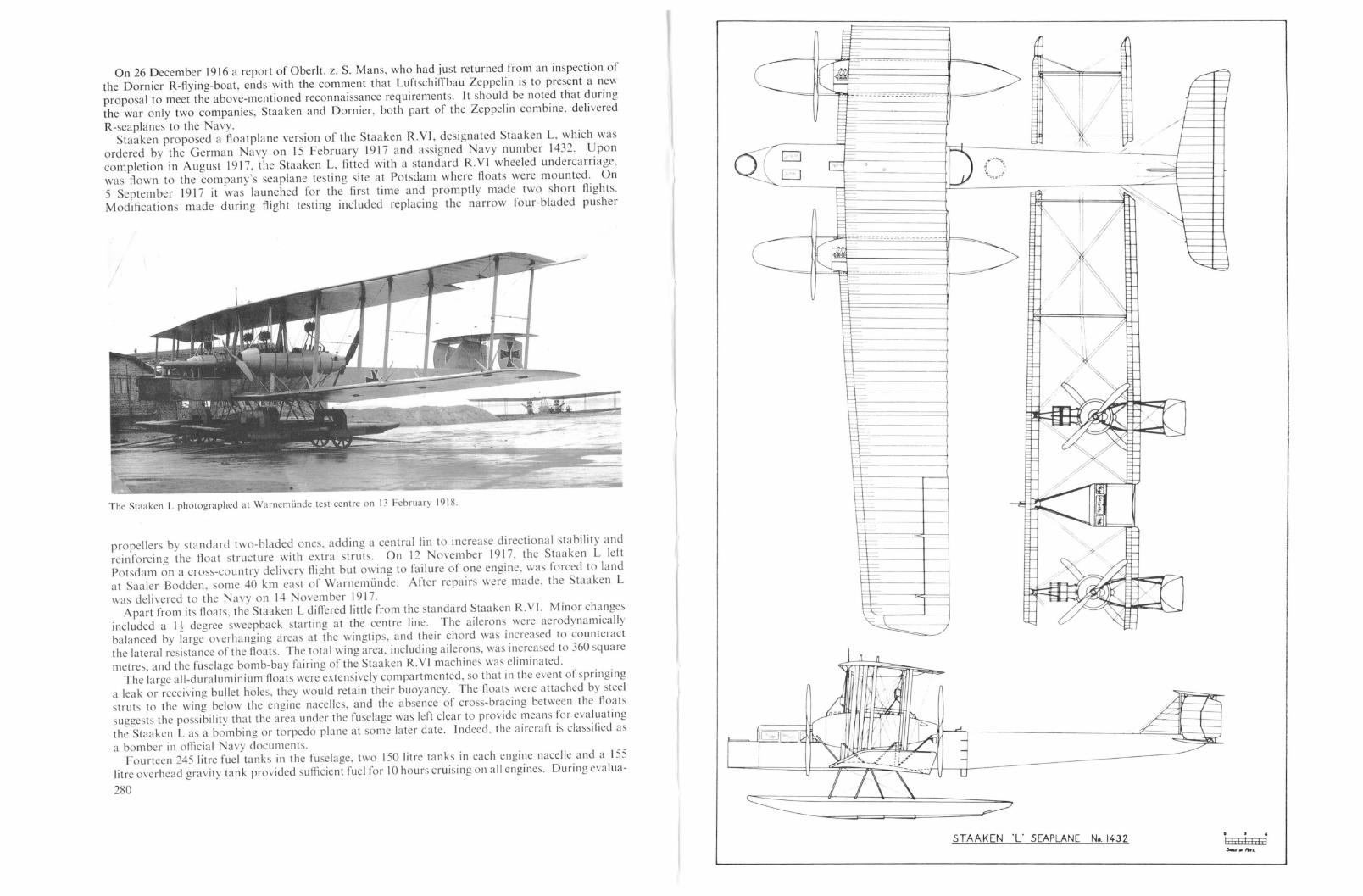
/'i.J---4--j/'
Ir
-~V
-~
!
e=-.-.-------\
--- - -----
--
~- -._-
-f--
-----------------
-
\=1=t--
-j;;-
--~
n n
jl III
L.]-----------
=
I-
Ll----------
t-I-- . _r-l- . _
=-----------1
1==
c::::: _ 0
oo
~-----=======~~
propellers by standard two-bladed ones, adding a central fin to increase directional stability andreinforcing the float structure with extra struts. On 12 November \917, the Staaken L leftPotsdam on a cross-country delivery flight but owing to failure of one engine, was forced to landat Saaler Bodden, some 40 km east of Warnemunde. After repairs were made, the Staaken Lwas deli vered to the Navy on 14 ovem ber 1917.
Apart from its floats. the Staaken L differed little from the standard Staaken R.Y£. Minor changesincluded a l-t degree sweepback starting at the centre line. The ailerons were aerodynamicallybalanced by large overhanging areas at the wingtips, and their chord was increased to counteractthe lateral resistance of the floats. The total wing area, including ailerons, was increa ed to 360 squaremetres. and the fuselage bomb-bay fairing of the Staaken R.YJ machines was eliminated.
The large all-duraluminium floats were extensively compartmented, so that in the event of springinga leak or receiving bullet holes, they would retain their buoyancy. The floats were attached by steelstruts to the wing below the engine nacelles, and the absence of cross-bracing between the floatssuggests the possibility that the area under the fuselage was left clear to provide means for evaluatingthe Staaken L as a bombing or torpedo plane at some later date. Jndeed. the aircraft is classified as
a bomber in official avy documents.Fourteen 245 litre fuel tanks in the fuselage, two 150 litre tanks in each engine nacelle and a 155
litre overhead gravity tank provided sufficient fuel for 10 hours cruising on all engines. During evalua-
280
On 26 December 1916 a report of Oberlt. z. S. Mans, who had just returned from an inspection ofthe Dornier R-f1ying-boat, ends with the comment that Luftschiffbau Zeppelin is to present a newproposal to meet the above-mentioned reconnaissance requirements. It should be noted that duringthe war only two companies, Staaken and Dornier, both part of the Zeppelin combine. delivered
R-seaplanes to the avy.Staaken propo ed a floatplane version of the Staaken R.YI, designated Staaken L, which was
ordered by the German avyon 15 February 1917 and assigned avy number 1432. Uponcompletion in August 1917, the Staaken L, fitted with a standard R.Yl wheeled undercarriage,was flown to the company's seaplane testing site at Potsdam where floats were mounted. On5 September 1917 it was launched for the first time and promptly made two short flights.Modifications made during flight testing included replacing the narrow four-bladed pusher
The Staaken L photographed at Warnemlinde test centre on 13 February 1918.
STAAKEN 'L" SEAPLANE No. 1432

Areas:Weights:
Type:M anu!acturer:Engines:Dimensions:
tion tests a technique was developed to extend the range by cruising on only three engines, providedenough fuel had been consumed to reduce the machine's weight.
The Staaken L was equipped with Navy-developed transmitting and receiving gear, which waspowered by a propeller-driven generator mounted above the wireless operator's compartment incontrast to the Army wireless equipment, which required a motor-driven generator. The aircraftwas assigned to the Seeflugzeug-Versuchs-Kommando (Seaplane Testing Command) in WarnemLindefor extensive te ts and evaluation over a wide range of sea and weather conditions.
A special wooden hangar was designed and constructed by Firma Carl Tuchscherer in 1917 tohouse the Staaken L. Built on piles over the water, the hangar was unique in that the door was only27·5 metres wide. A larger door capable of withstanding high seas and winds would have beendifficult to install and maintain. Therefore, to keep the door small, it was decided to bring the aircraftinto the hangar sideways, using a novel technique. Experiments had proved the impracticability ofbringing an aircraft into a hangar sideways under even the slightest wind and wave conditions.Consequently, Tuchscherer proposed and built a pivoted, floating pier extending at right anglesfrom one side of the hangar opening. The aircraft's left float was secured to the floating pier. Thenthe pier was swung around, its pivoted end turning the aircraft sideways through the opening intothe hangar as it completed a 180 degree arc. The hangar trusses were capable of supporting a 12,000kg. load, permitting the Staaken L to be lifted for repairs to the floats. A second, much larger hangarcapable of housing four R-planes was under construction at the close of the war.
The Staaken L crashed over Warnemunde on 3 June 1918 killing the pilot, Lt. Haller and thecrew.1 Very little is known regarding the outcome of the Staaken L evaluation te ts. It was not asstable on the water as the Dornier R-f1ying-boat . The wing tips would touch the water at a 7 degreeheel, whereas the flying-boat required a 14 degree heel. Nevertheless, it was a proven design thatStaaken had built in quantity, and it could be produced in less time than the all-metal Dornierflying-boats. Six further Staaken R-seaplanes based on the Staaken L were ordered by the Navy.
Colour Scheme and Markings
The Staaken L was finished overall in a light colour and carried the Patee cross insignia outlinedin white on wings, fuselage and tail. Contrary to usual Naval practice, the serial number was notpainted on the fuselage. At Potsdam the Staaken L was named "Lisbet" and this name waspainted in black capital on both sides of the fuselage.
SPECIFICAnONS
Staaken LFlugzeugwerft G.m.b.H., Staaken, BerlinFour 260 h.p. Mercedes D.IVa enginesSpan, 42·2 m. (138 ft. 51 in.)Maximum Chord, 4·53 m. (14 ft. 10 in.)Maximum Gap, 4·55 m. (14 ft. II in.)Length, 22·2 m. (72 ft. 10 in.)Height, 7·38 m. (24 ft. 2-!- in.)Propeller diameter, 4-4 m. (14 ft. 5 in.)Propeller centres, 8 m. (26 [t. 3 in.)Float length, 12 m. (39 ft. 4-t in.)Wings, 360 sq. m. (3874 sq. ft.)Empty, 8400 kg. (18,522 lb.)Loaded, 11,800 kg. (26,019 lb.)Floats, 600 kg. (1323 lb.)Fuel, 2445 kg. (5391 lb.)
Wing Loading: 32.77 kg.jsq. m. (6'7 Ib./sq. ft.)Peljormance: Maximum speed, 125 km.h. (77,7 m.p.h.)
Landing speed, 85 km.h. (52'8 m.p.h.)
l The Report of the Aircraft Section of the Allied Naval Armistice Commission states: "The 1432 crashed on itstrials at Warnemi.inde owing to the engines failing whilst over the land, and the crew including Kapt. Lt. Kirsch, whowas in charge of wireless experimental work, were killed."
282
Climb with full load, 1000 m. (3281 ft.) in 23·7 mins.1780 m. (5840 ft.) in 60 mins.
Ceiling, 2500 m. (8202 ft.)Duration, 10 hrs.
Fuel: 3395 htres (747 Imp. Gals.)Oil, 320 litres (70-4 Imp. Gals.)
Armament: Provisions for nose, dorsal and ventral machine-gun positionsSerl'ice Use: None
Staaken 8301 and 8303 Types
In December 1917 the German Navy placed an order for two Staaken seaplanes, numbered 83018302, followed in January 19 18 by an additional order for four slightly-improved seaplanes numbered8303-8306. The design of these machines incorporated the lessons learned from the extensiveStaaken L test programme. Although the general layout remained unchanged, a major modificationconsisted of raising the fuselage several feet above the lower wing as in the Bristol Fighter. By
Initial flight form of the Staaken 830 I Seaplane.
raising both fuselage and tail farther above the water, they were better protected from the spray andbuffeting of rough seas. The forepart of the fuselage was modified to bring the nose gun ring levelwith the upper longerons to provide more space in the nose compartment. Cellon windows ranaround the entire nose, providing an unobstructed view in all directions. The nose compartment justforward of the two pilots' seats contained the bomb-release mechanism for the ten 10 kg. bombswhich were stored in two containers along each side of the nose. Also located in the nose was ananchor winch and sufficient line for hoisting a small anchor which was hung externally in front. Acollapsible mast antenna made it possible to transmit signals while the machine was afloat.
283

/
"
o_0__
oor
Staaken 8301 Seaplane fitted with wheels for the delivery flight to Potsdam.
Staaken 8301 Seaplane during flight testing on the Havel at Potsdam.
284
In all other respects the Staaken 8301 and 8303 machines made use of the refinements found onthe latest Staaken land R-planes. The wings and their control surfaces resembled the wings of theStaaken R.XIV, and the tail was fitted with aerodynamically-balanced elevators. As in the R.XIV,machine-gun positions were placed in the upper wings and in the usual ventral and dorsal locations.Provision was made to mount two 20 mm. Becker cannons in the rear positions. The 20 mm. Beckerhad been experimentally fitted to smaller German naval aircraft and was reputed to be very effectiveagainst small ships, submarines and aircraft. The crew consisted of five men, less than the complement of the Staaken landplanes. The reduction in weight permitted more fuel to be carried and the8301 and 8303 types were equipped with twelve 300 litre fuel tanks, which provided for a durationof 9-10 hours cruising on all four engines.
The Staaken 8301 made its first flight in the summer of 1918 as a landplane. For this purpose, itwas fitted with a standard-wheeled undercarriage, such as was installed on other Staaken landplanes.However, the auxiliary nose gear had to be lengthened to allow for the higher location of the fuselage.After completion of initial trials, the 8301 was mounted on duraluminium floats that were slightlylonger and differently suspended than on the Staaken L. The floats were divided into twelve air-tightcompartments to localize flooding in case of damage.
The 8301 and later the 8302 were based at Warnemiinde for naval tests. This testing programmewas halted at the end of the war, and it is believed the machines were not accepted by the Navy.After the war an Allied naval commission, inspecting German bases, was impressed by the over-
STAAKEN SEAPLANE No. 8301

whelming size of the 8301 and 8302, and described them as dwarfing the 200-odd aircraft stationedat Warnemiinde.
The sljghtly improved 8303 series, ordered shortly after the 8301, was never delivered, but twocompleted machines, the 8303 and 8304, were found in the Staaken seaplane hangar at Wildpark
'0I, I
1 .... _ -_-
"\;_ _~ ...~~a: ~7-.-
Staaken 8301 Seaplane.
near Potsdam by the Inter-Allied Control Commission. It should be noted that the not always reliableI.A.C.C. report claimed that three Staaken R-seaplanes were destroyed in te ts. The most notablemodification posse sed by the 8303 types wa the return to swept-back wings similar to the StaakenR.XIV.
Staaken 8303 Seaplane.
Colour Scheme and Markings
All machines were finished overall with printed camouflage fabric using rather small polygons.Narrow Latin crosses edged in white and spanning the full wingtip chord and depth of fuselage werecarried. On the rear fuselage the naval number was painted in large white figures.
The Staaken 8303 Seaplane taking off.
Type:M anulaclllrer:Engines:Dimensions:
Areas:Weighrs:
Peljormance:
Senice Use:
SPECIFICATJO S
Staaken 8301 and 8303Zeppelin-Werke G.m.b.H., Staaken, BerlinFour 260 h.p. Mercedes D.IVa enginesSpan, 42·2 m. (138 ft. 51 in.)Length, 21 111. (68 ft. JOt in.)Height, 6·8 m. (22 ft. 3t in.)Wings, 340·5 sq. m. (3663 sq. fl.)Empty, 9000 kg. (19,845 lb.)Loaded, 12,500 kg. (27,563 lb.)Maximum speed, 130 km.h. (80,8 m.p.h.)Climb, 3000 m. (9843 ft.) in 54 mins.None
Staaken R-plane Projects
I n the early post-war period 830 I and possibly 8303 and 8304 were used on regular weekendpassenger excursions between Berlin and Swinemi.inde, a popular German coastal resor~.
The Staaken R-seaplanes were by far the largest f10atplanes ever constructed. SIkorsky hadmounted his "Ilia Mourumetz" on floats for the Imperial Russian Navy in 1914-15, and Caproniproduced a floatplane version of his famous triplane, but neither aircraft approached the Staakenmachines in size. Since 1917 there may have been f10atplanes which exceeded the Staaken machll1esin weight, but no record has been found of a floatplane with greater wingspan than the Staakenseaplanes.
286
Staaken engineers were active in investigating new rib ections, undercarriage assemblies, geodeticstructures and the hundreds of constructive details that comprise an R-plane. During their stay atGotha, VGO engineers had already begun work on an enlarged R-plane design. Philipp Simon,head of the materials testing laboratory, recalls that it was a biplane with wings of 50 metre spanand 6 metre chord. He continues:
The power plants were not known to me, but we built a substantial wing section forexperimental load testing. It was a rather big undertaking, as we had to simulate flight
287

Staaken £.4/20
Type: Staaken 8307Manufacturer: Zeppelin-Werke G.m.b.H., Staaken, BerlinEngines: Four 530 h.p. Benz Bz.V[ engines
No information exists regarding the Staaken RX to R.XlJI. If these numbers existed at all itis believed that they were set aside for project bureau studies.
The final Staaken project was a seaplane powered by four 530 h.p. Benz Bz.VI engines and assignedNavy Number 8307. It was ordered by the Navy in February 1918. Although further details aremissing, it might be speculated that this machine resembled the Staaken R.XVI (powered by BenzBz.VL engines) on floats.
Much technical material was deliberately destroyed or hidden by the Germans in 1919 to avoidits falling into the hands of the Inter-Allied Control Commission. The secrecy which surroundedthese projects and the early post-war failure of the Staaken concern, in addition to the destruction ofrecords in World War][ makes it doubtful if the full story of the Staaken projects will ever be known.
loads by sand loading to a carefully prepared profile until the final collapse. But the project,which had cost the firm a considerable sum, was never continued.
Information regarding the Staaken projects under design or construction in 1917 and 1918 issparse, and what has come to light is the subject of much intriguing speculation.
In 1917 the military authorities began to support the development 6f high-performance R-planescapable of executing daylight attacks. In order to achieve this goal an increase in overall performancewas mandatory. Engineers had to resort to the latest materials and construction techniques andutilize the newest aerodynamic concepts if an R-plane capable of meeting enemy fighters on equalterms was to become a reality. It was logical that the choice would fall on all-metal R-monoplaneswith accessible engines buried in thick, cantilever wings, a configuration developed by Junkers andadopted by AEG and Staaken, all of whom had R-monoplanes in various stages of completion atthe end of the war.
In the case of Staaken, transfer of engineers fully versed in Dornier's revolutionary metal fabrication process enabled Staaken to begin building all-metal R-planes. The most important of theseengineers was Dr. Adolf Rohrbach, an associate of Dornier since 1914, who moved to Slaakenin late 1916 or early 1917 to bring his knowledge and skills to bear on the all metal R-monoplaneproblem.
Von Bentivegni, in his writings, has fortunately left an important clue to the configuration of oneof the Staaken R-monoplane projects. It had thick semi-cantilevered wings and was powered byfive tractor engines. easily accessible in the wings and nose. A machine-gun position was locatedbehind each engine, and armour plate protected the few but large fuel tanks in the fuselage behindthe pilots' seats. The speed of the projected machine was considerably greater than that of existingR-planes. While the designation of this project is unknown, it is entirely possible that this projectresembled the post-war all-metal monoplane, the Staaken £.4/20, designed by Dr. Adolf Rohrbach.
Two other Staaken Army R-plane projects have been identified. The first was known a theStaaken R.Vlll, of which three examples numbered R.201fl6 to R.203f16 were ordered by IdAieg.The Staaken R. VJI I was to have been an all-duraluminium bomber powered either by eight 260 h.p.Mercedes D.IVa or 245 h.p. Maybach Mb.1Va engines. The second project was the Staaken R.IX206/[6, which, as far as is known, was similar in all respects to the Staaken R.VIII.
In a March 1918 status report it states:
Type:M anufacIl/rer:Engines:
Di,nellsiolls:
SPECIFICATIONS
Staaken R.VII [ and R.lXZeppelin-Werke G.m.b.H., Staaken, BerlinEight 260 h.p. Mercedes D.IYa engines
orEight 245 h.p. Maybach Mb.lVa enginesSpan, 55 m. (180 ft. 5 in.)Length, 30 m. (98 ft. 5 in.)Height, 8·8 m. (28 ft. 10 in.)
SPEC] FICA TIONS
Staaken R.VI\[ 201/16 and 206f16 (2000 h.p.). Because of the final decision to constructthe wings completely from metal rather than wood, the design has to be reworked andwork must proceed at top speed. The Zeppelin-Werke hope, still within this month, toorder the duraluminium parts for the wings in order to start assembly beginning May.
The drawings for both the R. VIII and R.lX were reputed to have been completed by April 1918.In the same report we learn that various armour-plated fuel tanks, both elliptical and diamondshaped, were under construction by Staaken.
The next month we read:
For R-planes, the first cone-shaped armoured fuel tanks are completed and will be installed in a Staaken R-plane for tests. Although a final decision has not yet been made itis planned to construct the middle section of the 2000 h.p. Staaken R-plane as a fixedarmoured structure.
An IdAieg document, dated 15 March 1918, rather optimistically listed the intended delivery datefor the R.20l as October 1918. It has not been determined when the construction of the R.201was begun (if at all), how far it progressed and what its design looked like, other than that it was tobe an all-metal monoplane.
It is difficult to determine why such high serial numbers were assigned out of sequence, unless thereason was that the Government purposely set these numbers aside for long-range developmentprogrammes.
288
The all-metal Staaken E.4/20 four-engined monoplane, the last creation of the dying R-planeindustry, was visible proofofthe progress which the Germans had made in the design and constructionof large all-metal aircraft during the war years. Standing on its own merit, the Staaken E.4/20 wastruly the world's first modern transport aircraft, and its functional lines belie the fact that it wasbuilt as early as 19 I9-20.
The construction of the E.4/20 was begun in May 1919 at the direction of Alfred Colsman, generalmanager of the Zeppelin combine; one of the stipulations was that the fully-loaded aircraft shouldbe able to remain airborne on the two engines. It was planned to place the E.4/20 in service as acommercial passenger transport between Friedrichshafen and Berlin. There can be no question thatthe design of the £.4/20 owed much to the all-metal monoplane bombers which Staaken was developing under IdAieg contract in 1918. Although strictly a transport aircraft, the £.4/20 could not havediffered appreciably in layout from these projects. With an additional engine mounted in the nose,the £.4/20 could well have been the Staaken five-engined bomber design described by von Bentivegniin 1919 (see Staaken Project chapter).
As related previously, Dr. Adolf Rohrbach, an engineer who had been very active in the development of metal construction techniques at Dornier, was transferred to Staaken in 1916-1917 to applyhis talents to all-metal R-Iandplane design. Dr. Rohrbach had been hand-picked by the head of theStaaken R-plane Construction Department, Prof. Baumann, to be his successor, and this he becamein 1919, when he assumed technical leadership of the Staaken organization.
Viewed in relationshio to the wood and fabric civil aircraft of the immediate post-war era, theE.4/20 was indeed a pi~l1eering achievement of' the first magnitude. With the exception of refinements in detail, the construction techniques were very similar to those common today. The airframe
289

was built wholly from specially formed duraluminium profiles riveted together and covered with athin-riveted duraluminium skin. This construction method was simply an extension of the processdevised by Dornier which found expression in a very modern airframe.
The most striking feature was the large cantilever wing, which had a wingspan of 31·0 metres (101,7feet) and featured a thick wing section based on the aerodynamic investigations of Professor Junkers.The wing was built around a single riveted box-spar of very large dimensions; its width constitutedone-third of the wing chord, and at the wing roots its depth was 1·5 metres (4'9 feet). The leadingand trailing edge wing sections and engine bearers were attached to this massive central spar. Theleading-edge skin was formed of 4 mm. thick duraluminium sheet, the box-spar covering 3 mm.thick and the trailing edge 2 mm. thick, while the remainder of the wing was covered with fabric.
ahead of the leading edge in a manner shown feasible by tests conducted at the DOI~nier works in1917 (see Dornier Projects chapter). Fuel was contained in two large tanks placed JJ1 the leadIngedge between the engines and four smaller tanks situated in the trailing-edge wing ection.
The fu elage consisted of fourteen rectangular frames attached at each corner to four angle-shapedlongeron running the whole length of the fuselage. The d~raluminium. skin riveted to the fuselageframework provided the required stiffness in the absence of dIagonal braCIng between adjacent fr~mes.In the rear of the fuselage light metal traps riveted acros the corners of each frame gave torsIonalstiffness. The two frames which supported the wing were solidly constructed of riveted box-sections.To prevent buckling and resonance vibrations of the kin, light reinforcing stringers were riveted tothe inside of the skin, giving an appearance of extra longerons.
Staaken E.4/20 Civil airliner
The open pilots' cockpit was located atop the fuselage slightly forward of the wing leading edgeand commanded an excellent view. At a later date the nose decking was lowered and a fullyenclosed pilots' cabin with Cellon windows was installed. A door in the nose allowed pas engers toenter the fuselage, which could accommodate twelve to eighteen persons seated tw~ abreast. Alarge mail compartment, toilet, separate wash-room and luggage space were located 111 the rear ofthe fuselage. . . .
The tail assembly consisted of a fixed tailplane and fin of cantJlever constructIOn covered WIthduraluminium sheet. The elevator and rudder were aerodynamically-balanced and covered withfabric. The ailerons, of very small chord, were fully balanced and hinged to the ends of the wing spar.
The twin wheels were supported by a very simple undercarriage made up of one heavy strut, whichcontained the shock absorber and was attached to the wing spar between the engines. Two horizontalstruts were affixed to the lower corner of the fuselage and converged at the axle.
While the aircraft was under con truction the Inter-Allied Control Commission inspected theframework and permitted Staaken to complete the £.4/20 in spite of the prohibiti~n cla~ses !': thepeace treaty. The Commission felt that they could not pa Judgement on ~he alr~raft s mIlitarypotential until it was completed and had performed flight tests. Naturally, AllIed engineers attachedto the Commission followed the assembly progress with a high degree of interest.
The E.4/20, completed 30 September 1920, performed a number of exceedin?Iy promi i~g flightswith test pilot Carl Kuring at the controls. During one flight made under optImum condItIOns theaircraft was clocked at 225 km.h., an unheard-of speed for an aircraft of that ize. It was found,however, that it was not possible to maintain flight on two engine as had been hoped: Further testflights were prohibited by the Inter-Allied Control Commission, which was no~ con.vll1ced t~at the£.4/20 did indeed have military potential and as such violated the treaty stlp~latlon. Dlrec~or
Colsman wrote that the Commission also refused the £.4/20 to be sold or gIven away, leavll1g291
The Staaken E.4/20 under construction.
---'~-----
'-<-------f07S0--------;;c;:--;~+'i
~ I
~ I------SponnwedeJftJllll ~=-_F:..t==t_+_----+-'-"-----+-----;;,---------i.
t<---S600--j------'
The box-spar was pierced by an oval opening which permitted a mechanic to crawl behind theengines, although it would seem difficult to perform extensive in-flights repairs in the small spaceprovided.
The wing loading-extremely high for its day-was 80 kg./sq.m., a value almost double that of acomparable monoplane, the Dornier Rs.IV (46·5 kg./sq.m.). Because practical experience with suchhigh wing loads was not available, it was deemed prudent to provide supplementary wing-bracingcables primarily as a safety feature. However, the wing structure had been calculated to withstandthe dynamic flight loads without any additional supporting cables or struts.
The four 245 h.p. Maybach Mb.IVa engines were mounted on a robust framework extending fromthe central box-spar, and their outline was neatly cowled into the wing. The engines were placed290
Rovmfvrrunlren·
le/egrophle

Staaken E.4/20.
into the same category as the SSW-Forssman R-plane and, like this machine, the engines of theUnion G.!. were not serviceable in flight, but its size merits inclusion in this book. On 13 April 1915the framework of the Union G.I was inspected by Government engineers, who called its constructiongood, but its estimated speed of 95 km.h. (59-4 m.p.h.) was criticized as being too slow, and itsestimated bomb load was considered to be insufficient. It was powered by four inverted 110 h.p.Mercedes engines mounted a tandem pairs in fully-enclosed nacelles on the lower wing. The airframe was typical of the period, constructed of wood, wire-braced and fabric-covered; however.there is some indication that the fu elage was sheathed in plywood veneer. The taii assembly consisted of a single tailplane and elevator surmounted by three parallel rudders, the middle one hingedto a triangular fin. The designers of the nion G.I were Baurat Rittberger and Karl Schopper.
The Union G.I first flew in May 1915, subsequently it suffered damage, but it ultimate fate isunknown. Because Daimler had intentions of entering into the aircraft construction business, itplaced an order for a second G.I and transferred a number of workers to the nion shops to learnthe aircraft trade.
The airframe of rhe second Union G.I was strengthened, but overall dimension remained the:,ame. This machine. bearing the name "Marga-Emmy" painted on its nose, was tationed at theairfield in Schneidemi.ihl. During a test flight on I September 1915 with pilot Thii sler at the controls.severe engine vibrations forced him to make an emergency landing at Schloss Eberspark nearSchneidemi.ihl. The vibrations were so great that the G.1 airframe broke apart shortly before touch-
293
Wing Loading: 80 kg. sq. Ill. (16,4 lb. ·sq. ft.)Performance: Maximum speed, 225 km.h. (140 m.p.h.)
Cruising speed, 200 km.h. (124 m.p.h.)Duration. 5-6 hrs.
Union G.I
The Union G.l experimental bomber.
In 1912 the Union-Flugzeugwerke G.m.b.H. was founded at Teltow near Berlin by an aircraftde igner named Karl Bomhard, who had previously participated in the design of the Lohner arrowbiplanes (Pfeilfliegerl in Austria. He was joined by Dr. Jo ef Sablatnig (in 1913) and Georg Konig.These two engineers constructed the Union arrow-biplanes based on Bomhard's designs, which werethen quite the vogue. One of the e aircraft won three world-altitude records with passengers forGermany in 1913.
At the end of the year 1914 Union began construction of a large four-engined bomber which fell
SPECI FICA nONS
Staaken E.4 20Zeppelin-Werke G.m.b.H., Staaken, BerlinFour 245 h.p. Maybach Mb.IVa enginesSpan, 31·0 m. (101 ft. 8 in.)Length, 16·5 m. (54 ft. 1 in.)Height, approx. 4·5 m. (14 ft. 9 ill.)Wings, 106 sq. m. (1141 sq. ft.)Empty, 6072 kg. (13,389 lb.)Loaded, 8500 kg. (18,743 lb.)
Type:Manufacturer:Engines:Dimensions:
Areas:Weights:
Staaken no recourse but to scrap the machine. It was Colsman's opinion that the Commission actedas it did in order to financially cripple the Zeppelin concern and destroy its ability to perform furtherwork in this field. This action can be understood in the light of the Commission's charter to preventthe resurgence of a military aircraft industry in Germany. With its superb performance, the E.4/20could have been a bombing weapon to fear.
The aircraft was crapped on 2 I November 1922, de troying in the process the forerunner of themodern transport aircraft. The significance of the £.4/20 in future aircraft development has beenlargely forgotten, and it is a pity that Rohrbach and Staaken never had a chance to develop its fullpeacetime potential. To Dr.-Ing. Adolf Rohrbach must go the credit for having conceived anaircraft formula which virtually all large transport and militray aircraft were to follow for a greatmany years.
The Staaken E.4/20 all-metal airliner of 1920.
292

down. There were no injuries to the crew. Structural weakness was the cause of the first G.J breakingin two during take-off or landing.
The aircraft were not rebuilt, but an improved version was continued as the Daimler R.I andDaimler R.lI (page 86). On 1 August 1916 the nion-Flugzeugwerke went into liquidation andits assets were taken over by the orddeut che Flugzeugwerke, which pent the remainder of the waryears repairing aircraft.
SPECIFICATIO S
~----:::"--t ---·-------------"'~1-=::::-:::=~--------_...c
1--++--"--~~--:~:.-~_:-i;_::_:_-I::~:.=.::.:.::~~~~---O_:!__'_---I~-----"~----.l:L------T- .~
: :~ 1
--_ .. _-:.... :.
Areas:Weights:
295
Lf)
.j-
V)
'"wcCr-
N wL
0
,0
0
I-'uwhaa::::0-
I-«0
coCJz>::.-lLL
0::::
Iu«:r:uV)
N
------:·:·-r
---.::-------L:~-~:·:>:C:b·-._-.~-.--..--..Q>_---------~ .:::: '.---=---+,__ iC. :,~ .-
Type:Manll/actllrer:Engines:Dimensions:
nion G.!.nion-Flugzcugwerke G.m.b.I-I., Telto\\, Berlin
Four J 10 h.p. Mercedes Fh 1256 engines (inverted)Span, 21·0 m. (68 ft. 101 in.)Length, J8·2 m. (59 ft. 8i in.)Height, 3·74 m. (12 ft. 3 in.)Wings, 72040 sq. m. (779 sq. ft.)Empty, J960 kg. (4321 lb.)Loaded, 2765 kg. (6096 lb.)
Wing Loading: 38·20 kg./sq. m. (7'8 Jb.fsq. fl.)Peljormance: Maximum peed, 128 km.h. (79'5 m.p.h.)
Crui ing peed, IJ5 km.h. (7 J'5 m.p.h.)Climb, JOOO m. (3281 ft.) in 14·5 mins.
1500 m. (4921 ft.) in 24·2 mins.Ceiling, 3500 111. (11,483 ft.)
Zschach R-Flying-boat Project
After the war details were published regarding the Z chach R-flying boat. This project wasoriginally intended to produce a large naval bomber, but there is 30me question as to whether itreceived consideration by the German Navy. evertheless, the aircraft was an interesting design,and as such merits description.
The flying-boat wa designed by R. Zschach, an engineer who had been employed by the Hannoversche Waggonfabrik during the war, and it reflected the same careful design which characterizedthe Hannover two-seater fighters. The compartmented twin hulls were quite modern in appearance,and each contained two 260 h.p. Mercedes D.IVa engines coupled to a central gear-box, which inturn drove a single propeller mounted in the wing gap high above the influence of sea spray. Fuelwas contained in three large tanks mounted below the engines. It was planned to arm the port bowand starboard dor al gun positions with machine cannons, and the opposite positions were to beequipped with machine-gun. A wireless station was located in the port bow.
The hulls were joined by two robust struts at the centre section and by the tail assembly at the rear.Communication was provided by a covered ladder shaft which Jed from each hull to a centrallylocated control cabin attached ·to the underside of the upper wing. The cabin provided space for twopilots, one commander/navigator and, in the rear, for a substantial load of bombs. A fifth machinegun post was situated near the leading edge of the upper wing above the cabin.
Both wings had slight dihedral and were of equal chord. The outer section of the wing, with itscanted struts and balanced inverse-tapered ailerons, was very reminiscent of the Hannover CI.I I andCI.I II fighters.
The biplane tail unit, supported by two large fixed fins, mounted three rudders, but only the centreone was balanced, a were the twin elevators.
In its civilian version the Zschach flying-boat was intended to transport fifty passengers in the hulls,and a crew of five compri ed of two engine mechanics, two pilots and an aircraft captain. Neitherthe military nor civil version of this aircraft progre sed beyond the project stage, but it remains anaircraft which had pleasing lines and was modern in concept.294

SPECIFICATIO S46401)_
J,on",w,j~ Oku 71t1,/Ja(J~ -'11140<1111111Utkn' _, .ff8tkJ •
7¥$j~,.hl'cM" :l1f1,/i;(,A",/~; uoo -ODeu. J'rtrf/lOdlt. 31560 1
lInkrr .. 19J Ifl'
,l/DkltltillflO), -10-1.
Sr"u.'/dt~k IS JrlJ
4/J11oJJ,~ A SOOPS (ar'l')NU(I.IOJI
7.Ai s
r ~
R-f[ugzeu9 2000PS11/"/00
Zschach R-Flying-boat ProjectDesigned by R. ZschachSpan, 42·7 m. (140 ft. I in.)Chord, 5 m. (16 ft. 5 in.)Gap, 4·75 m. (15 ft. 7 in.)Stagger, 0·25 m. (10 in.)Length, 22·8 m. (74 ft. 91- in.)Height, 7 m. (22 ft. lIt in.)Hull centres, 7 m. (22 ft. 111- in.)Tail span, 9 m. (29 ft. 6 in.)Chord, 2·2 m. (7 ft. 21- in.)Gap, 2 m. (6 ft. 61- in.)Propeller diameter, 4 m. (13 ft. It in.)Wings, 350 sq. m. (3766 sq. ft.)Hull, 1,200 kg.Wings, 1,950 kg.Control cabin, 210 kg.Tail LIn it, 165 kg.Engines, 1,770 kg.Transmission, 700 kg.Radiators, 200 kg.Electrical equipment, 160 kg.Fuel, 3,000 kg.Armament, 1,105 kg.Crew, 810kg.Miscellaneous, 730 kg.
Areas:Weights (EsT.):
Tl'pe:Manufacturer ..Dimensions:
Loaded, 12,000 kg. (26,460 lb.)Wing Loading: 34·3 kg.jsq. m. (7 Ib./sq. ft.)Performance (Est.): Speed, 128-140 km.h. (79'5 to 87 m.p.h.)
Climb, 3000 m. (9843 ft.) in 80 mins.
______________ .,'400 - __
Adlershof R-plane project. 4/500 h.p. Benz. Span 48-4 m., length 26 m. 7 mg. This drawing shows a striking similarity to that of the Neuber project.
XlI
-j
... '''~
_''.IN'_
/D ;.,. ,Ii $#0"'" s-c I'.r.'wrird'sMJIUIU"I /Ur /~.f JOk,P'.MKIt 1,u-IJAtJit/l, $HHA;ft.iNttJs~'M"!_TfkJd J'~/,",.t,~_,I/t". 7~/OA:I¥·l.:J"·~·lZl)ID.·
.A1..1f".,~/I",)..~A,{=- ,'.':
MiplJ".'" =. ~~:
71Ot"JIio/. -:a.. ~:
~::1 0
.. --- --~
~ ~
. :, '
.. ...: ._.~-: '\ ••~ •••• J
,-~-co ,. -- •.• ~_. i
: ~~-J.';I-~:r-~··:
:.:~~ 1 :"'~:.:~~~ ----..,;: ,/ :~--_.-:
L_~ __ ;, ,, ?". ,
:-._.--;~::: ---- ~:' ...
The Adlershof Projects
The following ten project drawings of R-planes were discovered among a pile of Zeppelin materialthat had found its way to the Air Museum at Wright Field. Even by today's standards. the size ofsome of the projected aircraft is immense, these drawings, more than anything else. reflect thethinking of German aeronautical engineers at the time. Unfortunately no information has beenfound to throw further light on these extremely interesting drawings. Six of the aircraft depictedfollow the same twin fuselage configuration, differing in size and horsepower. and these show astrong resemblance to projected designs published by Junkers in the early 1920s. But the only concrete fact. apart from their existence, is that they originated from Adlershof.
296Adlershof R-plane project, dated 7 July 1918. 10/500 h.p. engines. Span 67 m., length 37 m.
297

x
.'po..:,./
I ---IJ,o. _
.ProA~"uY ~IJ" </000.1'$
,P,.~;,,~
8~"'"" ft fOOtf>,[ • 'fOtJo PP.~171/;tlIJN""sltmyjUrl?f ,!OX,P~lf1nor-4~JQ.~ vriCAr • ~(IOOOkl
{'iYlh"IJ""f~n'l d'rrJf/~,,;, JSk,j.'(rjo"lu/idurnyll6ck'1MO!':JS·-1J4f... ,J'UIt"l/u/JiJh,'J qt, 7'rt:l,/lJ(h~ .- l&71U,,14rrilt f·1'i71f.i • -83 ....J'/r.('1,!t'tfrf·¥ '~f+'"
~ 1)0 1..to; ....
.,~~,t-~4D:F"':.•1'~-·"· ,H'
r
Adlershof R-plane project, dated 8 July 1918. 8/500 h.p. engines. Span 83 m., length 42 m.
,Q-!7t.1gzeug 2000 PS.
/1.NOO~_,,e,-,jg~
r.o..._~/•. '11.
r;.Vptic..to. • $1".. '
~ .. ··S,.S..•s., ................ · .. I6 ...
Qv.~,....t- '.~ 46.. '
~JtN--r'jH,.la .
.Jc."'"-"""a", (..../t>:, i)(O,u,.J(o ...icJt 2QDO()X~.
H.r.Auf 8000 Ky.
61'1.6.
/% i"I_.8u
~-
- -- - -- -- - - -- --- -:.;;;.._~~'~
________________+I
Adlershof R-plane project. 4/500 h.p. Benz. Span 59 m., length 30·8 m. 6 mg.
299
"""""~~"""/OJlIli/1l4
AJ.
J
'h_(1t ~
'"'ft_',,Sf' ..111' _,
:~ ::l· .. •
Uf. ~,
"".,/o.'-'lIN
'::;:"
41t»f'f
"IJr"• .lr1_ ~$
fI"~
lu..-khhloJ'5'}4"/j'- .AI
• "K::..ilP!
-?>uA_f.r..,....../.lS.o~
j .. • "~f.t/f.<ol.1t ~f" ..J·,it-r ;;,.~ ./1"F~ .4. LMojf.,..w. . ~.Mo."'~
: 1:.~;I!:;:~"• ~ ~_ ..J.~
'/IUJ.. ..~'· ..7"''':.''.f:!:::;~~;1AJr_""J"~ ...,·,,
- ~..,,,0_.0-
}
nl1,- :
= I1~:::;;:;~L¢::Q::===--1
XIJI
Ir,
1
J;,f•• u.,,,Iof J
~......-+--t~_·-1F
H.",.t..; 1:2{)(J.
RoTIlf9ze1!fJ ~ oOOOps.l.i,.,deafer:
AdlershofR-plane project, dated August 1918. 12/500 h.p. engines. Span 114 m. length 48'36 m.
.'''_ .. , -
Adlershof R-plane project. 16/500 h.p. engines. Span 130 m. A twenty-four man crew was planned for this aircraft.Armament comprised 16 machine-guns.
R-Tlupzeup YM 6000PSErNdecker.
fi.-jfIJg..7fiLf- (Ion If)f}OOPJ
30l
Adlersh of R-plane project. 20/500 h.p. engines. Span 140 m.
~ . _ ...//.f:-r f
-q..-
r-;---- .,.._--I1amkJI200
~,::,t;;;,(;I::;~PJ :60~:~rG.J_IJ,.""tAf 6000 '0 ,600D0"r~~1.Jt4llf "..,FI;'f~1 • J5.tt4-:1lil.,.tN,licA"".,IJiU~60000.J5•.nl-l .,Jj",Jr,,*'/tilhm ~,. T...a,IJir'- r;. I: i6F~bri/~ /lH: IS : 11<1 ..n':'p.HNfi /11:7.6 /S",
; ~l.....,
I '
.".}--
Adlershof R-pJane project, dated August 1918. 12/500 h.p. engines. Span 114 m. length 48 m. This machine differsfrom that above in having four tractor and two pusher propellers.
300

The End' Photographed in 1920, a DFW R.II in the process of being destroyed in accordance with the Treaty ofVersailles.
SELECTED BIBLIOGRAPHY
AEG Flugzeug-Fabrik HenningsdO/I/9/0-/9/9. Berlin, n.d.Air Technical Notes. Bureau of Construction and Repair, Aircraft Division, U.S. Navy, 1919.Anacker, Kurt. Das Flugzeug und sein Aufbau. Berlin: Richard Carl Schmidt & Co., 1918.Aschoff, Walter. Londonjfiige 1917. Potsdam: Ludwig Voggenreiter Verlag, 1940.Ashmore, E. B. Air Defence. London: Longmans, Green and Company, 1929.Atlas deutscher und ausliindischer Seejfugzeuge. Warnem unde: Seeflugzeug-Versuchs- Kommando, 1917,
1918.Bau und LiefervorschriJien fiir Heeresjfugzeuge. ]nspektion del' Fliegertruppen, Berlin: Reichsdruckerei,
1915,1916,1918.Bau und Liefervorschrijienfiir Riesenjfugzeuge. lnspektion del' Fliegertruppen, Berlin: Reichsdruckerei, 1917.Baumann, A. "Die Entwicklung des deutschen Riesenflugzeugbaues wahrend des Krieges", Zeitschrijt del'
Verein Deutscher /ngenieure, 19 19-20.Bentivegni, Richard von. "RiesenAugzeuge", /llustrierte Flug-Welt, 1920.Blunk, Richard. Hugo Junkers, Ein Lebenfiir Technik und Lujifahrt. Dusseldorf: Econ-Verlag, 1951.Bruce, J. M. British Aeroplanes 1914-/9/8. London: Putnam, ]957.Bulow, Major Hilmer von. "Die Angriffe des Bombengeschwaders 3 auf England", Lti/ilracht, 1927.Charlton, Lionel E. O. War Over Engfand. London: Longmans, Green & Co., 1936.Chinn, George M. The Machine Gun. 3 Vois. Washington: U.S. Government Printing Office, 1951.Coisman, Alfred. Lujischijf Voraus. Stuttgart: Deutsche Verlags Anstalt, 1933.Dechamps, H., and Kutzbach, K. Priijung, Wertung und Weiter-entll'icklung von Flugmotoren. Berlin:
Richard Carl Schmidt & Co., 1921... Die deutschen Fliegel' in den letzten Angriffsschlachten", LuftH'acht, ca. 1926.Dornier, Claudius. Vortriige und Abhandlungen, 1914-1930. Berlin: Verlag fur Deutsches Flugwesen, 1930.OurI', Ludwig. 25 Jahre Zeppelin-Lujischiffbau. Berlin: VOl Verlag, 1925.Eberhardt, Walter von. Unsere Luftstreitkriifte 1914-/8. Berlin: Vaterlandischer Verlag C. A. Weller, 1930.Ehrentafel del' im Flugdienst Il'iihrend des Weltkrieges gefallen Offiziere del' deutschen Fliegerverbiinde. Berlin:
Inspektion der Fliegertruppen, 1920.Euringer, Richard. Fliegerschule 4. Berlin: Buchergilde Gutenberg, 1937.Fischer, Johannes. ZII·ischen Wolken und Granaten. Berlin: Verlag von E. S. Mittler & Sohn, 1932.Fischer von Poturzyn, Hptm. a. D. Junkers und die Weltluftfahrt. Munchen: Richard Pflaum Verlag, 1933.Flettner, Anton. Mein Weg Zum Rotor. leipzig: Koehler & Amelang, 1926.Fokker, Anthony H. G., and Gould, Bruce. Flying Dutchman, The Life of Anthony Fokker. London: George
Routledge & Sons Ltd., 1935.Geschichte del' Deutschen Flugzeugwerke G.m.b. H. (Manuscript), 1919.Geschichte del' deutschen Flugzeugindustrie. Berlin: Reichsdruckerei, 1918.Handbook of German Military and Naval Aviation (War) 1914-/9/8. British Government Publication, 1918.HQll'a Nachrichten-Flugzeug Sondernummer. December 1920.Hillmann, Dipl.-Ing. Wilhelm. Der Flugzeugbau Schiil/e-Lan::. Berlin: Deutsche Verlagswerke Straus,
Vetter and Co., 1928.Hoeppner, General von. Deutschlands Krieg in der Luji. Leipzig: von Hase & Koehler Verlag, 1921.Hohm, Fritz. Die Walfen del' Lujistreitkrcijie. Berlin: Verlag Offene Worte, 1935.Italiaander, Rolf. Wegbereiter Deutscher Luftgeltung. Berlin: Buchergilde Gutenberg, 1941.Jane, Fred T. All The World's Aircraft. London: Sampson Low, Marston and Company, 1918-20.Junkers, Hugo. Eigene Arbeiten au/dem Gebiete des Metall-Flugzeugbaues. Berichte und Abhandlungen del'
Wissenschaftlichen Gesellschaft fur Luftfahrt, March 1924.Die Junkers Lehrschau. Dessau: 1939.Langsdorff, Werner von. Taschenbuch del' Lujiflol/en 1923. Munchen: J. F. Lehmann's Verlag, 1923.Ludendorff, Erich von. The General Stajfand Its Problenls. London: Hutchinson and Company, 1920.Del' Llljischilfbau Zeppelin lIIul seine Tochtergesellschajien. Berlin: Verlag M. Schroder, n.d.Meyer, C. W. Erich. "Uber den Weg zum ersten Flugschiff", Deutsche Motor Zeitschriji, 1930.Meyer, C. W. Erich. "Entwicklung und gegenw~irtiger Stand des Metallflugzeugbaues", Delltsche Motor
Zeitschriji. 1924.Miethe, Dr. A. Die Technik ill/ Zllan::igsten Jahrhundert-Die Tee/lllik illl Weltkrieg. Braunschweig: Verlag
von Georg Westermann, 1921.303

INDEX A-AEROPLANES
All aircraft mentioned in the book are listed in the index. Bold type signifies aspecific description and the pertinent page numbers.
Die Militiirluftfahrt dis ::'UlII Beginn des Weltkrieges /9/4. Berlin: Ernst Siegfried Mittler und Sohn, 1941.Morris, Joseph. The German Air Raids on Great Britaill. London: Sampson Low, Marston and Co., 1920.Nachrichtenb/att der Lujtstreitkriifte. 1917 and 1918.
eumann, Georg Paul. Die deutschen Luftstreitkriifte im Weltkriege. Berlin: Ernst Siegfried Mittler undSohn, 1920.
iemann, Erich. Funkentelegraphiefur Flugzeuge. Berlin: Richard Carl Schmidt and Co .. 1921.Noack, W. G. "Schwere Unfalle mit Riesenflugzeugen", Jllustrierte Flug-Welt, 1919. .Offermann, Erich. Riesenflugzeuge. Berlin: Richard Carl Schmidt and Co., 1927.Offermann, Erich. Die technischen Grundlagen des Riesenflugzeuges fiir den Luftl'erkehr. Berlin: Verlag G.
Braunbeck, 1919.Petzold. Dr. Ludwig. "Del' Wille Siegt", Die Dornier Post, 1939.Pollog, Carl Hanns. Hugo Junkers, £in Leben als Erjinder und Pionier. Dresden: Carl Reissner Verlag, 1930.Polte. Oberst. Und Wir Sind Doch Geflogen. Gutersloh: Verlag C. Bertel mann, n.d.Praclik. Gustav. Unter Stahlhelm und Fliegerhaube. Kassel: Verlag von 1. G. Onchen achfolger, 1936.Pulz, Dr.-Ing. Kuhlung und Kuhler fur Flugmotoren, Berlin: Richard Carl Schmidt and Co., 1920.Raleigh. Sir Walter Alexander, and H. A Jones. The War in the Air. Oxford: The Clarendon Press 1922-
31. '
Rapport Technique. I and H. Commission lnteralliee de Controle Aeronautique en Allemagne, 1920.Schultze-Pfaelzer, Gerhard. Die Lujischmiede von Dessau. Berlin: Theodor Weicher Verlag, 1938.Schutte, Dr.-I ng. Johann. Der Luftschiffbau Schutte-Lanzo M unchen: Verlag von R. Olden bourg, 1926.Schwarte, M. Die Technik im Weltkriege. Berlin: Ernst Siegfried Mittler und Sohn. 1920.Steffen, Bruno. Ein Alter Adler Erziihlt. Manuscript. 1952-53.SUllllllary of Air Information. G.H.Q., American Expeditionary Force, 1918.Supf. Peter. Das Buch der deutschen Fluggeschichte. 2 vols. Stuttgart: Drei Brunnen Verlag, 1958.Tables of Equipment for Giant Aeroplanes-German Air Service /918. (Translation) Wright Field; 1920.Technische Berichte. 3 vols. Berlin: Richard Carl Schmidt and Co., 1918.Technical Orders. Dayton: Engineering Division Air Service, 1919-20.Tilgenkamp, Dr. Erich. Schweizer Luftfahrt. 3 vols. Zurich: Aero Verlag, 1941-42.The West Point Atlas of American Wars, II. New York: F. Praeger, 1959.Wentscher, Bruno. Deutsche Luftfahrt. Berlin: Verlag Deutscher Wille, 1925.Das Wirken der Luft-Fahrzeug-Gesellschaft, Abteilung Flugzeugbau im Weltkriege. Berlin: Elsnerdruck.
1919.Wittenstein, Dr. Oskar. Die Entwicklungsgeschichte des R-Flugzeugll'esens. Manuscript. 1918.Zeidelhack, Max. Bayerische Flieger im Weltkrieg. Munchen: Verlag der lnspektion des bayerischen Luft
fahrwesens, 1919.Zuerl, Walter. Deutsche Flugzeug-Konstrukteure. Munchen: Curt Pechstein Verlag. 1938.
Note: Many descriptive articles about individual R-planes appeared in German. English and French postwar periodicals such as Flugsport, Jllustrierte Flug-Welt, Aeroplane, Flight. CAerophile. etc. Due to spacelimitations these general references have been omitted.
304
ADLERSHOF R-PLANE PROJECTS48·4 m. Biplane, 29767 m. Biplane, 29759 m. Monoplane, 29872 m. Monoplane, 29883 m. Monoplane, 29996·6 m. Monoplane, 299114 m. Monoplane (I), 299114 m. Monoplane (2), 299130 m. Monoplane, 301140 m. Monoplane, 301
AEG (Allgemeine Elektrizitats Gesellschaft), 133,206, 21 I, 288
R.I, vi, 5, 55, 62, 73-79, 80, 241R.lI, 79-80, 82Five-engined Project, 80Triplane Project, 802139,809301,809302-9303, 80
AEG-AvIATIKR-plane Project, 80-82Flying Scale Model, 80
AGO (Ago-Flugzeugwerke G.m.b.H.)C.IV, 157R-plane Project, 82-83
ALBATROS (Albatros-Gesellschaft fUr FI ugzeug-unternehmungen m.b.H.)
B.lla, 130c.m, 24, 130C.VIf, 19C.X,130
ALBATROS (Albs later OA W-Ostdeutsche Albatros-Werke), 73, 83, 84, 242, 243, 256, 257
G.I, 83-84, 86G.If,83G.m, 83see also Staaken R.VI: R.36, R.37, R.38
AVIATIK (Automobil & Aviatik AG.), 73, 211,242, 243, 256, 257
R.I,85R.n, 85R.IlJ, 84-85see also Staaken R.VI: R.33, R.34, R.35, R.52,
R.53, R.54; Staaken R.XVI
B.E.12,30Bristol Fighter, 30, 283
Caproni Triplane, 80, 286Curtiss "America", vii
DAIMLER (Daimler-Motoren-Gesellschaft A.G.).79, 82, 83, 86, 293
R.I, 86-87, 294R.II, 86-87, 294GJ, 86G.Il,86
DFW (Deutsche Flugzeugwerke G.m.b.H.), \'111.
211C.V,88"Mars",87"Stahltaube",87R.I, 17,19,61,73,87-92,93R.II, 48, 62, 63, 88, 93-98, 99R.1l Civil, 96R.III, 82, 99
DORNIER (Zeppelin-Werke Lindau G.m.b.H.). IX.
75,133,159,211,243,280,291 .Do II, 132Do 13, 132Do 23,132F, 132FS.[, 102FS.U, 102Gs.[, 129R.I, 132, 136Rs.l,100-107, 108, 130Rs.lI, 107-116, 126, 129Rs.lIJ, 45, 114, 117-124, 125. 126, 128. 132. 282Rs.IV, 124-129, 130, 290Rs.V, 130R-ftying-boat Project (DWG. 1580), 130, 131R-f1ying-boat Project (DWG. 1575), 130, 1318803-8804, 130V.I,18
FORSSMANPrince Sigismund "Bulldog", 163
FRIEDRICHSHAFENBomber, 51
GOTHA (Gothaer Waggonfabrik A.G.), 227, 230Bomber, 26, 28,29, 30, 32, 35, 36, 37, 38, 84.200GJ, 117G.IV, 26, 56"Super Gotha", 211UWD,117
Handley-Page HP Lj200, viiHANNOVER (Hannoversche Waggonfabrik AG.). 88
CI.I [,294CI. 11[,294
305

HIRTH-KLEINTransatlantic Project, vii, viii, 209
JUNKERS (Junkers-Fokkerwerke A.G.), 79.159,201,206, 288
CI.1 (l.10), 135Cls.l (J.II), 135D.I (J.9), 135G.38, 137J.I, 133J.L (JA), 135RI (35 m. Span), 62, 133-137RI (38 m. Span), 133-137R-f1ying-boat Project, 137-138
LI KE-HoFMANN (Linke-Hofmann Werke A.G.), 82R.I, 62, 140-145, 218RII, vi, 48, 62, 63, 146-151R.I1 Civil, 150
LOHNER "PFEILFLIEGER", 293LVG (Luftverkehrsgesellschaft m.b.H.), 94
G.IH, 80
MERCUR (Mercur-Flugzeug-Bau G.m.b.H.)R-plane Project, 151
NEUBERR-plane Project, 151-153, 297
POLLGiant Triplane, 152-156, 163
REISSNER"Ente", 133
RML.I, see VGO.IROLAND (Luft-Fahrzeug-Gesellschaft m.b.H.)
CU, 157ClLa, 140R.I, 157
RUMPLER CI, 78
SCHUTTE-LANZ (Luftschiffbau Schi.itte-Lanz). 73,211,242,243,255,257,270
G.LY, 159G.V, 159R.I, 157-162, 2021200 h.p. Project, 157-158
SSW (Siemens-Schuckert-Werke G.I1l.b.H.), viii.ix, 47, 48, 73. 85, 157,162. 163. 173.228
D.l,90D.lY.162E.I, 198E.ll. 196Forssman R, 83.86. 154.163-173,293G.I (see R.l), I, 178G.L1 (see R.II-R.YLI). I. 18\Guided Missile. 188.205.206R.I, I, 10. 11. 25. 163. 170. 173-180. IRI. 182.
306
183, 194, 205RII-R.VII General, 180-197RlI, 1,25, 181.182.183,184-187, 194. 196.197RlII, 25. 181, 182. 184. 187, 192. 193. 194. 197R.1V, 20, 25, 56.181. 182. 184, 187.188,193. [94.
197, 206RV, 20. 21. 22. 24, 56. 61. 182. 184. 186. 187.
188-190,192.193,194,197R. VI, 20, 21, 22. 24. 56. 184, 186, 187. 190-194.
197RVn, 20, 21. 25, 56. 182, 184. 185. 186. 187.
194-197, 198R.VlII,6,48, 62. 63. 198-206,208R.VIlIa, 205RIX, 206-208Kann Project, 208
SIKORSKY"llia Mourumetz", 9. 70-71, 83. 162, 163. 164.
286"Kievsky", 70"Le Grand", vii, 70"Russkii Yitiaz", 70
Sopwith Camel, 33, 44, 268STAAKEN (Zeppelin-Werke Staaken G.I1l.b.H.).
viii, ix, 12, 47, 48. 79, 133. 157, 162. 187.206,209,210,211
G.I (see VGO.l), 1VGO.I (RML.l), v, I, 12, 13, 14, 15, 16. 55.
211-221, 226, 278VGO.II, vi, 11, 12, 13, 16, 17, 18, 19.59,151.
214, 215, 21~, 221-225, 226, 227VGO.IIl, 12,13,17,18,19,55,59,61. 225-230.
231. 232, 236, 240R.lV, 5, 8,18,19,27,29.31,43.57,59,230-237,
238. 259R.V, vi, 5.27,43,49, 57, 59,237-241,246R.VI, 4, 5, 20, 25, 27, 30, 37, 56, 156, 157. 218.
240, 242-259, 263, 265, 274, 280R.25, 5, 31. 32. 33. 38,43, 57, 237,242.243.
254R.26, 45, 46, 55, 61, 243. 252,253, 254, 255R.n, 33, 34. 35, 57. 61. 157, 244, 245, 246.
247, 254, 255R.28, vi, 35,46, 61, 62, 157,248,254, 255R29, 45, 46,55.61. 62,157,256R.30, 36. 49, 243. 246. 251, 253, 256R.31, vi,S, 44, 59, 61, 250, 254, 256, 266R.32, 45, 46,55.61,254,256R.33, 5. 31,39,40.57,85,243,249,256.274R.34. 44, 55, 61, 85. 249, 254. 256, 274R.35, 85, 256, 274R.36. 33,40.61.83.254,256R.37. 40, 41. 44. 61. 83, 254, 256R.38, 46, 55.61,62,83, 254, 257R39. 28. 29. 31. 35. 38. 43, 45. 46. 51. 257R52. 18.41.55.61. tiS. 125.246.252.253.254.
257.274R.53. 62. 85, 246. 257. 27-1
R.54. 62. 85,246,257.274R.VIJ, 55, 61. 226. 237. 238. 259-262R.VIlI, 62, 82, 288-289R.IX, 62, 82, 288-289R.X-R.X II, 289R.XIV, 48. 49, 263-269, 284
R.43. 38,41,42,44,55.61.62.263,264.268R.44. 62, 263. 265, 268R045, v, 43, 44. 61, 62, 263. 265. 266, 268
R.XIVa, 50, 265, 270-273R.69, 51, no, 271R.70, vi. 50, 5 I, 270. 271R.71, 51,270R.n, 270R.84-R.86, 7,48.63. 157.270.272
R.XV, 48. 62. 267, 273-274R.XVI, 62, 63, 85, 237. 274-278. 28X
R.51. 48, 62. 63. 276
L, 122. 123, 278-283, 2848301-8302, 49. 283-2878303-8306, 49. 283-2878307,289Biplane Project (50 111.), 287Monoplane Project, 288, 289E.4 20, ix, 59, 132, 136, 288. 289-293Falkell, 163
UNION (Union-Flugzeugwerke G.m.b.H.)Biplane, 293G.T, 83. 86, 293-294
YGO. see under Staaken
ZSCHACHR-f1ying-boat Project, 294-296
307

---------------
INDEX B-GENERAL SUBJECTS
This index is intended to serve as a general guide to subjects and personalitiesmentioned in this book.
'\ BB (Allgemeine Baubestimmungen fur Marineflungzeuge-General Construction Specifications for Naval Aircraft), I
'\irfields, see R-plane, Airfields
Baumann, Prof. Alexander, 211, 289Baumeister, Hans, 213, 226Bendereich, Pilot, 51Bentivegni, Hptm. Richard von, v, 20, 22, 25, 42,
44, 54, 182, 183, 196, 257, 263, 264, 269,288, 289
BLV (Bau und Liefervorschriften fur Heeresflugzeuge-Construction and Delivery Specifications for Army Aircraft), I, 181
BLvR (Bau und Liefervorschriften fur Riesenflugzeuge-Construction and Delivery Specifications for R-planes), I, 4
BombsArtillerie-Prufungs-Kommission, 64, 65"Elektron" Incendiary, 29, 36General Description, 64-66Goldschmidt, 13, 14,65,216Karbonit, 12,13,64,65, 195,216,2231000 kg. Bomb, 31, 32, 33, 35, 36, 65, 66, 104,
209,252Release Mechanism, 23, 158, 21 I, 228Prufanstalt und Werft (P.u.W.), 22, 23, 27, 65,
66, 192, 195Boenisch, 226Bombengeschwader 3 (Bogohl 3-Bombing Squad-
ron 3), 26, 27, 36, 37, 56Bomhard, Karl, 293Borchers, ObIt. Max, v, 22, 44, 254Bosch, Robert, viii, 210, 21 1,218Bosch Works, vii, 209, 210, 228, 245,250Broome, Lt. S. C, 256Bruckmann, Obit., 55, 73, 75, 76, 88Buth, Lt., 22, 257Buttlar, Lt. Frhr. von, 222Buttner, Paul, v, 46
Colsman, Generaldirektor, 110, 130, 209, 210, 211,289, 291, 292
Curtiss, Glenn, vii
Daily Mail Prize, viiDennis, Capt. A., 30Deutsche Luftreederei (DLR), 51Dick, Admiral, 9, 211Diemer, Angon, 210, 226Dinslage, Dipl.-I ng. A., 162, 176
308
Dorner, Hermann, 88Dornier, Claudius, ix, 100. 101. 102, 106, 107. 113,
118,125,128,130,210.211,288Durr, Dr. Ludwig, 110
Eckener, Dr. Hugo, 110Eichberg, Dr., 140
FeldAiegerabteilung 31 (Field A\ iation Squadron31), II, 178
Fielder, Max, vi, 78Fischer, Prof. H. W., 202Flettner, Anton, 202, 204, 205. 206Fokker, A. H. G., 135Forssman, villehad, 152, J54, 162. 163, 166
Goodyear, Lt., 30Gotte, Lt., 31, 54Grimmeisen, 226Grohmann, Ing., 83
Haller, Lt. z. S., 282Hallerstein, Obit. Haller von. 12. 18, 55, 222Hammer, Fritz, 122, 123Hebart, Lt., 22, 141, 178Heinkel, Ernst, 211Heinzelmann, 120Heitmann, Hans, v, 190Hermann, Ing., 211Hillmann, Dipl.-Ing. Wilhelm. v. 157, 159, 160Hipleh, Alexander, 83Hirth, Hellmuth, vii, viii, 105,209.210,211. 212,
214,215Hoeppner, Generalleutnant von, 26, 28Hohndorf, Lt. Walter, 166, 169, 178Hungs, Foreman, 213
IAACC, see Inter-Allied Aeronautical ControlCommission
IdAieg, see 1nspektion der FliegertruppenInspektion der Fliegertruppen (ldAieg-lnspector
ate of Aviation Troops), 1,4, 10, 49, 53. 62,78,79,80,86,88,93,95, 133, 135, 145, 157.166,170, 173, 174, 175, 176, 180, 184,185.186, 187, 188, 189, 190, 192, 194, 198, 199.200,204,221,228,231,240,259,263,289
Inter-Allied Aeronautical Control Commission.82, 96, 128, 135, 152. 154. 156, 274. 286.289, 291, 292
Junkers, Prof. Hugo, 133, 135. 137.290
Kaffka, 49, 51Kamps, ObIt. Gunther. 34Kirsch, Kapt.. Lt.. 282Klein, Gustav, vii. 9, 209. 210, 218, 219, 220, 226Klickermann, 49. 50.257Kommando del' RiesenAugzeugabteilungen
(KDO-RFA-Commander of R-plane Sections), 53. 78
Kommando L.R.I. (Naval R-plane Detachment).viii, 12-15. 16.25.215,216,217,220
Konig, Georg. 293Kanitz, Rittmeister Frhr. Hans von, 10, II, 53Krupp, Hptm. George. v. II. 16,20, 141. 154. 178.
256Kuring, Lt. Carl. v. 215. 216, 218, 291Kynoch, Capt. A. B.. 33
Lahs, Admiral. 154Lanz, Dr. Karl. 157Leistner, Obit. Johannes. 55, 256Lenz, Lt. Frhr. von. 46. 54. 257Lindner, Ing., 110Luhr. Dipl.-Ing. Richard. Y, 16. 18,222,223
Maag, Max, 211Mann, Flugmaat Willy. 214. 215, 216Mann, Prof., 140Mannesmann. 154Mans, Obit. z. S., 129. 280Matern, Mechanic. 257Maurer, Ludwig. 80. 276Maybach HS Engine. 12. 16, 104, 107, 180, 181.
182,186.188.196.211. 213, 214Maybach, Wilhelm. 209Meyer, Obit., 36
Natalis, Dr. Hugo. 162Navy R-plane Command. 123Niemeyer, Pilot, 123Neuber, Lt. Ernst, 151. 152. 223, 224Noack, Dipl.-Ing. W. G .. 256
Oelerich, Heinrich. 88. 94Oesterlein, Prof.. 73Offermann, Lt. Erich. 12. 205, 256
P.u.W., see Bombs. Prufanstalt und WerftPfaff, Wilhelm. v. 43Pfeiffer, Obit. Fritz. 55. 255Philipp, Rear Admiral. 278. 279Pickerott, Lt., 49, 241Pier, Lt. Wilhelm. 55. 255Platen, I ng. von, 85. 162Plotz, Lt. von. 266Presser, 1ng., 125
R-planeAcceptance Flights. -I
AirfieldsAlt-Auz, II, 12, 13, 19,61,90,92,215,216.
220, 221, 222, 223, 225, 230, 236, 237Cologne, 25,46,47,48, 187,254,255,257,274Custinne, 20, 40Doberitz, 10,19,25,40,46,90,176,178,186,
187,189,190,201,215,221,224,225.236.252, 255, 257
Ghistelles, 27, 46Gontrode, 27, 33Hundsfeld, 50, 140Johannisthal, 11, 167, 169, 170Kamenets-Podolskiy, 49, 50, 51Lohausen, 47,96,241Morville, 40, 43, 44, 61, 85, 241, 266NorderneY,45, 118, 119, 120, 123,124Porubanok (vilna), 20,25, 188, 189, 190.192.
194, 196Scheldewindeke, 27, 33,40,45,61,255.256Sionim, II, 178St. Denis-Westrem, 27, 29Staaken, 25, 218, 224, 230, 240, 256, 266Vi Ina, see PorubanokWarnemunde, 118, 122, 280, 282, 284. 285
Chart of, 67, 68, 69Classification, 1-4Combat Stati tics, 36, 38, 59, 60, 254Construction Programme of 1916, viii, 26. 73.198Delivery Dates, 62, 63Engine Configurations, 4, 5, 6-10Hangar, 282Instruments, 2, 3,17,21,23,249,250Losses, see OperationsNaval Specifications, 278, 279, 280Numbering System, 1,67,68Operations
Eastern Front, 9, 10-25, 56England, 25-38, 56, 57Losses, 44-47, 61, 254Post-war, 47-51Western Front, 39-44, 58
Operational History, 5, 7, 9-51, 56, 57, 58, 59. 60Personnel Losses, 55Wireless Communication, 3, 27, 28, 34. 41. 42.
43, 44, 46, 184, 195, 256, 257Rasch, Lt. z. See Ferdinand, 12, 15,215,218Rau, Ing., I I, 85, 189Rea, see RiesenAugzeugersatzabteilungReichardt, Lt. Otto, 55, 78, 240, 241Reichel, Prof. Walter, 162, 167, 176, 198Reissner, Prof. H., 88,133,256RFA, see RiesenAugzeugabteilungRidlein, Foreman, 226RiesenAugzeugabteilung 500 (Rfa 500-R-plane
Squadron 500), v, viii, II, 12, 16, 18, 19, 20.25, 27, 37, 39,40,41, 43, 44, 47, 54. 58. 85.90,92,96,221,223,228,230,236,237.241.254, 255, 256, 257, 258. 259, 266, 269
309

Riesenflugzeugabteilung 501 (Rfa 501-R-planeSquadron SOl), v, viii, II, 18,20,21,22,25,27, 28, 29, 33, 36, 37, 38,40, 41,44, 45, 46,47, 54, 56, 58, 60, 96, 182, 188, 189, 192,194, 195, 236, 237, 240, 241, 255, 256, 257,258, 259, 263, 268, 269
Riesenflugzeugabteilung 502 (Rfa 502-R-planeSquadron 502), 1I
Riesenflugzeugabteilung 503 (Rfa 503-R-planeSquadron 503), 11
Riesenflugzeugersatzabteilung (Rea-R-plane Support Section), 10, 1I, 21, 25, 46, 53, 85, 94,95, 98, 154, 179, J84, 187, 189, 192, J94,198,206,221,224,228,257,259
Rie enflugzeug Schulabteilung (R-plane TrainingSection), 25, 179, 187, 188, 196
Riesenflugzeug Schul-Kommando (R-plane Train-ing Command), 53
Riesenflugzeug Truppe (R-plane Troops), 10,53Rittberger, Baurat, 86, 293Roeder, Waldemar. vi, 49, 51, 96,148,154,241Rohrbach, Dr.-lng. Adolf, 59, 110,211,288.289.
292
Sabersky-M ussigbrodt, 94, 99Sablatnig, Dr. Josef, 293Sander, lng., 73, 88, 162Schaefer, Lt. Max, 222Schilling, Hptm. Erich, 18,39,41. 44,55,257Schmitz, Heinz, vi, 49,52,241Schoeller, Hptm. Arthur, 33, 46, 255Scholler, lng., 211Schopper, lng. Karl, 86, 293Schroter, Erich, 102, 105, 108, I 10, IIISchulte-Frohlinde, Dipl.-Jng., 107, 110, III. 119,
120, 125, 126, 130Schutte, Dr. Johann, 157, 159Seeflugzeugs-Yersuchs-Kommando (SY K-Sea-
plane Testing Command), 113, 122, 282
* *
Selmer, Offizier stellvertreter, 12, 222, 228, 230Seydlitz-Gerstenberg, ObIt. Hans-Joachim von, 22,
31,54,55Sikorsky, Igor, vii, 70, 286Simon, Philipp, 213, 287Soden. Graf Alfred von, 211Steffen, Bruno, vi, viii, 162, 167, 168, 170, 173, 175,
176,178,179,187,190Steffen, Franz, viii, 162, 167, 168, 169, 173, 175,
176,179,190Steinhauser, Lt., 266Stroud, Capt. H. C, 33Stumpf, Paul, 140SYK, see Seeflugzeug-Yersuchs-Kommando
Teichert, W., 257Thassler, Pilot, 293Thomsen, Oberst Hermann, 9, 211, 230Tille, Lt. z. S., 112Triller, 110, 120
Yollmoller, Hans, 55, 214, 218, 219, 220. 223
Walter, Mechanic, 257Weiss, Oberflugmaat, 118, 119, 120, 126Wicoreck, Pilot, 150Wilcke, Oskar, 211Winz, Direktor, 110Wittenstein, Lt. Oskar, 55, 78, 14\Wohlgemuht, Lt., 256Wolff, Dipl.-Ing. Harald, v, 162, 166, 198
Yuille, Capt. A. B., 38, 268
Zeppelin, Graf, viii, ix, 9, 100, 102, 104, 163,204,209,210,211,218,219
Zimmer-Yorhaus. Hptm., 53Zorn, Dipl.-Ing. Werner. vi, 73. 76Zschach, Ing. R.. 273
*IMPERIAL WAR MUSEUM PHOTO CREDITS
Page 31 HO 122a; Page 32 HO 33; Page 35 HO 123a; Page 42 Q58600; Page 154 Q58647and Q69474.
310

-/
, 'This magnificent book brings to light for the firsttime a tremendous amount of fascinating
information and numerous excellentphotographs ... Dozens of whole page multi
view drawings complete this beautifullypresented book which cannot fail to interest any
WW 1aviation enthusiast.' ,"
\The Nautical & Aviation Publishing Company of America101 West Read Street, Suite 314, Baltimore, Maryland 21201ISBN 0-933852-79-7 Telephone (301) 659-0220 ..
~
l