the geyser 6000–3.0™ heat pump water heater installation ... manual v1.5.pdf · section...
TRANSCRIPT
SECTION 8 -WARRANTY LIMITED WARRANTY TO ORIGINAL PURCHASER
The Geyser 6000–3.0™, supplied by North Road Technologies, L.L.C. (NRT) and delivered new, in the original packaging to the original end‐user, is warranted by NRT as follows: One (1) year warranty from defects in workmanship and materials. Five (5) years limited warranty on the sealed refrigeration system only.
This limited warranty begins on the original date of purchase or 180 days from the date the unit was manufactured, whichever comes first. The warranty is valid only on products purchased and used in the United States and Canada. To receive warranty service, the purchaser must contact NRT for problem determination and service procedures. The original dated bill of sale must be presented upon request as proof of Purchase. Within these periods, a new or remanufactured replacement part, at NRT’s sole discretion, will be supplied by NRT, providing the defective part is first returned, at customer’s expense, to NRT for inspection. Optionally, the entire Geyser 6000–3.0 may be returned at customer’s expense to NRT for repair. Repair work done at NRT‘s facility will be at no charge providing the repair is required because of a defect in workmanship or materials. The replacement part or parts assume the unused portion of the warranty. The warranty does not include labor or other costs incurred for diagnosis, repairing (except in NRT‘s facility as above) or removing, installing or shipping the defective or replacement parts. The limited warranty covers manufacturing defects in materials and workmanship encountered in normal use of this product and shall not apply to the following, including but not limited to: consumable items such as filters; damage which occurs in shipment, delivery and installation; applications and uses for which the product was not intended; altered product or serial numbers; cosmetic damage or exterior finish; damage from accidents, abuse, neglect, fire, water, lightning, or other acts of nature; external plumbing or leaks; external wiring; circuit breakers, fuses, connectors or hoses not supplied and authorized by NRT; use of products, equipment, systems, utilities, services, parts, supplies, accessories, applications, installations, repairs not supplied or authorized by NRT, and failure to follow operating instructions.
NRT MAKES NO WARRANTY AS TO THE FITNESS OF THE EQUIPMENT FOR A PARTICULAR USE AND SHALL NOT BE LIABLE FOR ANY DIRECT, INDIRECT OR CONSEQUENTIAL DAMAGES IN CONJUNCTION WITH THIS CONTRACT AND/OR THE USE OF THE EQUIPMENT. Some states do not allow the exclusion or limitation of incidental or consequential damages, so the above exclusion may not apply to you. This warranty gives you specific legal rights, and you may also have
other rights, which vary from state to state. BUYER AGREES TO INDEMNIFY AND SAVE HARMLESS NRT FROM ANY
CLAIMS OR DEMANDS AGAINST NRT FOR INJURIES OR DAMAGES TO THIRD PARTIES RESULTING FROM BUYER’S
INSTALLATION, USE OR OWNERSHIP OF THE EQUIPMENT.
Hot water runs out, (HPWH continues to run) 1. Tank thermostats are set too low or are defective 2. Dip tube in tank is broken 3. More than appropriate water use for the tank size 4. The air filter or coil fins are clogged or dirty 5. The unit remains in defrost mode
Hot water runs out, HPWH does not run) Defective HPWH component, refer to schematic to troubleshoot Heavy accumulation of frost on the The defrost thermostat or system control relay unit, extending through the air filter could be defective
Heat pump is noisy (more than 60 dB) 1. Check for loose fasteners 2. Check for vibrating fan guard 3. The noise may be normal, but unfamiliar to the user, a short 10” insulated flexible duct connected to the fan outlet with a 90º bend will reduce noise considerably 4. The HPWH is not intended to be installed in living quarters, unless it is understood that some additional noise will be heard
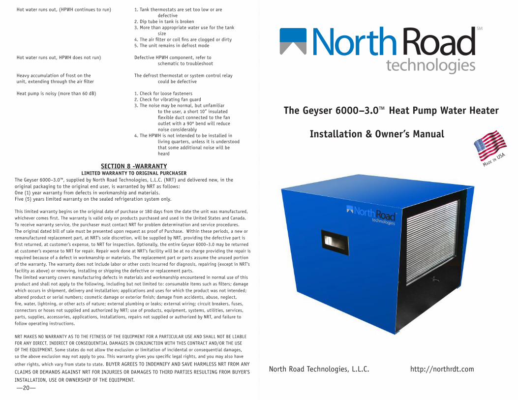
The Geyser 6000–3.0™ Heat Pump Water Heater
SM
Installation & Owner’s Manual
North Road Technologies, L.L.C. http://northrdt.com
Made in USa
—20—
The Geyser 6000–3.0™ must NOT be connected to an electric water heater with heating elements larger than 240 volt/5500 watts.
SECTION 7—TROUBLE SHOOTING GUIDE
Problem Possible Cause and Solution No hot water flow at tap. Valve on old water pipe supplying water tank should be open, faucet aerator or restrictor may be plugged with sediment.
High Pressure Limit switch 1. Repeat system purge operation opens repeatedly 2. Unit plumbed incorrectly, cold water on bottom of feed tank connected to HPWH outlet 3. Defective circulating pump 4. Tank thermostat set too high 5. Defective tank thermostat 6. Inadequate water flow due to plugged water lines
Water on floor around the tank 1. Check plumbing joints and fittings for leaks 2. Make sue HPWH is level 3. Check condensate drain line for obstruction 4. Inspect drip pan for obstruction 5. If leak continues after unit is turned off, there is an internal leak requiring service 6. The leak may be from the water storage tank
Heat pump trips a house 1. Circuit does not have adequate circuit breaker capacity circuit breaker 2. There is a short, or loose connection in field wiring 3. There is a short or loose connection in HPWH wiring 4. Check to be sure that dual resistance elements are not wired for simultaneous operation. Total wattage must not exceed 5500 watts
Water is not being heated 1. Check tank top thermostat. A setting of 125º F. at the thermostat should sufficiently allow for 120º F. at the tap 2. A mixing/tempering valve in the house plumbing could be mixing cold water with the hot. Close the HPWH cold water inlet valve, and open a hot water faucet in the house. No water should come out of the faucet. If it does, cold water is coming from the mixing valve
Water is too hot 1. Check the tank top thermostat and limit switch 2. Check the tank lower thermostat and limit switch 3. Check the HPWH for proper response to the thermostat
Water is not being heated 1. Check to make sure unit is plugged in, turned on, at all and the circuit breaker/fuse is not tripped 2. Check the tank top heating element, limit switch, and thermostat
—19— —2—
SAFETY INFORMATION(PLEASE READ AND FOLLOW THIS SECTION CAREFULLY TO PREVENT ACCIDENTS OR INJURIES)
The GEYSER 6000–3.0™ Heat Pump Water Heater must be installed in accordance with local and national codes and the instructions in this manual. Before beginning the
installation, read the entire manual and check the local, state, and national building, electrical, and plumbing codes or authorities. Failure to install according to these
instructions and codes may result in property damage, bodily injury, or death.
An air discharge fan is located on the unit. Extreme caution must be exercised to ensure that any foreign objects do not enter the fan area. Do not stand or sit on unit. Do not allow children to play on or near the unit. Disconnect all power before removing cover (note that there is no need to remove the cover except to adjust the temperature settings). Internal components may be hot to the touch. Please allow unit to cool completely before touching any component. Disconnect power before installing or servicing the GEYSER 6000–3.0™. Ensure that the power receptacle is rated for 115 V. and at least 15 A. Ensure that the electrical supply has proper overload fuse or breaker protection rated for at least 15 amps. It is suggested to use a dedicated outlet. Wear eye protection during the installation. The GEYSER 6000–3.0™ system weighs approximately 70 lbs. All lifting should be done using the handles on the side of the unit with caution and assistance if available to prevent injury. If the pressure relief valve on the existing water heater tank is leaking or dripping, call a licensed plumber for repair. Do not plug or remove valve as this could result in an explosion. Water temperature over 125ºF. (52º C.) can cause severe burns instantly resulting in severe injury or death. The GEYSER 6000–3.0™ is shipped at the default setting of 120°F. in accordance with Department of Energy standards. Follow all safety instructions provided by the manufacturer of the existing water heater. The Geyser 6000–3.0™ must NOT be installed in location where it is exposed to temperatures of below 40°F. (4.5°C.) or above 120°F. (49°C.).
SAFETY INFORMATION Examine your water tank; make sure it is not rusty or leaking. Depending on the condition and age of the tank, this may be the best time for replacement. Before
installing the GEYSER 6000–3.0™, make sure that the water heater is on a flat surface and properly secured.
SECTION 6–HEAT PUMP WATER HEATER MAINTENANCE WARNING
BEFORE SERVICING THE EXISTING GEYSER, OR THE ELECTRIC WATER HEATER, UNPLUG THE UNIT(S), TURN OFF CIRCUIT BREAKER OR REMOVE THE FUSES
SUPPLYING POWER TO THE WATER HEATER. FAILURE TO DO SO MAY RESULT IN PROPERTY DAMAGE, BODILY INJURY, OR DEATH.
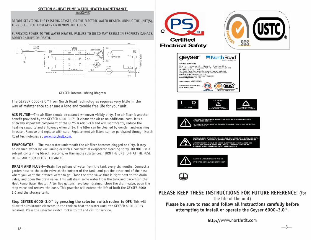
GEYSER Internal Wiring Diagram
The GEYSER 6000–3.0™ from North Road Technologies requires very little in the way of maintenance to ensure a long and trouble free life for your unit.
AIR FILTER—The air filter should be cleaned whenever visibly dirty. The air filter is another benefit provided by the GEYSER 6000–3.0™. It cleans the air at no additional cost. It is a critically important component of the GEYSER 6000–3.0 and will significantly reduce the heating capacity and efficiency when dirty. The filter can be cleaned by gently hand-washing in water. Remove and replace with care. Replacement air filters can be purchased through North Road Technologies at www.northrdt.com.
EVAPORATOR —The evaporator underneath the air filter becomes clogged or dirty, it may be cleaned either by vacuuming or with a commercial evaporator cleaning spray. DO NOT use a solvent containing bleach, acetone, or flammable substances. TURN THE UNIT OFF AT THE FUSE OR BREAKER BOX BEFORE CLEANING.
DRAIN AND FLUSH—Drain five gallons of water from the tank every six months. Connect a garden hose to the drain valve at the bottom of the tank, and put the other end of the hose where you want the drained water to go. Close the stop valve that is right next to the drain valve, and open the drain valve. This will drain some water from the tank and back-flush the Heat Pump Water Heater. After five gallons have been drained, close the drain valve, open the stop valve and remove the hose. This practice will extend the life of both the GEYSER 6000–3.0 and the storage tank.
Stop GEYSER 6000–3.0™ by pressing the selector switch rocker to OFF. This will allow the resistance elements in the tank to heat the water until the GEYSER 6000–3.0 is repaired. Press the selector switch rocker to off and call for service.
—3——18—
PLEASE KEEP THESE INSTRUCTIONS FOR FUTURE REFERENCE! (for the life of the unit)
Please be sure to read and follow all instructions carefully before attempting to install or operate the Geyser 6000–3.0™.
http://www.northrdt.com
Contents
SAFETY INFORMATION-------------------------------------------------------------------------2 Please Keep These Instructions For Reference -----------------------------------------3 GEYSER 6000–3.0™--------------------------------------------------------------------------5 Technical Specifications -------------------------------------------------------------------5 Features: -------------------------------------------------------------------------------------5 Unit Specifications: -------------------------------------------------------------------------5 Grounding instructions-----------------------------------------------------------------------6SYSTEM REQUIREMENTS -------------------------------------------------------------------6 INSTALLATION--------------------------------------------------------------------------------6 SECTION 1–General----------------------------------------------------------------------------6 SECTION 2–Location---------------------------------------------------------------------------8 SECTION 3–Plumbing ------------------------------------------------------------------------8SECTION 4–Electrical-------------------------------------------------------------------------13 SECTION 5–Operation------------------------------------------------------------------------16 SECTION 6–Heat Pump Water Heater Maintenance---------------------------------------18 SECTION 7–Trouble Shooting----------------------------------------------------------------19SECTION 8–Warranty-------------------------------------------------------------------------20
The GEYSER 6000–3.0™ will remove moisture from the air. It is an effective dehumidifier, and, depending on run time, may provide all necessary dehumidification. However, it will only dehumidify while it is running. As more hot water is used, more dehumidification is provided. The moisture may occasionally cause frost to form on the evaporator. When the frost builds up, the GEYSER 6000–3.0 will go into a defrost cycle. This could occur every two hours of operation in a cold, humid environment. While in a defrost mode period of 6 minutes, the fan will continue to run and the tank lower heating element will provide heat. When the defrost period is completed, the GEYSER 6000–3.0™ will resume heating water. Temperature Setting: The default setting for the thermostat/temperature setting is 120°F. (49°C.), in accordance with the U.S. Department of Energy Guidelines. Please note that the GEYSER 6000–3.0™ will heat the water up to 140°F. (60°C.), and this setting can be changed internally. The lever to adjust the temperature setting is located inside the electric box within the Geyser. To access it, first disconnect the power at the fuse or breaker box. Then, remove the rubber mounts on the bottom of the GEYSER and gently pull the sides away at the bottom and lift the cover off. The electric box is in the top of the unit, and within the electric box is an electronic circuit board. At one end of the board is a slide thermostat with temperature markings. Move the slide to the desired position you want to maintain in the tank, and replace the cover to the unit.
Check illuminated lights on Geyser unit Green solid LED—unit is on standby (Geyser is on, but not called to heat water). Green flashing LED—unit is on and calling for heat (compressor working/heat to tank).
Red LED flashes once every two seconds—unit is in defrost mode. Red LED flashes once every half second—the unit is in over current mode:. Note: unplug the unit and ensure all wiring is connected properly. If yes, then call for service. Red LED flashes 3 times—the thermistor is disconnected/broken for water temperature detection: If this condition persists, call for service. Red LED flashes 4 times—thermistor is disconnected/broken for defrost temperature detection. If this condition persists, call for service.
—4— —17—
SECTION 5 -OPERATION General Cycle
Most electric water tanks utilize two heating elements, one at the top of the tank and one at the bottom of the tank. The heating element at the top of the tank is called a “quick recovery” element, because it is designed to heat water at the top of the tank if the temperature at the top of the tank falls below its set point. The heating element at the bottom of the tank actually provides most of the heating of the water. With an electric water heater, after the water in the top third of the tank is hot, the lower heating element will heat the water in the bottom two thirds of the tank. The cold water that enters the tank to replace the hot water being used enters at the bottom so that it will not cool the hot water near the top exit. Hot water rises to the top of the tank, and cold water falls to the bottom. The bottom thermostat brings the lower element on after a few gallons of hot water are used.
The GEYSER 6000–3.0 replaces the lower element in operation. Instead of the lower element providing most of the hot water, the GEYSER 6000–3.0 provides it. When the GEYSER 6000–3.0™ thermostat calls for heat, the electrical circuit is closed and the air fan, water circulating pump, and compressor in the GEYSER 6000–3.0 start. The compressor causes a differential pressure between the evaporator and the condenser. In the evaporator, the refrigerant evaporates and cools, drawing heat from the air being forced through its fins. In the condenser, refrigerant vapor is condensed, giving off heat to the water being circulated from the storage tank.
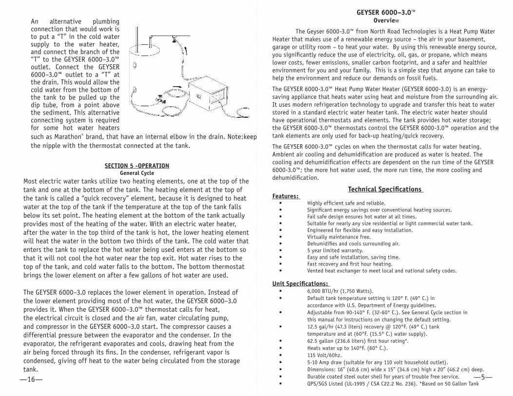
An alternative plumbing connection that would work is to put a “T” in the cold water supply to the water heater, and connect the branch of the “T” to the GEYSER 6000–3.0™ outlet. Connect the GEYSER 6000–3.0™ outlet to a “T” at the drain. This would allow the cold water from the bottom of the tank to be pulled up the dip tube, from a point above the sediment. This alternative connecting system is required for some hot water heaters such as Marathon® brand, that have an internal elbow in the drain. Note:keep the nipple with the thermostat connected at the tank.
GEYSER 6000–3.0™ Overview
The Geyser 6000-3.0™ from North Road Technologies is a Heat Pump Water Heater that makes use of a renewable energy source – the air in your basement, garage or utility room – to heat your water. By using this renewable energy source, you significantly reduce the use of electricity, oil, gas, or propane, which means lower costs, fewer emissions, smaller carbon footprint, and a safer and healthier environment for you and your family. This is a simple step that anyone can take to help the environment and reduce our demands on fossil fuels.
The GEYSER 6000-3.0™ Heat Pump Water Heater (GEYSER 6000-3.0) is an energy-saving appliance that heats water using heat and moisture from the surrounding air. It uses modern refrigeration technology to upgrade and transfer this heat to water stored in a standard electric water heater tank. The electric water heater should have operational thermostats and elements. The tank provides hot water storage; the GEYSER 6000-3.0™ thermostats control the GEYSER 6000-3.0™ operation and the tank elements are only used for back-up heating/quick recovery.
The GEYSER 6000-3.0™ cycles on when the thermostat calls for water heating. Ambient air cooling and dehumidification are produced as water is heated. The cooling and dehumidification effects are dependent on the run time of the GEYSER 6000-3.0™; the more hot water used, the more run time, the more cooling and dehumidification.
Technical Specifications Features:
Highly efficient safe and reliable. Significant energy savings over conventional heating sources. Fail safe design ensures hot water at all times. Suitable for nearly any size residential or light commercial water tank. Engineered for flexible and easy installation. Virtually maintenance free. Dehumidifies and cools surrounding air. 5 year limited warranty. Easy and safe installation, saving time. Fast recovery and first hour heating. Vented heat exchanger to meet local and national safety codes.
Unit Specifications: 6,000 BTU/hr (1,750 Watts). Default tank temperature setting is 120° F. (49° C.) in accordance with U.S. Department of Energy guidelines.Adjustable from 90-140° F. (32-60° C.). See General Cycle section in this manual for instructions on changing the default setting. 12.5 gal/hr (47.3 liters) recovery @ 120°F. (49° C.) tank temperature and at (60°F. (15.5° C.) water supply). 62.5 gallon (236.6 liters) first hour rating*. Heats water up to 140°F. (60° C.). 115 Volt/60hz. 5-10 Amp draw (suitable for any 110 volt household outlet). Dimensions: 16” (40.6 cm) wide x 15” (34.6 cm) high x 20” (46.2 cm) deep. Durable coated steel outer shell for years of trouble free service. QPS/SGS Listed (UL-1995 / CSA C22.2 No. 236). *Based on 50 Gallon Tank
•••••••••••
••
•
•
•••••••
—5——16—
SYSTEM REQUIREMENTS
The GEYSER 6000–3.0™ can only be placed in dry/covered location, in areas where the temp will not fall below 40°F. (4.5°C.). If using the unit in an attic, garage or basement, the unit can be installed without any additional equipment. However, if your water heater is in a space with less than 1,500 cubic feet (42.5 cubic meters), consider ordering longer hoses to locate GEYSER 6000–3.0™ in a suitable location.
The GEYSER 6000–3.0™ connects to a typical household outlet, 115 volt, 15 amp. While the device requires about 12 Amps momentarily upon power-up, the device draws 5-8 Amps on average during operation. It is recommended that a dedicated 15 amp circuit be used to power the GEYSER 6000-3.0™.
The GEYSER 6000-3.0™ is recommended for tanks 30 gallons (115 Liters) and larger. A drain must be available to accommodate condensate generated by the GEYSER 6000–3.0™. In high humidity environments, this condensation can amount to as much as 50 pints (24 Liters) per day. The condensate can be routed to a floor drain, a sink, expelled into a plumbing vent pipe or house waste line, or to the outside or by way of a drain hose included with the GEYSER 6000–3.0™. The drain line discharges via gravity, so it is important to locate the drain line appropriately.
INSTALLATION
SECTION 1—GENERALTools required for the installation:
Phillips head screw driver Flat head screw driver Pipe wrench 3/4” Hole saw Safety gloves Safety glasses Electrical Tape
Grounding instructions This heat pump water heater is for use on 115 volts. The cord has a plug as shown at A in Figure below. An adapter as shown at C is available for connecting three-blade grounding-type plugs to two-slot receptacles. The green grounding lug extending from the adapter must be connected to a permanent ground such as a properly grounded outlet box. The adapter should not be used if a three-slot grounded receptacle is available.
The Geyser heat pump water heater is for use at 115 volts. The cord has a plug as shown at A on the figure on the next page. An adaptor, as shown at C, is available for connecting a three–blade grounding–type plug to two–slot recepticles. The green grounding lug extending from the adaptor must be connected to a permanent ground, such as a properly grounded outlet box. The adaptor should not be used if a three–slot grounded receptacle is available.
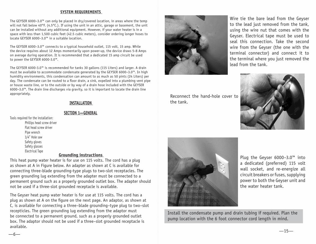
Wire tie the bare lead from the Geyser to the lead just removed from the tank, using the wire nut that comes with the Geyser. Electrical tape must be used to seal this connection. Take the second wire from the Geyser (the one with the terminal connector) and connect it to the terminal where you just removed the lead from the tank.
Reconnect the hand-hole cover to the tank.
Plug the Geyser 6000–3.0™ into a dedicated (preferred) 115 volt wall socket, and re-energize all circuit breakers or fuses, supplying power to both the Geyser unit and the water heater tank.
Install the condensate pump and drain tubing if required. Plan the pump location with the 6 foot connector cord length in mind.
—6— —15—
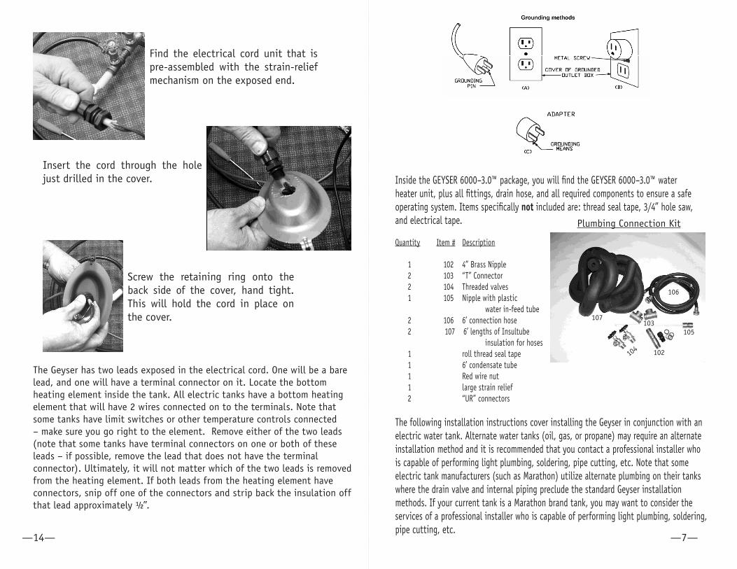
Find the electrical cord unit that is pre-assembled with the strain-relief mechanism on the exposed end.
Insert the cord through the hole just drilled in the cover.
Screw the retaining ring onto the back side of the cover, hand tight. This will hold the cord in place on the cover.
The Geyser has two leads exposed in the electrical cord. One will be a bare lead, and one will have a terminal connector on it. Locate the bottom heating element inside the tank. All electric tanks have a bottom heating element that will have 2 wires connected on to the terminals. Note that some tanks have limit switches or other temperature controls connected – make sure you go right to the element. Remove either of the two leads (note that some tanks have terminal connectors on one or both of these leads – if possible, remove the lead that does not have the terminal connector). Ultimately, it will not matter which of the two leads is removed from the heating element. If both leads from the heating element have connectors, snip off one of the connectors and strip back the insulation off that lead approximately ½”.
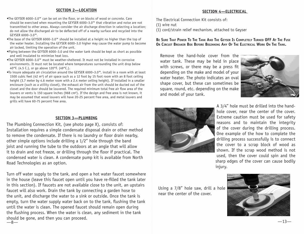
Inside the GEYSER 6000–3.0™ package, you will find the GEYSER 6000–3.0™ water heater unit, plus all fittings, drain hose, and all required components to ensure a safe operating system. Items specifically not included are: thread seal tape, 3/4” hole saw, and electrical tape.
Quantity Item # Description
1 102 4” Brass Nipple 2 103 “T” Connector 2 104 Threaded valves 1 105 Nipple with plastic water in-feed tube 2 106 6’ connection hose 2 107 6’ lengths of Insultube insulation for hoses 1 roll thread seal tape 1 6’ condensate tube 1 Red wire nut 1 large strain relief 2 “UR” connectors The following installation instructions cover installing the Geyser in conjunction with an electric water tank. Alternate water tanks (oil, gas, or propane) may require an alternate installation method and it is recommended that you contact a professional installer who is capable of performing light plumbing, soldering, pipe cutting, etc. Note that some electric tank manufacturers (such as Marathon) utilize alternate plumbing on their tanks where the drain valve and internal piping preclude the standard Geyser installation methods. If your current tank is a Marathon brand tank, you may want to consider the services of a professional installer who is capable of performing light plumbing, soldering, pipe cutting, etc.
102
103
104
106
107
105
Plumbing Connection Kit
—14— —7—
SECTION 2—LOCATION
•The GEYSER 6000–3.0™ can be set on the floor, or on blocks of wood or concrete. Care should be exercised when mounting the GEYSER 6000–3.0™ that vibration and noise are not transmitted to other areas. Always consider the air discharge direction in selecting a location; do not allow the discharged air to be deflected off of a nearby surface and recycled into the GEYSER 6000–3.0™.
•The base of the GEYSER 6000–3.0™ should be installed at a height no higher than the top of the water heater. Installing the GEYSER 6000–3.0 higher may cause the water pump to become air locked, limiting the operation of the unit.
•Piping between the GEYSER 6000–3.0 and the water tank should be kept as short as possible and well insulated to minimize heat loss.
•The GEYSER 6000–3.0™ must be weather-sheltered. It must not be installed in corrosive environments. It must not be located where temperatures surrounding the unit drop below 40°F. (4.5 C.), or go above 120°F. (49°C.).
•To insure adequate air circulation around the GEYSER 6000–3.0™, install in a room with at least 1500 cubic feet (42 m³) of air space such as a 12 foot by 15 foot room with an 8 foot ceiling height (3.7 meter by 4.6 meter room with a 2.4 meter ceiling height). If installed in a smaller enclosure (such as a utility closet), the exhaust air from the unit should be ducted out of the closet and the door should be louvered. The required minimum total free air flow area of the louvers or vents is 150 square inches (968 cm²). If the design and free area is not known, it may be assumed that wood louvers will have 20-25 percent free area, and metal louvers and grills will have 60-75 percent free area.
SECTION 3—PLUMBING
The Plumbing Connection Kit, (see photo page X), consists of: Installation requires a simple condensate disposal drain or other method to remove the condensate. If there is no laundry or floor drain nearby, other simple options include drilling a 1/2” hole through the band joist and running the tube to the outdoors at an angle that will allow it to drain and not freeze, or drilling through the floor if practical. The condensed water is clean. A condensate pump kit is available from North Road Technologies as an option.
Turn off water supply to the tank, and open a hot water faucet somewhere in the house (leave this faucet open until you have re-filled the tank later in this section). If faucets are not available close to the unit, an upstairs faucet will also work. Drain the tank by connecting a garden hose to the unit, and discharge the water to a sink or outside. Once the tank is empty, turn the water supply water back on to the tank, flushing the tank until the water is clean. The opened faucet should remain open during the flushing process. When the water is clean, any sediment in the tank should be gone, and then you can proceed.
A 3/4” hole must be drilled into the hand-hole cover, near the center of the cover. Extreme caution must be used for safety reasons and to maintain the integrity of the cover during the drilling process. One example of the how to complete the drilling process successfully is to connect the cover to a scrap block of wood as shown. If the scrap wood method is not used, then the cover could spin and the sharp edges of the cover can cause bodily injury.
Using a 7/8” hole saw, drill a hole near the center of the cover.
Remove the hand-hole cover from the water tank. These may be held in place with screws, or there may be a press fit depending on the make and model of your water heater. The photo indicates an oval shape cover, but these can sometimes be square, round, etc. depending on the make and model of your tank.
SECTION 4—ELECTRICAL
The Electrical Connection Kit consists of: (1) wire nut (1) cord/strain relief mechanism, attached to Geyser
Be Sure ThaT Power To The Tank and The GeySer IS ComPleTely Turned oFF aT The FuSe or CIrCuIT Breaker Box BeFore BeGInnInG any oF The eleCTrICal work on The Tank.
—8— —13—
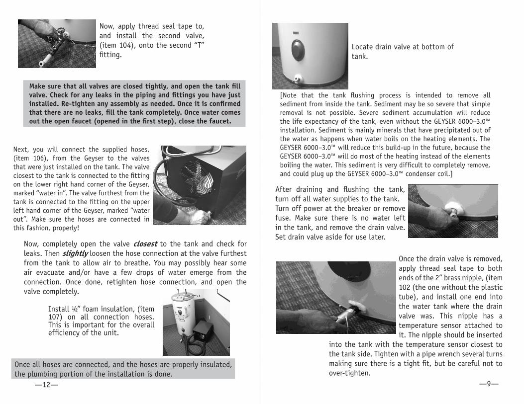
Once the drain valve is removed, apply thread seal tape to both ends of the 2” brass nipple, (item 102 (the one without the plastic tube), and install one end into the water tank where the drain valve was. This nipple has a temperature sensor attached to it. The nipple should be inserted
into the tank with the temperature sensor closest to the tank side. Tighten with a pipe wrench several turns making sure there is a tight fit, but be careful not to over-tighten.
Next, you will connect the supplied hoses, (item 106), from the Geyser to the valves that were just installed on the tank. The valve closest to the tank is connected to the fitting on the lower right hand corner of the Geyser, marked “water in”. The valve furthest from the tank is connected to the fitting on the upper left hand corner of the Geyser, marked “water out”. Make sure the hoses are connected in this fashion, properly!
Install ½” foam insulation, (item 107) on all connection hoses. This is important for the overall efficiency of the unit.
Once all hoses are connected, and the hoses are properly insulated, the plumbing portion of the installation is done.
Now, completely open the valve closest to the tank and check for leaks. Then slightly loosen the hose connection at the valve furthest from the tank to allow air to breathe. You may possibly hear some air evacuate and/or have a few drops of water emerge from the connection. Once done, retighten hose connection, and open the valve completely.
Locate drain valve at bottom of tank.
After draining and flushing the tank, turn off all water supplies to the tank.Turn off power at the breaker or remove fuse. Make sure there is no water left in the tank, and remove the drain valve. Set drain valve aside for use later.
—12—
Make sure that all valves are closed tightly, and open the tank fill valve. Check for any leaks in the piping and fittings you have just installed. Re-tighten any assembly as needed. Once it is confirmed that there are no leaks, fill the tank completely. Once water comes out the open faucet (opened in the first step), close the faucet.
[Note that the tank flushing process is intended to remove all sediment from inside the tank. Sediment may be so severe that simple removal is not possible. Severe sediment accumulation will reduce the life expectancy of the tank, even without the GEYSER 6000–3.0™ installation. Sediment is mainly minerals that have precipitated out of the water as happens when water boils on the heating elements. The GEYSER 6000–3.0™ will reduce this build-up in the future, because the GEYSER 6000–3.0™ will do most of the heating instead of the elements boiling the water. This sediment is very difficult to completely remove, and could plug up the GEYSER 6000–3.0™ condenser coil.]
—9—
Now, apply thread seal tape to, and install the second valve, (item 104), onto the second “T” fitting.
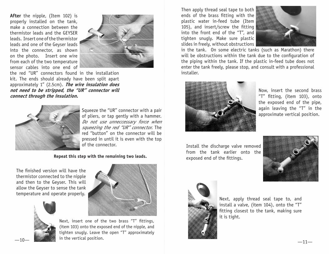
Then apply thread seal tape to both ends of the brass fitting with the plastic water in-feed tube (Item 105), and insert/screw the fitting into the front end of the ‘‘T”, and tighten snugly. Make sure plastic slides in freely, without obstructions in the tank. On some electric tanks (such as Marathon) there will be obstructions within the tank due to the configuration of the piping within the tank. If the plastic in-feed tube does not enter the tank freely, please stop, and consult with a professional installer.
Now, insert the second brass “T” fitting, (item 103), onto the exposed end of the pipe, again leaving the “T” in the approximate vertical position.
Install the discharge valve removed from the tank earlier onto the exposed end of the fittings.
Next, apply thread seal tape to, and install a valve, (item 104), onto the “T” fitting closest to the tank, making sure it is tight.
—10— —11—
After the nipple, (Item 102) is properly installed on the tank, make a connection between the thermistor leads and the GEYSER leads. Insert one of the thermistor leads and one of the Geyser leads into the connector, as shown on the photo. Insert one wire from each of the two temperature sensor cables into one end of the red “UR” connectors found in the installation kit. The ends should already have been split apart approximately 1” (2.5cm). The wire insulation does not need to be stripped, the “UR” connector will connect through the insulation.
Squeeze the “UR” connector with a pair of pliers, or tap gently with a hammer. Do not use unneccessary force when squeezing the red “UR” connector. The red “button” on the connector will be pressed in until it is even with the top of the connector.
Repeat this step with the remaining two leads.
The finished version will have the thermistor connected to the nipple and then to the Geyser. This will allow the Geyser to sense the tank temperature and operate properly.
Next, insert one of the two brass “T” fittings, (item 103) onto the exposed end of the nipple, and tighten snugly. Leave the open “T” approximately in the vertical position.