the grain shape dependence of springback of integrated circuit leadframes
TRANSCRIPT
Materials Science and Engineering A270 (1999) 323–329
The grain shape dependence of springback of integrated circuitleadframes
K.C. Chan *, S.H. WangDepartment of Manufacturing Engineering, The Hong Kong Polytechnic Uni6ersity, Hung Hom, Kowloon, Hong Kong, Peoples’
Republic of China
Received 25 February 1999; received in revised form 24 May 1999
Abstract
Anisotropy is known to be an important factor in affecting springback and deformation behaviour of cold rolled integratedcircuit (IC) leadframes. Less work has been carried out to study the effect of grain shape on springback of IC leadframes, thoughit is considered to be a source of plastic anisotropy. In this paper, a plane stress model based on the concept of relaxed constraintshas been developed to investigate the effect of grain shape on springback of a cold rolled copper alloy. Comparisons between thepredictions by the relaxed constraint model and the conventional full constraints model and the experimental results have beenmade. It is found that significant improvement has been obtained by using the new model. © 1999 Elsevier Science S.A. All rightsreserved.
Keywords: Anisotropy; Springback; Copper alloy
www.elsevier.com/locate/msea
1. Introduction
Springback is shown to be one of major concerns informing of integrated circuit (IC) leadframes [1]. Re-cently, one of the authors and his co-workers haveperformed a series of experiments to investigate therelationships between the springback and the propertiesof material and geometry of the forming tools [1]. It isfound that both the material properties and the geome-try of forming tools are related to springback of ICleadframes. The experimental results further reveal thatspringback of the leadframes deformed along therolling direction is larger than that perpendicular to therolling direction. The authors have proposed a newplane stress bending model [2] based on the approachof Crystallographic Mechanics of Textured Polycrystals(CMTP) to explain the deformation behaviour [3]. Intheir model, preferred orientations are assumed to bethe only source for the plastic anisotropy. Based on thetexture data obtained from the measured orientationdistribution function and the assumption of full con-
straints deformation, the general trend of the predic-tions is consistent with the experimental findings.However, Kocks [4] and Fleischer [5] have argued thatthe assumption of full constraints is too severe and isnot necessary for cold rolled metal sheets. The modifi-cation of the Taylor model was first suggested byHonneff and Mecking [6] and later developed byKocks, Jonas, Canova, and others [7–9]. It is assumedthat for metal sheets with elongated grains, there is apartial relaxation of the Taylor requirement for equalstrains throughout a material. This method has beensuccessfully applied to predict the yield surface and thedevelopment of texture [8,10], but less has been adoptedin the study of springback problem. In this paper, aplane stress model taking into consideration of bothcrystallographic texture and grain shape will be furtherproposed to predict the deformation behavior andspringback of IC leadframes.
2. Modeling
In the theoretical model, a narrow metal strip sub-jected to the bending deformation is considered. Duringthe bending process, we assume that the cross-section
* Corresponding author. Tel.: +852-27664981; fax: +852-23625267.
E-mail address: [email protected] (K.C. Chan)
0921-5093/99/$ - see front matter © 1999 Elsevier Science S.A. All rights reserved.
PII: S0921 -5093 (99 )00256 -7

K.C. Chan, S.H. Wang / Materials Science and Engineering A270 (1999) 323–329324
of the narrow metal strip is normal to the bending axis.The stress state is assumed to be plane stress state. Fig.1 illustrates the geometry of a bent narrow strip. Thenarrow strip of IC leadframe is usually manufacturedthrough photo-etching from a thin metal sheet, whichhas been heavily rolled before using. Its grains areheavily distorted from its initially nearly equi-axedstate. Considering a typical rolling grain of ‘chocolatebar shape’, as shown in Fig. 2, when the strip is bentunder plane stress state, it is considered that the incre-mental shear strain dout and doru have to be zero, i.e.dotu=doru=0. Otherwise, the u− t plane and the u−rplane will be no longer perpendicular to the bendingaxis, which is in conflict with the assumption of purebending. However, the incremental shear strain dort canbe of values other than zero, without violating theassumption. Fig. 2a shows the shear strains of the grainin a narrow metal strip subjected to bending along therolling direction, while Fig. 2b illustrates a strip beingbent perpendicular to the rolling direction. In bothcases, the shear strains dotu and doru are prescribed andequal to zero, while the shear strain dort is free to varyfor different grains.
The strain tensor referred to the specimen axes cantherefore be expressed as:
o(s)=do(s)ÃÆ
È
100
0xyz
0yz
−1−xÃÇ
É(1)
where x and yz are dimensionless parameters and do(s) isthe strain increment. It should be noted that the shearstrain component yz is allowed to vary from grain tograin. In the model, the leadframe strip is assumed tobe divided into n layers. For each layer having infinites-imal dimensions in the radial and circumferential direc-tion but with the full width in the transverse direction,the force equilibrium equation can be expressed by:
(sr(s)+dsr(s))(w+dw)(r+dr)du−sr(s)wrdu
−2su(s)dr(w+dw)sindu
2=0 (2)
Fig. 2. (a) Grain shape and shear strain for bending along the rollingdirection. (b) Grain shape and shear strain for bending perpendicularto the rolling direction.
where du is an infinitesimal angle between two radialplanes which bound the element. The strip is alsoconsidered to consist of G groups of grains each withvolume fraction fg (g=1, G) and orientation {hkl}Bu6w\ . Since the CMTP yield criterion is referred tothe B100\ axis of the grain, the strain tensor o(s)(g)
has to be transformed to the cube axis of the grain bythe following relationship:
o(c)(g)=Po(s)(g)PT (3)
where P is the transformation matrix and PT is thetranspose of P with:
P=ÃÆ
È
r1
r2
r3
j1
j2
j3
k1
k2
k3
ÃÇ
É
j1=u/u2+62+w2, k1=h/h2+k2+ l2
j2=6/u2+62+w2, k2=k/h2+k2+ l2
j3=w/u2+62+w2, k3= l/h2+k2+ l2
and r= j×k.The CMTP yield criterion adopted in this paper is
given by [3]:
F(S(c)(g))
=a [�S11−S22�n+ �S22−S33�n+ �S33−S11�n]+2b [�S23�n+ �S31�n+ �S12�n]= (6tc)n (4)
where a, b and n are parameters that depend on theGaussian distribution of the scatter width of the grainorientation [3], and the stress tensor S(c)(g) is referred tothe B100\ axes of the ideal orientation. The stresstensor S(c) is related to the strain tensor o(c)(g) by apply-ing the normality rule to the analytical yield function ofEq. (4) as follows:
o(c)(g)=l(F(S(c)(g))(S(c)(g)
. (5)Fig. 1. Geometry of a bent narrow strip.

K.C. Chan, S.H. Wang / Materials Science and Engineering A270 (1999) 323–329 325
For simplicity, an isotropic hardening of the slip sys-tems of the following form is employed:
tc=K(G)N (6)
where N is the hardening exponent of the slip planes,and G the amount of shear strain per grain which isgiven by:
G(do(c)(g))=&
Mdo(c)(g) (7)
where M is the Taylor factor.In the calculation, the stress and strain tensors can be
simplified to ones, which contain only five independentcomponent [3] of the form:
ok(c)(g)= [(o22(c)(g)−o11(c)(g))/21/2, (3/2)1/2
o33(c)(g), 21/2o23(c)(g), 21/2o31(c)(g), 21/2o12(c)(g)] (8)
where k=1, 5. And the yield function can be rewrittenwith the five independent stress tensor as:
F(S(c)(g))
=a2−n/2[�2S1�n+ �S1−31/2S2�n+ �S1+31/2S2�n]+b21−n/2[�S3�n+ �S4�n+ �S5�n]= (6tc)n. (9)
By using the Newton–Raphson iteration method, thestress components for each grain can be obtained,which can then be transformed into the specimen axes:
S(s)(g)=PTS(c)(g)P. (10)
The stress acting on the layer S(s)(p) can then be ob-tained by summing up the stresses Sij(s)(g) for all thegrains:
S(s)(p)= %G
g=1
fgS(s)(g). (11)
By varying the parameters x and yz in Eq. (1), until thestress tensor S(s)(p) of the calculated layer of the stripsatisfies the plane stress condition and the force equi-librium condition as represented by Eq. (2), the stressS(s)(p) for a layer can be determined. It is worth tomention that the Hooke–Jeeves optimization method[11] is employed to reduce the long computation time.
For a specific bending radius and angle, when thestresses for all layers are determined, the bending mo-ment per unit length can be obtained by integrating thecircumferential stress su across the thickness and thewidth direction with respect to the current center ofcurvature:
MB=&
suwrdr. (12)
By assuming that the Young’s modulus of the stripalong and perpendicular to the rolling direction areEalong and Eperp. respectively and that the springback is
resulted from fully elastic recovery, the curvatures ofunstretched fiber before and after unload are related bythe following expressions:
1r %u(along)
=1
ru(along)
−MB
EalongI(along rolling direction)
(13a)
1r %u(perp.)
=1
ru(perp.)
−MB
Eperp.I(perpendicular to rolling direction).
(13b)
The unstretched fiber is taken as the springback axisso that the length of the fiber before and after spring-back is the same. Hence, the final angle after spring-back is expressed as:
u %along=ru(along)
r %u(along)
· u (14a)
u %perp.=ru(perp.)
r %u(perp.)
· u. (14b)
A computer program has been written to simulate thebending process. Fig. 3 illustrates the computationscheme of the model.
3. Results and discussion
The springback and deformation behaviour of a coldrolled copper alloy are investigated in the paper. Thenarrow metal leadframe strip is of 0.15 mm thicknessand 0.20 mm in width. The bending experiment isperformed by a special cantilever-type forming jig [1].In the bending process, the final bending angle is 90°and the die radii are of 1.0, 1.5, 2.0, 2.5 and 3.0 mm.The die gap is fixed to be zero in the experiment. Theanisotropic properties of the copper alloy, crystallo-graphic textures of the copper alloy are measured by aPhilips X-ray diffractometer. Three incomplete polefigures: (111), (200) and (220) are obtained by the backreflection method at 5° increments using Cu Ka radia-tion. From the pole figures, the orientation distributionfunction and the quantitative texture component arecalculated by the software developed by Cai and Leeusing the series expansion method [12]. The crystallo-graphic textures are presented by {110}B112\(67.13%)+{102}B 211\ (14.21%)+{010}B 001\(10.19%)+{323}B131\ (8.47%). The random or-ientations are not taken into account in the simulationfor simplifying the calculation. For zero scatter width,the parameters a, b, n in Eq. (4) or Eq. (9) are chosento be 1.6, 0.46 and 0.51, respectively [3]. The mic-roscopic work hardening exponent N for the

K.C. Chan, S.H. Wang / Materials Science and Engineering A270 (1999) 323–329326
copper alloy is assumed to be 0.59. In the simulation,the strip is divided into 15 layers and bent to 90° in onestep. The parameter x varies from −1.0 to 0.0, and theparameter yz varies from −1.0 to 1.0.
The anisotropic elastic properties of the material arealso related to the crystallographic texture. The effec-tive Young’s modulus, Ed, along any direction d in-dexed by Miller indices [hkl ], can be given by [13]:
1Ed
=s11+(2s12−2s11+s44)(k2l2+ l2h2+h2k2)
(h2+k2+ l2)2 (15)
where s11, s12 and s44 are the elastic compliance con-stants for the copper alloy. Using Eq. (15) and theabove texture data, the ratio of elastic modulus alongthe rolling direction and perpendicular to the rollingdirection is obtained. The elastic modulus of the metalstrip for bending along the rolling direction Ealong wasmeasured to be 125 Gpa, and the elastic modulus
Fig. 4. Relationship between strip thickness and die radius.
perpendicular to the rolling direction Eperp. can then becalculated.
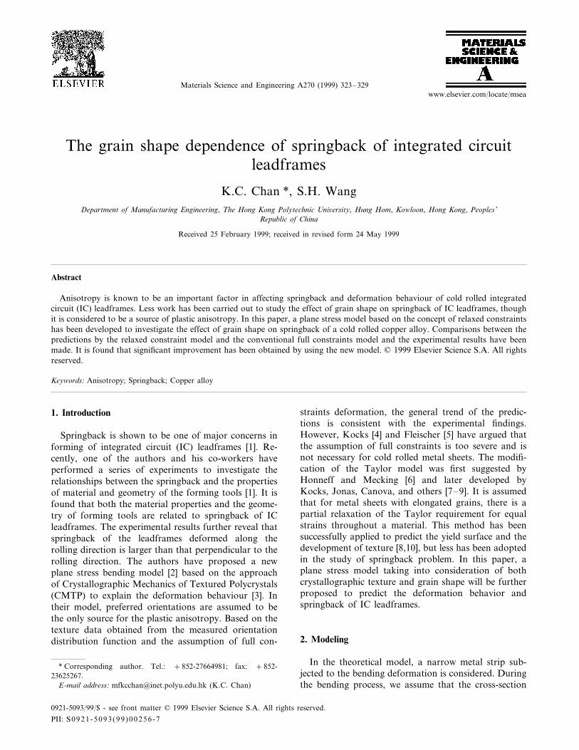
Fig. 4 illustrates the predicted relationship betweenthe strip thickness and the die radius. It is found thatthe strip thickness decreases with decreasing die radius,and for a specific die radius, the amount of reduction instrip thickness is greater when the bending is perpendic-ular to the rolling direction. The predicted relationshipbetween the width and the thickness of bent strips withdie radii of 1.5, 2.0 and 3.0 mm is also illustrated inFig. 5. The width changes significantly along the thick-ness direction. A minimal width is found at the outerlayer where it is subjected to a tensile stress, and amaximum variation in width is observed at a die radiusof 1.5 mm. Fig. 6 further reveals that the amount ofwidth change is greater for a strip bent along the rollingdirection. Since the variation of width change along thethickness direction leads to a distorted trapezoidal crosssection of the strip, a more distorted trapezoidal crosssection is expected for the strip deformed under asmaller die radius and along the rolling direction. It isworthwhile pointing out that anticlastic effect in the
Fig. 3. Computational scheme of the model.Fig. 5. Width change along the thickness direction for different dieradii.
K.C. Chan, S.H. Wang / Materials Science and Engineering A270 (1999) 323–329 327
Fig. 6. Comparison of width change between bending along therolling direction and bending perpendicular to the rolling direction.
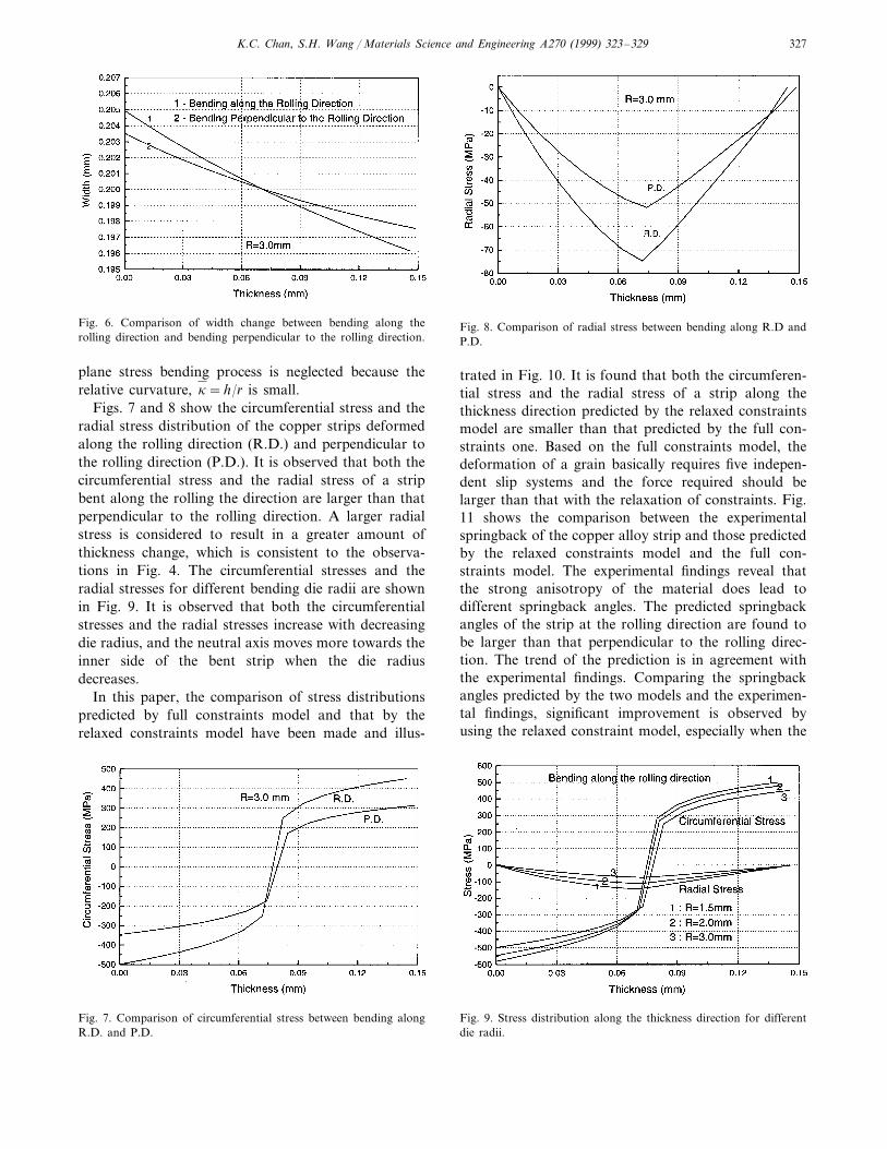
Fig. 8. Comparison of radial stress between bending along R.D andP.D.
plane stress bending process is neglected because therelative curvature, k=h/r is small.
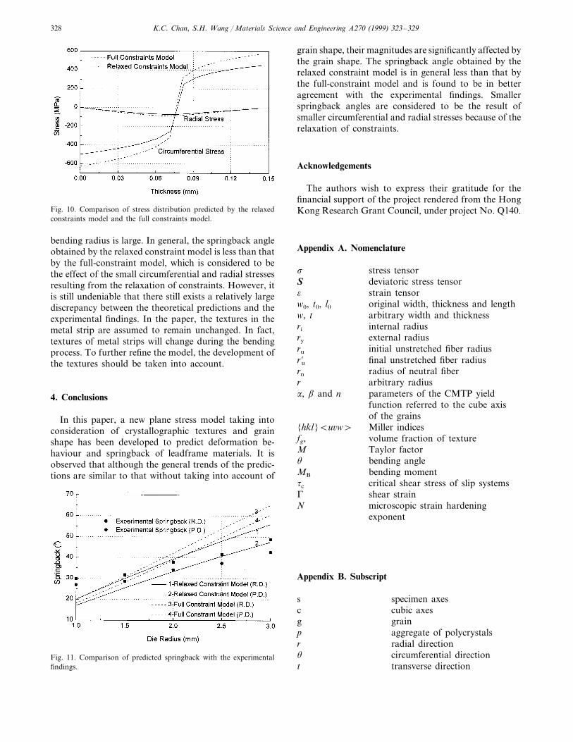
Figs. 7 and 8 show the circumferential stress and theradial stress distribution of the copper strips deformedalong the rolling direction (R.D.) and perpendicular tothe rolling direction (P.D.). It is observed that both thecircumferential stress and the radial stress of a stripbent along the rolling the direction are larger than thatperpendicular to the rolling direction. A larger radialstress is considered to result in a greater amount ofthickness change, which is consistent to the observa-tions in Fig. 4. The circumferential stresses and theradial stresses for different bending die radii are shownin Fig. 9. It is observed that both the circumferentialstresses and the radial stresses increase with decreasingdie radius, and the neutral axis moves more towards theinner side of the bent strip when the die radiusdecreases.
In this paper, the comparison of stress distributionspredicted by full constraints model and that by therelaxed constraints model have been made and illus-
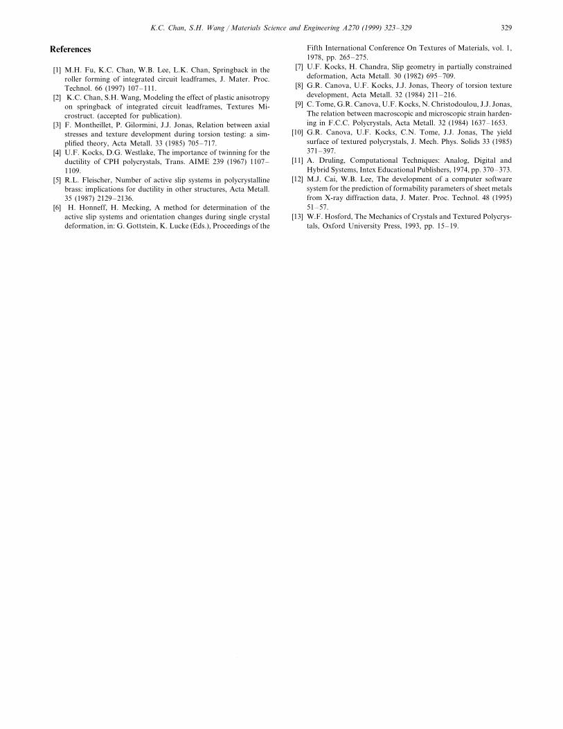
trated in Fig. 10. It is found that both the circumferen-tial stress and the radial stress of a strip along thethickness direction predicted by the relaxed constraintsmodel are smaller than that predicted by the full con-straints one. Based on the full constraints model, thedeformation of a grain basically requires five indepen-dent slip systems and the force required should belarger than that with the relaxation of constraints. Fig.11 shows the comparison between the experimentalspringback of the copper alloy strip and those predictedby the relaxed constraints model and the full con-straints model. The experimental findings reveal thatthe strong anisotropy of the material does lead todifferent springback angles. The predicted springbackangles of the strip at the rolling direction are found tobe larger than that perpendicular to the rolling direc-tion. The trend of the prediction is in agreement withthe experimental findings. Comparing the springbackangles predicted by the two models and the experimen-tal findings, significant improvement is observed byusing the relaxed constraint model, especially when the
Fig. 9. Stress distribution along the thickness direction for differentdie radii.
Fig. 7. Comparison of circumferential stress between bending alongR.D. and P.D.
K.C. Chan, S.H. Wang / Materials Science and Engineering A270 (1999) 323–329328
Fig. 10. Comparison of stress distribution predicted by the relaxedconstraints model and the full constraints model.
grain shape, their magnitudes are significantly affected bythe grain shape. The springback angle obtained by therelaxed constraint model is in general less than that bythe full-constraint model and is found to be in betteragreement with the experimental findings. Smallerspringback angles are considered to be the result ofsmaller circumferential and radial stresses because of therelaxation of constraints.
Acknowledgements
The authors wish to express their gratitude for thefinancial support of the project rendered from the HongKong Research Grant Council, under project No. Q140.
Appendix A. Nomenclature
stress tensors
S deviatoric stress tensoro strain tensorw0, t0, l0 original width, thickness and lengthw, t arbitrary width and thicknessri internal radius
external radiusry
ru initial unstretched fiber radiusru% final unstretched fiber radiusrn radius of neutral fiberr arbitrary radiusa, b and n parameters of the CMTP yield
function referred to the cube axisof the grains
{hkl}Bu6w\ Miller indicesfg, volume fraction of texture
Taylor factorMu bending angle
bending momentMB
tc critical shear stress of slip systemsshear strainG
N microscopic strain hardeningexponent
Appendix B. Subscript
specimen axesscubic axescgraing
p aggregate of polycrystalsr radial direction
circumferential directionu
transverse directiont
bending radius is large. In general, the springback angleobtained by the relaxed constraint model is less than thatby the full-constraint model, which is considered to bethe effect of the small circumferential and radial stressesresulting from the relaxation of constraints. However, itis still undeniable that there still exists a relatively largediscrepancy between the theoretical predictions and theexperimental findings. In the paper, the textures in themetal strip are assumed to remain unchanged. In fact,textures of metal strips will change during the bendingprocess. To further refine the model, the development ofthe textures should be taken into account.
4. Conclusions
In this paper, a new plane stress model taking intoconsideration of crystallographic textures and grainshape has been developed to predict deformation be-haviour and springback of leadframe materials. It isobserved that although the general trends of the predic-tions are similar to that without taking into account of
Fig. 11. Comparison of predicted springback with the experimentalfindings.
K.C. Chan, S.H. Wang / Materials Science and Engineering A270 (1999) 323–329 329
References
[1] M.H. Fu, K.C. Chan, W.B. Lee, L.K. Chan, Springback in theroller forming of integrated circuit leadframes, J. Mater. Proc.Technol. 66 (1997) 107–111.
[2] K.C. Chan, S.H. Wang, Modeling the effect of plastic anisotropyon springback of integrated circuit leadframes, Textures Mi-crostruct. (accepted for publication).
[3] F. Montheillet, P. Gilormini, J.J. Jonas, Relation between axialstresses and texture development during torsion testing: a sim-plified theory, Acta Metall. 33 (1985) 705–717.
[4] U.F. Kocks, D.G. Westlake, The importance of twinning for theductility of CPH polycrystals, Trans. AIME 239 (1967) 1107–1109.
[5] R.L. Fleischer, Number of active slip systems in polycrystallinebrass: implications for ductility in other structures, Acta Metall.35 (1987) 2129–2136.
[6] H. Honneff, H. Mecking, A method for determination of theactive slip systems and orientation changes during single crystaldeformation, in: G. Gottstein, K. Lucke (Eds.), Proceedings of the
Fifth International Conference On Textures of Materials, vol. 1,1978, pp. 265–275.
[7] U.F. Kocks, H. Chandra, Slip geometry in partially constraineddeformation, Acta Metall. 30 (1982) 695–709.
[8] G.R. Canova, U.F. Kocks, J.J. Jonas, Theory of torsion texturedevelopment, Acta Metall. 32 (1984) 211–216.
[9] C. Tome, G.R. Canova, U.F. Kocks, N. Christodoulou, J.J. Jonas,The relation between macroscopic and microscopic strain harden-ing in F.C.C. Polycrystals, Acta Metall. 32 (1984) 1637–1653.
[10] G.R. Canova, U.F. Kocks, C.N. Tome, J.J. Jonas, The yieldsurface of textured polycrystals, J. Mech. Phys. Solids 33 (1985)371–397.
[11] A. Druling, Computational Techniques: Analog, Digital andHybrid Systems, Intex Educational Publishers, 1974, pp. 370–373.
[12] M.J. Cai, W.B. Lee, The development of a computer softwaresystem for the prediction of formability parameters of sheet metalsfrom X-ray diffraction data, J. Mater. Proc. Technol. 48 (1995)51–57.
[13] W.F. Hosford, The Mechanics of Crystals and Textured Polycrys-tals, Oxford University Press, 1993, pp. 15–19.
.