the great indian hornbill
TRANSCRIPT


Our mascot “The Great Indian Hornbill” is on the verge of extinction and features in International Union for Conservation of Nature (IUCN) red list of endangered species.
Now these wonderful and beautiful Hornbills are becoming rare. The main cause of their endangerment are people hunting for them for their meat and distroying their
natural habitat.
100 crore trees are cut across the world, each year to satisfy the demand of paper. If all the engineering students in India start using ebooks instead of hard books, we can save
upto 2 lac trees to be cut each year.
Lets use ebooks “Save Trees, Save Environment”
The Great Indian Hornbill
Price: Rs. 75/-KKCSVBDEME01050113
First Edition: 2012© All Rights Reserved
Copyright Reserved with Kopy Kitab Pvt. Ltd
All publishing rights are reserved with Kopy Kitab Pvt. Ltd. Complete matter of this Book is copyrighted in favor of publisher. No part of this publication may be reproduced or transmitted, in any form or by any means, without permission. Any person who does any unauthorized act in
relation to this publication may be liable to criminal prosecution and civil claims for damages.
Disclaimer:Every effort has been made to avoid errors or omissions in this publication. In spite of this, some errors might have crept in. Any mistake, error or discrepancy noted may be brought to our notice which shall be taken care of in the next edition. It is notified that Kopy Kitab Pvt. Ltd will not be responsible for any damage or loss of action to any one, of any kind, in any manner, there from.
This Smart-Book is dedicated to Gen-X Engineers, and all those who are striving to make our planet a safer and greener place to live.
From: Team Kopy Kitab Pvt. Ltd.
Contents
Unit Unit Name Page No
1. Equilibrium of Forces and Couples 12. Shear Forces, Bending Moment and Trusses 603. Friction 1404. Moment of Inertia 2005. Kinematics of Rigid Bodies in Motion 262


11
UNIT 1
EQUILIBRIUM OF FORCES AND COUPLES
Descriptive Questions
Q. 1. What is free body diagram ? (2008-09)
Ans. Free Body Diagram
A body in equilibrium is subjected to a number of external and reactive forces, provided by the support. The equilibrium of such bodies may be considered by removing the support and replace them by reactions, which they exert on the body. The body which is isolated from the system is called a free body. When this isolated body is drawn along with all the forces and reactive forces active on it, such a diagram is called a free body diagram.
In other words “a free body diagram is a sketch of the body or bodies showing all active forces viz applied loads and gravity forces and all reactive limes viz forces applied by the ground, walls, pins, rollers, cables or other means."
To draw free body diagram of a body-
1. Remove all the supports.
2. Apply appropriate reactions, replacing
these supports.
3. Show all external and internal forces.
Fxample: Sphere resting on plane surface sphere weight.
Fig. 1.1 shows forces weight W acting infamia word and reaction of the support RB acting up word.
Q. 2. Draw the free body diagram of a sphere of weight wresting on a frictionless plane surface as shown in Fig 1 -2.
A
W
C
AW
C
RB
Ans. The sphere exerts a downward force W on the surface acting through the centroid C of the sphere.
When the sphere in isolated from the surface, a reaction R which is equal
P
A
WC
RB
22
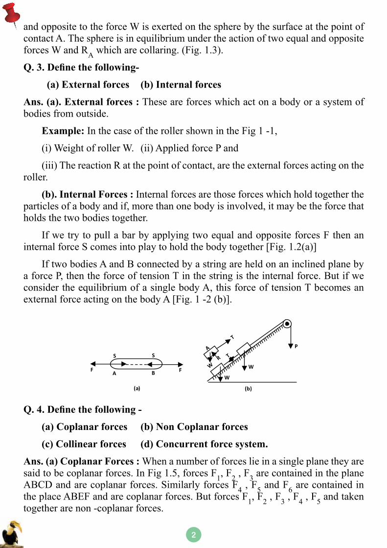
and opposite to the force W is exerted on the sphere by the surface at the point of contact A. The sphere is in equilibrium under the action of two equal and opposite forces W and RA which are collaring. (Fig. 1.3).
Q. 3. Define the following-
(a) External forces (b) Internal forces
Ans. (a). External forces : These are forces which act on a body or a system of bodies from outside.
Example: In the case of the roller shown in the Fig 1 -1,
(i) Weight of roller W. (ii) Applied force P and
(iii) The reaction R at the point of contact, are the external forces acting on the roller.
(b). Internal Forces : Internal forces are those forces which hold together the particles of a body and if, more than one body is involved, it may be the force that holds the two bodies together.
If we try to pull a bar by applying two equal and opposite forces F then an internal force S comes into play to hold the body together [Fig. 1.2(a)]
If two bodies A and B connected by a string are held on an inclined plane by a force P, then the force of tension T in the string is the internal force. But if we consider the equilibrium of a single body A, this force of tension T becomes an external force acting on the body A [Fig. 1 -2 (b)].
S S
A BF F
(a)
P
W
W
(b)
Q. 4. Define the following -
(a) Coplanar forces (b) Non Coplanar forces
(c) Collinear forces (d) Concurrent force system.
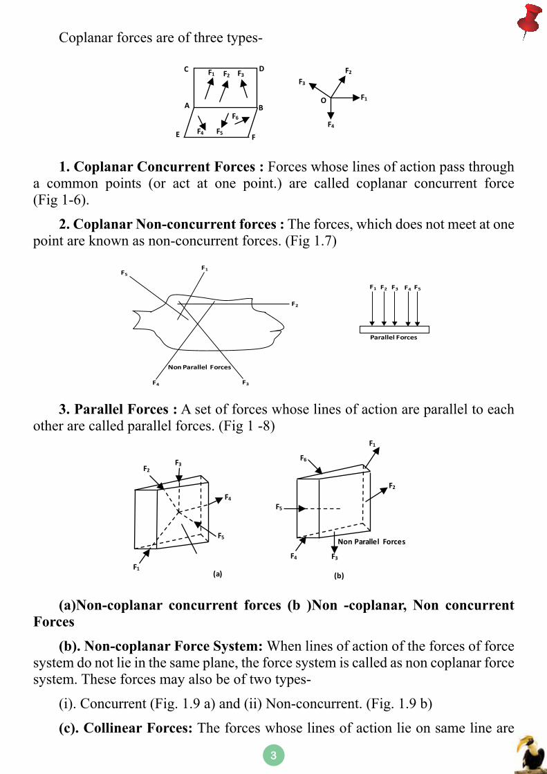
Ans. (a) Coplanar Forces : When a number of forces lie in a single plane they are said to be coplanar forces. In Fig 1.5, forces F1, F2 , F3 are contained in the plane ABCD and are coplanar forces. Similarly forces F4 , F5 and F6 are contained in the place ABEF and are coplanar forces. But forces F1, F2 , F3 , F4 , F5 and taken together are non -coplanar forces.
33
Coplanar forces are of three types-
A
E
C D
B
FF4 F5
F6
F1 F2 F3F3
F2
F1
F4
O
1. Coplanar Concurrent Forces : Forces whose lines of action pass through a common points (or act at one point.) are called coplanar concurrent force (Fig 1-6).
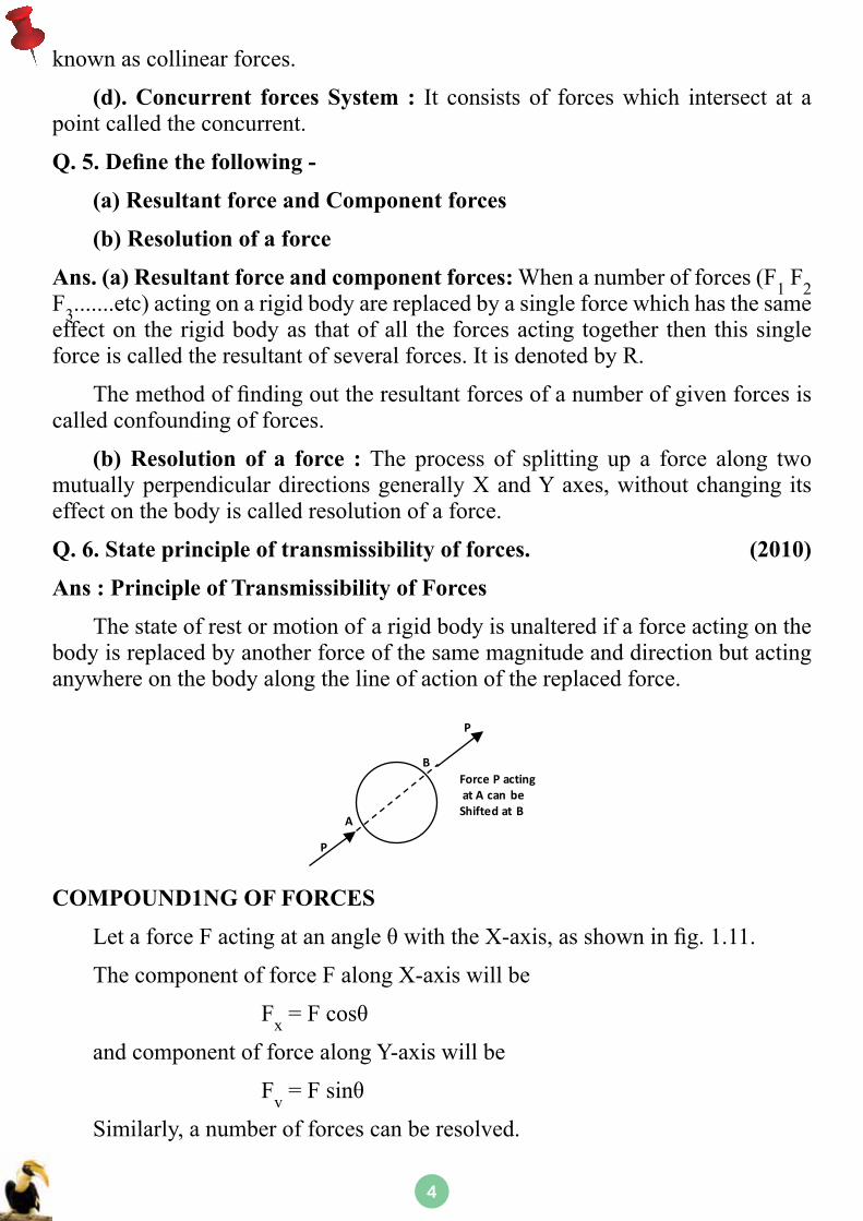
2. Coplanar Non-concurrent forces : The forces, which does not meet at one point are known as non-concurrent forces. (Fig 1.7)
F5F1
F2
F3F4
F1 F2 F3 F4 F5
Parallel Forces
Non Parallel Forces
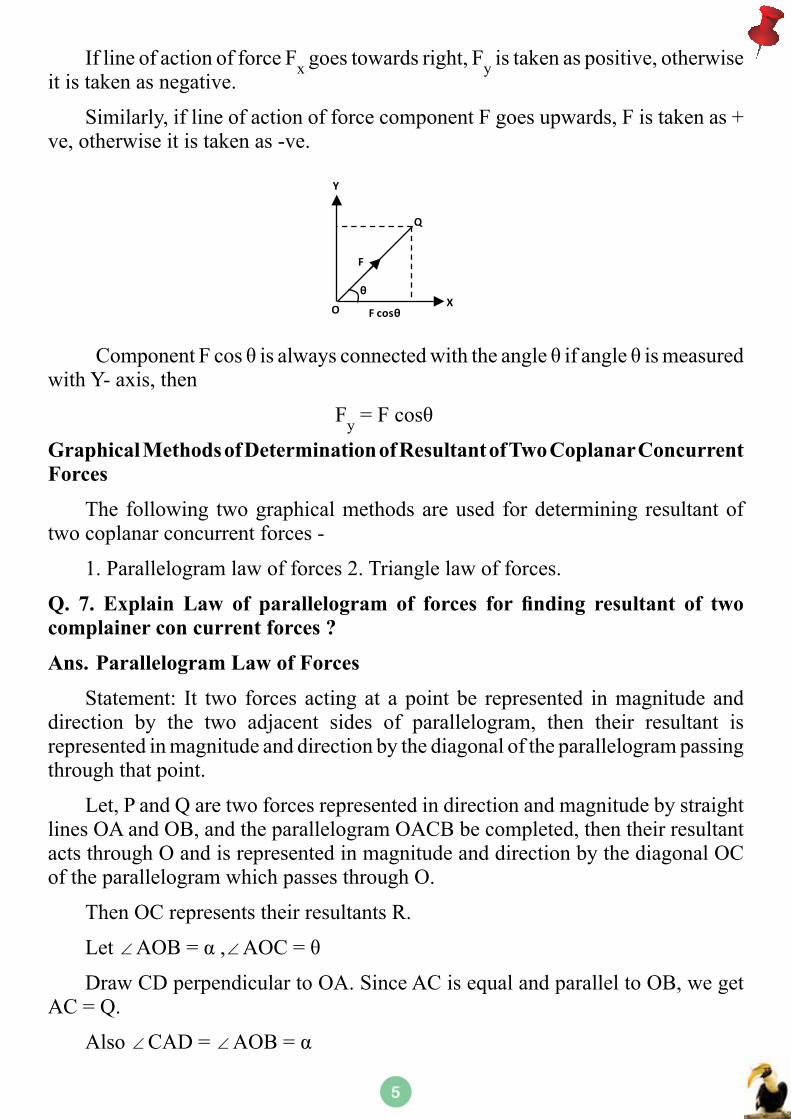
3. Parallel Forces : A set of forces whose lines of action are parallel to each other are called parallel forces. (Fig 1 -8)
F3F2
F1
F4
F5
(a)
F6
F1
F2
F3F4
F5
Non Parallel Forces
(b)
(a)Non-coplanar concurrent forces (b )Non -coplanar, Non concurrent Forces
(b). Non-coplanar Force System: When lines of action of the forces of force system do not lie in the same plane, the force system is called as non coplanar force system. These forces may also be of two types-
(i). Concurrent (Fig. 1.9 a) and (ii) Non-concurrent. (Fig. 1.9 b)
(c). Collinear Forces: The forces whose lines of action lie on same line are
44
known as collinear forces.
(d). Concurrent forces System : It consists of forces which intersect at a point called the concurrent.
Q. 5. Define the following -
(a) Resultant force and Component forces
(b) Resolution of a force
Ans. (a) Resultant force and component forces: When a number of forces (F1 F2 F3.......etc) acting on a rigid body are replaced by a single force which has the same effect on the rigid body as that of all the forces acting together then this single force is called the resultant of several forces. It is denoted by R.
Themethodoffindingouttheresultantforcesofanumberofgivenforcesiscalled confounding of forces.
(b) Resolution of a force : The process of splitting up a force along two mutually perpendicular directions generally X and Y axes, without changing its effect on the body is called resolution of a force.
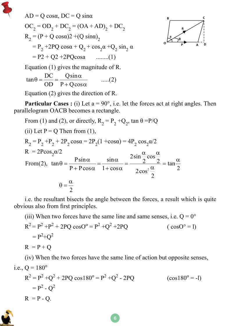
Q. 6. State principle of transmissibility of forces. (2010)
Ans : Principle of Transmissibility of Forces
The state of rest or motion of a rigid body is unaltered if a force acting on the body is replaced by another force of the same magnitude and direction but acting anywhere on the body along the line of action of the replaced force.
P
A
B
P
Force P actingat A can be Shifted at B
COMPOUND1NG OF FORCES
LetaforceFactingatanangleθwiththeX-axis,asshowninfig.1.11.
The component of force F along X-axis will be
Fx=Fcosθ
and component of force along Y-axis will be
Fv=Fsinθ
Similarly, a number of forces can be resolved.
55
If line of action of force Fx goes towards right, Fy is taken as positive, otherwise it is taken as negative.
Similarly, if line of action of force component F goes upwards, F is taken as + ve, otherwise it is taken as -ve.
Y
Q
OX
F
θ
F cosθ
ComponentFcosθisalwaysconnectedwiththeangleθifangleθismeasuredwith Y- axis, then
Fy=Fcosθ
Graphical Methods of Determination of Resultant of Two Coplanar Concurrent Forces
The following two graphical methods are used for determining resultant of two coplanar concurrent forces -
1. Parallelogram law of forces 2. Triangle law of forces.
Q. 7. Explain Law of parallelogram of forces for finding resultant of two complainer con current forces ?
Ans. Parallelogram Law of Forces
Statement: It two forces acting at a point be represented in magnitude and direction by the two adjacent sides of parallelogram, then their resultant is represented in magnitude and direction by the diagonal of the parallelogram passing through that point.
Let, P and Q are two forces represented in direction and magnitude by straight lines OA and OB, and the parallelogram OACB be completed, then their resultant acts through O and is represented in magnitude and direction by the diagonal OC of the parallelogram which passes through O.
Then OC represents their resultants R.
Let ∠AOB=α,∠AOC=θ
Draw CD perpendicular to OA. Since AC is equal and parallel to OB, we get AC = Q.
Also ∠CAD = ∠AOB=α
66
AD=Qcosα,DC=Qsinα
OC2 = OD2 + DC2 = (OA + AD)2 + DC2
R2=(P+Qcosα)2+(Qsinα)2 = P2+2PQcosα+Q2 + cos2α+Q2 sin2α
aθ
B
O
C
A D
R
P
= P2 + Q2 +2PQcosa ........(1)
Equation (1) gives the magnitude of R.
Equation (2) gives the direction of R.
Particular Cases : (i) Let a = 90°, i.e. let the forces act at right angles. Then parallelogram OACB becomes a rectangle.
From (1) and (2), or directly, R2 = P2 +Q2,tanθ=P/Q
(ii) Let P = Q Then from (1),
R2 = P2 +P2 + 2P2 cosα=2P2(1+cosα)=4P2 cos2α/2
R = 2Pcos2α/2
2α
θ =
i.e. the resultant bisects the angle between the forces, a result which is quite obviousalsofromfirstprinciples.
(iii) When two forces have the same line and same senses, i.e. Q = 0°
R2 = P2 +P2 + 2PQ cosOo = P2 +Q2 +2PQ ( cosO° = l)
= P2+Q2
R = P + Q
(iv) When the two forces have the same line of action but opposite senses,
i.e., Q = 180o
R2 = P2 +Q2 + 2PQ cos180o = P2 +Q2 - 2PQ (cos180o = -l)
= P2 - Q2
R = P - Q.
DC Qsintan .....(2)OD P Qcos
αθ = =
+ α
2
2sin cosPsin sin 2 2From(2), tan tanP Pcos 1 cos 22cos
2
α αα α α
θ = = = =α+ α + α
77
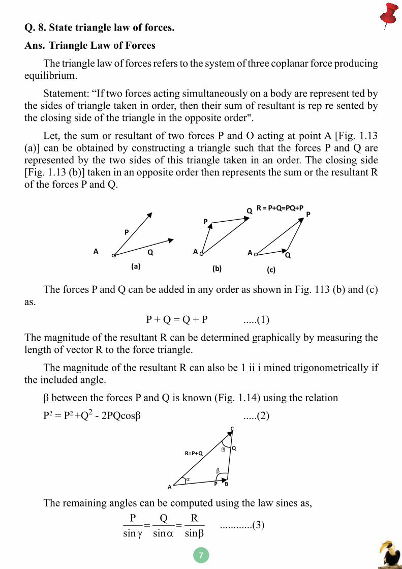
Q. 8. State triangle law of forces.
Ans. Triangle Law of Forces
The triangle law of forces refers to the system of three coplanar force producing equilibrium.
Statement: “If two forces acting simultaneously on a body are represent ted by the sides of triangle taken in order, then their sum of resultant is rep re sented by the closing side of the triangle in the opposite order".
Let, the sum or resultant of two forces P and O acting at point A [Fig. 1.13 (a)] can be obtained by constructing a triangle such that the forces P and Q are represented by the two sides of this triangle taken in an order. The closing side [Fig. 1.13 (b)] taken in an opposite order then represents the sum or the resultant R of the forces P and Q.
P
A Q
PQ
A A Q
PR = P+Q=PQ+P
(a) (b) (c)
The forces P and Q can be added in any order as shown in Fig. 113 (b) and (c) as.
P + Q = Q + P .....(1)
The magnitude of the resultant R can be determined graphically by measuring the length of vector R to the force triangle.
The magnitude of the resultant R can also be 1 ii i mined trigonometrically if the included angle.
βbetweentheforcesPandQisknown(Fig.1.14)usingtherelation
P2 = P2 +Q2-2PQcosβ .....(2)
A BP
C
QR=P+Q
β
ϒ
α
The remaining angles can be computed using the law sines as, P Q R ............(3)
sin sin sin= =
γ α β
88
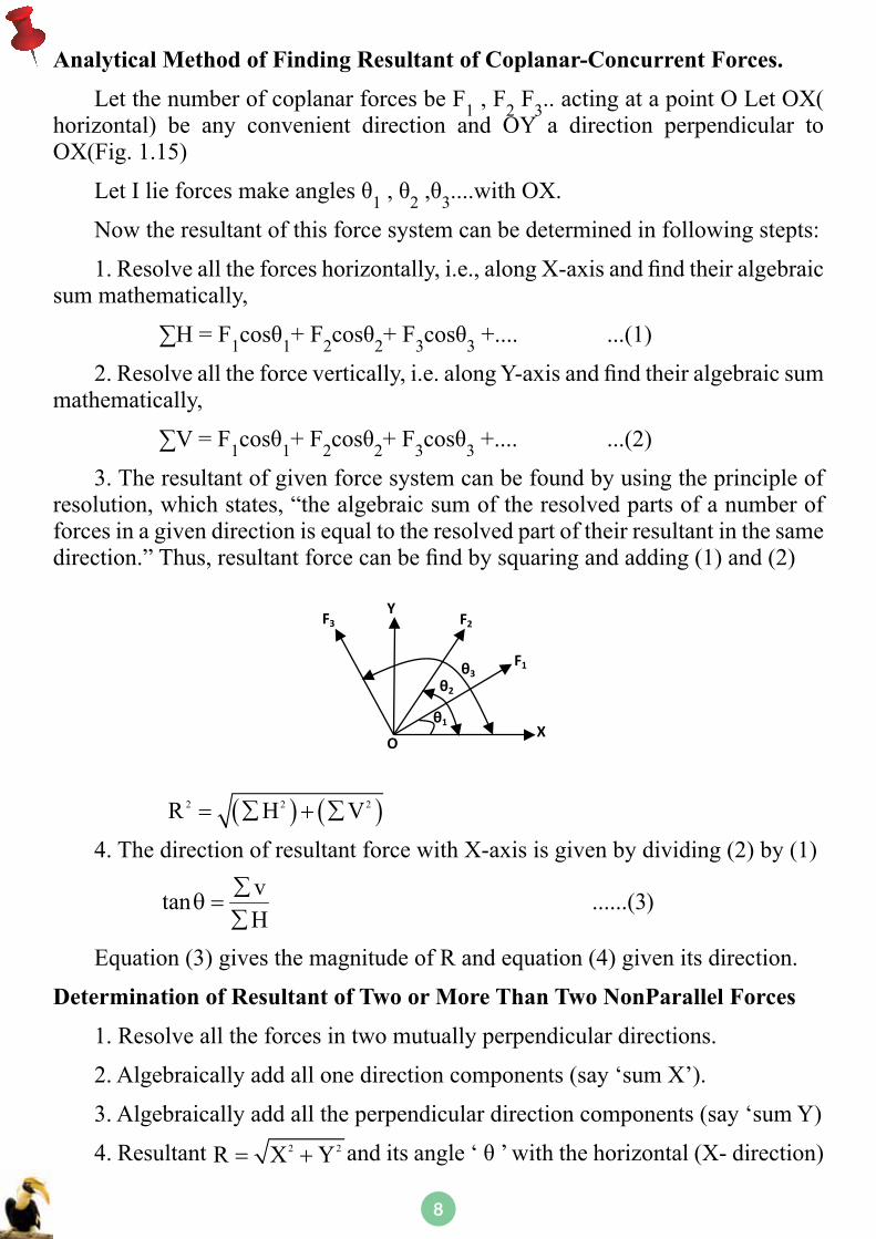
Analytical Method of Finding Resultant of Coplanar-Concurrent Forces.
Let the number of coplanar forces be F1 , F2 F3.. acting at a point O Let OX( horizontal) be any convenient direction and OY a direction perpendicular to OX(Fig. 1.15)
LetIlieforcesmakeanglesθ1,θ2,θ3....with OX.
Now the resultant of this force system can be determined in following stepts:
1.Resolvealltheforceshorizontally,i.e.,alongX-axisandfindtheiralgebraicsum mathematically,
∑H=F1cosθ1+ F2cosθ2+ F3cosθ3 +.... ...(1)
2.Resolvealltheforcevertically,i.e.alongY-axisandfindtheiralgebraicsummathematically,
∑V=F1cosθ1+ F2cosθ2+ F3cosθ3 +.... ...(2)
3. The resultant of given force system can be found by using the principle of resolution, which states, “the algebraic sum of the resolved parts of a number of forces in a given direction is equal to the resolved part of their resultant in the same direction.”Thus,resultantforcecanbefindbysquaringandadding(1)and(2)
F3
O
YF2
F1
X
θ3θ2
θ1
( ) ( )2 2 2R H V= ∑ + ∑
4. The direction of resultant force with X-axis is given by dividing (2) by (1)
vtan ......(3)H
∑θ =
∑
Equation (3) gives the magnitude of R and equation (4) given its direction.
Determination of Resultant of Two or More Than Two NonParallel Forces
1. Resolve all the forces in two mutually perpendicular directions.
2. Algebraically add all one direction components (say ‘sum X’).
3. Algebraically add all the perpendicular direction components (say ‘sum Y)
4. Resultant anditsangle‘θ’withthehorizontal(X-direction)2 2R X Y= +
99
is given by
1 YtanX
− θ =
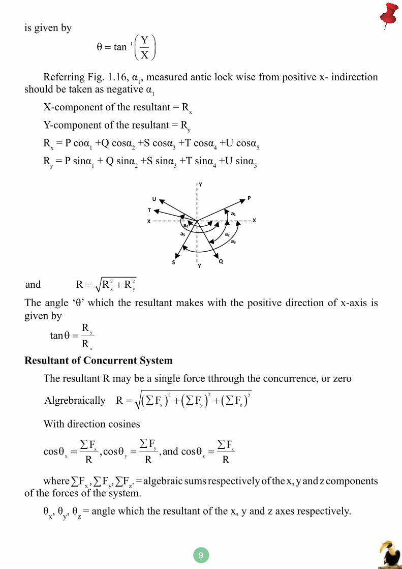
ReferringFig.1.16,α1, measured antic lock wise from positive x- indirection shouldbetakenasnegativeα1
X-component of the resultant = Rx
Y-component of the resultant = Ry
Rx=Pcoα1+Qcosα2+Scosα3+Tcosα4+Ucosα5
Ry=Psinα1+Qsinα2+Ssinα3+Tsinα4+Usinα5
U
T
X
Y
a4
a5
a1
a2
a3
SY
Q
X
P
2 2x yand R R R= +
Theangle ‘θ’which the resultantmakeswith thepositivedirectionofx-axis isgiven by
y
x
Rtan
Rθ =
Resultant of Concurrent System
The resultant R may be a single force tthrough the concurrence, or zero
With direction cosines
where∑Fx,∑Fy,∑Fz. = algebraic sums respectively of the x, y and z components of the forces of the system.
θx,θy,θz = angle which the resultant of the x, y and z axes respectively.
( ) ( ) ( )22 2
x y zAlgrebraically R F F F= ∑ + ∑ + ∑
yx zx y z
FF Fcos ,cos ,and cosR R R
∑∑ ∑θ = θ = θ =
Bookmark - Engineering Mechanics -CSVTU - Previous Year Solved Question
Paper
Publisher : Faculty Notes Author :
Type the URL : http://www.kopykitab.com/product/112
Get this eBook