the history of liquid-crystal displays - proceedings of...
TRANSCRIPT
The History of Liquid-Crystal Displays
HIROHISA KAWAMOTO, FELLOW, IEEE
Invited Paper
The modern history of liquid crystals has been dominated bythe development of electronic displays. These developments beganin 1964, when Heilmeier of RCA Laboratories discovered theguest-host mode and the dynamic-scattering mode. He thoughta wall-sized flat-panel color TV was just around the corner.From that point on, twisted-nematic (TN) mode, super TN mode,amorphous-Si field-effect transistor, and room-temperature liquidcrystals were developed. In the beginning, liquid-crystal displays(LCDs) were limited to niche applications such as small-size dis-plays for digital watches, pocket calculators, and small handhelddevices. That all changed with the development of the notebookcomputer industry. In 1988, Washizuka et al. of Sharp Corporationdemonstrated an active-matrix full-color full-motion 14-in displayusing a thin-film-transistor array. The electronics industries nowrecognized that Heilmeier’s 25-year dream of a wall-hanging tele-vision had become reality. LCDs could be used to replace existingcathode ray tubes. Through the cooperation and competition ofmany electronics giants, the LCD industry was firmly established.
Keywords—Active matrix, amorphous silicon, azoxy, bire-fringence, cholesteric, cyanobiphenyl, dielectric anisotropy,digital watch, DSM, DSTN, ester, Fergason, Gray, guest host,Heilmeier, Helfrich, history, LCD, liquid crystals, MBBA, Nehring,nematic, PCH, pocket calculator, poly silicon, Raynes, rubbing,Schadt, Scheffer, Seiko, Sharp, STN, TFT, TN mode, transmissionminimum, Wada, wall-hanging television, Washizuka, Williamsdomain, Yamazaki.
I. INTRODUCTION
The development of liquid-crystal displays (LCD) pro-ceeded from early successes like the pocket calculator tothe major milestone of a flat-panel television display youcan hang on a wall. The history of that development spansthe world’s major industrial centers: the U.S., Japan, andEurope. I was fortunate to be a part of that history. WhenI joined RCA Laboratories at the David Sarnoff ResearchCenter in April 1970, RCA was curtailing its efforts inliquid-crystal activities, but I had the opportunity to witnessthe developments there before the program’s group head,George Heilmeier, left for Capitol Hill as a White House
Manuscript received October 20, 2000; revised August 3, 2001.The author is with Silicon Image Inc., Nara Gakuen-Mae, Japan (e-mail:
[email protected]).Publisher Item Identifier S 0018-9219(02)03951-8.
Fellow. Then, in 1985, I joined the Sharp Corporation inJapan and met Tomio Wada, the man who developed theworld’s first liquid-crystal product, a pocket calculator, in1973. At Sharp, I also witnessed major development effortsin LCDs at the Tenri Advanced Development Center. In1990, I participated in the founding of the European Labo-ratories at Oxford, U.K., and in 1992, we welcomed PeterRaynes, known for his contributions to the applications ofcyanobiphenyls, to the Laboratories. Through discussionswith him, I learned about the achievements of British andEuropean scientists.
The modern history of liquid crystals is predominantly thehistory of the development of electronic displays made ofliquid crystals. The developments started when a dynamic-scattering mode (DSM) was discovered in 1964. Manufac-turers of LCDs had been minor-league members of the elec-tronic display industry and served a niche market, supplyingsmall-size displays primarily to pocket calculators and dig-ital watches. A major milestone was reached in 1988 whena 14-in active-matrix (AM) thin-film-transistor (TFT) dis-play was demonstrated. The electronics industries then rec-ognized that the dream of a wall-hanging television had be-come a reality, thus, promoting LCD manufacturers to the“major leagues” in the electronics industry. By 2000, theLCD industry had caught up to the giant cathode ray tube(CRT) industry. In this paper, I focus on the 25 years ofLCD developments that gave birth to the present-day LCDindustry. In writing this paper, I interviewed 37 scientists andengineers scattered throughout the world. Each section of thearticle concentrates on a key technical item that led to the ul-timate goal—the flat-panel television.
What had been an obscure general and scientific curiosityfor 80 years suddenly became the center of attention as theresult of a new invention, spawning a new industry projectedto reach 40 billion dollars by the year 2006. The historyof LCDs is a story of the hard work, disappointments, andsuccesses of worldwide competition and cooperation thatencompassed the U.S., Europe, and Japan. Each industrialcenter contributed its particular strengths: in America, itwas the quickness of forming new ideas and demonstratingtheir feasibility; in Europe, it was the fundamental science
0018-9219/02$17.00 © 2002 IEEE
460 PROCEEDINGS OF THE IEEE, VOL. 90, NO. 4, APRIL 2002
and synthesis of basic materials; and in Japan, it was theprocess of perfecting implementation and moving it to theproduction line.
II. DISCOVERY OFLIQUID CRYSTALS AND THEIR
FUNDAMENTALS—THE NAME “L IQUID CRYSTALS” WAS
BORN IN GERMANY
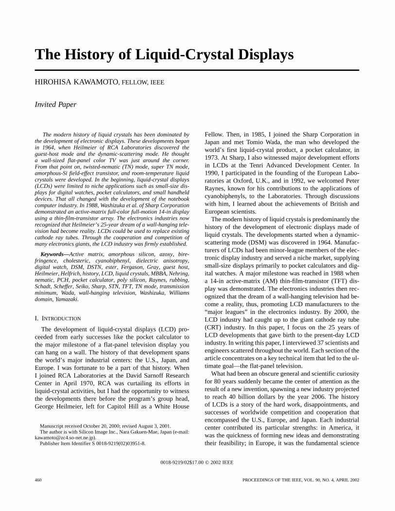
As a material’s temperature is raised, it generally changesstate from solid to liquid to gaseous. It is generally be-lieved that an Austrian botanist, Friedrich Reinitzer [see,e.g., Fig. 1(a)], first observed liquid crystals in 1888. Hediscovered a strange material that exhibited a mesophasebetween solid state and liquid state [1]. At a temperatureof 145 C, it melted, becoming cloudy white and viscous.At a temperature of 179C, it became isotropic and clear.The material he discovered was cholesteryl benzoate. OnMarch 14, 1889, he wrote a letter to Otto Lehmann [see, e.g.,Fig. 1(b)], Professor of Physics at the Technical UniversityKarlsruhe of Germany, telling him about the two meltingpoints. Lehmann studied the material and discovered that theliquid at the mesophase exhibited a double refraction effect,characteristic of a crystal. Because it shared characteristicsof both liquid and crystal, he named it “fliessende krystalle”and the name “liquid crystal” was born [2].
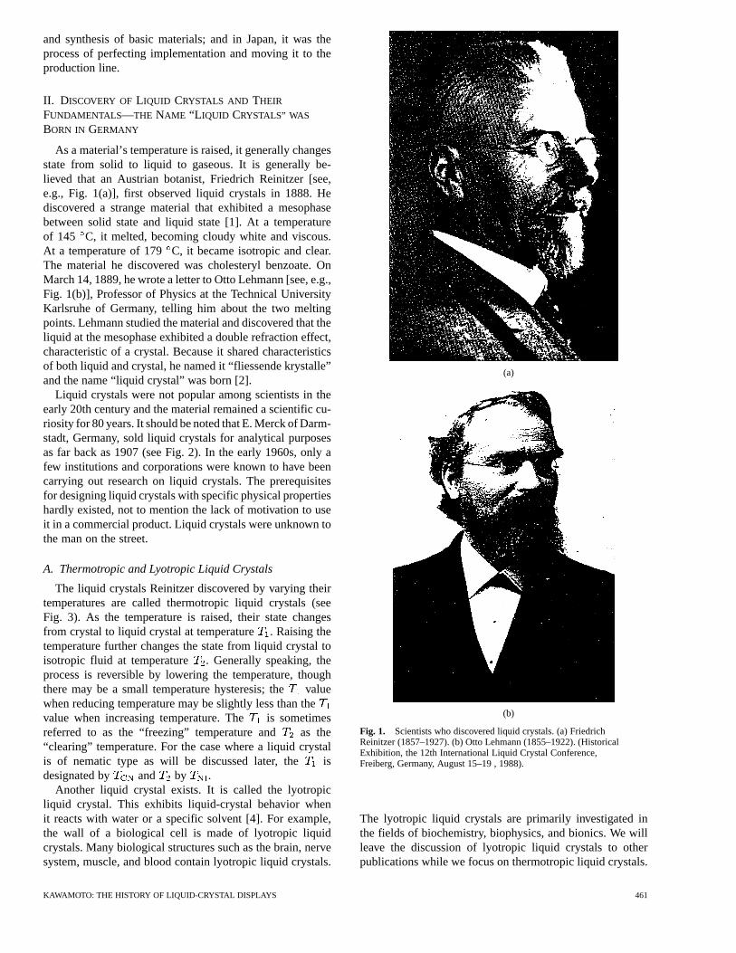
Liquid crystals were not popular among scientists in theearly 20th century and the material remained a scientific cu-riosity for 80 years. It should be noted that E. Merck of Darm-stadt, Germany, sold liquid crystals for analytical purposesas far back as 1907 (see Fig. 2). In the early 1960s, only afew institutions and corporations were known to have beencarrying out research on liquid crystals. The prerequisitesfor designing liquid crystals with specific physical propertieshardly existed, not to mention the lack of motivation to useit in a commercial product. Liquid crystals were unknown tothe man on the street.
A. Thermotropic and Lyotropic Liquid Crystals
The liquid crystals Reinitzer discovered by varying theirtemperatures are called thermotropic liquid crystals (seeFig. 3). As the temperature is raised, their state changesfrom crystal to liquid crystal at temperature. Raising thetemperature further changes the state from liquid crystal toisotropic fluid at temperature . Generally speaking, theprocess is reversible by lowering the temperature, thoughthere may be a small temperature hysteresis; thevaluewhen reducing temperature may be slightly less than thevalue when increasing temperature. The is sometimesreferred to as the “freezing” temperature and as the“clearing” temperature. For the case where a liquid crystalis of nematic type as will be discussed later, the isdesignated by and by .
Another liquid crystal exists. It is called the lyotropicliquid crystal. This exhibits liquid-crystal behavior whenit reacts with water or a specific solvent [4]. For example,the wall of a biological cell is made of lyotropic liquidcrystals. Many biological structures such as the brain, nervesystem, muscle, and blood contain lyotropic liquid crystals.
(a)
(b)
Fig. 1. Scientists who discovered liquid crystals. (a) FriedrichReinitzer (1857–1927). (b) Otto Lehmann (1855–1922). (HistoricalExhibition, the 12th International Liquid Crystal Conference,Freiberg, Germany, August 15–19 , 1988).
The lyotropic liquid crystals are primarily investigated inthe fields of biochemistry, biophysics, and bionics. We willleave the discussion of lyotropic liquid crystals to otherpublications while we focus on thermotropic liquid crystals.
KAWAMOTO: THE HISTORY OF LIQUID-CRYSTAL DISPLAYS 461
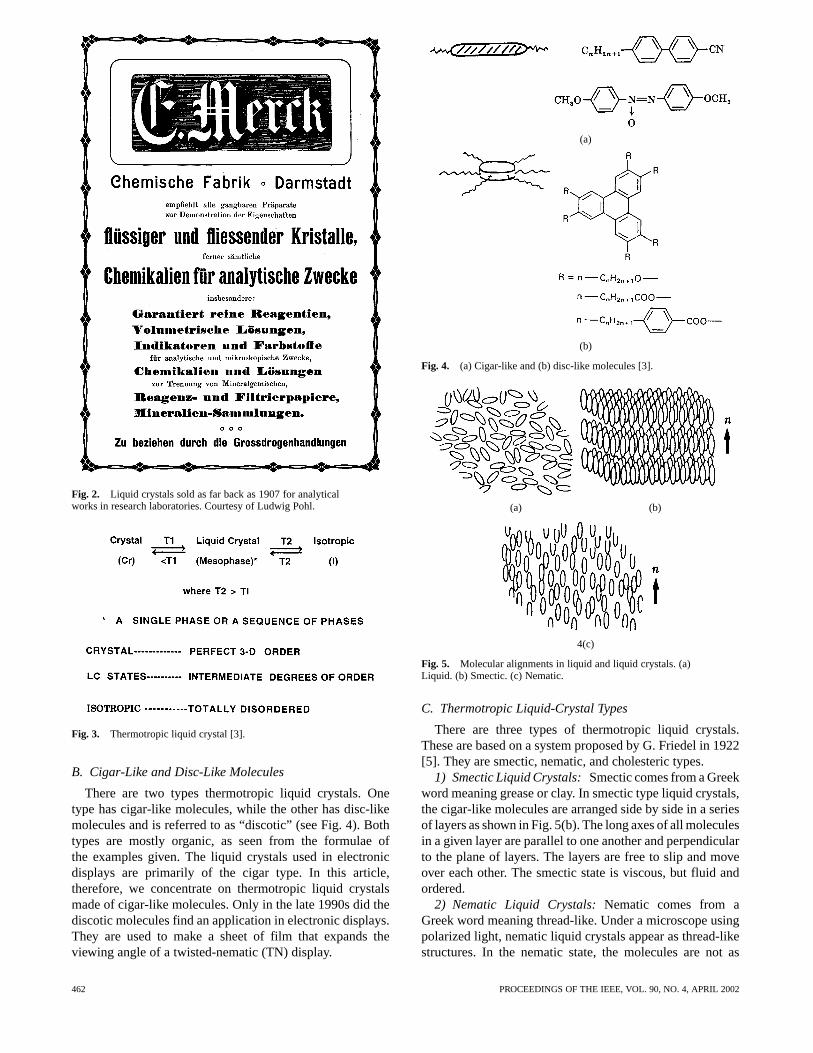
Fig. 2. Liquid crystals sold as far back as 1907 for analyticalworks in research laboratories. Courtesy of Ludwig Pohl.
Fig. 3. Thermotropic liquid crystal [3].
B. Cigar-Like and Disc-Like Molecules
There are two types thermotropic liquid crystals. Onetype has cigar-like molecules, while the other has disc-likemolecules and is referred to as “discotic” (see Fig. 4). Bothtypes are mostly organic, as seen from the formulae ofthe examples given. The liquid crystals used in electronicdisplays are primarily of the cigar type. In this article,therefore, we concentrate on thermotropic liquid crystalsmade of cigar-like molecules. Only in the late 1990s did thediscotic molecules find an application in electronic displays.They are used to make a sheet of film that expands theviewing angle of a twisted-nematic (TN) display.
(a)
(b)
Fig. 4. (a) Cigar-like and (b) disc-like molecules [3].
(a) (b)
4(c)
Fig. 5. Molecular alignments in liquid and liquid crystals. (a)Liquid. (b) Smectic. (c) Nematic.
C. Thermotropic Liquid-Crystal Types
There are three types of thermotropic liquid crystals.These are based on a system proposed by G. Friedel in 1922[5]. They are smectic, nematic, and cholesteric types.
1) Smectic Liquid Crystals:Smectic comes from a Greekword meaning grease or clay. In smectic type liquid crystals,the cigar-like molecules are arranged side by side in a seriesof layers as shown in Fig. 5(b). The long axes of all moleculesin a given layer are parallel to one another and perpendicularto the plane of layers. The layers are free to slip and moveover each other. The smectic state is viscous, but fluid andordered.
2) Nematic Liquid Crystals:Nematic comes from aGreek word meaning thread-like. Under a microscope usingpolarized light, nematic liquid crystals appear as thread-likestructures. In the nematic state, the molecules are not as
462 PROCEEDINGS OF THE IEEE, VOL. 90, NO. 4, APRIL 2002
(a) (b) (c)
Fig. 6. Three molecular alignments of nematic liquid crystals [4]. (a) Splay. (b) Twist. (c) Bend.
highly ordered as in the smectic state, but they maintain theirparallel order [see, e.g., Fig. 5(c)]. On average, the nematicliquid crystals are aligned in one direction. The direction isrepresented by a vector called a director. Liquid crystalsused in electronic displays are primarily of the nematic type.
Because of its specific molecular alignment, nematicliquid crystals exhibit anisotropic physical characteristics;their refractive index, dielectric constant, permeability, elec-trical conductivity, and viscosity measured in the directionof the long axis are different from those measured in theplane normal to the long axis. In nematic liquid crystals,the refractive index along the director axis is almost alwayslarger than along the perpendicular axes. The electricalconductivity along the director axis is generally larger thanalong the perpendicular axes. The permeability is generallynegative and its absolute value along the director axis issmaller than along the perpendicular axes.
3) Cholesteric Liquid Crystals:These materials are dis-cussed later in this section.
D. Elasticity
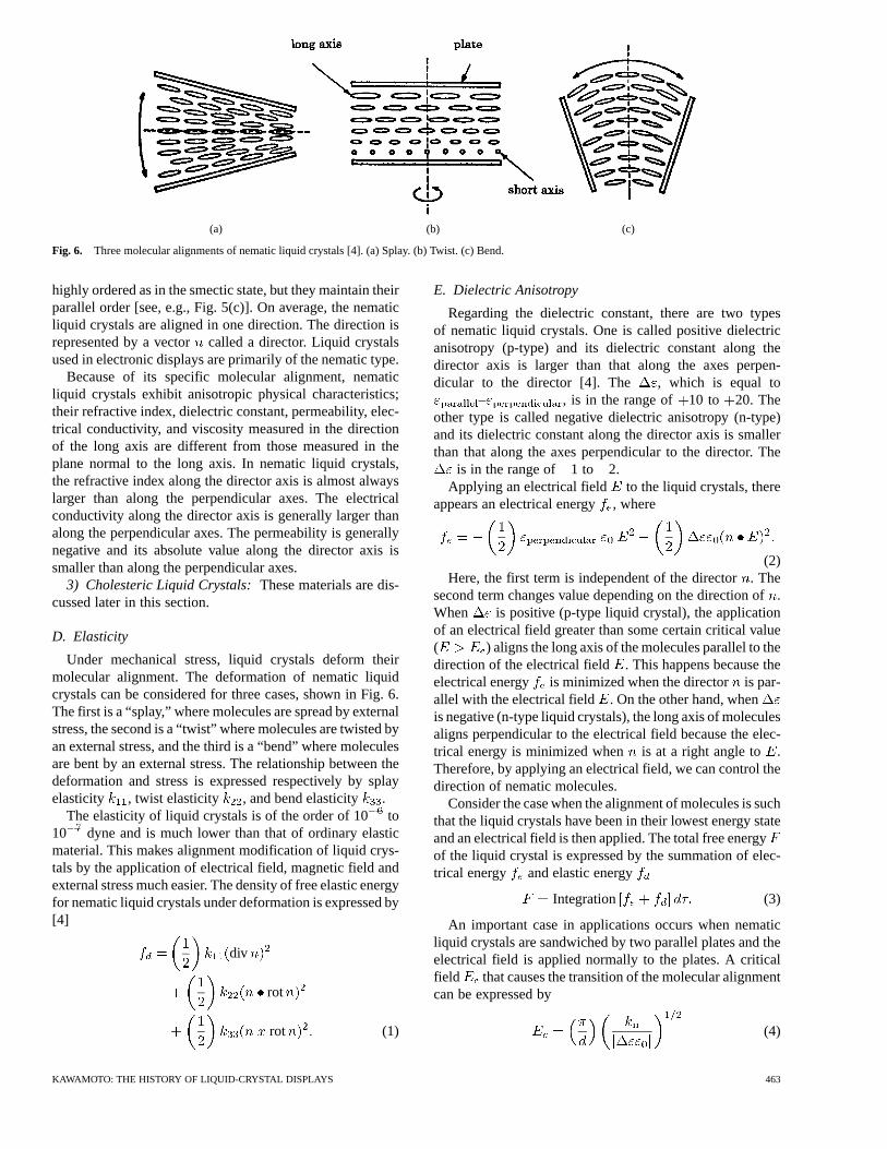
Under mechanical stress, liquid crystals deform theirmolecular alignment. The deformation of nematic liquidcrystals can be considered for three cases, shown in Fig. 6.The first is a “splay,” where molecules are spread by externalstress, the second is a “twist” where molecules are twisted byan external stress, and the third is a “bend” where moleculesare bent by an external stress. The relationship between thedeformation and stress is expressed respectively by splayelasticity , twist elasticity , and bend elasticity .
The elasticity of liquid crystals is of the order of 10to10 dyne and is much lower than that of ordinary elasticmaterial. This makes alignment modification of liquid crys-tals by the application of electrical field, magnetic field andexternal stress much easier. The density of free elastic energyfor nematic liquid crystals under deformation is expressed by[4]
div
rot
rot (1)
E. Dielectric Anisotropy
Regarding the dielectric constant, there are two typesof nematic liquid crystals. One is called positive dielectricanisotropy (p-type) and its dielectric constant along thedirector axis is larger than that along the axes perpen-dicular to the director [4]. The , which is equal to
– , is in the range of 10 to 20. Theother type is called negative dielectric anisotropy (n-type)and its dielectric constant along the director axis is smallerthan that along the axes perpendicular to the director. The
is in the range of 1 to 2.Applying an electrical field to the liquid crystals, there
appears an electrical energy, where
(2)Here, the first term is independent of the director. The
second term changes value depending on the direction of.When is positive (p-type liquid crystal), the applicationof an electrical field greater than some certain critical value( ) aligns the long axis of the molecules parallel to thedirection of the electrical field . This happens because theelectrical energy is minimized when the director is par-allel with the electrical field . On the other hand, whenis negative (n-type liquid crystals), the long axis of moleculesaligns perpendicular to the electrical field because the elec-trical energy is minimized when is at a right angle to .Therefore, by applying an electrical field, we can control thedirection of nematic molecules.
Consider the case when the alignment of molecules is suchthat the liquid crystals have been in their lowest energy stateand an electrical field is then applied. The total free energyof the liquid crystal is expressed by the summation of elec-trical energy and elastic energy
Integration (3)
An important case in applications occurs when nematicliquid crystals are sandwiched by two parallel plates and theelectrical field is applied normally to the plates. A criticalfield that causes the transition of the molecular alignmentcan be expressed by
(4)
KAWAMOTO: THE HISTORY OF LIQUID-CRYSTAL DISPLAYS 463
where is the spacing of the plates. When the base state of themolecular alignment is homogeneous, and whenthe alignment is twisted, . Whenthe liquid crystals are positive and the alignment is twistedas shown in Fig. 6(b), the threshold voltage for transition is
(5)
F. Birefringence
Because of its double refraction or birefringence property,a liquid crystal exhibits the following optical characteristics[4].
1) It redirects the direction of incoming light along thelong axis (director ) of the liquid crystal.
2) It changes the state of polarization (from linear, ellipse,or circular polarization to one of linear, ellipse andcircular polarizations) and/or changes the direction ofpolarization.
Liquid crystals are not as rigid as solids and are easily re-oriented, realigned, or deformed by applying electrical fields,magnetic fields, heat, and/or mechanical stresses. Accord-ingly, the optical characteristics based on the birefringenceare easily affected. These make nematic liquid crystals at-tractive for use in electronic devices. The following sectionstrace the history of how scientists and engineers used suchcharacteristics of nematic liquid crystals to construct elec-tronic displays.
G. Cholesteric Liquid Crystals
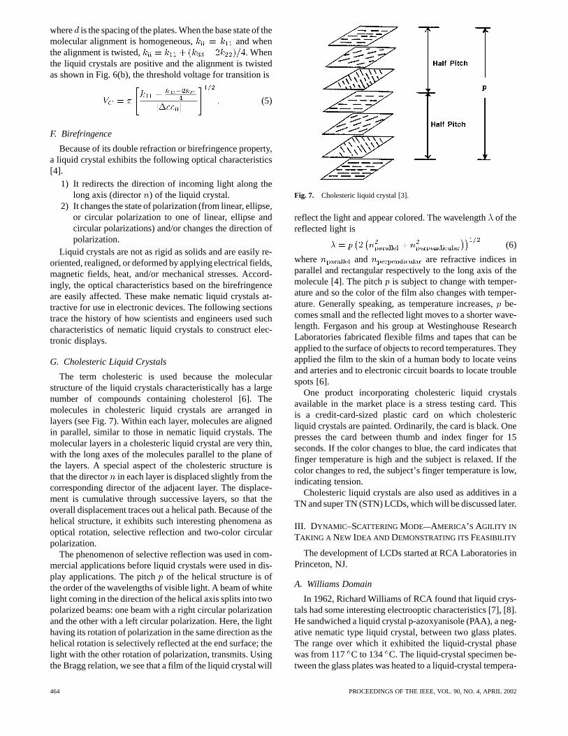
The term cholesteric is used because the molecularstructure of the liquid crystals characteristically has a largenumber of compounds containing cholesterol [6]. Themolecules in cholesteric liquid crystals are arranged inlayers (see Fig. 7). Within each layer, molecules are alignedin parallel, similar to those in nematic liquid crystals. Themolecular layers in a cholesteric liquid crystal are very thin,with the long axes of the molecules parallel to the plane ofthe layers. A special aspect of the cholesteric structure isthat the director in each layer is displaced slightly from thecorresponding director of the adjacent layer. The displace-ment is cumulative through successive layers, so that theoverall displacement traces out a helical path. Because of thehelical structure, it exhibits such interesting phenomena asoptical rotation, selective reflection and two-color circularpolarization.
The phenomenon of selective reflection was used in com-mercial applications before liquid crystals were used in dis-play applications. The pitch of the helical structure is ofthe order of the wavelengths of visible light. A beam of whitelight coming in the direction of the helical axis splits into twopolarized beams: one beam with a right circular polarizationand the other with a left circular polarization. Here, the lighthaving its rotation of polarization in the same direction as thehelical rotation is selectively reflected at the end surface; thelight with the other rotation of polarization, transmits. Usingthe Bragg relation, we see that a film of the liquid crystal will
Fig. 7. Cholesteric liquid crystal [3].
reflect the light and appear colored. The wavelengthof thereflected light is
(6)
where and are refractive indices inparallel and rectangular respectively to the long axis of themolecule [4]. The pitch is subject to change with temper-ature and so the color of the film also changes with temper-ature. Generally speaking, as temperature increases,be-comes small and the reflected light moves to a shorter wave-length. Fergason and his group at Westinghouse ResearchLaboratories fabricated flexible films and tapes that can beapplied to the surface of objects to record temperatures. Theyapplied the film to the skin of a human body to locate veinsand arteries and to electronic circuit boards to locate troublespots [6].
One product incorporating cholesteric liquid crystalsavailable in the market place is a stress testing card. Thisis a credit-card-sized plastic card on which cholestericliquid crystals are painted. Ordinarily, the card is black. Onepresses the card between thumb and index finger for 15seconds. If the color changes to blue, the card indicates thatfinger temperature is high and the subject is relaxed. If thecolor changes to red, the subject’s finger temperature is low,indicating tension.
Cholesteric liquid crystals are also used as additives in aTN and super TN (STN) LCDs, which will be discussed later.
III. D YNAMIC –SCATTERING MODE—AMERICA’SAGILITY IN
TAKING A NEW IDEA AND DEMONSTRATING ITSFEASIBILITY
The development of LCDs started at RCA Laboratories inPrinceton, NJ.
A. Williams Domain
In 1962, Richard Williams of RCA found that liquid crys-tals had some interesting electrooptic characteristics [7], [8].He sandwiched a liquid crystal p-azoxyanisole (PAA), a neg-ative nematic type liquid crystal, between two glass plates.The range over which it exhibited the liquid-crystal phasewas from 117 C to 134 C. The liquid-crystal specimen be-tween the glass plates was heated to a liquid-crystal tempera-
464 PROCEEDINGS OF THE IEEE, VOL. 90, NO. 4, APRIL 2002
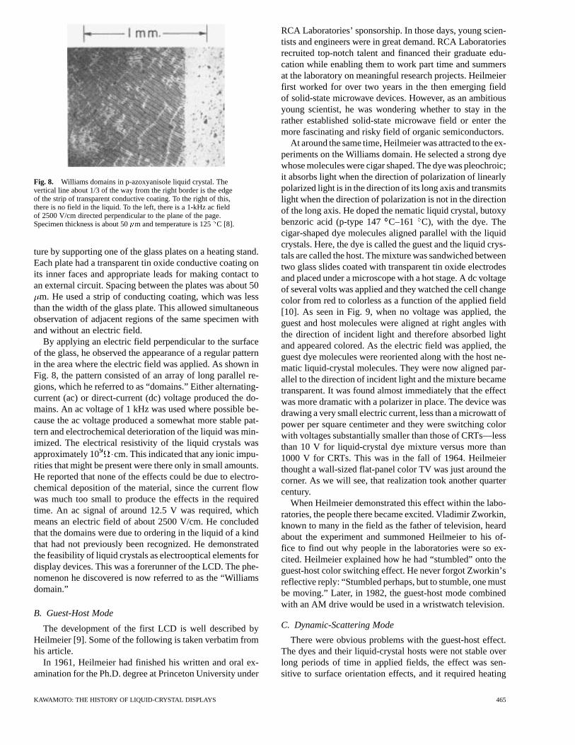
Fig. 8. Williams domains in p-azoxyanisole liquid crystal. Thevertical line about 1/3 of the way from the right border is the edgeof the strip of transparent conductive coating. To the right of this,there is no field in the liquid. To the left, there is a 1-kHz ac fieldof 2500 V/cm directed perpendicular to the plane of the page.Specimen thickness is about 50�m and temperature is 125C [8].
ture by supporting one of the glass plates on a heating stand.Each plate had a transparent tin oxide conductive coating onits inner faces and appropriate leads for making contact toan external circuit. Spacing between the plates was about 50
m. He used a strip of conducting coating, which was lessthan the width of the glass plate. This allowed simultaneousobservation of adjacent regions of the same specimen withand without an electric field.
By applying an electric field perpendicular to the surfaceof the glass, he observed the appearance of a regular patternin the area where the electric field was applied. As shown inFig. 8, the pattern consisted of an array of long parallel re-gions, which he referred to as “domains.” Either alternating-current (ac) or direct-current (dc) voltage produced the do-mains. An ac voltage of 1 kHz was used where possible be-cause the ac voltage produced a somewhat more stable pat-tern and electrochemical deterioration of the liquid was min-imized. The electrical resistivity of the liquid crystals wasapproximately 10 cm. This indicated that any ionic impu-rities that might be present were there only in small amounts.He reported that none of the effects could be due to electro-chemical deposition of the material, since the current flowwas much too small to produce the effects in the requiredtime. An ac signal of around 12.5 V was required, whichmeans an electric field of about 2500 V/cm. He concludedthat the domains were due to ordering in the liquid of a kindthat had not previously been recognized. He demonstratedthe feasibility of liquid crystals as electrooptical elements fordisplay devices. This was a forerunner of the LCD. The phe-nomenon he discovered is now referred to as the “Williamsdomain.”
B. Guest-Host Mode
The development of the first LCD is well described byHeilmeier [9]. Some of the following is taken verbatim fromhis article.
In 1961, Heilmeier had finished his written and oral ex-amination for the Ph.D. degree at Princeton University under
RCA Laboratories’ sponsorship. In those days, young scien-tists and engineers were in great demand. RCA Laboratoriesrecruited top-notch talent and financed their graduate edu-cation while enabling them to work part time and summersat the laboratory on meaningful research projects. Heilmeierfirst worked for over two years in the then emerging fieldof solid-state microwave devices. However, as an ambitiousyoung scientist, he was wondering whether to stay in therather established solid-state microwave field or enter themore fascinating and risky field of organic semiconductors.
At around the same time, Heilmeier was attracted to the ex-periments on the Williams domain. He selected a strong dyewhose molecules were cigar shaped. The dye was pleochroic;it absorbs light when the direction of polarization of linearlypolarized light is in the direction of its long axis and transmitslight when the direction of polarization is not in the directionof the long axis. He doped the nematic liquid crystal, butoxybenzoric acid (p-type 147C–161 C), with the dye. Thecigar-shaped dye molecules aligned parallel with the liquidcrystals. Here, the dye is called the guest and the liquid crys-tals are called the host. The mixture was sandwiched betweentwo glass slides coated with transparent tin oxide electrodesand placed under a microscope with a hot stage. A dc voltageof several volts was applied and they watched the cell changecolor from red to colorless as a function of the applied field[10]. As seen in Fig. 9, when no voltage was applied, theguest and host molecules were aligned at right angles withthe direction of incident light and therefore absorbed lightand appeared colored. As the electric field was applied, theguest dye molecules were reoriented along with the host ne-matic liquid-crystal molecules. They were now aligned par-allel to the direction of incident light and the mixture becametransparent. It was found almost immediately that the effectwas more dramatic with a polarizer in place. The device wasdrawing a very small electric current, less than a microwatt ofpower per square centimeter and they were switching colorwith voltages substantially smaller than those of CRTs—lessthan 10 V for liquid-crystal dye mixture versus more than1000 V for CRTs. This was in the fall of 1964. Heilmeierthought a wall-sized flat-panel color TV was just around thecorner. As we will see, that realization took another quartercentury.
When Heilmeier demonstrated this effect within the labo-ratories, the people there became excited. Vladimir Zworkin,known to many in the field as the father of television, heardabout the experiment and summoned Heilmeier to his of-fice to find out why people in the laboratories were so ex-cited. Heilmeier explained how he had “stumbled” onto theguest-host color switching effect. He never forgot Zworkin’sreflective reply: “Stumbled perhaps, but to stumble, one mustbe moving.” Later, in 1982, the guest-host mode combinedwith an AM drive would be used in a wristwatch television.
C. Dynamic-Scattering Mode
There were obvious problems with the guest-host effect.The dyes and their liquid-crystal hosts were not stable overlong periods of time in applied fields, the effect was sen-sitive to surface orientation effects, and it required heating
KAWAMOTO: THE HISTORY OF LIQUID-CRYSTAL DISPLAYS 465
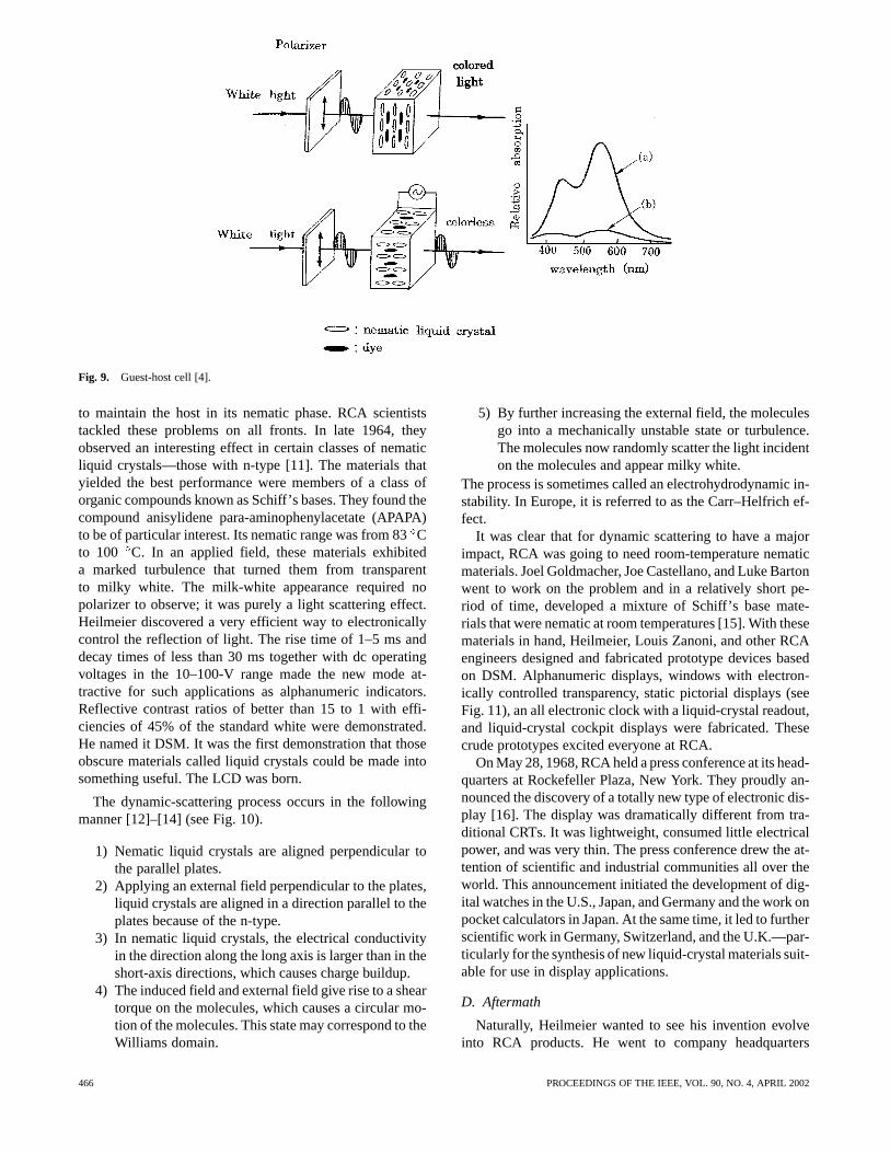
Fig. 9. Guest-host cell [4].
to maintain the host in its nematic phase. RCA scientiststackled these problems on all fronts. In late 1964, theyobserved an interesting effect in certain classes of nematicliquid crystals—those with n-type [11]. The materials thatyielded the best performance were members of a class oforganic compounds known as Schiff’s bases. They found thecompound anisylidene para-aminophenylacetate (APAPA)to be of particular interest. Its nematic range was from 83Cto 100 C. In an applied field, these materials exhibiteda marked turbulence that turned them from transparentto milky white. The milk-white appearance required nopolarizer to observe; it was purely a light scattering effect.Heilmeier discovered a very efficient way to electronicallycontrol the reflection of light. The rise time of 1–5 ms anddecay times of less than 30 ms together with dc operatingvoltages in the 10–100-V range made the new mode at-tractive for such applications as alphanumeric indicators.Reflective contrast ratios of better than 15 to 1 with effi-ciencies of 45% of the standard white were demonstrated.He named it DSM. It was the first demonstration that thoseobscure materials called liquid crystals could be made intosomething useful. The LCD was born.
The dynamic-scattering process occurs in the followingmanner [12]–[14] (see Fig. 10).
1) Nematic liquid crystals are aligned perpendicular tothe parallel plates.
2) Applying an external field perpendicular to the plates,liquid crystals are aligned in a direction parallel to theplates because of the n-type.
3) In nematic liquid crystals, the electrical conductivityin the direction along the long axis is larger than in theshort-axis directions, which causes charge buildup.
4) The induced field and external field give rise to a sheartorque on the molecules, which causes a circular mo-tion of the molecules. This state may correspond to theWilliams domain.
5) By further increasing the external field, the moleculesgo into a mechanically unstable state or turbulence.The molecules now randomly scatter the light incidenton the molecules and appear milky white.
The process is sometimes called an electrohydrodynamic in-stability. In Europe, it is referred to as the Carr–Helfrich ef-fect.
It was clear that for dynamic scattering to have a majorimpact, RCA was going to need room-temperature nematicmaterials. Joel Goldmacher, Joe Castellano, and Luke Bartonwent to work on the problem and in a relatively short pe-riod of time, developed a mixture of Schiff’s base mate-rials that were nematic at room temperatures [15]. With thesematerials in hand, Heilmeier, Louis Zanoni, and other RCAengineers designed and fabricated prototype devices basedon DSM. Alphanumeric displays, windows with electron-ically controlled transparency, static pictorial displays (seeFig. 11), an all electronic clock with a liquid-crystal readout,and liquid-crystal cockpit displays were fabricated. Thesecrude prototypes excited everyone at RCA.
On May 28, 1968, RCA held a press conference at its head-quarters at Rockefeller Plaza, New York. They proudly an-nounced the discovery of a totally new type of electronic dis-play [16]. The display was dramatically different from tra-ditional CRTs. It was lightweight, consumed little electricalpower, and was very thin. The press conference drew the at-tention of scientific and industrial communities all over theworld. This announcement initiated the development of dig-ital watches in the U.S., Japan, and Germany and the work onpocket calculators in Japan. At the same time, it led to furtherscientific work in Germany, Switzerland, and the U.K.—par-ticularly for the synthesis of new liquid-crystal materials suit-able for use in display applications.
D. Aftermath
Naturally, Heilmeier wanted to see his invention evolveinto RCA products. He went to company headquarters
466 PROCEEDINGS OF THE IEEE, VOL. 90, NO. 4, APRIL 2002
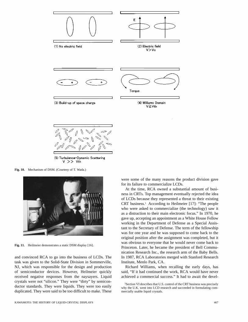
Fig. 10. Mechanism of DSM. (Courtesy of T. Wada.)
Fig. 11. Heilmeier demonstrates a static DSM display [16].
and convinced RCA to go into the business of LCDs. Thetask was given to the Solid-State Division in Sommerville,NJ, which was responsible for the design and productionof semiconductor devices. However, Heilmeier quicklyreceived negative responses from the naysayers. Liquidcrystals were not “silicon.” They were “dirty” by semicon-ductor standards. They were liquids. They were too easilyduplicated. They were said to be too difficult to make. These
were some of the many reasons the product division gavefor its failure to commercialize LCDs.
At the time, RCA owned a substantial amount of busi-ness in CRTs. Top management eventually rejected the ideaof LCDs because they represented a threat to their existingCRT business.1 According to Heilmeier [17]: “The peoplewho were asked to commercialize (the technology) saw itas a distraction to their main electronic focus.” In 1970, hegave up, accepting an appointment as a White House Fellowworking in the Department of Defense as a Special Assis-tant to the Secretary of Defense. The term of the fellowshipwas for one year and he was supposed to come back to theoriginal position after the assignment was completed, but itwas obvious to everyone that he would never come back toPrinceton. Later, he became the president of Bell Commu-nication Research Inc., the research arm of the Baby Bells.In 1987, RCA Laboratories merged with Stanford ResearchInstitute, Menlo Park, CA.
Richard Williams, when recalling the early days, hassaid, “If it had continued the work, RCA would have neverachieved a commercial success.” It had to await the devel-
1Section VI describes that U.S. control of the CRT business was preciselywhy the U.K. went into LCD research and succeeded in formulating com-mercially usable liquid crystals.
KAWAMOTO: THE HISTORY OF LIQUID-CRYSTAL DISPLAYS 467
opment of liquid-crystal materials and amorphous silicon(a-Si) technologies, both of which were yet to come fromEurope. Those developments altogether have taken a quarterof a century. Heilmeier would have not achieved successhad he stayed with liquid-crystal technologies.
IV. THE POCKET CALCULATOR—JAPAN’S SPEED IN
COMMERCIALIZATION
In late 1968, a team from NHK (Japan BroadcastingCorporation) visited Heilmeier at Princeton. They had beenmaking a documentary called “Firms of the world: Modernalchemy.” The documentary aired in January 1969. At thattime, RCA was a giant in the electronics industry and hadled the industry with innovations such as audio records,radio, and color television; all had been inspired and theirdevelopments had been guided by RCA’s spiritual leader,David Sarnoff. A liquid-crystal section of the documentarywas rerun in 1983. At its May 1968 press conference, RCAdid not want to disclose the name of the liquid crystal theyhad used. Now, years later, we recognize that RCA was verygenerous to NHK. The videotape of the 1983 run showsHeilmeier demonstrating the alphanumeric display and thewindow with electronically controlled transparency. Hedrew a diagram of a liquid crystal on a black board thatappeared to be a Schiff’s base; a mixture of its homologuesexhibited nematic phase at room temperatures [15]. Thediagram indicated that the applied voltage was 6–60 V dcand Zanoni even demonstrated how to fabricate a display bysandwiching liquid crystals between two glass plates. It isnoticeable, however, that all of the chemical bottles on theshelves had been rotated so the viewers could not read thelabels. This had been the condition under which NHK wasable to enter the laboratory.
Tomio Wada of Central Research Laboratory of theSharp Corporation, then called Hayakawa Electric Com-pany, immediately became interested in RCA’s May 1968announcement. He was looking for an electronic displaysuitable for a yet-to-be-realized pocket calculator. A displaymade of liquid crystal seemed ideal because it was thinand lightweight and it would consume very little powercompared with any other proposed flat display. In addition,it would match well electrically with the complementarymetal-oxide-semiconductor (CMOS) circuit, which wasconsidered the computing device of choice for use in pocketcalculators. Wada told his management to investigate thedevelopments at RCA. Tadashi Sasaki, in charge of theoverall industrial equipment business, visited RCA at theend of 1968. He visited Roy Pollack at the RCA head-quarters in New York and Bernard Vonderschmidt at theSolid-State Division in Sommerville, NJ, where he observedthe demonstration of DSM LCDs and thought the deviceshad potential. Sasaki tried to persuade Vonderschmidt to gointo production of the LCDs for use in a pocket calculator.He even indicated that he was willing to pay as much asRCA needed for the development. However, RCA was onlyinterested in making the displays for use in watches forTimex Corporation and was not interested in the calculator
display. They thought the response time of the display wastoo slow: it was suitable for clock displays, but not fastenough for calculator displays. Sasaki came back to Japanthinking that the only choice was for Sharp itself to developthe calculator display. When he reported the results of themeeting, he quickly faced resistance. If the inventor at RCAcould not make the device, then how could an upstart likeSharp succeed? Wada argued that unlike light-emittingdiodes (LEDs) or electroluminescent displays, the LCDwould not emit light by itself and would thus be easier onthe human eye. He insisted that Sharp start work on liquidcrystals. Sasaki agreed, thinking this might change the worldof electronic displays. In 1970, Sharp launched its researchon LCDs.
Though educated as a chemical engineer, Wada had neverheard of liquid crystals before. No technology existed onliquid crystals within Sharp and almost no literature wasavailable in its library. Until the late 1960s, only a fewcompounds—most of them exhibiting liquid crystal phase attemperatures higher than the room temperature such as PAAand APAPA—were used as standard materials for scientificexperiments. Wada purchased every possible liquid crystalavailable on the market. Some even cost as much as 12 000yen per gram. He had to obtain a special purchasing autho-rization because of their high price. The liquid crystals weredirty by semiconductor standards and very unstable. Therewere still many problems ahead of him to be solved.
In 1964, Sharp’s Industrial Equipment Group had pro-duced the first desktop calculator made only of transistorsand diodes. It measured 42-cm wide44-cm deep 25-cmhigh and weighed 25 kg; it was priced at 535 000 yen. Sharpthen worked to miniaturize the calculator. The key was to usemetal-oxide-semiconductor (MOS) ICs (ICs) instead of dis-crete transistors and diodes. Sasaki negotiated and persuadedRockwell Corporation, a hardcore defense electronics com-pany, to go into the consumer electronics business. Rockwellfabricated the MOS calculator circuits and supplied them toSharp. In 1969, with the use of such ICs, they were able toreduce the size of the calculator to 13.5 cm24.7 cm 7.2cm. Its weight came down to 1.4 kg. They offered it at aprice of 99 800 yen. Immediately, competitors jumped ontothe bandwagon. This event marked the start of a cut-throatprice war that the Japanese called “dentaku sensou (calcu-lator war).” Eventually, Casio Corporation would offer a cal-culator at a price as low as 4800 yen.
The Industry Equipment Group was concerned. Theyneeded a technology dramatically different from and lowerin manufacturing cost than the existing technology. IsamuWashizuka thought the key was to be found in the display.The calculators at that time used vacuum fluorescent displaytubes or Nixie tubes as display elements. This caused thecalculator to be bulky, heavy, expensive, and power-con-suming. He thought the only way to miniaturize the displayswas to use a passive nonself-emitting display and orderedhis team to find such a device. Then, he heard about theresearch on LCDs. He asked Wada if the liquid crystal couldbe used for pocket calculator displays. Wada’s reply wasthat a liquid-crystal technology would be most suitable in a
468 PROCEEDINGS OF THE IEEE, VOL. 90, NO. 4, APRIL 2002
pocket calculator application. When Washizuka announcedto his group that he was going to use liquid crystals forthe display, they were thrown into confusion. Though theyunderstood that the liquid-crystal technology would beinherently ideal for use in pocket calculators, they couldnot rely on a material that had not been proven in massproduction. Yes, it would be risky, but the returns would behigh. Washizuka declared: “We’ll try.” This was the onlychoice he had at the time. He especially liked the fact thatliquid crystals would be a good match with CMOS circuits.Just at that time, he learned that it had become possibleto place large-scale integrated circuits (LSIs) on a glasssubstrate. If Wada succeeded in the development of LCDs,it would be possible to place both the LSIs and the LCD ona common glass substrate. This would substantially reducethe assembly costs.
In order to accomplish the development of the pocketcalculator, Sharp created a special project team. The projectteam consisted of managers, engineers and researchersdrawn from various groups and divisions. The project wouldtake three to five years if ordinary development procedureswere used, but instead, by assembling engineers and scien-tists from related but different disciplines into a single teamand giving them a common objective, the special projectteam was designed to complete the commercialization inone to one-and-a-half years. The members of the team woregold color personnel badges, the same as the one wornby the president.Fortune Magazinelater interviewed themembers of the team and named the project a “gold badge”project. The project was code-named S734; S stood forsecret and 734 stood for completion by 1973 in the fourthmonth of the year. They were given only 12 months forcommercialization. The project team collected scientistsfrom the Central Research Laboratory to work on liquidcrystals, engineers including Mitsuo Ishii from the IC Di-vision to work on thick film hybrid ICs and engineers fromthe Industry Equipment Group to work on system design. Itconsisted of 20 members.
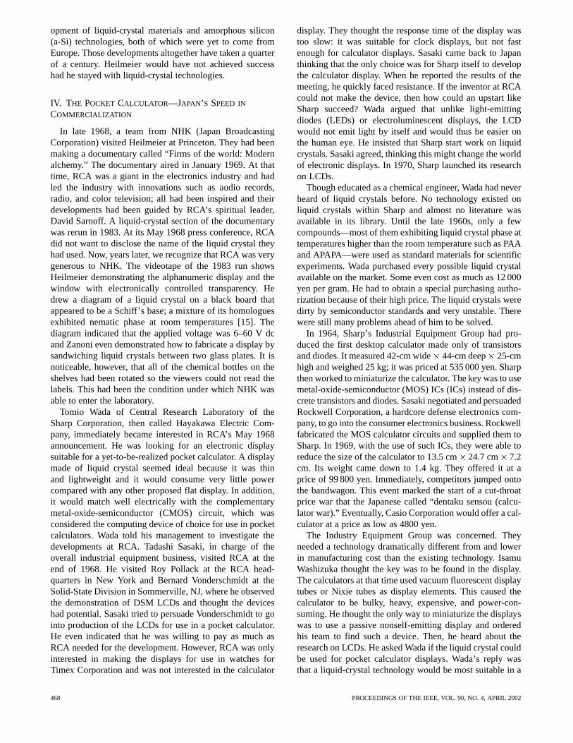
The key was to find a liquid crystal that would operateat room temperature and exhibit a high contrast display.Wada and his team mixed over 3000 kinds of liquid crystalsand synthesized over 500 mixtures. The objective was tosimulate the liquid-crystal mixture that Heilmeier had usedin the RCA press release. The work was time consuming andtedious. They finally arrived at a mixture of Schiff’s bases,consisting of n-(4-methoxybenzyliden)-4-n-butylaniline(MBBA), n-(4-ethoxybenzyliden)-4-n-butylaniline (EBBA),and n-(4-butoxybenzyliden)-4-n-butylaniline (BBBA) (seeFig. 12) [18]. It was of nematic type and exhibited nematicphase in the temperature range from -20 to 63C. It hadan n-type, a high , and a low viscosity. In the DSM, itworked in the temperature range from 0 to 40C. Wada’steam found that the addition of a small amount of impuritywas required to induce ionic currents and thus to aide theformation of space charges. The quantity of impurity wasdetermined by taking into account his findings: increasingthe impurity reduced the lowest operating temperature, theimpurity made a current distribution uniform leading to a
Fig. 12. MBBA and its homologues used in the pocket calculator.
uniform display, and further increasing the impurity raisedthe ionic current and reduced the life of the display. Hefound that tetra butyl ammonium salt XCOON C Hwas chemically stable and useful for the improvement ofelectrooptical properties. Wada found that as he purified theliquid crystals to a higher degree, he needed to add moreimpurities to create ionic currents.
In addition to the investigation of the material itself, theteam needed to investigate which driving method, ac or dc,was superior. The dc field caused the generation of bubblesin the mixture and degraded the material rather quickly. Theac field caused a difficulty in operation at low temperaturesand required a complicated electronic circuit. They eventu-ally settled on the ac field. Another problem was the require-ment for a transparent yet electrically conductive plate. Wadawent to Shunsuke Kobayashi of Tokyo University of Agricul-ture and Technology and found that the Ministry of Interna-tional Trade and Industry (MITI) Laboratory in Osaka hadbeen working on indium tin oxide (ITO). Sharp sent an en-gineer to the laboratory to learn the ITO technique. Back atSharp, he could replicate the ITO film with the use of elec-tron beams. Then, they were told that the research at the MITILaboratory was being done to aide small size companies. Touse the results of the research, large companies such as Sharphad to receive special permission. Wada persuaded MITI togrant permission based on the prospect that LCDs would be-come the key device for the future of Japanese industriesand that the mass production of LCDs would require an in-frastructure of many small companies, which would benefitfrom the creation of a new liquid-crystal industry. They also
KAWAMOTO: THE HISTORY OF LIQUID-CRYSTAL DISPLAYS 469
had to solve a host of other problems such as developing thephotolithography technology for forming the required con-ductive pattern on a glass substrate, holding the two glassplates a few micrometers apart and at a perfectly constantdistance, and prealigning liquid-crystal molecules in one di-rection.
The other problem was computing and driving circuits.Everybody agreed that CMOS was the right solution. Its elec-trical power consumption is low compared with bipolar andMOS circuits, thus, it is ideal for use with batteries, where theelectrical energy supply is limited. The operating voltage forCMOS circuits was a good match with LCDs. For the idea ofCMOS circuits, we go back to Paul Weimer of RCA Labora-tories in 1962 [19].2 RCA and Fairchild were involved in thecommercialization of the CMOS circuits, but only interestedin military applications. Sharp needed to find a company thatwould supply them with the CMOS circuits for use in “con-sumer-use” electronic calculators.
Just at that time, Yasoji Suzuki of the Toshiba Corporationwas working on such CMOS circuits. He had developed a“clocked” CMOS circuit [20]. When a clock pulse was sup-plied to the clocked CMOS inverter, the circuit acted as aconventional inverter. When no clock pulse was supplied,the circuit stored a charge on the output capacitors. Thus theoverall power dissipated by the circuit was reduced substan-tially. The power consumption for conventional p-MOS cir-cuits designed for a calculator was from 400 to 500 mW; thepower consumption was reduced to less than 2 mW with theuse of clocked CMOS circuits. He constructed a mockup anddemonstrated it to Sharp engineers, who were sufficiently in-trigued to ask to borrow the mockup for test purposes. Even-tually, he supplied the clocked CMOS LSIs to the Sharp Cor-poration. Just before April 1973, Sharp completed the devel-opment of the pocket calculator and constructed a productionline for manufacturing the new product.
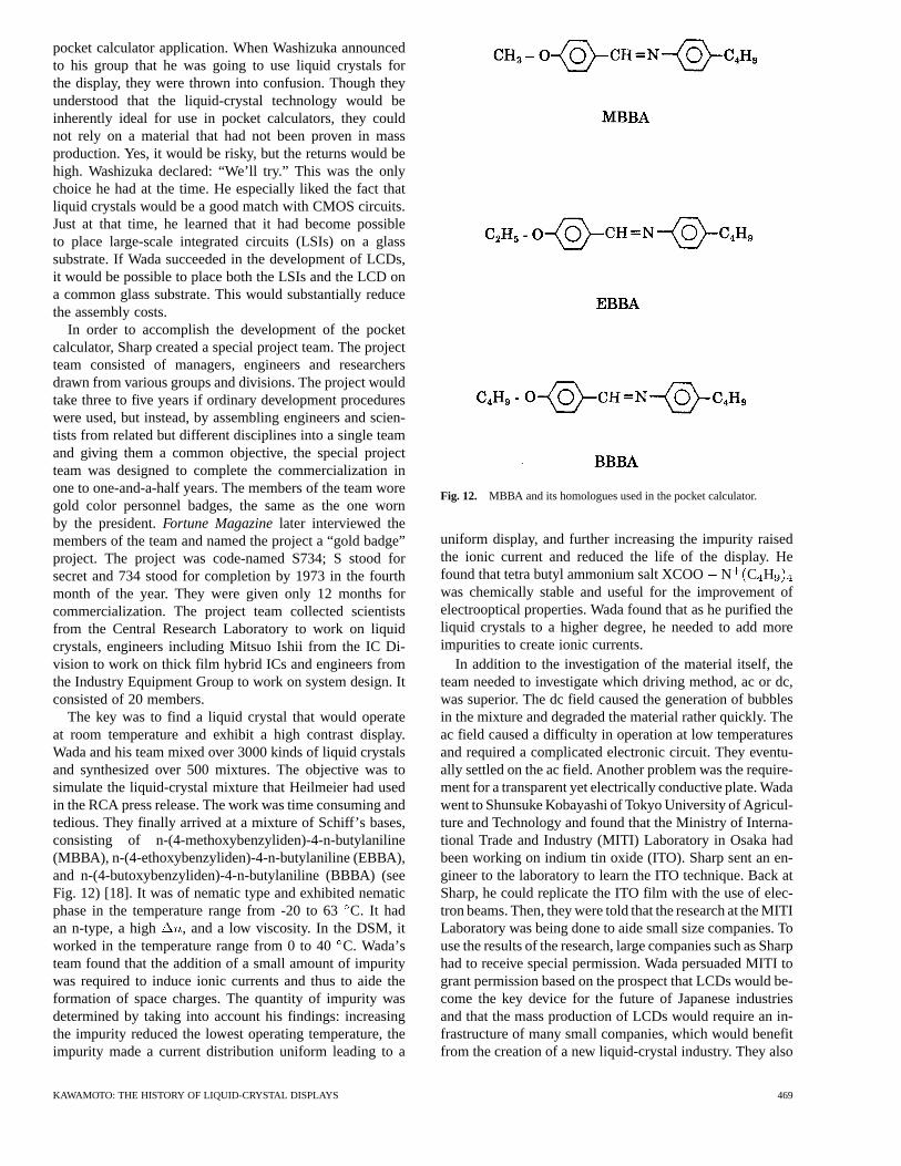
On May 15, 1973, Sharp announced [21] and subsequentlyintroduced the Elsi Mate EL-805 pocket calculator, com-prised of an LCD and five ICs placed on a common glasssubstrate (see Fig. 13) [22]. The calculator was revolutionarybecause it was only 2.1-cm thick, a reduction by a factor of12 from other electronic calculators available at that time. Itweighed 200 g, a reduction by a factor of 125. It could beslipped into a shirt pocket. Its power consumption was onlyone 1/9000 of existing calculators, so it could be operatedfor 100 h with a single AA-size dry battery. Wada recallsthat, on the day before they shipped the first pocket calcu-lator, Atsushi Asada, then General Manager of the Indus-trial Equipment Division, cornered him and asked whetherthe pocket calculator was really reliable enough to be placedin the market place. Wada knew that the MBBA mixture wasunstable and had, thus, sealed the cell extremely tightly. Hedid not have any choice other than saying, “It should be OK.”The calculator was an immediate hit in the market place and
2When he saw the pocket calculator at Sharp’s museum, James Tietjen,then the President of David Sarnoff Research Center, formerly RCA Labora-tories, grumbled that two technologies both key to the realization of pocketcalculators—LCDs and CMOS circuits—had started at RCA Laboratoriesand ended up at Sharp Corporation.
Fig. 13. The first liquid-crystal pocket calculator, which usedDSM. Courtesy of Sharp Corporation.
was the first commercially successful product to use an LCD.One such calculator, now 28 years old, has been found stilloperational.
The ultimate goal for developing LCDs was to accomplisha wall-hanging television. When he had invented the LCD,Heilmeier had thought that a wall-hanging television wouldbe just around the corner. When I asked Wada if he had thesame thought when he succeeded in the pocket-calculatordisplay, his reflection was that the time response of DSMwas very slow. Television needed a fast response and mul-tiplexing. He did not think making a television using DSMtechnology would be possible for a long time. To createa television display, one had to have yet-to-be-discoveredmodes of operation, such as TN mode and AM drivingand yet-to-be-synthesized materials such as phenyl cyclo-hexanes. Wada never imagined that LCDs would create anentire industry.
V. TWISTED–NEMATIC MODE—NEW MODE OFOPERATION
DISCOVEREDALMOST SIMULTANEOUSLY IN SWITZERLAND
AND AMERICA
The pocket calculator that Sharp introduced in 1973 wasa great success; calculators, which had been targeted at thebusiness market, were now being used in classrooms andhomes. The pocket calculator was even used in unforeseenways. One day, a Sharp’s Sales Division representative re-ceived a telephone call from the Tohoku district in northernJapan. The caller said that a calculator had stopped working.It was discovered that the customer had been using it in anoutdoor lumberyard in subzero temperatures. Wada knewthat the pocket calculator did not work at subzero tempera-tures; it was operational only in the range of 0–40C. Thedesigners had never expected it would be used outdoors,but because the calculator was portable, its area of use hadchanged. The Sales Division now demanded a calculatorthat would work both indoors and outdoors. Asada orderedmanufacturing of the calculator to be stopped. The engineersobjected, saying that the use at subzero temperatures waslimited to winter times in northern areas and in most places
470 PROCEEDINGS OF THE IEEE, VOL. 90, NO. 4, APRIL 2002
(a) (b) (c)
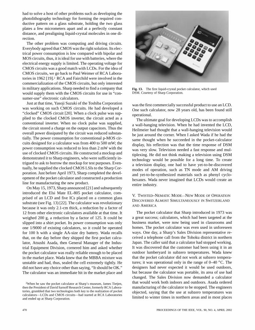
Fig. 14. Nematic molecules’ parallel alignment along grooves. (a) In free space, molecules arealigned in a loosely ordered fashion with their long axes in parallel. (b) When flowing on a finelygrooved surface. (c) Molecules are lined up parallel along the grooves.
in Japan, customers could make full use of the existingproduct. Besides, the calculator was selling like hot cakes.Why not concentrate on selling what they had in theirhands? Nevertheless, Asada insisted they develop a newcalculator that would work not only at subzero temperatures,but be thinner than the first model and even be capable ofdisplaying complicated Japanese Kanji characters. Afterthat, the engineers started referring to Asada as “the devil.”
When the Sharp engineers started the development of thenext generation pocket calculator, negative liquid crystalsthat worked at subzero temperatures in the DSM did notexist. Besides, the Schiff’s-base liquid crystals were easilyhydrolyzed, which caused them to deteriorate. Though thedrain on the batteries for the pocket calculator using the DSMwas much slower than that for Nixie tube calculators, theionic currents required for the operation of the DSM causedthe batteries to drain faster than the very small currents ofthe TN mode. Since the time response of the MBBA in theDSM at near-zero temperature was very slow, the numeralson the screen appeared and disappeared very slowly. Somecalled it an “Obake” or a ghost because ghosts in Japan arebelieved to appear and disappear in slow motion. In order tocreate a reliable calculator that would work at subzero tem-peratures and exhibit a fast response, the engineers had towait for the developments taking place on the other side ofthe globe: the discovery of TN mode and the synthesis of newp-type liquid crystals which this field-effect mode required:“cyanobiphenyls” (see Section VI).
A. Discovery of Twisted-Nematic Mode by Schadt andHelfrich
Wolfgang Helfrich joined RCA Laboratories, Princeton,NJ, in 1966, and then took a leave of absence in Germanyfor one year. He came back to RCA in October 1967and was assigned to Heilmeier’s emerging Liquid CrystalGroup. He found much data had been accumulated on liquidcrystals, but no physical explanation had been offered forthe data. He started modeling LCDs to help understand thephysics of the DSM. He reasoned that the Williams domainwas current-induced shear torque and that the DSM wasperturbation caused by further driving the Williams domain[13]. In the course of the analyses, an idea came to his mindfor a new method of driving liquid crystals—to TN liquid
crystals of p-type. Helfrich recalls that when, in the summerof 1969, he went up to Heilmeier and explained the newidea, Heilmeier showed little interest because the new moderequired two polarizers. At the time, liquid-crystal workwas winding down at RCA. Frustrated by their interactionswith the product division, the engineers and chemists in theliquid-crystal team started to drift away. Zanoni went toOptel, where he continued to develop liquid-crystal tech-nology and displays. Later he was joined by Goldmacherwho had made an interim stop at St. Regis Paper. Heilmeierleft in 1970 to become a White House Fellow. Castellano,Chan Oh, and Mike McCaffrey also departed to work onLCDs elsewhere.
Helfrich also left RCA and in early October 1970 joinedHoffmann–La Roche in Basel, Switzerland, to work withMartin Schadt. Helfrich suggested that Schadt, rather thanusing the DSM, try a totally new mechanism of operation.Schadt agreed and devised an experimental setup. In a fewweeks, they found a new workable mechanism: TN mode. OnDecember 4, 1970, they filed a patent with the Patent Officein Switzerland [23]. A mere four days later, they submittedthe now historic paper “Voltage-dependent optical activity ofa twisted nematic liquid crystal” toApplied Physics Letters[24]. They said that, up to that point, three electrooptical ef-fects had been known: 1) domain formation; 2) dynamic scat-tering; and 3) guest-host interaction. They reported the dis-covery of a fourth electrooptical effect. It involved realign-ment of liquid-crystal molecules by dielectric torques. Thenew effect required the orientation pattern to be twisted inthe fieldless state.
As shown in Fig. 14(a), nematic liquid crystals, typically30 Å in length, in natural states are arranged in a loosely or-dered fashion with their long axes in parallel arrangement. Ifgrooves are carved on the surface as shown in Fig. 14(b) and(c), the liquid crystals lie on the surface and line up in parallelwith the direction of the grooves [25], [26]. Let us considerthe case where the liquid crystals are sandwiched betweenan upper plate and a lower plate and the plates are groovedin directions “a” and “b,” which are orthogonal to each otheras shown in Fig. 15. The molecules along the upper platealign in direction “a” and those along the lower plate in di-rection “b.” This forces the liquid crystals into a 90he-lical twist [27]. An LCD may be structured as sketched in
KAWAMOTO: THE HISTORY OF LIQUID-CRYSTAL DISPLAYS 471
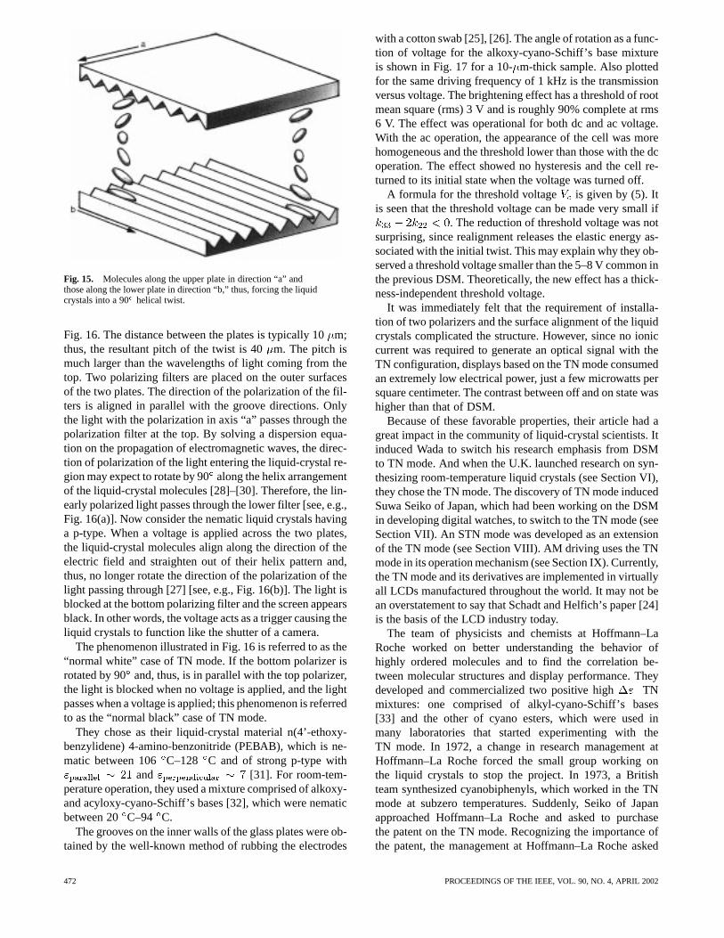
Fig. 15. Molecules along the upper plate in direction “a” andthose along the lower plate in direction “b,” thus, forcing the liquidcrystals into a 90 helical twist.
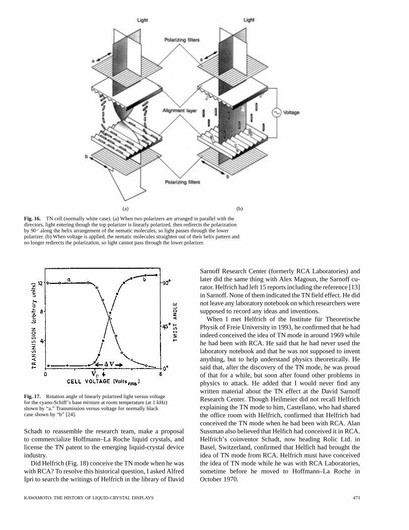
Fig. 16. The distance between the plates is typically 10m;thus, the resultant pitch of the twist is 40m. The pitch ismuch larger than the wavelengths of light coming from thetop. Two polarizing filters are placed on the outer surfacesof the two plates. The direction of the polarization of the fil-ters is aligned in parallel with the groove directions. Onlythe light with the polarization in axis “a” passes through thepolarization filter at the top. By solving a dispersion equa-tion on the propagation of electromagnetic waves, the direc-tion of polarization of the light entering the liquid-crystal re-gion may expect to rotate by 90along the helix arrangementof the liquid-crystal molecules [28]–[30]. Therefore, the lin-early polarized light passes through the lower filter [see, e.g.,Fig. 16(a)]. Now consider the nematic liquid crystals havinga p-type. When a voltage is applied across the two plates,the liquid-crystal molecules align along the direction of theelectric field and straighten out of their helix pattern and,thus, no longer rotate the direction of the polarization of thelight passing through [27] [see, e.g., Fig. 16(b)]. The light isblocked at the bottom polarizing filter and the screen appearsblack. In other words, the voltage acts as a trigger causing theliquid crystals to function like the shutter of a camera.
The phenomenon illustrated in Fig. 16 is referred to as the“normal white” case of TN mode. If the bottom polarizer isrotated by 90 and, thus, is in parallel with the top polarizer,the light is blocked when no voltage is applied, and the lightpasses when a voltage is applied; this phenomenon is referredto as the “normal black” case of TN mode.
They chose as their liquid-crystal material n(4’-ethoxy-benzylidene) 4-amino-benzonitride (PEBAB), which is ne-matic between 106C–128 C and of strong p-type with
and [31]. For room-tem-perature operation, they used a mixture comprised of alkoxy-and acyloxy-cyano-Schiff’s bases [32], which were nematicbetween 20 C–94 C.
The grooves on the inner walls of the glass plates were ob-tained by the well-known method of rubbing the electrodes
with a cotton swab [25], [26]. The angle of rotation as a func-tion of voltage for the alkoxy-cyano-Schiff’s base mixtureis shown in Fig. 17 for a 10-m-thick sample. Also plottedfor the same driving frequency of 1 kHz is the transmissionversus voltage. The brightening effect has a threshold of rootmean square (rms) 3 V and is roughly 90% complete at rms6 V. The effect was operational for both dc and ac voltage.With the ac operation, the appearance of the cell was morehomogeneous and the threshold lower than those with the dcoperation. The effect showed no hysteresis and the cell re-turned to its initial state when the voltage was turned off.
A formula for the threshold voltage is given by (5). Itis seen that the threshold voltage can be made very small if
. The reduction of threshold voltage was notsurprising, since realignment releases the elastic energy as-sociated with the initial twist. This may explain why they ob-served a threshold voltage smaller than the 5–8 V common inthe previous DSM. Theoretically, the new effect has a thick-ness-independent threshold voltage.
It was immediately felt that the requirement of installa-tion of two polarizers and the surface alignment of the liquidcrystals complicated the structure. However, since no ioniccurrent was required to generate an optical signal with theTN configuration, displays based on the TN mode consumedan extremely low electrical power, just a few microwatts persquare centimeter. The contrast between off and on state washigher than that of DSM.
Because of these favorable properties, their article had agreat impact in the community of liquid-crystal scientists. Itinduced Wada to switch his research emphasis from DSMto TN mode. And when the U.K. launched research on syn-thesizing room-temperature liquid crystals (see Section VI),they chose the TN mode. The discovery of TN mode inducedSuwa Seiko of Japan, which had been working on the DSMin developing digital watches, to switch to the TN mode (seeSection VII). An STN mode was developed as an extensionof the TN mode (see Section VIII). AM driving uses the TNmode in its operation mechanism (see Section IX). Currently,the TN mode and its derivatives are implemented in virtuallyall LCDs manufactured throughout the world. It may not bean overstatement to say that Schadt and Helfich’s paper [24]is the basis of the LCD industry today.
The team of physicists and chemists at Hoffmann–LaRoche worked on better understanding the behavior ofhighly ordered molecules and to find the correlation be-tween molecular structures and display performance. Theydeveloped and commercialized two positive high TNmixtures: one comprised of alkyl-cyano-Schiff’s bases[33] and the other of cyano esters, which were used inmany laboratories that started experimenting with theTN mode. In 1972, a change in research management atHoffmann–La Roche forced the small group working onthe liquid crystals to stop the project. In 1973, a Britishteam synthesized cyanobiphenyls, which worked in the TNmode at subzero temperatures. Suddenly, Seiko of Japanapproached Hoffmann–La Roche and asked to purchasethe patent on the TN mode. Recognizing the importance ofthe patent, the management at Hoffmann–La Roche asked
472 PROCEEDINGS OF THE IEEE, VOL. 90, NO. 4, APRIL 2002
(a) (b)
Fig. 16. TN cell (normally white case). (a) When two polarizers are arranged in parallel with thedirectors, light entering though the top polarizer is linearly polarized, then redirects the polarizationby 90 along the helix arrangement of the nematic molecules, so light passes through the lowerpolarizer. (b) When voltage is applied, the nematic molecules straighten out of their helix pattern andno longer redirects the polarization, so light cannot pass through the lower polarizer.
Fig. 17. Rotation angle of linearly polarized light versus voltagefor the cyano-Schiff’s base mixture at room temperature (at 1 kHz)shown by “a.” Transmission versus voltage for normally blackcase shown by “b” [24].
Schadt to reassemble the research team, make a proposalto commercialize Hoffmann–La Roche liquid crystals, andlicense the TN patent to the emerging liquid-crystal deviceindustry.
Did Helfrich (Fig. 18) conceive the TN mode when he waswith RCA? To resolve this historical question, I asked AlfredIpri to search the writings of Helfrich in the library of David
Sarnoff Research Center (formerly RCA Laboratories) andlater did the same thing with Alex Magoun, the Sarnoff cu-rator. Helfrich had left 15 reports including the reference [13]in Sarnoff. None of them indicated the TN field effect. He didnot leave any laboratory notebook on which researchers weresupposed to record any ideas and inventions.
When I met Helfrich of the Institute für TheoretischePhysik of Freie University in 1993, he confirmed that he hadindeed conceived the idea of TN mode in around 1969 whilehe had been with RCA. He said that he had never used thelaboratory notebook and that he was not supposed to inventanything, but to help understand physics theoretically. Hesaid that, after the discovery of the TN mode, he was proudof that for a while, but soon after found other problems inphysics to attack. He added that I would never find anywritten material about the TN effect at the David SarnoffResearch Center. Though Heilmeier did not recall Helfrichexplaining the TN mode to him, Castellano, who had sharedthe office room with Helfrich, confirmed that Helfrich hadconceived the TN mode when he had been with RCA. AlanSussman also believed that Helfich had conceived it in RCA.Helfrich’s coinventor Schadt, now heading Rolic Ltd. inBasel, Switzerland, confirmed that Helfich had brought theidea of TN mode from RCA. Helfrich must have conceivedthe idea of TN mode while he was with RCA Laboratories,sometime before he moved to Hoffmann–La Roche inOctober 1970.
KAWAMOTO: THE HISTORY OF LIQUID-CRYSTAL DISPLAYS 473
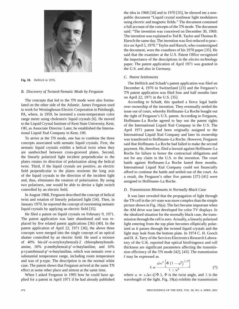
Fig. 18. Helfrich in 1976.
B. Discovery of Twisted-Nematic Mode by Fergason
The concepts that led to the TN mode were also formu-lated on the other side of the Atlantic. James Fergason usedto work for Westinghouse Electric Corporation in Pittsburgh,PA, where, in 1959, he invented a room-temperature colorrange meter using cholesteric liquid crystals [6]. He movedto the Liquid Crystal Institute of Kent State University, Kent,OH, as Associate Director. Later, he established the Interna-tional Liquid Xtal Company in Kent, OH.
To arrive at the TN mode, one has to combine the threeconcepts associated with nematic liquid crystals. First, thenematic liquid crystals exhibit a helical twist when theyare sandwiched between cross-grooved plates. Second,the linearly polarized light incident perpendicular to theplates rotates its direction of polarization along the helicaltwist. Third, if the liquid crystals are positive, an electricfield perpendicular to the plates reorients the long axisof the liquid crystals to the direction of the incident lightand, thus, eliminates the rotation of polarization. By usingtwo polarizers, one would be able to devise a light switchcontrolled by an electric field.
In August 1968, Fergason described the concept of helicaltwist and rotation of linearly polarized light [34]. Then, inJanuary 1970, he reported the concept of reorienting nematicliquid crystals by applying an electric field [35].
He filed a patent on liquid crystals on February 9, 1971.The patent application was later abandoned and was re-placed by five related patent applications [36]–[40]. In thepatent application of April 22, 1971 [36], the above threeconcepts were merged into the single concept of an opticalshutter controlled by an electric field. He used a mixtureof 40% bis-(4’-n-octyloxybenzal)-2 chlorophenylenedi-amine, 50% p-methybenzal-p’-n-butylaniline, and 10%p-cyanobenzal-p’-n-butylaniline, which was nematic over asubstantial temperature range, including room temperatureand was of p-type. The description is on the normal whitecase. The patent shows that Fergason arrived at the same TNeffect at some other place and almost at the same time.
When I asked Fergason in 1995 how he could have ap-plied for a patent in April 1971 if he had already published
the idea in 1968 [34] and in 1970 [35], he showed me a non-public document “Liquid crystal nonlinear light modulatorsusing electric and magnetic fields.” The document containeda full account of the concepts of the TN mode. The documentsaid: “The invention was conceived on December 30, 1969.The invention was explained to Ted R. Taylor and Thomas B.Harsch the same day. The invention was first reduced to prac-tice on April 5, 1970.” Taylor and Harsch, who countersignedthe document, were the coauthors of his 1970 paper [35]. Hesaid that the examiner at the U.S. Patent Office recognizedthe importance of the descriptions in theelectro technologypaper. The patent application of April 1971 was granted inthe U.S. and also in Germany.
C. Patent Settlements
The Helfrich and Schadt’s patent application was filed onDecember 4, 1970 in Switzerland [23] and the Fergason’sTN patent application was filed four and half months lateron April 22, 1971 in the U.S. [35].
According to Schadt, this sparked a fierce legal battleover ownership of the invention. They eventually settled theissue out of court, whereby Hoffmann–La Roche bought outthe right of Fergason’s U.S. patent. According to Fergason,Hoffmann–La Roche agreed to buy out the patent rightsof the International Liquid Xtal Company in the U.S. TheApril 1971 patent had been originally assigned to theInternational Liquid Xtal Company and later its ownershipwas transferred to Hoffmann–La Roche. However, Fergasonsaid that Hoffmann–La Roche had failed to make the secondpayment. He, therefore, filed a lawsuit against Hoffmann–LaRoche for failure to honor the contractual obligations andnot for any claim in the U.S. to the invention. The courtbattle against Hoffmann–La Roche lasted three months.International Liquid Xtal Company could not financiallyafford to continue the battle and settled out of the court. Asa result, the Fergason’s other five patents [37]–[41] wereassigned to Hoffmann–La Roche.
D. Transmission Minimums in Normally Black Case
It was later revealed that the propagation of light throughthe TN cell in theOFFstate was more complex than the simplepicture shown in Fig. 16(a). The fact became important whenthe AM drive was later developed for color TV displays. Inthe idealized situation for the normally black case, the trans-mission through the cell is zero. Actually, a linearly polarizedlight entering from the top plate becomes elliptically polar-ized as it passes through the twisted liquid crystals and thelight may leak from the bottom plate. In 1974 C. H. Goochand H. A. Tarry of the Services Electronics Research Labora-tory of the U.K. reported that optical birefringence and cellthickness are significant parameters affecting the transmis-sion efficiency of the TN mode [42], [43]. The transmission
may be expressed as
(7)
where , is the twist angle, and is thewavelength of the light. Fig. 19(a) exhibits the transmission
474 PROCEEDINGS OF THE IEEE, VOL. 90, NO. 4, APRIL 2002
(a)
(b)
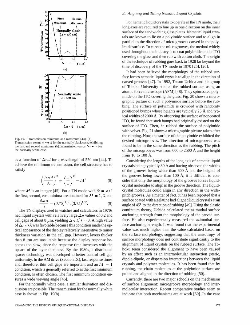
Fig. 19. Transmission minimum and maximum [44]. (a)Transmission versus�n� �d for the normally black case, exhibitingthe first and second minimum. (b)Transmission versus�n � �d forthe normally white case.
as a function of for a wavelength of 550 nm [44]. Toachieve the minimum transmission, the cell structure has tosatisfy
(8)
where is an integer [45]. For a TN mode with 2the first, second, etc., minima are obtained for etc.
(9)
The TN displays used in watches and calculators in 1970shad liquid crystals with relatively large values of 0.2 andcell gaps of about 8m, yielding 3. A high valueof was favorable because this condition made the op-tical appearance of the display relatively insensitive to minorthickness variation in the cell gap. However, layers thickerthan 8 m are unsuitable because the display response be-comes too slow, since the response time increases with thesquare of the layer thickness. By the 1980s, a distributedspacer technology was developed to better control cell gapuniformity. In the AM drive (Section IX), fast response timesand, therefore, thin cell gaps are important and ancondition, which is generally referred to as the first minimumcondition, is often chosen. The first minimum condition en-sures a wide viewing angle [46].
For the normally white case, a similar derivation and dis-cussion are possible. The transmission for the normally whitecase is shown in Fig. 19(b).
E. Aligning and Tilting Nematic Liquid Crystals
For nematic liquid crystals to operate in the TN mode, theirlong axes are required to line up in one direction on the innersurface of the sandwiching glass plates. Nematic liquid crys-tals are known to lie on a polyimide surface and to align inparallel to the direction of microgrooves carved in the poly-imide surface. To carve the microgrooves, the method widelyused throughout the industry is to coat polyimide on the ITOcovering the glass and then rub with cotton cloth. The originof the technique of rubbing goes back to 1928 far beyond thetime of discovery of the TN mode in 1970 [25], [26].
It had been believed the morphology of the rubbed sur-face forces nematic liquid crystals to align in the direction ofcarved grooves [47]. In 1992, Tatsuo Uchida and his groupof Tohoku University studied the rubbed surface using anatomic force microscope (AFM) [48]. They spincoated poly-imide on the ITO covering the glass. Fig. 20 shows a micro-graphic picture of such a polyimide surface before the rub-bing. The surface of polyimide is crowded with randomlypositioned bumps whose heights are typically 25 Å and typ-ical widths of 2000 Å. By observing the surface of noncoatedITO, he found that such bumps had originally existed on thesurface of ITO. Then, he rubbed the surface of polyimidewith velvet. Fig. 21 shows a micrographic picture taken afterthe rubbing. Now, the surface of the polyimide exhibited thedesired microgrooves. The direction of microgrooves wasfound to be in the same direction as the rubbing. The pitchof the microgrooves was from 600 to 2500 Å and the heightfrom 10 to 100 Å.
Considering the lengths of the long axis of nematic liquidcrystals being typically 30 Å and having observed the widthsof the grooves being wider than 600 Å and the heights ofthe grooves being lower than 100 Å, it is difficult to con-sider that only the morphology of the grooves forces liquid-crystal molecules to align in the groove direction. The liquid-crystal molecules could align in any direction in the wide-pitch grooves. As a matter of fact, it has been reported that asurface coated with a gelatine had aligned liquid crystals at anangle of 45 to the direction of rubbing [49]. Using the elasticcontinuum theory, Uchida calculated the azimuthal surfaceanchoring strength from the morphology of the carved sur-face. He also experimentally measured the azimuthal sur-face anchoring strength. It was found that the experimentalvalue was much higher than the value calculated based onthe surface morphology, suggesting that the anisotropy ofsurface morphology does not contribute significantly to thealignment of liquid crystals on the rubbed surface. The To-hoku team considered the alignment to have been causedby an effect such as an intermolecular interaction (steric,dipole-dipole, or dispersion interaction) between the liquidcrystals and polymer molecules. It has been found that byrubbing, the chain molecules at the polyimide surface arepulled and aligned in the direction of rubbing [50].
Currently, there are two major schools on the mechanismof surface alignment: microgroove morphology and inter-molecular interaction. Recent comparative studies seem toindicate that both mechanisms are at work [50]. In the case
KAWAMOTO: THE HISTORY OF LIQUID-CRYSTAL DISPLAYS 475
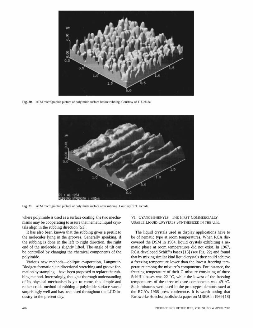
Fig. 20. ATM micrographic picture of polyimide surface before rubbing. Courtesy of T. Uchida.
Fig. 21. ATM micrographic picture of polyimide surface after rubbing. Courtesy of T. Uchida.
where polyimide is used as a surface coating, the two mecha-nisms may be cooperating to assure that nematic liquid crys-tals align in the rubbing direction [51].
It has also been known that the rubbing gives a pretilt tothe molecules lying in the grooves. Generally speaking, ifthe rubbing is done in the left to right direction, the rightend of the molecule is slightly lifted. The angle of tilt canbe controlled by changing the chemical components of thepolyimide.
Various new methods—oblique evaporation, Langmuir-Blodgett formation, unidirectional stretching and groove for-mation by stamping—have been proposed to replace the rub-bing method. Interestingly, though a thorough understandingof its physical mechanism is yet to come, this simple andrather crude method of rubbing a polyimide surface workssurprisingly well and has been used throughout the LCD in-dustry to the present day.
VI. CYANOBIPHENYLS—THE FIRST COMMERCIALLY
USABLE LIQUID CRYSTALS SYNTHESIZED IN THE U.K.
The liquid crystals used in display applications have tobe of nematic type at room temperatures. When RCA dis-covered the DSM in 1964, liquid crystals exhibiting a ne-matic phase at room temperatures did not exist. In 1967,RCA developed Schiff’s bases [15] (see Fig. 22) and foundthat by mixing similar kind liquid crystals they could achievea freezing temperature lower than the lowest freezing tem-perature among the mixture’s components. For instance, thefreezing temperature of their G mixture consisting of threeSchiff’s bases was 22C, while the lowest of the freezingtemperatures of the three mixture components was 49C.Such mixtures were used in the prototypes demonstrated atthe RCA’s 1968 press conference. It is worth noting thatFarbwerke Hoechst published a paper on MBBA in 1969 [18]
476 PROCEEDINGS OF THE IEEE, VOL. 90, NO. 4, APRIL 2002
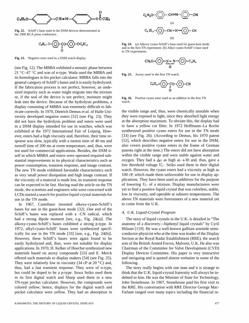
Fig. 22. Schiff’s base used in the DSM devices demonstrated atthe 1968 RCA press conference.
Fig. 23. Negative ester used in a DSM watch display.
(see Fig. 12). The MBBA exhibited a nematic phase between21 C–47 C and was of n-type. Wada used the MBBA andits homologues in his pocket calculator. MBBA falls into thegeneral category of Schiff’s bases and it is easily hydrolyzed.If the fabrication process is not perfect, however, an unde-sired impurity such as water might migrate into the mixtureor, if the seal of the device is not perfect, moisture mightleak into the device. Because of the hydrolysis problems, adisplay consisting of MBBA was extremely difficult to fab-ricate correctly. In 1970, Dietrich Demuset al.of Halle Uni-versity developed negative esters [52] (see Fig. 23). Theydid not have the hydrolysis problem and esters were usedin a DSM display intended for use in watches, which wasexhibited at the 1972 International Fair of Leipzig. How-ever, esters had a high viscosity and, therefore, their time re-sponse was slow, typically with a turnon time of 40 ms andturnoff time of 200 ms at room temperature, and, thus, werenot used for commercial applications. Besides, the DSM it-self in which MBBA and esters were operated required sub-stantial improvements in its physical characteristics such aspower consumption, transient response, and image contrast.The new TN mode exhibited favorable characteristics suchas very small power dissipation and high image contrast. Ifthe viscosity of a material is made low, its transient responsecan be expected to be fast. Having read the article on the TNmode, the scientists and engineers who were concerned withLCDs started a search for positive liquid-crystal materials foruse in the TN mode.
In 1967, Castellano invented alkoxy-cyano-Schiff’sbases for use in the guest-host mode [32]. One end of theSchiff’s bases was replaced with a -CN radical, whichhad a strong dipole moment [see, e.g., Fig. 24(a)]. Thealkoxy-cyano-Schiff’s bases exhibited a strong p-type. In1972, alkyl-cyano-Schiff’ bases were synthesized specif-ically for use in the TN mode [33] [see, e.g., Fig. 24(b)].However, these Schiff’s bases were again found to beeasily hydrolyzed and, thus, were not suitable for displayapplications. In 1970, H. Kelker of Hoechst synthesized newmaterials based on azoxy compounds [53] and E. Merckoffered such materials to display makers [54] (see Fig. 25).They were relatively low in viscosity (34 cP at 20C) and,thus, had a fast transient response. They were of n-type,but could be doped to be a p-type. Suwa Seiko used themin its first digital watch and Sharp used them in a newTN-type pocket calculator. However, the compounds werecolored yellow; hence, displays for the digital watch andpocket calculator were yellow. They had an absorption in
(a)
(b)
Fig. 24. (a) Alkoxy cyano-Schiff’s base used for guest-host modeand in the first TN experiment. (b) Alkyl cyano-Schiff’s base usedin TN experiments.
Fig. 25. Azoxy used in the first TN watch.
Fig. 26. Positive cyano ester used as an additive in the first TNwatch.
the visible range and, thus, were chemically unstable whenthey were exposed to light, since they absorbed light energyat the absorption maximum. To obviate this, the display hadto have a yellow cut filter. In 1972 Hoffmann–La Rochesynthesized positive cyano esters for use in the TN mode[33] (see Fig. 26). (According to Demus, his 1970 patent[52], which describes negative esters for use in the DSM,also covers positive cyano esters in the frame of Germanpatents right at the time.) The esters did not have absorptionwithin the visible range and were stable against water andoxygen. They had a as high as 30 and, thus, gave alow threshold voltage . Seiko used them in their digitalwatch. However, the cyano esters had a viscosity as high as100 cP, which made them unfavorable for use in display ap-plications. They have been used as additives for the purposeof lowering of a mixture. Display manufacturers wereyet to find a positive liquid crystal that was colorless, stable,low in viscosity, and operable at subzero temperatures. Theabove TN materials were forerunners of a new material yetto come from the U.K.
A. U.K. Liquid-Crystal Program
The story of liquid crystals in the U.K. is detailed in “Theanatomy of a discovery—biphenyl liquid crystals” by CyrilHilsum [119]. He was a well-known gallium arsenide semi-conductor physicist who at the time was leader of the DisplaySection at the Royal Radar Establishment (RRE), the searcharm of the British Armed Forces, Malvern, U.K. He also wasChairman of the Committee for Valve Development (CVD)Display Devices Committee. His paper is very instructiveand intriguing and is quoted almost verbatim in some of thefollowing.
The story really begins with one man and it is strange tothink that the U.K. liquid-crystal fraternity will always be in-debted to him. He was the Minister of State for Technology,John Stonehouse. In 1967, Stonehouse paid his first visit tothe RRE. His conversation with RRE Director George Mac-Farlane ranged over many topics including the financial re-
KAWAMOTO: THE HISTORY OF LIQUID-CRYSTAL DISPLAYS 477
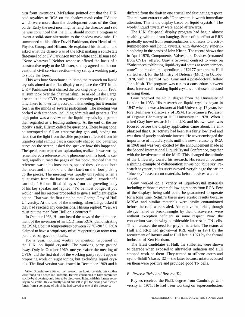
turn from inventions. McFarlane pointed out that the U.K.paid royalties to RCA on the shadow-mask color TV tubewhich were more than the development costs of the Con-corde. Early the next morning, he rang the director and saidhe was convinced that the U.K. should mount a program toinvent a solid-state alternative to the shadow mask tube. Hesummoned to his office David Parkinson, then Head of thePhysics Group, and Hilsum. He explained his situation andasked what the chance was of the RRE making a solid-stateflat-panel color TV. Parkinson turned white and Hilsum said:“None whatever.” Neither response offered the basis of aconstructive reply to the Minister, so they agreed on the con-ventional civil service reaction—they set up a working partyto study the topic.
This was how Stonehouse initiated the research on liquidcrystals aimed at the flat display to replace the CRT in theU.K.3 Parkinson first chaired the working party, but in 1968,Hilsum took over the chairmanship. He asked Leslie Large,a scientist in the CVD, to organize a meeting on liquid crys-tals. There is no written record of that meeting, but it remainsfresh in the minds of several participants. The meeting waspacked with attendees, including admirals and generals. Thehigh point was a review on the liquid crystals by a personthen regarded as a leading authority. At the end of the au-thority’s talk, Hilsum called for questions. There being none,he attempted to fill an embarrassing gap and, having no-ticed that the light from the slide projector reflected from hisliquid-crystal sample cast a curiously shaped and patternedcurve on the screen, asked the speaker how this happened.The speaker attempted an explanation, realized it was wrong,remembered a reference to the phenomenon in a book he car-ried, rapidly turned the pages of this book, decided that thereference was in his loose notes, opened these, dropped boththe notes and the book, and then knelt on the floor pickingup the pieces. The meeting was rapidly unraveling when aquiet voice from the back of the room said: “I wonder if Ican help.” Hilsum lifted his eyes from the groveling bodyof his key speaker and replied: “I’d be most obliged if youwould” and his rescuer proceeded to give a sufficient expla-nation. That was the first time he met George Gray of HullUniversity. At the end of the meeting, when Large asked ifthey had reached any conclusions, Hilsum replied: “Yes, wemust put the man from Hull on a contract.”
In October 1968, Hilsum heard the news of the announce-ment of the invention of an LCD from RCA, demonstratingthe DSM, albeit at temperatures between 77C–90 C. RCAclaimed to have a proprietary mixture operating at room tem-perature, but gave no details.
For a year, nothing worthy of mention happened inthe U.K. on liquid crystals. The working party groundaway. Only in October 1969, one year after the meeting ofCVDs, did the first draft of the working party report appear,proposing work on eight topics, but excluding liquid crys-tals. The final version was issued in December 1969 and it
3After Stonehouse initiated the research on liquid crystals, his clotheswere found on a beach in California. He was considered to have committedsuicide by drowning, only later to be discovered living with his former secre-tary in Australia. He eventually found himself in jail for having confiscatedfunds from a company of which he had served as one of the directors.
differed from the draft in one crucial and fascinating respect.The relevant extract reads “One system is worth immediateattention. This is the display based on liquid crystals.” Thewords “liquid crystals” were added afterwards.
The U.K. flat-panel display program had begun almoststealthily, with no drum-banging. Some of the effort at RREgradually moved from semiconductors and lasers to electro-luminescence and liquid crystals, with day-to-day supervi-sion being in the hands of John Kirton. The record shows thatin April 1970, Components, Valves, and Devices (renamedfrom CVDs) offered Gray a two-year contract to work on“Substances exhibiting liquid-crystal states at room temper-ature” at a maximum expenditure of £2177 per annum. Hullstarted work for the Ministry of Defence (MoD) in October1970, with a team of two: Gray and a post-doctoral fellowJohn Nash. The program was run as a consortium betweenthose interested in making liquid crystals and those interestedin using them.
Gray received the Ph.D. degree from the University ofLondon in 1953. His research on liquid crystals began in1947 when he was a lecturer at Hull University, 17 years be-fore Heilmeier’s discovery of DSM. He became a Professorof Organic Chemistry at Hull University in 1978. When Iasked Gray how research in the U.K. and his own work wasfocused before the display application came about, he em-phasized that U.K. activity had been at a fairly low level andwas then of purely academic interest. He never envisaged theimportance of liquid crystals until the news release by RCAin 1968 and was very excited by the announcement made atthe Second International Liquid Crystal Conference, togetherwith the involvement of the MoD. This changed the attitudeof the University toward his research. His research becamea shining example of collaboration; it was not “blue sky” re-search anymore, but its success owed everything to the earlier“blue sky” research on materials, before devices were con-ceived.
Gray worked on a variety of liquid-crystal materialsincluding carbonate esters following reports from RCA. Fewof the displays being sold could be guaranteed to operatefor a long time. Schiff’s bases gave erratic results becauseMBBA and similar materials were easily contaminatedbefore the cells were sealed. Alternative materials, thoughalways hailed as breakthroughs by their discoverers, werewithout exception deficient in some respect. Now, theconsortium was showing considerable interest in TN cells.This increased the need for p-type materials. The teams atHull and RRE had grown—at RRE early in 1971 by therecruitment of Raynes and at Hull late in 1971 by the formalinclusion of Ken Harrison.
The latest candidates at Hull, the stilbenes, were shownto degrade when exposed to ultraviolet radiation and Hullstopped work on them. They turned to stilbene esters andcyano-Schiff’s bases [32]—the latter because mixtures basedon them were positive and provided good TN cells.
B. Reverse Twist and Reverse Tilt
Raynes received the Ph.D. degree from Cambridge Uni-versity in 1971. He had been working on superconductors
478 PROCEEDINGS OF THE IEEE, VOL. 90, NO. 4, APRIL 2002
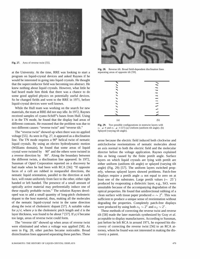
Fig. 27. Area of reverse twist [55].
at the University. At the time, RRE was looking to start aprogram on liquid-crystal devices and asked Raynes if hewould be interested in going into liquid crystals. He thoughtthat the superconductor field was becoming too abstract. Heknew nothing about liquid crystals. However, what little hehad heard made him think that there was a chance to dosome good applied physics on potentially useful devices.So he changed fields and went to the RRE in 1971, beforeliquid-crystal devices were well known.
While the Hull team was working on the search for newmaterials, the team at RRE did not stay idle. In 1972, Raynesreceived samples of cyano-Schiff”s bases from Hull. Usingit in the TN mode, he found that the display had areas ofdifferent contrasts. He reasoned that the problem was due totwo different causes: “reverse twist” and “reverse tilt.”
The “reverse twist” showed up when there was no appliedvoltage [55]. As seen in Fig. 27, it appeared as a disclinationline. The TN mode requires a 90helical twist of nematicliquid crystals. By using an electro hydrodynamic motion(Williams domain), he found that some areas of liquidcrystal were twisted by 90 and the others were twisted ina reverse direction by 90 . Along the boundary betweenthe different twists, a disclination line appeared. In 1972,Sussman of Optel Corporation reported on a discovery hehad made when he had been with RCA [56]: “If oppositefaces of a cell are rubbed in nonparallel directions, thenematic liquid orientation, parallel to the direction at eachface, will rotate uniformly from face to the other, either righthanded or left handed. The presence of a small amount ofoptically active material may preferentially induce one ofthese equally probable twists.” The solution Raynes devel-oped was to add a small quantity of long-pitch cholestericdopant to the host material, thus, making all the moleculesof the nematic liquid-crystal twist in the same directionalong the twist of cholesteric dopant [57]. A suitable valuefor , where is the cholesteric pitch length andis thelayer thickness, was found to be about 7 [57]. If becametoo large, areas of reverse twist could form.
The “reverse tilt” showed up when areas of reverse twistwere eliminated and when a voltage was applied [58]. Asseen in Fig. 28, other patches became noticeable. Broaddisinclination lines appeared separating these patches. These
Fig. 28. Reverse tilt. Broad field-dependent disclination linesseparating areas of opposite tilt [59].
(a) (b)
Fig. 29. Two possible configurations in nontwist layers with� 6= 0 and� 6= 0 [57] (a) Uniform (uniform tilt angle). (b)Splayed (varying tilt angle).
arose because the electric field induced both clockwise andanticlockwise reorientations of nematic molecules aboutan axis normal to both the electric field and the moleculardirector before the voltage application. Raynes explainedthis as being caused by the finite pretilt angle. Surfacelayers on which liquid crystals are lying with pretilt areeither uniform (uniform tilt angle) or splayed (varying tiltangle) (Fig. 29) [57]. The uniform layers switched prop-erly, whereas splayed layers showed problems. Patch-freedisplays require a pretilt angle not equal to zero on atleast one of the substrates. Large pretilt values (25 )produced by evaporating a dielectric layer, e.g., SiO, wereunsuitable because of the accompanying degradation of theoptical properties. He found that unidirectional rubbing of aclean surface with tissue paper produced 2 . This wassufficient to produce a unique sense of reorientation withoutdegrading the properties. Completely patch-free displayswere produced by using both 2 and 2 .
These methods of correcting the reverse twist and reversetilt [58] made the later materials synthesized by Grayet al.acceptable to display manufacturers. According to Sussman,just before he left RCA in around 1971, he exposed his dis-covery of correcting the reverse twist [56] to an RCA at-torney, whom he found was not interested in making the dis-covery a patent.
KAWAMOTO: THE HISTORY OF LIQUID-CRYSTAL DISPLAYS 479
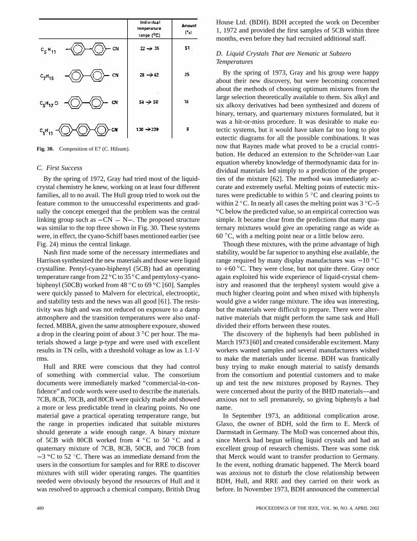
Fig. 30. Composition of E7 (C. Hilsum).
C. First Success
By the spring of 1972, Gray had tried most of the liquid-crystal chemistry he knew, working on at least four differentfamilies, all to no avail. The Hull group tried to work out thefeature common to the unsuccessful experiments and grad-ually the concept emerged that the problem was the centrallinking group such as CN N . The proposed structurewas similar to the top three shown in Fig. 30. These systemswere, in effect, the cyano-Schiff bases mentioned earlier (seeFig. 24) minus the central linkage.
Nash first made some of the necessary intermediates andHarrison synthesized the new materials and those were liquidcrystalline. Pentyl-cyano-biphenyl (5CB) had an operatingtemperature range from 22C to 35 C and pentyloxy-cyano-biphenyl (50CB) worked from 48C to 69 C [60]. Sampleswere quickly passed to Malvern for electrical, electrooptic,and stability tests and the news was all good [61]. The resis-tivity was high and was not reduced on exposure to a dampatmosphere and the transition temperatures were also unaf-fected. MBBA, given the same atmosphere exposure, showeda drop in the clearing point of about 3C per hour. The ma-terials showed a large p-type and were used with excellentresults in TN cells, with a threshold voltage as low as 1.1-Vrms.
Hull and RRE were conscious that they had controlof something with commercial value. The consortiumdocuments were immediately marked “commercial-in-con-fidence” and code words were used to describe the materials.7CB, 8CB, 70CB, and 80CB were quickly made and showeda more or less predictable trend in clearing points. No onematerial gave a practical operating temperature range, butthe range in properties indicated that suitable mixturesshould generate a wide enough range. A binary mixtureof 5CB with 80CB worked from 4 C to 50 C and aquaternary mixture of 7CB, 8CB, 50CB, and 70CB from
3 C to 52 C. There was an immediate demand from theusers in the consortium for samples and for RRE to discovermixtures with still wider operating ranges. The quantitiesneeded were obviously beyond the resources of Hull and itwas resolved to approach a chemical company, British Drug
House Ltd. (BDH). BDH accepted the work on December1, 1972 and provided the first samples of 5CB within threemonths, even before they had recruited additional staff.
D. Liquid Crystals That are Nematic at SubzeroTemperatures
By the spring of 1973, Gray and his group were happyabout their new discovery, but were becoming concernedabout the methods of choosing optimum mixtures from thelarge selection theoretically available to them. Six alkyl andsix alkoxy derivatives had been synthesized and dozens ofbinary, ternary, and quarternary mixtures formulated, but itwas a hit-or-miss procedure. It was desirable to make eu-tectic systems, but it would have taken far too long to ploteutectic diagrams for all the possible combinations. It wasnow that Raynes made what proved to be a crucial contri-bution. He deduced an extension to the Schröder-van Laarequation whereby knowledge of thermodynamic data for in-dividual materials led simply to a prediction of the proper-ties of the mixture [62]. The method was immediately ac-curate and extremely useful. Melting points of eutectic mix-tures were predictable to within 5C and clearing points towithin 2 C. In nearly all cases the melting point was 3C–5C below the predicted value, so an empirical correction was
simple. It became clear from the predictions that many qua-ternary mixtures would give an operating range as wide as60 C, with a melting point near or a little below zero.
Though these mixtures, with the prime advantage of highstability, would be far superior to anything else available, therange required by many display manufactures was10 Cto 60 C. They were close, but not quite there. Gray onceagain exploited his wide experience of liquid-crystal chem-istry and reasoned that the terphenyl system would give amuch higher clearing point and when mixed with biphenylswould give a wider range mixture. The idea was interesting,but the materials were difficult to prepare. There were alter-native materials that might perform the same task and Hulldivided their efforts between these routes.
The discovery of the biphenyls had been published inMarch 1973 [60] and created considerable excitement. Manyworkers wanted samples and several manufacturers wishedto make the materials under license. BDH was franticallybusy trying to make enough material to satisfy demandsfrom the consortium and potential customers and to makeup and test the new mixtures proposed by Raynes. Theywere concerned about the purity of the BHD materials—andanxious not to sell prematurely, so giving biphenyls a badname.
In September 1973, an additional complication arose.Glaxo, the owner of BDH, sold the firm to E. Merck ofDarmstadt in Germany. The MoD was concerned about this,since Merck had begun selling liquid crystals and had anexcellent group of research chemists. There was some riskthat Merck would want to transfer production to Germany.In the event, nothing dramatic happened. The Merck boardwas anxious not to disturb the close relationship betweenBDH, Hull, and RRE and they carried on their work asbefore. In November 1973, BDH announced the commercial
480 PROCEEDINGS OF THE IEEE, VOL. 90, NO. 4, APRIL 2002
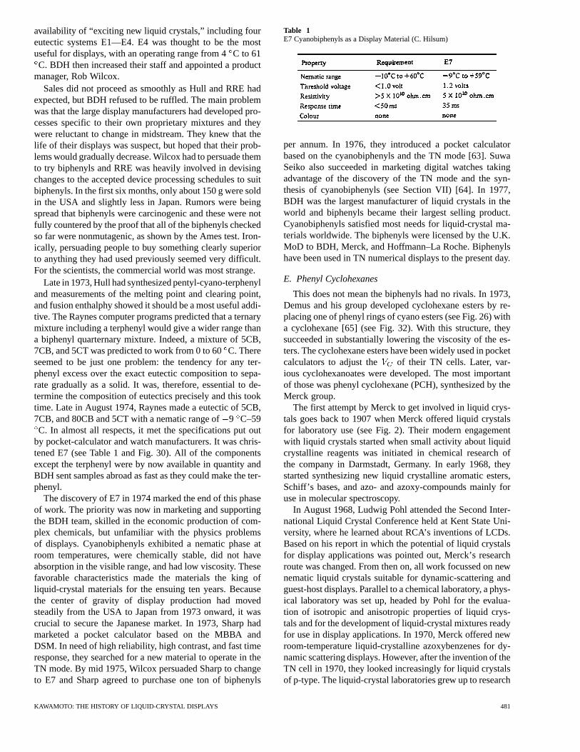
availability of “exciting new liquid crystals,” including foureutectic systems E1—E4. E4 was thought to be the mostuseful for displays, with an operating range from 4C to 61C. BDH then increased their staff and appointed a product
manager, Rob Wilcox.Sales did not proceed as smoothly as Hull and RRE had
expected, but BDH refused to be ruffled. The main problemwas that the large display manufacturers had developed pro-cesses specific to their own proprietary mixtures and theywere reluctant to change in midstream. They knew that thelife of their displays was suspect, but hoped that their prob-lems would gradually decrease. Wilcox had to persuade themto try biphenyls and RRE was heavily involved in devisingchanges to the accepted device processing schedules to suitbiphenyls. In the first six months, only about 150 g were soldin the USA and slightly less in Japan. Rumors were beingspread that biphenyls were carcinogenic and these were notfully countered by the proof that all of the biphenyls checkedso far were nonmutagenic, as shown by the Ames test. Iron-ically, persuading people to buy something clearly superiorto anything they had used previously seemed very difficult.For the scientists, the commercial world was most strange.
Late in 1973, Hull had synthesized pentyl-cyano-terphenyland measurements of the melting point and clearing point,and fusion enthalphy showed it should be a most useful addi-tive. The Raynes computer programs predicted that a ternarymixture including a terphenyl would give a wider range thana biphenyl quarternary mixture. Indeed, a mixture of 5CB,7CB, and 5CT was predicted to work from 0 to 60C. Thereseemed to be just one problem: the tendency for any ter-phenyl excess over the exact eutectic composition to sepa-rate gradually as a solid. It was, therefore, essential to de-termine the composition of eutectics precisely and this tooktime. Late in August 1974, Raynes made a eutectic of 5CB,7CB, and 80CB and 5CT with a nematic range of9 C–59C. In almost all respects, it met the specifications put out
by pocket-calculator and watch manufacturers. It was chris-tened E7 (see Table 1 and Fig. 30). All of the componentsexcept the terphenyl were by now available in quantity andBDH sent samples abroad as fast as they could make the ter-phenyl.
The discovery of E7 in 1974 marked the end of this phaseof work. The priority was now in marketing and supportingthe BDH team, skilled in the economic production of com-plex chemicals, but unfamiliar with the physics problemsof displays. Cyanobiphenyls exhibited a nematic phase atroom temperatures, were chemically stable, did not haveabsorption in the visible range, and had low viscosity. Thesefavorable characteristics made the materials the king ofliquid-crystal materials for the ensuing ten years. Becausethe center of gravity of display production had movedsteadily from the USA to Japan from 1973 onward, it wascrucial to secure the Japanese market. In 1973, Sharp hadmarketed a pocket calculator based on the MBBA andDSM. In need of high reliability, high contrast, and fast timeresponse, they searched for a new material to operate in theTN mode. By mid 1975, Wilcox persuaded Sharp to changeto E7 and Sharp agreed to purchase one ton of biphenyls
Table 1E7 Cyanobiphenyls as a Display Material (C. Hilsum)
per annum. In 1976, they introduced a pocket calculatorbased on the cyanobiphenyls and the TN mode [63]. SuwaSeiko also succeeded in marketing digital watches takingadvantage of the discovery of the TN mode and the syn-thesis of cyanobiphenyls (see Section VII) [64]. In 1977,BDH was the largest manufacturer of liquid crystals in theworld and biphenyls became their largest selling product.Cyanobiphenyls satisfied most needs for liquid-crystal ma-terials worldwide. The biphenyls were licensed by the U.K.MoD to BDH, Merck, and Hoffmann–La Roche. Biphenylshave been used in TN numerical displays to the present day.
E. Phenyl Cyclohexanes
This does not mean the biphenyls had no rivals. In 1973,Demus and his group developed cyclohexane esters by re-placing one of phenyl rings of cyano esters (see Fig. 26) witha cyclohexane [65] (see Fig. 32). With this structure, theysucceeded in substantially lowering the viscosity of the es-ters. The cyclohexane esters have been widely used in pocketcalculators to adjust the of their TN cells. Later, var-ious cyclohexanoates were developed. The most importantof those was phenyl cyclohexane (PCH), synthesized by theMerck group.
The first attempt by Merck to get involved in liquid crys-tals goes back to 1907 when Merck offered liquid crystalsfor laboratory use (see Fig. 2). Their modern engagementwith liquid crystals started when small activity about liquidcrystalline reagents was initiated in chemical research ofthe company in Darmstadt, Germany. In early 1968, theystarted synthesizing new liquid crystalline aromatic esters,Schiff’s bases, and azo- and azoxy-compounds mainly foruse in molecular spectroscopy.
In August 1968, Ludwig Pohl attended the Second Inter-national Liquid Crystal Conference held at Kent State Uni-versity, where he learned about RCA’s inventions of LCDs.Based on his report in which the potential of liquid crystalsfor display applications was pointed out, Merck’s researchroute was changed. From then on, all work focussed on newnematic liquid crystals suitable for dynamic-scattering andguest-host displays. Parallel to a chemical laboratory, a phys-ical laboratory was set up, headed by Pohl for the evalua-tion of isotropic and anisotropic properties of liquid crys-tals and for the development of liquid-crystal mixtures readyfor use in display applications. In 1970, Merck offered newroom-temperature liquid-crystalline azoxybenzenes for dy-namic scattering displays. However, after the invention of theTN cell in 1970, they looked increasingly for liquid crystalsof p-type. The liquid-crystal laboratories grew up to research
KAWAMOTO: THE HISTORY OF LIQUID-CRYSTAL DISPLAYS 481
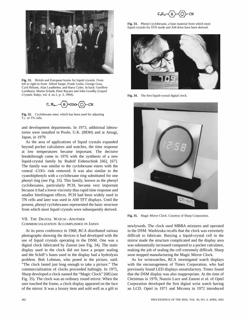
Fig. 31. British and European brains for liquid crystals. Fromleft to right in front: Alfred Saupe, Frank Leslie, George Gray,Cyril Hilsum, Alan Leadbetter, and Harry Coles. In back: GeoffreyLuchhurst, Martin Schadt, Peter Raynes and John Goodby (LiquidCrystals Today, vol. 4. no.1, p. 3, 1994).
Fig. 32. Cyclohexane ester, which has been used for adjustingV of TN cells.
and development departments. In 1973, additional labora-tories were installed in Poole, U.K. (BDH) and at Atsugi,Japan, in 1979.
As the area of applications of liquid crystals expandedbeyond pocket calculators and watches, the time responseat low temperatures became important. The decisivebreakthrough came in 1976 with the synthesis of a newliquid-crystal family by Rudolf Eidenschink [66], [67].The family was similar to the cyclohexane esters with thecentral -COO- rink removed. It was also similar to thecyanobiphenyls with a cyclohexane ring substituted for onephenyl ring (see Fig. 33). This family, known as the phenylcyclohexanes, particularly PCH, became very importantbecause it had a lower viscosity thus rapid time response andsmaller birefringent effects. PCH had been widely used inTN cells and later was used in AM TFT displays. Until thepresent, phenyl cyclohexanes represented the basic structurefrom which most liquid crystals were subsequently derived.
VII. T HE DIGITAL WATCH—ANOTHER
COMMERCIALIZATION ACCOMPLISHED INJAPAN
At its press conference in 1968, RCA distributed variousphotographs showing the devices it had developed with theuse of liquid crystals operating in the DSM. One was adigital clock fabricated by Zanoni (see Fig. 34). The staticdisplay used in the clock did not have a proper sealingand the Schiff’s bases used in the display had a hydrolysisproblem. Bob Lohman, who posed in the picture, said:“The clock lasted just long enough to take a picture.” Thecommercialization of clocks proceeded haltingly. In 1975,Sharp developed a clock named the “Magic Clock” [68] (seeFig. 35). The clock was an ordinary round mirror. When theuser touched the frame, a clock display appeared on the faceof the mirror. It was a luxury item and sold well as a gift to
Fig. 33. Phenyl cyclohexane, a base material from which mostliquid crystals for STN mode and AM drive have been derived.
Fig. 34. The first liquid-crystal digital clock.
Fig. 35. Magic Mirror Clock. Courtesy of Sharp Corporation.
newlyweds. The clock used MBBA mixtures and operatedin the DSM. Washizuka recalls that the clock was extremelydifficult to fabricate. Burying a liquid-crystal cell in themirror made the structure complicated and the display areawas substantially increased compared to a pocket calculator,making the job of sealing the cell extremely difficult. Sharpsoon stopped manufacturing the Magic Mirror Clock.
As for wristwatches, RCA investigated watch displayswith the encouragement of Timex Corporation, who hadpreviously found LED displays unsatisfactory. Timex foundthat the DSM display was also inappropriate. At the time ofChristmas in 1970, Nunzio Luce and Zanoniet al. of OptelCorporation developed the first digital wrist watch havingan LCD. Optel in 1971 and Micoma in 1972 introduced
482 PROCEEDINGS OF THE IEEE, VOL. 90, NO. 4, APRIL 2002
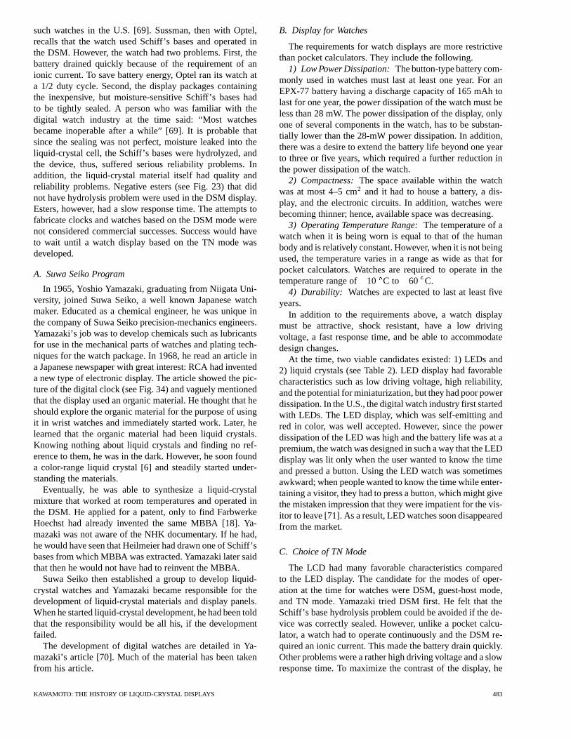
such watches in the U.S. [69]. Sussman, then with Optel,recalls that the watch used Schiff’s bases and operated inthe DSM. However, the watch had two problems. First, thebattery drained quickly because of the requirement of anionic current. To save battery energy, Optel ran its watch ata 1/2 duty cycle. Second, the display packages containingthe inexpensive, but moisture-sensitive Schiff’s bases hadto be tightly sealed. A person who was familiar with thedigital watch industry at the time said: “Most watchesbecame inoperable after a while” [69]. It is probable thatsince the sealing was not perfect, moisture leaked into theliquid-crystal cell, the Schiff’s bases were hydrolyzed, andthe device, thus, suffered serious reliability problems. Inaddition, the liquid-crystal material itself had quality andreliability problems. Negative esters (see Fig. 23) that didnot have hydrolysis problem were used in the DSM display.Esters, however, had a slow response time. The attempts tofabricate clocks and watches based on the DSM mode werenot considered commercial successes. Success would haveto wait until a watch display based on the TN mode wasdeveloped.
A. Suwa Seiko Program
In 1965, Yoshio Yamazaki, graduating from Niigata Uni-versity, joined Suwa Seiko, a well known Japanese watchmaker. Educated as a chemical engineer, he was unique inthe company of Suwa Seiko precision-mechanics engineers.Yamazaki’s job was to develop chemicals such as lubricantsfor use in the mechanical parts of watches and plating tech-niques for the watch package. In 1968, he read an article ina Japanese newspaper with great interest: RCA had inventeda new type of electronic display. The article showed the pic-ture of the digital clock (see Fig. 34) and vaguely mentionedthat the display used an organic material. He thought that heshould explore the organic material for the purpose of usingit in wrist watches and immediately started work. Later, helearned that the organic material had been liquid crystals.Knowing nothing about liquid crystals and finding no ref-erence to them, he was in the dark. However, he soon founda color-range liquid crystal [6] and steadily started under-standing the materials.
Eventually, he was able to synthesize a liquid-crystalmixture that worked at room temperatures and operated inthe DSM. He applied for a patent, only to find FarbwerkeHoechst had already invented the same MBBA [18]. Ya-mazaki was not aware of the NHK documentary. If he had,he would have seen that Heilmeier had drawn one of Schiff’sbases from which MBBA was extracted. Yamazaki later saidthat then he would not have had to reinvent the MBBA.
Suwa Seiko then established a group to develop liquid-crystal watches and Yamazaki became responsible for thedevelopment of liquid-crystal materials and display panels.When he started liquid-crystal development, he had been toldthat the responsibility would be all his, if the developmentfailed.
The development of digital watches are detailed in Ya-mazaki’s article [70]. Much of the material has been takenfrom his article.
B. Display for Watches
The requirements for watch displays are more restrictivethan pocket calculators. They include the following.
1) Low Power Dissipation:The button-type battery com-monly used in watches must last at least one year. For anEPX-77 battery having a discharge capacity of 165 mAh tolast for one year, the power dissipation of the watch must beless than 28 mW. The power dissipation of the display, onlyone of several components in the watch, has to be substan-tially lower than the 28-mW power dissipation. In addition,there was a desire to extend the battery life beyond one yearto three or five years, which required a further reduction inthe power dissipation of the watch.
2) Compactness:The space available within the watchwas at most 4–5 cmand it had to house a battery, a dis-play, and the electronic circuits. In addition, watches werebecoming thinner; hence, available space was decreasing.
3) Operating Temperature Range:The temperature of awatch when it is being worn is equal to that of the humanbody and is relatively constant. However, when it is not beingused, the temperature varies in a range as wide as that forpocket calculators. Watches are required to operate in thetemperature range of10 C to 60 C.
4) Durability: Watches are expected to last at least fiveyears.
In addition to the requirements above, a watch displaymust be attractive, shock resistant, have a low drivingvoltage, a fast response time, and be able to accommodatedesign changes.
At the time, two viable candidates existed: 1) LEDs and2) liquid crystals (see Table 2). LED display had favorablecharacteristics such as low driving voltage, high reliability,and the potential for miniaturization, but they had poor powerdissipation. In the U.S., the digital watch industry first startedwith LEDs. The LED display, which was self-emitting andred in color, was well accepted. However, since the powerdissipation of the LED was high and the battery life was at apremium, the watch was designed in such a way that the LEDdisplay was lit only when the user wanted to know the timeand pressed a button. Using the LED watch was sometimesawkward; when people wanted to know the time while enter-taining a visitor, they had to press a button, which might givethe mistaken impression that they were impatient for the vis-itor to leave [71]. As a result, LED watches soon disappearedfrom the market.
C. Choice of TN Mode
The LCD had many favorable characteristics comparedto the LED display. The candidate for the modes of oper-ation at the time for watches were DSM, guest-host mode,and TN mode. Yamazaki tried DSM first. He felt that theSchiff’s base hydrolysis problem could be avoided if the de-vice was correctly sealed. However, unlike a pocket calcu-lator, a watch had to operate continuously and the DSM re-quired an ionic current. This made the battery drain quickly.Other problems were a rather high driving voltage and a slowresponse time. To maximize the contrast of the display, he
KAWAMOTO: THE HISTORY OF LIQUID-CRYSTAL DISPLAYS 483
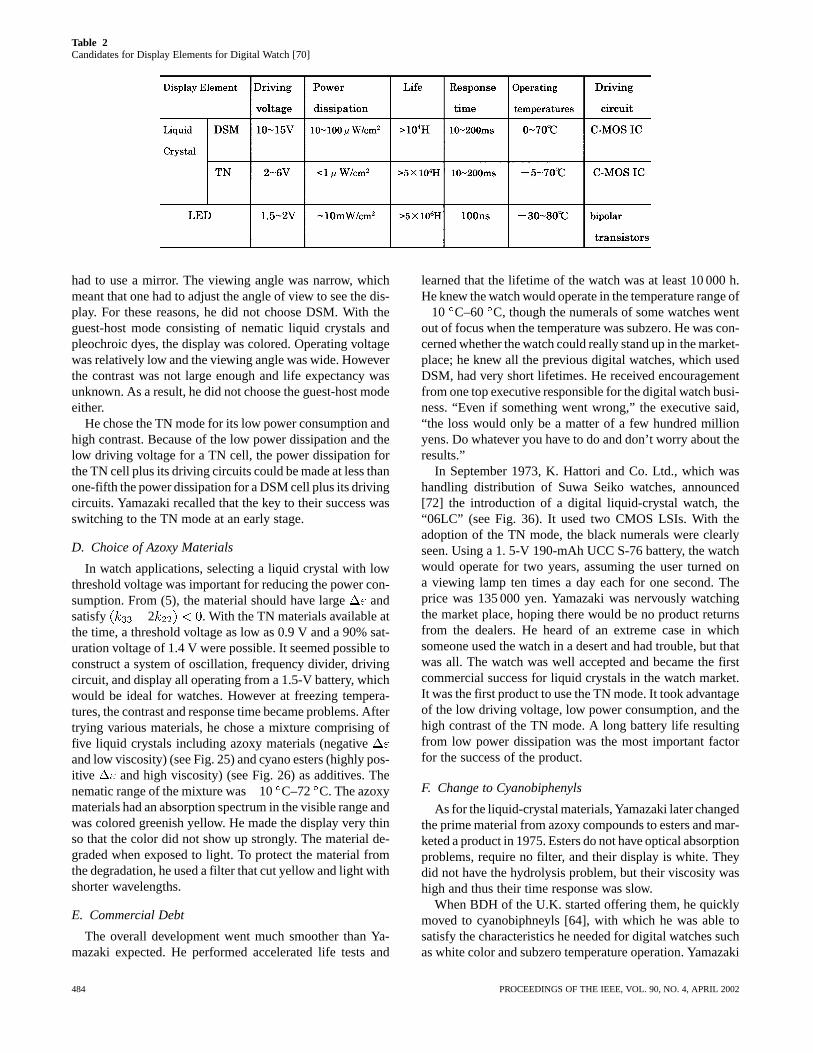
Table 2Candidates for Display Elements for Digital Watch [70]
had to use a mirror. The viewing angle was narrow, whichmeant that one had to adjust the angle of view to see the dis-play. For these reasons, he did not choose DSM. With theguest-host mode consisting of nematic liquid crystals andpleochroic dyes, the display was colored. Operating voltagewas relatively low and the viewing angle was wide. Howeverthe contrast was not large enough and life expectancy wasunknown. As a result, he did not choose the guest-host modeeither.
He chose the TN mode for its low power consumption andhigh contrast. Because of the low power dissipation and thelow driving voltage for a TN cell, the power dissipation forthe TN cell plus its driving circuits could be made at less thanone-fifth the power dissipation for a DSM cell plus its drivingcircuits. Yamazaki recalled that the key to their success wasswitching to the TN mode at an early stage.
D. Choice of Azoxy Materials
In watch applications, selecting a liquid crystal with lowthreshold voltage was important for reducing the power con-sumption. From (5), the material should have largeandsatisfy 2 . With the TN materials available atthe time, a threshold voltage as low as 0.9 V and a 90% sat-uration voltage of 1.4 V were possible. It seemed possible toconstruct a system of oscillation, frequency divider, drivingcircuit, and display all operating from a 1.5-V battery, whichwould be ideal for watches. However at freezing tempera-tures, the contrast and response time became problems. Aftertrying various materials, he chose a mixture comprising offive liquid crystals including azoxy materials (negativeand low viscosity) (see Fig. 25) and cyano esters (highly pos-itive and high viscosity) (see Fig. 26) as additives. Thenematic range of the mixture was10 C–72 C. The azoxymaterials had an absorption spectrum in the visible range andwas colored greenish yellow. He made the display very thinso that the color did not show up strongly. The material de-graded when exposed to light. To protect the material fromthe degradation, he used a filter that cut yellow and light withshorter wavelengths.
E. Commercial Debt
The overall development went much smoother than Ya-mazaki expected. He performed accelerated life tests and
learned that the lifetime of the watch was at least 10 000 h.He knew the watch would operate in the temperature range of
10 C–60 C, though the numerals of some watches wentout of focus when the temperature was subzero. He was con-cerned whether the watch could really stand up in the market-place; he knew all the previous digital watches, which usedDSM, had very short lifetimes. He received encouragementfrom one top executive responsible for the digital watch busi-ness. “Even if something went wrong,” the executive said,“the loss would only be a matter of a few hundred millionyens. Do whatever you have to do and don’t worry about theresults.”
In September 1973, K. Hattori and Co. Ltd., which washandling distribution of Suwa Seiko watches, announced[72] the introduction of a digital liquid-crystal watch, the“06LC” (see Fig. 36). It used two CMOS LSIs. With theadoption of the TN mode, the black numerals were clearlyseen. Using a 1. 5-V 190-mAh UCC S-76 battery, the watchwould operate for two years, assuming the user turned ona viewing lamp ten times a day each for one second. Theprice was 135 000 yen. Yamazaki was nervously watchingthe market place, hoping there would be no product returnsfrom the dealers. He heard of an extreme case in whichsomeone used the watch in a desert and had trouble, but thatwas all. The watch was well accepted and became the firstcommercial success for liquid crystals in the watch market.It was the first product to use the TN mode. It took advantageof the low driving voltage, low power consumption, and thehigh contrast of the TN mode. A long battery life resultingfrom low power dissipation was the most important factorfor the success of the product.
F. Change to Cyanobiphenyls
As for the liquid-crystal materials, Yamazaki later changedthe prime material from azoxy compounds to esters and mar-keted a product in 1975. Esters do not have optical absorptionproblems, require no filter, and their display is white. Theydid not have the hydrolysis problem, but their viscosity washigh and thus their time response was slow.
When BDH of the U.K. started offering them, he quicklymoved to cyanobiphneyls [64], with which he was able tosatisfy the characteristics he needed for digital watches suchas white color and subzero temperature operation. Yamazaki
484 PROCEEDINGS OF THE IEEE, VOL. 90, NO. 4, APRIL 2002
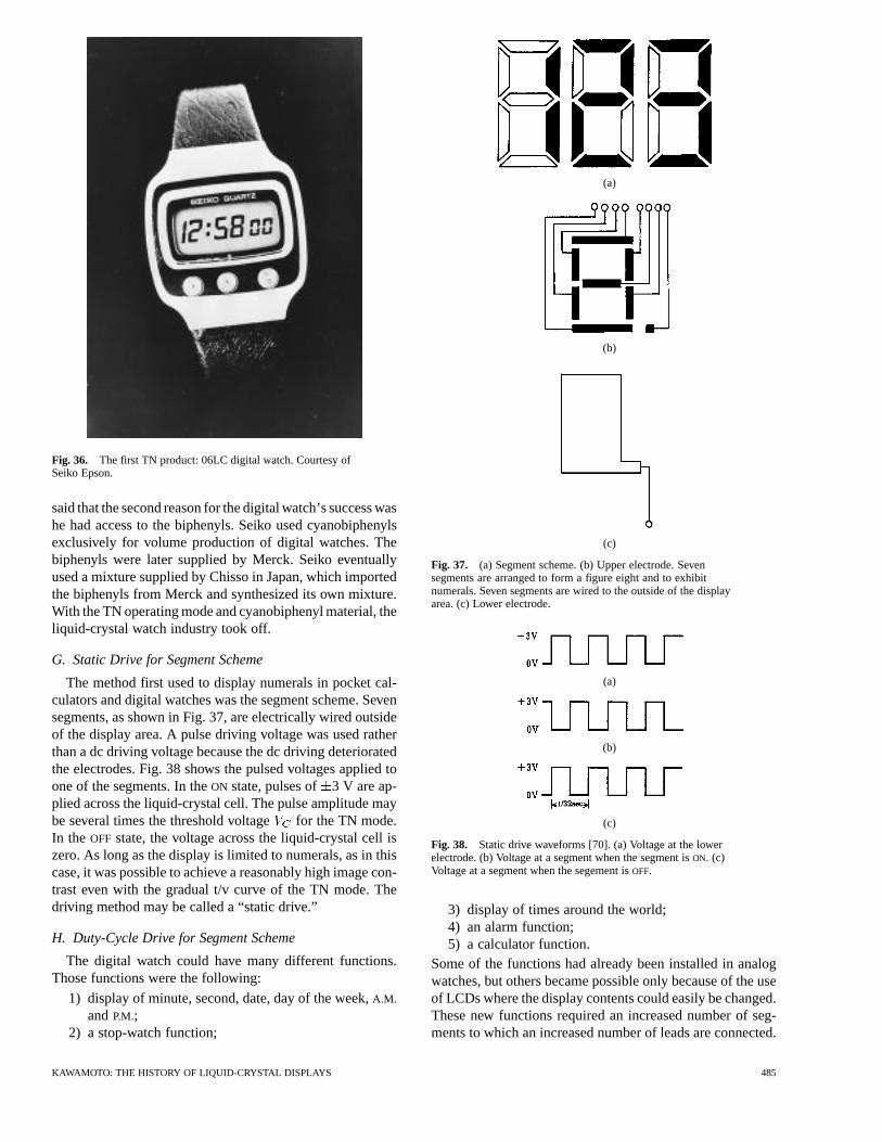
Fig. 36. The first TN product: 06LC digital watch. Courtesy ofSeiko Epson.
said that the second reason for the digital watch’s success washe had access to the biphenyls. Seiko used cyanobiphenylsexclusively for volume production of digital watches. Thebiphenyls were later supplied by Merck. Seiko eventuallyused a mixture supplied by Chisso in Japan, which importedthe biphenyls from Merck and synthesized its own mixture.With the TN operating mode and cyanobiphenyl material, theliquid-crystal watch industry took off.
G. Static Drive for Segment Scheme
The method first used to display numerals in pocket cal-culators and digital watches was the segment scheme. Sevensegments, as shown in Fig. 37, are electrically wired outsideof the display area. A pulse driving voltage was used ratherthan a dc driving voltage because the dc driving deterioratedthe electrodes. Fig. 38 shows the pulsed voltages applied toone of the segments. In theON state, pulses of 3 V are ap-plied across the liquid-crystal cell. The pulse amplitude maybe several times the threshold voltage for the TN mode.In the OFF state, the voltage across the liquid-crystal cell iszero. As long as the display is limited to numerals, as in thiscase, it was possible to achieve a reasonably high image con-trast even with the gradual t/v curve of the TN mode. Thedriving method may be called a “static drive.”
H. Duty-Cycle Drive for Segment Scheme
The digital watch could have many different functions.Those functions were the following:
1) display of minute, second, date, day of the week,A.M.
andP.M.;2) a stop-watch function;
(a)
(b)
(c)
Fig. 37. (a) Segment scheme. (b) Upper electrode. Sevensegments are arranged to form a figure eight and to exhibitnumerals. Seven segments are wired to the outside of the displayarea. (c) Lower electrode.
(a)
(b)
(c)
Fig. 38. Static drive waveforms [70]. (a) Voltage at the lowerelectrode. (b) Voltage at a segment when the segment isON. (c)Voltage at a segment when the segement isOFF.
3) display of times around the world;4) an alarm function;5) a calculator function.
Some of the functions had already been installed in analogwatches, but others became possible only because of the useof LCDs where the display contents could easily be changed.These new functions required an increased number of seg-ments to which an increased number of leads are connected.
KAWAMOTO: THE HISTORY OF LIQUID-CRYSTAL DISPLAYS 485
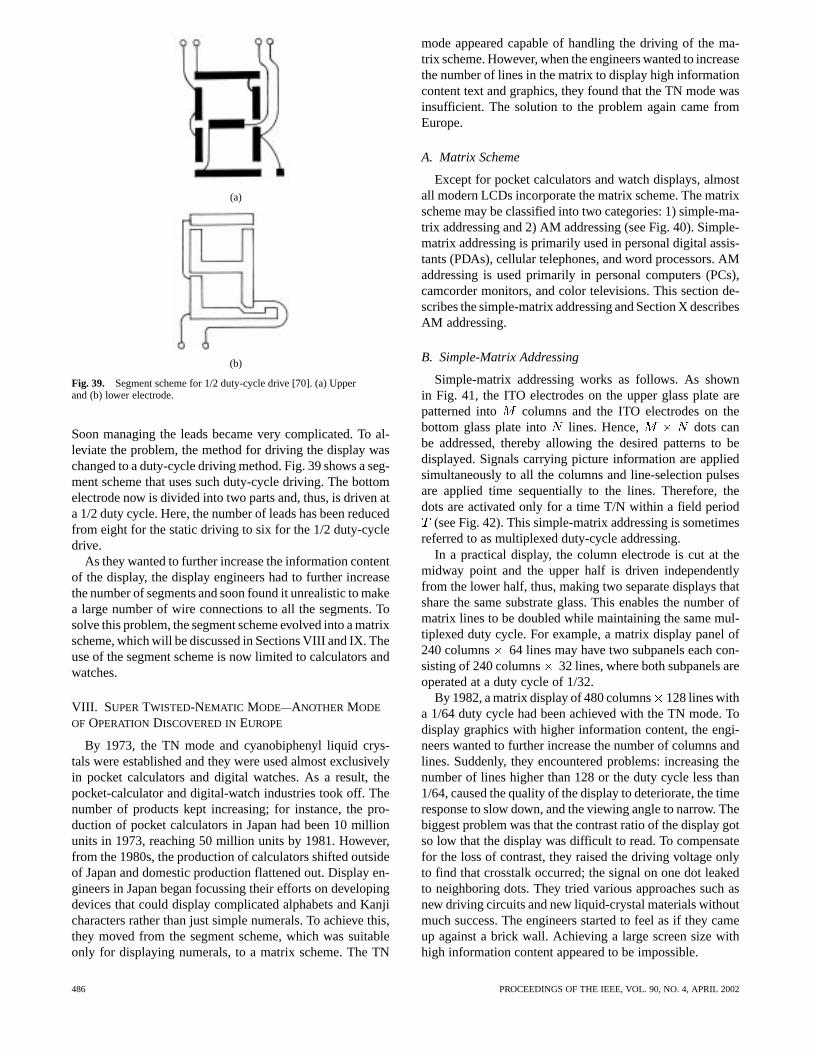
(a)
(b)
Fig. 39. Segment scheme for 1/2 duty-cycle drive [70]. (a) Upperand (b) lower electrode.
Soon managing the leads became very complicated. To al-leviate the problem, the method for driving the display waschanged to a duty-cycle driving method. Fig. 39 shows a seg-ment scheme that uses such duty-cycle driving. The bottomelectrode now is divided into two parts and, thus, is driven ata 1/2 duty cycle. Here, the number of leads has been reducedfrom eight for the static driving to six for the 1/2 duty-cycledrive.
As they wanted to further increase the information contentof the display, the display engineers had to further increasethe number of segments and soon found it unrealistic to makea large number of wire connections to all the segments. Tosolve this problem, the segment scheme evolved into a matrixscheme, which will be discussed in Sections VIII and IX. Theuse of the segment scheme is now limited to calculators andwatches.
VIII. SUPERTWISTED-NEMATIC MODE—ANOTHER MODE
OF OPERATION DISCOVERED INEUROPE
By 1973, the TN mode and cyanobiphenyl liquid crys-tals were established and they were used almost exclusivelyin pocket calculators and digital watches. As a result, thepocket-calculator and digital-watch industries took off. Thenumber of products kept increasing; for instance, the pro-duction of pocket calculators in Japan had been 10 millionunits in 1973, reaching 50 million units by 1981. However,from the 1980s, the production of calculators shifted outsideof Japan and domestic production flattened out. Display en-gineers in Japan began focussing their efforts on developingdevices that could display complicated alphabets and Kanjicharacters rather than just simple numerals. To achieve this,they moved from the segment scheme, which was suitableonly for displaying numerals, to a matrix scheme. The TN
mode appeared capable of handling the driving of the ma-trix scheme. However, when the engineers wanted to increasethe number of lines in the matrix to display high informationcontent text and graphics, they found that the TN mode wasinsufficient. The solution to the problem again came fromEurope.
A. Matrix Scheme
Except for pocket calculators and watch displays, almostall modern LCDs incorporate the matrix scheme. The matrixscheme may be classified into two categories: 1) simple-ma-trix addressing and 2) AM addressing (see Fig. 40). Simple-matrix addressing is primarily used in personal digital assis-tants (PDAs), cellular telephones, and word processors. AMaddressing is used primarily in personal computers (PCs),camcorder monitors, and color televisions. This section de-scribes the simple-matrix addressing and Section X describesAM addressing.
B. Simple-Matrix Addressing
Simple-matrix addressing works as follows. As shownin Fig. 41, the ITO electrodes on the upper glass plate arepatterned into columns and the ITO electrodes on thebottom glass plate into lines. Hence, dots canbe addressed, thereby allowing the desired patterns to bedisplayed. Signals carrying picture information are appliedsimultaneously to all the columns and line-selection pulsesare applied time sequentially to the lines. Therefore, thedots are activated only for a time T/N within a field period
(see Fig. 42). This simple-matrix addressing is sometimesreferred to as multiplexed duty-cycle addressing.
In a practical display, the column electrode is cut at themidway point and the upper half is driven independentlyfrom the lower half, thus, making two separate displays thatshare the same substrate glass. This enables the number ofmatrix lines to be doubled while maintaining the same mul-tiplexed duty cycle. For example, a matrix display panel of240 columns 64 lines may have two subpanels each con-sisting of 240 columns 32 lines, where both subpanels areoperated at a duty cycle of 1/32.
By 1982, a matrix display of 480 columns128 lines witha 1/64 duty cycle had been achieved with the TN mode. Todisplay graphics with higher information content, the engi-neers wanted to further increase the number of columns andlines. Suddenly, they encountered problems: increasing thenumber of lines higher than 128 or the duty cycle less than1/64, caused the quality of the display to deteriorate, the timeresponse to slow down, and the viewing angle to narrow. Thebiggest problem was that the contrast ratio of the display gotso low that the display was difficult to read. To compensatefor the loss of contrast, they raised the driving voltage onlyto find that crosstalk occurred; the signal on one dot leakedto neighboring dots. They tried various approaches such asnew driving circuits and new liquid-crystal materials withoutmuch success. The engineers started to feel as if they cameup against a brick wall. Achieving a large screen size withhigh information content appeared to be impossible.
486 PROCEEDINGS OF THE IEEE, VOL. 90, NO. 4, APRIL 2002
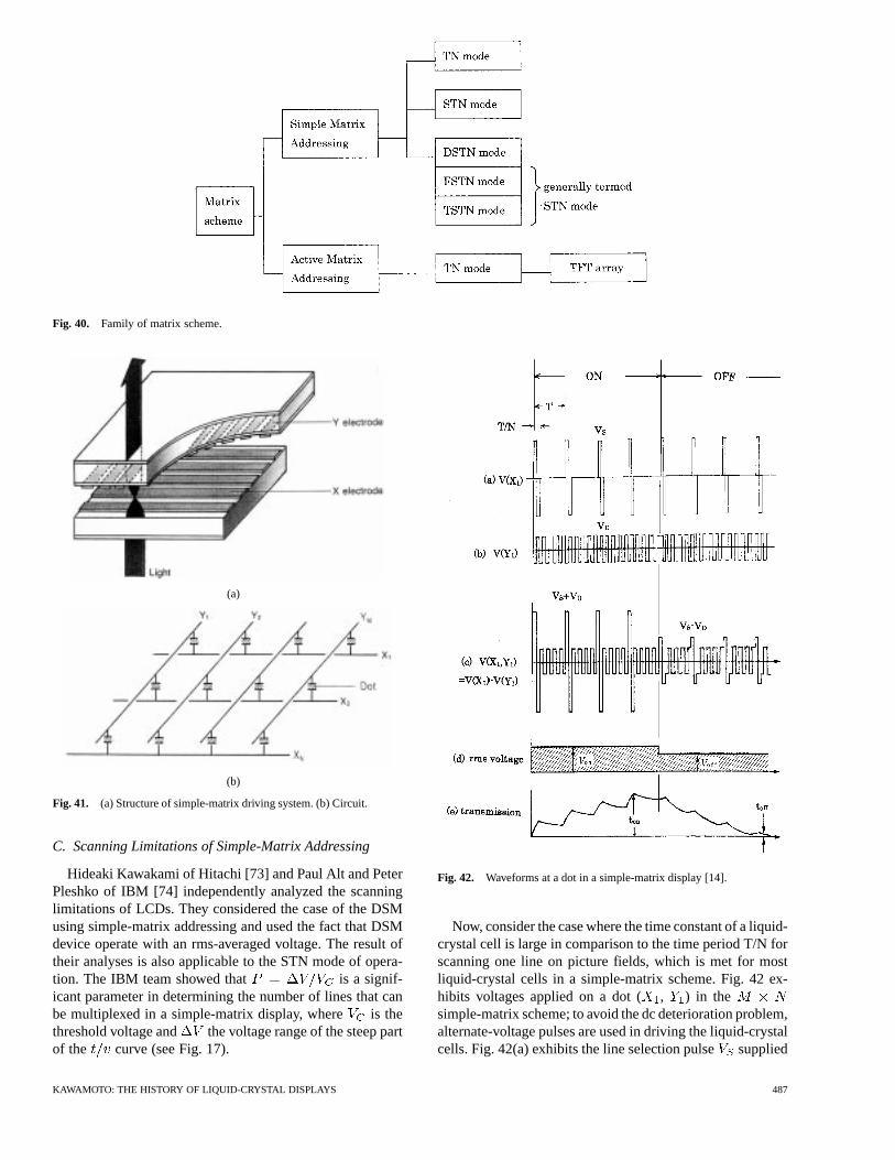
Fig. 40. Family of matrix scheme.
(a)
(b)
Fig. 41. (a) Structure of simple-matrix driving system. (b) Circuit.
C. Scanning Limitations of Simple-Matrix Addressing
Hideaki Kawakami of Hitachi [73] and Paul Alt and PeterPleshko of IBM [74] independently analyzed the scanninglimitations of LCDs. They considered the case of the DSMusing simple-matrix addressing and used the fact that DSMdevice operate with an rms-averaged voltage. The result oftheir analyses is also applicable to the STN mode of opera-tion. The IBM team showed that is a signif-icant parameter in determining the number of lines that canbe multiplexed in a simple-matrix display, where is thethreshold voltage and the voltage range of the steep partof the curve (see Fig. 17).
Fig. 42. Waveforms at a dot in a simple-matrix display [14].
Now, consider the case where the time constant of a liquid-crystal cell is large in comparison to the time period T/N forscanning one line on picture fields, which is met for mostliquid-crystal cells in a simple-matrix scheme. Fig. 42 ex-hibits voltages applied on a dot ( , ) in thesimple-matrix scheme; to avoid the dc deterioration problem,alternate-voltage pulses are used in driving the liquid-crystalcells. Fig. 42(a) exhibits the line selection pulsesupplied
KAWAMOTO: THE HISTORY OF LIQUID-CRYSTAL DISPLAYS 487
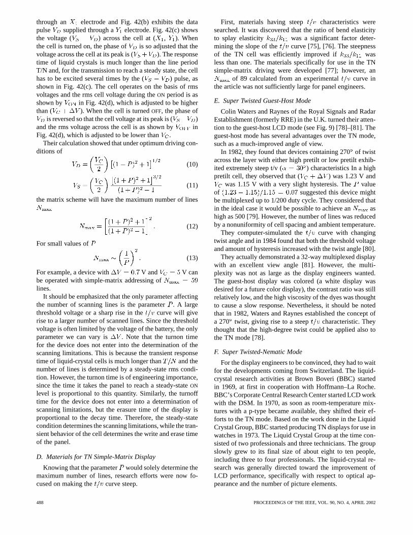
through an electrode and Fig. 42(b) exhibits the datapulse supplied through a electrode. Fig. 42(c) showsthe voltage ( ) across the cell at ( , ). Whenthe cell is turned on, the phase of is so adjusted that thevoltage across the cell at its peak is ( ). The responsetime of liquid crystals is much longer than the line periodT/N and, for the transmission to reach a steady state, the cellhas to be excited several times by the ( ) pulse, asshown in Fig. 42(c). The cell operates on the basis of rmsvoltages and the rms cell voltage during theON period is asshown by in Fig. 42(d), which is adjusted to be higherthan ( ). When the cell is turnedOFF, the phase of
is reversed so that the cell voltage at its peak is ( )and the rms voltage across the cell is as shown by inFig. 42(d), which is adjusted to be lower than.
Their calculation showed that under optimum driving con-ditions of
(10)
(11)
the matrix scheme will have the maximum number of lines
(12)
For small values of
(13)
For example, a device with V and V canbe operated with simple-matrix addressing oflines.
It should be emphasized that the only parameter affectingthe number of scanning lines is the parameter. A largethreshold voltage or a sharp rise in the curve will giverise to a larger number of scanned lines. Since the thresholdvoltage is often limited by the voltage of the battery, the onlyparameter we can vary is . Note that the turnon timefor the device does not enter into the determination of thescanning limitations. This is because the transient responsetime of liquid-crystal cells is much longer than and thenumber of lines is determined by a steady-state rms condi-tion. However, the turnon time is of engineering importance,since the time it takes the panel to reach a steady-stateON
level is proportional to this quantity. Similarly, the turnofftime for the device does not enter into a determination ofscanning limitations, but the erasure time of the display isproportional to the decay time. Therefore, the steady-statecondition determines the scanning limitations, while the tran-sient behavior of the cell determines the write and erase timeof the panel.
D. Materials for TN Simple-Matrix Display
Knowing that the parameter would solely determine themaximum number of lines, research efforts were now fo-cused on making the curve steep.
First, materials having steep characteristics weresearched. It was discovered that the ratio of bend elasticityto splay elasticity was a significant factor deter-mining the slope of the curve [75], [76]. The steepnessof the TN cell was efficiently improved if wasless than one. The materials specifically for use in the TNsimple-matrix driving were developed [77]; however, an
of 89 calculated from an experimental curve inthe article was not sufficiently large for panel engineers.
E. Super Twisted Guest-Host Mode
Colin Waters and Raynes of the Royal Signals and RadarEstablishment (formerly RRE) in the U.K. turned their atten-tion to the guest-host LCD mode (see Fig. 9) [78]–[81]. Theguest-host mode has several advantages over the TN mode,such as a much-improved angle of view.
In 1982, they found that devices containing 270of twistacross the layer with either high pretilt or low pretilt exhib-ited extremely steep t/v ( ) characteristics In a highpretilt cell, they observed that ( ) was 1.23 V and
was 1.15 V with a very slight hysteresis. Thevalueof suggested this device mightbe multiplexed up to 1/200 duty cycle. They considered thatin the ideal case it would be possible to achieve an ashigh as 500 [79]. However, the number of lines was reducedby a nonuniformity of cell spacing and ambient temperature.
They computer-simulated the curve with changingtwist angle and in 1984 found that both the threshold voltageand amount of hysteresis increased with the twist angle [80].
They actually demonstrated a 32-way multiplexed displaywith an excellent view angle [81]. However, the multi-plexity was not as large as the display engineers wanted.The guest-host display was colored (a white display wasdesired for a future color display), the contrast ratio was stillrelatively low, and the high viscosity of the dyes was thoughtto cause a slow response. Nevertheless, it should be notedthat in 1982, Waters and Raynes established the concept ofa 270 twist, giving rise to a steep characteristic. Theythought that the high-degree twist could be applied also tothe TN mode [78].
F. Super Twisted-Nematic Mode
For the display engineers to be convinced, they had to waitfor the developments coming from Switzerland. The liquid-crystal research activities at Brown Boveri (BBC) startedin 1969, at first in cooperation with Hoffmann–La Roche.BBC’s Corporate Central Research Center started LCD workwith the DSM. In 1970, as soon as room-temperature mix-tures with a p-type became available, they shifted their ef-forts to the TN mode. Based on the work done in the LiquidCrystal Group, BBC started producing TN displays for use inwatches in 1973. The Liquid Crystal Group at the time con-sisted of two professionals and three technicians. The groupslowly grew to its final size of about eight to ten people,including three to four professionals. The liquid-crystal re-search was generally directed toward the improvement ofLCD performance, specifically with respect to optical ap-pearance and the number of picture elements.
488 PROCEEDINGS OF THE IEEE, VOL. 90, NO. 4, APRIL 2002
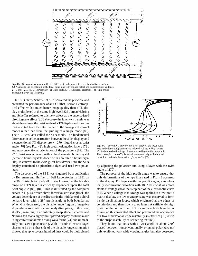
Fig. 43. Schematic view of a reflective STN matrix display with a left-handed twist angle of270 showing the orientation of the local optic axis with applied select and nonselect rms voltagesV andV [83]. (1) Polarizer. (2) Glass plate. (3) Transparent electrode. (4) High-pretiltorientation layer. (5) Reflector.
In 1983, Terry Schefferet al.discovered the principle andpresented the performance of an LCD that used an electroop-tical effect with a much better image quality than a TN dis-play multiplexed at the same high level [82]. Jürgen Nehringand Scheffer referred to this new effect as the supertwistedbirefringence effect (SBE) because the layer twist angle wasabout three times the twist angle of a TN display and the con-trast resulted from the interference of the two optical normalmodes rather than from the guiding of a single mode [83].The SBE was later called the STN mode. The fundamentaldifference in cell construction between the STN display anda conventional TN display are 270 liquid-crystal twistangle [78] (see Fig. 43), high pretilt orientation layers [78],and nonconventional orientation of the polarizers [82]. The270 twist was achieved with a chiral nematic liquid crystal(nematic liquid crystals doped with cholesteric liquid crys-tals). In contrast to the 270guest-host device [78], the STNdisplay contained no pleochroic dyes and used two polar-izers.
The discovery of the SBE was triggered by a publicationby Berreman and Heffner of Bell Laboratories in 1981 onthe 360 bistable twisted cell. It was known that the bistablerange of a TN layer is critically dependent upon the totaltwist angle [80], [84]. This is illustrated by the computercurves in Fig. 44, which show, for various twist angles, thevoltage dependence of the director in the midplane of a chiralnematic layer with a 28pretilt angle at both boundaries.When is decreased, the bistable range (region of negativeslope) decreases until it completely disappears, in this case,at 245 , resulting in an infinitely steep slope. Scheffer andNehring felt that a highly multiplexed display could be madeusing conventional rms driving waveforms [74] and immedi-ately built a two-pixel test rig. WithON andOFFrms voltageschosen to lie on either side of the bistable range, simulationshowed that up to several hundred lines could be multiplexed
Fig. 44. Theoretical curve of the twist angle of the local opticaxis in the layer midplane versus reduced voltageV=V , whereV is the threshold voltage of a nontwisted layer with zero pretilt.Thickness/pitch ratiod=p is varied simultaneously with the totaltwist� to maintain the relationd=p = �=2� [83].
by adjusting the polarizer and using a layer with the twistangle of 270.
The purpose of the high pretilt angle was to ensure thatonly deformations of the type illustrated in Fig. 43 occurredin the display. For layers with low pretilt angles, a topolog-ically inequivalent distortion with 180less twist was morestable at voltages near the steep part of the electrooptic curve[85]. When a voltage in this range was applied to a low-pretiltmatrix display, the lower energy state was observed to forminside disclination loops, which originated at the edges ofcertain dots and then slowly grew larger. A sufficiently highpretilt angle on the order of 5or more at both boundariesprevented this unwanted effect and prevented the occurrenceof a two-dimensional stripe instability. (Reference [79] refersto the stripe instability as scattering texture.)
They found that cells with a twist angle of about 270placed between nonconventionally oriented polarizers notonly exhibited very wide viewing angles but also possessed
KAWAMOTO: THE HISTORY OF LIQUID-CRYSTAL DISPLAYS 489
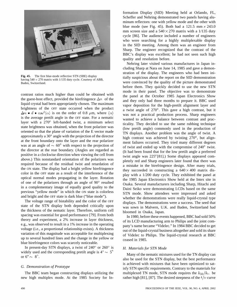
Fig. 45. The first blue-mode reflective STN (SBE) displayhaving 540� 270 matrix with 1/135 duty cycle. Courtesy of ABB,Baden, Switzerland.
contrast ratios much higher than could be obtained withthe guest-host effect, provided the birefringence of theliquid crystal had been appropriately chosen. The maximumbrightness of theOFF state occurred when the product
is on the order of 0.8 m, whereis the average pretilt angle in theOFF state. For a nematiclayer with a 270 left-handed twist, a minimum selectstate brightness was obtained, when the front polarizer wasoriented so that the plane of variation of the E vector madeapproximately a 30angle with the projection of the directorat the front boundary onto the layer and the rear polarizerwas at an angle of 60 with respect to the projection ofthe director at the rear boundary. (Angles are regarded aspositive in a clockwise direction when viewing the cell fromabove.) This nonstandard orientation of the polarizers wasrequired because of the residual twist and retardation ofthe ON state. The display had a bright yellow birefringencecolor in theOFF state as a result of the interference of theoptical normal modes propagating in the layer. Rotationof one of the polarizers through an angle of 90resultedin a complementary image of equally good quality to theprevious “yellow mode” in which theON state is colorlessand bright and theOFFstate is dark blue (“blue mode”).
The voltage range of bistability and the color of theOFF
state of the STN display both depended critically uponthe thickness of the nematic layer. Therefore, uniform cellspacing was essential for good performance [79]. From boththeory and experiment, a 2% increase in layer thickness,e.g., was observed to result in a 1% increase in the operatingvoltage (i.e., a proportional relationship exists). A thicknessvariation of this magnitude was acceptable for multiplexingup to several hundred lines and the change in the yellow orblue birefringence colors was scarcely noticeable.
In present-day STN displays, a twist of 240or 260 iswidely used and the corresponding pretilt angle is 45or 6 8 .
G. Demonstration of Prototype
The BBC team began constructing displays utilizing thenew high multiplex mode. At the 1985 Society for In-
formation Display (SID) Meeting held at Orlando, FL,Scheffer and Nehring demonstrated two panels having alu-minum reflectors: one with yellow mode and the other withblue mode (see Fig. 45). Both had a 121.5 mm243.0mm screen size and a 540270 matrix with a 1/135 dutycycle [86]. The audience included a number of engineerswho were searching for a highly multiplexable displayin the SID meeting. Among them was an engineer fromSharp. The engineer recognized that the contrast of theBBC’s display was excellent; he had not seen such highquality and resolution before.
Nehring later visited various manufactures in Japan in-cluding Sharp at Nara on June 14, 1985 and gave a demon-stration of the display. The engineers who had been ini-tially suspicious about the report on the SID demonstrationwere convinced by the quality of the picture demonstratedbefore them. They quickly decided to use the new STNmode in their panel. The objective was to demonstratethe panel at the October 1985 Japan Electronics Showand they only had three months to prepare it. BBC usedvapor deposition for the high-pretilt alignment layer anda twist angle of 270. This gave a high contrast, but itwas not a practical production process. Sharp engineerswanted to achieve a balance between contrast and prac-ticality. They decided to use the same rubbing technique(low pretilt angle) commonly used in the production ofTN displays. Another problem was the angle of twist. Ahigh contrast was achieved by twisting 270, but align-ment failures occurred. They tried many different degreesof twist and ended up with the compromise of 240twist.(It had been found that for the low pretilt angle a preferredtwist angle was 225[81].) Some displays appeared com-pletely red and Sharp engineers later found that there wasa mistake in the birefringence design. After many trials,they succeeded in constructing a 640400 matrix dis-play with a 1/200 duty cycle. They exhibited the panel atthe 1985 Japan Electronics Show held at the Intex site inOsaka. Several manufacturers including Sharp, Hitachi andDaini Seiko were demonstrating LCDs based on the sameSTN mode. Show attendees were impressed and askedwhether the demonstrations were really liquid-crystal typedisplays. The demonstrations were a success. The seed thatwas sown in Malvern, U.K. and Baden, Switzerland hadbloomed in Osaka, Japan.
In 1980, before these events happened, BBC had sold 50%of its LCD manufacturing arm to Philips and the joint com-pany’s name became “Videlec.” In 1984 BBC decided to getout of the liquid-crystal business altogether and sold its shareof Videlec to Philips. The liquid-crystal research at BBCceased in 1985.
H. Materials for STN Mode
Many of the nematic mixtures used for the TN display canalso be used for the STN display, but the best performanceis achieved with mixtures that have been optimized to sat-isfy STN specific requirements. Contrary to the materials formultiplexed TN mode, STN mode requires the berather high [81], [87]. The desired steepness of thecurve
490 PROCEEDINGS OF THE IEEE, VOL. 90, NO. 4, APRIL 2002
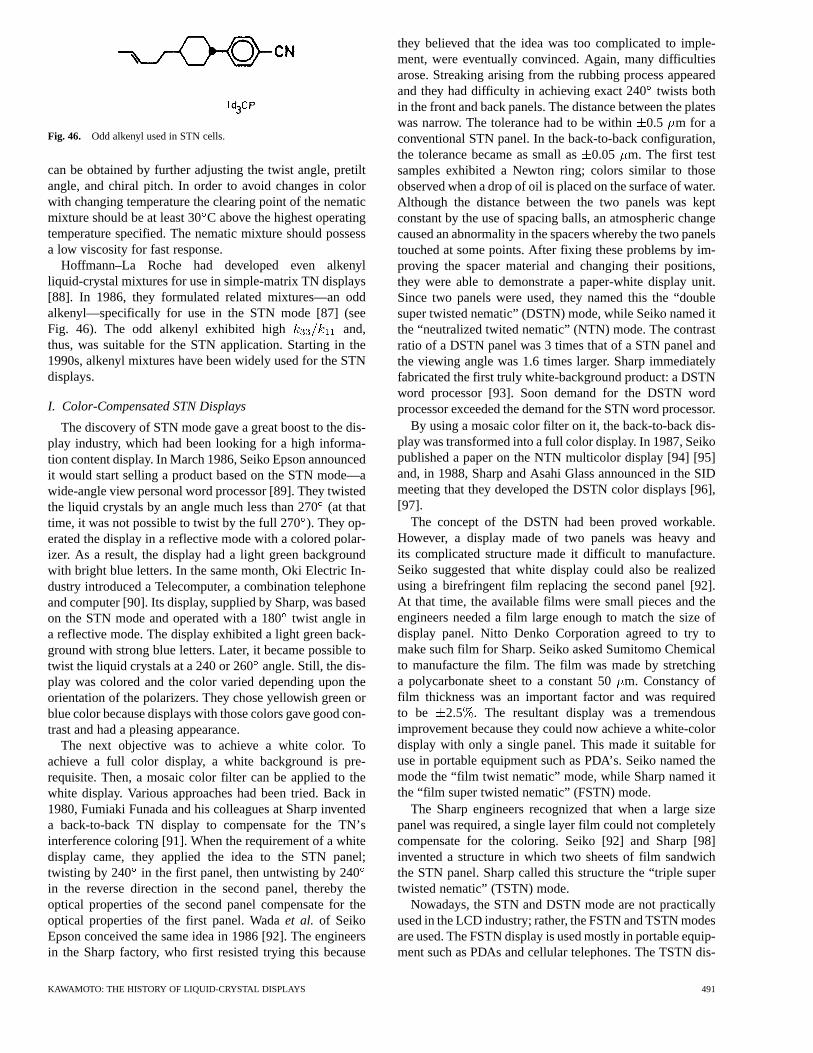
Fig. 46. Odd alkenyl used in STN cells.
can be obtained by further adjusting the twist angle, pretiltangle, and chiral pitch. In order to avoid changes in colorwith changing temperature the clearing point of the nematicmixture should be at least 30C above the highest operatingtemperature specified. The nematic mixture should possessa low viscosity for fast response.
Hoffmann–La Roche had developed even alkenylliquid-crystal mixtures for use in simple-matrix TN displays[88]. In 1986, they formulated related mixtures—an oddalkenyl—specifically for use in the STN mode [87] (seeFig. 46). The odd alkenyl exhibited high and,thus, was suitable for the STN application. Starting in the1990s, alkenyl mixtures have been widely used for the STNdisplays.
I. Color-Compensated STN Displays
The discovery of STN mode gave a great boost to the dis-play industry, which had been looking for a high informa-tion content display. In March 1986, Seiko Epson announcedit would start selling a product based on the STN mode—awide-angle view personal word processor [89]. They twistedthe liquid crystals by an angle much less than 270(at thattime, it was not possible to twist by the full 270). They op-erated the display in a reflective mode with a colored polar-izer. As a result, the display had a light green backgroundwith bright blue letters. In the same month, Oki Electric In-dustry introduced a Telecomputer, a combination telephoneand computer [90]. Its display, supplied by Sharp, was basedon the STN mode and operated with a 180twist angle ina reflective mode. The display exhibited a light green back-ground with strong blue letters. Later, it became possible totwist the liquid crystals at a 240 or 260angle. Still, the dis-play was colored and the color varied depending upon theorientation of the polarizers. They chose yellowish green orblue color because displays with those colors gave good con-trast and had a pleasing appearance.
The next objective was to achieve a white color. Toachieve a full color display, a white background is pre-requisite. Then, a mosaic color filter can be applied to thewhite display. Various approaches had been tried. Back in1980, Fumiaki Funada and his colleagues at Sharp inventeda back-to-back TN display to compensate for the TN’sinterference coloring [91]. When the requirement of a whitedisplay came, they applied the idea to the STN panel;twisting by 240 in the first panel, then untwisting by 240in the reverse direction in the second panel, thereby theoptical properties of the second panel compensate for theoptical properties of the first panel. Wadaet al. of SeikoEpson conceived the same idea in 1986 [92]. The engineersin the Sharp factory, who first resisted trying this because
they believed that the idea was too complicated to imple-ment, were eventually convinced. Again, many difficultiesarose. Streaking arising from the rubbing process appearedand they had difficulty in achieving exact 240twists bothin the front and back panels. The distance between the plateswas narrow. The tolerance had to be within0.5 m for aconventional STN panel. In the back-to-back configuration,the tolerance became as small as0.05 m. The first testsamples exhibited a Newton ring; colors similar to thoseobserved when a drop of oil is placed on the surface of water.Although the distance between the two panels was keptconstant by the use of spacing balls, an atmospheric changecaused an abnormality in the spacers whereby the two panelstouched at some points. After fixing these problems by im-proving the spacer material and changing their positions,they were able to demonstrate a paper-white display unit.Since two panels were used, they named this the “doublesuper twisted nematic” (DSTN) mode, while Seiko named itthe “neutralized twited nematic” (NTN) mode. The contrastratio of a DSTN panel was 3 times that of a STN panel andthe viewing angle was 1.6 times larger. Sharp immediatelyfabricated the first truly white-background product: a DSTNword processor [93]. Soon demand for the DSTN wordprocessor exceeded the demand for the STN word processor.
By using a mosaic color filter on it, the back-to-back dis-play was transformed into a full color display. In 1987, Seikopublished a paper on the NTN multicolor display [94] [95]and, in 1988, Sharp and Asahi Glass announced in the SIDmeeting that they developed the DSTN color displays [96],[97].
The concept of the DSTN had been proved workable.However, a display made of two panels was heavy andits complicated structure made it difficult to manufacture.Seiko suggested that white display could also be realizedusing a birefringent film replacing the second panel [92].At that time, the available films were small pieces and theengineers needed a film large enough to match the size ofdisplay panel. Nitto Denko Corporation agreed to try tomake such film for Sharp. Seiko asked Sumitomo Chemicalto manufacture the film. The film was made by stretchinga polycarbonate sheet to a constant 50m. Constancy offilm thickness was an important factor and was requiredto be 2.5 . The resultant display was a tremendousimprovement because they could now achieve a white-colordisplay with only a single panel. This made it suitable foruse in portable equipment such as PDA’s. Seiko named themode the “film twist nematic” mode, while Sharp named itthe “film super twisted nematic” (FSTN) mode.
The Sharp engineers recognized that when a large sizepanel was required, a single layer film could not completelycompensate for the coloring. Seiko [92] and Sharp [98]invented a structure in which two sheets of film sandwichthe STN panel. Sharp called this structure the “triple supertwisted nematic” (TSTN) mode.
Nowadays, the STN and DSTN mode are not practicallyused in the LCD industry; rather, the FSTN and TSTN modesare used. The FSTN display is used mostly in portable equip-ment such as PDAs and cellular telephones. The TSTN dis-
KAWAMOTO: THE HISTORY OF LIQUID-CRYSTAL DISPLAYS 491
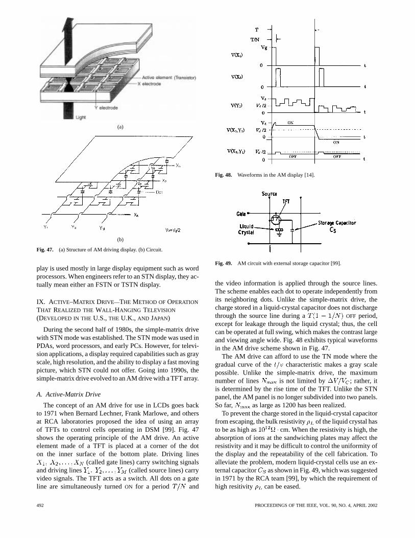
(a)
(b)
Fig. 47. (a) Structure of AM driving display. (b) Circuit.
play is used mostly in large display equipment such as wordprocessors. When engineers refer to an STN display, they ac-tually mean either an FSTN or TSTN display.
IX. A CTIVE–MATRIX DRIVE—THE METHOD OFOPERATION
THAT REALIZED THE WALL -HANGING TELEVISION
(DEVELOPED IN THEU.S.,THE U.K., AND JAPAN)
During the second half of 1980s, the simple-matrix drivewith STN mode was established. The STN mode was used inPDAs, word processors, and early PCs. However, for televi-sion applications, a display required capabilities such as grayscale, high resolution, and the ability to display a fast movingpicture, which STN could not offer. Going into 1990s, thesimple-matrix drive evolved to an AM drive with a TFT array.
A. Active-Matrix Drive
The concept of an AM drive for use in LCDs goes backto 1971 when Bernard Lechner, Frank Marlowe, and othersat RCA laboratories proposed the idea of using an arrayof TFTs to control cells operating in DSM [99]. Fig. 47shows the operating principle of the AM drive. An activeelement made of a TFT is placed at a corner of the doton the inner surface of the bottom plate. Driving lines
(called gate lines) carry switching signalsand driving lines (called source lines) carryvideo signals. The TFT acts as a switch. All dots on a gateline are simultaneously turnedON for a period and
Fig. 48. Waveforms in the AM display [14].
Fig. 49. AM circuit with external storage capacitor [99].
the video information is applied through the source lines.The scheme enables each dot to operate independently fromits neighboring dots. Unlike the simple-matrix drive, thecharge stored in a liquid-crystal capacitor does not dischargethrough the source line during a OFF period,except for leakage through the liquid crystal; thus, the cellcan be operated at full swing, which makes the contrast largeand viewing angle wide. Fig. 48 exhibits typical waveformsin the AM drive scheme shown in Fig. 47.
The AM drive can afford to use the TN mode where thegradual curve of the characteristic makes a gray scalepossible. Unlike the simple-matrix drive, the maximumnumber of lines is not limited by ; rather, itis determined by the rise time of the TFT. Unlike the STNpanel, the AM panel is no longer subdivided into two panels.So far, as large as 1200 has been realized.
To prevent the charge stored in the liquid-crystal capacitorfrom escaping, the bulk resistivity of the liquid crystal hasto be as high as cm. When the resistivity is high, theabsorption of ions at the sandwiching plates may affect theresistivity and it may be difficult to control the uniformity ofthe display and the repeatability of the cell fabrication. Toalleviate the problem, modern liquid-crystal cells use an ex-ternal capacitor as shown in Fig. 49, which was suggestedin 1971 by the RCA team [99], by which the requirement ofhigh resitivity can be eased.
492 PROCEEDINGS OF THE IEEE, VOL. 90, NO. 4, APRIL 2002
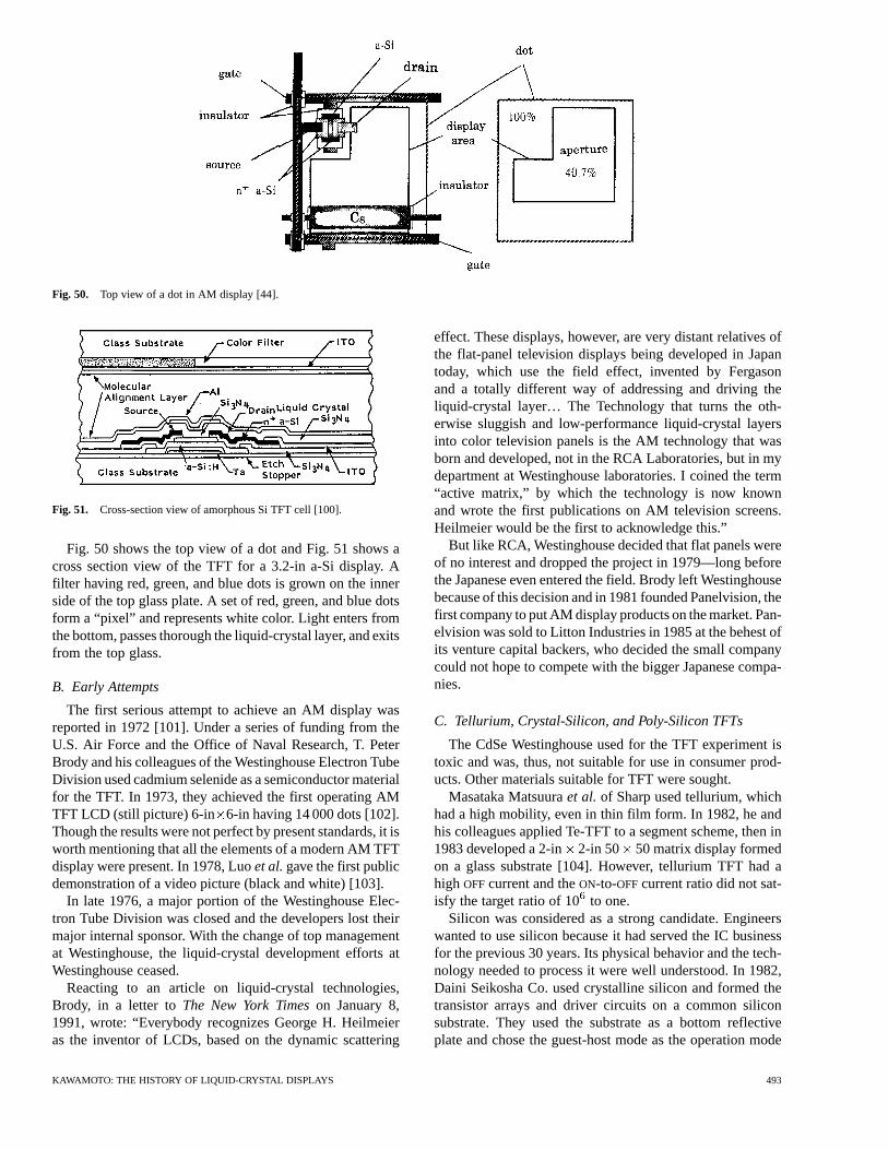
Fig. 50. Top view of a dot in AM display [44].
Fig. 51. Cross-section view of amorphous Si TFT cell [100].
Fig. 50 shows the top view of a dot and Fig. 51 shows across section view of the TFT for a 3.2-in a-Si display. Afilter having red, green, and blue dots is grown on the innerside of the top glass plate. A set of red, green, and blue dotsform a “pixel” and represents white color. Light enters fromthe bottom, passes thorough the liquid-crystal layer, and exitsfrom the top glass.
B. Early Attempts
The first serious attempt to achieve an AM display wasreported in 1972 [101]. Under a series of funding from theU.S. Air Force and the Office of Naval Research, T. PeterBrody and his colleagues of the Westinghouse Electron TubeDivision used cadmium selenide as a semiconductor materialfor the TFT. In 1973, they achieved the first operating AMTFT LCD (still picture) 6-in 6-in having 14 000 dots [102].Though the results were not perfect by present standards, it isworth mentioning that all the elements of a modern AM TFTdisplay were present. In 1978, Luoet al.gave the first publicdemonstration of a video picture (black and white) [103].
In late 1976, a major portion of the Westinghouse Elec-tron Tube Division was closed and the developers lost theirmajor internal sponsor. With the change of top managementat Westinghouse, the liquid-crystal development efforts atWestinghouse ceased.
Reacting to an article on liquid-crystal technologies,Brody, in a letter toThe New York Timeson January 8,1991, wrote: “Everybody recognizes George H. Heilmeieras the inventor of LCDs, based on the dynamic scattering
effect. These displays, however, are very distant relatives ofthe flat-panel television displays being developed in Japantoday, which use the field effect, invented by Fergasonand a totally different way of addressing and driving theliquid-crystal layer… The Technology that turns the oth-erwise sluggish and low-performance liquid-crystal layersinto color television panels is the AM technology that wasborn and developed, not in the RCA Laboratories, but in mydepartment at Westinghouse laboratories. I coined the term“active matrix,” by which the technology is now knownand wrote the first publications on AM television screens.Heilmeier would be the first to acknowledge this.”
But like RCA, Westinghouse decided that flat panels wereof no interest and dropped the project in 1979—long beforethe Japanese even entered the field. Brody left Westinghousebecause of this decision and in 1981 founded Panelvision, thefirst company to put AM display products on the market. Pan-elvision was sold to Litton Industries in 1985 at the behest ofits venture capital backers, who decided the small companycould not hope to compete with the bigger Japanese compa-nies.
C. Tellurium, Crystal-Silicon, and Poly-Silicon TFTs
The CdSe Westinghouse used for the TFT experiment istoxic and was, thus, not suitable for use in consumer prod-ucts. Other materials suitable for TFT were sought.
Masataka Matsuuraet al. of Sharp used tellurium, whichhad a high mobility, even in thin film form. In 1982, he andhis colleagues applied Te-TFT to a segment scheme, then in1983 developed a 2-in 2-in 50 50 matrix display formedon a glass substrate [104]. However, tellurium TFT had ahigh OFFcurrent and theON-to-OFFcurrent ratio did not sat-isfy the target ratio of 10to one.
Silicon was considered as a strong candidate. Engineerswanted to use silicon because it had served the IC businessfor the previous 30 years. Its physical behavior and the tech-nology needed to process it were well understood. In 1982,Daini Seikosha Co. used crystalline silicon and formed thetransistor arrays and driver circuits on a common siliconsubstrate. They used the substrate as a bottom reflectiveplate and chose the guest-host mode as the operation mode
KAWAMOTO: THE HISTORY OF LIQUID-CRYSTAL DISPLAYS 493
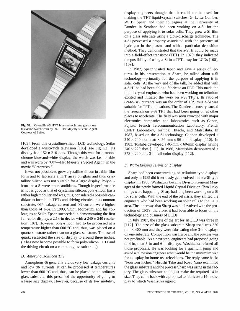
Fig. 52. Crystalline-Si-TFT blue-monochrome guest-hosttelevision watch worn by 007—Her Majesty’s Secret Agent.Courtesy of Seiko.
[105]. From this crystalline-silicon LCD technology, Seikodeveloped a wristwatch television [106] (see Fig. 52). Itsdisplay had 152 210 dots. Though this was for a mono-chrome blue-and-white display, the watch was fashionableand was worn by “007—Her Majesty’s Secret Agent” in themovie “Octopussy.”
It was not possible to grow crystalline silicon in a thin-filmform and to fabricate a TFT array on glass and thus crys-talline silicon was not suitable for a large display. Poly-sil-icon and a-Si were other candidates. Though its performanceis not as good as that of crystalline silicon, poly-silicon has arather high mobility and was, thus, considered a possible can-didate to form both TFTs and driving circuits on a commonsubstrate.OFF-leakage current andON current were higherthan those of a-Si. In 1983, Shinji Morozumi and his col-leagues at Seiko Epson succeeded in demonstrating the firstfull-color display, a 2.13-in device with a 240240 resolu-tion [107]. However, poly-silicon had to be processed at atemperature higher than 600C and, thus, was placed on aquartz substrate rather than on a glass substrate. The use ofquartz restricted the size of display to around three inches.(It has now become possible to form poly-silicon TFTs andthe driving circuit on a common glass substrate.)
D. Amorphous-Silicon TFT
Amorphous-Si generally yields very low leakage currentsand low ON currents. It can be processed at temperatureslower than 600 C and, thus, can be placed on an ordinaryglass substrate; this presented the opportunity of going toa large size display. However, because of its low mobility,
display engineers thought that it could not be used formaking the TFT liquid-crystal switches. G. L. Le Comber,W. B. Spear, and their colleagues at the University ofDundee in Scotland had been working on a-Si for thepurpose of applying it to solar cells. They grew a-Si filmon a glass substrate using a glow-discharge technique. Thea-Si possessed a property associated with the presence ofhydrogen in the plasma and with a particular depositionmethod. They demonstrated that the a-Si:H could be madeinto a field-effect transistor (FET). In 1979, they indicatedthe possibility of using a-Si in a TFT array for LCDs [108],[109].
In 1982, Spear visited Japan and gave a series of lec-tures. In his presentation at Sharp, he talked about a-Sitechnology—primarily for the purpose of applying it insolar cells. At the very end of the talk, he added that witha-Si:H he had been able to fabricate an FET. This made theliquid-crystal engineers who had been working on telluriumexcited and initiated the work on a-Si TFT’s. Its ratio ofON-to-OFF currents was on the order of 10, thus a-Si wassuitable for TFT applications. The Dundee discovery causedthe research on a-Si TFT that had been going on at otherplaces to accelerate. The field was soon crowded with majorelectronics companies and laboratories such as Canon,Fujitsu, French Telecommunication Laboratory, FrenchCNET Laboratory, Toshiba, Hitachi, and Matsushita. In1982, based on the a-Si technology, Cannon developed a240 240 dot matrix 96-mm 96-mm display [110]. In1983, Toshiba developed a 40-mm60-mm display having240 220 dots [111]. In 1986, Matsushita demonstrated a378 240 dots 3-in full-color display [112].
E. Wall-Hanging Television Display
Sharp had been concentrating on tellurium type displaysand only in 1985 did it seriously get involved in the a-Si-typedisplay. In 1986, Washizuka became Division General Man-ager of the newly formed Liquid Crystal Division. Two luckythings were happening. Sharp had long been working on a-Sifor solar cells. With the end of the oil crisis, they shifted theengineers who had been working on solar cells to the LCDarea. The other was that Sharp was not involved with the pro-duction of CRTs; therefore, it had been able to focus on thetechnology and business of LCDs.
In July 1987, the state of the art for an LCD was three in[112]. The size of the glass substrate Sharp used was 320mm 400 mm and they were fabricating nine 3-in displayson one substrate. Competition was fierce and the process wasnot profitable. As a next step, engineers had proposed goingto 4-in, then 5-in and 6-in displays. Washizuka refused allthose proposals. He was looking for a quantum jump andasked a television engineer what would be the minimum sizefor a display for home-use televisions. The reply came back:“Fourteen inches.” Hiroshi Take and Kozo Yano examinedthe glass substrate and the process Sharp was using in the fac-tory. The glass substrate could just make the required 14-insize. They came back with a proposal to fabricate a 14-in dis-play to which Washizuka agreed.
494 PROCEEDINGS OF THE IEEE, VOL. 90, NO. 4, APRIL 2002
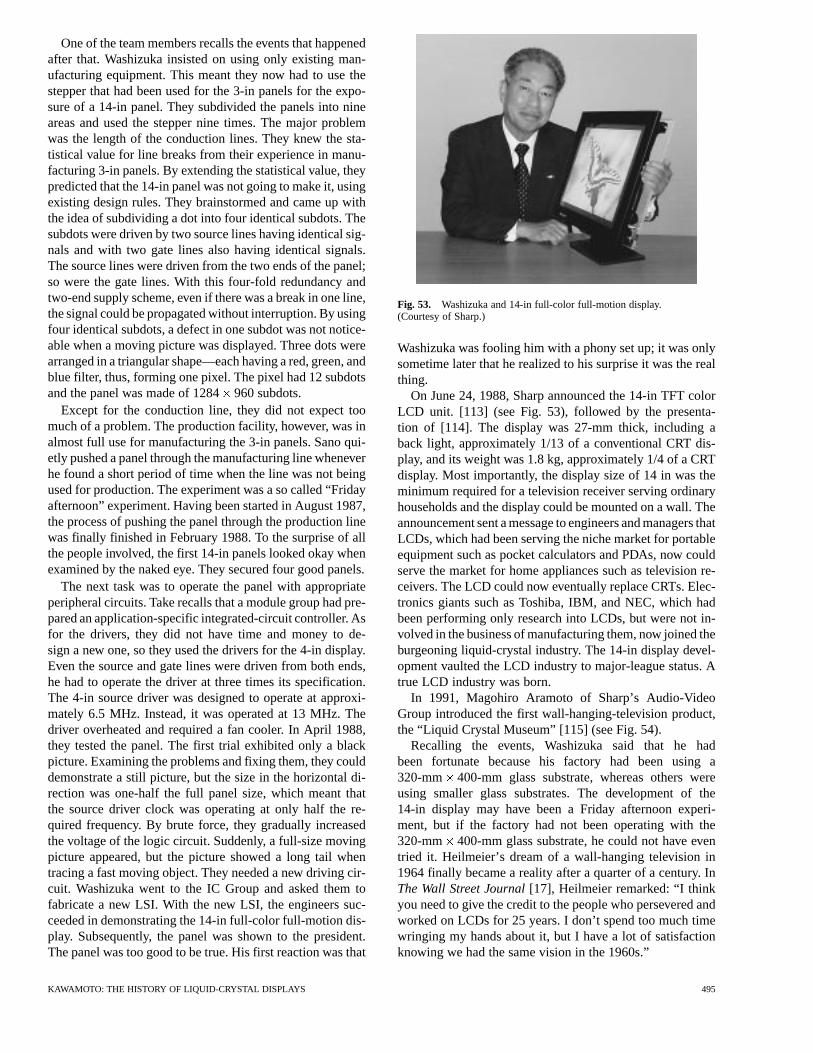
One of the team members recalls the events that happenedafter that. Washizuka insisted on using only existing man-ufacturing equipment. This meant they now had to use thestepper that had been used for the 3-in panels for the expo-sure of a 14-in panel. They subdivided the panels into nineareas and used the stepper nine times. The major problemwas the length of the conduction lines. They knew the sta-tistical value for line breaks from their experience in manu-facturing 3-in panels. By extending the statistical value, theypredicted that the 14-in panel was not going to make it, usingexisting design rules. They brainstormed and came up withthe idea of subdividing a dot into four identical subdots. Thesubdots were driven by two source lines having identical sig-nals and with two gate lines also having identical signals.The source lines were driven from the two ends of the panel;so were the gate lines. With this four-fold redundancy andtwo-end supply scheme, even if there was a break in one line,the signal could be propagated without interruption. By usingfour identical subdots, a defect in one subdot was not notice-able when a moving picture was displayed. Three dots werearranged in a triangular shape—each having a red, green, andblue filter, thus, forming one pixel. The pixel had 12 subdotsand the panel was made of 1284960 subdots.
Except for the conduction line, they did not expect toomuch of a problem. The production facility, however, was inalmost full use for manufacturing the 3-in panels. Sano qui-etly pushed a panel through the manufacturing line wheneverhe found a short period of time when the line was not beingused for production. The experiment was a so called “Fridayafternoon” experiment. Having been started in August 1987,the process of pushing the panel through the production linewas finally finished in February 1988. To the surprise of allthe people involved, the first 14-in panels looked okay whenexamined by the naked eye. They secured four good panels.
The next task was to operate the panel with appropriateperipheral circuits. Take recalls that a module group had pre-pared an application-specific integrated-circuit controller. Asfor the drivers, they did not have time and money to de-sign a new one, so they used the drivers for the 4-in display.Even the source and gate lines were driven from both ends,he had to operate the driver at three times its specification.The 4-in source driver was designed to operate at approxi-mately 6.5 MHz. Instead, it was operated at 13 MHz. Thedriver overheated and required a fan cooler. In April 1988,they tested the panel. The first trial exhibited only a blackpicture. Examining the problems and fixing them, they coulddemonstrate a still picture, but the size in the horizontal di-rection was one-half the full panel size, which meant thatthe source driver clock was operating at only half the re-quired frequency. By brute force, they gradually increasedthe voltage of the logic circuit. Suddenly, a full-size movingpicture appeared, but the picture showed a long tail whentracing a fast moving object. They needed a new driving cir-cuit. Washizuka went to the IC Group and asked them tofabricate a new LSI. With the new LSI, the engineers suc-ceeded in demonstrating the 14-in full-color full-motion dis-play. Subsequently, the panel was shown to the president.The panel was too good to be true. His first reaction was that
Fig. 53. Washizuka and 14-in full-color full-motion display.(Courtesy of Sharp.)
Washizuka was fooling him with a phony set up; it was onlysometime later that he realized to his surprise it was the realthing.
On June 24, 1988, Sharp announced the 14-in TFT colorLCD unit. [113] (see Fig. 53), followed by the presenta-tion of [114]. The display was 27-mm thick, including aback light, approximately 1/13 of a conventional CRT dis-play, and its weight was 1.8 kg, approximately 1/4 of a CRTdisplay. Most importantly, the display size of 14 in was theminimum required for a television receiver serving ordinaryhouseholds and the display could be mounted on a wall. Theannouncement sent a message to engineers and managers thatLCDs, which had been serving the niche market for portableequipment such as pocket calculators and PDAs, now couldserve the market for home appliances such as television re-ceivers. The LCD could now eventually replace CRTs. Elec-tronics giants such as Toshiba, IBM, and NEC, which hadbeen performing only research into LCDs, but were not in-volved in the business of manufacturing them, now joined theburgeoning liquid-crystal industry. The 14-in display devel-opment vaulted the LCD industry to major-league status. Atrue LCD industry was born.
In 1991, Magohiro Aramoto of Sharp’s Audio-VideoGroup introduced the first wall-hanging-television product,the “Liquid Crystal Museum” [115] (see Fig. 54).
Recalling the events, Washizuka said that he hadbeen fortunate because his factory had been using a320-mm 400-mm glass substrate, whereas others wereusing smaller glass substrates. The development of the14-in display may have been a Friday afternoon experi-ment, but if the factory had not been operating with the320-mm 400-mm glass substrate, he could not have eventried it. Heilmeier’s dream of a wall-hanging television in1964 finally became a reality after a quarter of a century. InThe Wall Street Journal[17], Heilmeier remarked: “I thinkyou need to give the credit to the people who persevered andworked on LCDs for 25 years. I don’t spend too much timewringing my hands about it, but I have a lot of satisfactionknowing we had the same vision in the 1960s.”
KAWAMOTO: THE HISTORY OF LIQUID-CRYSTAL DISPLAYS 495
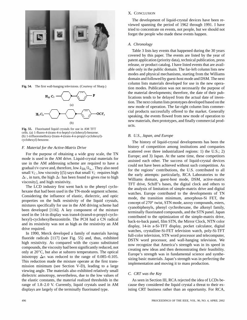
Fig. 54. The first wall-hanging televisions. (Courtesy of Sharp.)
(a)
(b)
Fig. 55. Fluorinated liquid crystals for use in AM TFTcells. (a) 1-fluoro-4-(trans-4-n-heptyl-cyclohexyl)-benzene.(b) 1-trifluoromethoxy-[trans-4-(trans-4-n-propyl-cyclohexyl)-cyclohexyl]-benzene.
F. Material for the Active-Matrix Drive
For the purpose of obtaining a wide gray scale, the TNmode is used in the AM drive. Liquid-crystal materials foruse in the AM addressing scheme are required to have agradual t/v curve and, therefore, low . They also needsmall , low viscosity [(5) says that small requires high
, in turn, the high has been found to gives rise to highviscosity], and high resistivity.
The LCD industry first went back to the phenyl cyclo-hexane that had been used in the TN-mode segment scheme.Considering the influence of elastic, dielectric, and opticproperties on the bulk resistivity of the liquid crystals,mixtures specifically for use in the AM driving scheme hadbeen developed [116]. A key component of the mixtureused in the 14-in display was trans4-(trans4-n-propyl-cyclo-hexyl)-cyclohexylbenzonitrile. The PCH had a CN radicaland its resistivity was not as high as the resistivity an AMdrive required.
In 1990, Merck developed a family of materials havingfluoride radicals [117] (see Fig. 55) and, thus, exhibitedhigh resistivity. As compared with the cyano substitutedcompounds, the viscosity had been significantly reduced, notonly at 20 C, but also at subzero temperatures. The opticalinisotropy was reduced to the range of 0.085–0.105.This reduction made the mixture operate at the first trans-mission minimum (see Section V-D), leading to a largeviewing angle. The materials also exhibited relatively smalldielectric anisotropy, nevertheless, due to the low values ofthe elastic constants, the material realized thresholds in therange of 1.8–2.0 V. Currently, liquid crystals used in AMdisplays are largely of the terminally fluorinated type.
X. CONCLUSION
The development of liquid-crystal devices have been re-viewed spanning the period of 1962 through 1991. I havetried to concentrate on events, not people, but we should notforget the people who made these events happen.
A. Chronology
Table 3 lists key events that happened during the 30 yearscovered by this paper. The events are listed by the year ofpatent application (priority data), technical publication, pressrelease, or product catalog. I have listed events that are avail-able only in the public domain. The far-left column lists newmodes and physical mechanisms, starting from the Williamsdomain and followed by guest-host mode and DSM. The nextcolumn lists materials developed for use in the new opera-tion modes. Publication was not necessarily the purpose ofthe material developments; therefore, the date of their pub-lications tends to be delayed from the actual date of inven-tion. The next column lists prototypes developed based on thenew mode of operation. The far-right column lists commer-cial products successfully offered to the market. Generallyspeaking, the events flowed from new mode of operation tonew materials, then prototypes, and finally commercial prod-ucts.
B. U.S., Japan, and Europe
The history of liquid-crystal developments has been thehistory of competition among institutions and companiesscattered over three industrialized regions: 1) the U.S.; 2)Europe; and 3) Japan. At the same time, these competitorsassisted each other. The success of liquid-crystal devicescould not have been achieved without such competition. Asfor the regions’ contributions, the U.S. contributed to allthe early attempts: particularly, RCA Laboratories to theWilliams domain, guest-host mode, DSM, active-matrixTFT drive, Schiff’s bases, the digital clock and others tothe analysis of limitation of simple-matrix drive and digitalwatches. Europe contributed to the developments of TNmode, the transition minimum, amorphous-Si FET, theconcept of 270 twist, STN mode, azoxy compounds, esters,cyanobiphenyls, phenyl cychrohexane, the alkenyl family,terminally fluorinated compounds, and the STN panel. Japancontributed to the optimization of the simple-matrix drive,back-to-back panel, film STN, the Mirror Clock, NTN colordisplay, 14-in a-Si-TFT display, pocket calculator, digitalwatches, crystalline-Si-FET television watch, poly-Si-TFTfull-color television, STN word processor and telecomputer,DSTN word processor, and wall-hanging television. Wenow recognize that America’s strength was in its speed increating new ideas and then demonstrating their feasibility.Europe’s strength was in fundamental science and synthe-sizing basic materials. Japan’s strength was in perfecting theimplementation and moving it to mass production.
C. CRT was the Key
As seen in Section III, RCA rejected the idea of LCDs be-cause they considered the liquid crystal a threat to their ex-isting CRT business rather than an opportunity. For RCA,
496 PROCEEDINGS OF THE IEEE, VOL. 90, NO. 4, APRIL 2002
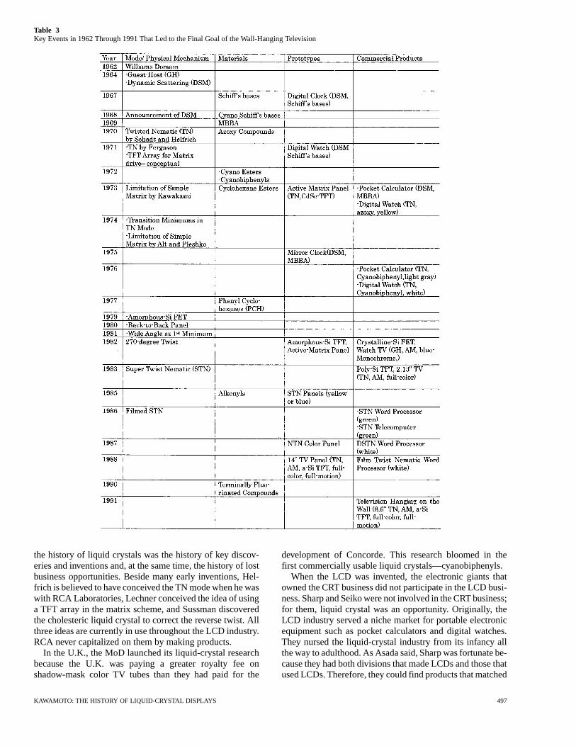
Table 3Key Events in 1962 Through 1991 That Led to the Final Goal of the Wall-Hanging Television
the history of liquid crystals was the history of key discov-eries and inventions and, at the same time, the history of lostbusiness opportunities. Beside many early inventions, Hel-frich is believed to have conceived the TN mode when he waswith RCA Laboratories, Lechner conceived the idea of usinga TFT array in the matrix scheme, and Sussman discoveredthe cholesteric liquid crystal to correct the reverse twist. Allthree ideas are currently in use throughout the LCD industry.RCA never capitalized on them by making products.
In the U.K., the MoD launched its liquid-crystal researchbecause the U.K. was paying a greater royalty fee onshadow-mask color TV tubes than they had paid for the
development of Concorde. This research bloomed in thefirst commercially usable liquid crystals—cyanobiphenyls.
When the LCD was invented, the electronic giants thatowned the CRT business did not participate in the LCD busi-ness. Sharp and Seiko were not involved in the CRT business;for them, liquid crystal was an opportunity. Originally, theLCD industry served a niche market for portable electronicequipment such as pocket calculators and digital watches.They nursed the liquid-crystal industry from its infancy allthe way to adulthood. As Asada said, Sharp was fortunate be-cause they had both divisions that made LCDs and those thatused LCDs. Therefore, they could find products that matched
KAWAMOTO: THE HISTORY OF LIQUID-CRYSTAL DISPLAYS 497
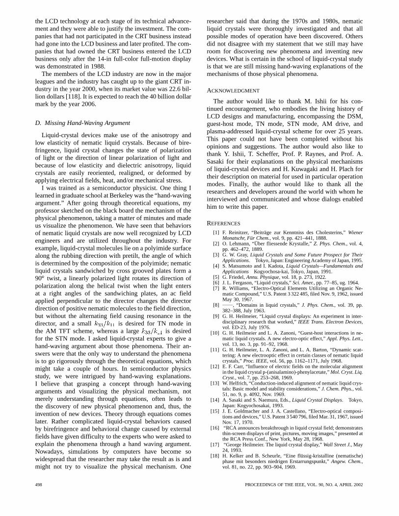
the LCD technology at each stage of its technical advance-ment and they were able to justify the investment. The com-panies that had not participated in the CRT business insteadhad gone into the LCD business and later profited. The com-panies that had owned the CRT business entered the LCDbusiness only after the 14-in full-color full-motion displaywas demonstrated in 1988.
The members of the LCD industry are now in the majorleagues and the industry has caught up to the giant CRT in-dustry in the year 2000, when its market value was 22.6 bil-lion dollars [118]. It is expected to reach the 40 billion dollarmark by the year 2006.
D. Missing Hand-Waving Argument
Liquid-crystal devices make use of the anisotropy andlow elasticity of nematic liquid crystals. Because of bire-fringence, liquid crystal changes the state of polarizationof light or the direction of linear polarization of light andbecause of low elasticity and dielectric anisotropy, liquidcrystals are easily reoriented, realigned, or deformed byapplying electrical fields, heat, and/or mechanical stress.
I was trained as a semiconductor physicist. One thing Ilearned in graduate school at Berkeley was the “hand-wavingargument.” After going through theoretical equations, myprofessor sketched on the black board the mechanism of thephysical phenomenon, taking a matter of minutes and madeus visualize the phenomenon. We have seen that behaviorsof nematic liquid crystals are now well recognized by LCDengineers and are utilized throughout the industry. Forexample, liquid-crystal molecules lie on a polyimide surfacealong the rubbing direction with pretilt, the angle of whichis determined by the composition of the polyimide; nematicliquid crystals sandwiched by cross grooved plates form a90 twist, a linearly polarized light rotates its direction ofpolarization along the helical twist when the light entersat a right angles of the sandwiching plates, an ac fieldapplied perpendicular to the director changes the directordirection of positive nematic molecules to the field direction,but without the alternating field causing resonance in thedirector, and a small is desired for TN mode inthe AM TFT scheme, whereas a large is desiredfor the STN mode. I asked liquid-crystal experts to give ahand-waving argument about those phenomena. Their an-swers were that the only way to understand the phenomenais to go rigorously through the theoretical equations, whichmight take a couple of hours. In semiconductor physicsstudy, we were intrigued by hand-waving explanations.I believe that grasping a concept through hand-wavingarguments and visualizing the physical mechanism, notmerely understanding through equations, often leads tothe discovery of new physical phenomenon and, thus, theinvention of new devices. Theory through equations comeslater. Rather complicated liquid-crystal behaviors causedby birefringence and behavioral change caused by externalfields have given difficulty to the experts who were asked toexplain the phenomena through a hand waving argument.Nowadays, simulations by computers have become sowidespread that the researcher may take the result as is andmight not try to visualize the physical mechanism. One
researcher said that during the 1970s and 1980s, nematicliquid crystals were thoroughly investigated and that allpossible modes of operation have been discovered. Othersdid not disagree with my statement that we still may haveroom for discovering new phenomena and inventing newdevices. What is certain in the school of liquid-crystal studyis that we are still missing hand-waving explanations of themechanisms of those physical phenomena.
ACKNOWLEDGMENT
The author would like to thank M. Ishii for his con-tinued encouragement, who embodies the living history ofLCD designs and manufacturing, encompassing the DSM,guest-host mode, TN mode, STN mode, AM drive, andplasma-addressed liquid-crystal scheme for over 25 years.This paper could not have been completed without hisopinions and suggestions. The author would also like tothank Y. Ishii, T. Scheffer, Prof. P. Raynes, and Prof. A.Sasaki for their explanations on the physical mechanismsof liquid-crystal devices and H. Kuwagaki and H. Plach fortheir description on material for used in particular operationmodes. Finally, the author would like to thank all theresearchers and developers around the world with whom heinterviewed and communicated and whose dialogs enabledhim to write this paper.
REFERENCES
[1] F. Reinitzer, “Beiträge zur Kenntniss des Cholesterins,”WienerMonatschr, Für Chem., vol. 9, pp. 421–441, 1888.
[2] O. Lehmann, “Über fliessende Krystalle,”Z. Phys. Chem., vol. 4,pp. 462–472, 1889.
[3] G. W. Gray,Liquid Crystals and Some Future Prospect for TheirApplications. Tokyo, Japan: Engineering Academy of Japan, 1995.
[4] S. Matsumoto and I. Kadota,Liquid Crystals—Fundamentals andApplications Kogyochosa-kai, Tokyo, Japan, 1991.
[5] G. Friedel,Annu. Physique, vol. 18, p. 273, 1922.[6] J. L. Fergason, “Liquid crystals,”Sci. Amer., pp. 77–85, ug. 1964.[7] R. Williams, “Electro-Optical Elements Utilizing an Organic Ne-
matic Compound,” U.S. Patent 3 322 485, filed Nov. 9, 1962, issuedMay 30, 1967.
[8] , “Domains in liquid crystals,”J. Phys. Chem., vol. 39, pp.382–388, July 1963.
[9] G. H. Heilmeier, “Liquid crystal displays: An experiment in inter-disciplinary research that worked,”IEEE Trans. Electron Devices,vol. ED-23, July 1976.
[10] G. H. Heilmeier and L. A. Zanoni, “Guest-host interactions in ne-matic liquid crystals. A new electro-optic effect,”Appl. Phys. Lett.,vol. 13, no. 3, pp. 91–92, 1968.
[11] G. H. Heilmeier, L. A. Zanoni, and L. A. Barton, “Dynamic scat-tering: A new electrooptic effect in certain classes of nematic liquidcrystals,”Proc. IEEE, vol. 56, pp. 1162–1171, July 1968.
[12] E. F. Carr, “Influence of electric fields on the molecular alignmentin the liquid crystal p-(anisalamino)-phenylacetate,”Mol. Cryst. Liq.Cryst., vol. 7, pp. 253–268, 1969.
[13] W. Helfrich, “Conduction-induced alignment of nematic liquid crys-tals: Basic model and stability considerations,”J. Chem. Phys., vol.51, no. 9, p. 4092, Nov. 1969.
[14] A. Sasaki and S. Naemura, Eds.,Liquid Crystal Displays. Tokyo,Japan: Kogyochosakai, 1993.
[15] J. E. Goldmacher and J. A. Castellano, “Electro-optical composi-tions and devices,” U.S. Patent 3 540 796, filed Mar. 31, 1967, issuedNov. 17, 1970.
[16] “RCA announces breakthrough in liquid crystal field; demonstratesthin-screen displays of print, pictures, moving images,” presented atthe RCA Press Conf., New York, May 28, 1968.
[17] “George Heilmeier. The liquid crystal display,”Wall Street J., May24, 1993.
[18] H. Kelker and B. Scheurle, “Eine flüssig-kristalline (nematische)phase mit besonders niedrigen Erstarrungspunkt,”Angew. Chem.,vol. 81, no. 22, pp. 903–904, 1969.
498 PROCEEDINGS OF THE IEEE, VOL. 90, NO. 4, APRIL 2002
[19] P. Weimer, “Switching circuits,” U.S. Patent 3 191 061, filed May1962, issued June 22, 1965.
[20] Y. Suzuki, M. Hirasawa, and K. Odagawa, “Clocked CMOS cal-culator circuitry,” inProc. Int. Solid State Circuit Conf., 1973, pp.58–59.
[21] “The world-first computer on substrate; operates for 100 hours witha single AA-size dry battery,” Sharp Corp. News Release, May 15,1973.
[22] S. Mito and T. Wada, “Application of liquid crystal to COS (cal-culator on substrate) system electronic calculator,” inProc. 5th Int.Liquid Crystal Conf., 1974, pp. 247–248.
[23] W. Helfrich and M. Schadt, “Optical device,” Swiss Patent 532261,filed Dec. 4, 1970, issued Feb. 15, 1972.
[24] M. Schadt and W. Helfrich, “Voltage-dependent optical activity of atwisted nematic liquid crystal,”Appl. Phys. Lett., vol. 18, no. 4, pp.127–128, Feb. 1971.
[25] H. Zocher,Physik. Chem., vol. 132, p. 295, 1928.[26] C. R. Chatelain,Acad. Sci., vol. 213, p. 875, 1941.[27] F. M. Leslie, “Distortion of orientation patterns in liquid crystals by
a magnetic field ,” inProc. 3rd Int. Liquid Crystal Conf., Berlin,Germany, Aug. 1970, p. 104.
[28] C. Mauguin,Bull. Soc. Franc. Mineral, vol. 34, pp. 71–117, 1911.[29] H. de Vries,Acta Cryst., vol. 4, p. 219, 1951.[30] J. F. Dryer, “A liquid crystal device for rotating of polarized light,”
in Proc. 3rd Int. Liquid Crystal Conf., Berlin, Germany, Aug. 1970,p. 25.
[31] G. H. Heilmeier, L. A. Zanoni, and J. E. Goldmacher,Liquid Crystalsand Ordered Fluids, J. F. Johnson and R. S. Porter, Eds. New York:Plenum, 1970.
[32] J. A. Castellano, “Electro-optic light modulator,” U.S. Patent3 597 044, filed Sept. 3, 1968, Aug. 3, 1971.
[33] A. Boller, H. Scherrer, M. Schadt, and P. Wild, “Low elec-trooptic threshold in new liquid crystals,”Proc. IEEE, vol. 60, pp.1002–1003, Aug. 1972.
[34] S. L. Arora, J. L. Fergason, and A. Saupe, “Two liquid crystal phaseswith nematic morphology in laterally substituted phenylenediaminederivatives,” inProc. 2nd Int. Liquid Crystal Conf., Aug. 1968, pp.563–577.
[35] J. L. Fergason, T. R. Taylor, and T. B. Harsch, “Liquid crystals andtheir applications,”electro technol., pp. 41–50, Jan. 1970.
[36] J. L. Fergason, “Display devices utilizing liquid crystal light mod-ulation,” U.S. Patent 3 731 986, filed Apr. 22, 1971, issued May 8,1973.
[37] , “Liquid-crystal non-linear light modulators using electric andmagnetic fields,” U.S. Patent 3 918 796, filed Jan. 24, 1973, issuedNov. 11, 1975.
[38] J. L. Fergason and T. B. Harsch, “Reflective system for liquid crystaldisplays,” U.S. Patent 3 881 809, filed May 25, 1973, issued May 6,1975.
[39] J. L. Fergason and D. E. Werth, “Liquid crystal display assembly,”U.S. Patent 3 963 324, filed Sept. 10, 1973, issued June 15, 1976.
[40] J. L. Fergason, “Gasket for liquid crystal light shutters,” U.S. Patent3 853 392, filed Sept. 13, 1973, Dec. 10, 1974.
[41] , “Liquid-crystal mixtures for use in liquid-crystal displays,”U.S. Patent 3 960 749, filed Jan. 23, 1974, issued June 1, 1976.
[42] C. H. Gooch and H. A. Tarry, “Optical characteristics of twisted ne-matic liquid-crystal films,”Electron. Lett., vol. 10, no. 1, pp. 2–3,Jan. 1974.
[43] , “The optical properties of twisted nematic liquid crystal struc-tures with twist angle equal or less than 90,” J. Phys. D. Appl. Phys.,vol. 8, pp. 1575–1584, 1975.
[44] T. Yamazaki, H. Kawakami, and H. Hori,Color TFT Liquid CrystalDisplays. Tokyo, Japan: SEMI, 1994.
[45] T. J. Scheffer, “Supertwisted-nematic LCDs,” inSociety for Infor-mation Display Seminar Lecture Notes, vol. M-12, 2000.
[46] L. Pohl, G. Weber, R. Eidenschink, G. Baur, and W. Fehrenbach,Appl. Phys. Lett., vol. 38, no. 7, pp. 497–499, Apr. 1981.
[47] B. W. Berreman, “Solid surface shape and the alignment of an ad-jacent nematic liquid crystal,”Phys. Rev. Lett., vol. 28, no. 26, pp.1683–1686, 1972.
[48] E. S. Lee, Y. Saito, and T. Uchida, “Detailed morphology of rubbedalignment layers and surface anchoring of liquid crystals,” inProc.12th Int. Display Research Conf., Hiroshima, Japan, Oct. 1992, pp.595–598.
[49] S. Ishihara, H. Wakemoto, K. Nakazima, and Y. Matsuo, “The effectof rubbed polymer films on the liquid crystal alignment,”Liq. Cryst.,vol. 4, no. 6, pp. 669–675, 1989.
[50] S. Ishihara, “Research on the alignment control of nematic liquidcrystals,” Ph.D. dissertation, Osaka Prefecture Univ., Osaka, Japan,2000.
[51] Y. Ishii, private communication, 2000.[52] H. J. Deutscher, W. Weissflog, D. Demus, and G. Petzl, “Kristallin-
Flüssige Nematische Verbindungen,” German Patent 86 269, filedJune 15, 1970, issued Dec. 5, 1971.
[53] H. Kelker, B. Scheurle, H. Hatz, and W. Bartsch, “Liquid crystallinephase having particulary low freezing points,”Angew. Chem. Int.Ed., vol. 9, no. 12, pp. 962–963, 1970.
[54] R. Steinstrasser and L. Pohl, “Nematische systeme IV: Niedrigschmelzende p-Alkyl-p’-Alkoxy- und p-Alkyl-p’-Alkoxy-Azoxy-benzole,”Tetrahedron Lett., no. 22, pp. 1921–1924, 1971.
[55] E. P. Raynes, “Twisted nematic liquid-crystal electro-optic deviceswith areas of reverse twist,”Electron. Lett., vol. 9, no. 5, Mar. 1973.
[56] A. Sussman, “Electro-optic liquid crystal devices: Principles and ap-plications,”IEEE Trans. Parts, Hybrids, Packaging, vol. PHP-8, pp.24–37, Dec. 1972.
[57] E. P. Raynes, “Improved constant uniformity in twisted nematicliquid-crystal electro optic display devices,”Electron. Lett., vol. 10,no. 9, May 1974.
[58] , “Liquid crystal devices,” U.K. Patent 1 472 247, filed Feb. 21,1974, issued May 4, 1977.
[59] , “Optically active additives in twisted nematic devices,”Rev.Phys. Appl., vol. 10, pp. 117–120, May 1975.
[60] G. W. Gray, K. J. Harrison, and J. A. Nash, “New family of ne-matic liquid crystals for displays,”Electron. Lett., vol. 9, no. 6, pp.130–131, Feb. 1973.
[61] A. Ashford, J. Constant, J. Kirton, and E. P. Raynes, “Elecro-opticperformance of a new room-temperature nematic liquid crystal,”Electron. Lett., vol. 9, no. 5, pp. 118–120, Mar. 1973.
[62] D. Hume, P. Raynes, and K. J. Harrison, “Eutectic mixtures ofnematic 4’-substituted 4-cyanobiphenyls,”J. Chem. Soc. Chem.Commun., pp. 98–98, 1974.
[63] “Ultra thin 7 mm pocket calculator EL-8125 and EL-8025 (light graybackground and high contrast black numerals),” Sharp Corp. NewsRelease, Nov. 11, 1976.
[64] Seiko digital watch catalog, Nov. 1976.[65] H. J. Deutscher, F. Kuschel, H. Schubert, and D. Demus, “Nema-
tische Flüssig-Kristalline Substanzen,” German Patent 105 701, filedJuly 2, 1973, issued May 5, 1974.
[66] V. R. Eidenschink, D. Erdman, J. Krause, and L. Pohl, “Sub-stituted phenylcyclohexanes—A new class of liquid-crystallinecompounds,”Angew. Chem. English Edition, vol. 16, no. 2, p. 100,1977.
[67] L. Pohl, R. Eidenschink, G. Krause, and D. Erdmann, “Physicalproperties of nematic phenylcyclohexanes, a new class of lowmelting liquid crystals with positive dielectric anisotropy,”Phys.Lett., vol. 60A, no. 5, pp. 421–423, Mar. 1977.
[68] “Orient magic clock; Time jumps out of the mirror,” Orient Corpo-ration News Release, 1975.
[69] S. Shimura, “Electronics past, no. 15, liquid crystal displays,”Mu-Alpha, pp. 104–108, Autumn 1990.
[70] A. Sasaki, Ed.,Liquid Crystal Bases and Applications. Kyoto,Japan: Ohm, 1979.
[71] , private communication, 2000.[72] “Quartz oscillator digital wrist watch (liquid crystal display) seiko
quartz LC V.F.A.,” Seiko News Release, Sept. 1973.[73] H. Kawakami, “Method of driving liquid crystal matrix display de-
vice,” Priority Data Oct. 19, 1973; U.S. Patent 3 976 362, Oct. 15,1974.
[74] P. M. Alt and P. Pleshko, “Scanning limitations of liquid-crystal dis-plays,”IEEE Trans. Electron Devices, vol. ED-21, pp. 146–155, Feb.1974.
[75] D. W. Berreman, “Optics in smoothly varying anisotropic planarstructures: Application to liquid-crystal twist cells,”J. Opt. Soc.Amer., vol. 63, no. 11, pp. 1374–1380, 1973.
[76] M. Schadt and P. R. Gerber, “Class specific physical properties ofliquid crystals and correlations with molecular structure and staticelectrooptical performance in twisted cells,”Z. Naturforsch, vol.37a, pp. 165–178, 1982.
[77] L. Pohl, B. Scheuble, and G. Weber, “Multiplexible liquid crystallinebroad range systems,”Mol. Cryst. Liq. Cryst., vol. 97, pp. 277–286,1983.
[78] C. M. Waters and E. P. Raynes, “Liquid crystal devices,” PriorityData June 29, 1962; U.K. Patent 2 123 163, Dec. 18, 1985.
[79] C. M. Waters, V. Brimmell, and E. P. Raynes, “Highly multiplexabledyed liquid crystal displays,” inProc. 3rd Int. Display Conf., Kobe,Japan, 1983, pp. 396–399.
[80] , “Highly multiplexable dyed LCDs,”Proc. SID, vol. 25, no. 4,pp. 261–264, 1984.
KAWAMOTO: THE HISTORY OF LIQUID-CRYSTAL DISPLAYS 499
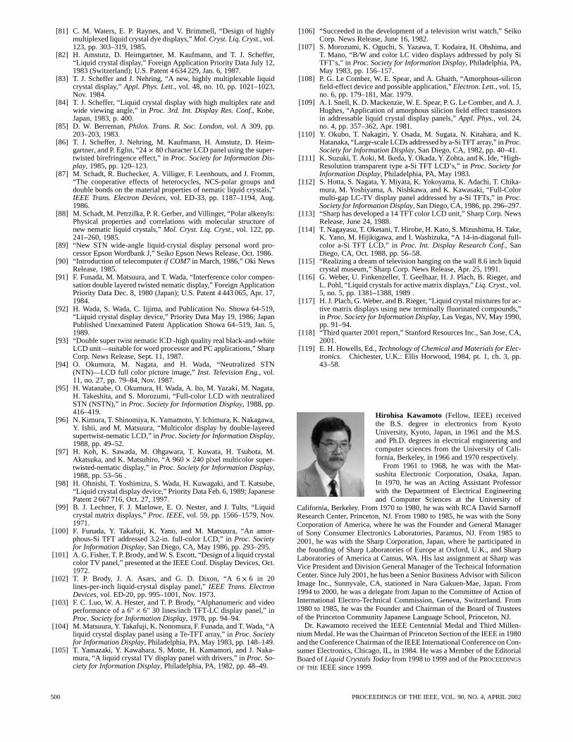
[81] C. M. Waters, E. P. Raynes, and V. Brimmell, “Design of highlymultiplexed liquid crystal dye displays,”Mol. Cryst. Liq. Cryst., vol.123, pp. 303–319, 1985.
[82] H. Amstutz, D. Heimgartner, M. Kaufmann, and T. J. Scheffer,“Liquid crystal display,” Foreign Application Priority Data July 12,1983 (Switzerland); U.S. Patent 4 634 229, Jan. 6, 1987.
[83] T. J. Scheffer and J. Nehring, “A new, highly multiplexable liquidcrystal display,”Appl. Phys. Lett., vol. 48, no. 10, pp. 1021–1023,Nov. 1984.
[84] T. J. Scheffer, “Liquid crystal display with high multiplex rate andwide viewing angle,” inProc. 3rd. Int. Display Res. Conf., Kobe,Japan, 1983, p. 400.
[85] D. W. Berreman,Philos. Trans. R. Soc. London, vol. A 309, pp.203–203, 1983.
[86] T. J. Scheffer, J. Nehring, M. Kaufmann, H. Amstutz, D. Heim-gartner, and P. Eglin, “24� 80 character LCD panel using the super-twisted birefringence effect,” inProc. Society for Information Dis-play, 1985, pp. 120–123.
[87] M. Schadt, R. Buchecker, A. Villiger, F. Leenhouts, and J. Fromm,“The cooperative effects of heterocycles, NCS-polar groups anddouble bonds on the material properties of nematic liquid crystals,”IEEE Trans. Electron Devices, vol. ED-33, pp. 1187–1194, Aug.1986.
[88] M. Schadt, M. Petrzilka, P. R. Gerber, and Villinger, “Polar alkenyls:Physical properties and correlations with molecular structure ofnew nematic liquid crystals,”Mol. Cryst. Liq. Cryst., vol. 122, pp.241–260, 1985.
[89] “New STN wide-angle liquid-crystal display personal word pro-cessor Epson Wordbank J,” Seiko Epson News Release, Oct. 1986.
[90] “Introduction of telecomputerif COM7 in March, 1986,” Oki NewsRelease, 1985.
[91] F. Funada, M. Matsuura, and T. Wada, “Interference color compen-sation double layered twisted nematic display,” Foreign ApplicationPriority Data Dec. 8, 1980 (Japan); U.S. Patent 4 443 065, Apr. 17,1984.
[92] H. Wada, S. Wada, C. Iijima, and Publication No. Showa 64-519,“Liquid crystal display device,” Priority Data May 19, 1986; JapanPublished Unexamined Patent Application Showa 64–519, Jan. 5,1989.
[93] “Double super twist nematic lCD -high quality real black-and-whiteLCD unit—suitable for word processor and PC applications,” SharpCorp. News Release, Sept. 11, 1987.
[94] O. Okumura, M. Nagata, and H. Wada, “Neutralized STN(NTN)—LCD full color picture image,”Inst. Television Eng., vol.11, no. 27, pp. 79–84, Nov. 1987.
[95] H. Watanabe, O. Okumura, H. Wada, A. Ito, M. Yazaki, M. Nagata,H. Takeshita, and S. Morozumi, “Full-color LCD with neutralizedSTN (NSTN),” inProc. Society for Information Display, 1988, pp.416–419.
[96] N. Kimura, T. Shinomiya, K. Yamamoto, Y. Ichimura, K. Nakagawa,Y. Ishii, and M. Matsuura, “Multicolor display by double-layeredsupertwist-nematic LCD,” inProc. Society for Information Display,1988, pp. 49–52.
[97] H. Koh, K. Sawada, M. Ohgawara, T. Kuwata, H. Tsubota, M.Akatsuka, and K. Matsuhiro, “A 960� 240 pixel multicolor super-twisted-nematic display,” inProc. Society for Information Display,1988, pp. 53–56 .
[98] H. Ohnishi, T. Yoshimizu, S. Wada, H. Kuwagaki, and T. Katsube,“Liquid crystal display device,” Priority Data Feb. 6, 1989; JapanesePatent 2 667 716, Oct. 27, 1997.
[99] B. J. Lechner, F. J. Marlowe, E. O. Nester, and J. Tults, “Liquidcrystal matrix displays,”Proc. IEEE, vol. 59, pp. 1566–1579, Nov.1971.
[100] F. Funada, Y. Takafuji, K. Yano, and M. Matsuura, “An amor-phous-Si TFT addressed 3.2-in. full-color LCD,” inProc. Societyfor Information Display, San Diego, CA, May 1986, pp. 293–295.
[101] A. G. Fisher, T. P. Brody, and W. S. Escott, “Design of a liquid crystalcolor TV panel,” presented at the IEEE Conf. Display Devices, Oct.1972.
[102] T. P. Brody, J. A. Asars, and G. D. Dixon, “A 6� 6 in 20lines-per-inch liquid-crystal display panel,”IEEE Trans. ElectronDevices, vol. ED-20, pp. 995–1001, Nov. 1973.
[103] F. C. Luo, W. A. Hester, and T. P. Brody, “Alphanumeric and videoperformance of a 6"� 6" 30 lines/inch TFT-LC display panel,” inProc. Society for Information Display, 1978, pp. 94–94.
[104] M. Matsuura, Y. Takafuji, K. Nonomura, F. Funada, and T. Wada, “Aliquid crystal display panel using a Te-TFT array,” inProc. Societyfor Information Display, Philadelphia, PA, May 1983, pp. 148–149.
[105] T. Yamazaki, Y. Kawahara, S. Motte, H. Kamamori, and J. Naka-mura, “A liquid crystal TV display panel with drivers,” inProc. So-ciety for Information Display, Philadelphia, PA, 1982, pp. 48–49.
[106] “Succeeded in the development of a television wrist watch,” SeikoCorp. News Release, June 16, 1982.
[107] S. Morozumi, K. Oguchi, S. Yazawa, T. Kodaira, H. Ohshima, andT. Mano, “B/W and color LC video displays addressed by poly SiTFT’s,” in Proc. Society for Information Display, Philadelphia, PA,May 1983, pp. 156–157.
[108] P. G. Le Comber, W. E. Spear, and A. Ghaith, “Amorphous-siliconfield-effect device and possible application,”Electron. Lett., vol. 15,no. 6, pp. 179–181, Mar. 1979.
[109] A. I. Snell, K. D. Mackenzie, W. E. Spear, P. G. Le Comber, and A. J.Hughes, “Application of amorphous silicion field effect transistorsin addressable liquid crystal display panels,”Appl. Phys., vol. 24,no. 4, pp. 357–362, Apr. 1981.
[110] Y. Okubo, T. Nakagiri, Y. Osada, M. Sugata, N. Kitahara, and K.Hatanaka, “Large-scale LCDs addressed by a-Si TFT array,” inProc.Society for Information Display, San Diego, CA, 1982, pp. 40–41.
[111] K. Suzuki, T. Aoki, M. Ikeda, Y. Okada, Y. Zohta, and K. Ide, “High-Resolution transparent type a-Si TFT LCD’s,” inProc. Society forInformation Display, Philadelphia, PA, May 1983.
[112] S. Hotta, S. Nagata, Y. Miyata, K. Yokoyama, K. Adachi, T. Chika-mura, M. Yoshiyama, A. Nishkawa, and K. Kawasaki, “Full-Colormulti-gap LC-TV display panel addressed by a-Si TFTs,” inProc.Society for Information Display, San Diego, CA, 1986, pp. 296–297.
[113] “Sharp has developed a 14 TFT color LCD unit,” Sharp Corp. NewsRelease, June 24, 1988.
[114] T. Nagayasu, T. Oketani, T. Hirobe, H. Kato, S. Mizushima, H. Take,K. Yano, M. Hijikigawa, and I. Washizuka, “A 14-in-diagonal full-color a-Si TFT LCD,” inProc. Int. Display Research Conf., SanDiego, CA, Oct. 1988, pp. 56–58.
[115] “Realizing a dream of television hanging on the wall 8.6 inch liquidcrystal museum,” Sharp Corp. News Release, Apr. 25, 1991.
[116] G. Weber, U. Finkenzeller, T. Geelhaar, H. J. Plach, B. Rieger, andL. Pohl, “Liquid crystals for active matrix displays,”Liq. Cryst., vol.5, no. 5, pp. 1381–1388, 1989 .
[117] H. J. Plach, G. Weber, and B. Rieger, “Liquid crystal mixtures for ac-tive matrix displays using new terminally fluorinated compounds,”in Proc. Society for Information Display, Las Vegas, NV, May 1990,pp. 91–94.
[118] “Third quarter 2001 report,” Stanford Resources Inc., San Jose, CA,2001.
[119] E. H. Howells, Ed.,Technology of Chemical and Materials for Elec-tronics. Chichester, U.K.: Ellis Horwood, 1984, pt. 1, ch. 3, pp.43–58.
Hirohisa Kawamoto (Fellow, IEEE) receivedthe B.S. degree in electronics from KyotoUniversity, Kyoto, Japan, in 1961 and the M.S.and Ph.D. degrees in electrical engineering andcomputer sciences from the University of Cali-fornia, Berkeley, in 1966 and 1970 respectively.
From 1961 to 1968, he was with the Mat-sushita Electronic Corporation, Osaka, Japan.In 1970, he was an Acting Assistant Professorwith the Department of Electrical Engineeringand Computer Sciences at the University of
California, Berkeley. From 1970 to 1980, he was with RCA David SarnoffResearch Center, Princeton, NJ. From 1980 to 1985, he was with the SonyCorporation of America, where he was the Founder and General Managerof Sony Consumer Electronics Laboratories, Paramus, NJ. From 1985 to2001, he was with the Sharp Corporation, Japan, where he participated inthe founding of Sharp Laboratories of Europe at Oxford, U.K., and SharpLaboratories of America at Camus, WA. His last assignment at Sharp wasVice President and Division General Manager of the Technical InformationCenter. Since July 2001, he has been a Senior Business Advisor with SiliconImage Inc., Sunnyvale, CA, stationed in Nara Gakuen-Mae, Japan. From1994 to 2000, he was a delegate from Japan to the Committee of Action ofInternational Electro-Technical Commission, Geneva, Switzerland. From1980 to 1985, he was the Founder and Chairman of the Board of Trusteesof the Princeton Community Japanese Language School, Princeton, NJ.
Dr. Kawamoto received the IEEE Centennial Medal and Third Millen-nium Medal. He was the Chairman of Princeton Section of the IEEE in 1980and the Conference Chairman of the IEEE International Conference on Con-sumer Electronics, Chicago, IL, in 1984. He was a Member of the EditorialBoard ofLiquid Crystals Todayfrom 1998 to 1999 and of the PROCEEDINGS
OF THE IEEE since 1999.
500 PROCEEDINGS OF THE IEEE, VOL. 90, NO. 4, APRIL 2002