the - iaria journals · thomas michael bohnert, zurich university of applied sciences, switzerland...
TRANSCRIPT


The International Journal on Advances in Internet Technology is published by IARIA.
ISSN: 1942-2652
journals site: http://www.iariajournals.org
contact: [email protected]
Responsibility for the contents rests upon the authors and not upon IARIA, nor on IARIA volunteers,
staff, or contractors.
IARIA is the owner of the publication and of editorial aspects. IARIA reserves the right to update the
content for quality improvements.
Abstracting is permitted with credit to the source. Libraries are permitted to photocopy or print,
providing the reference is mentioned and that the resulting material is made available at no cost.
Reference should mention:
International Journal on Advances in Internet Technology, issn 1942-2652
vol. 5, no. 1 & 2, year 2012, http://www.iariajournals.org/internet_technology/
The copyright for each included paper belongs to the authors. Republishing of same material, by authors
or persons or organizations, is not allowed. Reprint rights can be granted by IARIA or by the authors, and
must include proper reference.
Reference to an article in the journal is as follows:
<Author list>, “<Article title>”
International Journal on Advances in Internet Technology, issn 1942-2652
vol. 5, no. 1 & 2, year 2012, <start page>:<end page> , http://www.iariajournals.org/internet_technology/
IARIA journals are made available for free, proving the appropriate references are made when their
content is used.
Sponsored by IARIA
www.iaria.org
Copyright © 2012 IARIA

International Journal on Advances in Internet Technology
Volume 5, Number 1 & 2, 2012
Editor-in-Chief
Petre Dini, Concordia University, Canada / China Space Agency Center, China
Editorial Advisory Board
Lasse Berntzen, Vestfold University College - Tonsberg, NorwayMichel Diaz, LAAS, FranceEvangelos Kranakis, Carleton University, CanadaBertrand Mathieu, Orange-ftgroup, France
Editorial Board
Jemal Abawajy, Deakin University, Australia
Chang-Jun Ahn, School of Engineering, Chiba University, Japan
Sultan Aljahdali, Taif University, Saudi Arabia
Shadi Aljawarneh, Isra University, Jordan
Giner Alor Hernández, Instituto Tecnológico de Orizaba, Mexico
Onur Alparslan, Osaka University, Japan
Feda Alshahwan, The University of Surrey, UK
Ioannis Anagnostopoulos, University of Central Greece - Lamia, Greece
M.Ali Aydin, Istanbul University, Turkey
Gilbert Babin, HEC Montréal, Canada
Faouzi Bader, CTTC, Spain
Kambiz Badie, Research Institute for ICT & University of Tehran, Iran
Jasmina Baraković Husić, BH Telecom, Bosnia and Herzegovina
Ataul Bari, University of Western Ontario, Canada
Javier Barria, Imperial College London, UK
Shlomo Berkovsky, NICTA, Australia
Lasse Berntzen, Vestfold University College - Tønsberg, Norway
Nik Bessis, University of Derby, UK
Jun Bi, Tsinghua University, China
Marco Block-Berlitz, Freie Universität Berlin, Germany
Christophe Bobda, University of Arkansas, USA
Alessandro Bogliolo, DiSBeF-STI University of Urbino, Italy
Thomas Michael Bohnert, Zurich University of Applied Sciences, Switzerland
Eugen Borcoci, University "Politehnica"of Bucharest, Romania
Luis Borges Gouveia, University Fernando Pessoa, Portugal
Fernando Boronat Seguí, Universidad Politécnica de Valencia, Spain
Mahmoud Boufaida, Mentouri University - Constantine, Algeria
Christos Bouras, University of Patras, Greece
Agnieszka Brachman, Institute of Informatics, Silesian University of Technology, Gliwice, Poland

Thierry Brouard, Université François Rabelais de Tours, France
Dumitru Dan Burdescu, University of Craiova, Romania
Carlos T. Calafate, Universitat Politècnica de València, Spain
Christian Callegari, University of Pisa, Italy
Juan-Vicente Capella-Hernández, Universitat Politècnica de València, Spain
Miriam A. M. Capretz, The University of Western Ontario, Canada
Ajay Chakravarthy, University of Southampton IT Innovation Centre, UK
Chin-Chen Chang, Feng Chia University, Taiwan
Ruay-Shiung Chang, National Dong Hwa University, Taiwan
Tzung-Shi Chen, National University of Tainan, Taiwan
Xi Chen, University of Washington, USA
Dickson Chiu, Dickson Computer Systems, Hong Kong
IlKwon Cho, National Information Society Agency, South Korea
Andrzej Chydzinski, Silesian University of Technology, Poland
Noël Crespi, Telecom SudParis, France
Antonio Cuadra-Sanchez, Indra, Spain
Javier Cubo, University of Malaga, Spain
Alfredo Cuzzocrea, University of Calabria, Italy
Jan de Meer, smartspace®lab.eu GmbH, Germany
Sagarmay Deb, Central Queensland University, Australia
Javier Del Ser, Tecnalia Research & Innovation, Spain
Philipe Devienne, LIFL - Université Lille 1 - CNRS, France
Kamil Dimililer, Near East Universiy, Cyprus
Martin Dobler, Vorarlberg University of Applied Sciences, Austria
Eugeni Dodonov, Intel Corporation- Brazil, Brazil
Jean-Michel Dricot, Université Libre de Bruxelles, Belgium
Matthias Ehmann, Universität Bayreuth, Germany
Tarek El-Bawab, Jackson State University, USA
Nashwa Mamdouh El-Bendary, Arab Academy for Science, Technology, and Maritime Transport, Egypt
Mohamed Dafir El Kettani, ENSIAS - Université Mohammed V-Souissi, Morocco
Armando Ferro, University of the Basque Country (UPV/EHU), Spain
Anders Fongen, Norwegian Defence Research Establishment, Norway
Giancarlo Fortino, University of Calabria, Italy
Kary Främling, Aalto University, Finland
Steffen Fries, Siemens AG, Corporate Technology - Munich, Germany
Ivan Ganchev, University of Limerick, Ireland
Shang Gao, Zhongnan University of Economics and Law, China
Kamini Garg, University of Applied Sciences Southern Switzerland, Lugano, Switzerland
Rosario Giuseppe Garroppo, Dipartimento Ingegneria dell'informazione - Università di Pisa, Italy
Thierry Gayraud, LAAS-CNRS / Université de Toulouse / Université Paul Sabatier, France
Christos K. Georgiadis, University of Macedonia, Greece
Katja Gilly, Universidad Miguel Hernandez, Spain
Feliz Gouveia, Universidade Fernando Pessoa - Porto, Portugal
Kannan Govindan, Crash Avoidance Metrics Partnership (CAMP), USA
Bill Grosky, University of Michigan-Dearborn, USA
Vic Grout, Glyndŵr University, UK

Jason Gu, Singapore University of Technology and Design, Singapore
Christophe Guéret, Vrije Universiteit Amsterdam, Nederlands
Frederic Guidec, IRISA-UBS, Université de Bretagne-Sud, France
Bin Guo, Northwestern Polytechnical University, China
Gerhard Hancke, Royal Holloway / University of London, UK
Arthur Herzog, Technische Universität Darmstadt, Germany
Rattikorn Hewett, Whitacre College of Engineering, Texas Tech University, USA
Nicolas Hidalgo, Yahoo! Research Latin America, France
Quang Hieu Vu, EBTIC, Khalifa University, Arab Emirates
Hiroaki Higaki, Tokyo Denki University, Japan
Eva Hladká, Masaryk University, Czech Republic
Dong Ho Cho, Korea Advanced Institute of Science and Technology (KAIST), Korea
Anna Hristoskova, Ghent University - IBBT, Belgium
Ching-Hsien (Robert) Hsu, Chung Hua University, Taiwan
Christian Hübsch, Institute of Telematics, Karlsruhe Institute of Technology (KIT), Germany
Chi Hung, Tsinghua University, China
Edward Hung, Hong Kong Polytechnic University, Hong Kong
Linda A. Jackson, Michigan State University, USA
Raj Jain, Washington University in St. Louis , USA
Edward Jaser, Princess Sumaya University for Technology - Amman, Jordan
Yasushi Kambayashi, Nippon Institute of Technology, Japan
Georgios Kambourakis, University of the Aegean, Greece
Atsushi Kanai, Hosei University, Japan
Henrik Karstoft , Aarhus University, Denmark
Dimitrios Katsaros, University of Thessaly, Greece
Ayad ali Keshlaf, Newcastle University, UK
Changick Kim, Korea Advanced Institute of Science and Technology, Daejeon, South Korea
Reinhard Klemm, Avaya Labs Research, USA
Samad Kolahi, Unitec Institute Of Technology, New Zealand
Dmitry Korzun, Petrozavodsk State University, Russia / Aalto University, Finland
Evangelos Kranakis, Carleton University - Ottawa, Canada
Slawomir Kuklinski, Warsaw University of Technology, Poland
Andrew Kusiak, The University of Iowa, USA
Mikel Larrea, University of the Basque Country UPV/EHU, Spain
Frédéric Le Mouël, University of Lyon, INSA Lyon / INRIA, France
Nicolas Le Sommer, Université Européenne de Bretagne, France
Juong-Sik Lee, Nokia Research Center, USA
Wolfgang Leister, Norsk Regnesentral ( Norwegian Computing Center ), Norway
Clement Leung, Hong Kong Baptist University, Hong Kong
Man-Sze Li , IC Focus, UK
Longzhuang Li, Texas A&M University-Corpus Christi, USA
Yaohang Li, Old Dominion University, USA
Jong Chern Lim, University College Dublin, Ireland
Lu Liu, University of Derby, UK
Damon Shing-Min Liu, National Chung Cheng University, Taiwan
Michael D. Logothetis, University of Patras, Greece

Malamati Louta, University of Western Macedonia, Greece
Maode Ma, Nanyang Technological University, Singapore
Elsa María Macías López, University of Las Palmas de Gran Canaria, Spain
Olaf Maennel, Loughborough University, UK
Zoubir Mammeri, IRIT - Paul Sabatier University - Toulouse, France
Yong Man, KAIST (Korea advanced Institute of Science and Technology), South Korea
Sathiamoorthy Manoharan, University of Auckland, New Zealand
Chengying Mao, Jiangxi University of Finance and Economics, China
Brandeis H. Marshall, Purdue University, USA
Sergio Martín Gutiérrez, UNED-Spanish University for Distance Education, Spain
Constandinos Mavromoustakis, University of Nicosia, Cyprus
Hamid Mcheick, Université du Québec à Chicoutimi, Canada
Shawn McKee, University of Michigan, USA
Stephanie Meerkamm, Siemens AG in Erlangen, Germany
Kalogiannakis Michail, University of Crete, Greece
Peter Mikulecky, University of Hradec Kralove, Czech Republic
Moeiz Miraoui, Université du Québec/École de Technologie Supérieure - Montréal, Canada
Shahab Mokarizadeh, Royal Institute of Technology (KTH) - Stockholm, Sweden
Mario Montagud Climent, Polytechnic University of Valencia (UPV), Spain
Stefano Montanelli, Università degli Studi di Milano, Italy
Julius Müller, TU- Berlin, Germany
Juan Pedro Muñoz-Gea, Universidad Politécnica de Cartagena, Spain
Krishna Murthy, Global IT Solutions at Quintiles - Raleigh, USA
Alex Ng, University of Ballarat, Australia
Christopher Nguyen, Intel Corp, USA
Vlad Nicolicin Georgescu, SP2 Solutions, France
Petros Nicopolitidis, Aristotle University of Thessaloniki, Greece
Carlo Nocentini, Università degli Studi di Firenze, Italy
Federica Paganelli, CNIT - Unit of Research at the University of Florence, Italy
Carlos E. Palau, Universidad Politecnica de Valencia, Spain
Matteo Palmonari, University of Milan-Bicocca, Italy
Ignazio Passero, University of Salerno, Italy
Serena Pastore, INAF - Astronomical Observatory of Padova, Italy
Fredrik Paulsson, Umeå University, Sweden
Rubem Pereira, Liverpool John Moores University, UK
Mark Perry, University of Western Ontario/Faculty of Law/ Faculty of Science - London, Canada
Yulia Ponomarchuk, Far Eastern State Transport University, Russia
Jari Porras, Lappeenranta University of Technology, Finland
Neeli R. Prasad, Aalborg University, Denmark
Drogkaris Prokopios, University of the Aegean, Greece
Emanuel Puschita, Technical University of Cluj-Napoca, Romania
Lucia Rapanotti, The Open University, UK
Gianluca Reali, Università degli Studi di Perugia, Italy
Christoph Reinke, SICK AG, Germany
Jelena Revzina, Transport and Telecommunication Institute, Latvia
Karim Mohammed Rezaul, Glyndwr University, UK

Leon Reznik, Rochester Institute of Technology, USA
Joel Rodrigues, Instituto de Telecomunicações / University of Beira Interior, Portugal
Simon Pietro Romano, University of Napoli Federico II, Italy
Michele Ruta, Politecnico di Bari, Italy
Jorge Sá Silva, University of Coimbra, Portugal
Farzad Salim, Queensland University of Technology, Australia
Sébastien Salva, University of Auvergne, France
Ahmad Tajuddin Samsudin, Telekom Malaysia Research & Development, Malaysia
Josemaria Malgosa Sanahuja, Polytechnic University of Cartagena, Spain
Luis Enrique Sánchez Crespo, Sicaman Nuevas Tecnologías / University of Castilla-La Mancha, Spain
Paul Sant, University of Bedfordshire, UK
Brahmananda Sapkota, University of Twente, The Netherlands
Alberto Schaeffer-Filho, Lancaster University, UK
Peter Schartner, Klagenfurt University, System Security Group, Austria
Rainer Schmidt, Aalen University, Germany
Thomas C. Schmidt, HAW Hamburg, Germany
Didier Sebastien, University of Reunion Island, France
Zary Segall, Chair Professor, Royal Institute of Technology, Sweden
Dimitrios Serpanos, University of Patras and ISI/RC ATHENA, Greece
Jawwad A. Shamsi, FAST-National University of Computer and Emerging Sciences, Karachi, Pakistan
Michael Sheng, The University of Adelaide, Australia
Kazuhiko Shibuya, The Institute of Statistical Mathematics, Japan
Roman Y. Shtykh, Rakuten, Inc., Japan
Patrick Siarry, Université Paris 12 (LiSSi), France
Jose-Luis Sierra-Rodriguez, Complutense University of Madrid, Spain
Simone Silvestri, Sapienza University of Rome, Italy
Åsa Smedberg, Stockholm University, Sweden
Vasco N. G. J. Soares, Instituto de Telecomunicações / University of Beira Interior / Polytechnic Institute of Castelo
Branco, Portugal
Radosveta Sokullu, Ege University, Turkey
José Soler, Technical University of Denmark, Denmark
Boyeon Song, National Institute for Mathematical Sciences, Korea
Victor J. Sosa-Sosa, CINVESTAV-Tamaulipas, Mexico
Dora Souliou, National Technical University of Athens, Greece
João Paulo Sousa, Instituto Politécnico de Bragança, Portugal
Kostas Stamos, Computer Technology Institute & Press "Diophantus" / Technological Educational Institute of
Patras, Greece
Vladimir Stantchev, SRH University Berlin, Germany
Tim Strayer, Raytheon BBN Technologies, USA
Masashi Sugano, School of Knowledge and Information Systems, Osaka Prefecture University, Japan
Tae-Eung Sung, Korea Institute of Science and Technology Information (KISTI), Korea
Sayed Gholam Hassan Tabatabaei, Isfahan University of Technology, Iran
Yutaka Takahashi, Kyoto University, Japan
Yoshiaki Taniguchi, Osaka University, Japan
Nazif Cihan Tas, Siemens Corporation, Corporate Research and Technology, USA
Terje Jensen, Telenor Group Industrial Development / Norwegian University of Science and Technology, Norway

Alessandro Testa, University of Naples "Federico II" / Institute of High Performance Computing and Networking
(ICAR) of National Research Council (CNR), Italy
Stephanie Teufel, University of Fribourg, Switzerland
Parimala Thulasiraman, University of Manitoba, Canada
Pierre Tiako, Langston University, USA
Ioan Toma, STI Innsbruck/University Innsbruck, Austria
Orazio Tomarchio, Universita' di Catania, Italy
Kurt Tutschku, University of Vienna, Austria
Dominique Vaufreydaz, INRIA and Pierre Mendès-France University, France
Massimo Villari, University of Messina, Italy
Krzysztof Walkowiak, Wroclaw University of Technology, Poland
MingXue Wang, Ericsson Ireland Research Lab, Ireland
Wenjing Wang, Blue Coat Systems, Inc., USA
Matthias Wieland, Universität Stuttgart, Institute of Architecture of Application Systems (IAAS),Germany
Bernd E. Wolfinger, University of Hamburg, Germany
Chai Kiat Yeo, Nanyang Technological University, Singapore
Mark Yampolskiy, Vanderbilt University, USA
Abdulrahman Yarali, Murray State University, USA
Mehmet Erkan Yüksel, Istanbul University, Turkey
International Journal on Advances in Internet Technology
Volume 5, Numbers 1 & 2, 2012
CONTENTS
pages 1 - 10An XDI-Based Approach to Represent and Exchange Data Between Federated CloudsAntonio Celesti, University of Messina, ItalyFrancesco Tusa, University of Messina, ItalyMassimo Villari, University of Messina, ItalyAntonio Puliafito, University of Messina, Italy
pages 11 - 25Virtual Connections in P2P Overlays with DHT-Based Name to Address ResolutionTelesphore Tiendrebeogo, University of Bordeaux, FranceDaouda Ahmat, University of Bordeaux, FranceDamien Magoni, University of Bordeaux, FranceOumarou Sié, University of Ouagadougou, Burkina Faso
pages 26 - 33Quality Analysis of a Chaotic Proven Keyed Hash FunctionJacques M. Bahi, FEMTO-ST Institute, UMR 6174 CNRS, Computer Science Laboratory DISC, University of Franche-Comté, FranceJean-François Couchot, FEMTO-ST Institute, UMR 6174 CNRS, Computer Science Laboratory DISC, University ofFranche-Comté, FranceChristophe Guyeux, FEMTO-ST Institute, UMR 6174 CNRS, Computer Science Laboratory DISC, University ofFranche-Comté, France
pages 34 - 43A Reference Model for Improving an Inter-Organizational IT Management ToolMark Yampolskiy, Vanderbilt University, USASilvia Knittl, msg systems ag, GermanyFeng Liu, Leibniz Supercomputing Centre (LRZ), Germany
pages 44 - 53Introducing openBOXware for Android: The Convergence between Mobile Devices and Set-Top BoxesLorenz Klopfenstein, STI-DiSBeF - University of Urbino, ItalySaverio Delpriori, STI-DiSBeF - University of Urbino, ItalyGioele Luchetti, STI-DiSBeF - University of Urbino, ItalyAndrea Seraghiti, STI-DiSBeF - University of Urbino, ItalyEmanuele Lattanzi, STI-DiSBeF - University of Urbino, ItalyAlessandro Bogliolo, STI-DiSBeF - University of Urbino, Italy
pages 54 - 64Enhanced QoS and QoE Support in UMTS Cellular Architectures Based on Application Requirementsand Core Network Capabilities: An Autonomic Resource Management PerspectiveEmanuel Puschita, Technical University of Cluj-Napoca, RomaniaAndra Elena Iulia Pastrav, Technical University of Cluj-Napoca, RomaniaCristian Androne, Technical University of Cluj-Napoca, Romania

Alexandru Caruntu, Nokia Romania SRL, RomaniaTudor Palade, Technical University of Cluj-Napoca, Romania
An XDI-Based Approach to Represent and Exchange Data BetweenFederated Clouds
Antonio Celesti, Francesco Tusa, Massimo Villari and Antonio PuliafitoDept. of Mathematics, Faculty of Engineering, University of Messina
Contrada di Dio, S. Agata, 98166 Messina, Italy.e-mail: {acelesti, ftusa, mvillari, apuliafito}@unime.it
Abstract—Cloud providers need to manage and control theirassets identifying, retrieving, and exchanging data about theirvirtual resources in different operating contexts. These tasksare not trivial at all and this leads cloud providers to designproprietary solutions for the management of their virtualresources and services. In this paper, considering IaaS clouds,we discuss an approach based on XDI for the representation ofdata associated to Virtual Machines (VMs). More specifically,we focus on a scenario including federated clouds renting VMsto other ones, where an exchange of related data is required.
Keywords-Cloud Computing, Federation, Naming System,XDI, Higgings.
I. INTRODUCTION
Nowadays, cloud providers supply many kinds of In-frastructure as a Service (IaaS), Platform as a Service(PaaS), and Software as a Service (SaaS) to their users, e.g.,common desktop clients, companies, governments, organi-zations, and other clouds. Such services can be arrangedcomposing and orchestrating several Virtual Environments(VEs) or Virtual Machines (VMs) through hypervisors.
The overwhelming innovation of cloud computing is thatcloud platforms can react to events internally rearranging theVMs composing their services pushing down managementcosts, and the interesting thing is that cloud users are notaware of changes, continuing to use their services withoutinterruptions according to a priori Service Level Agreements(SLAs). For example, when a physical server hosting anhypervisor runs out of resources or is damaged, the cloud candecide to move or “migrate” one or more VMs into anotherserver of the same cloud’s datacenter acting as virtualizationinfrastructure. Further migrations can be triggered for manyother reasons including power saving, service optimization,business strategy, SLA violation, security, etc. In addition, ifwe consider the perspective of cloud federation where cloudscooperate sharing computational and storage resources, aVM can migrate also into a server of another cloud’svirtualization infrastructure. Another business model whichcan take place in federated scenarios might be the rent ofVEs from a cloud to another.
Such a dynamic and continuously changing scenario in-volves not only cloud services and VMs, but also othercloud entities such as physical appliances and cloud users.All these entities need to be named and represented both
in human-readable and in machine-readable way. Moreover,they need also to be resolved with appropriate data accordingto a given execution context. For example, as a VM needsto be identified by a name, it may happen that differententities (e.g., the cloud middleware itself, other federatedclouds, cloud administrators, cloud users, etc) may be inter-ested to resolve that name retrieving either data concerninggeneral information on the VM (e.g., CPU, memory, kernel,operating system, virtualization format version, IP address,etc), data regarding processes running inside the VM,or dataregarding the performance of the VM (e.g., used CPU andmemory usage). In addition, the scenario becomes morecomplex if we consider the fact that these entities mighthold one or more names and identifiers also with differentlevels of abstraction.
In order to discourage a possible evolving scenario whereeach cloud based on open source architectures might developits own proprietary information management system withcompatibility problems in the interaction among differentcloud name spaces, in our previous work [1], we proposeda standard XRI-based approach for the designing of aseamless cloud naming system able to manage and integrateindependent cloud name spaces, extending the OpenXRIlibraries [2].
XRI, considered alone, does not support any data inter-change mechanism between entities which want to exchangedata each other according to their policies. In order toovercome this issue, the OASIS XDI Technical Committeedeveloped the XRI Data Interchange (XDI) [3] technology.Inthis paper, we discuss how to apply XDI technology, usingthe Higgings framework [4], for the development of afederated IaaS cloud scenario, where each cloud needs toexchange data with other ones about rented VMs. Morespecifically, considering several clouds, each one managingits own VMs by means of XRI graphs, we will focus on anuse case where a cloud lends VMs to another cloud, thenceexchanging the related data (e.g., IP address, how to accessthe VM, features, performance, etc) in a secure way.
The paper is organized as follows: Section II provides abrief description of cloud name spaces. Section III describesthe state of the art of naming systems and the most widelyadopted solutions in distributed systems and in ubiquitouscomputing environments. In Section IV, we provide an
1
International Journal on Advances in Internet Technology, vol 5 no 1 & 2, year 2012, http://www.iariajournals.org/internet_technology/
2012, © Copyright by authors, Published under agreement with IARIA - www.iaria.org
overview of the XDI technology motivating how it suitsthe management of cloud name spaces and data interchangebetween federated clouds. In Section V, we describe how todesign an XDI-based data management system for a cloudfederation scenario using the Higgings framework. In theend, in Section VI, we focus on how to represent resourcesand users in a cloud using XRI RDF graphs. Conclusionsand remarks are summarized in Section VII.
II. CLOUD NAME SPACE ISSUES
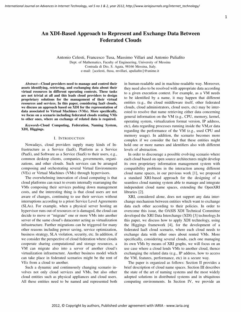
In this Section, we briefly summarize the main cloudname space issues which have already been analyzed in [5].Despite the internal cloud structure, we think cloud entitieshave many logical representations in various contexts. Inaddition, there are many abstract, structured entities (e.g., adistributed cloud-service built using other services, each onedeployed in a different VE). These entities are characterizedby a high-level of dynamism: allocations, changes anddeallocations of VEs may occur frequently. Moreover, theseentities may have one or more logical representations inone or more contexts. But which are the entities involvedin cloud computing? In order to describe such entities, weintroduce the generalized concept of Cloud Named Entity(CNE). A CNE is a generic entity indicated by a nameor an identifier which may refer both to real/abstract andsimple/structured entity. As depicted in Figure 1, examplesof CNE may be a cloud itself, a cloud federation, a vir-tualization infrastructure, a server running an hypervisor, aVE, a cloud service, or cloud users including companies,governments, universities, cloud technicians, and desktopclients.
Figure 1. Examples of generic CNEs.
In our abstraction, we assume that a CNE is associatedto one or more identifiers. As a CNE is subject to frequentchanges holding different representations in various CloudContexts (CCNTXs), the user-centric identity model [6]seems to be the most convenient approach. We define a
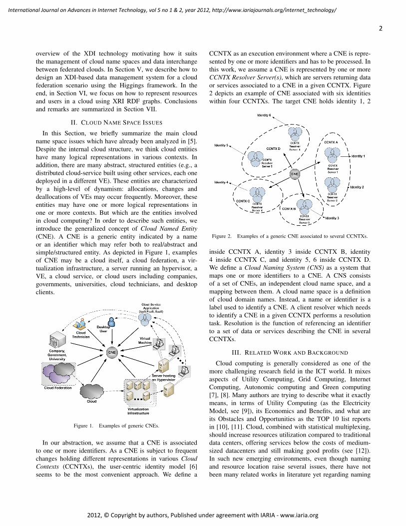
CCNTX as an execution environment where a CNE is repre-sented by one or more identifiers and has to be processed. Inthis work, we assume a CNE is represented by one or moreCCNTX Resolver Server(s), which are servers returning dataor services associated to a CNE in a given CCNTX. Figure2 depicts an example of CNE associated with six identitieswithin four CCNTXs. The target CNE holds identity 1, 2
Figure 2. Examples of a generic CNE associated to several CCNTXs.
inside CCNTX A, identity 3 inside CCNTX B, identity4 inside CCNTX C, and identity 5, 6 inside CCNTX D.We define a Cloud Naming System (CNS) as a system thatmaps one or more identifiers to a CNE. A CNS consistsof a set of CNEs, an independent cloud name space, and amapping between them. A cloud name space is a definitionof cloud domain names. Instead, a name or identifier is alabel used to identify a CNE. A client resolver which needsto identify a CNE in a given CCNTX performs a resolutiontask. Resolution is the function of referencing an identifierto a set of data or services describing the CNE in severalCCNTXs.
III. RELATED WORK AND BACKGROUND
Cloud computing is generally considered as one of themore challenging research field in the ICT world. It mixesaspects of Utility Computing, Grid Computing, InternetComputing, Autonomic computing and Green computing[7], [8]. Many authors are trying to describe what it exactlymeans, in terms of Utility Computing (as the ElectricityModel, see [9]), its Economics and Benefits, and what areits Obstacles and Opportunities as the TOP 10 list reportsin [10], [11]. Cloud, combined with statistical multiplexing,should increase resources utilization compared to traditionaldata centers, offering services below the costs of medium-sized datacenters and still making good profits (see [12]).In such new emerging environments, even though namingand resource location raise several issues, there have notbeen many related works in literature yet regarding naming
2
International Journal on Advances in Internet Technology, vol 5 no 1 & 2, year 2012, http://www.iariajournals.org/internet_technology/
2012, © Copyright by authors, Published under agreement with IARIA - www.iaria.org
systems managing cloud name spaces, and DNS is stillerroneously considered the “panacea for all ills”. In fact,DNS presents some problems: it is host centric, unsuitablefor complex data and services location, and it is not suited toheterogeneous environments. Possible improvements mightcome from the naming system works in high-dynamic,heterogeneous and ubiquitous environments. An alternativeto DNS is presented in [13]. The authors propose a UniformResource Name System (URNS), a decentralized solutionproviding a dynamic and fast resource location system forthe resolution of miscellaneous services. Nevertheless, thework lacks of an exhaustive resource description mechanism.With regard to naming system in ubiquitous computing, in[14] the authors propose a naming system framework forsmart space environments. The framework aims to integrateP2P independent cloud naming systems with the DNS,but appears unfitted to be exported in other environments.In addition it aims to localize and identify an entity thatmoves from a smart space to another using as descriptionmechanism the little exhaustive DNS resource records. Ahybrid naming system that combines DNS and DistributedHash Table (DHT) is presented in [15]. The authors adopt aset of gateways executing a dynamic DNS name delegationbetween DNS resolver and DHT node.
An interesting survey among different technologies forthe Resource Discovery in Grid Environments has beendone in [16]. The authors presented a valuable comparisonamong the P2P protocols ranging from Napster, Gnutella,CAN to Chord. It is interesting to notice the punctualevaluation (even taking into account the complexity of eachone) of these protocol and their applicability in Grids. Theymentioned that one of the main constrains in Grid is thescalability. Some of the protocols reported above are notreally fully decentralized. (i.e., Napster) whereas others donot guarantee the operating in heterogeneous Grid environ-ments. Other evaluations were conducted in [17] and [18].Their assessments are about the possibility to use in Gridconsolidated protocols for the Resource Discovery (RD)tasks. However many solutions adopted in Grid ([19]) alongwith the advanced DHT usage (see [20]), are not suitable inclouds at all. We can affirm that the level of heterogeneity inClouds is higher of any Grid infrastructure. For that reasonwe cannot consider solutions embraced in Grid, but wehave to look solutions widely used in distributed system asInternet (i.e., DNS approach). In our point of view conceptsof systems heterogeneity and federation mechanisms needto be taken into account. Whether we consider the recentconvergence of Web SSO systems in the Internet, in thelast years we assisted to a wide use of OpenID [21]. It isconsidered as one of the widely digital identity protocol usedfor making Federation among web services. Providers thatadopted such a technique range from AOL, BBC,Google,IBM, MySpace, Orange, PayPal, VeriSign, LiveJournal, toYahoo [22]. The new version of OpenID, 2.0 was released to
overcome some big issues [23]. The way for improving it, isto implement several clausals existing in the XRI StandardSpecification [24], [25].
We can assume the XRI standard as a step over of theDNS protocol. All enterprises may continue in using theirinternal systems for cataloging resources and services, asLDAP, Active Directory (AD), owned database, etc; allthese protocols are based on DNS. Our idea is to have analternative to DNS, a kind of advanced DNS protocol, that isXRI, compliant with URI/URL approach able to overcomeDNS limitations, also in terms of its representativeness. Wecan state that XRI might represent an useful abstractionof what already exists in the Internet. In particular weremind the XRI syntax and resolution infrastructure wasdesigned explicitly for Internet-scale digital identity, andwe are adopting it for enriching exchanged information inmuch more complex cloud scenarios maintaing its basicphilosophy indispensable for the Federated Digital Identitymanagement.
Regarding naming, name resolution, and service locationin federated cloud environments, in our previous work [26],we highlighted the involved issues both debating a cloudname space analysis and proposing a generic theoreticalcloud naming framework for the management of cloud namespaces. The cloud federation is a scenario where cloudsestablish a relationship in order to benefit new businessadvantages [27], for example renting single VM or wholecloud services to other clouds, for example when a cloudrun out its computational and storage capabilities or whena cloud needs a service which is not able to allocate.In [28], considering such a cloud naming framework andseveral use-cases of the European Reservoir Project [29], weperformed an analysis of the problems that such use-casesraise regarding the management of cloud name spaces, alsodebating how the aforementioned cloud naming frameworkcould be adopted to manage naming and service resolution.As possible representation of the cloud naming frameworkwe chose XRI [24] and the eXtensible Resource DescriptorSequence (XRDS) [25] technologies. The major open sourceimplementation of XRI is OpenXRI [2], which provides abasic Authority Resolution server along with java librariesfor the development of XRI-based applications. Anotherinteresting initiative is the Higgings Personal Data Service[4] framework developed by the Eclipse community. Hig-gings implements the XRI Data Interchange (XDI) [30],i.e., a generalized, extensible service for sharing, linking,and synchronizing structured data over the Internet usingXRI-addressable RDF graphs. As well as XRI, XDI is underdevelopment by the OASIS [31] Technical Committee.
IV. XDI AND CLOUD COMPUTING
In this Section, after a brief description the XDI tech-nology, we motivate how it can help the cloud name spacemanagement and data interchange between federated clouds.
3
International Journal on Advances in Internet Technology, vol 5 no 1 & 2, year 2012, http://www.iariajournals.org/internet_technology/
2012, © Copyright by authors, Published under agreement with IARIA - www.iaria.org

A. XDI Overview
XDI (XRI Data Interchange) is a generalized, extensibleservice for sharing, linking, and synchronizing structureddata over the Internet and other data networks using XRI-addressable RDF graphs. XDI is under development bythe OASIS XDI Technical Committee. The main featuresof XDI are: the ability to link and nest RDF graphs toprovide context; full addressability of all nodes in the graphat any level of context; representation of XDI operationsas graph statements so authorization can be built into thegraph (i.e., a feature called XDI link contracts); standardserialization formats including JSON and XML; and a sim-ple ontology language for defining shared semantics usingXDI dictionary services. The XDI protocol can be boundto multiple transport protocols. The XDI TC is definingbindings to HTTP and HTTPS, however it is also explor-ing bindings to XMPP and potentially directly to TCP/IP.XDI provides a standardized portable authorization formatcalled XDI link contracts. Link contracts are themselvesXDI documents (which may be contained in other XDIdocuments) that enable control over the authority, security,privacy, and rights of shared data to be expressed in astandard machine-readable format and understood by anyXDI endpoint. XDI enable to achieve a secure interchangeof data between different software entities by means ofsecure communication channels. These channels can besecured through different techniques, including the SecurityAssertion Markup Language (SAML), based on the IdentityProvider/Service Provider (IdP/SP) model.
RDF graphs are created using XRI, i.e., a standard syntaxfor identifying entities, regardless any particular concreterepresentation. The XRI system is similar to DNS, includinga set of hierarchical XRI authorities but more powerful.The protocol is built on URI (Uniform Resource Identifiers)and IRI (Internationalized Resource Identifiers) extendingtheir syntactic elements and providing parsing mechanisms.Particular types of URI are URN and URL. Since an URLis also an URI, the protocol provides a parsing mechanismfrom XRI to URL. Therefore XRI is also compatible withany URN domain. XRI supports persistent and reassignableidentifiers by means of i-numbers (Canonical ID) and i-names (Local ID). It also provides four types of synonyms(LocalID, EquivID, CanonicalID, and CanonicalEquivID) toprovide robust support for mapping XRIs, IRIs, or URIs toother XRIs, IRIs, or URIs that identify the same target entity.This is particularly useful for discovering and mappingto persistent identifiers as often required by trust infras-tructures. XRI enable organization to logically organizeentities building XRI RDF graphs. According to the XRIterminology, each entity in the graph is named authority.The protocol provides two additional options for identifyingan authority: Global Context Symbols (GCS) and cross-references. Common GCS are “=” for people, “@” for
organization, and “+” for generic concepts. For example thexri://@XYZ*marketing indicates the marketing branch of anorganization named XYZ, where the “*” marks a delegation.
B. Why Does XDI suit Cloud Computing?
XDI meets the requirements of cloud name space man-agement, data retrieval and data interchange especially infederated cloud environments. With XDI a cloud can keepdifferent RDF graphs representing IaaS, PaaS, and SaaS. Inaddition, such a technology can be used for both identifyand resolve VMs and whole *aaS by means of data retrievalmechanisms. For example, the cloud service provider mayneed to retrieve three types of information about a VM:general data (e.g., CPU, memory, kernel, operating system);real time performance data (e.g., amount of used CPU andmemory used); real time data regarding an internal runningprocess (e.g., the percentage of processed data). Moreover,considering IaaS federated clouds, each provider needs toexchange part of its data with other clouds. For example,let us consider two clouds: A and B. Cloud A, logicallyorganize its own VMs by means of an XRI graph. As CloudB has run out of resources, it require three VMs to cloudA. So that, cloud A instantiate the three VMs and update itsXRI graph. Then, in order to allow cloud B to access theVMs, cloud A, after an authentication of cloud B, discloseshow to access the VMs and related data. Authenticationcan be easily achieved using SAML Single Sign-On (SSO)mechanisms.
In addition, XDI might be used to logically representinstances of composed services. For example, let us considera service instance composed of several elementary serviceseach one running in a different VM. Thanks to XDI it ispossible to create in the graph of a cloud an entry repre-senting the service instance, linking the entries representingthe VMs on which the service instance is made up. Otherpossible applications of XDI can regard for example themanagement of physical assets, clients, and so on.
V. HOW TO ACHIEVE XDI IN FEDERATED CLOUD USINGHIGGINGS
Starting from the considerations of the previous Section,in the following we will point out a concrete scenario ofcloud federation, specifically aimed to the IaaS context. Inorder to address either the problem of sharing informationamong clouds and achieving their authentication process,we rely on the XDI features. More specifically, our sce-nario takes advantage of the employment of the Higgingsframework, that represents a Personal Data Service (PDS)including the implementation of XDI features.
In the first part of the Section we will introduce and de-scribe the Higgings Framework, whereas in the second partwe will present the reference scenario where our solutionaims to address the IaaS cloud federation problem.
4
International Journal on Advances in Internet Technology, vol 5 no 1 & 2, year 2012, http://www.iariajournals.org/internet_technology/
2012, © Copyright by authors, Published under agreement with IARIA - www.iaria.org

A. The Higgings Framework
Higgins is an open source project that aims to provide toindividuals more control over their personal identity, profileand social network data.
The project is organized into three main areas:1) Active Clients. An active client integrates with a
browser and runs on a computer or mobile device.• Higgins 1.X: the active client supports the OASIS
IMI protocol and performs the functions of anInformation Card selector.
• Higgins 2.0: the plan is to move beyond selectorfunctionality to add support for managing pass-words, Higgins relationship cards, as well otherprotocols such as OpenID. It also becomes aclient for the Personal Data Store (see below) andthereby provides a kind of dashboard for personalinformation and a place to manage “permission-ing” deciding who gets access to what slice of theuser’s data.
2) Personal Data Store (PDS) is a new work areaunder development for Higgins 2.0. A PDS storeslocal personal data, controls access to remotely hostedpersonal data, synchronizes personal data to otherdevices and computers, accessed directly or via a PDSclient. It allows the user to share selected aspects oftheir information with people and organizations thatthey trust.
3) Identity Services - Code for (i) an IMI and SAMLcompatible Identity Provider and (ii) enabling websitesto be IMI and OpenID compatible.
B. Reference Scenario
As we have already introduced, in this Section we con-sider the IaaS cloud federation scenario. In particular, wesuppose to have a wide distributed infrastructure, composedof different clouds, belonging to different administrativedomains. Each cloud is able to satisfy service requests (in thecase of IaaS we consider VMs as resources) coming from itsusers. When, for some reason (e.g. a temporary load peak)a given cloud is not able to satisfy users’ requests anymore,instead of rejecting them, it could ask the additional neededresources to external providers. These latter might be otherclouds able to join the federation.
Obviously, the achievement of this process may be dif-ficult due to several issues that have to be addressed: firstof all, when a cloud has expired its resources and ask themto external providers, these have to correctly identify theentity that have generated the request, and accept it onlyif it has been originated from a trusted source. This leadsto the need of managing the authentication process. Thesimplest solution consists in the possibility of creating a setof credentials for each cloud, on every other cloud aimingto attend the federation. Even though this solution is the
straightforward one, its applicability is limited to a scenariojust formed by a small number of entities. If we consider thehypotheses of a growing number of clouds, the creation ofcredentials for each one may be a different task to manage.
In order to simplify the authentication in such scenarios,the most common adoptable solution might be based on theSSO. Instead of creating lots of credentials for authenticatingeach cloud on the others, it could be employed a more flex-ible solution relying on trusted third-parties. This approachminimizes the number of expected credentials, since a givencloud just need to have an account on one (or more) of thesethird-party to be authenticated on all the entities (clouds) thatare trusted with them.
Once the authentication task has been solved, in order toallow resources sharing among the cloud federation entities,a way to organize clouds information is also needed. Acloud service provider, in fact, may need different kindsof information regarding VMs: associated resources, in-stantaneous workload and internal application state. In afederated environment, part of this information might beshared among the entities taking part to the infrastructure.As we have already pointed out previously, if each cloudstores information by means of an RDF XRI graph, theprocess of communicating requests for new resources, theirallocation on external providers and finally their exploitingwill be more flexible and simpler. Section VI will providemore details and examples on RDF XRI graphs generatedin our testbed.
For addressing either authentication and information shar-ing among clouds aiming to federate themselves, we proposethe employment of an XDI based framework whose imple-mentation, in our case, relies on Higgings. In the followingwe provide an overview of the operations involved in thecreation of a binding among two different clouds for sharingresources: we will assume that the involved entities arebased on Higgings for implementing their features. Oncethe authentication process is performed using the SSO, theinvolved clouds will the able to share the needed informationusing the XRI representation transmitting them over a securechannel created among them.
Assuming the internal cloud organization as depicted inFigure 3, we can consider a three layered stack where inthe top part lies the cloud manager layer (that manages allthe high-level operations such as authentication, resourcediscovery etc.).
As the Figure shows, Cloud Manager includes the Re-source Manager, which is able to manage resources allo-cation on external providers if needed through the Cross-cloud Federation Manager component. (for further detailssee [27]). When a cloud (we call it Cloud A) has expiredits own resources and needs to gain them from the outside,a Discovery process is started from the Resource Manager.The result of this task will be a list of external clouds ableto satisfy the request. From the retrieved set, it will be
5
International Journal on Advances in Internet Technology, vol 5 no 1 & 2, year 2012, http://www.iariajournals.org/internet_technology/
2012, © Copyright by authors, Published under agreement with IARIA - www.iaria.org

Figure 3. Three layered organization of a Cloud
necessary to select the cloud resource provider best fittingthe request: such a task will be accomplished during theMatch-Making process. The result of this last operation willconsist in the URL of the cloud able to satisfy the resourcesneed of Cloud A (in our case we assume Cloud B as thecloud selected from the Match-Making).
Figure 4 shows the steps involved in the authenticationand information sharing between two different clouds (CloudA and Cloud B): in step 1, the URL coming out from theMatch-Making process is used by the Authentication Agentof Cloud A for contacting the destination cloud from whichgaining external resources (Cloud B). An HTTP post isforwarded (step 2) with the username and session key (ifexists) to the Authentication Agent of Cloud B. The sessionkey is used by the AA of Cloud A as a token proving thata login has been correctly performed on a given IdP andidentifies a communication session in a unique way. Thismeans that the key will exist only if the AA already hasperformed the authentication with an IdP and a session hasbeen created.
During the step 3, the AA of Cloud A is redirected to theIdP trusted with Cloud B for verifying its identity. In step 4,the IdP receives from the AA of Cloud A information aboutthe username and the session key and verifies the existenceof a binding between that username and that session keyquerying a local Database. If an entry exists within theDatabase, a session for Cloud A has been already createdand IdP sends an answer with StatusCode 200, otherwisethe login process has to be started for proving the identityof the cloud.
In the last case, in step 5, the AA of Cloud A sendits username and password to the IdP that verifies themchecking within the LDAP server: if a user exists with thatcredentials, a new session key is saved within the localDatabase associated to the username and is sent back tothe AA of the Cloud A.
Now that the login phase has been accomplished and theAA of Cloud A holds a valid session key (also registeredwithin the Database), in step 6, it is redirected to the AA of
Cloud B where it is now authenticated and able to performoperations: using its username and its session key, Cloud Acan now perform the operations needed for creating VMsinstances within Cloud B. In the example reported in Figure4, the Add operation is performed for allocating 3 new VMs.
The AA of Cloud B receives the request and controlthe associated username and session key: such informationare then forwarded to the component that is responsible ofmanaging the XRI graph, which performs the addition ofthe needed nodes and associate them with the session keyassociated to the username from which the VMs request iscoming. From now on, only the entity that holds that key willbe able to access those graph node for retrieving informationon the new instantiated VMs. An example of possible XRIgraphs of cloud A and B is analyzed in the next Section.
Figure 4. Authentication process and resource information sharing amongCloud A and Cloud B
VI. XRI GRAPH REPRESENTATION OF VMS
In this Section, we show how can be possible to logicallyorganize and manage data associated to a cloud providerby means of XDI and XRI-addressable RDF graphs. Morespecifically, considering the scenario, we have alreadypointed out, we discuss how to represent both VMs hostedwithin the cloud data-center and VMs lent/borrowed to/fromother cloud providers. Moreover, for each XRI graphs, wewill show the corresponding XDI documents generated inour testbed. XDI allows to represent RDF XRI graph bymeans of three main elements:
• Subject, e.g., <xdi:s xri=”entry”> ... </xdi:s>. It canbe a real/abstract entity represented by means of anXRI entry. Examples can be, the cloud iteself, anadministrative domain, a cluster, a server, a VM, acloud-based service instance, an user, etc.
• Reference, e.g., <xdi:ref xri=”entry”> ... </xdi:ref>.It is a reference to a subject.
• Predicate, e.g., <xdi:p xri=”relation”> ... </xdi:p>. Itcan be relation between two or more subjects.
At the beginning, how depicted in Figure 5, cloud A hasan administrative domain including cluster1 and cluster2.Cluster 1 includes server1 which hosts VM1 and VM2,
6
International Journal on Advances in Internet Technology, vol 5 no 1 & 2, year 2012, http://www.iariajournals.org/internet_technology/
2012, © Copyright by authors, Published under agreement with IARIA - www.iaria.org

instead cluster 2 includes server2 which hosts VM3. CloudA has also two users: user1 and user 2. User1 holds VM1hosted in server1 of cluster1 and VM3 hosted in server 2 ofcluster 2. User 2 holds VM2 hosted in server1 of cluster1.
Figure 5. Cloud A graph before federation.
The corresponding XDI code is shown in the following.<?xml v e r s i o n = ” 1 . 0 ” e n c o d i n g =”UTF−8”?><x d i : x d i xmlns : x d i =” h t t p : / / x d i . o a s i s−open . o rg”>
<x d i : s x r i =”= u s e r 1”><x d i : p x r i =” $has$a”>
<x d i : r e f x r i =”+VM1”/><x d i : r e f x r i =”+VM3”/>
</ x d i : p></ x d i : s><x d i : s x r i =”= u s e r 2”>
<x d i : p x r i =” $has$a”><x d i : r e f x r i =”+VM2”/>
</ x d i : p></ x d i : s><x d i : s x r i =”+ e x t e r n ”/><x d i : s x r i =”+ admin”>
<x d i : p x r i =” $has”><x d i : r e f x r i =”+ c l u s t e r 1 ”/><x d i : r e f x r i =”+ c l u s t e r 2 ”/>
</ x d i : p></ x d i : s><x d i : s x r i =”+ admin+ c l u s t e r 1 ”>
<x d i : p x r i =” $has”><x d i : r e f x r i =”+ s e r v e r 1 ”/>
</ x d i : p></ x d i : s><x d i : s x r i =”+ admin+ c l u s t e r 2 ”>
<x d i : p x r i =” $has”><x d i : r e f x r i =”+ s e r v e r 2 ”/>
</ x d i : p></ x d i : s><x d i : s x r i =”+ admin+ c l u s t e r 1 + s e r v e r 1”>
<x d i : p x r i =” $has”><x d i : r e f x r i =”+VM1”/><x d i : r e f x r i =”+VM2”/>
</ x d i : p></ x d i : s><x d i : s x r i =”+ admin+ c l u s t e r 2 + s e r v e r 2”>
<x d i : p x r i =” $has”><x d i : r e f x r i =”+VM3”/>
</ x d i : p></ x d i : s><x d i : s x r i =”+VM2”>
<x d i : p x r i =”DATA”><x d i : da t a ><![CDATA[DATA]]></ x d i : da t a>
</ x d i : p></ x d i : s>
<x d i : s x r i =”+VM3”><x d i : p x r i =”DATA”>
<x d i : da t a ><![CDATA[DATA]]></ x d i : da t a></ x d i : p>
</ x d i : s><x d i : s x r i =”+VM1”>
<x d i : p x r i =”DATA”><x d i : da t a ><![CDATA[DATA]]></ x d i : da t a>
</ x d i : p></ x d i : s><x d i : s x r i =”+ admin+ c l u s t e r 1 + s e r v e r 1 +VM1”/><x d i : s x r i =”+ admin+ c l u s t e r 1 + s e r v e r 1 +VM2”/><x d i : s x r i =”+ admin+ c l u s t e r 2 + s e r v e r 2 +VM3”/>
</ x d i : xdi>
At the same time (see Figure 6), cloud B includes cluster1with server1 and server2. Server1 hosts VM1 and VM2,instead server2 hosts VM3. For simplicity, let us supposethat all VMs are reserved.
Figure 6. Cloud B graph before federation.
The corresponding XDI code is shown in the following.<?xml v e r s i o n = ” 1 . 0 ” e n c o d i n g =”UTF−8”?><x d i : x d i xmlns : x d i =” h t t p : / / x d i . o a s i s−open . o rg”>
<x d i : s x r i =”+ e x t e r n ”/><x d i : s x r i =”= admin”>
<x d i : p x r i =” $has”><x d i : r e f x r i =”+ c l u s t e r 1 ”/>
</ x d i : p></ x d i : s><x d i : s x r i =”= admin+ c l u s t e r 1 ”>
<x d i : p x r i =” $has”><x d i : r e f x r i =”+ s e r v e r 1 ”/><x d i : r e f x r i =”+ s e r v e r 2 ”/>
</ x d i : p></ x d i : s><x d i : s x r i =”= admin+ c l u s t e r 1 + s e r v e r 1”>
<x d i : p x r i =” $has”><x d i : r e f x r i =”+VM1”/><x d i : r e f x r i =”+VM2”/>
</ x d i : p></ x d i : s><x d i : s x r i =”= admin+ c l u s t e r 1 + s e r v e r 2”>
<x d i : p x r i =” $has”><x d i : r e f x r i =”+VM3”/>
</ x d i : p></ x d i : s><x d i : s x r i =”+VM2”>
<x d i : p x r i =”DATA”><x d i : da t a ><![CDATA[DATA]]></ x d i : da t a>
</ x d i : p></ x d i : s><x d i : s x r i =”+VM3”>
7
International Journal on Advances in Internet Technology, vol 5 no 1 & 2, year 2012, http://www.iariajournals.org/internet_technology/
2012, © Copyright by authors, Published under agreement with IARIA - www.iaria.org

<x d i : p x r i =”DATA”><x d i : da t a ><![CDATA[DATA]]></ x d i : da t a>
</ x d i : p></ x d i : s><x d i : s x r i =”+VM1”>
<x d i : p x r i =”DATA”><x d i : da t a ><![CDATA[DATA]]></ x d i : da t a>
</ x d i : p></ x d i : s><x d i : s x r i =”= admin+ c l u s t e r 1 + s e r v e r 1 +VM1”/><x d i : s x r i =”= admin+ c l u s t e r 1 + s e r v e r 1 +VM2”/><x d i : s x r i =”= admin+ c l u s t e r 1 + s e r v e r 2 +VM3”/>
</ x d i : xdi>
Then, let us suppose that user2 of cloudA requires threeadditional VMs. As cloud A realizes that it does not haveenough resources for instantiate further VMs, it establishes afederation with cloud B, as already described in the previousSection. After authentication, cloudA sends a request for theinstantiation of three VMs. So that, cloud B instantiates threeVMs in its own datacenter, i.e., VM4 in server1 and VM5and VM6 in server2. The corresponding updated graph isdepicted in Figure 7. Moreover, an user entry for cloud Ais created linking the three new instantiated VMs with areference to them.
Figure 7. Cloud B graph after federation.
The corresponding XDI code is shown in the following.<?xml v e r s i o n = ” 1 . 0 ” e n c o d i n g =”UTF−8”?><x d i : x d i xmlns : x d i =” h t t p : / / x d i . o a s i s−open . o rg”>
<x d i : s x r i =”+ e x t e r n ”/><x d i : s x r i =”= admin”>
<x d i : p x r i =” $has”><x d i : r e f x r i =”+ c l u s t e r 1 ”/>
</ x d i : p></ x d i : s><x d i : s x r i =”= admin+ c l u s t e r 1 ”>
<x d i : p x r i =” $has”><x d i : r e f x r i =”+ s e r v e r 1 ”/><x d i : r e f x r i =”+ s e r v e r 2 ”/>
</ x d i : p></ x d i : s><x d i : s x r i =”= admin+ c l u s t e r 1 + s e r v e r 1”>
<x d i : p x r i =” $has”><x d i : r e f x r i =”+VM1”/><x d i : r e f x r i =”+VM2”/><x d i : r e f x r i =”+VM4”/>
</ x d i : p></ x d i : s>
<x d i : s x r i =”= admin+ c l u s t e r 1 + s e r v e r 2”><x d i : p x r i =” $has”>
<x d i : r e f x r i =”+VM3”/><x d i : r e f x r i =”+VM6”/><x d i : r e f x r i =”+VM5”/>
</ x d i : p></ x d i : s><x d i : s x r i =”+VM2”>
<x d i : p x r i =”DATA”><x d i : da t a ><![CDATA[DATA]]></ x d i : da t a>
</ x d i : p></ x d i : s><x d i : s x r i =”+VM3”>
<x d i : p x r i =”DATA”><x d i : da t a ><![CDATA[DATA]]></ x d i : da t a>
</ x d i : p></ x d i : s><x d i : s x r i =”+VM1”>
<x d i : p x r i =”DATA”><x d i : da t a ><![CDATA[DATA]]></ x d i : da t a>
</ x d i : p></ x d i : s><x d i : s x r i =”= admin+ c l u s t e r 1 + s e r v e r 1 +VM1”/><x d i : s x r i =”= admin+ c l u s t e r 1 + s e r v e r 1 +VM2”/><x d i : s x r i =”= admin+ c l u s t e r 1 + s e r v e r 2 +VM3”/><x d i : s x r i =”+VM6”>
<x d i : p x r i =”DATA”><x d i : da t a ><![CDATA[DATA]]></ x d i : da t a>
</ x d i : p></ x d i : s>
<x d i : s x r i =”+ cloudA”><x d i : p x r i =” $has$a”>
<x d i : r e f x r i =”+VM6”/><x d i : r e f x r i =”+VM5”/><x d i : r e f x r i =”+VM4”/>
</ x d i : p></ x d i : s><x d i : s x r i =”+VM5”>
<x d i : p x r i =”DATA”><x d i : da t a ><![CDATA[DATA]]></ x d i : da t a>
</ x d i : p></ x d i : s><x d i : s x r i =”+VM4”>
<x d i : p x r i =”DATA”><x d i : da t a ><![CDATA[DATA]]></ x d i : da t a>
</ x d i : p></ x d i : s>
</ x d i : xdi>
Finally, cloud B sends the data related to the three instan-tiated VMs (e.g., how to access the VM, IP address, CPU,RAM, storage, operating system, etc) to cloud A whichupdate its XRI graph. For simplicity in the XDI document,we indicated such information with the string “DATA”. Asdepicted in Figure 8, cloud A, under the “extern” entry,creates an entry for cloud B, linking nodes representing thethree extern VMs. More specifically, +Ext-VM1, +Ext-VM2,+Ext-VM3 are aliases of the three VMs instantiated in cloudB.
The corresponding XDI code is shown in the following.
<?xml v e r s i o n = ” 1 . 0 ” e n c o d i n g =”UTF−8”?><x d i : x d i xmlns : x d i =” h t t p : / / x d i . o a s i s−open . o rg”>
<x d i : s x r i =”= u s e r 1”><x d i : p x r i =” $has$a”>
<x d i : r e f x r i =”+VM1”/><x d i : r e f x r i =”+VM3”/>
</ x d i : p></ x d i : s><x d i : s x r i =”= u s e r 2”>
<x d i : p x r i =” $has$a”><x d i : r e f x r i =”+VM2”/><x d i : r e f x r i =”+EXT+VM1”/><x d i : r e f x r i =”+EXT+VM3”/><x d i : r e f x r i =”+EXT+VM2”/>
8
International Journal on Advances in Internet Technology, vol 5 no 1 & 2, year 2012, http://www.iariajournals.org/internet_technology/
2012, © Copyright by authors, Published under agreement with IARIA - www.iaria.org
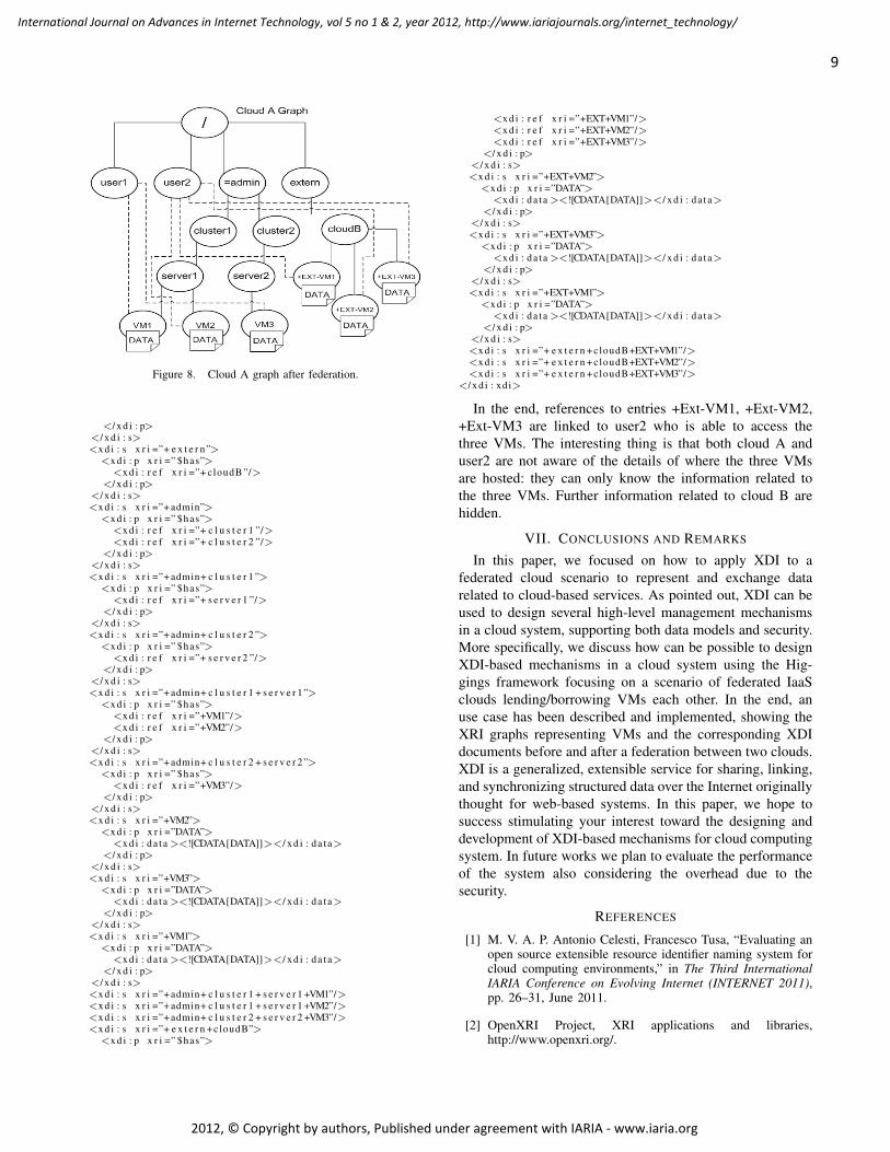
Figure 8. Cloud A graph after federation.
</ x d i : p></ x d i : s><x d i : s x r i =”+ e x t e r n”>
<x d i : p x r i =” $has”><x d i : r e f x r i =”+ cloudB ”/>
</ x d i : p></ x d i : s><x d i : s x r i =”+ admin”>
<x d i : p x r i =” $has”><x d i : r e f x r i =”+ c l u s t e r 1 ”/><x d i : r e f x r i =”+ c l u s t e r 2 ”/>
</ x d i : p></ x d i : s><x d i : s x r i =”+ admin+ c l u s t e r 1 ”>
<x d i : p x r i =” $has”><x d i : r e f x r i =”+ s e r v e r 1 ”/>
</ x d i : p></ x d i : s><x d i : s x r i =”+ admin+ c l u s t e r 2 ”>
<x d i : p x r i =” $has”><x d i : r e f x r i =”+ s e r v e r 2 ”/>
</ x d i : p></ x d i : s><x d i : s x r i =”+ admin+ c l u s t e r 1 + s e r v e r 1”>
<x d i : p x r i =” $has”><x d i : r e f x r i =”+VM1”/><x d i : r e f x r i =”+VM2”/>
</ x d i : p></ x d i : s><x d i : s x r i =”+ admin+ c l u s t e r 2 + s e r v e r 2”>
<x d i : p x r i =” $has”><x d i : r e f x r i =”+VM3”/>
</ x d i : p></ x d i : s><x d i : s x r i =”+VM2”>
<x d i : p x r i =”DATA”><x d i : da t a ><![CDATA[DATA]]></ x d i : da t a>
</ x d i : p></ x d i : s><x d i : s x r i =”+VM3”>
<x d i : p x r i =”DATA”><x d i : da t a ><![CDATA[DATA]]></ x d i : da t a>
</ x d i : p></ x d i : s><x d i : s x r i =”+VM1”>
<x d i : p x r i =”DATA”><x d i : da t a ><![CDATA[DATA]]></ x d i : da t a>
</ x d i : p></ x d i : s><x d i : s x r i =”+ admin+ c l u s t e r 1 + s e r v e r 1 +VM1”/><x d i : s x r i =”+ admin+ c l u s t e r 1 + s e r v e r 1 +VM2”/><x d i : s x r i =”+ admin+ c l u s t e r 2 + s e r v e r 2 +VM3”/><x d i : s x r i =”+ e x t e r n +cloudB”>
<x d i : p x r i =” $has”>
<x d i : r e f x r i =”+EXT+VM1”/><x d i : r e f x r i =”+EXT+VM2”/><x d i : r e f x r i =”+EXT+VM3”/>
</ x d i : p></ x d i : s><x d i : s x r i =”+EXT+VM2”>
<x d i : p x r i =”DATA”><x d i : da t a ><![CDATA[DATA]]></ x d i : da t a>
</ x d i : p></ x d i : s><x d i : s x r i =”+EXT+VM3”>
<x d i : p x r i =”DATA”><x d i : da t a ><![CDATA[DATA]]></ x d i : da t a>
</ x d i : p></ x d i : s><x d i : s x r i =”+EXT+VM1”>
<x d i : p x r i =”DATA”><x d i : da t a ><![CDATA[DATA]]></ x d i : da t a>
</ x d i : p></ x d i : s><x d i : s x r i =”+ e x t e r n +cloudB+EXT+VM1”/><x d i : s x r i =”+ e x t e r n +cloudB+EXT+VM2”/><x d i : s x r i =”+ e x t e r n +cloudB+EXT+VM3”/>
</ x d i : xdi>
In the end, references to entries +Ext-VM1, +Ext-VM2,+Ext-VM3 are linked to user2 who is able to access thethree VMs. The interesting thing is that both cloud A anduser2 are not aware of the details of where the three VMsare hosted: they can only know the information related tothe three VMs. Further information related to cloud B arehidden.
VII. CONCLUSIONS AND REMARKS
In this paper, we focused on how to apply XDI to afederated cloud scenario to represent and exchange datarelated to cloud-based services. As pointed out, XDI can beused to design several high-level management mechanismsin a cloud system, supporting both data models and security.More specifically, we discuss how can be possible to designXDI-based mechanisms in a cloud system using the Hig-gings framework focusing on a scenario of federated IaaSclouds lending/borrowing VMs each other. In the end, anuse case has been described and implemented, showing theXRI graphs representing VMs and the corresponding XDIdocuments before and after a federation between two clouds.XDI is a generalized, extensible service for sharing, linking,and synchronizing structured data over the Internet originallythought for web-based systems. In this paper, we hope tosuccess stimulating your interest toward the designing anddevelopment of XDI-based mechanisms for cloud computingsystem. In future works we plan to evaluate the performanceof the system also considering the overhead due to thesecurity.
REFERENCES
[1] M. V. A. P. Antonio Celesti, Francesco Tusa, “Evaluating anopen source extensible resource identifier naming system forcloud computing environments,” in The Third InternationalIARIA Conference on Evolving Internet (INTERNET 2011),pp. 26–31, June 2011.
[2] OpenXRI Project, XRI applications and libraries,http://www.openxri.org/.
9
International Journal on Advances in Internet Technology, vol 5 no 1 & 2, year 2012, http://www.iariajournals.org/internet_technology/
2012, © Copyright by authors, Published under agreement with IARIA - www.iaria.org
[3] D. Reed, G. Strongin, XDI (XRI Data Interchange), A WhitePaper for the OASIS XDI Technical Committee v2, OASIS,2004.
[4] “Higgings personal data service,http://www.eclipse.org/higgins/.”
[5] A. Celesti, M. Villari, and A. Puliafito, “Ecosystem of cloudnaming systems: An approach for the management and inte-gration of independent cloud name spaces,” (Los Alamitos,CA, USA), pp. 68–75, IEEE Computer Society, 2010.
[6] G.-J. Ahn, M. Ko, and M. Shehab, “Privacy-enhanced user-centric identity management,” in IEEE International Confer-ence on Communications, ICC ’09, pp. 14–18, June 2009.
[7] I. Foster, Y. Zhao, I. Raicu, and S. Lu, “Cloud computing andgrid computing 360-degree compared,” in Grid ComputingEnvironments Workshop, 2008. GCE ’08, pp. 1–10, 2008.
[8] R. L. Grossman, “The case for cloud computing,” in ITProfessional, vol. 11, pp. 23–27, March 2009.
[9] E. Brynjolfsson, P. Hofmann, and J. Jordan, “Cloud comput-ing and electricity: beyond the utility model,” Commun. ACM,vol. 53, pp. 32–34, May 2010.
[10] M. Armbrust, A. Fox, R. Griffith, A. D. Joseph, R. Katz,A. Konwinski, G. Lee, D. Patterson, A. Rabkin, I. Stoica, andM. Zaharia, “A view of cloud computing,” Commun. ACM,vol. 53, pp. 50–58, April 2010.
[11] M. Armbrust, A. Fox, R. Griffith, A. D. Joseph, R. H. Katz,A. Konwinski, G. Lee, D. A. Patterson, A. Rabkin, I. Stoica,and M. Zaharia, “Above the clouds: A berkeley view ofcloud computing,” Tech. Rep. UCB/EECS-2009-28, EECSDepartment, University of California, Berkeley, Feb 2009.
[12] R. Buyya, C. S. Yeo, S. Venugopal, J. Broberg, and I. Brandic,“Cloud computing and emerging it platforms: Vision, hype,and reality for delivering computing as the 5th utility,” FutureGeneration Computer Systems, vol. 25, no. 6, pp. 599 – 616,2009.
[13] D. Yang, Y. Qin, H. Zhang, H. Zhou, and B. Wang, “Urns: Anew name service for uniform network resource location,”in Wireless, Mobile and Multimedia Networks, 2006 IETInternational Conference, pp. 1–4, 2006.
[14] Y. Doi, S. Wakayama, M. Ishiyama, S. Ozaki, T. Ishihara,and Y. Uo, “Ecosystem of naming systems: discussions on aframework to induce smart space naming systems develop-ment,” in ARES, p. 7, April 2006.
[15] Y. Doi, “Dns meets dht: treating massive id resolution usingdns over dht,” in Applications and the Internet InternationalSymposium, pp. 9–15, January 2005.
[16] S. Chaisiri and P. Uthayopas, “Survey of resource discoveryin grid environments,” tech. rep., High Performance Com-puting and Networking Center, Department of ComputerEngineering, Faculty of Engineering, Kasetsart University,50 Phaholyothin Rd., Chatuchak, Bangkok 10900, Thailand,April 2008.
[17] A. Sharma and S. Bawa, “Comparative analysis of resourcediscovery approaches in grid computing.,” JCP, vol. 3, no. 5,pp. 60–64, 2008.
[18] A. Hameurlain, D. Cokuslu, and K. Erciyes, “Resourcediscovery in grid systems: a survey,” Int. J. MetadataSemant. Ontologies, vol. 5, pp. 251–263, July 2010.
[19] H. Sun, J. Huai, Y. Liu, and R. Buyya, “RCT: A distributedtree for supporting efficient range and multi-attribute queriesin grid computing,” Future Gener. Comput. Syst., vol. 24,no. 7, pp. 631–643, 2008.
[20] Y. Mei, X. Dong, W. Wu, S. Guan, and J. Li, “Sdrd: A novelapproach to resource discovery in grid environments,” inAdvanced Parallel Processing Technologies (M. Xu, Y. Zhan,J. Cao, and Y. Liu, eds.), vol. 4847 of Lecture Notes inComputer Science, pp. 301–312, Springer Berlin / Heidelberg,2007. 10.1007/978-3-540-76837-1 34.
[21] Wikipedia OpenID,http://en.wikipedia.org/wiki/OpenID, July 2011.
[22] OpenID World Wide Usage,http://www.ariadne.ac.uk/issue51/powell-recordon/, June2007.
[23] The Security Vulnerability of Reassignable Identifiers,http://dev.inames.net/wiki/XRI and OpenID, July 2011.
[24] Extensible Resource Identifier (XRI) Syntax V2.0, CommitteeSpecification, OASIS, 2005.
[25] Extensible Resource Identifier (XRI) Resolution V2.0, Com-mittee Draft 03, OASIS, 2008.
[26] A. Celesti, M. Villari, and A. Puliafito, “Ecosystem of cloudnaming systems: An approach for the management and in-tegration of independent cloud name spaces,” IEEE Interna-tional Symposium on Network Computing and Applications(IEEE NCA10), vol. 0, pp. 68–75, 2010.
[27] A. Celesti, F. Tusa, M. Villari, and A. Puliafito, “How toenhance cloud architectures to enable cross-federation,” in2010 IEEE 3rd International Conference on Cloud Comput-ing, pp. 337–345, IEEE, July 2010.
[28] A. Celesti, M. Villari, and A. Puliafito, “A Naming SystemApplied to a Reservoir Cloud,” in 2010 Sixth InternationalConference on Information Assurance and Security (IAS),pp. 247–252, IEEE, August 2010.
[29] Resources and Services Virtualization without Barriers(Reservoir) European Project,http://www.reservoir-fp7.eu/.
[30] “Xri data interchange, oasis, http://wiki.oasis-open.org/xdi/xdigraphmodel.”
[31] Organization for the Advancement of Structured InformationStandards (OASIS), http://www.oasis-open.org.
10
International Journal on Advances in Internet Technology, vol 5 no 1 & 2, year 2012, http://www.iariajournals.org/internet_technology/
2012, © Copyright by authors, Published under agreement with IARIA - www.iaria.org

Virtual Connections in P2P Overlays with DHT-Based Name to Address Resolution
Telesphore TiendrebeogoLaBRI
University of BordeauxTalence, France
Email: [email protected]
Daouda AhmatLaBRI
University of BordeauxTalence, France
Email: [email protected]
Damien MagoniLaBRI
University of BordeauxTalence, France
Email: [email protected]
Oumarou SieLTIC
University of OuagadougouOuagadougou, Burkina Faso
Email: [email protected]
Abstract—Current Internet applications are still mainlybound to their transport layer connections. This preventsmany features such as end-to-end security and mobility fromfunctioning smoothly in a dynamic network. In this paper, wepropose a novel architecture for decoupling communicationfrom their supporting devices. This enforces the completeseparation of devices, applications and entities such as users,services and data. Our architecture is based on a peer-to-peer overlay network where each peer has a permanent nameand a variable address which depends on its position in theoverlay. In order to dynamically map names to addresses, ourarchitecture provides its own distributed hash table system.After presenting the design of our architecture, we provide ascalability analysis and by performing simulations, we assessits efficiency. Simulation results show that our overlay using aname to address resolution based on a distributed hash table isscalable and has acceptable performances given the flexibilityit can provide to applications.
Keywords-overlay; virtual connection; distributed hash table;name resolution;
I. INTRODUCTION
Current Internet communications are still based on theparadigms set by the TCP/IP protocol stack 30 years agoand they are lacking several key features. Although manyefforts have been done during the last decade to providemobility, security and multicasting, those efforts have mainlybeen focused on the equipment itself (e.g., computers, smart-phones, routers, etc.) rather than on the logical part of thecommunication. In fact, although we already have a lot ofmobile equipment, it is still impossible to transfer a com-munication from one device to another without interruptingthe communication (and thus start it all over again). In thesame way, although we have the choice of many applicationsfor carrying one task, it is also still impossible to transfera communication from one application to another withoutinterrupting the communication. Layer 2 device mobility(e.g., WiFi, WiMAX, 3G and beyond) is nowadays wellsupported but users still have a very limited access to upperlayers mobility (e.g., MobileIP, TCP-Migrate).
In this paper, we propose and describe a new architecturefor using virtual connections setup over dynamic peer-to-peer (P2P) overlay networks built on top of the TCP/IPprotocol stack of the participating devices. We have named
this architecture CLOAK (Covering Layers Of AbstractKnowledge). This architecture supports names for entities(i.e., users, services, data) and devices, virtual addressesfor devices, and virtual sessions for managing all kindsof Internet communications. These new semantics broughtby our proposal open up many novel possibilities for suchcommunications. The virtual connections that are setup andmanaged by our solution, transparently handle the break-down and restore of transport layer connections (such asTCP or SCTP connections).
This paper is an extended version of our previouswork [1]. We have added here a detailed description ofthe Distributed Hash Table (DHT) mechanism deployed inCLOAK, an analysis of the complexity of the DHT interms of distances, states and messages, as well as addi-tional simulation results including comparative ones to otherexisting DHT systems. CLOAK was originally presentedin our paper [2] which contained an extensive amount ofbackground and related work as well as some preliminarysimulation results upon static networks concerning pathlength. Improving upon this foundation, our paper [1] pre-sented the protocols and modules of the architecture withgreater details and reported simulation results upon dynamicnetworks concerning routing success ratio, path length andstretch, as well as DHT requests performance indicators. Theaddressing and routing system based on hyperbolic geometrywhich is used by CLOAK was presented in our paper [3].Both the distributed addressing algorithm and the greedyrouting algorithm are detailed in this previous paper andwe have not included them here to avoid repetition. Theimplementation of the DHT scheme used by CLOAK overthis hyperbolic system is fully explained in Section IV.
The remainder of this paper is organized as follows.Section II presents the design and features of our architec-ture. Section III describes the main elements of its possibleimplementation. Section IV presents the binding algorithmused by our DHT. Section V compares the algorithmiccomplexity of our proposal to those of various existing DHTsystems. Section VI presents various results obtained bysimulations for evaluating the routing and binding efficiencyof our system. Section VII outlines the related previouswork done on transport layer mobility, name and address
11
International Journal on Advances in Internet Technology, vol 5 no 1 & 2, year 2012, http://www.iariajournals.org/internet_technology/
2012, © Copyright by authors, Published under agreement with IARIA - www.iaria.org
separation, as well as DHT schemes. We conclude the paperwith a summary of our contributions and present our futureresearch directions.
II. ARCHITECTURE
A. Design
In the context of our architecture, a communication isa set of interactions between several entities. It can beany form of simplex or duplex communication where in-formation is processed and exchanged between the entities(e.g., talk, view video, check bank account, send mail, etc.).An interaction is simply a given type of action carriedout between two or more entities by using an applicationprotocol (e.g., FTP, HTTP, etc.). An entity is typically ahuman user but it can also be an automated service suchas a server. A communication typically involves a minimumof two entities but it can involve many more in the case ofmulticast and broadcast communications. Finally, a deviceis a communication terminal equipment. On the device arerunning applications that are used by an entity to interactwith other entities. Given this context, the aim of ourarchitecture is to permit a communication to be carried outwithout any definitive unwanted interruption when some orall of its components (i.e., device, application or entity) areevolving (i.e., moving or changing) over space and time. Ourarchitecture ensures that a communication has a lifetime thatonly depends on the will of the currently implied entities.Changes in devices, applications and even entities (when itmakes sense) will not terminate the communication.
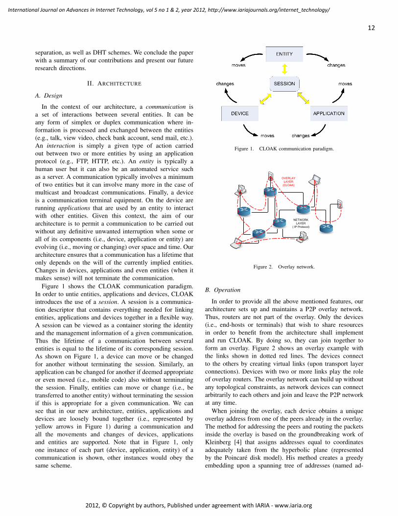
Figure 1 shows the CLOAK communication paradigm.In order to untie entities, applications and devices, CLOAKintroduces the use of a session. A session is a communica-tion descriptor that contains everything needed for linkingentities, applications and devices together in a flexible way.A session can be viewed as a container storing the identityand the management information of a given communication.Thus the lifetime of a communication between severalentities is equal to the lifetime of its corresponding session.As shown on Figure 1, a device can move or be changedfor another without terminating the session. Similarly, anapplication can be changed for another if deemed appropriateor even moved (i.e., mobile code) also without terminatingthe session. Finally, entities can move or change (i.e., betransferred to another entity) without terminating the sessionif this is appropriate for a given communication. We cansee that in our new architecture, entities, applications anddevices are loosely bound together (i.e., represented byyellow arrows in Figure 1) during a communication andall the movements and changes of devices, applicationsand entities are supported. Note that in Figure 1, onlyone instance of each part (device, application, entity) of acommunication is shown, other instances would obey thesame scheme.
Figure 1. CLOAK communication paradigm.
NETWORK LAYER
( IP Protocol)
OVERLAY LAYER
(CLOAK)
Figure 2. Overlay network.
B. Operation
In order to provide all the above mentioned features, ourarchitecture sets up and maintains a P2P overlay network.Thus, routers are not part of the overlay. Only the devices(i.e., end-hosts or terminals) that wish to share resourcesin order to benefit from the architecture shall implementand run CLOAK. By doing so, they can join together toform an overlay. Figure 2 shows an overlay example withthe links shown in dotted red lines. The devices connectto the others by creating virtual links (upon transport layerconnections). Devices with two or more links play the roleof overlay routers. The overlay network can build up withoutany topological constraints, as network devices can connectarbitrarily to each others and join and leave the P2P networkat any time.
When joining the overlay, each device obtains a uniqueoverlay address from one of the peers already in the overlay.The method for addressing the peers and routing the packetsinside the overlay is based on the groundbreaking work ofKleinberg [4] that assigns addresses equal to coordinatesadequately taken from the hyperbolic plane (representedby the Poincare disk model). His method creates a greedyembedding upon a spanning tree of addresses (named ad-
12
International Journal on Advances in Internet Technology, vol 5 no 1 & 2, year 2012, http://www.iariajournals.org/internet_technology/
2012, © Copyright by authors, Published under agreement with IARIA - www.iaria.org

dressing tree). This addressing tree is a regular tree of degreek. However in Kleinberg’s method, the construction of theembedding requires a full knowledge of the graph topologyand this topology must also be static. This is required as thedegree k of the addressing tree is set to the highest degreefound in the network. In our previous work [3], we haveenhanced his method in order to manage a dynamic topologywhich is able to grow and shrink over time. Because wesetup an overlay network, we are able to set the degree kof the addressing tree to an arbitrary value and as such, weare able to avoid the discovery of the highest degree node.This specificity renders our method scalable because unlikeKleinberg’s method [4], we do not have to make a two-pass algorithm over the whole network to find its highestdegree. The fixed degree that we choose determines howmany addresses each peer will be able to give. The degreeof the addressing tree is therefore set at the creation of theoverlay for all its lifetime. In the overlay however, a peer canconnect to any other peer at any time in order to obtain anaddress thus setting the degree does not prevent the overlayto grow. These hyperbolic addresses are appropriately givento the peers so that a greedy routing based on the hyperbolicdistance metric is guaranteed to work when the network isconnected. Thus, only the addresses of the neighbors of apeer are needed to forward a message to its destination.This is highly scalable as the peers do not need to build andmaintain routing tables.
In order to set up the DHT structure needed by ourarchitecture on top of the P2P overlay network, we onlyneed to add a mapping function between a keyspace and theaddressing space of the peers. When a peer wants to storean entry in the DHT, it first creates a fixed length key byhashing a key string with the SHA-1 algorithm. Then, thepeer maps the key to an angle by a linear transformation.The peer computes a virtual point on the unit circle byusing this angle. Next, the peer determines the coordinatesof the closest peer to the computed virtual point. The peerthen sends a store request to this closest peer. This requestis routed inside the overlay by using the greedy routingalgorithm presented above.
With the addressing, routing and mapping services pro-vided by our architecture, any user/entity of the P2P overlaynetwork can communicate with any other by setting upa virtual connection on top of the overlay. The steps forestablishing a communication between two entities of anoverlay are the following:
1) Bootstrap into the overlay by setting transport layerconnections to one or more devices (i.e., neighborpeers).
2) Obtain an overlay address from one of those neighborpeers.
3) Identify oneself in the overlay with unique device andentity identifiers.
4) Create a session.
Device BDevice ADevice C
Overlay connection(CLOAK)
Entity E -Entity F
Transport connection (e.g. TCP)
Device A – Device B
Link connection (e.g. Ethernet)
Router W – Router X
Router W Router X Router Y Router Z
Entity E
Entity F
Figure 3. Virtual connections.
Device BOV@ 2Device A
OV@ 1
Device COV@ 3
Device COV@ 4
Packet 1Dev A -> Dev C
Dest OV@ 3
Packet 2Dev A -> Dev C
Dest OV@ 3
Packet 3Dev A -> Dev C
Dest OV@ 4Device C moves to OV@ 4
Packet 4Dev A -> Dev C
Dest OV@ 4
Figure 4. Steering packets inside the overlay network.
5) Contact another entity to communicate with inside thissession.
6) Set an overlay layer virtual connection to this entityas shown in Figure 3.
7) Send the data stream through this connection.If an overlay address becomes invalid, two mechanisms
can be used to overcome routing failures. The first oneconsists, for intermediate nodes, in using the destinationname inside the packet header to query the DHT for itsnew address. If the DHT has a more recent (and thus valid)entry, the intermediate node will then be able to updatethe header with the new address and forward the packetaccordingly. The second one consists, for the destinationnode, in replacing its old address with its new one in theheader of its reply packets. Upon reception, the source nodewill then be able to update the destination address to thenewly received one. These mechanisms are illustrated inFigure 4. We call steering, the mechanism of querying theDHT on the fly by intermediate nodes. This mechanism alsoprovides multicast capability when it is performed in eachintermediate node. Indeed, a destination group name can besolved as several user names that again can be solved asoverlay addresses.
To be able to implement our architecture, we need tointroduce several new types of identifiers. More specificallywe need to define the following new namespaces:
13
International Journal on Advances in Internet Technology, vol 5 no 1 & 2, year 2012, http://www.iariajournals.org/internet_technology/
2012, © Copyright by authors, Published under agreement with IARIA - www.iaria.org

• Session namespace: any session is attributed a uniqueidentifier that defines the session during its lifetime inthe overlay.
• Device namespace: any device is attributed a uniqueidentifier that permanently represents the device. Thelifespan of this identifier is equal to the lifespan of itscorresponding device.
• Entity namespace: any entity is attributed a uniqueidentifier that represents the entity in a given context.It can be the name of a real person (John Smith) but itcould also be the identifier of a professional function(Sales Manager) or the name of an organization (Miche-lin Company) or a specific service (Areva Accountingservice). The lifespan of this identifier is equal to thelifespan of its corresponding entity.
• Application namespace: any application used during apart or all of a session is attributed a unique identifierfor receiving data from the other applications of thissession. The lifespan of this identifier is equal to thelifespan of the use of the application. If the entityswitches to another application, this identifier is up-dated.
The identifiers will be stored in a DHT built on the P2Poverlay network. Each peer will store a fraction of all therecords in its naming module. There will be records for thedevices (containing pairs like: device ID - overlay address),for the entities (containing pairs like: entity ID - device ID),for the applications (containing pairs like: application ID- session ID) and finally for the sessions (containing pairslike: session ID - session data information). An applicationusing CLOAK will not directly open a connection with anIP address and a port number as with the usual socketsAPI but it will use the destination’s entity ID as well as astream ID. Figure 5 shows a typical scenario relying on thisnaming system for solving an entity’s location. The yellowoval represents the CLOAK DHT. An entity B registers itselfin the DHT by providing the device identifier it is on and itsoverlay address. Any entity A can now retrieve the locationof B by querying the DHT. It can then connect to B viathe overlay. When B switches to another device during thesame session, A can reconnect to B by using its new overlayaddress.
As defined earlier, a session is a communication’s contextcontainer storing everything necessary to bind together en-tities, applications and devices that are involved in a givencommunication. Any device, application or entity can bechanged or moved without terminating the session. In orderto make this possible, the session will be stored in the DHTbuilt by the peers of the overlay network. The DHT willensure reliability by redundantly storing the sessions onseveral peers. This session management system ensures thesurvival of the session until all the entities involved decideto stop it. Figure 6 shows a typical scenario relying on this
Figure 5. Identification and localization.
Figure 6. Session management.
session management system. The yellow oval represents theCLOAK DHT. Let us assume that an entity A wants to starta video conference communication with an entity B. It firstcreates a session called X describing the desired interaction(e.g., video conference) as well as the destination entity thatit wants to communicate with (here the entity B). Then Asends an invite message to B that replies by joining thesession X. Later on the entity B invites another entity C toparticipate in the video conference. C accepts and joins thesession X. Three entities are now involved in the sessionX. Later on, the entity A leaves the session X withoutpreventing the others to continue. This thus does not endthe session X. Later on the entity C leaves the session X.The entity B being the last one involved decides to destroythe session and thus to end the communication.
C. Usage
Our architecture has a wide range of usages. It providesmechanisms for mobile and switchable applications, foradaptive transport protocol switching and for defining andusing new namespaces. It can build scalable and reliabledynamic Virtual Private Networks, define fully isolatedFriend-to-Friend networks, or be used as a convergencelayer for IPv4, NATs and IPv6. The Table I shows thebenefits of cloaked applications. Applications are groupedby families. Messaging applications contain e-mail, talkand chat programs. Conferencing applications regroup real-
14
International Journal on Advances in Internet Technology, vol 5 no 1 & 2, year 2012, http://www.iariajournals.org/internet_technology/
2012, © Copyright by authors, Published under agreement with IARIA - www.iaria.org

Table IFEATURES FOR cloaked APPLICATIONS.
Applications Messaging Conferencing Sharing StreamingReachability XMobility X XE2E privacy X XE2E auth. X XPseudonymity X XRedirection X XMulticasting X X X
time audio and video communications based on signalingprotocols such as SIP [5] and H.323 [6]. Sharing applicationsencompass file-sharing, blogging and social networking ap-plications. Finally, streaming applications contain audio andvideo broadcasting services such as Internet radios, IPTV,and VoD. Most of the features are usually self-explainingbut we give a few examples to highlight possible scenar-ios. Reachability is the ability to be reached on whateverdevice the user is currently using. When someone sendsa message to an entity, the CLOAK DHT can be useddynamically to determine on which device is the entityand the message is routed to the proper device. Mobilityis the ability of CLOAK to hide the handovers of thelower layers to the applications. If an entity is moving orswitching devices, real-time applications will be maintainedwithout interruption at the application level. CLOAK cansecure connections by using entity IDs rather than deviceIDs (or IP addresses such as in IPsec), thus establishingEnd-to-End (E2E) encryption and authentication. The publickeys of the peers can be stored in the DHT, howeverthe certification of these keys must be done by a trustedthird party. Because CLOAK packets usually transit throughseveral terminals before reaching destination, the IP addressof the source is often unknown to the destination thusproviding partial pseudonymity. Redirection is the abilityto forward a message or a stream to another entity. Finally,multicasting support is provided by CLOAK as group namescan be easily set up in the DHT. This feature is useful forsaving bandwidth during group communications.
III. IMPLEMENTATION
Figure 7 shows the OSI layers where the CLOAK ar-chitecture fits in. CLOAK uses the session layer and thepresentation layer between the transport and applicationlayers. These layers do not exist in the Internet stack modelbut they do already exist in the OSI model. In these twolayers we add two new protocols. We add a CLOAK sessionprotocol (CSP) at the session layer and a CLOAK interactionprotocol (CIP) at the presentation layer. We also define newidentifiers to be used by these new protocols. These newidentifiers enable data streams to be bound to entities insteadof network identifiers (i.e., IP address, protocol n◦, port n◦).As shown in Figure 1, identifiers for devices, applicationsand entities are interwoven together inside a session, but
Figure 7. CLOAK architecture in the OSI model.
for the purpose of implementation, we have to order them.We chose to manage a session and its involved devices atthe session layer. We also chose to manage the interactionsbetween entities at the presentation layer. As previously said,an interaction is a type of action carried out between two ormore entities. It is equal to the use of an existing applicationlayer protocol (e.g., FTP, SMTP, HTTP, etc.). Indeed, ourarchitecture will use the existing application layer protocolsas well as the existing transport layer protocols. Thus a filetransfer (FTP [7]) client application will still use the FTPprotocol to speak to a FTP server. Only the portion of codefor establishing a session and thus a connection to the serverwill have to be rewritten for using the CLOAK API insteadof the socket API [8]. The code implementing the applicationlayer protocol will not have to be changed. Please note thatthe CLOAK API and the mapping of application connectionsto transport sockets inside the middleware are not definedyet. They will be presented in a future work.
We have shown in Figure 7 how the CLOAK architecturefits in the network protocol stack. We will show how thisdesign translates into the format of the packet headers.Figure 8 shows a CLOAK packet exchanged between a Webclient and a Web server. The application header involving theHTTP protocol is now located after the CLOAK headers.We have added two additional headers. The CSP headeris located directly above the TCP protocol managing theconnection in the operating system of the device. It containsthe overlay addresses for routing inside the overlay andenabling device mobility, the device identifiers for switchingdevices and enabling entity mobility and the entity identifiersfor switching entities. The CIP header is located betweenthe CSP and the application level header. It is used foridentifying streams and applications. The stream identifiersare used as virtual port numbering on top of the entity. Theapplication identifiers are used for selecting or switching
15
International Journal on Advances in Internet Technology, vol 5 no 1 & 2, year 2012, http://www.iariajournals.org/internet_technology/
2012, © Copyright by authors, Published under agreement with IARIA - www.iaria.org

Figure 8. CLOAK protocol encapsulation.
applications when it makes sense in a communication.The definition and implementation of the CLOAK ad-
ditional protocols (CSP and CIP) and their correspondingheaders will help our architecture to solve some NATissues because applications using CLOAK will not use IPaddresses and ports numbers for setting up or managingconnections. They will use unique permanent entity iden-tifiers, thus restoring the end-to-end principle of the Internetcommunications. The CLOAK architecture will also solvesome firewall issues because any type and any number oftransport layer connections can be used to connect to aCLOAK overlay. A transport layer connection can act as amultiplex tunnel for the applications using CLOAK. Thuson a given device, the applications can even use only asingle port number and a single transport protocol if thisis required by the firewall of the device. Indeed, a CLOAKpacket has a session ID field and two stream ID fields thatenable numerous applications to be multiplexed on a singletransport connection if necessary. CLOAK also solves somesecurity issues because security will be implemented byusing entity identifiers instead of device identifiers or IPaddresses. The security will then be independent from thedevices and applications involved. Figure 9 shows the mod-ules composing the CLOAK middleware. The functionalitiesprovided by each module are:
• Bootstrap: primitives for creating a new or joining anexisting CLOAK overlay.
• Link: primitives for managing overlay links (i.e., trans-port layer connections) with the neighbor peers.
• Address: primitives for obtaining an overlay addressfrom an addressing tree parent and for distributingoverlay addresses to the addressing tree children.
• Route: primitives for routing the overlay packets withthe greedy algorithm using the hyperbolic distancemetric.
• Steer: primitives for rerouting overlay packets by usingtheir device or entity identifiers to update their overlaydestination address.
• Connect: primitives for establishing and managingoverlay virtual connections (i.e., CLOAK layer connec-tions) to other entities.
• Bind: primitives for querying the DHT of the overlay.• Name: primitives for managing the identifiers used by
the peer.
Transport API
CLOAK API
Figure 9. Modules of the middleware.
• Interact: primitives for managing the bindings betweenthe data streams and the applications.
IV. DHT-BASED NAME TO ADDRESS STORAGE
In this section we explain how our overlay system storesand retrieves the (name, address) pairs. Our solution is astructured DHT system that uses the distributed addressingand the greedy routing algorithms presented in our previouswork [3].
On startup, each new member of the overlay chooses aname that identifies the device it runs on. This name willbe kept by the device during all the lifetime of the overlay.When a new node obtains an address, it stores its name andits address in the DHT, with the name being used as the keyand the address as the value. If the same name is alreadystored in the DHT, an error message is sent back to the nodein order to ask the node to select another name. Thus theDHT structure itself ensures that names are unique.
A (key, value) pair is called a binding. Figure 10 showshow and where a given binding is stored in the overlay.A binder is any peer that stores these pairs. The depth ofa peer in the addressing tree is defined as the number ofparent peers to go through for reaching the root of the tree(including the root itself). When the overlay is created, amaximum depth for the potential binders is chosen. Thisvalue is defined as the binding tree depth. All the peers thathave a depth less or equal to the binding tree depth in theaddressing tree may hold bindings and thus be binders.
When a new peer joins the overlay by connecting to otherpeers, it obtains an address from one of these peers and itstores its own binding in the system. When a peer wants tostore an entry in the DHT, it first creates a key by hashing thename string with the SHA-1 algorithm. It then divides theresulting 160-bit key into r equally sized 160/r-bit subkeys(for redundancy storage). This r factor is chosen arbitrarily
16
International Journal on Advances in Internet Technology, vol 5 no 1 & 2, year 2012, http://www.iariajournals.org/internet_technology/
2012, © Copyright by authors, Published under agreement with IARIA - www.iaria.org
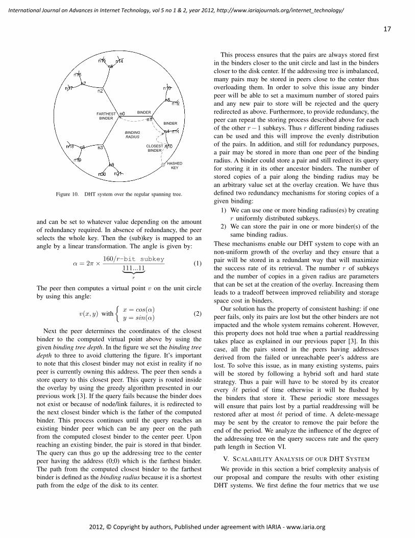
HASHED KEY
CLOSEST BINDER
BINDING RADIUS
FARTHEST BINDER
BINDER
BINDER
Figure 10. DHT system over the regular spanning tree.
and can be set to whatever value depending on the amountof redundancy required. In absence of redundancy, the peerselects the whole key. Then the (sub)key is mapped to anangle by a linear transformation. The angle is given by:
α = 2π × 160/r-bit subkey
111...11︸ ︷︷ ︸r
(1)
The peer then computes a virtual point v on the unit circleby using this angle:
v(x, y) with{x = cos(α)y = sin(α)
(2)
Next the peer determines the coordinates of the closestbinder to the computed virtual point above by using thegiven binding tree depth. In the figure we set the binding treedepth to three to avoid cluttering the figure. It’s importantto note that this closest binder may not exist in reality if nopeer is currently owning this address. The peer then sends astore query to this closest peer. This query is routed insidethe overlay by using the greedy algorithm presented in ourprevious work [3]. If the query fails because the binder doesnot exist or because of node/link failures, it is redirected tothe next closest binder which is the father of the computedbinder. This process continues until the query reaches anexisting binder peer which can be any peer on the pathfrom the computed closest binder to the center peer. Uponreaching an existing binder, the pair is stored in that binder.The query can thus go up the addressing tree to the centerpeer having the address (0;0) which is the farthest binder.The path from the computed closest binder to the farthestbinder is defined as the binding radius because it is a shortestpath from the edge of the disk to its center.
This process ensures that the pairs are always stored firstin the binders closer to the unit circle and last in the binderscloser to the disk center. If the addressing tree is imbalanced,many pairs may be stored in peers close to the center thusoverloading them. In order to solve this issue any binderpeer will be able to set a maximum number of stored pairsand any new pair to store will be rejected and the queryredirected as above. Furthermore, to provide redundancy, thepeer can repeat the storing process described above for eachof the other r−1 subkeys. Thus r different binding radiusescan be used and this will improve the evenly distributionof the pairs. In addition, and still for redundancy purposes,a pair may be stored in more than one peer of the bindingradius. A binder could store a pair and still redirect its queryfor storing it in its other ancestor binders. The number ofstored copies of a pair along the binding radius may bean arbitrary value set at the overlay creation. We have thusdefined two redundancy mechanisms for storing copies of agiven binding:
1) We can use one or more binding radius(es) by creatingr uniformly distributed subkeys.
2) We can store the pair in one or more binder(s) of thesame binding radius.
These mechanisms enable our DHT system to cope with annon-uniform growth of the overlay and they ensure that apair will be stored in a redundant way that will maximizethe success rate of its retrieval. The number r of subkeysand the number of copies in a given radius are parametersthat can be set at the creation of the overlay. Increasing themleads to a tradeoff between improved reliability and storagespace cost in binders.
Our solution has the property of consistent hashing: if onepeer fails, only its pairs are lost but the other binders are notimpacted and the whole system remains coherent. However,this property does not hold true when a partial readdressingtakes place as explained in our previous paper [3]. In thiscase, all the pairs stored in the peers having addressesderived from the failed or unreachable peer’s address arelost. To solve this issue, as in many existing systems, pairswill be stored by following a hybrid soft and hard statestrategy. Thus a pair will have to be stored by its creatorevery δt period of time otherwise it will be flushed bythe binders that store it. These periodic store messageswill ensure that pairs lost by a partial readdressing will berestored after at most δt period of time. A delete-messagemay be sent by the creator to remove the pair before theend of the period. We analyze the influence of the degree ofthe addressing tree on the query success rate and the querypath length in Section VI.
V. SCALABILITY ANALYSIS OF OUR DHT SYSTEM
We provide in this section a brief complexity analysis ofour proposal and compare the results with other existingDHT systems. We first define the four metrics that we use
17
International Journal on Advances in Internet Technology, vol 5 no 1 & 2, year 2012, http://www.iariajournals.org/internet_technology/
2012, © Copyright by authors, Published under agreement with IARIA - www.iaria.org

in our analysis. These metrics were defined and used in thesurvey of Lua et al. [9].
1) Hops: this metric counts the average number of peersto go through to reach the destination. It is also named:path length, routing distance or dilation.
2) Paths: this metric counts the average number of pathsthat are crossing any given peer. It is also namedcongestion.
3) States: this metric counts the number of states thatmust be stored in a peer for the routing to work, it istypically equal to the number of entries found in therouting table of the peer. It is also named routing ormemory states.
4) Churn messages: this metric counts the average num-ber of messages that are exchanged when a peer joinsor leaves the overlay. It is also named join/leave peersor linkage.
In our system, the peers in the overlay connect to eachothers as they wish, thus no strict topology is enforced. Anypeer can have as many links as it can with other peers andone link is of course a minimum to connect to the overlay.The only requirement is that the embedded addressing treewhich is a spanning tree of the overlay shall remain validfor the greedy routing to work.
Because any overlay will be at least (when no redundantlinks exist) composed of its addressing tree, the distancesbetween any two nodes are expected to be of the orderof O(log(n)) hops. If the peers have a large number ofredundant links (i.e., links not belonging to the addressingtree), the distances will be much shorter. If the overlaytopology takes the form of a scale free network [10], thedistances will be the order of O(log(log(n))) as shownin [11]. Whatever the topology, the number of paths crossingany one peer (its congestion level) will have an expectedprobability of at most O(log(n)/n).
When a peer joins the overlay, only its neighbors (i.e.,those having setup a link with the new peer) need toupdate their state information which bears a message costcomplexity independent of n. Similarly, when a peer leavesthe overlay, only its neighbors need to update their stateinformation also giving a message complexity cost being ofthe order of O(1). However, if the addressing tree is brokenand cannot be restored in a reasonable amount of time asexplained in our previous paper [3], a partial readdressingcan occur for peers having addresses derived from the failedor unreachable peer’s address. In this latter case, which isexpected to be very uncommon, the message cost complexityis expected to be of the order of O(n).
Readdressing is needed to provide to the peers the abilityof connecting to whatever peers they want. If we force somepeers to connect to some specific peers for restoring theaddressing tree (as done by Chord, where a peer’s IP addressdetermines to which peers it must connect) then the messagecost complexity is expected to be of the order of O(1) for
Table IIEXPECTED PERFORMANCE MEASURES OF VARIOUS DHT SYSTEMS.
Lookup Hops Paths States Churnmessages
CAN O(n(1/d)) O(n(1/d)/n) O(1) O(1)Chord O(log(n)) O(log(n)/n) O(log(n)) O(log2(n))CLOAK O(log(n)) O(log(n)/n) O(1) O(1)/O(n)Kademlia O(log(n)) O(log(n)/n) O(log(n)) O(log(n))Pastry O(log(n)) O(log(n)/n) O(log(n)) O(log(n))
a leaving peer. Thus readdressing must be seen as a costlyfeature that can be opted out if performance is desired overflexibility.
Because we use greedy routing, we do not construct andmaintain routing tables and the number of states to maintainin any one peer is only equal to the number of its neighborpeers which does not grow with n thus giving a constantcomplexity cost being of the order of O(1).
Table II compares the complexity costs of the four abovedefined metrics of various DHT systems including oursolution. For CAN, d is an integer equal to or greater than2 and thus 0 < 1/d < 1. The results presented in this tablehave been gathered by using the data published in [9] aswell as from our previous analysis. Note that log functionswith different constant bases are considered equivalent.
VI. SIMULATIONS
In this section, we present the preliminary results of thesimulations that we have carried out to establish a proof-of-concept of our dynamic P2P overlay architecture. Wehave used our packet-driven discrete event network simulatorcalled nem [12] for obtaining all the results shown in thispaper.
A. Parameters
In order to evaluate our overlay system on a realistic topol-ogy, we have used a 4k-node IP level Internet map createdfrom real data measurements with the nec software [13]. Inall simulations, the first peer creating the overlay is always arandomly picked node of the map. We have considered thatonly some nodes of a map at any given time are acting asoverlay peers. The simulator’s engine manages a simulationtime and each overlay peer starts at a given time for agiven duration on a random node of the map. The peer thatcreates the overlay remains active for all the duration ofa simulation. The packets are delivered between the nodesby taking the transmission time of the links into account.Peers bootstrap by contacting the node that holds the peerthat created the overlay, search for other peers to which theycan connect, obtain an address from one of the peers theyare connected to and send data or requests messages. Thisprocess models the birth, life and death of the overlay.
In any dynamic simulation, there is a warm up phase at thebeginning and a cool down phase at the end that must bothbe considered as transitory regimes. Indeed, at the beginning
18
International Journal on Advances in Internet Technology, vol 5 no 1 & 2, year 2012, http://www.iariajournals.org/internet_technology/
2012, © Copyright by authors, Published under agreement with IARIA - www.iaria.org
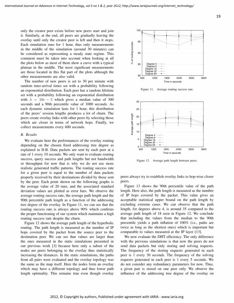
only the creator peer exists before new peers start and joinit. Similarly, at the end, all peers are gradually leaving theoverlay until only the creator peer is left and then it stops.Each simulation runs for 1 hour, thus only measurementsin the middle of the simulation (around 30 minutes) canbe considered as representing a steady state regime. Thiscomment must be taken into account when looking at allthe plots below as most of them show a curve with a typicalplateau in the middle. The most significant measurementsare those located in this flat part of the plots although theother measurements are also valid.
The number of new peers is set to 30 per minute withrandom inter-arrival times set with a probability followingan exponential distribution. Each peer has a random lifetimeset with a probability following an exponential distributionwith λ = 10e − 5 which gives a median value of 300seconds and a 90th percentile value of 1000 seconds. Aseach dynamic simulation lasts for 1 hour, this distributionof the peers’ session lengths produces a lot of churn. Thepeers create overlay links with other peers by selecting thosewhich are closer in terms of network hops. Finally, wecollect measurements every 600 seconds.
B. Results
We evaluate here the performances of the overlay routingdepending on the chosen fixed addressing tree degree asexplained in II-B. Data packets are sent by each peer at arate of 1 every 10 seconds. We only want to evaluate routingsuccess, query success and path lengths but not bandwidthor throughput for now that is why we do not use morerealistic generated traffic patterns. The routing success ratefor a given peer is equal to the number of data packetsproperly received by their destinations divided by those sentby the peer. Each point shown on the following graphs isthe average value of 20 runs, and the associated standarddeviation values are plotted as error bars. We observe theaverage routing success rate, the average path length and the90th percentile path length as a function of the addressingtree degree of the overlay. In Figure 11, we can see that therouting success rate is always above 90% which confirmsthe proper functioning of our system which maintains a highrouting success rate despite the churn.
Figure 12 shows the average path length of the hyperbolicrouting. The path length is measured as the number of IPhops covered by the packet from the source peer to thedestination peer. We can see that values are larger thanthe ones measured in the static simulations presented inour previous work [3] because here only a subset of thenodes are peers belonging to the overlay thus statisticallyincreasing the distances. In the static simulations, the pathsfrom all pairs were evaluated and the overlay topology wasthe same as the map itself. Here the nodes form an overlaywhich may have a different topology and thus lower pathlength optimality. This remains true even though overlay
80
85
90
95
100
600 1200 1800 2400 3000 3600
% o
f rou
ting
succ
ess
Time in seconds
Degree 4Degree 8
Degree 16Degree 32Degree 64
Figure 11. Average routing success rate.
0
5
10
15
20
25
30
600 1200 1800 2400 3000 3600
Ave
rage
pat
h le
ngth
Time in seconds
Degree 4Degree 8
Degree 16Degree 32Degree 64
Figure 12. Average path length between peers.
peers always try to establish overlay links to hop-wise closerpeers.
Figure 13 shows the 90th percentile value of the pathlength. Here also, the path length is measured as the numberof IP hops covered by the packet. This value gives anacceptable statistical upper bound on the path length byexcluding extreme cases. We can observe that the pathlength, for degrees above 4, is around 35 compared to theaverage path length of 18 seen in Figure 12. We concludethat including the values from the median to the 90thpercentile yields a path inflation of 100% (i.e., paths aretwice as long as the shortest ones) which is important butcomparable to values measured at the IP layer [13].
We now evaluate the DHT efficiency. The only differencewith the previous simulations is that now the peers do notsend data packets but only storing and solving requests.The frequency of the storing requests generated in eachpeer is 1 every 30 seconds. The frequency of the solvingrequests generated in each peer is 1 every 5 seconds. Wedo not consider any redundancy parameters for now. Thus,a given pair is stored on one peer only. We observe theinfluence of the addressing tree degree of the overlay on
19
International Journal on Advances in Internet Technology, vol 5 no 1 & 2, year 2012, http://www.iariajournals.org/internet_technology/
2012, © Copyright by authors, Published under agreement with IARIA - www.iaria.org

0
10
20
30
40
50
600 1200 1800 2400 3000 3600
path
leng
th (9
0th
perc
entil
e)
Time in seconds
Degree 4Degree 8
Degree 16Degree 32Degree 64
Figure 13. 90th percentile path length between peers.
80
85
90
95
100
600 1200 1800 2400 3000 3600
% o
f suc
cess
ful s
torin
g re
ques
ts
Time in seconds
Degree 4Degree 8
Degree 16Degree 32Degree 64
Figure 14. Percentage of successful storing requests.
the performances of the storing and the solving requests.More precisely we measure the rate of success as well asthe average overlay path length of both storing and solvingrequests.
Figure 14 shows the percentage of successful storingrequests over the simulation duration. We assume here thatonly one copy of a given pair is stored in the system. Wecan see that given the parameters of the simulation, the rateof success is very high despite the churn.
Figure 15 shows the average path length of the storingrequests in the overlay network over the simulation duration.The number of peers to go through including the destinationbefore storing a pair varies from 6 to 9 depending on theaddressing tree degree. This number is decreasing when thedegree is increasing with a diminishing return effect that canbe seen starting at degree 16.
Figure 16 shows the average path length of the storingrequests in the IP network over the simulation duration. Wecan see on this plot that the addressing tree degree has agreater impact on the number of IP hops than on the numberof overlay hops. The number of hops are greater of coursebut also the variability of the values as well as the gaps
0
5
10
15
20
25
30
600 1200 1800 2400 3000 3600
Ave
rage
pat
h le
ngth
of s
torin
g re
ques
ts
in th
e ov
erla
y
Time in seconds
Degree 4Degree 8
Degree 16Degree 32Degree 64
Figure 15. Average path length of the storing requests in the overlay.
0
20
40
60
80
100
120
140
600 1200 1800 2400 3000 3600
Ave
rage
pat
h le
ngth
of s
torin
g re
ques
ts
in th
e ne
twor
k
Time in seconds
Degree 4Degree 8
Degree 16Degree 32Degree 64
Figure 16. Average path length of the storing requests in the IP network.
between the plots of the various degree parameter values aremuch higher. For a degree of 4 the average hop count is 60whereas for a degree of 64 the average hop count is around27. Given the results of Figure 15, we can deduce that theaverage IP hops between the peers varies from around 4.5to 6.7 which is lower than the average path length of 7.9measured in the IPv6 map. We can deduce that the peerswhich store the bindings are on average closer to the coreof the network.
Figure 17 shows the percentage of successful solvingrequests over the simulation duration. As for the storing re-quest, we can see that given the parameters of the simulation,the rate of success is very high despite the churn.
Figure 18 shows the average path length of the solvingrequests in the overlay network over the simulation duration.The number of peers to go through to reach the holder of thepair and including the return trip to the sender of the requestvaries roughly from 9 to 16 depending on the addressing treedegree. A degree of 4 yields a typical path length of 16, adegree of 8 reduces the path length to 12 and degree valuesabove 8 all yield path lengths between 9 and 10. Thus thenumber of hops is decreasing when the degree is increasing
20
International Journal on Advances in Internet Technology, vol 5 no 1 & 2, year 2012, http://www.iariajournals.org/internet_technology/
2012, © Copyright by authors, Published under agreement with IARIA - www.iaria.org

80
85
90
95
100
600 1200 1800 2400 3000 3600
% o
f suc
cess
ful s
olvi
ng re
ques
ts
Time in seconds
Degree 4Degree 8
Degree 16Degree 32Degree 64
Figure 17. Percentage of successful solving requests.
0
5
10
15
20
25
30
600 1200 1800 2400 3000 3600
Ave
rage
pat
h le
ngth
of s
olvi
ng re
ques
ts
in th
e ov
erla
y
Time in seconds
Degree 4Degree 8
Degree 16Degree 32Degree 64
Figure 18. Average path length of the solving requests in the overlay.
with a diminishing return effect around degree 16, similarto the storing requests path lengths of Figure 15.
Figure 19 shows the average path length of the solvingrequests in the IP network over the simulation duration. Wecan also see on this plot that the addressing tree degree hasa much greater impact on the number of IP hops than onthe number of overlay hops. The gaps between the plots ofthe various degree parameter values are much higher thanwhat was observed for the storing requests in Figure 16. Ifwe except the plots corresponding to the degrees 8 and 16that are very close to each other, the other plots have widelydifferent path lengths ranging from roughly 110 for degree4 to 60 for degree 64. Given the results of Figure 18, wecan deduce that the average IP hops between the pairs ofneighbor peers varies from around 6.6 to 6.9 which is a bitlower than the average path length of 7.9 in the IPv6 map.As a solving request takes a much longer path than a storingrequest, this explains the reduction in the variability of thenumber of IP hops between two neighbor peers.
We can conclude that given those simulation results, ouroverlay routing mechanism remains efficient under dynamicswith a success rate above 90%. The average path lengths
0
20
40
60
80
100
120
140
600 1200 1800 2400 3000 3600
Ave
rage
pat
h le
ngth
of s
olvi
ng re
ques
ts
in th
e ne
twor
k
Time in seconds
Degree 4Degree 8
Degree 16Degree 32Degree 64
Figure 19. Average path length of the solving requests in the IP network.
in the overlay are typically between 15 and 20 IP networkhops. Our DHT request shows encouraging performanceswhatever the degree chosen. The rate of success of both thestoring and solving requests is above 95%. The average pathlengths of the requests are also acceptable and show typicalvalues for DHT systems.
In order to compare our DHT solution detailed in Sec-tion IV to previous existing schemes, we have implementedthe addressing, routing and DHT mechanisms of CLOAKinside the PeerSim simulator. We have thus obtained com-parative simulation results with Chord [14], Kademlia [15]and MSPastry [16] by using the same simulation parameters(e.g., simulation duration, peers’ topology, peers’ sessionlengths, etc). We have used an overlay network with a sizeremaining around 1000 nodes for 2 hours of simulated time.The churn rate varies from 10% to 60% over periods of10 minutes (i.e., during the 10 minutes, x % of randomlyselected peers will leave and be replaced by new ones).Each point on these plots, is the average of 10 runs andthe standard deviation is provided.
Figure 20 shows the success ratio of the solving requestsas a function of the churn rate. We can see that all DHTschemes perform similarly with a success ratio linearlydecreasing with the churn rate. CLOAK has the best successratio results, closely followed by MSPastry and Chord whichhave nearly the same values. Kademlia has the lowestsuccess ratio results. As the plots for the storing requestsare very similar to the solving ones, we do not show themto avoid redundancy.
Figure 21 shows the average path length measured byhop count of the solving requests as a function of the churnrate. Here again, the DHT schemes have the same behaviorwith a path length (in hops) slowly decreasing when thechurn increases. MSPastry exhibits the shortest path lengths,closely followed by CLOAK. Kademlia has on average 1more hop than MSPastry whatever the churn, while Chordhas the longest path lengths, being on average 2 hops longerthan MSPastry and CLOAK, although this difference tends
21
International Journal on Advances in Internet Technology, vol 5 no 1 & 2, year 2012, http://www.iariajournals.org/internet_technology/
2012, © Copyright by authors, Published under agreement with IARIA - www.iaria.org

0
10
20
30
40
50
60
70
80
90
100
10 20 30 40 50 60
Succ
ess
rate
(%
)
Churn rate (%)
CLOAKChord
KademliaMSPastry
Figure 20. Comparison of the success ratio of the solving requests forvarious DHT vs churn rate.
0
1
2
3
4
5
6
7
10 20 30 40 50 60
Avera
ge n
um
ber
of
hops
Churn rate (%)
CLOAKChord
KademliaMSPastry
Figure 21. Comparison of the hop count of the solving requests for variousDHT vs churn rate.
to decrease when the churn is equal or above 40%. As forthe success ratio, we do not show the plots for the hop countof the storing requests because they are very similar to thesolving ones.
Figure 22 shows the average latency of the solving re-quests as a function of the churn rate. Indeed, as a pathlength measured in number of hops does not necessarilytranslate into a higher latency, we have measured the latterone to evaluate the time taken for the requests to complete.All the DHT schemes have nearly the same latency at anychurn rate, excepted for Kademlia which is typically 100 msto 180 ms higher than the others depending on the churnrate. These results illustrate our point above that despitelonger path lengths, Chord performs as well as MSPastryand CLOAK when the latency is observed.
Figure 23 shows the average latency of the storing re-quests as a function of the churn rate. Unlike the successratio and hop count metrics above, here the plots of thestoring requests are a bit different than the solving ones.Starting at 20% of churn, the plots of the latency of Chord,
0
100
200
300
400
500
600
700
800
10 20 30 40 50 60
Avera
ge late
ncy
(m
s)
Churn rate (%)
CLOAKChord
KademliaMSPastry
Figure 22. Comparison of the latency of the solving requests for variousDHT vs churn rate.
0
100
200
300
400
500
600
700
800
10 20 30 40 50 60
Avera
ge late
ncy
(m
s)
Churn rate (%)
CLOAKChord
KademliaMSPastry
Figure 23. Comparison of the latency of the storing requests for variousDHT vs churn rate.
MSPastry and CLOAK begin to separate. CLOAK has thelowest latency values, followed by MSPastry and Chord.However the gaps between these three plots are quite small,typically no more than 25 ms. As above for the solvinglatency, Kademlia has a storing latency which is typically100 ms to 170 ms higher than the others depending on thechurn rate.
All these comparative results show that CLOAK performsas well as (and sometimes a little bit better than) Chord,MSPastry and Kademlia which are the three popular DHTschemes that we have compared CLOAK to. These resultsalso confirm our analysis presented in Section V. The keyadvantage of our solution is that peers can connect freelyto any other peers they want, while in other DHT schemessuch as Chord, peers must insert themselves in the DHTby connecting to other predetermined peers depending ontheir IP addresses. Another advantage is the cheap cost ofbuilding our DHT on top of our addressing and routingsystem. Using another DHT scheme would impose us touse two different routing schemes with the associated costs.
22
International Journal on Advances in Internet Technology, vol 5 no 1 & 2, year 2012, http://www.iariajournals.org/internet_technology/
2012, © Copyright by authors, Published under agreement with IARIA - www.iaria.org
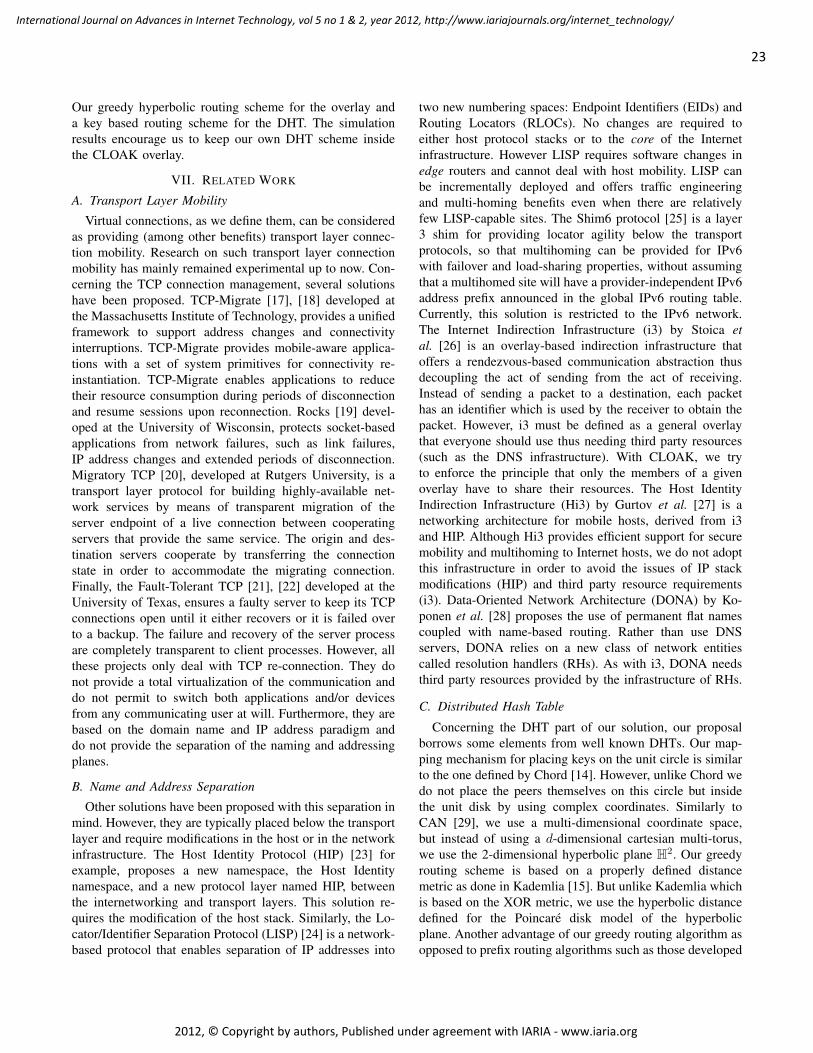
Our greedy hyperbolic routing scheme for the overlay anda key based routing scheme for the DHT. The simulationresults encourage us to keep our own DHT scheme insidethe CLOAK overlay.
VII. RELATED WORK
A. Transport Layer Mobility
Virtual connections, as we define them, can be consideredas providing (among other benefits) transport layer connec-tion mobility. Research on such transport layer connectionmobility has mainly remained experimental up to now. Con-cerning the TCP connection management, several solutionshave been proposed. TCP-Migrate [17], [18] developed atthe Massachusetts Institute of Technology, provides a unifiedframework to support address changes and connectivityinterruptions. TCP-Migrate provides mobile-aware applica-tions with a set of system primitives for connectivity re-instantiation. TCP-Migrate enables applications to reducetheir resource consumption during periods of disconnectionand resume sessions upon reconnection. Rocks [19] devel-oped at the University of Wisconsin, protects socket-basedapplications from network failures, such as link failures,IP address changes and extended periods of disconnection.Migratory TCP [20], developed at Rutgers University, is atransport layer protocol for building highly-available net-work services by means of transparent migration of theserver endpoint of a live connection between cooperatingservers that provide the same service. The origin and des-tination servers cooperate by transferring the connectionstate in order to accommodate the migrating connection.Finally, the Fault-Tolerant TCP [21], [22] developed at theUniversity of Texas, ensures a faulty server to keep its TCPconnections open until it either recovers or it is failed overto a backup. The failure and recovery of the server processare completely transparent to client processes. However, allthese projects only deal with TCP re-connection. They donot provide a total virtualization of the communication anddo not permit to switch both applications and/or devicesfrom any communicating user at will. Furthermore, they arebased on the domain name and IP address paradigm anddo not provide the separation of the naming and addressingplanes.
B. Name and Address Separation
Other solutions have been proposed with this separation inmind. However, they are typically placed below the transportlayer and require modifications in the host or in the networkinfrastructure. The Host Identity Protocol (HIP) [23] forexample, proposes a new namespace, the Host Identitynamespace, and a new protocol layer named HIP, betweenthe internetworking and transport layers. This solution re-quires the modification of the host stack. Similarly, the Lo-cator/Identifier Separation Protocol (LISP) [24] is a network-based protocol that enables separation of IP addresses into
two new numbering spaces: Endpoint Identifiers (EIDs) andRouting Locators (RLOCs). No changes are required toeither host protocol stacks or to the core of the Internetinfrastructure. However LISP requires software changes inedge routers and cannot deal with host mobility. LISP canbe incrementally deployed and offers traffic engineeringand multi-homing benefits even when there are relativelyfew LISP-capable sites. The Shim6 protocol [25] is a layer3 shim for providing locator agility below the transportprotocols, so that multihoming can be provided for IPv6with failover and load-sharing properties, without assumingthat a multihomed site will have a provider-independent IPv6address prefix announced in the global IPv6 routing table.Currently, this solution is restricted to the IPv6 network.The Internet Indirection Infrastructure (i3) by Stoica etal. [26] is an overlay-based indirection infrastructure thatoffers a rendezvous-based communication abstraction thusdecoupling the act of sending from the act of receiving.Instead of sending a packet to a destination, each packethas an identifier which is used by the receiver to obtain thepacket. However, i3 must be defined as a general overlaythat everyone should use thus needing third party resources(such as the DNS infrastructure). With CLOAK, we tryto enforce the principle that only the members of a givenoverlay have to share their resources. The Host IdentityIndirection Infrastructure (Hi3) by Gurtov et al. [27] is anetworking architecture for mobile hosts, derived from i3and HIP. Although Hi3 provides efficient support for securemobility and multihoming to Internet hosts, we do not adoptthis infrastructure in order to avoid the issues of IP stackmodifications (HIP) and third party resource requirements(i3). Data-Oriented Network Architecture (DONA) by Ko-ponen et al. [28] proposes the use of permanent flat namescoupled with name-based routing. Rather than use DNSservers, DONA relies on a new class of network entitiescalled resolution handlers (RHs). As with i3, DONA needsthird party resources provided by the infrastructure of RHs.
C. Distributed Hash Table
Concerning the DHT part of our solution, our proposalborrows some elements from well known DHTs. Our map-ping mechanism for placing keys on the unit circle is similarto the one defined by Chord [14]. However, unlike Chord wedo not place the peers themselves on this circle but insidethe unit disk by using complex coordinates. Similarly toCAN [29], we use a multi-dimensional coordinate space,but instead of using a d-dimensional cartesian multi-torus,we use the 2-dimensional hyperbolic plane H2. Our greedyrouting scheme is based on a properly defined distancemetric as done in Kademlia [15]. But unlike Kademlia whichis based on the XOR metric, we use the hyperbolic distancedefined for the Poincare disk model of the hyperbolicplane. Another advantage of our greedy routing algorithm asopposed to prefix routing algorithms such as those developed
23
International Journal on Advances in Internet Technology, vol 5 no 1 & 2, year 2012, http://www.iariajournals.org/internet_technology/
2012, © Copyright by authors, Published under agreement with IARIA - www.iaria.org

in Pastry [16], is that it does not rely on routing tables. Onlythe coordinates of the neighbors of a peer are needed toforward a message. This is highly scalable as the peers donot need to build and maintain routing tables. The intuitionof using the hyperbolic plane as a virtual address spacefor our overlay and DHT systems comes from the work ofKleinberg [4]. However, we have defined a novel mappingfunction, whereas Kleinberg has suggested using CAN forimplementing a DHT based on hyperbolic coordinates.
VIII. CONCLUSION AND FUTURE WORK
In this paper, we have presented a new architecturecalled CLOAK designed for providing flexibility to Internetcommunications by using virtual connections set upon anoverlay network. This architecture will be implemented astwo protocols running on top of the transport protocols ofthe devices. The devices using the CLOAK middleware willfreely interconnect with each other and thus will form adynamic P2P overlay network. This overlay will enablethe applications to maintain their communications even ifsome transport layer connections are subject to failures. Themiddleware will transparently restore the transport connec-tions without killing the connections of the applications.The architecture, by giving identifiers to users and devices,will provide flexibility, security and mobility to applicationsdespite the IP address changes suffered by the devices.
We have also shown that given an appropriate mappingfunction, it is easy to setup and maintain a consistent DHTstructure upon such an overlay. Our theoretical analysis hasshown that our DHT proposal is scalable with performancessimilar to other existing DHTs. We have implemented theoverlay addressing and routing part as well as the DHTpart of our middleware in our discrete event nem simulatoras well as in the PeerSim simulator and the results areencouraging. Our simulation results have demonstrated thatthe success rate of the routing procedure, as well as thesuccess rate of the storing and solving requests are typicalof such systems. Measurements of path lengths and latenciesalso confirm the proper behavior of our solution comparedto prior ones.
Our future work will be aimed at defining the CLOAKAPI, implementing the middleware as a library, modifying arelevant test application (such as a chat or video streamingapplication) and testing it on a virtualized platform forstudying the impact of transport layer connection pipeliningcreated by the P2P overlay network.
REFERENCES
[1] T. Tiendrebeogo, D. Magoni, and O. Sie, “Virtual internetconnections over dynamic peer-to-peer overlay networks,” inProceedings of the 3rd International Conference on EvolvingInternet, 2011, pp. 58–65.
[2] C. Cassagnes, D. Bromberg, and D. Magoni, “An overlayarchitecture for achieving total flexibility in internet commu-nications,” in Proceedings of the 8th International Confer-ence on Advanced Information Technologies for Management,2010, pp. 39–60.
[3] C. Cassagnes, T. Tiendrebeogo, D. Bromberg, and D. Magoni,“Overlay addressing and routing system based on hyperbolicgeometry,” in Proceedings of the 16th IEEE Symposium onComputers and Communications, 2011, pp. 294–301.
[4] R. Kleinberg, “Geographic routing using hyperbolic space,”in Proceedings of the 26th IEEE INFOCOM, 2007, pp. 1902–1909.
[5] Rosenberg, Schulzrinne, Camarillo, Johnston, and P. et al.,“SIP: Session initiation protocol,” Internet Engineering TaskForce, Request For Comments 3261, June 2002.
[6] ITU-T, “H323: Packet-based multimedia communicationssystems,” ITU-T, Recommendation, December 2009.
[7] J. Postel and J. Reynolds, “File transfer protocol (FTP),”Internet Engineering Task Force, Request For Comments 959,1985.
[8] G. Wright and R. Stevens, TCP/IP Illustrated, Volume 2: TheImplementation. Addison-Wesley, 1995.
[9] E. K. Lua, J. Crowcroft, M. Pias, R. Sharma, and S. Lim,“A survey and comparison of peer-to-peer overlay networkschemes,” IEEE Communications Surveys & Tutorials, vol. 7,pp. 72–93, 2005.
[10] A.-L. Barabasi and E. Bonabeau, “Scale-free networks,” Sci-entific American, vol. 288, pp. 60–69, 2003.
[11] R. Cohen and S. Havlin, “Scale-free networks are ultrasmall,”Phys. Rev. Lett., vol. 90, no. 5, p. 058701, Feb 2003.
[12] D. Magoni, “Network topology analysis and internet mod-elling with nem,” International Journal of Computers andApplications, vol. 27, no. 4, pp. 252–259, 2005.
[13] D. Magoni and M. Hoerdt, “Internet core topology mappingand analysis,” Computer Communications, vol. 28, no. 5, pp.494–506, 2005.
[14] I. Stoica, R. Morris, D. Karger, F. Kaashoek, and H. Balakr-ishnan, “Chord: A scalable peer-to-peer lookup service forinternet applications,” in Proceedings of the ACM SIGCOMMConference, 2001, pp. 149–160.
[15] P. Maymounkov and D. Mazieres, “Kademlia: A peer-to-peerinformation system based on the xor metric,” in Proceedingsof the First International Workshop on Peer-to-Peer Systems(IPTPS). Springer-Verlag, 2002, pp. 53–65.
[16] A. Rowstron and P. Druschel, “Pastry: Scalable, decentralizedobject location and routing for large-scale peer-to-peer sys-tems,” in IFIP/ACM International Conference on DistributedSystems Platforms (Middleware), 2001, pp. 329–350.
[17] A. C. Snoeren, H. Balakrishnan, and M. F. Kaashoek, “Re-considering IP mobility,” in Proceedings of the 8th HotOS,2001, pp. 41–46.
24
International Journal on Advances in Internet Technology, vol 5 no 1 & 2, year 2012, http://www.iariajournals.org/internet_technology/
2012, © Copyright by authors, Published under agreement with IARIA - www.iaria.org

[18] A. Snoeren and H. Balakrishnan, “An end-to-end approachto host mobility,” in Proceedings of the 6th ACM MobiCom,2000, pp. 155–166.
[19] V. Zandy and B. Miller, “Reliable network connections,” inProceedings of the 8th ACM MobiCom, 2002, pp. 95–106.
[20] F. Sultan, K. Srinivasan, D. Iyer, and L. Iftode, “MigratoryTCP: Connection migration for service continuity in theinternet,” in Proceedings of the 22nd International Conferenceon Distributed Computing Systems, 2002, pp. 469–470.
[21] D. Zagorodnov, K. Marzullo, and T. Bressoud, “Engineeringfault tolerant TCP/IP services using FT-TCP,” in Proceedingsof the IEEE International Conference on Dependable Systemsand Networks, 2003, pp. 393–402.
[22] T. Bressoud, A. El-Khashab, K. Marzullo, and D. Zagorod-nov, “Wrapping server-side TCP to mask connection failures,”in Proceedings of the 20th IEEE INFOCOM, 2001, pp. 329–338.
[23] P. Nikander, A. Gurtov, and T. Henderson, “Host identityprotocol (hip): Connectivity, mobility, multi-homing, security,and privacy over ipv4 and ipv6 networks,” IEEE Communi-cations Surveys and Tutorials, vol. 12, no. 2, pp. 186–204,2010.
[24] D. Farinacci, V. Fuller, D. Meyer, and D. Lewis, “Loca-tor/identifier separation protocol,” Internet Engineering TaskForce, Internet Draft, July 2011.
[25] E. Nordmark and M. Bagnulo, “Shim6: Level 3 multihomingshim protocol for IPv6,” Internet Engineering Task Force,Request For Comments 5533, June 2009.
[26] I. Stoica, D. Adkins, S. Zhuang, S. Shenker, and S. Surana,“Internet indirection infrastructure,” in Proceedings of ACMSIGCOMM’02, 2002.
[27] A. Gurtov, D. Korzun, A. Lukyanenko, and P. Nikander, “Hi3:An efficient and secure networking architecture for mobilehosts,” Computer Communications, vol. 31, pp. 2457–2467,2008.
[28] T. Koponen, M. Chawla, B.-G. Chun, A. Ermolinskiy, K. H.Kim, S. Shenker, and I. Stoica, “A data-oriented (and beyond)network architecture,” in Proceedings of the 2007 conferenceon Applications, technologies, architectures, and protocols forcomputer communications, ser. SIGCOMM ’07, 2007, pp.181–192.
[29] S. Ratnasamy, P. Francis, M. Handley, R. Karp, andS. Shenker, “A scalable content-addressable network,” inProceedings of the ACM SIGCOMM Conference, 2001, pp.161–172.
25
International Journal on Advances in Internet Technology, vol 5 no 1 & 2, year 2012, http://www.iariajournals.org/internet_technology/
2012, © Copyright by authors, Published under agreement with IARIA - www.iaria.org

Quality Analysis of a Chaotic Proven Keyed HashFunction
Jacques M. Bahi, Jean-François Couchot, and Christophe GuyeuxUniversity of Franche-Comté, FEMTO-ST Institute
Belfort, FranceEmail: {jacques.bahi, jean-francois.couchot, christophe.guyeux}@univ-fcomte.fr
Abstract—Hash functions are cryptographic tools, which arenotably involved in integrity checking and password storage.They are of primary importance to improve the security ofexchanges through the Internet. However, as security flaws havebeen recently identified in the current standard in this domain,new ways to hash digital data must be investigated. In thisdocument an original keyed hash function is evaluated. It isbased on asynchronous iterations leading to functions that havebeen proven to be chaotic. It thus possesses various topologicalproperties as uniformity and sensibility to its initial condition.These properties make our hash function satisfies establishedsecurity requirements in this field. This claim is qualitativelyproven and experimentally verified in this research work, amongother things by realizing a large number of simulations.
Keywords-Keyed Hash Function; Internet Security; Mathemat-ical Theory of Chaos; Topology.
I. INTRODUCTION
The security and the privacy of data exchanged through theInternet are guaranteed by protocols that make an adequate useof a few cryptographic tools as secure pseudorandom numbergenerators or hash functions. Hash functions are applicationsthat map words of any lengths to words of fixed lengths (often256 or 512 bits). These hash functions allow, for instance, tostore passwords in a secure manner or to check whether adownload has occurred without any error. They be designedto depend from a given parameter, called a key. According totheir field of application, the requirements an hash functionhas to satisfy can change. They need at least to be very fast,so that the diffusion of the digest into the set of hash valuesoccurs (whatever the bias into the inputted message), and sothat a link between a message and its digest is impossibleto establish in practice (confusion). The possibility to usea key or to distribute the computation on numerous threadsmust often be offered in several applications. Finally, in thecomputer security field, stringent complexity properties haveto be proven, namely the collision, preimage, and second-preimage resistances, the unpredictability, and the pseudo-randomness properties. Each of the latter one have a rigorousformulation in terms of polynomial indistinguishability.
Several hash functions have been proposed as candidates tobe standards in computer science. Such standards are designedby the scientific community and selected, after peer studies,by administrations as the NIST one (National Institute forStandards and Technologies of the US government). SHA-1is probably the most widely used hash function. It is presentin a large panel of security applications and protocols throughthe Internet.
However, in 2004, MD5 and SHA-0 have been broken. Anattack over SHA-1 has been achieved with only 269 operations(CRYPTO-2005), that is, 2, 000 times faster than a brute force
attack (that requires 280 operations). Even if 269 operations stillremain impossible to realize on common computers, such a re-sult, based on a previous attack on SHA-0, is a very importantone: as the SHA-2 variants are algorithmically close to SHA-1and eventually produce message digests on principles similarto the MD4 and MD5 message digest algorithms, a new hashstandard based on original approaches is then eagerly awaited.This is why a SHA-3 contest has been launched these last fewyears, to find a new, more secure standard for hash functions.So new original hash functions, or improvements for existingones, must be found.
In this context, we have proposed a new hash function in [1],[2]. Being designed by using discrete dynamical systems, andtaking benefits from various established topological properties,this new family of hash functions is thus based on a completelydifferent approach. Among other things, in our proposal, aningredient of chaos is added to existing hash functions, in orderto reinforce their properties. Introducing chaos into the designof hash functions has been already addressed in [3], [4], [5],[6]. These methods usually transform the initial message intoits padded fixed length version and then translate it into areal number. Next, with a chosen chaotic map (some chaoticfunctions of real variables like logistic, tent, or Arnold’s catmaps, for instance [7]), methods set the initial algorithmparameters according to the secret key and start iterations.Methods are then left to extract some bits from the iterationsresults and to juxtapose them to get the hash value. It is thensupposed that the final hash function preserves the propertiesof chaos. However, the idea of chaotic hash functions has beencontroversially discussed in the community [8], [9]. Moreover,even if these algorithms are themselves proven to be chaotic,their implementations on finite machines can result into theloss of chaos property. Among other things, the main reasonis that chaotic functions (embedded in these researches) onlymanipulate real numbers, which do not exist in a computer.In [2], the hash function we have proposed does not simplyintegrate chaotic maps into algorithms hoping that the resultremains chaotic; we have conceived an algorithm and havemathematically proven that it is chaotic. To do both, our theoryand our implementation are based on finite integer domainsand finite states iterations, where only one randomly chosenelement is modified at each step. This iteration mode is furtherreferred to as asynchronous mode.
These studies lead to the conclusion that the chaos ofasynchronous iterations is very intense [10]. As this modeonly manipulates binary digits or integers, we have shownthat truly chaotic computer programs can be produced. Theycan thus be applied to pseudorandom number generators [11]and to a complete class of information hiding schemes [12],
26
International Journal on Advances in Internet Technology, vol 5 no 1 & 2, year 2012, http://www.iariajournals.org/internet_technology/
2012, © Copyright by authors, Published under agreement with IARIA - www.iaria.org

for instance. In this paper, the complete chaotic behavior ofasynchronous iterations is capitalized to produce a truly chaotickeyed hash function.
This research work is an improvement of a previous articleaccepted at the Third International Conference on EvolvingInternet, INTERNET11 (June 19-24, 2011, Luxembourg) [1].Compared to this research work, the proposed hash function(Section III) has been completely rethought. It appears nowmore as a post-treatment on existing hash functions, to improvetheir security (Sections III, IV), than as a hash function de-signed from scratch. Moreover, the second-preimage resistancehas been proven in Section IV-B and the strict avalanchecriterion has been statistically studied (Section V-C). All theseimprovements lead to obviously better scores for the proposedhash functions, when experimentally evaluating its security.
The remainder of this research work is organized in thefollowing way. In Section II, basic notions concerning asyn-chronous iterations and Devaney’s chaos are recalled. Ourkeyed hash function is presented in Section III. Performanceanalyses are presented in the next two sections: in the first onea qualitative evaluation of this function is outlined, whereas inthe second one it is evaluated experimentally. This researchwork ends by a conclusion section, in which our contributionis summarized and intended future work is mentioned.
II. BACKGROUND SECTION
In this section, we first give definitions of Secure KeyedOne-Way Hash Functions and of the Strict Avalanche Criterion(SAC), which is a property that such a function has to verify.Next we give some recalls on Boolean discrete dynamicalsystems and link them with topological chaos. Finally, weestablish relations between the algorithm properties inheritedfrom topological results and the requirements of Secure KeyedOne-Way Hash Function.
A. Secure Keyed One-Way Hash Function
Definition 1 (Secure Keyed One-Way Hash Function [13])Let Γ and Σ be two alphabets, let k ∈ K be a key in a givenkey space, let l be a natural number, which is the length ofthe output message, and let h : K × Γ+ → Σl be a functionthat associates a message in Σl for each pair of key, word inK × Γ+. The set of all functions h is partitioned into classesof functions {hk : k ∈ K} indexed by a key k and suchthat hk : Γ+ → Σl is defined by hk(m) = h(k,m), i.e., hkgenerates a message digest of length l.
A class {hk : k ∈ K} is a Secure Keyed One-Way HashFunction if it satisfies the following properties:
1) the function hk is keyed one-way. That is,a) Given k and m, it is easy to compute hk(m).b) Without the full knowledge of k, it is• difficult to find m when hk(m) is given; this
property is referred to as preimage resistance;• difficult to find hk(m) when only m is given.
2) The function hk is the keyed collision resistant, that is,without the knowledge of k it is difficult to find twodistinct messages m and m′ s.t. hk(m) = hk(m′). Aweaker version of this property is the second preimageresistance, which is established if for a given m it isdifficult to find another message m′, m 6= m′, such thathk(m) = hk(m′).
3) Images of function hk have to be uniformly distributedin Σl in order to counter statistical attacks.
4) Length l of the produced image has to be larger than128 bits in order to counter birthday attacks [14].
5) Key space size has to be sufficiently large in order tocounter exhaustive key search.
Finally, hash functions have to verify the strict avalanchecriterion defined as follows:
Definition 2 (Strict Avalanche Criterion [15]) Let x andxi, two n-bit, binary vectors, such that x and xi differ only inbit i, 1 6 i 6 n. Let f be the cryptographic transformation(hash function applied on vector of bits for instance). Let ⊕be the exclusive or operator. The f function meets the strictavalanche criterion if and only if the following property isestablished;
∀n. ∀i, j. 1 6 i 6 n ∧ 1 6 j 6 m⇒P((f(x)⊕ f(xi)
)j
= 1)
= 1/2
This means that for any length message, each bit of the digestis independent of modifying one bit in the original message. Inother words, a difference of one bit between two given mediashas to lead to completely different digests.
B. Boolean Discrete Dynamical Systems
Let us first discuss the domain of iterated functions. As far aswe know, no result rules that the chaotic behavior of a functionthat has been theoretically proven on R remains valid on thefloating-point numbers, which is the implementation domain.Thus, to avoid the loss of chaos this research work presentsan alternative, namely to iterate Boolean maps: results thatare theoretically obtained in that domain are preserved duringimplementations. This section recalls facts concerning Booleandiscrete-time dynamical Systems (BS) that are sufficient tounderstand the background of our approach.
Let us denote by Ja; bK the interval of integers: {a, a +1, . . . , b}, where a 6 b. Let n be a positive integer. A Booleandiscrete-time system is a discrete dynamical system definedfrom a Boolean map f : Bn → Bn s.t.
x = (x1, . . . , xn) 7→ f(x) = (f1(x), . . . , fn(x)),
and an iteration scheme: parallel, asynchronous. . . With theparallel iteration scheme, the dynamics of the system aredescribed by xt+1 = f(xt) where x0 ∈ Bn. Let thusFf : J1;nK×Bn to Bn be defined by
Ff (i, x) = (x1, . . . , xi−1, fi(x), xi+1, . . . , xn),
with the asynchronous scheme, the dynamics of the systemare described by xt+1 = Ff (st, xt) where x0 ∈ Bn and s isa strategy, i.e., a sequence in J1;nKN. Notice that this schemeonly modifies one element at each iteration.
Let Gf be the map from X = J1;nKN ×Bn to itself s.t.
Gf (s, x) = (σ(s), Ff (s0, x)),
where σ(s)t = st+1 for all t in N. Notice that the paralleliteration of Gf from an initial point X0 = (s, x0) describes the“same dynamics” as the asynchronous iteration of f inducedby the initial point x0 and the strategy s.
27
International Journal on Advances in Internet Technology, vol 5 no 1 & 2, year 2012, http://www.iariajournals.org/internet_technology/
2012, © Copyright by authors, Published under agreement with IARIA - www.iaria.org
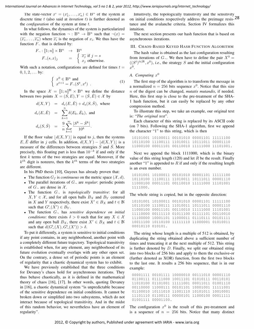
The state-vector xt = (xt1, . . . , xtn) ∈ Bn of the system at
discrete time t (also said at iteration t) is further denoted asthe configuration of the system at time t.
In what follows, the dynamics of the system is particularizedwith the negation function ¬ : Bn → Bn such that ¬(x) =(xi, . . . , xn) where xi is the negation of xi. We thus have thefunction F¬ that is defined by:
F¬ : J1;nK×Bn → Bn
F¬(s, x)j =
{xj if j = sxj otherwise.
With such a notation, configurations are defined for times t =0, 1, 2, . . . by: {
x0 ∈ Bn andxt+1 = F¬(St, xt) .
(1)
In the space X = J1;nKN × Bn we define the distancebetween two points X = (S,E), Y = (S, E) ∈ X by
d(X,Y ) = de(E, E) + ds(S, S), where
de(E, E) =
n∑k=1
δ(Ek, Ek), and
ds(S, S) =9
n
∞∑k=1
|Sk − Sk|10k
.
If the floor value bd(X,Y )c is equal to j, then the systemsE, E differ in j cells. In addition, d(X,Y ) − bd(X,Y )c is ameasure of the differences between strategies S and S. Moreprecisely, this floating part is less than 10−k if and only if thefirst k terms of the two strategies are equal. Moreover, if thekth digit is nonzero, then the kth terms of the two strategiesare different.
In his PhD thesis [10], Guyeux has already proven that:• The function Gf is continuous on the metric space (X , d).• The parallel iterations of G¬ are regular: periodic points
of G¬ are dense in X .• The function G¬ is topologically transitive: for allX,Y ∈ X , and for all open balls BX and BY centeredin X and Y respectively, there exist X ′ ∈ BX and t ∈ Nsuch that Gt
¬(X ′) ∈ BY .• The function G¬ has sensitive dependence on initial
conditions: there exists δ > 0 such that for any X ∈ Xand any open ball BX , there exist X ′ ∈ BX and t ∈ Nsuch that d(Gt
¬(X), Gt¬(X ′)) > δ.
To put it differently, a system is sensitive to initial conditionsif any point contains, in any neighborhood, another point witha completely different future trajectory. Topological transitivityis established when, for any element, any neighborhood of itsfuture evolution eventually overlaps with any other open set.On the contrary, a dense set of periodic points is an elementof regularity that a chaotic dynamical system has to exhibit.
We have previously established that the three conditionsfor Devaney’s chaos hold for asynchronous iterations. Theythus behave chaotically, as it is defined in the mathematicaltheory of chaos [16], [17]. In other words, quoting Devaneyin [16], a chaotic dynamical system “is unpredictable becauseof the sensitive dependence on initial conditions. It cannot bebroken down or simplified into two subsystems, which do notinteract because of topological transitivity. And in the midstof this random behavior, we nevertheless have an element ofregularity”.
Intuitively, the topologically transitivity and the sensitivityon initial conditions respectively address the preimage resis-tance and the avalanche criteria. Section IV formalizes thisintuition.
The next section presents our hash function that is based onasynchronous iterations.
III. CHAOS-BASED KEYED HASH FUNCTION ALGORITHM
The hash value is obtained as the last configuration resultingfrom iterations of G¬. We then have to define the pair X0 =((St)t∈N, x0), i.e., the strategy S and the initial configurationx0.
A. Computing x0
The first step of the algorithm is to transform the message ina normalized n = 256 bits sequence x0. Notice that this sizen of the digest can be changed, mutatis mutandis, if needed.Here, this first step is close to the pre-treatment of the SHA-1 hash function, but it can easily be replaced by any othercompression method.
To illustrate this step, we take an example, our original textis: “The original text”.
Each character of this string is replaced by its ASCII code(on 7 bits). Following the SHA-1 algorithm, first we appendthe character “1” to this string, which is then
10101001 10100011 00101010 00001101 1111110010110100 11100111 11010011 10111011 0000111011000100 00011101 00110010 11111000 11101001.
Next we append the block 1111000, which is the binaryvalue of this string length (120) and let R be the result. Finallyanother “1” is appended to R if and only if the resulting lengthis an even number.
10101001 10100011 00101010 00001101 1111110010110100 11100111 11010011 10111011 0000111011000100 00011101 00110010 11111000 111010011111000.
The whole string is copied, but in the opposite direction:
10101001 10100011 00101010 00001101 1111110010110100 11100111 11010011 10111011 0000111011000100 00011101 00110010 11111000 1110100111110000 00111110 01011100 01111101 0011001011100000 10001101 11000011 01110111 0010111110011100 10110100 11111110 11000001 0101001100010110 010101.
The string whose length is a multiple of 512 is obtained, byduplicating the string obtained above a sufficient number oftimes and truncating it at the next multiple of 512. This stringis further denoted by D. Finally, we split our obtained stringinto two blocks of 256 bits and apply to them the exclusive-or(further denoted as XOR) function, from the first two blocksto the last one. It results a 256 bits sequence, that is in ourexample:
00001111 00101111 10000010 00111010 0000111001100111 01111000 10011101 01010111 0011010111010100 01101001 11111001 00011011 0100111000110000 11000111 00101101 10001001 1111100101100010 10111010 11001110 10101011 1001000111101110 01100111 00000101 11000100 0001111101001111 00001100.
The configuration x0 is the result of this pre-treatment andis a sequence of n = 256 bits. Notice that many distinct
28
International Journal on Advances in Internet Technology, vol 5 no 1 & 2, year 2012, http://www.iariajournals.org/internet_technology/
2012, © Copyright by authors, Published under agreement with IARIA - www.iaria.org

texts lead to the same string x0. The algorithm detailed in [1]always appends “1” to the string R. However such an approachsuffered from generating the same x0 when R’s length is 128.In that case the size of its reverse is again 128 bits leadinga message of length 256. When we duplicate the message,we obtain a message of length 512 composed of two equalmessages. The resulting XOR function is thus 0 and thisimprovement consequently allows us to avoid this drawback.
Let us build now the strategy (St)t∈N that depends on theoriginal message and on a given key.
B. Computing (St)t∈N
To obtain the strategy S, the chaotic proven pseudorandomnumber generator detailed in [18] is used. The seed of thisPRNG is computed as follows: first the ASCII code (on 7bits again) of the key is duplicated enough and truncated tothe length of D. A XOR between D and this chain gives theseed of the PRNG, that is left to generate a finite sequence ofnatural numbers St in J1, nK whose length is 2n.
C. Computing the digest
To design the digest, asynchronous iterations of G¬ arerealized with initial state X0 = ((St)t∈N, x0) as definedabove. The result of these iterations is a n = 256 bits vector.Its components are taken 4 per 4 bits and translated intohexadecimal numbers, to obtain the hash value:
AF71542C90F450F6AE3F649A0784E6B16B788258E87654B4D6353A2172838032.
As a comparison if we replace “The original text” by “theoriginal text”, the hash function returns:
BAD8789AD6924B6460F8E7686A24A4228486DC8FDCAE15F1F681B91311426056.
We then investigate the qualitative properties of this algo-rithm.
IV. QUALITY ANALYSIS
We show in this section that, as a consequence of recalledtheoretical results, this hash function tends to verify desiredinformal properties of a secure keyed one-way hash function.
A. The Strict Avalanche Criterion
In our opinion, this criterion is implied by the topologicalproperties of sensitive dependence to the initial conditions, ex-pansivity, and Lyapunov exponent. These notions are recalledbelow.
First, a function f has a constant of expansivity equal to εif an arbitrarily small error on any initial condition is alwaysmagnified till ε. In our iteration context and more formally,the function G¬ verifies the expansivity property if there existssome constant ε > 0 such that for any X and Y in X , X 6= Y ,we can find a k ∈ N s.t. d(Gk
¬(X), Gk¬(Y )) > ε. We have
proven in [19] that, (X , G¬) is an expansive chaotic system.Its constant of expansivity is equal to 1.
Next, some dynamical systems are highly sensitive to smallfluctuations into their initial conditions. The constants ofsensibility and expansivity have been historically defined toillustrate this fact. However, in some cases, these variationscan become enormous, can grow in an exponential manner in
a few iterations, and neither sensitivity nor expansivity are ableto measure such a situation. This is why Alexander Lyapunovhas proposed a new notion able to evaluate the amplificationspeed of these fluctuations we now recall:
Definition 3 (Lyapunov Exponent) Let be given an iterativesystem x0 ∈ X and xt+1 = f(xt). Its Lyapunov exponent isdefined by:
limt→+∞
1
t
t∑i=1
ln∣∣ f ′ (xi−1)∣∣
By using a topological semi-conjugation between X and R,we have proven in [10] that, for almost all X0, the Lyapunovexponent of asynchronous iterations G¬ with X0 as initialcondition is equal to ln(n).
We can now justify why, in our opinion, the topologicalproperties of the proposed hash function lead to the avalancheeffect. Indeed, due to the sensitive dependence to the initialcondition, two close media can possibly lead to significantlydifferent digests. The expansivity property implies that thesesimilar medias mostly lead to very different hash values.Finally, a Lyapunov exponent greater than 1 leads to the factthat these two close media will always end up by having verydifferent digests.
B. Preimage Resistance
1) Topological Justifications: Let us now discuss about thepreimage resistance of our keyed hash function denoted by h.As recalled previously, an adversary given a target image Dshould not be able to find a preimage M such that h(M) = D.One reason (among many) why this property is important isthat, on most computer systems, users passwords are storedas the cryptographic hash of the password instead of just theplain-text password. Thus an attacker who gains access to thepassword file cannot use it to then gain access to the system,unless it is able to invert target message digest of the hashfunction.
We now explain why, topologically speaking, our hashfunction is resistant to preimage attacks. Let m be the messageto hash, (S, x0) its normalized version (i.e., the initial state ofour iteration scheme), and M = h(m) the digest of m by usingour method. So iterations with initial condition (S,M) anditerate function G¬ have x0 as final state. Thus it is impossibleto invert the hash process with a view to obtain the normalizedmessage by using the digest. Such an attempt is equivalent totry to forecast the future evolution of asynchronous iterationsof the ¬ function by only using a partial knowledge of its initialcondition. Indeed, as M is known but not S, the attacker hasan uncertainty on the initial condition. He/she only knows thatthis value is into an open ball of radius 1 centered at the pointM , and the number of terms of such a ball is infinite.
With such an incertainty on the initial condition, and due tothe numerous chaos properties possessed by our algorithm (asstated in the previous Section), this prediction is impossible.Furthermore, due to the transitivity property, it is possible toreach all of the normalized medias, when starting to iterateinto this open ball. These qualitative explanations can beformulated more rigorously, by the proofs given in the nextsection.
29
International Journal on Advances in Internet Technology, vol 5 no 1 & 2, year 2012, http://www.iariajournals.org/internet_technology/
2012, © Copyright by authors, Published under agreement with IARIA - www.iaria.org
2) Proofs of the Second-Preimage Resistance: We will fo-cus now on a rigorous proof of the second-preimage resistance:an adversary given a message m should not be able to findanother message m′ such that m 6= m′ and h(m) = h(m′).
More precisely, we will show that a more general instanceof the proposed post-treatment described below preserves thischaracter for a given hash function.
Let• k1,k2,n, all in N∗, where k1 is the size of the key, k2 is
the size of the seed, and n is the size of the hash value,• h : (k,m) ∈ Bk1 × B∗ 7−→ h(k,m) ∈ Bn a keyed hash
function,• S : k ∈ Bk2 7−→ S(k) ∈ J1, nK a cryptographically
secure pseudorandom number generator,• K = Bk1 ×Bk2 ×N called the key space,• and f : Bn −→ Bn a bijective map.We define the keyed hash function H : K×B∗ −→ Bn by
the following procedure
Inputs: K = (K1,K2, N) ∈ Km ∈ B∗
Runs: X = h(K1,m)for i = 1, . . . , N :
X = Gf (Si(K2), X)return X
where K1 is the key of the inputted hash function, K2 the seedof the strategy used in the post-treatment iterations, where Nis for the size of this strategy. We have the following result.
Theorem 1 If h satisfies the second-preimage resistance prop-erty, then it is the case for H too.
To achieve the proof, we introduce the two followinglemmas.
Lemma 1 If f : Bn −→ Bn is bijective, then for any S ∈J1, nK, the map Gf,S : x ∈ Bn → Gf ([S, 1, . . . , 1], x)2 ∈ Bn
is bijective too where Gf (_, _)2 is the second term of the pairGf (_, _).
Proof: Since Bn is a finite set, it is sufficient to prove thatGf,S is surjective. Let y = (y1, . . . , yn) ∈ Bn and S ∈ J1, nK.Thus Gf,S
((y1, . . . , yS−1, f
−1(yS), yS+1, . . . , yn))2
=
Gf
([S, 1, . . . , 1], (y1, . . . , yS−1, f
−1(yS), yS+1, . . . , yn))2
=([1, . . . , 1], (y1, . . . , yS−1, yS , yS+1, . . . , yn))2 =(y1, . . . , yS−1, yS , yS+1, . . . , yn) = y. So Gf,S is a surjectivemap between two finite sets and thus bijective.
Lemma 2 Let S ∈ J1, nKN and N ∈ N∗. If f is bijective,then Gf,S,N : x ∈ Bn 7−→ GN
f (S, x)2 ∈ Bn is bijective too.
Proof: Indeed, Gs,f,n = Gf,Sn ◦ . . . ◦ Gf,S0 is bijectiveas a composition of bijective maps (as stated in Lemma 1).
We are now able to prove theorem 1.Proof: Let m, k ∈ B∗ × K. If a message m′ ∈ B∗ can
be found such that H(k,m) = H(k,m′), then, according toLemma 2, h(k1,m) = h(k1,m
′): a second-preimage for h hasthus been found.
C. Algorithm Complexity
In this section the complexity of the above hash function isevaluated for a size l of the media (in bits).
Theorem 2 Let l be the size of the message to hash and n bethe size of its hash value. The algorithm detailed along these
lines requires O(l)+O(n2) elementary operations to producethe hash value.
Proof: In the x0 computation stage only linear operationsover binary tables are achieved. More precisely it first executesone ASCII translation yielding a message of length 7l, a lengthcomputation that increases the message length of log2(7l). Onebit is possibly added. Thus a reversed copy that leads to amessage of length l′ that is 14l+ 2 + 2 log2(7l). The numberof duplication steps to get a message whose length is greaterthan a multiple of 2n is formally given by
mink>1{k | ∃p . p > 1 ∧ k × l′ > 2np} (2)
This number is bounded by
k′ = max{1, n}.
If 14l + 2 + 2 log2(7l) is greater than 2n it is suf-ficient to duplicate the message once. Otherwise, b1 +
2n
14l + 2 + 2 log2(7l)c is greater than
2n
14l + 2 + 2 log2(7l)and
thus l′ × 2n
14l + 2 + 2 log2(7l)is greater than 2n and there
exists a p (p = 1) such that k×l′ > 2np. Thus the minimum of
the set given in Eq.(2) is less than b1+2n
14l + 2 + 2 log2(7l)c,
which is less than n.To sum up, the initialization of x0 requires at most k′ + l′
elementary operations.Let us now detail the S computation step. The number
of elementary operations to provide the seed is boundedby k′ + l′. Next, the embedded PRNG [18], that combinesthe XORShift, xor128, and XORWow PRNGs requires 35elementary operations (17 XOR, 13 rotations, and 5 arithmetic
operations) for generating a 32 bits number and thus 352n
32to
get a number on 2n bits. Furthermore, since the strategy length
is 2n, the computation of S requires at most k′+l′+2n×352n
32,
which is less than k′ + l′ + 5n2.At least, since each iteration modifies only one bit, iterations
require 2n elementary operations.Finally, we have at most 2k′ + 2l′ + 5n2 + 2n elementary
operations to provide a hash value of size n. This bound is inO(l + n2).
V. EXPERIMENTAL EVALUATIONS
Let us now give some examples of hash values beforestatistically studying the quality of hash outputs.
A. Examples of Hash Values
Let us consider the proposed hash function with n = 256.We consider the key to be equal to “my key”. To illustrate theconfusion and diffusion properties [20], we use this functionto generate hash values in the following cases:
Case 1. The original text message is the poem Ulalume(E.A.Poe), which is made of 104 lines, 667 words,and 3, 754 characters.
Case 2. We change serious by nervous in the verse “Ourtalk had been serious and sober”
Case 3. We replace the last point ‘.’ with a coma ‘,’.Case 4. In “The skies they were ashen and sober”, skies
becomes Skies.Case 5. The new original text is the binary value of Figure 1.
30
International Journal on Advances in Internet Technology, vol 5 no 1 & 2, year 2012, http://www.iariajournals.org/internet_technology/
2012, © Copyright by authors, Published under agreement with IARIA - www.iaria.org

Figure 1: The original plain-image.
Case 6. We add 1 to the gray value of the pixel located inposition (123,27).
Case 7. We subtract 1 to the gray value of the pixel locatedin position (23,127).
The corresponding hash values in hexadecimal format are:Case 1. 0B4730459FBB5E54A18A9CCD676C8396
365B0104407D98C866FDAA51A07F0E45,Case 2. 752E28088150B98166D870BC24177342
23A59463D44B83E9808383B30F8B8409,Case 3. C10EED0A9D44856847F533E5647D0CCD
2C58A08643E4D3E5D8FEA0DA0E856760,Case 4. 52BF23429EC3AD16A0C9DE03DF51C420
4466285448D6D73DDFB42E7A839BEE80,Case 5. 5C639A55E2B26861EB9D8EADDF92F935
5B6214ADC01197510586745D47C888B8,Case 6. E48989D48209143BAE306AC0563FFE31
EAB02E5E557B49E3442A840996BECFC1,Case 7. EC850438A2D8EA95E691C746D487A755
12BEE63F4DDB4466C11CD859671DFBEB,These simulation results are coherent with the topological
properties of sensitive dependence to the initial condition,expansivity, and Lyapunov exponent: any alteration in themessage causes a substantial difference in the final hash value.
B. Statistical Evaluation of the Algorithm
We focus now on statistical studies of diffusion and confu-sion properties. Let us recall that confusion refers to the desireto make the relationship between the key and the digest ascomplex and involved as possible, whereas diffusion meansthat the redundancy in the statistics of the plain-text mustbe "dissipated" in the statistics of the cipher-text. Indeed, theavalanche criterion is a modern form of the diffusion, as thisterm means that the output bits should depend on the inputbits in a very complex way.
1) Uniform repartition for hash values: To show the diffu-sion and confusion properties verified by our scheme, we firstgive an illustration of the difference of characters repartitionbetween a plain-text and its hash value, when the originalmessage is again the Ulalume poem. In Figure 2a, (resp.in Figure 2b) the X-axis represents ASCII numbers (resp.hexadecimal numbers) whereas the Y-axis gives for each X-value its position in the original text (resp. in the digest).For instance, in Figure 2b, the point (1, 17) means that thecharacter 1 is present in the digest at position 17 (see Case1, Section. V-A). We can see that ASCII codes are localizedwithin a small area (e.g., the ASCII “space” code and the
0 20 40 60 80 100 120 140ASCII values
0
500
1000
1500
2000
2500
3000
3500
4000
Indi
ces
(a) Original text
0 2 4 6 8 10 12 14 16Hexadecimal values
0
10
20
30
40
50
60
70
Indi
ces
(b) Digest
Figure 2: Values repartition of Ulalume poem
lowercase characters), whereas in Figure 2b the hexadecimalnumbers of the hash value are uniformly distributed.
A similar experiment has been realized with a messagehaving the same size, but which is only constituted by thecharacter “0”. The contrasts between the plain-text messageand its digest are respectively presented in Figures 3a and 3b.Even under this very extreme condition, the distribution of thedigest still remains uniform. To conclude, these simulationstend to indicate that no information concerning the originalmessage can be found into its hash value, as it is recommendedby the Shannon’s diffusion and confusion requirements.
2) Behavior through small random changes: We now con-sider the following experiment. A first message of 1000 bitsis randomly generated, and its hash value of size n = 256bits is computed. Then one bit is randomly toggled into thismessage and the digest of the new message is obtained. Thesetwo hash values are compared by using the hamming distance,to compute the number Bi of changed bits. This test isreproduced t = 10, 000 times. The corresponding distributionof Bi is presented in Figure 4.
As desired, Figure 4 shows that the distribution is centeredaround 128, which reinforces the confidence put into the good
31
International Journal on Advances in Internet Technology, vol 5 no 1 & 2, year 2012, http://www.iariajournals.org/internet_technology/
2012, © Copyright by authors, Published under agreement with IARIA - www.iaria.org

45 46 47 48 49 50 51ASCII values
0
1
2
3
4
5
6
7
Indi
ces
(a) Original text
0 2 4 6 8 10 12 14 16Hexadecimal values
0
10
20
30
40
50
60
70
Indi
ces
(b) Digest
Figure 3: Values repartition of the “00000000” message
9597
99101
103105
107109
111113
115117
119121
123125
127129
131133
135137
139141
143145
147149
151153
155
0
100
200
300
400
500
600
Figure 4: Histogram
capabilities of diffusion and confusion of the proposed hashalgorithm. To analyse these results, the following commonstatistics are used.• Mean changed bit number
B =1
t
t∑i=1
Bi.
Bmin Bmax B P (%) ∆B ∆P (%)
n = 256 87 167 127.95 49.98 8.00 3.13
n = 512 213 306 255.82 49.97 11.29 2.21
n = 1024 446 571 511.54 49.96 15.97 1.56
Table I: Statistical performances of the proposed hash function
• Mean changed probability
P =B
n.
• ∆B =
√1
t
∑ti=1(Bi −B)2.
• ∆P =
√1
t
∑ti=1(Bi
n − P )2.
The obtained statistics are listed in Table I where n belongsto {256; 512; 1, 024}. In that study, starting from a message oflength 1, 000 and its digest, all the messages that have one bitof difference are further generated and the digest of the newmessage is obtained. Obviously, both the mean changed bitnumber B and the mean changed probability P are close to theideal values (n2 bits and 50%, respectively), which illustratesthe diffusion and confusion capability of our algorithm. Lastly,as ∆B and ∆P are very small, these capabilities are verystable.
C. Strict Avalanche Criterion Evaluation
This section focuses on checking whether the developedhash function verifies the strict avalanche criterion, as givenin Definition 2. Quoting remarks of [15], “Unless n is small,it would be an immense task to follow this procedure for allpossible vector pairs x and xi”. The authors propose thus thealternative method of computing a dependence matrix J ofsize m × n between the j-th, 1 6 j 6 m, element of thedigest and i-th, 1 6 i 6 n, element of the original message.A simulation consists in first randomly choosing the size n ofthe message to hash (100 values in J1, 1000K for us). Next, aset of large size r (r = 1, 000 in our case) of messages x israndomly computed. For each of them, the set {x1, . . . , xn}is formed such that x and xi only differ in bit i. The set ofm-bit vectors
{f(x)⊕ f(x1), . . . , f(x)⊕ f(xn)}
is thus computed where f is the hash function applied onvector of bits. The value of bit i (either a 1 or a 0) in
(f(x)⊕
f(xi))j
is added to Jij . Finally each element of J is dividedby r. If every Jij are close to one half, the strict avalanchecriterion is established. For all these experiments, the averagevalue of Jij is 0.5002, the minimal value is 0.418, the maximalvalue is 0.585, and the standard deviation is 0.016.
VI. CONCLUSION
In this research work, the hash function proposed in theThird International Conference on Evolving Internet, INTER-NET11 (June 19-24, 2011, Luxembourg) [1] has been com-pletely rethought. The second-preimage resistance has beenproven, leading to better experimental results for the proposedhash function. Moreover, we have shown that this function has
32
International Journal on Advances in Internet Technology, vol 5 no 1 & 2, year 2012, http://www.iariajournals.org/internet_technology/
2012, © Copyright by authors, Published under agreement with IARIA - www.iaria.org

a complexity that can be expressed as a polynomial functionof the message length and of the digest size. Finally, we havestatistically established that our function verifies the SAC.
If we now consider our approach as an asynchronous itera-tions post-treatment of an existing hash function. The securityof this hash function is reinforced by the unpredictabilityof the behavior of the proposed post-treatment. Thus, theresulting hash function, a combination between an existinghash function and asynchronous iterations, satisfies importantproperties of topological chaos such as sensitivity to initialconditions, uniform repartition (as a result of the transitivity),unpredictability, and expansivity. Moreover, its Lyapunov ex-ponent can be as great as needed. The results expected in ourstudy have been experimentally checked. The choices madein this first study are simple: initial conditions designed byusing the same ingredients as in the SHA-1, negation functionfor the iteration function, etc. But these simple choices haveled to desired results, justifying that such a post-treatment canpossibly improve the security of the inputted hash function.And, thus, such an approach should be investigated morelargely.
This is why, in future work, we will test other choices ofiteration functions and strategies. We will try to characterizetopologically the diffusion and confusion capabilities. Otherproperties induced by topological chaos will be explored andtheir interest for the realization of hash functions will bedeepened. Furthermore, other security properties of resistanceand pseudo-randomness will be proven. We will thus comparethe results of this post-treatment on several hash functions,among other things with the SHA-3 finalists [21].
ACKNOWLEDGMENT
The authors are grateful to the anonymous reviewers fortheir suggestions to improve the quality of the paper.
REFERENCES
[1] J. M. Bahi, J.-F. Couchot, and C. Guyeux, “Performance analysis of akeyed hash function based on discrete and chaotic proven iterations,”in INTERNET 2011, the 3-rd International Conference on EvolvingInternet, Luxembourg, Luxembourg, Jun. 2011, pp. 52–57, best paperaward.
[2] J. M. Bahi and C. Guyeux, “Hash functions using chaotic iterations,”Journal of Algorithms & Computational Technology, vol. 4, no. 2, pp.167–181, 2010.
[3] X.-M. Wang, J.-S. Zhang, and W.-F. Zhang, “One-way hash functionconstruction based on the extended chaotic maps switch,” Acta PhysicaSinica, vol. 52, no. 11, pp. 2737–2742, 2003.
[4] D. Xiao, X. Liao, and Y. Wang, “Improving the security of a parallelkeyed hash function based on chaotic maps,” Physics Letters A, vol. 373,no. 47, pp. 4346–4353, 2009.
[5] ——, “Parallel keyed hash function construction based on chaoticneural network,” Neurocomputing, vol. 72, no. 10-12, pp. 2288–2296,2009, lattice Computing and Natural Computing (JCIS 2007) / NeuralNetworks in Intelligent Systems Designn (ISDA 2007).
[6] D. Xiao, F. Y. Shih, and X. Liao, “A chaos-based hash function with bothmodification detection and localization capabilities,” Communications inNonlinear Science and Numerical Simulation, vol. 15, no. 9, pp. 2254–2261, 2010.
[7] Wikipedia, “List of chaotic maps,” Retrieved June, 2012 from http://en.wikipedia.org/wiki/List_of_chaotic_maps, 2012.
[8] C. song Zhou and T. lun Chen, “Extracting information masked by chaosand contaminated with noise: Some considerations on the security ofcommunication approaches using chaos,” Physics Letters A, vol. 234,no. 6, pp. 429–435, 1997.
[9] W. Guo, X. Wang, D. He, and Y. Cao, “Cryptanalysis on a parallelkeyed hash function based on chaotic maps,” Physics Letters A, vol.373, no. 36, pp. 3201–3206, 2009.
[10] C. Guyeux, “Le désordre des itérations chaotiques et leur utilité ensécurité informatique,” Ph.D. dissertation, Université de Franche-Comté,2010.
[11] J. M. Bahi, J.-F. Couchot, C. Guyeux, and Q. Wang, “Class oftrustworthy pseudo random number generators,” in INTERNET 2011,the 3-rd International Conference on Evolving Internet, Luxembourg,Luxembourg, Jun. 2011, pp. 72–77.
[12] J. M. Bahi, J.-F. Couchot, and C. Guyeux, “Steganography: A class ofsecure and robust algorithms,” The Computuer Journal, vol. 55, no. 6,pp. 653–666, 2012.
[13] S. Bakhtiari, R. Safavi-Naini, and J. Pieprzyk, “Keyed hash functions,”in Cryptography: Policy and Algorithms, ser. Lecture Notes in ComputerScience. Springer-Verlag, 1996, vol. 1029, pp. 201–214.
[14] D. Coppersmith, “Another birthday attack,” in CRYPTO, ser. LectureNotes in Computer Science, H. C. Williams, Ed., vol. 218. Springer,1985, pp. 14–17.
[15] A. F. Webster and S. E. Tavares, “On the design of s-boxes,” in Advancesin Cryptology, ser. CRYPTO ’85. London, UK, UK: Springer-Verlag,1986, pp. 523–534.
[16] R. L. Devaney, An Introduction to Chaotic Dynamical Systems, 2ndEdition. Boulder, CO: Westview Press, March 2003.
[17] C. Knudsen, “Chaos without nonperiodicity,” The American Mathemat-ical Monthly, vol. 101, pp. 563–565, 1994.
[18] J. M. Bahi, R. Couturier, C. Guyeux, and P.-C. Héam, “Efficient andcryptographically secure generation of chaotic pseudorandom numberson gpu,” CoRR, vol. abs/1112.5239, 2011.
[19] C. Guyeux, N. Friot, and J. Bahi, “Chaotic iterations versus spread-spectrum: chaos and stego security,” in Sixth International Conference onIntelligent Information Hiding and Multimedia Signal Processing (IIH-MSP 2010), Darmstadt, Germany. Washington, DC: IEEE ComputerSociety, Oct. 2010, pp. 208–211.
[20] C. E. Shannon, “Communication theory of secrecy systems,” Bell Sys-tems Technical Journal, vol. 28, pp. 656–715, 1949.
[21] M. S. Turan, R. Perlner, L. E. Bassham, W. Burr, D. Chang, S. jenChang, M. J. Dworkin, J. M. Kelsey, S. Paul, and R. Peralta, “Statusreport on the second round of the sha-3 cryptographic hash algorithmcompetition,” National Institute of Standards and Technology, Tech.Rep. NIST Interagency Report 7764, february 2011, retrieved June,2012 from http://csrc.nist.gov/groups/ST/hash/sha-3/Round2/documents/Round2_Report_NISTIR_7764.pdf.
33
International Journal on Advances in Internet Technology, vol 5 no 1 & 2, year 2012, http://www.iariajournals.org/internet_technology/
2012, © Copyright by authors, Published under agreement with IARIA - www.iaria.org
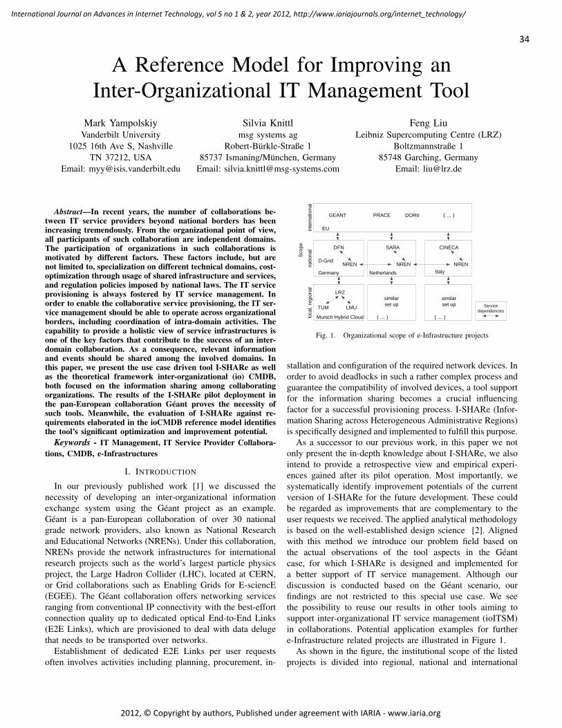
A Reference Model for Improving anInter-Organizational IT Management Tool
Mark YampolskiyVanderbilt University
1025 16th Ave S, NashvilleTN 37212, USA
Email: [email protected]
Silvia Knittlmsg systems ag
Robert-Bürkle-Straße 185737 Ismaning/München, Germany
Email: [email protected]
Feng LiuLeibniz Supercomputing Centre (LRZ)
Boltzmannstraße 185748 Garching, Germany
Email: [email protected]
Abstract—In recent years, the number of collaborations be-tween IT service providers beyond national borders has beenincreasing tremendously. From the organizational point of view,all participants of such collaboration are independent domains.The participation of organizations in such collaborations ismotivated by different factors. These factors include, but arenot limited to, specialization on different technical domains, cost-optimization through usage of shared infrastructure and services,and regulation policies imposed by national laws. The IT serviceprovisioning is always fostered by IT service management. Inorder to enable the collaborative service provisioning, the IT ser-vice management should be able to operate across organizationalborders, including coordination of intra-domain activities. Thecapability to provide a holistic view of service infrastructures isone of the key factors that contribute to the success of an inter-domain collaboration. As a consequence, relevant informationand events should be shared among the involved domains. Inthis paper, we present the use case driven tool I-SHARe as wellas the theoretical framework inter-organizational (io) CMDB,both focused on the information sharing among collaboratingorganizations. The results of the I-SHARe pilot deployment inthe pan-European collaboration Géant proves the necessity ofsuch tools. Meanwhile, the evaluation of I-SHARe against re-quirements elaborated in the ioCMDB reference model identifiesthe tool’s significant optimization and improvement potential.
Keywords - IT Management, IT Service Provider Collabora-tions, CMDB, e-Infrastructures
I. INTRODUCTION
In our previously published work [1] we discussed thenecessity of developing an inter-organizational informationexchange system using the Géant project as an example.Géant is a pan-European collaboration of over 30 nationalgrade network providers, also known as National Researchand Educational Networks (NRENs). Under this collaboration,NRENs provide the network infrastructures for internationalresearch projects such as the world’s largest particle physicsproject, the Large Hadron Collider (LHC), located at CERN,or Grid collaborations such as Enabling Grids for E-sciencE(EGEE). The Géant collaboration offers networking servicesranging from conventional IP connectivity with the best-effortconnection quality up to dedicated optical End-to-End Links(E2E Links), which are provisioned to deal with data delugethat needs to be transported over networks.
Establishment of dedicated E2E Links per user requestsoften involves activities including planning, procurement, in-
LRZ
TUM LMU
NREN
GEANT PRACE
CINECADFN
loca
l, re
gion
alna
tiona
lin
tern
atio
nal
Sco
pe
EU
Germany
Munich Hybrid Cloud
NREN
Italy
SARA
similar set up
( … )
NREN
Netherlands
similar set up
( … )
DORII ( … )
D-Grid
Service dependencies
Fig. 1. Organizational scope of e-Infrastructure projects
stallation and configuration of the required network devices. Inorder to avoid deadlocks in such a rather complex process andguarantee the compatibility of involved devices, a tool supportfor the information sharing becomes a crucial influencingfactor for a successful provisioning process. I-SHARe (Infor-mation Sharing across Heterogeneous Administrative Regions)is specifically designed and implemented to fulfill this purpose.
As a successor to our previous work, in this paper we notonly present the in-depth knowledge about I-SHARe, we alsointend to provide a retrospective view and empirical experi-ences gained after its pilot operation. Most importantly, wesystematically identify improvement potentials of the currentversion of I-SHARe for the future development. These couldbe regarded as improvements that are complementary to theuser requests we received. The applied analytical methodologyis based on the well-established design science [2]. Alignedwith this method we introduce our problem field based onthe actual observations of the tool aspects in the Géantcase, for which I-SHARe is designed and implemented fora better support of IT service management. Although ourdiscussion is conducted based on the Géant scenario, ourfindings are not restricted to this special use case. We seethe possibility to reuse our results in other tools aiming tosupport inter-organizational IT service management (ioITSM)in collaborations. Potential application examples for furthere-Infrastructure related projects are illustrated in Figure 1.
As shown in the figure, the institutional scope of the listedprojects is divided into regional, national and international
34
International Journal on Advances in Internet Technology, vol 5 no 1 & 2, year 2012, http://www.iariajournals.org/internet_technology/
2012, © Copyright by authors, Published under agreement with IARIA - www.iaria.org

levels. The arrows indicate dependencies both within (e.g.,NREN to NREN) and between the layers (e.g., Géant toDFN to LRZ). The Leibniz Supercomputing Centre (LRZ)for example is involved in e-Infrastructure projects on everylevel, like the Munich Hybrid Cloud environment on the locallevel with participation of the Munich universities (LMU,TUM), Grid projects (D-Grid) on the national or the Géantand PRACE project on the international level (see also [3][4]).In other countries similar institutional setups can be found.These listed projects have been previously strictly focusedon operational aspects. With ever-increasing number of userbase and scope, ioITSM issues become more compelling.Thus, a professionally operated IT service management withappropriate tool support is needed more than ever.
The rest of this paper is organized as follows: after giving arather detailed discussion on a case study based on the Géantproject in Section II, we outline our tool concept to assistioITSM in Section III. This concept is mainly based on theresults described in [5] and can be used as a reference modelto either build a new tool from scratch or to evaluate existingtools according to their possible usage as an ioCMDB. We thendiscuss the latter aspect in Section IV. Our discussion mainlyconcentrates on a systematic analysis of an inter-organizationalmanagement approach developed in the Géant project. A briefsurvey on the related work is provided in Section V. Weconclude this paper with a perspective for the future workin Section VI.
II. CASE STUDY: I-SHARE IN GÉANT
In this section we first outline the challenges by establishingand operating Géant network service E2E Links. Then wepresent an information sharing tool called I-SHARe, whichis developed in the Géant project to support and coordi-nate manual handling processes of multi-domain E2E Links.We conclude this section with a discussion of experiencesgained during the pilot operation with I-SHARe and ourfurther development plan. The discussion provides the basisfor the understanding of the challenges faced by the inter-organizational information sharing tools.
A. Géant Service E2E Links
The purpose of Géant is to interconnect NRENs andtherefore to foster international research projects, in whichparticipating organizations are connected through differentNRENs. The portfolio of Géant includes various servicesamong others conventional IP connections. However, suchservices cannot always fulfill all the challenging requirementsof modern research collaborations. One of the most prominentexamples of such a challenge is the Large Hadron Collider(LHC) project, which produces over 15 petabytes of rawexperimental data per year [6] and related Worldwide LHCComputing Grid (WLCG) [7] built with the purpose of dataprocessing and analyzing for the LHC experiment.
For a dependable and robust operation, such projects oftenrely on network connections with rigorous quality assurance.Realizing high-quality high-bandwidth connections in general
purpose IP networks is a challenging task, many reasonscan deteriorate network quality, for example communicationflows can interfere with each other and lead to an inferiorconnection quality. In order to cope with user’s challengingdemands, a novel End-to-End (E2E) Link service has beenintroduced in Géant. E2E Links are dedicated optical point-to-point connections realized at ISO/OSI layers 1 and 2, withconnection segments provided by one or more NRENs [8].An E2E Link across multiple domains differentiates from itssingle domain counterpart in its quality requirements, varietyon the participating networking technologies and geographicaldimensions. E2E Links are multi-domain backbone connec-tions, in which – in opposite to classical backbones – multiplenetwork providers are involved and heterogeneous networktechnologies can be used. The E2E Link structure is presentedin Figure 2 in principle.
Domain 1
Domain 2
Domain 3
(native Ethernet)
(Ethernet
over SDH)
(Ethernet over MPLS)
Segment 1: IEEE 802.1Q VLAN
Segment 2: SDH path (using GFP-F)
Segment 2: MPLS LSP
EndPoint A
EndPoint B
E2E Link A-B
Fig. 2. Typical E2E Link Structure [9]
A main feature of a multi-domain E2E Link service is thata new connection can be requested and ordered independentlyfrom the actual availability status of required infrastructures.If a new infrastructure is needed to sustain the customer’srequest, it can be procured, installed, and configured accordingto the corresponding requirements of the new E2E Link.Consequently, all route planning procedures can only be donemanually and require intensive interactions and task trackingsbetween the involved NRENs.
Empirical experiences gained during the first years of theE2E Link service has revealed that exchanging and main-taining connectivity information determine the time efficiencyof planning and installation of a particular E2E Link acrossdomains. Information exchange via e-mail and planning viaExcel sheets has proven to be error prone with a high proba-bility of information losses or missing events, e.g., the deliveryof the procured infrastructure by neighboring NRENs. Thiscauses a high fluctuation on the time needed to plan and installnew links. In order to improve this situation, a tool supportingthe information exchange among participating NRENs wasintroduced for the E2E Links service.
B. Sharing Information with I-SHARe
The design and development of the I-SHARe tool has beenperformed by an international team of researchers working fordifferent NRENs. I-SHARe covers information exchange for
35
International Journal on Advances in Internet Technology, vol 5 no 1 & 2, year 2012, http://www.iariajournals.org/internet_technology/
2012, © Copyright by authors, Published under agreement with IARIA - www.iaria.org
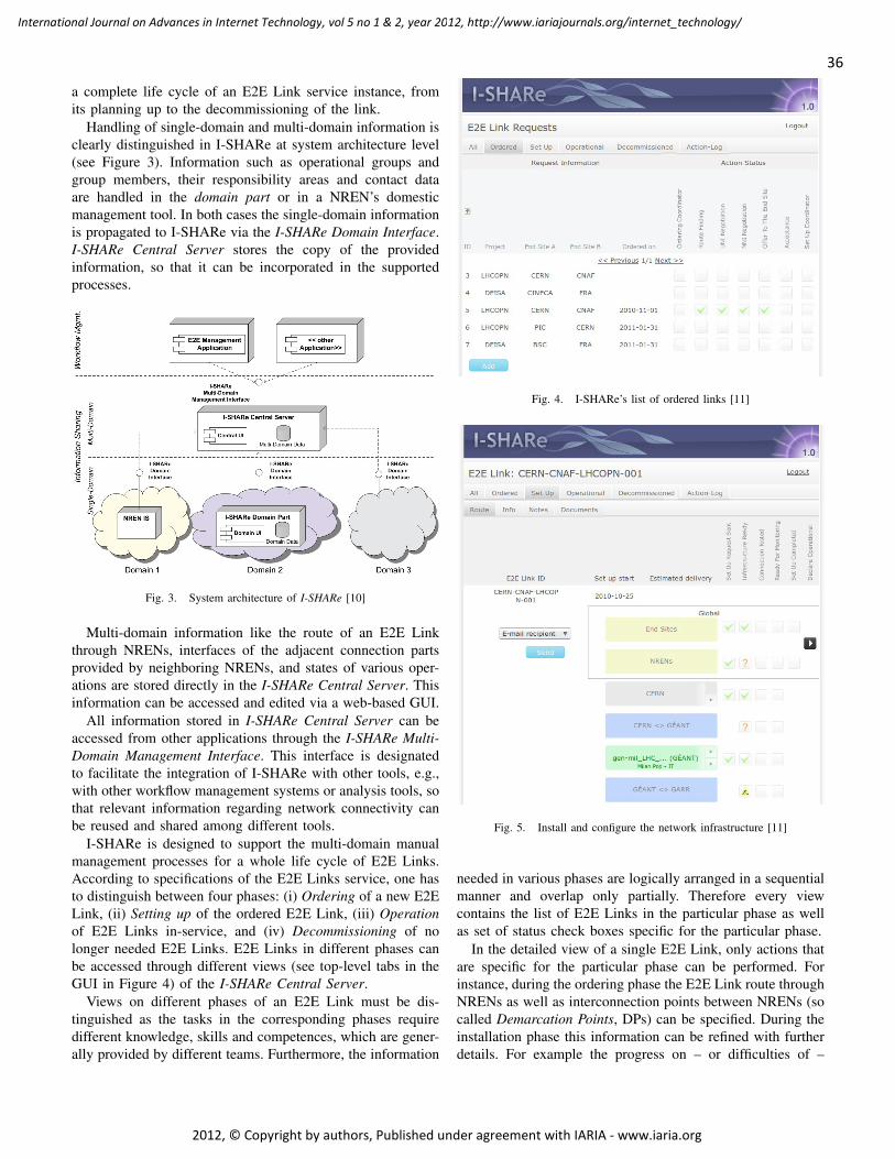
a complete life cycle of an E2E Link service instance, fromits planning up to the decommissioning of the link.
Handling of single-domain and multi-domain information isclearly distinguished in I-SHARe at system architecture level(see Figure 3). Information such as operational groups andgroup members, their responsibility areas and contact dataare handled in the domain part or in a NREN’s domesticmanagement tool. In both cases the single-domain informationis propagated to I-SHARe via the I-SHARe Domain Interface.I-SHARe Central Server stores the copy of the providedinformation, so that it can be incorporated in the supportedprocesses.
Fig. 3. System architecture of I-SHARe [10]
Multi-domain information like the route of an E2E Linkthrough NRENs, interfaces of the adjacent connection partsprovided by neighboring NRENs, and states of various oper-ations are stored directly in the I-SHARe Central Server. Thisinformation can be accessed and edited via a web-based GUI.
All information stored in I-SHARe Central Server can beaccessed from other applications through the I-SHARe Multi-Domain Management Interface. This interface is designatedto facilitate the integration of I-SHARe with other tools, e.g.,with other workflow management systems or analysis tools, sothat relevant information regarding network connectivity canbe reused and shared among different tools.
I-SHARe is designed to support the multi-domain manualmanagement processes for a whole life cycle of E2E Links.According to specifications of the E2E Links service, one hasto distinguish between four phases: (i) Ordering of a new E2ELink, (ii) Setting up of the ordered E2E Link, (iii) Operationof E2E Links in-service, and (iv) Decommissioning of nolonger needed E2E Links. E2E Links in different phases canbe accessed through different views (see top-level tabs in theGUI in Figure 4) of the I-SHARe Central Server.
Views on different phases of an E2E Link must be dis-tinguished as the tasks in the corresponding phases requiredifferent knowledge, skills and competences, which are gener-ally provided by different teams. Furthermore, the information
Fig. 4. I-SHARe’s list of ordered links [11]
Fig. 5. Install and configure the network infrastructure [11]
needed in various phases are logically arranged in a sequentialmanner and overlap only partially. Therefore every viewcontains the list of E2E Links in the particular phase as wellas set of status check boxes specific for the particular phase.
In the detailed view of a single E2E Link, only actions thatare specific for the particular phase can be performed. Forinstance, during the ordering phase the E2E Link route throughNRENs as well as interconnection points between NRENs (socalled Demarcation Points, DPs) can be specified. During theinstallation phase this information can be refined with furtherdetails. For example the progress on – or difficulties of –
36
International Journal on Advances in Internet Technology, vol 5 no 1 & 2, year 2012, http://www.iariajournals.org/internet_technology/
2012, © Copyright by authors, Published under agreement with IARIA - www.iaria.org

installation can be specified for every single interface (seeFigure 5).
One of the most important advantages of I-SHARe isthe possibility to coordinate efforts between NRENs. As allNRENs are independent organizations and often use hardwarefrom different vendors and/or prefer different network tech-nology, the compatibility of interconnected interfaces becomesone of the most critical factors.
Even if I-SHARe is designed as an information exchangerather than a workflow tool, however, some operation logicrestrictions are already integrated. For instance, the buttonfor declaring an E2E Link operational becomes enabled onlyafter checkboxes of all involved interfaces are set to the stateindicating that the setup is completed.
C. I-SHARe: Empirical Experiences and Future Plans
A detailed description of I-SHARe version 1.0 can be foundin [1][10]. After the initial release in 2010, a user survery hasbeen conducted among seleted NRENs during the pilot phaseof operation. Feedbacks obtained from participating NRENsshow a high acceptance of I-SHARe for its functionalities andusabilities. However, the survey also reveals several deficien-cies that the users wish to be improved in the next version[12].
Improvementsnot needed
Workflowsupport
Tool Integration Otherimprovements
0%
50%
75% 75%
Fig. 6. Survey result on user requested improvements [12]
Among the requested I-SHARe improvements workflowsupport and tool integration are weighted as the most importantfeature (see Figure 6). As I-SHARe is a supporting tool, itshould be flexible enough to sustain established workflows inthe project. It also implies that the tool should be adaptive tochanging workflows, which is a common case as shown byempirical experiences. For instance, during the time elapsedfrom the requirements analysis until the deployment of the toolin its pilot phase, the role model used in manual workflowshas been changed. This change has introduced the necessityto change the role model implemented in I-SHARe.
Tool integration is a further critical issue that requirescareful consideration. As I-SHARe supports manual processes,it should prevent users from the daunting tasks of re-enteringsame data in different tools. A technical solution for this prob-lem is an extended communication interface. This interfaceshould allow external tools to communicate with I-SHARe
V2.0 in order to access existing or publish new data. Forinstance, it is planned that the E2E Link monitoring softwareE2Emon [13] will access the information about physical linksfrom I-SHARe. In contrast, in the future it should be alsopossible to propagate the information about planned E2ELink segment maintenance from NREN-internal tools to theI-SHARe so that this information can be seen and consideredin the multi-domain planning.
The pilot survey has also disclosed the necessity for sev-eral new features that were not identified during the initialrequirements analysis process. For instance, in I-SHARe V2.0a further communication capability should be implemented,so that stakeholders of a particular links can be automaticallyinformed about the current status via e-mail notification incases of network anomalies. This feature allowss I-SHARe toprovide assistance to the manual management processes evenif the network operators are not necessarily logged into thetool.
III. IOCMDB REFERENCE MODEL
Motivated by the aformentioned use case, there is a com-pelling need for a tool support of ioITSM. I-SHARe isdesigned and developed to address such needs. In orderto systematically identify and formally derive improvementpotentials of I-SHARe, in this section we apply a referencemodel of ioCMDB based on the concept discussed in [5].This concept is fully in alignment to de-facto standards ofITSM, such as IT Infrastructure Library (ITIL, see: [14] andSection V). As suggested by ITIL, a Configuration Man-agement Database (CMDB) acts as an information nexus toprovide relevant management information to all disciplines ofITSM. The entities stored in a CMDB are Configuration Items(CI), which represent information about software, hardware,services, related documents and their corresponding interrela-tions. A readily available information repository as such willgreatly improve the efficiency of IT management. Incidentmanagement, for example, uses specifications of CI prioritiesfor the controlling of waiting queues, Change management isable to anticipate the impact of planed changes on potentiallyaffected CI by having an overview of the CI relationships, andAvailability management is able to identify the occurrence ofsingle points of failures [15].
Whereas the conventional CMDB concept is well-studiedand mature for IT services in a single organization, a compar-ative approach need to be elaborated and advised to take inter-organizational aspect into consideration. Our efforts towardthis kind of approach is called inter-organizational CMDB(ioCMDB).
The applied research method is based on the principlesof design science [2], which is a formal approach to buildartifacts. Our claim is to create a reference model of anioCMDB. As a reference model possesses both descriptive aswell as prescriptive characteristics, the requirements identifiedwithin the design process in [5] will be used as a basisfor the evaluation of I-SHARe. This evaluation will showwhether I-SHARe is an appropriate tool to serve the purpose of
37
International Journal on Advances in Internet Technology, vol 5 no 1 & 2, year 2012, http://www.iariajournals.org/internet_technology/
2012, © Copyright by authors, Published under agreement with IARIA - www.iaria.org
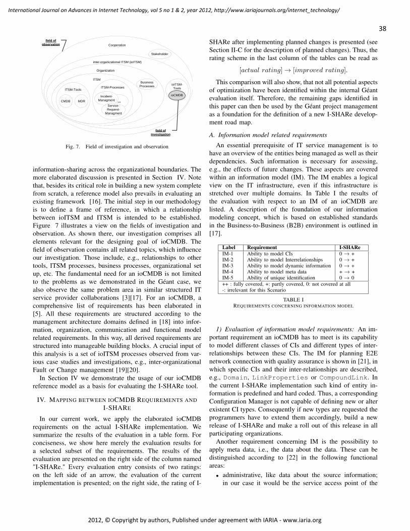
Cooperation
inter-organizational ITSM (ioITSM)
Organization
ITSM
ITSM-Tools
CMDB MDR
ITSM-Processes
...Incident-
Managment
Service-Request-
Managment
Business Processes ioITSM-
Tools
ioCMDB
Stakeholder
field of observation
field of investigation
Fig. 7. Field of investigation and observation
information-sharing across the organizational boundaries. Themore elaborated discussion is presented in Section IV. Notethat, besides its critical role in building a new system completefrom scratch, a reference model also prevails in evaluating anexisting framework [16]. The initial step in our methodologyis to define a frame of reference, in which a relationshipbetween ioITSM and ITSM is intended to be established.Figure 7 illustrates a view on the fields of investigation andobservation. As shown there, our investigation comprises allelements relevant for the designing goal of ioCMDB. Thefield of observation contains all related topics, which influenceour investigation. Those include, e.g., relationships to othertools, ITSM processes, business processes, organizational setup, etc. The fundamental need for an ioCMDB is not limitedto the problems as we demonstrated in the Géant case, wealso observe the same problem area in similar structured ITservice provider collaborations [3][17]. For an ioCMDB, acomprehensive list of requirements has been elaborated in[5]. All these requirements are structured according to themanagement architecture domains defined in [18] into infor-mation, organization, communication and functional modelrelated requirements. In this way, all derived requirements arestructured into manageable building blocks. A crucial input ofthis analysis is a set of ioITSM processes observed from var-ious case studies and investigations, e.g., inter-organizationalFault or Change management [19][20].
In Section IV we demonstrate the usage of our ioCMDBreference model as a basis for evaluating the I-SHARe tool.
IV. MAPPING BETWEEN IOCMDB REQUIREMENTS ANDI-SHARE
In our current work, we apply the elaborated ioCMDBrequirements on the actual I-SHARe implementation. Wesummarize the results of the evaluation in a table form. Forconciseness, we show here merely the evaluation results fora selected subset of the requirements. The results of theevaluation are presented on the right side of the column named"I-SHARe." Every evaluation entry consists of two ratings:on the left side of an arrow, the evaluation of the currentimplementation is presented; on the right side, the rating of I-
SHARe after implementing planned changes is presented (seeSection II-C for the description of planned changes). Thus, therating scheme in the last column of the tables can be read as
[actual rating] → [improved rating].
This comparison will also show, that not all potential aspectsof optimization have been identified within the internal Géantevaluation itself. Therefore, the remaining gaps identified inthis paper can then be used by the Géant project managementas a foundation for the definition of a new I-SHARe develop-ment road map.
A. Information model related requirements
An essential prerequisite of IT service management is tohave an overview of the entities being managed as well as theirdependencies. Such information is necessary for assessing,e.g., the effects of future changes. These aspects are coveredwithin an information model (IM). The IM enables a logicalview on the IT infrastructure, even if this infrastructure isstretched over multiple domains. In Table I the results ofthe evaluation with respect to an IM of an ioCMDB arelisted. A description of the foundation of our informationmodeling concept, which is based on established standardsin the Business-to-Business (B2B) environment is outlined in[17].
Label Requirement I-SHAReIM-1 Ability to model CIs 0 → +IM-2 Ability to model Interrelationships 0 → +IM-3 Ability to model dynamic information 0 → +IM-4 Ability to model meta data + → +IM-5 Ability of unique identification 0 → 0++ : fully covered, +: partly covered, 0: not covered at all-: irrelevant for this Scenario
TABLE IREQUIREMENTS CONCERNING INFORMATION MODEL
1) Evaluation of information model requirements: An im-portant requirement an ioCMDB has to meet is its capabilityto model different classes of CIs and different types of inter-relationships between these CIs. The IM for planning E2Enetwork connection with quality assurance is shown in [21], inwhich specific CIs and their inter-relationships are described,e.g., Domain, LinkProperties or CompoundLink. Inthe current I-SHARe implementation such kind of entity in-formation is predefined and hard coded. Thus, a correspondingConfiguration Manager is not capable of defining new or alterexistent CI types. Consequently if new types are requested theprogrammers have to extend them accordingly, build a newrelease of I-SHARe and make a roll out of this release in allparticipating organizations.
Another requirement concerning IM is the possibility toapply meta data, i.e., the data about the data. These can bedistinguished according to [22] in the following functionalareas:
• administrative, like data about the source information;in our case it would be the service access point of the
38
International Journal on Advances in Internet Technology, vol 5 no 1 & 2, year 2012, http://www.iariajournals.org/internet_technology/
2012, © Copyright by authors, Published under agreement with IARIA - www.iaria.org

connected domain specific CMDB or rather any otherManagement Data Repository (MDR),
• descriptive, e.g., annotations by users,• preservation, like data refreshing cycles,• technical, as for example data related to how a system
functions like it’s software documentation,• use, metadata related to the level and type of use of
information resources, like log files.In the actual I-SHARe release, meta data used for furtherdescription of extrinsic or intrinsic features of CIs like owneror status lifecycle are hard coded and thus, evaluated to ’partlyapplicable’ in Table I.
2) Identified improvements in information modeling: Theneed for being flexible in defining dedicated CI classes hasbeen identified as an action item to be implemented in thenext release of I-SHARe. However, in contrast to our ioCMDBrequirement for having an explicit role model, i.e., for the roleof an inter-organizational Configuration Manager, any personis allowed to create CI types. As it is assumed presently thatthe tool is operated in a environment of dedicated services, cur-rently such CI types are only representing the type interface.Thus, the evaluation remains on ’partly applicable’. Accordingto our concept, a more dynamic modeling means must be im-plemented in I-SHARe to support various cross-organizationalscenarios and services. In the actual improvement plan, theneed for having meta data in place to improve the I-SHARe’soperational capabilities is not recognized. This is the reason,for which the rating will remain the same for the next plannedrelease cycle.
B. Organizational model related requirements
While IM addresses the modeling aspects of CIs and theirrelations, the focus of an organizational model (OM) layson the governance structure. This is especially importantfor our intended use cases of cross-organizational providercollaborations. Thus, OM aspects have to be reflected in anioCMDB. The requirements for a mapping of this structure aswell as the adequate mapping of the user’s roles are met to ahigh degree by the actual implementation of I-SHARe as canbe seen in Table II.
Label Requirement I-SHAReOM-1 Mapping of the governance structure + → +OM-2 Mapping of roles/users + → +++: fully covered, +: partly covered, 0: not covered at all-: irrelevant for this scenario
TABLE IIREQUIREMENTS CONCERNING ORGANIZATIONAL MODEL
1) Evaluation of organizational model requirements: Thegovernance structure within the actual I-SHARe release allowsmapping users to groups and groups to roles. These roles arehard coded. Thus, this fact is rated as ’partly covered’. Due toorganizational changes in such environments the correspond-ing governance structure might change as well. This aspecthas not yet been addressed within the project.
2) Identified improvements in organizational model: Theneed for having roles in place for enabling a dedicated man-agement of controlling issues has been identified also withinthe project itself. The actual release planning in the I-SHAReproject is discussing the implementation of a transaction basedrole model. This will allow a transaction and role basedlogging, which again permits analyzing of log files. But hereagain, the role model itself will remain hard coded, andwon’t be changeable on a flexible base as suggested by ourrequirement catalogue.
C. Communication model related requirements
The mechanism, how management information are ex-changed between the ioCMDB and related local CMDBs aresubject of the communication model. In Table III the require-ments concerning communication mechanism are shown.
1) Evaluation of communication model requirements: Oneimportant issue is the channels the exchanged messages ofmanagement information are taking. It is a requirement, thatsuch channels can be specified according to the correspondingneed. We will further describe the interaction characteristic inmore detail in future work. At the moment, this requirementis not fulfilled completely by the actual I-SHARe release.This leads to the fact, that I-SHARe cannot support ioITSMprocesses efficiently. At present the requirement KM-2 forhaving web based communication means is fully covered byusing e-mail and web services. Although, there is no wayto define the communication characteristics as requested byrequirement KM-4. Having a registry mechanism in place,where new or changed members or roles can be registeredis of minor relevance for this scenario, since we are facing astable organizational structure and its changes is the matter oflong term planning.
Label Requirement I-SHAReKM-1 registry -KM-2 web based communication ++KM-3 define direction of communication 0 → ++KM-4 define communication mechanism 0 → +++: fully covered, +: partly covered, 0: not covered at all-: irrelevant for this scenario
TABLE IIIREQUIREMENTS CONCERNING COMMUNICATION MODEL
2) Identified improvements in communication modeling:According to the actual I-SHARe release planning, it isintended to send messages containing information about, e.g.,state changes of inter-organizational relevant CI like the statusof an E2E Link within the order process via e-mail to allparticipating members within Géant. The disadvantage of sucha mechanism is a potential information flooding of all therecipients instead of informing only the affected responsiblepersons, resulting in rather ignoring such e-mails than reactingconsequently.
Due to the requirements identified in [5] it should be possi-ble to define both the direction of the communication and themechanism, i.e., in case of state changes only the responsible
39
International Journal on Advances in Internet Technology, vol 5 no 1 & 2, year 2012, http://www.iariajournals.org/internet_technology/
2012, © Copyright by authors, Published under agreement with IARIA - www.iaria.org

roles should be informed via appropriate mechanism, whichcan be for example alerts or warning e-mails. The needfor defining the communications directions, e.g., informationprovided by a local partner, that is propagated to I-SHAReand from there to relevant recipients in other organizationshas also been identified as an open issue in the project. Thus,the introduction of roles should enable to support actionsof the I-SHARe Domain Part, where an interface allows forthe subscription of dedicated information with either pushor pull mechanism. The need for having such subscriptionmechanism in place has also been recognized and is actuallyunder discussion.
D. Functional model related requirements
Table IV outlines functional requirements a tool has tomeet, if it is used as an ioCMDB. To assist ioITSM via anappropriate tool, it has to cover the lifecycle issues both oforganizational as well as information related entities. Thus,the manipulation of roles and CI, the support of state changesof the cooperating partners, the possibility of adding, changingor deleting CI are vital aspects. Further, the users of the toolcan have an easier insight at the management information, ifthere is appropriate visualization means offered.
These functional requirements are evaluated below.
Label Requirement I-SHAReFN-2-2 manipulation of roles 0 → 0FN-2-3-0 manipulation of configuration itemsFN-2-3-1 maintenance of configuration items 0 → ++FN-2-5 visual representation of content ++FN-2-6-1 data maintenance: transformation rules 0 → ++FN-2-7 data maintenance: interfaces + → ++++: fully covered, +: partly covered,0: not covered at all -: irrelevant for this scenario
TABLE IVREQUIREMENTS CONCERNING FUNCTIONAL MODEL
1) Evaluation of functional model requirements: The cur-rent rating of the I-SHARe tool with respect to the functionalmodel necessities can be seen in the Table IV. Examples of theI-SHARe information visualization are illustrated above (seeFigures 4 or 5). The maintenance of configuration items itself,like adding new CI and their interrelations are implementedas quite complex procedures at the moment. Maintenanceprocesses for filling in ioCMDB contents automatically areimportant in complex environments, since manual changes areleading to higher error rates and are raising the possibility ofhaving not synchronized data pools. To update the contents inI-SHARe, no automatic updating mechanism between othertools like CMDBs from the participating members exist.Almost all data have to be maintained by hand. A CI that hasbeen associated with a dedicated type of relationship can’t bechanged, once it has been introduced. In case, there wouldbe automatic updating procedures in place, such proceduresneed to have a transformation mechanism in place resultingfrom autonomously defined data schemes of existent tools atthe members’ site. Such transformation rules are not covered
at all by the actual I-SHARe implementation. One additionalaspect is to identify the ownership of the data. This can be alsopart of visualization aspects [23]. Other Interfaces, as the onesfor the e-mail based notification mechanisms, are currently notin place.
2) Identified improvements in functional model: The furtherrelease planning of the I-SHARe tool is addressing the needfor having transformation rules in place. Then, an informationmodel will be defined on a global level and all necessarytransformations have to be implemented at the level of themember sites. This will change the future rating to ’fullycovered’. The need for having better interfaces in place hasbeen discovered. New releases will have interfaces, e.g., tomonitoring tools and thus, the rating will be raised to ’fullycovered’.
E. Nonfunctional requirements
Table V outlines an excerpt of non-functional requirements,i.e., all requirements concerning the operation and usage ofthe ioCMDB regarding the I-SHARe tool. A substantial needis to have access control and audit mechanisms in place toimprove security issues, since the ioCMDB users are associ-ated with the collaboration partners and acting in differentroles. We have proposed an access control solution basedon federated identity mechanism in [24]. Audit mechanismfacilitates inspections resulting from compliance or regulatoryrequirements. By taking cultural considerations into accountas for example different language versions or other dedicatedcultural characteristics the user acceptance can be certainlyimproved.
Label Requirement I-SHAReNF-4-1 security: access control + → +NF-4-2 security: audit mechanism + → ++NF-7 cultural requirements 0 → 0++: fully applicable, +: partly applicable,0: nonexistent
TABLE VNONFUNCTIONAL REQUIREMENTS
1) Evaluation of nonfunctional requirements: The actualstate of access control in I-SHARe only allows authentication.Authorization means are missing and therefore, a rating to’partly applicable’ is justified. Since there is no authorization,audit mechanisms are used instead to be able to afterwardsreconstruct performed transaction. Although Géant is an in-ternational project, no country specific characteristics, likedifferent language or currency codes, have been introduced.
2) Identified improvements in nonfunctional modeling:In the near future access control mechanisms and culturalrequirements are not planned for I-SHARe. Thus, the eval-uation will remain on the same level. Cultural topics areconsidered of minor importance because all participants areexpected to understand the English version of I-SHARe. Theaudit mechanisms have been undertaken an additional reviewprocess and will be improved both in structure as well asusability.
40
International Journal on Advances in Internet Technology, vol 5 no 1 & 2, year 2012, http://www.iariajournals.org/internet_technology/
2012, © Copyright by authors, Published under agreement with IARIA - www.iaria.org

iSHARE: Service A
Service B
Service-specificioCMDB Functionality
generalioCMDB Functionality
GEANTOther
eInfrastructure,
E.g. MHC,
PRACE
Fig. 8. As is portability of I-SHARe
iSHARE: Service A
Service B
Service-specificioCMDB Functionality
generalioCMDB Functionality
GEANTOther
eInfrastructure,
E.g. MHC,
PRACE
Fig. 9. To be portability of I-SHARe when adhering ioCMDB concept
F. Evaluation summary
In this section, we evaluated I-SHARe based on the re-quirements established for an ioCMDB. Further, we haveconsidered the actual release planning of the I-SHARe. Despiteits success in the pilot operation phase, there is still roomfor improvement observable for I-SHARe, as we showed anddiscussed in great details in this section. Such improvementswill mainly affect scalability issues, as have been for exam-ple identified within the information model needs of havingvariable mechanisms of mapping new and changed types ofCIs and relationships. The lack of having such mechanismsimplemented leads to the fact that the actual I-SHARe issupporting the management of only a single type of service atthe moment. Other ITSM related management processes haveto be implemented separately.
Our evaluation shows that even if there have already beenmany desirable extensions identified in the Géant project,there is still potential for further improvement. Such im-provement potentials need to be discovered and approachedsystematically. The actual usage spectrum of I-SHARe isshown in Figure 8. I-SHARe has been designed to supportservice and project specific purposes. Consequently, resultingin poor means of portability to manage other services aswell and therefore, making it difficult to use it a) for otherservices respectively IT service management processes withinthe Géant project and b) for other similar structured projects,which have the same requirements. Indeed, there can be nosynergy effects found to reuse this platform for ITSM relatedpurposed within other e-Infrastructure projects as have beenillustrated above.
If the concepts created in [5] will be used for further ex-tension of the I-SHARe tool, a tremendously better portabilitycan be established as can be seen in Figure 9. Consequently,this platform can be used to support cross-organizational ITService management within other projects as well.
V. RELATED WORK
Having introduced the reference model for the ioCMDBabove, in this section, we now review some key researches,including existing frameworks, methods and models, whichare relevant to our work.
Well-established frameworks exist in the realm of ITSM,one of the prominent examples is the IT Infrastructure Library(ITIL) [14]. In ITIL the concept of the Configuration Manage-ment Database (ITIL version 2) or Configuration ManagementSystem (ITIL version 3) has been introduced as an informationplatform supporting all other ITSM disciplines. Nevertheless,although there are some marginal descriptions concerningoutsourcing relationships, ITIL itself does not consider thecross-institutional case in terms of collaborations betweenIT service providers. Furthermore, even if a CMDB shouldpossess additional interfaces for tools from external suppliers,no available proposal concerning the design of such interfacesis currently known to us.
Other configuration management researches verify neces-sities of a new concept for an ioCMDB. The suggestedinformation models for building up an intra-organizationalCMDB are however not suitable for direct applications in real-world usages. CMDB tools currently applied in large scaleintra-organizational environments do have – in the most cases– a focus on the visualization of monitoring aspects. Issuesregarding global writing access to distribute data sources in afederated environment have not yet been fully covered [25].Network specific CMDB tools that are capable to integratedata from different sources [26] are not directly applicable toour use cases, due to its lacking of considerations on the inter-organizational information models and functional requirementsas we have identified.
A concept of CMDB federation (CMDBf) is proposedin [27]. The main focus of the suggested approach is onthe integration of tools of different vendors (ManagementData Repositories, MDR) into a single CMDB. To servethat purpose, a set of web-services are specified to facilitatedata communication within a single organization. Concerningour requirements on the communication model, the suggestedapproach provides an useful reference and can be extended as aviable building block for the inter-organizational scenario. Theextension should concentrate on implementing the CMDBfinterface for all connected tools. According to the analysis in[28] the CMDBf will become a standard for heterogeneousCMDB integration and federation by the year 2013. Butas it has been stated in [29] this standard only covers thedata exchange aspect without specifying data types and theircorresponding information models.
According to [30] the CMDBf is based on having a centralmanagement CMDB in place, it does not cover use-cases incross-domain environments, e.g., in Cloud computing. Due tothe fact that an universal access to any CMDB cannot be pre-sumed in real-world IT operations, the authors propose a cross-organizational CMDB concept, in which a domain can exposeindividual CI information as RESTful web services. Theseresources can then be referred to and read by other domainsin the context of service management processes. Nevertheless,this concept concentrates solely on communication relatedissues. Aspects of inter-organizational information modelingand a concept of authentication or authorization have not beenconsidered.
41
International Journal on Advances in Internet Technology, vol 5 no 1 & 2, year 2012, http://www.iariajournals.org/internet_technology/
2012, © Copyright by authors, Published under agreement with IARIA - www.iaria.org

In [31][32] concepts of federated or distributed databasesare introduced. However, the design goal of ioCMDB is toassist the inter-organizational ITSM (ioITSM) processes andworkflows. Despite its crucial role in ioCMDB, a distributedor rather federated database cannot be directly applied as onemight expect it. Even if they share some similar characteristicssuch as distributed locations, autonomy and heterogeneity,however the access at database level to every connectedCMDB or MDR still cannot be always presumed. Contraryto their approaches, dedicated interfaces between ioCMDBand CMDB or MDR must be implemented in our proposedsolution. Instead of manipulating the contents of ioCMDBat databases level, our approach suggests to perform suchalternations through specified functional areas, as we outlinein Section IV-D. In this way, an alignment between ioCMDBcontents and specifications of information models can beensured.
Finally, data warehouse technique [33] has been appliedas a viable approach to support complex analytical processes.Even though some commonalities can be identified betweendata warehouse and our use cases, e.g., analysis in incident orchange management, however, data warehouse is optimizedfor read-only access. Modifying data at the global level andpropagating such modifications to all connected participatingCMDBs, as required by our scenario, are not well-supportedby data warehouse.
VI. CONCLUSION
Recent proliferation of large scale IT-collaborations at aglobal level require highly efficient processes to cope withintricate tasks of infrastructure management. Whereas best-practice recommendations such as ITIL provide guidelinesfor designing management processes within a single organi-zational unit, more elaborations and research are needed toinvestigate issues regarding the management across multipleorganizations. They not only differ in their geographical lo-cations, they are also administratively independent entities,which exaggerate the difficulty to design and deploy efficientmanagement processes. In fact, the management of infras-tructures across organizational boundaries has not yet beenfully understood and thoroughly investigated. To address thisresearch issue, in this paper we discuss one of the fundamentalelements that is designed to facilitate as well as to provide toolsupport for inter-organizational ITSM processes - ioCMDB.
Our discussion is motivated by an inter-organizational ITmanagement scenario in the Géant project, which is a pan-European collaboration on high-performance networks as thee-Infrastructure to support international research cooperationin areas such as high-energy physics. To provide sufficientcapacity for communication of data deluge generated byscientific experiments, dedicated E2E Links have to be provi-sioned across different organizations in order to transport hugeamount of research data in a timely manner.
In this paper, we show the challenges of managing completelife cycle of such E2E Links across various managementdomains. To tackle such challenges, a management tool called
I-SHARe is designed and developed for Géant specifically.The goal of I-SHARe is to provide a centralized repository ofmanagement information of links throughout their life-cycle.Any changes of a link, such as changes of routes, shouldbe reflected accordingly and information must be updated ina timely manner. In our previous work, a holistic referencemodel is derived with the intention to generate new artifactsor evaluate an existing artifact. In this paper, however, weconcentrate on the evaluation of the I-SHARe in accordance tothe ioCMDB reference model. The ultimate goal of this workare manifold: on one hand, the ioCMDB generated referencemodel are applied as an auxiliary mean to identify the potentialimprovement opportunities to make I-SHARe a better toolfor inter-organizational management; on the other hand, thepractical aspect of an ioCMDB approach is put under tests ina real-world situation.
Through a careful evaluation and optimization, improve-ment opportunities for the current version of I-SHARe areidentified consequently. As our future work, these achieved re-sults will be reflected in the next version and will furthermoreinfluence our future design of I-SHARe. With considerationsof the identified improvement potentials, I-SHARe will grad-ually evolve into a tool that could serve generic inter-domaine-Infrastructure management purposes rather than being spe-cially tailored for a set of rather limited use cases.
Acknowledgment The authors thank the members of the MunichNetwork Management Team for valuable comments on previousversions of this paper. The MNM-Team, directed by Prof. Dr. Heinz-Gerd Hegering and Prof. Dr. Dieter Kranzlmüller, is a group ofresearchers from the University of Munich, the Technische UniversitätMünchen, the German Federal Armed Forces University in Munich,and the Leibniz Supercomputing Center of the Bavarian Academyof Sciences. The web server of the MNM Team is located athttp://www.mnm-team.org/.
REFERENCES
[1] M. Yampolskiy, W. Fritz, W. Hommel, G. Vuagnin, and F. Galeazzi,“Manual multi-domain routing for géant e2e links with the i-share tool,”in INTERNET 2011, The Third International Conference on EvolvingInternet, 2011, pp. 98–103.
[2] A. R. Hevner, “The three cycle view of design science research,”Scandinavian Journal of Information Systems, vol. 19, no. 2, pp. 87–92,2007.
[3] S. Knittl and K. Beronov, “E-Infrastructure Projects from a BavarianPerspective: Potentials of Standardization,” in eChallenges 2011, Flo-renz, Italy, 2011.
[4] “European Commision - ICT reaserch in FP7 - eInfrastructure,” avail-able online at http://cordis.europa.eu/fp7/ict/e-infrastructure/projects_en.html, access on 2011-09-12.
[5] S. Knittl, “Werkzeugunterstützung für interorganisationales IT-Servicemanagement – ein Referenzmodell für die Erstellung einerioCMDB,” Ph.D. dissertation, Technische Universität München, 2012.
[6] J. Knobloch and L. Robertson, “LHC computing Grid, Technical designreport,” CERN, http://lcg.web.cern.ch/LCG/tdr/, Tech. Rep., 2006.
[7] “WLCG website,” http://lcg.web.cern.ch/LCG/public/, 2011.[8] K. Schauerhammer and K. Ullmann, “Operational Model for E2E links
in the NREN/GÉANT2 and NREN/Cross-Border-Fibre supplied opticalplatform,” Géant, Tech. Rep., 2006.
[9] P. Marcu, D. Schmitz, W. Fritz, M. Yampolskiy, and W. Hom-mel, “Integrated monitoring of multi-domain backbone connections–operational experience in the lhc optical private network,” Arxiv preprintarXiv:1101.3896, 2011.
42
International Journal on Advances in Internet Technology, vol 5 no 1 & 2, year 2012, http://www.iariajournals.org/internet_technology/
2012, © Copyright by authors, Published under agreement with IARIA - www.iaria.org
[10] G. Cesaroni, M. Hamm, F. Simon, G. Vuagnin, M. Yampolskiy,M. Labedzki, and M. Wolski, “I-SHARe: Prototype specification,”Géant, Tech. Rep., 2008.
[11] “I-SHARe pilot installation,” cs.ishare.geant.net/, 2011.[12] M. Yampolskiy, G. Vuagnin, and M. Łabedzki, “I-SHARe: End-of-Pilot
Review and Future Steps,” GÉANT, Tech. Rep., 2011.[13] M. Yampolskiy and M. Hamm, “Management of multidomain end-
to-end links; a federated approach for the pan-european research net-work géant 2,” in Integrated Network Management, 2007. IM’07. 10thIFIP/IEEE International Symposium on. IEEE, 2007, pp. 189–198.
[14] OGC, ITIL V3 complete suite - Lifecycle Publication Suite. TheStationery Office Ltd, 2007.
[15] W. Hommel, S. Knittl, and D. Pluta, “Availability and ContinuityManagement at Technische Universität München and the Leibniz Su-percomputing Centre,” in 15th International Conference of EuropeanUniversity Information Systems (EUNIS 2009), Santiago de Compostella,Spanien, Juni 2009.
[16] P. Fettke and P. Loos, Reference Modeling for Business Systems Analysis.IGI Publishing, 2006.
[17] S. Knittl and M. Brenner, “Towards a configuration management systemfor hybrid cloud deployments,” in 6th IFIP/IEEE International Workshopon Business-driven IT Management (BDIM 2011), Dublin, Irland, Juni2011.
[18] H.-G. Hegering, S. Abeck, and B. Neumair, Integrated Managementof Networked Systems - Concepts, Architectures and their OperationalApplication. Morgan Kaufmann Publishers, 1999.
[19] P. Marcu and W. Hommel, “Inter-organizational fault management:Functional and organizational core aspects of management architec-tures,” CoRR, vol. abs/1101.3891, 2011.
[20] S. Knittl, T. Schaaf, and I. Saverchenko, “Change management in e-infrastructures to support service level agreements,” in Managing andDelivering Grid Services (MDGS 2011), Bordeaux, Frankreich, August2011.
[21] M. Yampolskiy, W. Hommel, P. Marcu, and M. K. Hamm, “An in-formation model for the provisioning of network connections enablingcustomer-specific end-to-end qos guarantees,” in IEEE InternationalConference on Services Computing (SCC), Miami, FL, July 2010, pp.138 – 145.
[22] A. J. Gilliland-Swetland, “Setting the stage: Defining metadata,” inIntroduction to Metadata: Pathways to Digital Information, M. Baca,Ed. Getty Publications, 2008. [Online]. Available: http://nsdl.niscair.res.in/bitstream/123456789/954/1/Introduction+to+Metadata.pdf
[23] L. Brodner, “Visualization of management information in cloud com-puting,” Thesis, Ludwig-Maximilians-Universität München, 2011.
[24] W. Hommel and S. Knittl, “An access control solution for the inter-organizational use of itil federated configuration management databases,”in Workshop of HP Software University Association (HP-SUA), 2008.
[25] H. von Jouanne-Diedrich, J. Blechinger, C. P. Neumann, S. Schwarz,and R. Lenz, “Integration verteilter und heterogener Configuration-Management-Datenbanken - Eine Anforderungs- und Marktanalyse,”Informatik Spektrum, vol. 33, no. 4, pp. 351–362, 2010.
[26] H. Yamada, T. Yada, and H. Nomura, “Developing network configurationmanagement database system and its application - data federation fornetwork management,” Telecommunication Systems, pp. 1–8, September2011. [Online]. Available: http://dx.doi.org/10.1007/s11235-011-9607-0
[27] F. Carlisle, B. Day, S. Donohoo, S. Dublish, and et. al., “Cmdbfederation (cmdbf) - committee draft - version 1.0b,” Website, Januar2008. [Online]. Available: http://cmdbf.org/
[28] D. Scott, D. Williams, and R. J. Colville, “The future of it operationsmanagement suites,” Gartner, Tech. Rep. ID:G00163656, Januar 2009.
[29] R. J. Colville and G. Spafford, “Four pitfalls of the configurationmanagement database and configuration management system,” Gartner,Tech. Rep. ID:G00210078, Januar 2011.
[30] L. Pasquale, J. Laredo, H. Ludwig, K. Bhattacharya, and B. Wassermann,“Distributed cross-domain configuration management,” in Service-Oriented Computing, ser. Lecture Notes in Computer Science, L. Baresi,C.-H. Chi, and J. Suzuki, Eds. Springer Berlin / Heidelberg, 2009, vol.5900, pp. 622–636.
[31] H. Kozankiewicz, K. Stencel, and K. Subieta, “Implementation offederated databases through updatable views,” in Advances in GridComputing - EGC 2005, ser. Lecture Notes in Computer Science,P. Sloot, A. Hoekstra, T. Priol, A. Reinefeld, and M. Bubak, Eds.Springer Berlin / Heidelberg, 2005, vol. 3470, pp. 393–396.
[32] M. T. Özsu and P. Valduriez, Principles of Distributed Database Systems.Springer, 2011.
[33] A. Bauer and H. Günzel, Data-Warehouse-Systeme: Architektur, En-twicklung, Anwendung, 3rd ed. dpunkt, 2009.
43
International Journal on Advances in Internet Technology, vol 5 no 1 & 2, year 2012, http://www.iariajournals.org/internet_technology/
2012, © Copyright by authors, Published under agreement with IARIA - www.iaria.org

Introducing openBOXware for Android:The Convergence between Mobile Devices and Set-Top Boxes
Lorenz Klopfenstein1,2 Saverio Delpriori1,2 Gioele Luchetti1,2
Andrea Seraghiti1 Emanuele Lattanzi1,2 Alessandro Bogliolo1,2
1STI-DiSBeF - University of Urbino, Urbino, Italy 610292NeuNet Cultural Association, Urbino, Italy 61029
E-mail: [email protected] [email protected] [email protected]@uniurb.it [email protected] [email protected]
Abstract—Multimedia contents delivered over residentialand mobile IP networks are among the main driving forces ofthe Internet. The pervasiveness of connected devices capableof receiving and decoding multimedia streams has induceda change in the market of set-top boxes from dedicatedproprietary appliances to software modules running on topof off-the-shelf devices. In spite of the large number of deviceswe use every day, smartphones are the favorite answer to ourcommunication needs because of their availability, of their userfriendliness, and of the great opportunities of personalizationoffered by user-generated mobile applications. The last gen-eration of smartphones and tablet PCs, capable of handlingHD multimedia streams while also retaining the distinguishingfeatures of mobile devices, enables the convergence betweenpersonal communication devices and home entertainment ap-pliances. This paper introduces openBOXware for Android, anapplication suite which makes it possible to use any Androiddevice as a set-top box, allowing end-users to take advantageof the tailored run-time environment of their personal mobiledevices while watching television in the comfort of theirliving rooms. OpenBOXware exploits technology convergencefor usability, in the attempt of enhancing the accessibility ofthe Internet by providing a TV-like usage experience. Thepaper presents the key features of openBOXware, outlines theimplementation on top of the Android application framework,and shows representative use cases.
Keywords-Set-top box, Tablet PC, openBOXware, Android,Streaming
I. INTRODUCTION
The analog switch-off and the advent of digital videobroadcasting (DVB) have enabled the technological conver-gence of client-side equipment required to take advantage ofbroadcast TV channels, IPTV services, and Internet multi-media streams. Nowadays, all new television sets come withembedded decoders, and most of them are Internet enabled.In this scenario, software components running on top of off-the-shelf connected devices are replacing proprietary set-topboxes (STBs), while traditional IPTV models are undergoingdeep changes in order to face the pressure of over-the-top(OTT) multimedia contents streamed across global contentdelivery networks (CDNs).
At the same time, the widespread diffusion of smart-phones and Internet enabled mobile devices, together with
the growing coverage of broadband wireless networks, haveinduced operators to move from triple-play offers (i.e.,Internet access, VoIP, and IPTV) to quadruple-play offers(which include mobility) [2], accelerating the convergencebetween mobile and residential broadband markets andcreating the conditions for delivering mobile TV services[3]. IP traffic trends and forecasts [4], [5] indicate thatmultimedia contents delivered over residential and mobileIP networks are among the main driving forces of nextgeneration networks.
In spite of the wide diversity of connected devices whichmight work as multimedia boxes (including connected TVsets, media centers, DVB decoders, video game consoles,and personal computers), end-users spend most of theirconnected time using personal smartphones (or similar hand-held devices) which have several competitive advantages:they are available everywhere and at any time, they offerintuitive user interfaces, they provide suitable answers toany communication need, and they provide unprecedentedopportunities of personalization thanks to the thriving marketof user-generated contents and applications [6].
Exploiting add-ins and configuration options to create aperfectly tailored run time environment on a smart phone isan intriguing pastime that engages the vast majority of end-users. As a result, both the quality of experience offered bysmartphones and the effort devoted to personalize them keepend-users from using (or at least from personalizing) otherdevices.
Although a new generation of STBs has recently sproutedwhich allow end-users to create their own applications andto easily install third-party addins [7], [8], they are far awayfrom gaining the popularity of their mobile counterparts andthe gap is hard to be closed in the near future. In fact, mobiledevices are always at users’ disposal and they will maintaintheir dominant role of personal communication equipment.Moreover, STBs are typically installed in a living roomwhere they are mainly expected to provide a lean-back usageexperience, which is very well suited for media consumptionand is in contrast with the lean-forward attitude typical ofsmart phone users, which has sustained the market of mobile
44
International Journal on Advances in Internet Technology, vol 5 no 1 & 2, year 2012, http://www.iariajournals.org/internet_technology/
2012, © Copyright by authors, Published under agreement with IARIA - www.iaria.org

applications [9], [10].On the other hand, personal handheld devices have never
threatened the market of media centers and STBs becauseof their tight design constraints imposed by portabilityrequirements, which made them unsuitable to sustain theworkload of high definition multimedia streams. The gapbetween personal mobile devices and multimedia boxes hasbeen closed, however, by the last generation of smartphonesand tablet PCs, which support HD video streams and areequipped with HDMI interfaces, and by the advent of IPboxes providing the same application framework of the mostpopular mobile devices [11].
In a preliminary version of this paper [1], the authorsinvestigated the possibility of making an Android tablet PCwork as a STB in order to allow end-users to take advantageof their personal runtime environment in the comfort oftheir living room. This paper moves a step forward byoutlining the key features and the implementation details ofopenBOXware (OBW) for Android, a modular applicationsuite which makes it possible for Android devices, includingsmartphones, to switch from a lean-forward to a lean-backusage mode in order to provide a TV-like experience ofInternet contents. The main purpose of openBOXware is toexploit this convergence, making both the advanced featuresof Android and the unlimited contents available on theInternet directly accessible to television viewers, presentingcontents in a familiar way: as linear TV channels, possiblycontrolled with a simple remote control.
The rest of the paper is organized as follows: Section IIpresents the concept and the main features of openBOX-ware, Section III outlines the software architecture and theimplementation details, Section IV shows representative usecases, and Section V draws conclusions.
II. OPENBOXWARE FEATURES
OpenBOXware is an open-source framework built on topof Android to provide a TV-like experience of multimediacontents taken from heterogeneous sources (in terms offormat, protocol and access mode), while also allowingthe end-user to enjoy all the applications installed on theunderlying Android device. To this purpose openBOXwaresports a custom user interface conceived to offer a lean-back usage experience by means of three home screens,granting access to: the media library (Figure 1), the list ofopenBOXware applications (Figure 2), and the list of allother Android applications installed on the device.
The media library is the default home screen, whichallows the end-user to find media channels and to select theone to watch. Multimedia contents are made available byspecial add-ins, called media sources. A media source is atree of nested multimedia nodes. Leaf nodes are playable, inthat they can be forwarded to the media player for playback,while all other nodes are explorable, in that they allowthe media library to navigate their content and display the
Figure 1. Media library home screen.
list of children nodes. Examples of media sources includeIPTV channels, Internet TV channels, UPnP/DLNA clientsgranting access to the multimedia contents made available bythe UPNP/DLNA servers discovered in the LAN, collectionsof media elements stored in the local file system, andcollections of online multimedia contents.
Media source nodes may contain metadata, includingtitle, duration, and an icon, that can be displayed by themedia library to provide a richer and more vivid browsingexperience and to help the end-user to decide which contentto pick.
Figure 2. OpenBOXware applications home screen.
Figure 1 shows the media library home screen, with theicons of all the media sources installed in the device. Whena media source is selected, the media library shows the iconsof its children nodes. The three small icons on the top of thescreen can be used to switch among the three homes, whilethe ones on the left represent filters that can be applied tothe media sources based on the location of the contents theylink to: local file system, LAN, Internet.
Playable media source nodes provide a TV-like watchingexperience by offering both linear channels or contents ondemand. A content on demand is a media source nodeassociated with a single resource which is played backwhenever the media source node is selected by the user. Thenode’s content do not change and depend exclusively on theuser’s choice. A linear channel, on the contrary, can be eithera link to a continuous stream provided by a live streamingserver, or a (possibly unlimited) list of disjoint multimedia
45
International Journal on Advances in Internet Technology, vol 5 no 1 & 2, year 2012, http://www.iariajournals.org/internet_technology/
2012, © Copyright by authors, Published under agreement with IARIA - www.iaria.org

Figure 3. OpenBOXware media player with visible control bar.
elements which are glued together by the node and playedback as a continuous stream. In this case, contents maydepend on the moment in time the user decides to tune in.
Figure 4. Sidebar displayed over the media player.
OpenBOXware applications are special Android applica-tions which make use of additional features provided by theopenBOXware library included in the Software DevelopmentKit (SDK). Applications can be executed in fullscreen (ifthey take over the whole screen area, covering up otherapplications), in background (in case of services that do notrequire any graphic user interface), or in sidebar (the case ofwidgets that can be displayed on a small part of the screenletting the top-level fullscreen application shine through).An example of sidebar applications displayed on top of themedia player is provided in Figure 4.
Figure 5. Background application management dialog box raised from thecontrol bar.
To support a lean-back usage experience, openBOXwareprovides an overlay interface element, called control bar,that is displayed at the bottom of the screen with minimuminterference with the foreground activity. User controls areorganized in sections which differ in type and scope. Eachsection takes the entire area of the control bar, so that thecontrol sections are displayed one at the time. This is due totwo main reasons: first, to limit the area of the screen takenby the control bar, second, to make it easier for the end-userto issue commands which are limited in scope. In particular,both the switching among the sections and the controlscontained in each one can be operated by means of the fourarrows and the “OK” button available in any remote control.Control bar sections include: playback (Figure 3), containinga seek bar together with pause, skip, and stop buttons;volume, which controls the volume settings of the device;home, which provides short cuts to the three home screens;sidebar, which controls the configuration of the sidebar andthe widgets displayed in it; and background, which providesa scrollable list of services running in background and allowsthe end-user to pick one in order to check its status, changeits configuration, or stop it (Figure 5).
Figure 6. Overlay digits providing feedback of the zapping commandissued while watching a movie.
To further improve usability, any playable media elementcan be associated with a unique 3-digit number to be usedas a short cut to directly zap to that channel from the mediaplayer (or from any home screen) without going through themedia library and browsing media sources. Figure 6 showsthe three digits which appear in overlay whenever the end-user presses a numeric key in the remote control to exploitthe zapping functionality.
OpenBOXware also supports the so called configurablemedia sources: essentially standard media sources bundledwith companion openBOXware applications that can be usedto configure them. In what ways and to what extent amedia source can be customized depends on the structureof the multimedia provider for which the media source isdeveloped, but the auxiliary application typically providesa user interface to change settings and preferences, to setsearch criteria, or to apply filters. Examples of configurablemedia sources include a UPnP client with an auxiliary
46
International Journal on Advances in Internet Technology, vol 5 no 1 & 2, year 2012, http://www.iariajournals.org/internet_technology/
2012, © Copyright by authors, Published under agreement with IARIA - www.iaria.org

application to be used to associate a channel to a specificdirectory or to a specific file made available by someUPnP server in the LAN, or a YouTube media source withan auxiliary application allowing the end-user to create achannel associated with a specific query and search options.In both cases, the channels created by the end-user throughthe companion applications appear as new children of thecorresponding media sources and they can be used as anyother playable node and possibly associated with numericshortcuts for quick zapping.
This advanced feature grants to openBOXware the flexi-bility required to provide a TV-like experience of any onlinecontents (even if they are not natively organized in linearchannels) making them available to a broader audience. Forinstance, people not accustomed to browse the Internet cantake advantage of thematic channels preinstalled or createdby other expert users. In addition, parent can create channelsof contents expressly selected and filtered for their children.
III. OPENBOXWARE IMPLEMENTATION
OpenBOXware is built on top of Android which is,in its turn, built on top of Linux kernel. The Androidarchitecture consists of three main layers: i) the Androidruntime, based on the Dalvik virtual machine (VM) withadditional support libraries, ii) the application framework,and iii) the applications which run on it [11]. For portabilityand compatibility reasons, openBOXware has been fullydeveloped at the application level.
Figure 7. Software architecture of openBOXware.
An Android application can be made of several compo-nents. For our purposes, the most important types of com-ponents are activities, which represent screens with specificuser interfaces, and services, which run in background. Eachapplication runs in a separate VM instance for security andprotection. Communication among applications is guaran-teed by an asynchronous message passing mechanism which
allows a component to issue an intent message which ishandled by another component, possibly belonging to adifferent application. Each intent contains action and dataspecifications which are used by the application frameworkto dispatch the intent and trigger one of the componentsregistered for performing the requested action on the specifictype of data. The main graphic user interface is provided bya launcher, which is a special activity registered to react toa particular intent issued by the operating system at startup. The launcher allows the end-user to browse and launchactivities which publish the MAIN intent filter. In addition,the launcher can also act as a widget host to allow end-usersto customize the main page by embedding their preferredminiature application views.
The openBOXware core is implemented as a packagecontaining a launcher and several additional components,including background services and other activities, whichhandle multimedia functionalities, notifications, and sidebarwidgets. As mentioned in Section II, the user interface ofopenBOXware discriminates between normal Android ap-plications and special openBOXware applications (identifiedby the intents they are registered to handle, as detailed be-low). An openBOXware application is nothing more than astandard Android application, mainly composed of activitiesand services, which additionally relies on the APIs exposedby the openBOXware SDK and links to the openBOXwarelibrary. Those APIs, written on top of the features providedby the vanilla Android platform, enable the application to beintegrated inside the openBOXware environment and giveaccess to advanced multimedia features through high levelprogramming interfaces.
A schematic representation of the software architectureis provided in Figure 7, where the openBOXware platformrests on the Android application framework. Media sourcesand openBOXware applications are represented as boxespartially overlapping the openBOXware core to denote thefact that they make use of the extended features providedby the Software Development Kit, while all other Androidapplications (activities and services) do not.
A. Home application
The core package, once installed onto an Android device,works as a launcher which provides the three home screensfrom which media sources can be explored and any otherapplication is launched.
It is worth noticing that multiple launchers can be installedon the same device, but only one at the time can be set asdefault and run in foreground. Hence, the device must besetup to allow the user to select the launcher in order toswitch from a lean-forward to a lean-back use of his/herown device. This can be achieved either by changing thedefault launcher, or by avoiding to specify a default one (inthis case the choice is made every time the end-user tapsthe home button, through an Android dialog box – shown
47
International Journal on Advances in Internet Technology, vol 5 no 1 & 2, year 2012, http://www.iariajournals.org/internet_technology/
2012, © Copyright by authors, Published under agreement with IARIA - www.iaria.org

Figure 8. Launcher selection dialog box.
in Figure 8 for a Samsung smartphone – which allows theuser to pick the desired launcher).
Once the openBOXware launcher is launched, it becomesthe main graphical user interface of the system, acting asan application launcher and displaying additional messagesthrough the system bar and a custom control bar. As men-tioned in the previous section, the launcher provides threeseparate home screens: the media library, the openBOXwareapplication list, and the Android application list.
B. Media source
A media source is implemented as an Android service, re-acting to the openboxware.media.source.ACCESSintent. The media library (and in fact any other Androidapplication) can search for media sources by queryingfor that specific intent and getting a list of the installedservices. Media sources may use an additional category(namely openboxware.media.source.LOCAL, LAN,or INTERNET) to specify the location of the data the mediasource points to. These are known as content-type flags. TheAndroid package manager can filter out specific kinds ofmedia sources based on the location specified in the intentquery. From a user-interface perspective, filters are activatedby the three clicking on the three icons available on the left-hand side of the media library home screen (see Figure 1).
Media sources implement a set of remote procedure calls(RPCs) using the Android AIDL interface. The openBOX-ware library provided by the SDK includes a collection ofinterfaces and higher level classes (contained in the TahweedAPIs) that make implementing such a RPC interface much
easier and more structured. The developer can simply im-plement a small set of classes and connect the explorationactions (i.e., their RPCs) to the corresponding back-end codeneeded to access the specific media content.
Each node of a media source is an instance of theMediaSourceNode class, which provides a set of abstractmethods that need to be overridden in order to be used bythe client to fetch children nodes and multimedia resources.
Playable media source nodes provide an enumerablesequence of content items, which will be played one afterthe other by the media player. Each item of this stream isan instance of the MediaElement class and can link toany remote or local multimedia resource (including images,audio files, and videos) through its URI.
Since every playable node includes a – possibly unlimited– stream of multimedia elements, as mentioned in Section IIthey can be used to create a linearized channel. An examplethereof can be a virtual TV channel built from multipleseparate videos, possibly encoded in different formats andtaken from different sources. Media source nodes can alsotransform any feed of data into a linearized stream ofmedia. For instance, any feed containing links to images(an RSS feed, possibly) can be represented as a stream ofpictures, which is then played back by the media player asa slideshow.
C. Media library
The media library is the default home screen of theopenBOXware launcher, which represents the main userinterface to the platform’s multimedia exploring and stream-ing capabilities: its primary function is to list all mediasources installed and available to the user, allowing him/herto explore media sources’ contents, discover media channels,and select the ones to watch.
Media sources are displayed in a grid in alphabeticalorder, as shown in Figure 1. When the user decides toselect one particular media source, the openBOXware libraryopens an AIDL connection to the respective service and startscommunicating with the service implementing the mediasource (through the RPC interface described before). Mediasource’s nodes are explored hierarchically: the history of theexploration is kept in a stack and displayed on the left-handside of the media library grid, enabling the user to easilyunderstand his/her position in the media source’s structureand to navigate back either by using the back button or byclicking on the stacked ancestral nodes.
When the user clicks on the icon of an explorable nodethe media library pushes it into the stack and displays itschildren nodes. When he/she clicks on a playable node itis passed on to the integrated media player, which attemptsto play back the contents of the node starting from the firstmultimedia element.
Finally, the media library includes a link to the Androidmarketplace with a shortcut that quickly filters out installable
48
International Journal on Advances in Internet Technology, vol 5 no 1 & 2, year 2012, http://www.iariajournals.org/internet_technology/
2012, © Copyright by authors, Published under agreement with IARIA - www.iaria.org

media sources: the user can explore applications which areavailable to download, install them, and get back to themedia library to make use of the new media sources andof the multimedia resources they provide access to.
D. Media player
The media player (Figure 3) is the openBOXware com-ponent that handles all multimedia playback requests by themedia library (and by other openBOXware applications): itis implemented as a single activity sporting a simple userinterface and capable of playing back a variety of linearizedcontents as described by media source nodes (instancesof MediaSourceNode) exposed by the media sourcesinstalled on the device.
The player activity reacts to theopenboxware.mediaplayer.PLAY intent, whichsignals the request for playback issued by anotherapplication. The intent structure contains all the datarequired by the media player to initiate the playback. Incase of media source nodes containing a single mediaelement, the intent contains directly the MediaElementinstance to be played back. In case of playable mediasource nodes containing more elements, the intent containsa so-called media source node identifier, which will be usedby the media player to open a connection to the originalmedia source, make a request for the node to playback viaRPC, and then start enumerating the multimedia resourcesprovided by the node. Each single media element returnedby the node is reproduced as part of a continuous linearstream.
The media player determines the type of each mediaelement to play back. Videos and audio files are played backusing the default Android MediaPlayer component, whilepictures are displayed by a custom slideshow component.Media identification relies on the metadata provided bythe developer of the media source, which include a MIMEtype specification (i.e., a string formatted according to theMultipurpose Internet Mail Extensions standard, which givesa textual description of the content type of a file, such as“text/html” or “video/x-h264”). If absent, the media playerwill attempt to guess the nature of the media element (e.g.,by checking the file extension in the element’s URI or byother heuristics). When an unsupported (or unknown) mediaelement is passed to the media player, playback fails and themedia player attempts to skip it and go to the next elementof the media source node.
The media player activity does not display any additionaluser interface elements, nor any buttons that enable theuser to control media playback. Instead, the player emitsa sequence of intents to the system notifying its currentstatus, time of playback, and other additional data (likethe name of the current media element which is beingplayed back). These data intents can be intercepted byany other component of the system to keep track of the
player’s actions. Most notably these intents are used by thecontrol bar which, when shown, displays playback progress,common playback controls, and other data directly to theuser (as shown in Figure 3).
On the other hand, the media player can also be controlledby generating special intents which represent commands topause, resume, skip, or stop playback. By default, theseintents are sent by the control bar when the user clicks onthe corresponding control buttons, but they can also be usedby other applications and services that might need to interactwith the media player.
E. Sidebar
The sidebar (shown in Figure 4) is implemented as asingle instance activity which is displayed as a transparentdialog, covering only a small side of the screen. Because oflimitations of the Android window manager, dialog activitieswhich do not cover the whole screen take the entire inputfocus of the user. Thus, interaction with the underlyingfullscreen activity is either impossible or unreliable becauseof its dependence on device-specific implementation choices.This problem is partially mitigated by the fact that the mostcommon fullscreen activity, i.e., the media player, does notprovide any touch interface and all interactions usually passthrough either the remote control (via intents) or the controlbar (which is never displayed together with the sidebar).
The sidebar activity acts as a so-called widget host,which can accommodate any number of external widgetsimplemented by other applications installed on the system.Widgets commonly used on Android devices include simplefront-ends to communication applications (e-mail readers,contacts lists, incoming text message viewer, feed read-ers, ...) and social networking clients (Twitter, Facebook,LinkedIn, ...).
Widgets added to the sidebar are identified by a uniqueappWidgetId that is used to grant persistence to the list ofhosted widgets, to store their display order as decided by theend-user, and to handle removal. Widgets are automaticallyupdated by the Android system.
The sidebar provides simple control buttons that can beused to add, move, or remove widgets either through thetouch screen or from a remote control.
F. OpenBOXware applications
Different classes of applications can be developed to targetthe openBOXware environment, in order to make use of thefeatures of the framework or to integrate with the medialibrary. In particular, openBOXware supports four ways ofintegrating third party add-ins.
Interactive applications (namely, fullscreen openBOX-Ware applications) can be implemented as activities that willrun taking the whole device screen over and delivering animmersive usage experience to the user. As mentioned inSection II, these applications run one at a time, demand
49
International Journal on Advances in Internet Technology, vol 5 no 1 & 2, year 2012, http://www.iariajournals.org/internet_technology/
2012, © Copyright by authors, Published under agreement with IARIA - www.iaria.org

exclusive focus from the user and can also rely on the mediacapabilities of openBOXware to explore media resources ordemand media playback. Applications of this class will belisted separately in the openBOXware applications list bythe launcher (they will be hidden from the standard Androidapplications list of the openBOXware launcher and of otherAndroid launchers, by default).
Background applications, which usually play the ancillaryrole of helper services to a fullscreen activity in ordereither to periodically fetch updated data or to poll for someresource, can be implemented as Android services. Theseapplications will also appear in the openBOXware appli-cations list and can be explicitly launched in backgroundby the user. The control bar will also provide a graphicalinterface that allows the user to interact with such back-ground services, updating their configuration and eventuallyterminating them. A background application can interactwith the openBOXware framework, explore media resources,and invoke other fullscreen activities when needed.
Other applications that do not request the full focus of theuser and allow to glance at information without interruptingthe main usage experience can be implemented as standardAndroid widgets. Widgets have limitations on how oftentheir code runs and how their interface is displayed, but theycan be included in so-called host applications. Creating awidget allows the application to be hosted by the openBOX-ware sidebar, enabling the user to display the applicationwhile interacting with another fullscreen application (forinstance, the media player). Every widget can be hosted byany widget host, for instance other Android launchers thatprovide this functionality.
Finally, it is worth mentioning that media sources areapplication as well. In particular, they are implemented likestandard Android services, but they implement a specificinterface that enables the media library (and in fact any otherapplication written using the openBOXware SDK) to accessthe service and fetch informations about the available mediaresources from the media source’s hierarchical resource tree.
Being implemented as standard Android activities andservices, openBOXware applications are able to react tocommon Android intents. It is up to the developer toinclude the default Android intents in their applications toenable them to be launched through any Android launcherinstead of relying only on the openBOXware front-end. It isworth noticing, however, that in this case the openBOXwareservices might not be available.
In order to be listed and launched as open-BOXware applications, activities must handle theopenboxware.gui.FULLSCREEN intent and shouldextend the FullscreenActivity class included inthe SDK. This allows the application to easily accessall openBOXware features (e.g., raising the control bar,displaying the sidebar, issuing commands to the mediaplayer, or raising notifications, as described in Section
III-H3). Fullscreen activities also automatically handle theirown theme when launched, in order to match the lookof the platform and the size of the screen without anyadditional effort for the developer.
Similarly, background services must handle theopenboxware.gui.BACKGROUND intent in orderto be listed among the openBOXware applications, and theyhave to extend the BackgroundActivity class to gainaccess to openBOXware features. In particular, this allowsthem to be launched, monitored, configured, and stoppedby the openBOXware control bar.
As already mentioned, media sources handle theopenboxware.media.source.ACCESS intent and ex-tend the MediaSource class, which implements the basicAIDL which allows media source clients (like the medialibrary) to discover multimedia content through RPC callsto the service. Media sources can also rely on the high-level Tahweed multimedia API, which provides a structuredobject-oriented wrapper around the imperative RPC con-structs on which the Android inter-process communicationsystem is based.
While all Android applications have access to plat-form’s context in order to query base services and man-agers, openBOXware applications can also access theirOBWApplicationContext, which enables them to inte-grate with the features of the platform and provides a meanto easily share status and information between differentactivities/services which are part of the same application.In particular, this allows the developer to implement anopenBOXware application that supports all execution modes(i.e., fullscreen, background, sidebar) and switches amongthem without losing data and settings.
G. Control event injection
The control bar is implemented as a standard Activityand communicates with the openBOXware back-end throughintents (e.g., as already mentioned, the media player signalsits state continuously using intents and can be controlledby broadcasting other specific intents representing user’scommands). The current implementation of the control barallows the user to interact with the openBOXware envi-ronment both in a lean-forward stance, by using the touchinterface of the device, and in a lean-back stance, by usinga remote control to issue commands. Any Bluetooth remotethat is able to connect to the Android device can be used tothis purpose.
In order to maintain full compatibility with existingAndroid devices, the decision was made not to implementa custom Android build with system-wide changes. Thishinders the capability of openBOXware to provide deepintegration with a remote control promoted to a full-fledgedinteraction device capable of injecting interface events toAndroid applications other than the openBOXware launcher.On the other hand, this kind of customization could be
50
International Journal on Advances in Internet Technology, vol 5 no 1 & 2, year 2012, http://www.iariajournals.org/internet_technology/
2012, © Copyright by authors, Published under agreement with IARIA - www.iaria.org
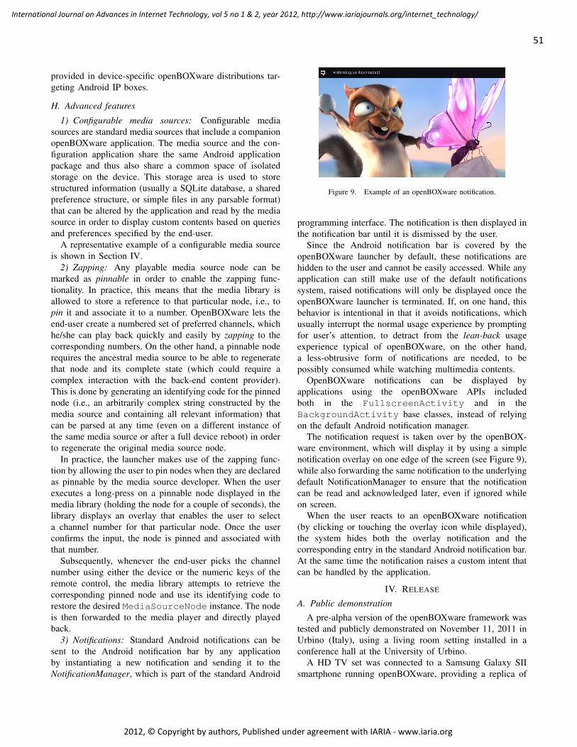
provided in device-specific openBOXware distributions tar-geting Android IP boxes.
H. Advanced features
1) Configurable media sources: Configurable mediasources are standard media sources that include a companionopenBOXware application. The media source and the con-figuration application share the same Android applicationpackage and thus also share a common space of isolatedstorage on the device. This storage area is used to storestructured information (usually a SQLite database, a sharedpreference structure, or simple files in any parsable format)that can be altered by the application and read by the mediasource in order to display custom contents based on queriesand preferences specified by the end-user.
A representative example of a configurable media sourceis shown in Section IV.
2) Zapping: Any playable media source node can bemarked as pinnable in order to enable the zapping func-tionality. In practice, this means that the media library isallowed to store a reference to that particular node, i.e., topin it and associate it to a number. OpenBOXware lets theend-user create a numbered set of preferred channels, whichhe/she can play back quickly and easily by zapping to thecorresponding numbers. On the other hand, a pinnable noderequires the ancestral media source to be able to regeneratethat node and its complete state (which could require acomplex interaction with the back-end content provider).This is done by generating an identifying code for the pinnednode (i.e., an arbitrarily complex string constructed by themedia source and containing all relevant information) thatcan be parsed at any time (even on a different instance ofthe same media source or after a full device reboot) in orderto regenerate the original media source node.
In practice, the launcher makes use of the zapping func-tion by allowing the user to pin nodes when they are declaredas pinnable by the media source developer. When the userexecutes a long-press on a pinnable node displayed in themedia library (holding the node for a couple of seconds), thelibrary displays an overlay that enables the user to selecta channel number for that particular node. Once the userconfirms the input, the node is pinned and associated withthat number.
Subsequently, whenever the end-user picks the channelnumber using either the device or the numeric keys of theremote control, the media library attempts to retrieve thecorresponding pinned node and use its identifying code torestore the desired MediaSourceNode instance. The nodeis then forwarded to the media player and directly playedback.
3) Notifications: Standard Android notifications can besent to the Android notification bar by any applicationby instantiating a new notification and sending it to theNotificationManager, which is part of the standard Android
Figure 9. Example of an openBOXware notification.
programming interface. The notification is then displayed inthe notification bar until it is dismissed by the user.
Since the Android notification bar is covered by theopenBOXware launcher by default, these notifications arehidden to the user and cannot be easily accessed. While anyapplication can still make use of the default notificationssystem, raised notifications will only be displayed once theopenBOXware launcher is terminated. If, on one hand, thisbehavior is intentional in that it avoids notifications, whichusually interrupt the normal usage experience by promptingfor user’s attention, to detract from the lean-back usageexperience typical of openBOXware, on the other hand,a less-obtrusive form of notifications are needed, to bepossibly consumed while watching multimedia contents.
OpenBOXware notifications can be displayed byapplications using the openBOXware APIs includedboth in the FullscreenActivity and in theBackgroundActivity base classes, instead of relyingon the default Android notification manager.
The notification request is taken over by the openBOX-ware environment, which will display it by using a simplenotification overlay on one edge of the screen (see Figure 9),while also forwarding the same notification to the underlyingdefault NotificationManager to ensure that the notificationcan be read and acknowledged later, even if ignored whileon screen.
When the user reacts to an openBOXware notification(by clicking or touching the overlay icon while displayed),the system hides both the overlay notification and thecorresponding entry in the standard Android notification bar.At the same time the notification raises a custom intent thatcan be handled by the application.
IV. RELEASE
A. Public demonstration
A pre-alpha version of the openBOXware framework wastested and publicly demonstrated on November 11, 2011 inUrbino (Italy), using a living room setting installed in aconference hall at the University of Urbino.
A HD TV set was connected to a Samsung Galaxy SIIsmartphone running openBOXware, providing a replica of
51
International Journal on Advances in Internet Technology, vol 5 no 1 & 2, year 2012, http://www.iariajournals.org/internet_technology/
2012, © Copyright by authors, Published under agreement with IARIA - www.iaria.org

Figure 10. The openBOXware test bed, including a TV set driven by anAndroid smartphone controlled by a Bluetooth remote and several otherAndroid devices connected to the same WLAN.
the screen user interface (in its original display resolution)through the HDMI port. The smartphone was placed close tothe TV and far away from the sofa in order to force the end-user to rely on a remote control to issue commands (namely,a Bluetooth Logitech diNovo Mini wireless keyboard that canwork both as a remote and as a wireless keyboard/mouseinput device). The smartphone was connected to the Internetthrough a Wi-Fi router. Other Android devices (smartphones,tablet PCs, and IP boxes) running openBOXware wereconnected to the same WLAN for testing purposes. Oneof the smartphones was also running an UPnP server inthe background. All devices were able to access Internetresources, files shared by the UPnP server, and resourcesstored on a HTTP server installed on a local computerplaying the role of a proxy of video contents from RAIRadiotelevisione Italiana.
A schematic representation of the setting is provided inFigure 10. The setup was used to demonstrate the usabilityof openBOXware in a pure lean-back setting, to test themultimedia playback capabilities of the devices involved,and to show the key features of the platform by means ofrepresentative use cases. A video log of a demo is availableat: http://youtube.com/watch?v=7RzdIiz1EQs.
Demonstrated features include: home screen navigation(see video log at 2:49s), media source exploration of repre-sentative media sources such as a Youtube channel, a UPnPclient, and a HTTP proxy of RAI streaming contents (at4:18s), playback of a full HD video, control bar (at 5:28s,with event injection from both the touch screen and theremote control), sidebar (5:57s), channel shortcut assignmentand zapping (6:55s), multiple launch modes (8:10s) shownon a simple Google News client supporting both full screenand background execution modes, and configurable mediasource samples, such as UPnP and Youtube clients (10:20s).
The experiments conducted on configurable media sourcesare worth to be described in detail. Both the YouTube and theUPnP media sources developed for testing purposes had theirown companion applications to be used to customize them
outside the media library (which in fact provides only aninterface for content consumption). The UPnP configurationapplication (called “My UPnP”) showed the list of allavailable UPnP servers on the current network and allowedthe user to pick a device (or a specific shared folder onthat device) to be made available within the UPnP mediasource. Upon configuration, a node was added to the mediasource tree which directly connected to that folder allowingits contents to be played back by the media player.
Similarly, the Youtube configuration application (called“My YouTube”) allowed the user to generate a set of customchannels, each based on a custom search query. A “snow-boarding” channel (with contents sorted by publication date)was created and used during the demo.
Since both the configurable media sources used for testingpurposes supported pinnable media source nodes, numericshortcuts were added to the custom nodes in order to makethem look as linear channels.
As a final remark, both UPnP and YouTube channels weredynamic in nature, in that the contents they granted accessto changed over time. In particular the UPnP channel, whenselected from the media library, connected to the UPnPserver to obtain the list of resources available at that partic-ular time in the device/folder specified by the configurationapplication. Similarly, the search criteria associated with thecustom YouTube channel were applied whenever the channelwas invoked. In both cases, the multimedia contents wereorganized at runtime in a list of media elements and passedto the media player for continuous playback.
This inherent update capability of the custom channelswas demonstrated during the demo by showing on the TVscreen the most recent snowboarding video on YouTube, andthe slideshow of the pictures taken during the presentationwith a smart phone running a UPnP server service.
B. Beta release
The openBOXware framework has been released onMarch 1st, 2012 and can be installed on any Android de-vice: https://play.google.com/store/apps/details?id=it.uniurb.openboxware.launcher. The Google Play marketplace hasbeen populated with the core environment and some defaultadd-ins (sample media sources and applications) that canbe installed and integrated with the launcher. Stubs ofrepresentative use cases will be also published to providea base for the development of other resources.
The current release is compatible with Android version2.2.1 and superior (compatibility with Android ICS 4.0has not been assessed yet) and it has been tested on avariety of devices, including: Motorola Atrix smartphone,based on nVidia Tegra 2 SoC (Dual ARM Cortex-A9, at1 GHz), with 1 GB RAM, 4.0’ screen (540×960), runningAndroid 2.2; Asus Transformer TF101 tablet/notepad, basedon nVidia Tegra 2 SoC (Dual ARM Cortex-A9 at 1 GHz),with 1 GB RAM, 10.1’ screen (1280×800), running Android
52
International Journal on Advances in Internet Technology, vol 5 no 1 & 2, year 2012, http://www.iariajournals.org/internet_technology/
2012, © Copyright by authors, Published under agreement with IARIA - www.iaria.org

3.2; Samsung Galaxy SII smartphone, based on ExynosSoC (Dual ARM Cortex-A9 at 1.228 GHz), with 1 GBRAM, 4.3’ screen (480×800), running Android 2.3; and anAndroid IP-box (http://www.artwaytech.com/goodpro.php?id=266) based on Samsung PV210 SoC (Cortex A8 CPUat 1 GHz), with 512 MB RAM, 2GB Flash memory, HDMIvideo & Audio output, running Android 2.2.
V. CONCLUSIONS
The advent of digital broadcast television, the diffusionof mobile broadband networks, the computational power ofsmartphones, and the success of open application frame-works have enabled the de facto convergence between mo-bile devices and set-top boxes and between broadcast televi-sion and online multimedia contents. Such a convergence hasbeen exploited so far to create a thriving market of connecteddevices (including the so-called IP-boxes and smart-TVs)and to enhance the usage experience of television viewers(by making available additional IPTV and Internet TVchannels, and by granting Internet browsing capabilities toany television set). Taking a different perspective, however,the same enabling conditions could be exploited to enhanceusability and to reduce device diversity.
This is the starting point of this paper, further supportedby two observations: first, watching television is a muchmore inclusive experience than browsing the Internet; sec-ond, in spite of the proliferation of any sort of connecteddevices, smartphones are the preferred ones with clearcompetitive advantages which prevent them to be outstrippedin the near future.
This paper has introduced openBOXware for Android, anapplication suite that can be easily installed in any Androiddevice (including a smartphone) to make it work as a set-topbox while also maintaining compatibility with all the appli-cations installed in it. The openBOXware core encompassesa launcher, designed to provide a lean-back usage experiencein order to take advantage of the personalized runtimeenvironment of the smartphone while watching televisionin the comfort of a living room, and a SDK that can beexploited to develop media sources and Android applicationscompatible with a TV-like usage mode.
The paper has outlined the key features of openBOXware,discussed the implementation choices, and presented repre-sentative use cases. In particular, it has been shown thatopenBOXware provides the opportunity of creating customTV channels made of linearized contents possibly taken fromheterogeneous sources (including local file systems, UPnPservers, streaming servers, and HTTP servers). Custom chan-nels can be associated with numeric short cuts in order tomake it possible to directly zap into them using a standardremote control. This makes it possible for elders and kidswho are not used to browse the Internet to gain access toonline contents organized in personalized linear TV channelsby their family members.
OpenBOXware will be available on the Android marketsince March 1, 2012.
ACKNOWLEDGMENTS
The research leading to these results has received fund-ing from the EU IST Seventh Framework Programme([FP7/2007-2013]) under grant agreement n 25741, projectULOOP (User-centric Wireless Local Loop), and from theItalian ICT4University Programme, project U4U (Universityfor University). The authors would like to thank RAI Ra-diotelevisione Italiana, BAX srl, and IMAB Group SpA fortaking part in the setup of the demo, as well as BeatriceBucciarelli and Lorenzo Bravi for their contribution to theimplementation of openBOXware.
REFERENCES
[1] L. Klopfenstein, S. Delpriori, G. Luchetti, E. Lattanzi, andA. Bogliolo, “Making an Android Tablet Work as a Set-Top Box,” in Proceedings of the International Conferenceon Andvances in Future Internet, ser. AFIN-2011. IARIA,2011, pp. 64–68.
[2] K. Mikkonen, “Exploring the creation of systemic value forthe customer in advanced multi-play,” TelecommunicationsPolicy, vol. 35, no. 2, pp. 185 – 201, 2011.
[3] L. Zhou, A. V. Vasilakos, L. T. Yang, and N. Xiong,“Multimedia Communications over Next Generation WirelessNetworks,” EURASIP Journal on Wireless Communicationsand Networking, 2010.
[4] Akamai, “Q3 2010 - The State of the Internet,” Akamai report,2011.
[5] Cisco, “Visual Networking Index: Global Mobile Data TrafficForecast Update, 2010-2015,” Cisco White Paper, 2011.
[6] A. Holzer and J. Ondrus, “Mobile Application Market: AMobile Network Operators’ Perspective,” in Exploring theGrand Challenges for Next Generation E-Business, ser. Lec-ture Notes in Business Information Processing, W. Aalst et al.,Eds. Springer Berlin Heidelberg, 2011, vol. 52, pp. 186–191.
[7] C. Maturana, A. Fernndez-Garca, and L. Iribarne, “An im-plementation of a trading service for building open and inter-operable dt component applications,” in Trends in PracticalApplications of Agents and Multiagent Systems, ser. Advancesin Intelligent and Soft Computing, J. Corchado et al., Eds.,2011, vol. 90, pp. 127–135.
[8] A. Schroeder, “Introduction to MeeGo,” IEEE PervasiveComputing, vol. 9, no. 4, pp. 4–7, 2011.
[9] D. Gavalas and D. Economou, “Development platforms formobile applications: Status and trends,” IEEE Software,vol. 28, no. 1, pp. 77–86, 2011.
[10] E. Tsekleves, R. Whitham, K. Kondo, and A. Hill, “Inves-tigating media use and the television user experience in thehome,” Entertainment Computing, 2011.
[11] M. Butler, “Android: Changing the Mobile Landscape,” IEEEPervasive Computing, vol. 10, no. 1, pp. 4–7, 2011.
53
International Journal on Advances in Internet Technology, vol 5 no 1 & 2, year 2012, http://www.iariajournals.org/internet_technology/
2012, © Copyright by authors, Published under agreement with IARIA - www.iaria.org

Enhanced QoS and QoE Support in UMTS Cellular Architectures Based on Application Requirements and Core Network Capabilities
An Autonomic Resource Management Perspective
Emanuel Puschita, Andra Elena Iulia Pastrav, Cristian Androne, Tudor Palade
Communications Department Technical University of Cluj-Napoca
Cluj-Napoca, Romania [email protected],
[email protected], [email protected], [email protected]
Alexandru Caruntu Research & Development Department
Nokia Romania SRL Cluj-Napoca, Romania
Abstract—The goal of this paper is to propose a solution in order to enhance the quality of services support inside the Internet Protocol-based packet switched domain of an Universal Mobile Telecommunications System architecture. The originality of this approach lies in the perspective of an integrated functionality defined at the conjunction of the service requests with the network capabilities. Objective quality of services and quality of experience analysis will highlight the benefits of the autonomic resource management in terms of average end-to-end delay, jitter and mean opinion score.
Keywords-UMTS; QoS support; QoE perception; autonomic management.
I. INTRODUCTION The success of the Internet Protocol (IP) technology, as
evidenced by the variety of many types of applications and network architectures, has proven its centrality through the way it has influenced, and often determined the daily life.
Continuous user demands for traffic capacity determined the operators and infrastructure providers to identify and to offer end-to-end solutions including carefully-managed connections and high-quality user services and experience. In this context, Internet’s ubiquity has revealed a number of shortcomings that the current architecture cannot solve.
Hence a multitude of solutions have been developed to approach problems such as addressing, routing, congestion, resource management or traffic precedence.
In a sustained effort to improve resource management for mobile network environments, our previous work was focused on the benefits offered by an integrated Quality of Services (QoS) support inside the Universal Mobile Telecommunications System (UMTS) IP packet switched (PS) part of the Core Network (CN) domain [1]. Introducing a realistic radio access network modeling, the work presented in this paper completes over the quality of delivered services.
In this way, we demonstrate the need for a correlation between the application request and the network context as
the basic background of an integrated autonomic resource management.
A similar solution that considers the needs for built in quality control functions needed by many applications, addresses the resource management issue by combining a routing procedure and an information model for the representation of connection properties [2].
Two major trends can be distinguished in the way the scientific community understood solving this set of problems, namely: the complete remodeling of the Internet architecture (i.e., 4WARD [3], AUTOI [4], 4D [5], GENI [6]), and the gradual improvement of functionalities in the existing architecture [7] (i.e., Self-NET [8]).
The complete remodeling of the Internet architecture offers a purist approach, a clean slate kind of modeling the new architectural elements. On the other hand, the gradual development of network architecture, ruled by a pluralistic approach, considers that the leap towards a new Internet architecture is impossible independently of the existing technologies.
Promoting the functionality promised by a clean slate approach (flexibility, reliability, fault-tolerance, autonomy and manageability), the authors of this paper believe however that passing to an architecture that will integrate all these features is progressive, at least for two reasons: the perspective of operators and Internet service providers on radical changes in the network and the difficulty in testing, evaluating and validating the proposed new architectural elements.
Beyond the need for new legislative and normative agreements between Internet service providers and network operators, agreements required by fundamental architectural changes. Therefore, a major issue in the revolutionary innovation of the Internet architecture is the difficulty of assessing the new concepts in real experimental scenarios.
In [9], Peterson disputes the promotion of new architectural ideas, calling the scientific community to test the proposed solutions in the experimental “M-Lab” test-bed site [10], a validation site completely different from what means the evaluation by simulation or emulation.
54
International Journal on Advances in Internet Technology, vol 5 no 1 & 2, year 2012, http://www.iariajournals.org/internet_technology/
2012, © Copyright by authors, Published under agreement with IARIA - www.iaria.org
Although the reality of testing on an experimental platform is undeniable, the risk is to focus the proposed solutions on an single extremely narrow issue.
Therefore, the authors of this paper believe that prior to a live testing phase there are several steps that must be completed by simulation and emulation, namely: monitoring and highlighting critical situations to identify network problems, testing the effect of local parametric adjustments on the whole system, development and gradual integration of scalable features in a new architecture. Therefore, stepping towards a revolutionary architecture is a matter of time; the new capabilities added to the existing architectural elements represent the prerequisites for success in this matter. Because of this, we believe that it is impossible to jump towards an architecture, which is independent of the existing technologies, the argument of this statement being found in the evolutionary pluralist concept.
Starting from these premises, which combine the requirements of a clean slate paradigm with current technological reality, the paper aims to investigate and test the benefits of integrating autonomic resource management capabilities into the UMTS CN architectural domain to enhance the QoS support.
In addition to analyzing QoS parameters such as average end-to-end delay, throughput or average jitter experienced by time-critical applications in the UMTS radio access network domain (UMTS RAN) [11], this paper enhances and extends the QoS / Quality of Experience (QoE) support even to the UMTS IP PS domain by integrating an autonomic resource management through network virtualization.
As the native UMTS QoS support is based only on service level classification in the Radio Access Network (RAN) domain, by describing, transmitting and correlating particular requirements of the source application with the context of IP PS domain, an optimal end-to-end performance could be offered through network virtualization in the CN.
In the context of this paper, by a native UMTS QoS support we consider a UMTS system offering QoS traffic differentiation by default. It is worth mentioning that the UMTS traffic classification covers only a certain part of the system and is closer to the physical connection (the RAN part), and therefore always has more stringent requirements in terms of QoS parameters.
Section II of the paper describes the radio access techniques, the architectural elements and the capabilities of the UMTS network domains that support various QoS traffic classes.
A holistic view of the quality of delivered services through the UMTS QoS support is completed by a QoE perspective. The QoE concept, the evaluation models and the parameters involved in the QoS objective analysis are presented in Section III.
Section IV presents the system model calibration for UMTS RAN in terms of Cumulative Distribution Function (CDF) of the Signal-to-Noise Interference level (SINR) for users in one cell that maximize the performances of the UMTS air interface. The UMTS RAN system model parameters that guarantee an optimal dimensioning of the network (transmission power, accepted co-channel
interference levels, radio range and cell capacity) are determined. Then, the performances of QoS/QoE support traffic classes for applications that have stringent requirements concerning the time component are evaluated.
The UMTS RAN dimensioning is performed by using Matlab, while the end-to-end system performance evaluation is performed by using QualNet 5.1 network simulator [12].
In Section V, the premises for an autonomic resource management that ensures a higher quality support in the UMTS CN are investigated in terms of QoS/QoE support.
This fact is accomplished by the ability of the application to select an alternative route between UMTS CN entities, the Serving GPRS Support Node (SGSN) and the Gateway GPRS Support Node (GGSN), based on its knowledge of the source requirements.
Finally, Section IV presents the conclusions of the conducted study by showing the perspective of an autonomic management of network resources that is based on the conjunction of application requirements and network context.
II. AN OVERVIEW OF THE UMTS CELLULAR SYSTEM We will present the radio access techniques, the
architectural elements and capabilities of the UMTS network domains that support various QoS traffic classes.
A. UMTS Radio Access Techniques The Universal Mobile Telecommunications System is
one of the third generation (3G) cellular system technologies. It uses Wideband Code Division Multiple Access (WCDMA), a direct-sequence spread spectrum access technology developed by NTT DoCoMo [13].
NTT DoCoMo submitted WCDMA specification to the International Telecommunication Union (ITU) as a proposal for the air interfaces of the ITU IMT-2000 family of 3G Standards. Therefore WCDMA was selected as an air interface for UMTS system, the 3G successor to Global System for Mobile Communications (GSM).
Since it is GSM down-compatible, some of the UTMS key features include the two basic multiplexing modes, Time Division Duplexing (TDD) and Frequency Division Duplexing (FDD). The advantages offered by the use of WCDMA, a time-frequency space multiplexing technique were reflected in extended network coverage and increased cell capacity. This is a direct consequence of the accepted cell interference vs. number of mobile users in the system compromise. The benefits of using WCDMA over other multiple access techniques also reflect on adaptive power control, variable transmission rates and inherent QoS support.
B. UMTS Network Architecture The UMTS network architecture consists of three
interacting parts: the User Equipment (UE) or Mobile Equipment (ME), the UMTS Terrestrial Radio Access Network (UTRAN) and the Core Network (CN). Due to its various radio access supported methods, the UMTS UE is capable of working in three modes: Circuit Switching (CS), Packet Switching (PS) and hybrid CS/PS mode [14].
55
International Journal on Advances in Internet Technology, vol 5 no 1 & 2, year 2012, http://www.iariajournals.org/internet_technology/
2012, © Copyright by authors, Published under agreement with IARIA - www.iaria.org

The RAN part consists of the Base Stations (BSs) or Node Bs and Radio Network Controllers (RNCs). The main functions of the BS are air interface transmission / reception, signal modulation / demodulation, while major functions of the RNC are power control, admission control, channel allocation, radio resource control / management, data multiplexing / demultiplexing.
The CN part provides data switching, routing and handles the user traffic. It also contains the network user registries or databases and the network management functions. Offering both CS and PS, the CN is divided in two domains: CS domain and PS domain. The CS domain network elements are the Mobile Services Switching Centre (MSC), Visitor Location Register (VLR) and Gateway MSC (GMSC). The PS elements are the SGSN and the GGSN. Network operational and maintenace elements like HLR, VLR, Equipament Identifier (EIR) and Authentificantion Center (AuC) are shared by both domains.
Concluding, we have to note that the UMTS CN part is based on the GSM network architecture with General Packet Radio Service (GPRS) support.
In order to achieve a certain QoS support, UMTS network has defined a so-called “Bearer Service”. A bearer service includes all aspects needed to enable the provision of a contracted QoS, including the control signaling, user plane transport and QoS management functionality.
C. UMTS QoS Support Various types of bearer service were established between
different parts of UMTS network. In addition, each bearer service on a specific layer offers its individual services using services provided by the layers below.
It is worth mentioning that bearers that cover only a certain part of a system and are closer to the physical connection always have more stringent QoS requirements.
In order to solve the QoS problem, UMTS defines four types of traffic classes: Conversational (CO) Class, Streaming (ST) Class, Interactive (IN) Class and Background (BK) Class [15]. The main difference between these QoS classes is the transfer delay value. Conversational QoS Class includes real-time applications that require stringent limits for delay value, while Background QoS Class is the most delay insensitive traffic class.
Table I shows the main characteristics of the above- mentioned QoS classes and examples of corresponding applications.
TABLE I. MAIN CHARACTERISTICS OF UMTS QOS CLASSES
Traffic classes Characteristics Application
Conversational (CO) Class
low delay, low jitter, symmetric traffic, no buffering
speech, voice over IP (VoIP), video, video gaming
Streaming (ST) Class
moderate delay, moderate jitter, asymmetric traffic, buffering allowed
multimedia, video streaming, audio streaming, video on demand
Interactive (IN) Class
moderate jitter, asymmetric traffic, buffering allowed, request response pattern
web browsing, network gaming, databases access
Background (BK) Class
destination doesn’t expect data within a certain time, preserve payload content, asymmetric traffic, buffering allowed
email, file downloading, fax, short message services (SMS)
In order to define the traffic characteristics, the UMTS network architecture introduces a set of QoS attributes. It must be mentioned that a particular type of traffic class is itself a QoS attribute.
There are attributes specific to all classes (i.e., maximum bit rate, delivery order, maximum SDU (Service Data Unit) size) and some attributes that are applied only to a specific class (i.e., transfer delay is applied only to conversational and streaming classes; traffic handling priority is applied only to interactive class).
III. QUALITY OF EXPERIENCE QoE is defined by the ITU-T as “the overall acceptability
of an application or service, as perceived subjectively by the end-user” [16], thus it measures the performance expectations of the user. It is also stated that QoE includes “the complete end-to-end system effects”, meaning that the source quality, the effects of the network, protocols, source codecs, terminals equipments etc. are reflected in the quality perception at the end-user.
Although it may seem that it overlaps with the QoS notion, QoE is not limited to the performances of the network. The end-user perception is also influenced by non-technical aspects such as environmental, sociological, and psychological factors, and thus it would be more accurate to say that QoE augments QoS by linking the performance of the system and the user’s expectations.
As expected, due to the fact that it reflects the user’s opinion regarding the quality of the transmission, QoE cannot be easily evaluated. However, two types of evaluation methods are usually approached: the subjective and the objective one.
In order to evaluate the quality of a transmission from a subjective perspective, different tests and experiments have to be conducted using human subjects. This tests directly ask the participants to rate their experience regarding a certain service. Although this method is the only way of assessing the psychological and sociological impacts on QoE, it is expensive and time consuming [17]. Consequently, the second evaluation method is used in order to implement several models that associate the network performance with the user's level of satisfaction.
As described in [18], in the process of developing such a model, three main steps have to be considered: (1) analyze key QoS parameters that have an impact on the performance perceived by the user (e.g. delay, jitter or packet loss [19]) and identify the relationship between them and QoE, (2) measure the parameters considered in the first step and (3) use mapping metrics to rate the QoE based on the QoS measured parameters.
A. Objective QoE Analysis: The E-model The most popular model used to predict the quality of a
voice application is the E-model [20]. It is an objective
56
International Journal on Advances in Internet Technology, vol 5 no 1 & 2, year 2012, http://www.iariajournals.org/internet_technology/
2012, © Copyright by authors, Published under agreement with IARIA - www.iaria.org

method used to compute the performances of an end-to-end voice transmission and thus anticipate the quality perceived by the end-user taking into account the network impairment parameters like packet loss and delay.
The primary outcome of the E-model is the Rating Factor R as in (1)
AeffeIdIsIRR +−−−−= 0 , (1)
where R0 is the Signal to Noise Ratio, Is represents the impairments that occur at the same time as the voice signal, Id represents the impairments caused by the delay, Ie-eff is the effective equipment impairment factor (caused by the low rate codecs), and A is the advantage factor, which may compensate for some of the impairment factors assuming that there are other advantages of access to the user [21].
By processing the R factor, an estimation of the user's opinion can be obtained.
B. Mean Opinion Score The Mean Opinion Score (MOS) is the most used QoE
metric and is defined in [16] as “the value on a predefined scale that a subject assigns to his opinion of the performance of the telephone transmission system used either for conversation or only for listening to spoken material”.
Although this definition reffers to the telephone transmission system, the MOS is used in the evaluation of voice and video applications too. MOS is expressed as a number between 1 and 5, from the lowest to the highest perceived quality.
Table II presents the correspondence between the absolute value of MOS, the perceived quality descriptor and the degradation of the transmission as perceived by the user.
TABLE II. MOS CORRESPONDENCE TABLE
MOS Quality descriptor Degradation 5 Excellent Imperceptible 4 Good Perceptible 3 Fair Slightly annoying 2 Poor Annoying 1 Bad Very annoying
A correspondence between the value of the R factor and
MOS [20] is given in (2):
.5.4,100
,6107)100)(60(035.01,1000
,1,0
=>
−⋅−−++=<<
=<
MOSR
RRRRMOSR
MOSR
(2)
C. QualNet 5.1 implementation of MOS In addition to describing the subjective opinion, MOS is
also used for scores that originate from objective models, like the one implemented by Scalable Networks for QualNet 5.1 simulator.
QualNet Simulator provides several parameters describing the performances of the network in the simulated scenarios. Among the usual objective parameters, MOS is also computed, based on the ITU-T E-model presented earlier.
The R factor is computed in a simplified manner as in (3)
efIdIR −−= 2.93 , (3)
where Id represents the impairment factor due to the delay in the network expressed by (4)
)3.177()3.177(11.0024.0 −−+= dHdddI . (4)
Parameter d is the one-way delay (including coding,
network and de-jitter delay) and Ief (5) is the impairment caused by the low bit rate
)04.0()701ln(19)04.0()151ln(30 −++−+= eHeeHeefI , (5)
where e is the error probability and H(x) = 0 for x < 0 and H(x) = 1 for x ≥ 0 [12]. The formulae for computing MOS by means of the R factor are presented in (2).
IV. UMTS RAN SYSTEM MODEL AND NATIVE UMTS QOS SUPPORT EVALUATION
In this section, the system model calibration for UMTS RAN in terms of CDF of the SINR level for users in one cell that maximize the performances of the UMTS air interface is determined. Then, the performances of QoS/QoE support traffic classes for applications that have stringent requirements concerning the time component are evaluated.
A. Radio Access System Model Parameter Calibration The air interface calibration scenario considered in this
paper consists of a 1.4 x 1.4km2 area, in which a UMTS RAN has been deployed.
The UMTS RAN calibration system model considers seven Node Bs deployed, each of them having three-sector antennas. The Inter-Site Distance (ISD) is considered to be 500m, as for a typical urban environment. Furthermore, the NodeBs transmit powers are set to 20W.
57
International Journal on Advances in Internet Technology, vol 5 no 1 & 2, year 2012, http://www.iariajournals.org/internet_technology/
2012, © Copyright by authors, Published under agreement with IARIA - www.iaria.org

The radio propagation model considered in the simulations consists of a log-distance path loss model with fixed and exponential coefficients taken from [21].
The amplitude change caused by shadowing is modelled using a log-normal distribution with a standard deviation according to the log-distance model. The shadow fading maps were generated based on the method in [22] with the standard deviation parameters taken from [21]. The summary of the full range of parameters used in the simulations is presented in Table III.
TABLE III. UMTS RAN SIMULATION PARAMETERS
Path loss Path-loss is modelled as 11.81+ 38.63 log10(d) for network users, where d is the distance from the base station in meters.
Shadow fading
Shadow fading is modelled as spatially correlated random process with log-normal distribution (6dB standard deviation), spatial correlation r(x) = ex/20 for distance x.
Receiver noise power
The receiver noise power is modelled as 10 log10 (kT NF W) where the effective noise bandwidth is given as W = 3.84 × 10⁶Hz, and kT = 1.3804 × 10-23 × 290W/Hz. The noise figure at the UE is NF[dB] = 7dB.
Base station
antenna gain
The base station antenna gain is calculated as 2
max
max
( ) min 12 , , with
70 /180 angle where gain pattern is 3dB down from peak 20dB sidelobe gain level in dB
16dB maximum gain level in
s
s
G dB G G
GG
θθ π θ πβ
β π
⎡ ⎤⎛ ⎞= − − ≤ ≤⎢ ⎥⎜ ⎟
⎢ ⎥⎝ ⎠⎣ ⎦==
= dB Radio system simulations were carried out in order to
investigate the performances of the UMTS mobile network. The simulation parameters were taken from Table III, and if not otherwise mentioned they will be the same for all the simulations carried out in the paper.
The received signal strength on the downlink direction is calculated as in (6)
antennaPshadowPlossPtxPRxP +++= , (6)
where txP is the transmit power of the base station; lossP is the path loss component calculated according to Table III;
shadowP is the shadow fading component at the user location defined by the parameters in Table III; antennaP is the antenna gain component specific for the three sector antenna used at the Node B transmitter.
In order to have a general view of the system model, Figure 1 presents the level of the received signal strength throughout the environment. The levels for the received signal are calculated according to equation (6). For a better understanding and clarity of the figure, the values of the signal displayed in Figure 1 are calculated without considering any shadow fading.
The values of the received signal strength are given in dBm, according to the colour bar on the right hand side of the figure. The resolution of the map is 2m.
Figure 1 presents the general view of the system model, but in order to understand the performances of the network we need to analyse it cell-wise. In order to do this, we will further concentrate on one of the three hexagonal cells of the centre base station.
Figure 1. Received signal strength level for the considered environment
The analyzed parameter in this case will be the signal to interference plus noise ratio (SINR), defined as in (7)
)int(max_ noisePerferencePRxPSINR +−= , (7)
where max_RxP is the received signal strength from the best server; erferencePint is the sum of the contributions of all the other base stations; noiseP is the receiver noise power defined according to Table III.
Using (6), the SINR level will be calculated for all the positions in the environment with the same location resolution. Because the level of the noise power at the user location is -101.13dBm, as calculated from the relations in Table III, the receiver sensitivity considered in the scenario needs to be above this threshold.
One factor, which has a great impact upon the obtained SINR value, is the shadow fading. This phenomenon occurs when an obstacle is situated between the transmitter and the receiver, in our case base station and mobile terminal, respectively. In order to better understand the influence of the shadow fading component upon the level of the obtained SINR, we will vary the value of the shadow fading standard deviation. The analysis we conducted led us to the results presented in Figure 3, which illustrates the CDF of the obtained SINR value for all the user positions in one of the hexagonal centre cells.
The results are calculated for the instances when we have no shadow fading, shadow fading with standard deviation 4, 6, 8 and 10, respectively.
58
International Journal on Advances in Internet Technology, vol 5 no 1 & 2, year 2012, http://www.iariajournals.org/internet_technology/
2012, © Copyright by authors, Published under agreement with IARIA - www.iaria.org

The analysis reveals that the shadow fading has a negative impact upon the obtained SINR value, directly proportional to the increase of the standard deviation.
-10 -5 0 5 10 150
0.1
0.2
0.3
0.4
0.5
0.6
0.7
0.8
0.9
1
SINR [dB]
CD
F
No shadow fadingSigma shadow = 4Sigma shadow = 6Sigma shadow = 8Sigma shadow = 10
Figure 2. CDF of SINR for users in one cell
Because in our scenario we consider a minimum threshold value of the SINR of -6.5dB, the worst case that fulfils this condition is that of using a standard deviation of 6. The minimum value of -6.5dB for the SINR, corresponds to a user throughput of 500kbps.
B. Performance Evaluation of UMTS QoS/QoE Support In order to evaluate the QoS support implicitly provided
by a UMTS network, a scenario including a PLMN (Public Land Mobile Network) was simulated using QualNet 5.1 network simulator, a widely used platform in the defense and telecommunication network design and evaluation [12].
Global parameters configured at the physical UMTS RAN level of the simulation are given in Table IV.
TABLE IV. PHY LAYER CONFIGURATION PARAMETERS
Parameter Value Terrain dimensions 1.4 x 1.4 km2
Up-link channel frequency 1.95 GHz Down-link channel frequency 2.15 GHz
Shadowing Mean 6 dB Node B transmission power 20 W
Simulation time 200 s
The system model parameters previously determined guarantee an optimal dimensioning of the network in terms of signal distribution vs. system capacity. It should be noticed that two different radio channels were used in order to access the network resources. The frequency values of these channels were chosen accordingly with European 3G bands for UMTS 2100 recommendations [23].
The UMTS RAN network scenario includes eight UE nodes: four source nodes (UE nodes 6, 8, 10, and 12) and four destination nodes (UE nodes 7, 9, 11, and 13), as presented in Figure 3.
68
1012
11
9
7
13
CBR CBRCBRCBR
Source Node
Destination Node
NodeB Radio Network Controller
Home Location Register
Serving GPRS Support Node
Gateway GPRS Support Node
Radio Link
Figure 3. UMTS evaluation scenario
Between the source nodes (SN) and destination nodes (DN), four CBR (Constant Bit Rate) applications, each of them corresponding to one QoS class defined by the UMTS network, were considered. The characteristics of all applications are summarized in Table V.
TABLE V. CORRESPONDING QOS CLASS FOR EACH CBR APPLICATION USED IN THE EVALUATION SCENARIO
Application Type SN DN
Items to
Send
Item Size
(bytes)
Interval (s)
QoS Class
CBR
6 7
1000 40 0.1
BK 8 9 IN 10 11 ST 12 13 CO
The results of the simulations concerning the average
end-to-end delay, the average jitter and average MOS for each QoS supported class are presented in Figure 4, Figure 5 and Figure 6 respectively.
Figure 4. Average end-to-end delay experienced by the test applications in each QoS support class
In analyzing the obtained results, it can be noticed that application, which corresponds to the Conversational and
59
International Journal on Advances in Internet Technology, vol 5 no 1 & 2, year 2012, http://www.iariajournals.org/internet_technology/
2012, © Copyright by authors, Published under agreement with IARIA - www.iaria.org

Streaming QoS class, is characterized by the lowest value of average end-to-end delay and jitter delay, as expected for the type of application corresponding to this class (speech, VoIP, video or audio streaming).
Figure 5. Average jitter experienced by the test applications in each QoS
support class
Summarizing, the network complies with the priority level imposed on the test applications that were modeled by CBR-type traffic sources, and this is reflected in the average values of the end-to-end transmission delays and in the jitter for each QoS priority class.
Correlating end-to-end transmission delays with the transmission flow rate and with the time interval between transmitted packets one can notice the increased flow rate in the case of Background class, which is due to transmitting a reduced total number of packets in a very short transmission time interval.
If MOS values are compared, it can be seen that the application from Conversational QoS class has the highest value of this parameter, which corresponds to the lowest value for the average end-to-end delay and the average jitter.
Figure 6. Average MOS experienced by the test applications in each QoS support class
Note that the QualNet simulator offers the possibility to mark the traffic flows by setting the appropriate IP
Precedence field. In this way, the applications are identified, classified and scheduled in the corresponding queues.
V. PERSPECTIVES TOWARDS AN AUTONOMIC RESOURCE MANAGEMENT IN A UMTS NETWORK
Developed within the 3rd Generation Partnership Project (3GPP), the 3G standard suggests an end-to-end QoS support based on a policy management system (Policy-Based Network Management) [15].
The network architecture presented by the first 3GPP public versions has evolved to an architectural model System Architecture Evolution (SAE) [24], which ensures the convergence of different access network categories such as UMTS, 3GPP, Wireless Local Area Network (WLAN) or any other non-3GPP radio access technology.
The latest public 3GPP version considers the IP Multimedia Subsystem (IMS) [23] network architecture to be completely separated from the access technology, having the specific access functions isolated from the core network. By eliminating the hierarchical dependence between the Serving RNC (SRNC) and the corresponding SGSN, a more efficient resource allocation was offered.
In order to manage QoS resources, the SAE architecture integrates an informational QoS Information Function (QIF) function that interacts with all individual network models included within the IMS platform. This QoS resource management solution is an external part of the network, based on the use and interaction between a central entity and periferic elements.
Although in the clean slate approach the resource management and the QoS support are considered an integrated part of communications networks, this fact is not reflected in the characteristics of current systems or by the UMTS network architecture.
Therefore, the perspective of an autonomic resource management in a UMTS network proposed in this paper suggests the necessity of adding additional information at the level of the central UMTS network elements using virtualization technique.
Network virtualization represents a high level abstraction process that overlaps the implementation and physical network configuration details. Allowing co-existence of multiple virtual architectures overlaid on a common substrate physically shared, network virtualization promises flexibility and security, promoting diversity and increased management capacity [24].
In this way, UMTS core network nodes act autonomously, being able to sense the environment, to perceive the changes, to understand internal changes and to react in an intelligent manner by selecting the optimal path according to application requirements.
To demonstrate this, native UMTS QoS support is analyzed in comparison to the potential of the autonomic management offered through network virtualization, using QualNet network simulator [12]. Thus, in the case of an autonomic management system, the proposed analysis scenarios highlight the ability of selecting the best route according to the source application constraints in terms of maximum acceptable end-to-end delay.
60
International Journal on Advances in Internet Technology, vol 5 no 1 & 2, year 2012, http://www.iariajournals.org/internet_technology/
2012, © Copyright by authors, Published under agreement with IARIA - www.iaria.org

A. Scenario description According to [13], it is possible for an UMTS network to
have multiple SGSNs and GGSNs entities, which can be co-located or can be interconnected via an IP subnetwork in order to increase the geographical area served by an operator.
Considering the second approach, an evaluation scenario was developed, in which the SGSN and the GGSN are interconnected via a simple IP sub-network that consists of seven generic routers denoted R1 to R7, as depicted in Figure 7.
Figure 7. The architecture of the evaluation scenario
Obviously, a real-life UMTS IP sub-network would be more complex, the motivation for this topology was to better illustrate the problems that may arise and the proposed solution.
In this evaluation scenario a CBR test application corresponding to Conversational QoS class (highest priority QoS class) was considered. The main parameters that describe the characteristics for the tested application are indicated in Table VI.
TABLE VI. CHARCTERISTICS OF THE MODELED APPLICATION
Application
Type SN DN
Items to
Send
Item Size
[bytes]
Interval [s]
QoS Class
CBR 6 7 1000 40 0.1 CO
As we have already mentioned, the motivation behind this evaluation is to highlight the benefits of the autonomic management offered through a network virtualization process.
In our case, the virtualization process could be illustrated by controlling, through the configuration files, the parametric values that characterize network architectural elements.
Knowing the values of these parameters, it is possible to indicate a dedicated virtual network that offers the best path from source to destination in terms of minimum average end-to-end delay, maximum throughput, packet loss rate on selected route or other stringent requirements specific to a certain type of application.
B. Performance Evaluation In order to emphasize the path selection mechanism
between SGSN and GGSN, core nodes of UMTS IP sub-network, two different cases were evaluated: a native UMTS QoS support selection compared to QoS network support provided by an autonomic network management selection, as a result of dedicated virtual network generation.
When it defines the links between two intermediate generic routers in the UMTS IP sub-network, the simulator allows the association of specific transmission throughput and delay on each link, as presented in Figure 8.
R4
R6
R5
R3
R2
Default Route Selected Route With Respect To Application Requirements
10Gbps10ms
1Gbps20ms
10Mbps2ms
100Mbps2ms
100Mbps2ms
100Mbps5ms
10Gbps2.5ms
100Mbps5ms
1Gbps30ms
R1 R71Gbps10ms
100Mbps1ms
Figure 8. UMTS IP sub-network path selection
Sending the test application scheduled in Conversational Class by the native UMTS QoS support in the RAN domain, the path from router R1 to router R7 in the IP PS sub-network was selected via routers R3, R6 and R4, as illustrated in Figure 7. The path selection was based only on the use of OSPFv2 routing protocol. However, independently of the used routing protocol (e.g., Bellman Ford or RIP), simulation results indicates that there is no correlation between the application requirements and the network selected path. Therefore, the determined path remains the same in case of using default QoS support.
An autonomic network management QoS support should consider and accommodate both differentiated application requirements and dynamic network context. This mandatory integrated capability of the Future Internet (FI) network elements is implemented by means of network virtualization.
The objective of network virtualization process is to generate virtual networks and make each of these virtual networks appear to the user as a dedicated network infrastructure, with dedicated resources and services available for application requests. Therefore, the network virtualization process invokes a mode of selecting the virtual network that best integrates and satisfies the application requests at the physical network level.
It must be mentioned that for the generated virtual network, in our case, only the values of average end-to-end delay and jitter (as a consecutive delay difference) are considered as critical parameters for the source application.
61
International Journal on Advances in Internet Technology, vol 5 no 1 & 2, year 2012, http://www.iariajournals.org/internet_technology/
2012, © Copyright by authors, Published under agreement with IARIA - www.iaria.org

Results of the simulations validate a virtual path from the router R1 to router R7 via routers R4, R3, and R5, a corresponding physical network infrastructure that offers best performances in terms of requested average end-to end delay and jitter.
Parametric results of the average end-to-end delay, the average jitter, and the average MOS, both for native UMTS QoS support and autonomic resource management QoS support in the IP PS domain, are summarized in Table VII.
TABLE VII. PARAMETRIC EVALUATION OF QOS/QOE SUPPORT
Selected path between ingress-egress
nodes in UMTS PS domain
Average end-to-end
delay (s)
Average jitter
(s)
Average MOS
(score) Native QoS support in the
UMTS radio access network R1 → R3 →
→ R6 → R4 → R7 0.109 0.022 3.186
Autonomic resource management based on network virtualization in UMTS IP PS domain
R1 → R4 → → R3 → R5 → R7 0.045 0.022 3.264
As illustrated in Figure 9 and Figure 10, the UMTS IP PS
domain decisively influences the applications performances in terms of average end-to-end delay, jitter and MOS.
Figure 9. Comparative results of the average end-to-end delay and average jitter based on different path selection between ingress-egress
nodes in the UMTS IP PS domain
Figure 10. Comparative results of the aveage MOS based on different path selection between ingress-egress nodes in the UMTS IP PS domain
If the application requests are expressed in terms of a maximum accepted delay [26], the results illustrated in Figure 11 show that the autonomic resource management could satisfy these requests by offering an optimal path inside the UMTS IP PS domain.
Figure 11. Delay variation over the simulation time based on different path
selection between ingress-egress nodes in the UMTS IP PS domain
The QoE objective analysis based on MOS evaluation presented in Figure 12 shows that the user perception of the quality of the delivered service is enhanced by the use of an autonomic resource management support in the UMTS IP PS domain.
Figure 12. MOS variation over the simulation time based on different path
selection between ingress-egress nodes in the UMTS IP PS domain
Therefore, simulation results support the perspective towards an autonomic resource management QoS support that makes the conjunction between the application's requests and the network context by choosing an alternate route in a virtualized environment.
The potential of the autonomic resource management is reflected by the capacity to identify an optimal path between the source node and the destination node, according to the imposed QoS constraints (for example, maximum accepted delay, minimum accepted packet loss, maximum accepted jitter or minimum requested throughput).
62
International Journal on Advances in Internet Technology, vol 5 no 1 & 2, year 2012, http://www.iariajournals.org/internet_technology/
2012, © Copyright by authors, Published under agreement with IARIA - www.iaria.org
Some critical conditions or cost constrains could limit the resource optimization while using the native QoS support on the UMTS radio access network.
These situations request the adaptation of the source application parameters to the network available resources in order to still broadcast the information on the channel.
An implemented and tested solution (i.e., virtualization algorithm, virtualized parameters, in-network message flow, and source adaptation) for the network virtualization concept is offered in [27]. The conjunction between the source application requests and the network context is achieved through the QoS profiles message exchange and it represents the process of network virtualization.
As in [27], the paper assumes the network overflow by probing each UMTS IP PS network link. Nevertheless, the potential of the autonomic resource management is reflected by lower average end-to-end delay and lower jitter.
In order to impose the selected network elements on the virtual path, we used the Multiprotocol Label Switching (MPLS). As the proposed QoS support uses MPLS for route maintenance, it can be applied only in the UMTS IP PS network domain. Therefore, it cannot offer an end-to-end QoS support because RAN domain of the UMTS network does not have implemented the IP protocol.
VI. CONCLUSIONS AND FUTURE WORK Considering a realistic UMTS RAN domain modeling,
the paper aims to investigate the potential benefits that could reside from the integration of the autonomic resource management based on the virtualization process in current UMTS IP PS network domain architecture.
Based on an objective QoS/QoE performance analysis, the upper limit of native UMTS QoS support was analyzed, in a first stage, in terms of average end-to-end delay, average jitter and average MOS. The ability of the UMTS traffic classes to offer quality support for constant bit rate time critical applications was compared with the QoS support resulted from the usage of autonomic resource management.
The obtained results suggest that, since it is closer to the application needs and considering the network context, such an autonomic resource management could improve the native UMTS QoS support. Thus, the enhanced QoS/QoE support would overcome the situations in which the existent QoS mechanism would not even accept the service itself.
As a part of the further work, the authors intend to extend this solution also for the radio access part of the cellular networks. Moreover, future investigation will validate the simulation results through emulation on an experimental test-bet. This investigation will use the EXata emulation server (running the QualNet scenarios) and two operational hosts corresponding to the source and to the destination nodes (transmitting real-time traffic). In this way, a realistic experience of handling live traffic flows will be offered.
ACKNOWLEDGMENTS This paper was supported by the following projects:
"Development and support of multidisciplinary postdoctoral programmes in major technical areas of national strategy of Research - Development - Innovation" 4D-POSTDOC,
contract no. POSDRU/89/1.5/S/52603, project co-funded by the European Social Fund through Sectorial Operational Programme Human Resources Development 2007-2013 and “Doctoral studies in engineering sciences for developing the knowledge based society-SIDOC” contract no. POSDRU/88/1.5/S/60078, project co-funded from European Social Fund through Sectorial Operational Program Human Resources 2007-2013. The logistics costs of the work (research infrastructure, conference fee and accommodation costs) were supported by CNCSIS-UEFISCSU, project number 184/2010.
REFERENCES [1] E. Puschita, G. Manuliac, T. Palade, and A. Caruntu, “QoS
Support in UMTS Networks: Performance Evaluation and Perspectives towards an Autonomic Resource Management”, The Third International Conference on Advances in Future Internet (AFIN 2011), ISBN: 978-1-61208-148-9, 2011, pp. 25-30.
[2] M. Yampolskiy, W. Hommel, V. A. Danciu, M. G. Metzker, and M. K. Hamm, “Management-aware Inter-Domain Routing for End-to-End Quality of Service”, International Journal on Advances in Internet Technology, vol 4, no. 1 & 2, ISSN: 1942-2652, pp. 60-78, 2011. http://www.iariajournals.org/internet_technology/index.html
[3] C. Mingardi, G. Nunzi, D. Dudkowski, and M. Brunner, “Event Handling in Clean-Slate Future Internet Management,” 11th IFIP/IEEE International Symposium on Integrated Network Management (IM 2009), June 2009, pp. 275-278.
[4] L. Mamatas, S. Clayman, M. Charalambides, A. Galis, and G. Pavlou “Towards an Information Management Overlay for Emerging Networks,” 12th IEEE/IFIP Network Operations and Management Symposium (NOMS 2010), April 2010, pp. 527-534.
[5] A. Greenberg, et al., “A clean slate 4D approach to network control and management,” ACM SIGCOMM Computer Communication Review, vol. 35, no. 5, October 2005, pp. 41-54.
[6] D.H.C. Du, “Clean Slate Design of Internet for Supporting Service-Oriented Computing and Applications,” IEEE International Conference on Service-Oriented Computing and Applications (SOCA 07), June 2007, pp. 3-8.
[7] C. Dovrolis, “What would Darwin think about clean-slate architectures?,” ACM SIGCOMM Computer Communication Review, vol. 38, no. 1, January 2008, pp. 29-34.
[8] A. Kousaridas, et al., “Future Internet Elements: Cognition and Self-Management Design Issues”, In ICST (The Institute for Computer Sciences, Social-Informatics and Telecommunications Engineering) (ed.), Proceedings of the SAC-FIRE Workshop, Autonomics 2008 (sponsored by the European Commission), Turin, Italy, September 23-25, 2008.
[9] T. Anderson, L. Peterson, S. Shenker, and J. Turner, “Overcoming the Internet Impasse through Virtualization”, Computer Journal, vol. 38, no. 4, 2005, pp. 34–41.
[10] PlanetLab platform, http://www.planet-lab.org/, March 2011. [11] D. Kaur, P. Rakheja, and A. Kaur, “Analysing Quality of
Service in UMTS”, International Journal of Computer Applications, vol. 11, no. 12, 2010 , pp. 31-34.
[12] QualNet Developer 5.1 Network Simulator, http://www.scalable-networks.com/, March 2011.
[13] C. Kappler, UMTS network and beyond, John Wiley & Sons, West Sussex, 2009.
63
International Journal on Advances in Internet Technology, vol 5 no 1 & 2, year 2012, http://www.iariajournals.org/internet_technology/
2012, © Copyright by authors, Published under agreement with IARIA - www.iaria.org

[14] 3GPP TS 23.101, “General Universal Mobile Telecommunications System (UMTS) architecture”, Release 10, 2010.
[15] 3GPP TS 23.207, “Technical Specification Group Services and System Aspects; End-to-end Quality of Service (QoS) concept and architecture, Release 9, December 2009.
[16] ITU-T Reccomendation P.10/G.100, “Vocabulary for performance and quality of service”, 2006.
[17] R. Stankiewicz, P. Cholda, and A. Jajszczyk, “QoX: What is it really?”, IEEE Communications Magazine, vol. 49, no. 4, April 2011, pp. 148-158.
[18] D. Soldani, M. Li, and R. Cuny, (editors), “QoS and QoE Management in UMTS Cellular Systems”, John Wiley & Sons, 2006.
[19] ITU-T Reccomendation G.1010, “End-user multimedia QoS categories”, 2001.
[20] ITU-T Reccomendation G.107, “The E-model, a computational model for use in transmission planning”, 2005.
[21] 3GPP TR 36.814, “Evolved Universal Terestrial Radio Access (E-UTRA); Further advancements for E-UTRA physical layer aspects”, Release 9, 2010.
[22] H. Claussen, “Efficient modelling of channel maps with correlated shadow fading in mobile radio systems”, in Proc. IEEE International Symposium on Personal, Indoor and Mobile Radio Communications (PIMRC), 2005.
[23] 3GPP TS 23.228, “IP Multimedia Subsystem (IMS); Stage 2”, Release 10, September 2010.
[24] 3GPP TR 23.882, “3GPP system architecture evolution (SAE): Report on technical options and conclusions”, Release 8, September 2008.
[25] A. G. Prieto, et al., “Decentralized In-Network Management for the Future Internet”, IEEE International Conference on Communications (ICC’09), 2009, pp. 1-5.
[26] N. Jingjing Zhang Ansari, “On assuring end-to-end QoE in next generation networks: challenges and a possible solution”, IEEE Communications Magazin, vol. 49, no. 7, 2011.
[27] E. Puschita, T. Palade, A. Moldovan, R. Colda, and I. Vermesan, “An Innovative QoS Paradigm based on Cognitive In-Network Management of Resources for a Future Unified Network Architecture: I-NAME QoS Model”, The Second International Conference on Advances in Future Internet (AFIN 2010), ISBN 978-0-7695-4091-7, 2010, pp. 37-43.
64
International Journal on Advances in Internet Technology, vol 5 no 1 & 2, year 2012, http://www.iariajournals.org/internet_technology/
2012, © Copyright by authors, Published under agreement with IARIA - www.iaria.org

www.iariajournals.org
International Journal On Advances in Intelligent Systems
ICAS, ACHI, ICCGI, UBICOMM, ADVCOMP, CENTRIC, GEOProcessing, SEMAPRO, BIOSYSCOM,BIOINFO, BIOTECHNO, FUTURE COMPUTING, SERVICE COMPUTATION, COGNITIVE, ADAPTIVE,CONTENT, PATTERNS, CLOUD COMPUTING, COMPUTATION TOOLS, ENERGY, COLLA, IMMM, INTELLI,SMART, DATA ANALYTICS
issn: 1942-2679
International Journal On Advances in Internet Technology
ICDS, ICIW, CTRQ, UBICOMM, ICSNC, AFIN, INTERNET, AP2PS, EMERGING, MOBILITY, WEB
issn: 1942-2652
International Journal On Advances in Life Sciences
eTELEMED, eKNOW, eL&mL, BIODIV, BIOENVIRONMENT, BIOGREEN, BIOSYSCOM, BIOINFO,BIOTECHNO, SOTICS, GLOBAL HEALTH
issn: 1942-2660
International Journal On Advances in Networks and Services
ICN, ICNS, ICIW, ICWMC, SENSORCOMM, MESH, CENTRIC, MMEDIA, SERVICE COMPUTATION,VEHICULAR, INNOV
issn: 1942-2644
International Journal On Advances in Security
ICQNM, SECURWARE, MESH, DEPEND, INTERNET, CYBERLAWS
issn: 1942-2636
International Journal On Advances in Software
ICSEA, ICCGI, ADVCOMP, GEOProcessing, DBKDA, INTENSIVE, VALID, SIMUL, FUTURECOMPUTING, SERVICE COMPUTATION, COGNITIVE, ADAPTIVE, CONTENT, PATTERNS, CLOUDCOMPUTING, COMPUTATION TOOLS, IMMM, MOBILITY, VEHICULAR, DATA ANALYTICS
issn: 1942-2628
International Journal On Advances in Systems and Measurements
ICQNM, ICONS, ICIMP, SENSORCOMM, CENICS, VALID, SIMUL, INFOCOMP
issn: 1942-261x
International Journal On Advances in Telecommunications
AICT, ICDT, ICWMC, ICSNC, CTRQ, SPACOMM, MMEDIA, COCORA, PESARO, INNOV
issn: 1942-2601