the idc engineers pocket guide - engineering course · notes the idc engineers pocket guide other...
TRANSCRIPT
The IDC Engineers
Pocket Guide
Fifth Edition - Electrical
Power Systems Protection Power Quality and
Substation Automation
The IDC Engineers Pocket Guide
Published by IDC Technologies 1031 Wellington Street WEST PERTH 6005 AUSTRALIA
Copyright 1994, 1995, 1996, 1997, 1998, 1999, 2000, 2003
IDC Technologies
A.B.N. 78 003 263 189
ISBN 1 875955 09 7
US English. 5th Edition.
All rights to this publication are reserved. No part of this publication may be
copied, reproduced, transmitted or stored in any form or by any means
(including electronic, mechanical, photocopying, recording or otherwise)
without prior written permission from IDC Technologies Pty Ltd.
Trademarks
All terms noted in this publication that are believed to be registered trademarks
or trademarks are listed below:
• PC-DOS,IBM,IBMPC/XT,IBMPC/ATandIBMPS/2areregistered
trademarksofInternationalBusinessMachinesCorporation.
• Microsoft, MS-DOS and Windows are registered trademarks of
MicrosoftCorporation.
• IntelisaregisteredtrademarkoftheIntelCorporation
Disclaimer
Whilst all reasonable care has been taken to ensure that the description, opinions,
listings and diagrams are accurate and workable, IDC Technologies does not
accept any legal responsibility or liability to any person, organization or other
entity for any direct loss, consequential loss or damage, however caused, that
may be suffered as a result of the use of this publication.
Power Systems Protection, Power Quality, Substation Automation
ForewordIDCTechnologiesspecializes inprovidinghighqualitystate-of-the-art technical
training workshops to engineers, scientists and technicians throughout the world.
More than 300,000 engineers have attended IDC's workshops over the past 16
years. The tremendous success of the technical training workshops is based in part
on the enormous investment IDC puts into constant review and updating of the
workshops, an unwavering commitment to the highest quality standards and most
importantly-enthusiastic,experiencedIDCengineerswhopresenttheworkshops
andkeepup-to-datewithconsultancywork.
Concepts that are important and useful to the engineer, scientist and technician,
independent of discipline, are covered in this useful booklet.
Although IDC Technologies was founded in Western Australia in 1986, it now
draws engineers from all countries. IDC Technologies currently has offices in
Australia,Canada,Ireland,Malaysia,NewZealand,Singapore,SouthAfrica,UK
and USA.
We have produced this booklet so that you will get an in-depth, practical coverage
of Communications, LANs and TCP/IP topics. Information at an advanced level
can be gained from attendance at one of IDC Technologies Practical Training
Workshops. Held across the globe, these workshops will sharpen your skills in
today's competitive engineering environment.
The IDC Engineers Pocket Guide
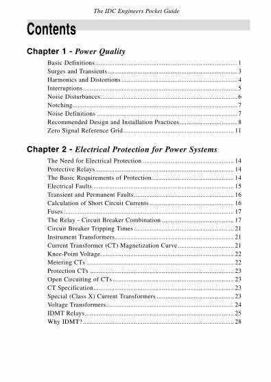
ContentsChapter 1 - Power Quality
Basic Definitions ................................................................................. 1Surges and Transients .......................................................................... 3Harmonics and Distortions .................................................................. 4Interruptions ........................................................................................ 5Noise Disturbances .............................................................................. 6Notching.............................................................................................. 7Noise Definitions ................................................................................ 7Recommended Design and Installation Practices ................................. 8ZeroSignalReferenceGrid ............................................................... 11
Chapter 2 - Electrical Protection for Power SystemsThe Need for Electrical Protection .................................................... 14Protective Relays ............................................................................... 14The Basic Requirements of Protection ............................................... 14Electrical Faults ................................................................................ 15Transient and Permanent Faults ......................................................... 16Calculation of Short Circuit Currents ................................................ 16Fuses ................................................................................................. 17TheRelay-CircuitBreakerCombination ......................................... 17Circuit Breaker Tripping Times ......................................................... 21Instrument Transformers.................................................................... 21CurrentTransformer(CT)MagnetizationCurve ................................ 21Knee-PointVoltage ............................................................................ 22MeteringCTs .................................................................................... 22Protection CTs .................................................................................. 23OpenCircuitingofCTs ..................................................................... 23CT Specification ................................................................................ 23Special(ClassX)CurrentTransformers ............................................ 23VoltageTransformers......................................................................... 24IDMTRelays ..................................................................................... 25WhyIDMT? ...................................................................................... 28
Power Systems Protection, Power Quality, Substation Automation
Chapter 3 - Substation AutomationDefinition of the Term ....................................................................... 30What is Substation Automation ......................................................... 31Electrical Protection .......................................................................... 32Control .............................................................................................. 32Measurement ..................................................................................... 33Monitoring ........................................................................................ 33Data Communication ......................................................................... 34Substation Automation Architecture .................................................. 34ThreeMainDivisions ........................................................................ 35Communications in Substation Automation ....................................... 37
Appendices AppendixA:GlossaryofTerms ........................................................ 39AppendixB:UnitsandAbbreviations ............................................... 71AppendixC:CommonlyUsedFormulae ........................................... 74AppendixD:ResistorColorCoding .................................................. 82
Who is IDC Technologies Benefits of Technical Training ........................................................... 84IDC Technologies Approach to Training ............................................ 84Technical Training Workshops ........................................................... 85On-siteWorkshops ............................................................................ 88Customized Training ......................................................................... 89Locations of Past Workshops ............................................................. 90IDCTechnologiesWorldwideOffices ................................................ 92
NotesThe IDC Engineers Pocket Guide
Other books in this series
INSTRUMENTATION AutomationusingPLCs,SCADAandTelemetry, Process Control and Data Acquisition
COMMUNICATIONS DataCommunications,IndustrialNetworking,
TCP/IPandFiberOptics
ELECTRONICS PersonalComputers,DigitalSignalProcessing andAnalog/DigitalConversions
FORMULAE& Electrical&ElectronicsEngineering, CONVERSIONS MechanicalEngineering,Thermodynamics, FluidMechanics,GeneralMathematics
INDUSTRIAL ProcessControl,InstrumentsandValves, AUTOMATION IndustrialDataComms,HAZOPS, Safety Instrumentation, Hazardous Areas, SCADA and PLCs
Chapter 1 Power Quality
This chapter is broken down into:
• BasicDefinitions
• RecommendedDesignandInstallationPractices
• ZeroSignalReferenceGrid
Basic Definitions
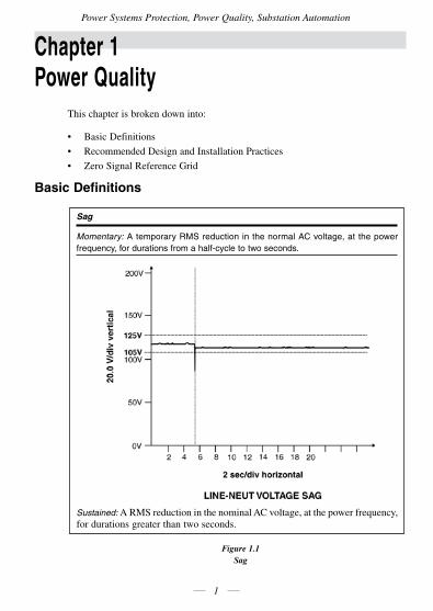
Figure 1.1 Sag
Power Systems Protection, Power Quality, Substation Automation
1
Sag
Momentary: A temporary RMS reduction in the normal AC voltage, at the power frequency, for durations from a half-cycle to two seconds.
Sustained: ARMSreductioninthenominalACvoltage,atthepowerfrequency,for durations greater than two seconds.
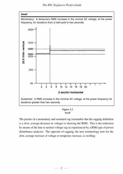
Figure 1.2 Swell
The picture of a momentary and sustained sag (remember that the sagging definition
isaslow,averagedecreaseinvoltage)isshowingtheRMS.Thisisthereduction
bymeansofthelinetoneutralvoltagesagasexperiencedbyaBMItypeofpower
disturbance analyzer. The opposite of sagging, the new terminology now for the
slow, average increase of voltage or temporary increase, is swelling.
The IDC Engineers Pocket Guide
2
Swell
Momentary: A temporary RMS increase in the normal AC voltage, at the power frequency, for durations from a half-cycle to two seconds.
Sustained: A RMS increase in the nominal AC voltage, at the power frequency for durations greater than two seconds.
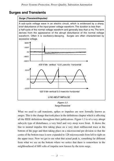
Surges and Transients
Figure 1.3 Surge/Transient
What we used to call transients, spikes or impulses are now formally known as
surges. This is the change that took place in the definitions chapter which is affecting
all the IEEE definitions throughout their publications. Figure 1.3 is of a very abrupt
subcycle type of disturbance, a very brief and very steep wave front. It shows the
line to neutral impulse first taking place on a very short millisecond trace at the
bottom of the page and then taking place on a microsecond per division so that the
centreofthebottomtraceisnowexpandedto128microsecondsfromlefttorighton
the upper trace. Now we get to see what that actual peak is, something far different
from what we see on the bottom where we notice that there is somewhere in the
neighbourhood of 600 volts of impulse now known by the term surge.
Power Systems Protection, Power Quality, Substation Automation
3
Surge (Transient/Impulse)
A sub-cycle voltage wave in an electric circuit, which is evidenced by a sharp, brief disturbance of the input-power voltage waveform. The duration is less than a half-cycle of the normal voltage waveform and generally less than a ms. The term derives from the appearance of the abrupt disturbance of the normal voltage waveform. Often it is oscillatory-decaying. Surges are often characterized by excessive voltage.
The IDC Engineers Pocket Guide
4
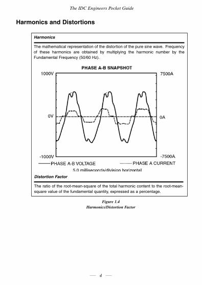
Harmonics and Distortions
Figure 1.4 Harmonics/Distortion Factor
Harmonics
The mathematical representation of the distortion of the pure sine wave. Frequency of these harmonics are obtained by multiplying the harmonic number by the Fundamental Frequency (50/60 Hz).
Distortion Factor
The ratio of the root-mean-square of the total harmonic content to the root-mean-square value of the fundamental quantity, expressed as a percentage.
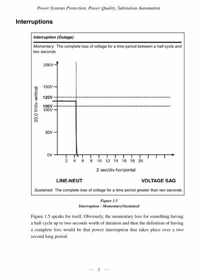
Interruptions
Figure 1.5 Interruption - Momentary/Sustained
Figure1.5speaksforitself.Obviously,themomentarylossforsomethinghaving
a half cycle up to two seconds worth of duration and then the definition of having
a complete loss would be that power interruption that takes place over a two
second long period.
Power Systems Protection, Power Quality, Substation Automation
5
Interruption (Outage)
Momentary: The complete loss of voltage for a time period between a half-cycle and two seconds.
Sustained: The complete loss of voltage for a time period greater than two seconds.
The IDC Engineers Pocket Guide
6
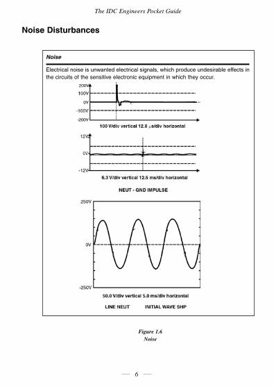
Noise Disturbances
Figure 1.6 Noise
Noise
Electrical noise is unwanted electrical signals, which produce undesirable effects in the circuits of the sensitive electronic equipment in which they occur.
Power Systems Protection, Power Quality, Substation Automation
7
Electrical noise is shown in a variety of ways by the graphs in Figure 1.6. The
undesirable effect on the circuits that serve sensitive electronic equipment are
shown here. These are neutral to ground impulses, as they used to be called; but
which we now call a transient surge.
Notching
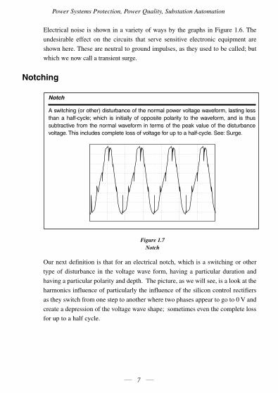
Figure 1.7Notch
Ournextdefinitionisthatforanelectricalnotch,whichisaswitchingorother
type of disturbance in the voltage wave form, having a particular duration and
having a particular polarity and depth. The picture, as we will see, is a look at the
harmonics influence of particularly the influence of the silicon control rectifiers
astheyswitchfromonesteptoanotherwheretwophasesappeartogoto0Vand
create a depression of the voltage wave shape; sometimes even the complete loss
for up to a half cycle.
Notch
A switching (or other) disturbance of the normal power voltage waveform, lasting less than a half-cycle; which is initially of opposite polarity to the waveform, and is thus subtractive from the normal waveform in terms of the peak value of the disturbance voltage. This includes complete loss of voltage for up to a half-cycle. See: Surge.
The IDC Engineers Pocket Guide
8
Noise Definitions
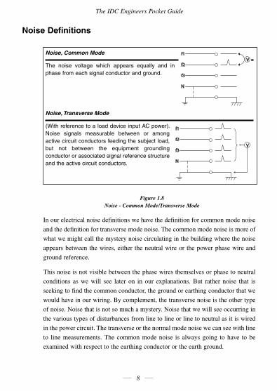
Figure 1.8 Noise - Common Mode/Transverse Mode
In our electrical noise definitions we have the definition for common mode noise
and the definition for transverse mode noise. The common mode noise is more of
what we might call the mystery noise circulating in the building where the noise
appears between the wires, either the neutral wire or the power phase wire and
ground reference.
This noise is not visible between the phase wires themselves or phase to neutral
conditions as we will see later on in our explanations. But rather noise that is
seeking to find the common conductor, the ground or earthing conductor that we
would have in our wiring. By complement, the transverse noise is the other type
of noise. Noise that is not so much a mystery. Noise that we will see occurring in
the various types of disturbances from line to line or line to neutral as it is wired
in the power circuit. The transverse or the normal mode noise we can see with line
to line measurements. The common mode noise is always going to have to be
examinedwithrespecttotheearthingconductorortheearthground.
Noise, Common Mode
The noise voltage which appears equally and in phase from each signal conductor and ground.
Noise, Transverse Mode
(With reference to a load device input AC power). Noise signals measurable between or among active circuit conductors feeding the subject load, but not between the equipment grounding conductor or associated signal reference structure and the active circuit conductors.
Power Systems Protection, Power Quality, Substation Automation
9
Recommended Design and Installation Practices
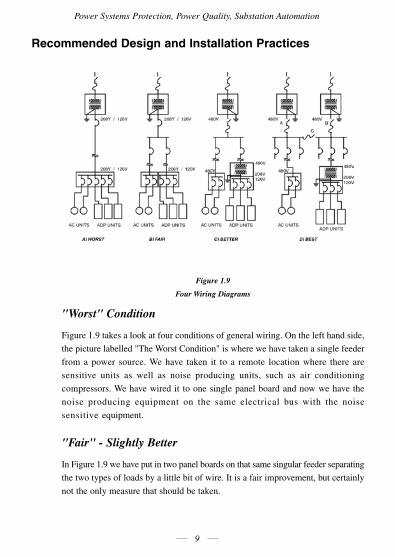
Figure 1.9
Four Wiring Diagrams
"Worst" Condition
Figure1.9takesalookatfourconditionsofgeneralwiring.Onthelefthandside,
the picture labelled "The Worst Condition" is where we have taken a single feeder
from a power source. We have taken it to a remote location where there are
sensitive units as well as noise producing units, such as air conditioning
compressors. We have wired it to one single panel board and now we have the
noise producing equipment on the same electrical bus with the noise
sensitive equipment.
"Fair" - Slightly Better
In Figure 1.9 we have put in two panel boards on that same singular feeder separating
the two types of loads by a little bit of wire. It is a fair improvement, but certainly
not the only measure that should be taken.
The IDC Engineers Pocket Guide
10
"Better" - Gets the Job Done
In the picture labelled "Better" what we have done is introduced the use of the
two-windingtransformertoseparatethesensitiveequipmentfromaprimarybus
which has noise producing equipment on it. This transformer has the low internal
impedance with the ability to act as a buffer for noise which is coming on the
primaryside.Thebufferdoesnotpermitittopassthroughtheflexiblecoupling
of the primary to the secondary side of the transformer.
"Best" - May not be Available
The picture on the far right is certainly the ultimate in design and application. It
involves having multiple feeds, transfer capability and the transformer
downstream of it all. It may not be possible due to electrical restrictions in a given
area, financial considerations or due to space considerations to engage in the best
ofpractices.Butonethingwecanconcentrateonistheuseofthetwo-winding
transformer to help us with the wiring and grounding interfacing that we need
between the power source and the load.
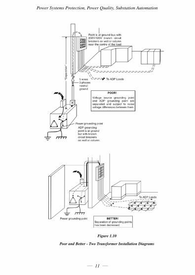
Transformer Location
In Figure 1.10, we have the "Poor to Better" comparison of the use of the isolating
transformer and some understanding of why it works so well in the way that it is
laidout.Youwillnoticeintheupperexampleonthisdrawingthepoorapplication
is where the transformer is located at a considerable distance from the sensitive
equipment. In this particular case the equipment is shown as being a computer
powered by its own circuit breaker panel in a computer room location. The same
application would hold true if it were a computer on a process floor, a computer
that was running a telephone system, a network system of personnel computers or
any other type of digital logic device. The reason why this application is poor is
explainedintheparagraphonthefigure.Thetransformerwithitsgroundingpoint
is at a different location from the grounding point of the sensitive equipment in
the upper picture.
Power Systems Protection, Power Quality, Substation Automation
11
Figure 1.10
Poor and Better - Two Transformer Installation Diagrams
The IDC Engineers Pocket Guide
12
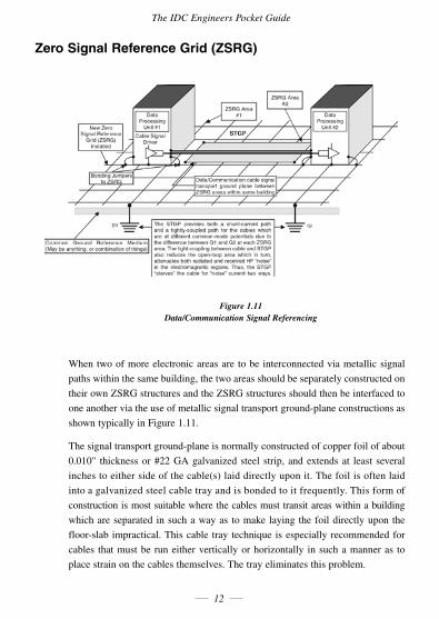
Zero Signal Reference Grid (ZSRG)
Figure 1.11 Data/Communication Signal Referencing
When two of more electronic areas are to be interconnected via metallic signal
paths within the same building, the two areas should be separately constructed on
theirownZSRGstructuresandtheZSRGstructuresshouldthenbeinterfacedto
oneanotherviatheuseofmetallicsignaltransportground-planeconstructionsas
shown typically in Figure 1.11.
Thesignaltransportground-planeisnormallyconstructedofcopperfoilofabout
0.010" thicknessor#22GAgalvanized steel strip, andextendsat least several
inches to either side of the cable(s) laid directly upon it. The foil is often laid
into a galvanized steel cable tray and is bonded to it frequently. This form of
construction is most suitable where the cables must transit areas within a building
which are separated in such a way as to make laying the foil directly upon the
floor-slabimpractical.Thiscable traytechniqueisespeciallyrecommendedfor
cables that must be run either vertically or horizontally in such a manner as to
place strain on the cables themselves. The tray eliminates this problem.
Power Systems Protection, Power Quality, Substation Automation
13
Cablesinstalleduponasignal transportground-planearerequiredtobelaidas
closetothesurfaceoftheground-planeasispractical,soastoreduceopen-loop
couplingareasandtoallowtheelectricalfieldsbetweentheground-planeandthe
cables to have maximum coupling via short paths. This practice significantly
improves the performance of the resultant installation and provides greater immunity
toexternallycoupled"noise"currentelectricalfields.
The popular practice of running metallic cables directly between electronics areas in
buildingsisneveragoodpracticeasitalwaysinvolvesproblemswithcommon-mode
voltagesandcurrentswhicharealwaystobeexpected.Designersshouldstriveto
eliminate the practice of directly interconnected equipment wherever possible in
these cases. The use of fiber optics is clearly suggested as a better method than
using metallic cables between such areas.
In the event that "noise" problems persist in a given cable(s), it is strongly
suggested that a Balun transformer be used at each end of the subject cable as a
means of increasing the common-mode current path's impedance (more
impedance=lesscurrent)withoutaffectingthenormal-modesignalscontained
within the cable. In some cases additional cable shielding may be warranted. In
somecasesadifferentformofcabledriver/receiverdesignmaybeindicated.In
no case, however, should the grounding system be altered as a means of trying to
reduce "noise" problems if the modification either causes violation of the
applicable National Electrical Code requirements or of the UL listing (safety)
requirements of the subject equipment. Equipment must be either made to operate
on the applicable National Electrical Code of Safety Standard acceptable wiring/
grounding or it should be replaced with equipment that will operate in such an
environment without the creation of safety hazards.
We notice that in data communications cable signal transport between two
processing units, these two areas can be interconnected by means of one form or
another of a continuous ground plane that we will call the zero signal reference grid
(ZSRG).Theprocessdescribedhereistoprovideascloseacouplingbetweenthe
signal transport system and this common zero reference grid in order to avoid and
provide immunity toexternallycouplednoiseandelectrical fields. When this is
done the open loop coupling areas are made very small and the electrical fields
between thegroundplaneand thecableswillhavemaximumcouplingviashort
paths and thus offer the greatest protection to the signal circuit.
The IDC Engineers Pocket Guide
14
Chapter 2 Electrical Protection for Power SystemsThe Need for Electrical Protection
It is not economically feasible to design and manufacture electrical equipment
that will never fail in service. Equipment will and does fail, and the only way to
limit further damage to equipment, and to restrict danger to human life, is to provide
fast, reliable electrical protection. The protection of a power system detects
abnormal conditions, localizes faults, and promptly removes the faulty equipment
from service.
Protective Relays
APROTECTIVERELAYisthedevice,whichoperatestodisconnectafaultypart
of the system, thereby protecting the remainder of the system from further damage.
In fact, power protection has the following five main functions as its levels of
discipline and functionality, shown in order of priority.
• Toensuresafetyofpersonnel
• Tosafeguardtheentiresystem
• Toensurecontinuityofsupply
• Tominimizedamage
• Toreduceresultantrepaircosts
All of these requirements make it necessary to ensure early detection, localization,
and rapid isolation of electrical faults and additionally prompt and safe removal
from service of faulty equipment.
The Basic Requirements of Protection
In order to satisfy the above requirements, protection must therefore have the
following qualities:
RELIABILITY :
Tooperateinthepre-determinedmannerwhenanelectricalfaultisdetected.
Power Systems Protection, Power Quality, Substation Automation
15
SELECTIVITY/DISCRIMINATION:
To detect and safely isolate only the faulty item(s).
STABILITY/SECURITY:
To leave all healthy circuits intact and undisturbed and to ensure
continuity of supply.
SENSITIVITY:
To detect even the smallest values of fault current or system abnormalities
andoperatecorrectlyatitspre-setsettings.
SPEED:
To operate speedily when it is required thereby minimizing damage and
ensuring safety to personnel.
Electrical Faults
Electrical faults usually occur due to breakdown of the insulating media between
live conductors or between a live conductor and earth. This breakdown may be
caused by any one or more of several factors, e.g. mechanical damage, overheating,
voltage surges (caused by lightning or switching), ingress of a conducting medium,
ionization of air, deterioration of the insulating media due to an unfriendly
environment or old age, or misuse of equipment.
Fault currents release an enormous amount of thermal energy, and if not cleared
quickly, may cause fire hazards, extensive damage to equipment and risk to
human life.
Switchgear needs to be rated to withstand and break the worst possible fault
current,whichisasolidthree-phaseshort-circuitclosetotheswitchgear.('Solid'
meaning that there is no arc resistance. Normally arc resistance will be present,
butthisvalueisunpredictable,asitwilldependonwhereexactlythefaultoccurs,
theactualarcingdistance, thepropertiesof theinsulatingmediumat thatexact
instance, which will be changing all the time due to the heating effect of the arc,
etc. Therefore, in fault calculations, the arc resistance is ignored, as it is
undeterminable, with the result that the worst case is calculated. The arc
resistance will tend to decrease the fault current.
The IDC Engineers Pocket Guide
16
Transient & Permanent Faults
Transient faults are faults that do not damage the insulation permanently and as
suchallowthecircuittobesafelyre-energizedafterashortperiodoftime.
Atypicalexamplewouldbeaninsulatorflashoverfollowinga lightningstrike,
which would be successfully cleared on opening of the circuit breaker, which
could then be automatically reclosed.
Transient faults occur mainly on outdoor equipment where air is the main
insulating medium.
Permanent faults, as the name implies, are the result of permanent damage to the
insulation of either the transmission medium or the associated equipment attached
to it.
Calculation of Short Circuit Currents
Accurate fault current calculations are normally carried out using an analysis
method called "Symmetrical Components." This method involves the use of higher
mathematics and is based on the principal that any unbalanced set of vectors can
be represented by a set of 3 balanced systems, namely; positive, negative and zero
sequence vectors.
However, for general practical purposes it is possible to achieve a good
approximationof3phaseshortcircuitcurrentsusingsomeverysimplemethods,
which are discussed below.
The short circuit current at the secondary side and close to the transformer, can be
quickly calculated by using the following formula:
short-circuit MVA =
andShort-circuitcurrent where
P =TransformerratinginMVA
X%=InternalReactanceofTransformerin%
I kA =Short-circuitcurrentinkA
kV =TransformersecondaryvoltageinkV
100PX%
Power Systems Protection, Power Quality, Substation Automation
17
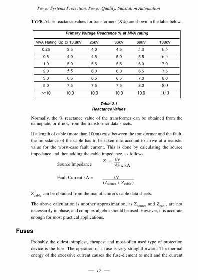
TYPICAL%reactancevaluesfortransformers(X%)areshowninthetablebelow.
Primary Voltage Reactance % at MVA rating
MVA Rating Up to 13.8kV 25kV 36kV 69kV 138kV
0.25 3.5 4.0 4.5 5.0 6.5
0.5 4.0 4.5 5.0 5.5 6.5
1.0 5.0 5.5 5.5 6.0 7.0
2.0 5.5 6.0 6.0 6.5 7.5
3.0 6.5 6.5 6.5 7.0 8.0
5.0 7.5 7.5 7.5 8.0 8.0
>=10 10.0 10.0 10.0 10.0 10.0
Table 2.1Reactance Values
Normally, the % reactance value of the transformer can be obtained from thenameplate, or if not, from the transformer data sheets.
Ifalengthofcable(morethan100m)existbetweenthetransformerandthefault,
the impedance of the cable has to be taken into account to arrive at a realistic
value for the worst-case fault current. This is done by calculating the source
impedance and then adding the cable impedance, as follows:
Source Impedance
FaultCurrentkA= kV (Zsource+Zcable )
Zcablecanbeobtainedfromthemanufacturer'scabledatasheets.
Theabovecalculationisanotherapproximation,asZsourceandZcable are not
necessarilyinphase,andcomplexalgebrashouldbeused.However,itisaccurate
enough for most practical applications.
Fuses
Probably the oldest, simplest, cheapest and most-often used type of protection
device is the fuse. The operation of a fuse is very straightforward: The thermal
energyof theexcessivecurrentcausesthefuse-element tomeltandthecurrent
The IDC Engineers Pocket Guide
18
path is interrupted. Technological developments have served to make fuses more
predictable,fasterandsafer(nottoexplode).
A common misconception about a fuse, is that it will blow as soon as the current
exceedsitsratedvalue(i.e.thevaluestampedonthecartridge).Thisisfarfrom
thetruth.Afusehasatypicalinversetime-currentcharacteristic,muchthesame
asanIDMTrelay.Thepick-upvalueonlystartsatapproximatelytwicetherated
value, and the higher the current, the faster the fuse will blow.
Bynature,fusescanonlydetectfaultsassociatedwithexcesscurrent.Therefore,
a fuse will only blow in earth fault conditions once the current in the faulty phase
has increased beyond the overcurrent value. Therefore, fuses do not offer
adequateearthfaultprotection.Afusehasonlyasingletime-currentcharacteristic,
and cannot be adjusted. In addition, fuses need to be replaced after every
operation.Finally,fusescannotbegivenanexternalcommandtotrip.
Fusesareveryinexpensive.Therefore,theyaresuitabletouseonlesscritical
circuitsandasback-upprotectionshouldthemainprotectionfail,offeringvery
reliablecurrent-limitingfeaturesbynature.
Another advantage of fuses is the fact that they can operate totally independently,
i.e. they do not need a relay with instrument transformers to tell them when to
blow.ThismakesthemespeciallysuitableinapplicationslikeremoteRingMain
Units, etc.
The Relay - Circuit-Breaker Combination
The most versatile and sophisticated type of protection available today, is
undoubtedlytherelay-circuit-breakercombination.Therelayreceivesinformation
regarding the network mainly from the instrument transformers (voltage and current
transformers), detects an abnormal condition by comparing this information to
pre-setvalues,andgivesatrippingcommandtothecircuit-breakerwhensuchan
abnormal condition has been detected. The relay may also be operated by an
externaltrippingsignal,eitherfromotherinstruments,fromaSCADAmaster,or
by human intervention.
The most reliable way to provide auxiliary power to the relay is by way of a
Battery Tripping Unit (BTU). The unit basically consists of a set of batteries
which supplies DC power to the relay and trip circuit. The batteries are kept under
Power Systems Protection, Power Quality, Substation Automation
19
charge by a battery charger, which normally is rated to have enough capacity to
supplythestandingloadoftheswitchgearpanel(relayauxiliarypower,indication
lamps, etc.). When a temporary high current is needed, usually to provide a
circuit-breaker tripping supply, the batteries will supply this, and be recharged
after the event. The batteries then also function as a full back up in case of total
power failure.
TheAC input to the BTU is usually supplied from the panelVT, or from a
lighting transformer.
What often occurs in practice, and which is very bad engineering practice, is to
powertherelayandtripcircuitdirectlyfromthepanelVT.Thiswillfunction
correctly in most instances, but when a really severe three-phase short-circuit
occurs, the voltage of the substation may drop quite dramatically, causing
malfunction of the tripping circuit.
There are other ways to overcome this, like capacitive tripping circuits, and AC
series tripping schemes, but each has its own disadvantages, and none are as
reliable as the DC shunt tripping arrangement.
The circuit breaker opens its main contacts when the tripping signal has been
received, interrupting the current.
From the protection point of view the important parts of the circuit breaker are the
tripcoil,latchingmechanism,maincontactsandauxiliarycontacts.
Circuitbreakersarenormallyfittedwithanumberofauxiliarycontacts,whichare
used, as needed, in a variety of ways in control and protection circuits
Initially, circuit breakers used air as the insulating medium, later insulating oil
(theoilalsoactingasacoolingmedium),andnowadaysvacuumorSF6(sulphur-
hexafluoride)gas.
The connection between the relay and the circuit-breaker trip coil is purely
electrical.Thisusedtobeonepossibleweaklinkinthetripcircuit.Onepopular
method to increase the reliability of the trip circuit for critical substations is to
provideafullback-uptripsupply.Aback-uptripcoil is installedin thecircuit
breaker,withback-upprotection,poweredbyasecond,independentBTU.
The IDC Engineers Pocket Guide
20
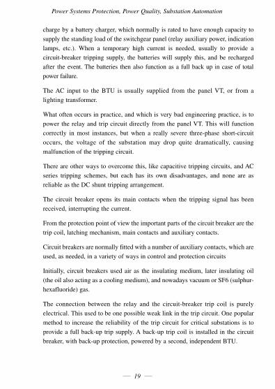
Figure 2.1 illustrates a typical arrangement.
Figure 2.1Arrangement of D. C. Supplies with Two Trip Coils for Each Circuit Breaker
Oftenasecondsetofcontactsofthesamerelayisusedfortheback-upprotection,
which defeats the purpose of having full redundancy somewhat, as the relay itself
then forms the weakest link.
A second method of increasing the reliability of the trip circuit, is to incorporate a
trip circuit supervision relay, which continually monitors the continuity of the trip
circuit, and activates an alarm when an unhealthy trip circuit is detected. One
shortcoming of this method is that it cannot monitor the main protection relay
itself.
Modern relays now have advanced self-monitoring and trip circuit supervision
functionality, activating an alarm when it detects a fault within itself or in the trip
circuit, increasing reliability of the complete trip circuit tremendously.

Power Systems Protection, Power Quality, Substation Automation
21
Circuit Breaker Tripping Times
Thefirstcharacteristicisreferredtoasthe"TRIPPINGTIME"andisexpressed
in cycles.
Modernhigh-speedcircuitbreakershavetrippingtimesbetween3and8cycles.
TheTRIPPING,TOTALBREAKTIMEismadeupasfollows:
• (TrippingTime)OpeningTime:
This represents the time between the instant of application of tripping power
to the instant of mechanical separation of the main contacts.
• (TrippingTime)ArcingTime:
The time between the instant of mechanical separation of the main circuit
breakercontactstotheinstantofarcextinction
The sum of the above: Opening Time + Arcing Time = Breaking Time
Instrument Transformers
The three main tasks of instrument transformers are
• Totransformcurrentsorvoltagesfromausuallyhighvaluetoavalueeasyto
handle for relays and instruments.
• To insulate the relays, metering and instruments from the primary high
voltage system.
• Toprovidepossibilitiesofstandardizingtherelaysandinstrumentsetc.toa
few rated currents and voltages.
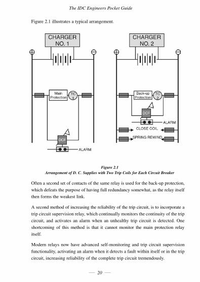
Current Transformer (CT) Magnetization Curve
This curve is the best method of determining Current Transformer (CT) performance.
It is a graph of the amount of magnetizing current required to generate an
open-circuitvoltageattheterminalsoftheunit.Duetothenon-linearityofthe
core iron, it follows the B-H loop characteristic and comprises three regions,
namely the initial region, unsaturated region and saturated region.
The IDC Engineers Pocket Guide
22
Figure 2.2 Typical CT Magnetization Curve.
Knee-Point Voltage
The transition from the unsaturated to the saturated region of the open circuit
excitationcharacteristic isa rathergradualprocess inmostcorematerials. It is
difficult to define this transition anduse ismadeof the so-called "knee-point"
voltage for this purpose.
Itisgenerallydefinedasthevoltageatwhichafurther10%increaseinvoltswill
requirea50%increaseinexcitationcurrent.Formostapplications,itmeansthat
currenttransformerscanbeconsideredasapproximatelylinearuptothispoint.
Metering CTs
Instruments and meters are required to work accurately up to full load current, but
above this it is advantageous to saturate to protect the instruments under fault
conditions.Theythereforehaveaverysharpknee-pointandaspecialnickel-alloymetal
is used, having a very low magnetizing current, in order to achieve the accuracy.
Power Systems Protection, Power Quality, Substation Automation
23
Protection CTs
Protective gear, on the other hand, is concerned with a wide range of currents
fromfaultsettingstomaximumfaultcurrentsmanytimesnormalrating.Larger
errors may be permitted and it is important to ensure that saturation is avoided
wherever possible to ensure positive operation of the relays.
Open Circuiting of CTs
Current transformers generallywork at a low fluxdensity.The core is usually
made of very good metal to give a small magnetizing current. When it is open circuit
the secondary impedance now becomes infinite and the core deeply saturates.
-*-Flashoverwillthenoccur-*-
NEVEROPEN-CIRCUITAC.T.ONLOAD!
As all of the primary current now becomes magnetizing current.
As the ac wave then moves from positive half cycle to the negative half cycle, the
rateofchangeoffluxdφ/dt is so great that very high voltages are induced in the
secondary winding.
CT Specification
A current transformer is normally specified in terms of
• Aratedburdenatratedcurrent.
• Anaccuracyclass.
• Anupperlimitbeyondwhichaccuracyisnotguaranteed.
(KnownastheAccuracyLimitFactor,ALF).
Special (Class X) Current Transformers
These are normally specified for special purpose applications such as differential
protection, where it is important that CTs have matching characteristics.
The IDC Engineers Pocket Guide
24
ForthistypeofCTanexactpointontheMagnetizationCurveisspecified,e.g.
• Ratedprimarycurrent
• Turnsratio
• Ratedkneepointe.m.f.atmaximumsecondaryturns
• Maximumexcitingcurrentatratedkneepointe.m.f.
• Maximumresistanceofsecondarywinding.
Inaddition,theerrorintheturn'sratioshallnotexceed+/-0.25%.
Voltage Transformers
There are two types of voltage transformer used for protection equipment, the
purelyelectro-magnetictype(commonlyreferredtoasaVT)andtheCapacitor
type(referredtoasaCVT).
Magnetic Voltage Transformer
The magnetic voltage transformer is similar to a power transformer and differs
only in so far as a different emphasis is placed on cooling, insulating and
mechanical aspects.
The primary winding has a large number of turns and is connected across the line
voltageeitherline-to-lineorline-to-neutral.
The secondary has fewer turns, consequently as the volts per turn remains
constant, then less voltage and higher currents are obtained.
Outputburdensof500VAperphasearecommon.
Capacitive Transformer
ThecapacitorVTismorecommonlyusedonhighvoltagenetworks.Thecapacitor
allows the injection of a high frequency signal onto the power line conductors to
provide end-to-end communications between substations for distance relays
telemetry/supervisoryandvoicecommunications.
Power Systems Protection, Power Quality, Substation Automation
25
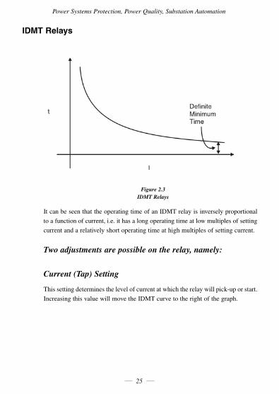
IDMT Relays
Figure 2.3 IDMT Relays
ItcanbeseenthattheoperatingtimeofanIDMTrelayisinverselyproportional
to a function of current, i.e. it has a long operating time at low multiples of setting
current and a relatively short operating time at high multiples of setting current.
Two adjustments are possible on the relay, namely:
Current (Tap) Setting
Thissettingdeterminesthelevelofcurrentatwhichtherelaywillpick-uporstart.
IncreasingthisvaluewillmovetheIDMTcurvetotherightofthegraph.
The IDC Engineers Pocket Guide
26
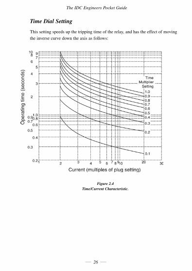
Time Dial Setting
This setting speeds up the tripping time of the relay, and has the effect of moving
theinversecurvedowntheaxisasfollows:
Figure 2.4 Time/Current Characteristic.
Power Systems Protection, Power Quality, Substation Automation
27
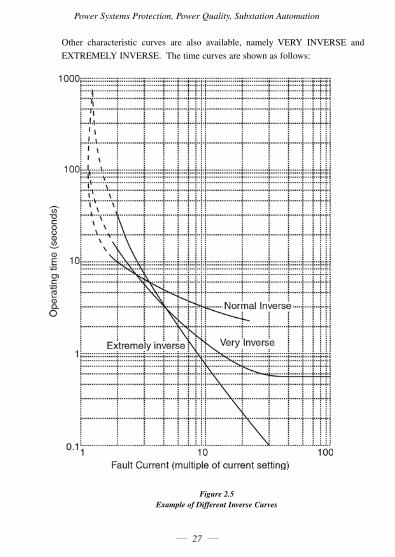
Other characteristic curves are also available, namely VERY INVERSE and
EXTREMELYINVERSE.Thetimecurvesareshownasfollows:
Figure 2.5 Example of Different Inverse Curves
The IDC Engineers Pocket Guide
28
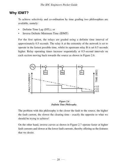
Why IDMT?
To achieve selectivity and co-ordination by time grading two philosophies are
available, namely:
• DefiniteTimeLag(DTL),or
• InverseDefiniteMinimumTime(IDMT)
For the first option, the relays are graded using a definite time interval of
approximately0.5seconds.TherelayAattheextremityofthenetworkissetto
operate in the fastest possible time, whilst its upstream relay B is set 0.5 seconds
higher. Relay operating times increase sequentially at 0.5-second intervals on
each section moving back towards the source as shown in Figure 2.6.
Figure 2.6 Definite Time Philosophy.
The problem with this philosophy is the closer the fault to the source, the higher
thefaultcurrent,theslowertheclearingtime-exactlytheoppositetowhatwe
shouldbetryingtoachieve!
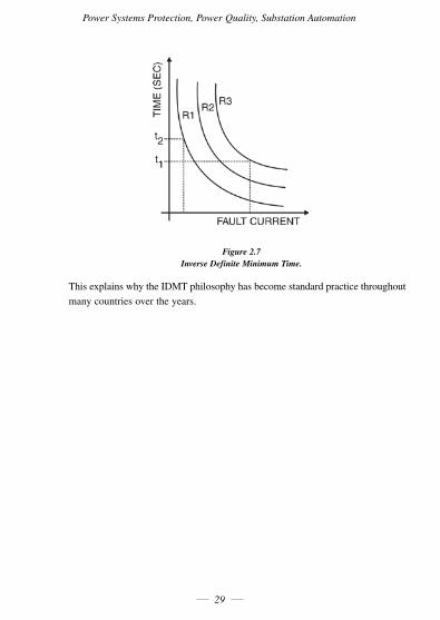
Ontheotherhand,inversecurvesasshowninFigure2.7operatefasterathigher
fault currents and slower at the lower fault currents, thereby offering us the features
that we desire.
Power Systems Protection, Power Quality, Substation Automation
29
Figure 2.7 Inverse Definite Minimum Time.
ThisexplainswhytheIDMTphilosophyhasbecomestandardpracticethroughout
many countries over the years.
The IDC Engineers Pocket Guide
30
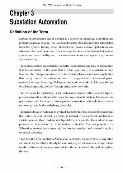
Chapter 3 Substation AutomationDefinition of the Term
Substation Automation can be defined as a system for managing, controlling and
protectingapowersystem.Thisisaccomplishedbyobtainingreal-timeinformation
from the system, having powerful local and remote control applications and
advanced electrical protection. The core ingredients of a Substation Automation
system are local intelligence, data communications and supervisory control
and monitoring.
The term Substation Automation is actually too restrictive and may be misleading.
It is too restrictive in the sense that it refers specifically to a substation only.
However, the concepts encompassed in the definition have a much wider application
than being limited only to substations. It is applicable to electrical power
networksatlarge,fromHighVoltagetransmissionnetworks,toMediumVoltage
distributionnetworks,toLowVoltagereticulationnetworks.
The term may be misleading in that automation usually refers to some type of
process automation, whereas the concepts involved in Substation Automation are
quite unique and far removed from process automation, although there is some
common ground in the underlying principles.
The term Substation Automation evolved due to the fact that most of the equipment
that forms the core of such a system, is located in an electrical substation or
switchroom, and these modern, intelligent devices ensure that the need for human
presence or intervention in a substation is limited. The components of a
Substation Automation system aim to protect, monitor and control a typical
electrical substation.
Therefore the term Substation Automation is probably as descriptive as any other,
and due to the fact that it already became virtually an international accepted term
for the multitude of concepts involved, it is the term that will be used throughout
thetext.
Power Systems Protection, Power Quality, Substation Automation
31
(Note:Theterm"substation"willbeusedthroughoutthetexttodescribemainlya
building housing electrical switchgear, but it may also include switchgear housed in
somesortofenclosure,forexampleastand-aloneRingMainUnit,etc.)
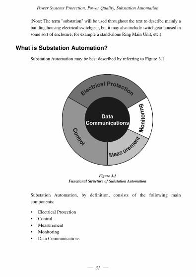
What is Substation Automation?
Substation Automation may be best described by referring to Figure 3.1.
Figure 3.1 Functional Structure of Substation Automation
Substation Automation, by definition, consists of the following main
components:
• ElectricalProtection
• Control
• Measurement
• Monitoring
• DataCommunications
The IDC Engineers Pocket Guide
32
Electrical Protection
Electrical Protection is still one of the most important components of any electrical
switchgear panel, in order to protect the equipment and personnel, and to limit
damage in case of an electrical fault.
Electrical protection is a local function, and should be able to function independently
of the Substation Automation system if necessary, although it is an integral part
of Substation Automation under normal conditions. The functions of electrical
protection should never be compromized or restricted in any Substation
Automation system.
Control
Control includes local and remote control. Local control consists of actions the
controldevicecanlogicallytakebyitself,forexamplebayinterlocking,switching
sequences and synchronising check. Human intervention is limited and the risk of
human error is greatly reduced.
Local control should also continue to function even without the support of the rest
of the Substation Automation system.
Commandscanbegivendirectly to theremotecontrolleddevices, forexample
open or close a circuit breaker. Relay settings can be changed via the system, and
requests for certain information can be initiated form the SCADA station(s). This
eliminates the need for personnel to go to the substation to perform switching
operations, and switching actions can be performed much faster, which is a
tremendous advantage in emergency situations.
A safer working environment is created for personnel, and huge production losses
may be prevented. In addition, the operator or engineer at the SCADA terminal
has a holistic overview of what is happening in the power network throughout the
plantorfactory,improvingthequalityofdecision-making.
Power Systems Protection, Power Quality, Substation Automation
33
Measurement
A wealth of real-time information about a substation or switchgear panel is
collected,whicharetypicallydisplayedinacentralcontrolroomand/orstoredin
acentraldatabase.Measurementconsistsof:
• Electrical measurements (including metering) - voltages, currents, power,
power factor, harmonics, etc.
• Otheranalogmeasurements,eg.transformerandmotortemperatures
• Disturbancerecordingsforfaultanalyzes
This makes it unnecessary for personnel to go to a substation to collect information,
again creating a safer work environment and cutting down on personnel workloads.
Thehugeamountofreal-timeinformationcollectedcanassist tremendously in
doing network studies like load flow analyzes, planning ahead and preventing
major disturbances in the power network, causing huge production losses.
Note:Theterm'measurement'isnormallyusedintheelectricalenvironmenttorefer
tovoltage,currentandfrequency,while'metering'isusedtorefertopower,
reactive power, and energy (kWh). The different terms originated due to the
fact that very different instruments were historically used for measurement
and metering. Nowadays the two functions are integrated in modern devices,
with no real distinction between them, hence the terms 'measurement' and
'metering'areusedinterchangeablyinthetext.Accuratemeteringforbilling
purposes is still performed by dedicated instruments.
Monitoring
• Sequence-of-EventRecordings
• Status and condition monitoring, including maintenance information, relay
settings, etc.
This information can assist in fault analyzes, determining what happened when,
where and in what sequence. This can be used effectively to improve the efficiency
of the power system and the protection. Preventative maintenance procedures can
be utilized by the condition monitoring information obtained.
The IDC Engineers Pocket Guide
34
Data Communication
Data communication forms the core of any Substation Automation system, and is
virtually the glue that holds the system together. Without communications, the
functions of the electrical protection and local control will continue, and the local
device may store some data, but there can be no complete Substation Automation
system functioning. The form of communications will depend on the
architecture used, and the architecture may, in turn, depend on the form of
communication chosen.
Substation Automation Architecture
Different architectures exist today to implement the components of Substation
Automation in practice. It is important to realize that not one single layout can
exclusively illustrate a Substation Automation system. However, the most
advanced systems today are developing more and more towards a common basic
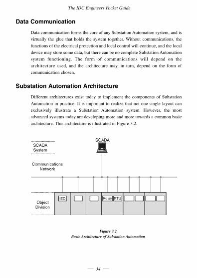
architecture. This architecture is illustrated in Figure 3.2.
Figure 3.2 Basic Architecture of Substation Automation
Power Systems Protection, Power Quality, Substation Automation
35
The modern system consists of three main divisions:
Object Division
The object division of the Substation Automation system consists of Intelligent
Electronic Devices (IEDs), modern, 3rd generation microprocessor based relays
and/orRemoteTerminalUnits(RTUs).(PLCsalsocontinuetoplayanimportant
role in some systems.) They receive analog inputs from the Current Transformers
(CTs), Voltage Transformers (VTs) and transducers in the various switchgear
panels, as well as digital inputs from auxiliary contacts, other field devices or
IEDs, or the SCADA Master. They are able to perform complex logical and
mathematical calculations andprovide anoutput either to theSCADAMaster,
other field instruments or IEDs, or back to the switchgear to perform some
command,forexampleopenacircuitbreaker.
The component division consists of the process level (field information from CTs,
VTs,etc)andthebaylevel(localintelligenceintheformofIEDs,RTUs,etc).
The Communications Network
The Communications Network (comms network for short) is virtually the nervous
system of Substation Automation. The comms network ensures that raw data,
processedinformationandcommandsarerelayedquickly,effectivelyanderror-free
among the various field instruments, IEDs and the SCADA system. The physical
mediumwillgenerallybefiber-opticcablesinmodernnetworks,althoughsome
copperwiringwillstillexistbetweenthevariousdevicesinsideasubstation.
Thecommsnetworkneedstobean'intelligent'subsysteminitsownrightto
performthefunctionsrequiredofit,andisnotmerelyanetworkoffiber-optic
and copper wiring.
The communication network serves as the interface between the bay level and the
SCADA station level, which might be a SCADA master station in the substation
itself, or remotely in a central control room.
SCADA Master
The SCADA (Supervisory Control And Data Acquisition) master station(s) forms
the virtual brain of the Substation Automation system. The SCADA master
The IDC Engineers Pocket Guide
36
receives data and information from the field, decides what to do with it, stores it
(directlyoraftersomeformofprocessing),andissuesrequestsand/orcommands
to the remote devices. Therefore, the SCADA master is effectively in control of
the complete Substation Automation system.
Nowadays, a SCADA master consists simply of an advanced, reliable PC
or workstation (with its peripheral and support hardware) and a SCADA
software package.
A SCADA master station may be installed in each substation of a power
transmission network (station level), with all the substation SCADA stations
forming part of a LAN or WAN (network level); or one SCADA master station
may be directly in control of several substations, eliminating the station level.
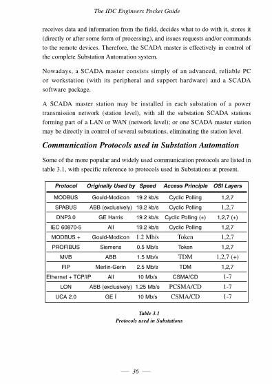
Communication Protocols used in Substation Automation
Some of the more popular and widely used communication protocols are listed in
table 3.1, with specific reference to protocols used in Substations at present.
Protocol Originally Used by Speed Access Principle OSI Layers
MODBUS Gould-Modicon 19.2 kb/s Cyclic Polling 1,2,7
SPABUS ABB (exclusively) 19.2 kb/s Cyclic Polling 1,2,7
DNP3.0 GE Harris 19.2 kb/s Cyclic Polling (+) 1,2,7 (+)
IEC 60870-5 All 19.2 kb/s Cyclic Polling 1,2,7
MODBUS + Gould-Modicon 1.2Mb/s Token 1,2,7
PROFIBUS Siemens 0.5 Mb/s Token 1,2,7
MVB ABB 1.5 Mb/s TDM 1,2,7(+)
FIP Merlin-Gerin 2.5 Mb/s TDM 1,2,7
Ethernet + TCP/IP All 10 Mb/s CSMA/CD 1-7
LON ABB (exclusively) 1.25 Mb/s PCSMA/CD 1-7
UCA 2.0 GE Ï 10 Mb/s CSMA/CD 1-7
Table 3.1 Protocols used in Substations
Power Systems Protection, Power Quality, Substation Automation
37
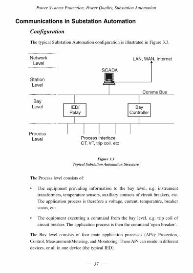
Communications in Substation Automation
Configuration
The typical Substation Automation configuration is illustrated in Figure 3.3.
Figure 3.3 Typical Substation Automation Structure
The Process level consists of:
• The equipment providing information to the bay level, e.g. instrument
transformers,temperaturesensors,auxiliarycontactsofcircuitbreakers,etc.
The application process is therefore a voltage, current, temperature, breaker
status, etc.
• Theequipmentexecutingacommand from thebay level, e.g. tripcoilof
circuitbreaker.Theapplicationprocessisthenthecommand'openbreaker'.
The Bay level consists of four main application processes (APs): Protection,
Control,Measurement/Metering,andMonitoring.TheseAPscanresideindifferent
devices, or all in one device (the typical IED).
The IDC Engineers Pocket Guide
38
The Station level consists of the Station SCADA (optional) and possibly a gateway
or communications processor. The importance of the Station SCADA will depend
on the specific application. In large transmission substations, this will form the
main SCADA for the specific substation, with several SCADA systems forming
anetwork.Ontheotherhand,foradistributionsubstation,theStationSCADA
may be dispensed with, and only a gateway will be required to connect the
substation to the network and to the main SCADA.
The network level may consist of a central SCADA, to which each substation is
connected,and/oraLAN,MAN,WANortheInternet.
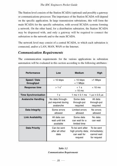
Communication Requirements
The communication requirements for the various applications in substation
automation will be evaluated in this section according to the following attributes:
Performance Low Medium High
Speed / Data < 10 kbps > 10 kbps >1 Mbps throughput < 1 Mbps
Response time > 1 s1 < 1 s < 10 ms > 10 ms
Time Synchronisation 1 s 1 ms + 0.1 ms 1 µs + 0.5 µs
Avalanche Handling No data through- Some data All data put required during through-put through-put avalanche required required
Data Integrity Some errors Limited errors No errors allowed allowed allowed
Link Availability All data can Some data No data wait until link can wait for a can wait available limited time
Data Priority Can be sent To be sent after To be sent after all other high priority data; immediately; data can wait for cannot wait request for request
Table 3.2
Communication Requirements
Power Systems Protection, Power Quality, Substation Automation
39
Appendix A Glossary of Terms
10BASE2 IEEE802.3 (or Ethernet) implementation on thin coaxial cable (RG58/AU).
10BASE5 IEEE802.3(orEthernet)implementationonthickcoaxialcable.
10BASET IEEE802.3 (or Ethernet) implementation on unshielded 22AWGtwistedpaircable.
A/DConversionTime Thisisthelengthoftimeaboardrequirestoconvertananalogsignal into a digital value. The theoretical maximum speed (conversions/ second)istheinverseofthisvalue.SeeSpeed/TypicalThroughput.
A/D AnalogtoDigitalconversion.
Absolute Addressing A mode of addressing containing both the instruction and location (address) of data.
Accuracy Closeness of indicated or displayed value to the ideal measured value.
ACK Acknowledge(ASCII-controlF).
Acknowledge A handshake line or protocol code which is used by the receiving device to indicate that it has read the transmitted data.
Active Device Device capable of supplying current for a loop.
Active Filter A combination of active circuit devices (usually amplifiers), with passive circuit elements (resistors and capacitors), which have characteristics that more closely match ideal filters than do passive filters.
Actuator Control element or device used to modulate (or vary) a process parameter.
Address A normally unique designator for location of data or the identity of a peripheral device which allows each device on a single communications line to respond to its own message.
Address Register A register that holds the address of a location containing a data item called for by an instruction.
AFC Automatic Frequency Control. The circuit in a radio receiver that automatically keeps the carrier frequency centred in the passband of the filters and demodulators.
AGC Automatic Gain Control. The circuit in a radio that automatically keeps the carrier gain at the proper level.
The IDC Engineers Pocket Guide
40
Algorithm Can be used as a basis for writing a computer program. This is a set of rules with a finite number of steps for solving a problem.
Alias Frequency A false lower frequency component that appears in data reconstructed from original data acquired at an insufficient sampling rate (less thantwotimesthemaximumfrequencyoftheoriginaldata).
ALU see Arithmetic Logic Unit.
AmplitudeModulation A modulation technique (also referred to asAM orASK) used to allow data to be transmitted across an analog network, such as a switched telephone network. The amplitude of a single (carrier) frequency is varied or modulated between two levels; one for binary 0 and one for binary 1.
Analog Acontinuousreal-timephenomenoninwhichtheinformationvalues are represented in a variable and continuous waveform.
Analog Input Board Printed Circuit Board which converts incoming analog signals to digital values.
ANSI American National Standards Institute. The principle standards development body in the USA.
Apogee The point in an elliptical orbit that is furtherest from earth.
Appletalk A proprietary computer networking standard initiated by Apple Computer for use in connecting the Macintosh range of computers and peripherals (including Laser Writer printers).
Thisstandardoperatesat230kilobits/second.
Application Program A sequence of instructions written to solve a specific problem facing organisational management.
Theseprogramsarenormallywritteninahigh-levellanguageand draw on resources of the operating system and the computer hardware inexecutingitstasks.
ApplicationLayer The highest layer of the seven layer ISO/OSI Reference Model structure, which contains all user or application programs.
Arithmetic Logic Unit The element(s) in a processing system that perform(s) the mathematical functions such as addition, subtraction, multiplication, division, inversion,AND,OR,NANDandNOR.
ARP Address Resolution Protocol. A Transmission Control Protocol/ Internet Protocol (TCP/IP) process that maps an IP address to Ethernetaddress,requiredbyTCP/IPforusewithEthernet.
ARQ Automatic Request for Transmission. A request by the receiver for the transmitter to retransmit a block or a frame because of errors detected in the originally received message.
AS Australian Standard.
Power Systems Protection, Power Quality, Substation Automation
41
ASCII American Standard Code for Information Interchange. A universal standard for encoding alphanumeric characters into 7 or 8 binary bits. Drawn up by ANSI to ensure compatibility between different computer systems.
ASIC Application Specific Integrated Circuit.
ASK AmplitudeShiftKeying.SeeAmplitudeModulation.
ASN.1 Abstract Syntax Notation One. An abstract syntax used to define the structure of the protocol data units associated with a particular protocol entity.
Asynchronous Communications in which characters can be transmitted at an arbitrary, unsynchronised time, and where the time intervals between transmitted characters may be of varying lengths.
Communication is controlled by start and stop bits at the beginning and end of each character.
Attenuation The decrease in signal magnitude or strength between two points.
Attenuator A passive network that decreases the amplitude of a signal (without introducing any undesirable characteristics to the signals such as distortion).
AUI CABLE Attachment Unit Interface Cable. Sometimes called the drop cable to attach terminals to the transceiver unit.
Auto Tracking Antenna A receiving antenna that moves in synchronism with the transmitting device which is moving (such as a vehicle being telemetered).
Autoranging An autoranging board can be set to monitor the incoming signal and automatically select an appropriate gain level based on the previous incoming signals.
AWG AmericanWireGauge.
BackgroundProgram Anapplicationprogramthatcanbeexecutedwheneverthefacilities of the system are not needed by a higher priority program.
Backplane A panel containing sockets into which circuit boards (such as I/O cards, memory boards and power supplies) can be plugged.
Balanced Circuit A circuit so arranged that the impressed voltages on each conductor of the pair are equal in magnitude but opposite in polarity with respect to a defined reference.
BandPassFilter A filter that allows only a fixed range of frequencies to pass through. All other frequencies outside this range (or band) are sharply reduced in magnitude.
Band Reject A circuit that rejects a defined frequency band of signals while passing all signals outside this frequency range (both lower than and higher than).
The IDC Engineers Pocket Guide
42
Bandwidth The range of frequencies available, expressed as the difference between the highest and lowest frequencies, in hertz (cycles per second, abbreviated Hz).
Bar Code Symbol An array of rectangular parallel bars and spaces of various widths designed for the labelling of objects with unique identifications. A bar code symbol contains a leading quiet zone, a start character, one or more data characters including, in some cases, a check character, a stop character, and a trailing quiet zone.
Base Address A memory address that serves as the reference point. All other points are located by offsetting in relation to the base address.
Base Band Base Band operation is the direct transmission of data over a transmission medium without the prior modulation on a high frequency carrier band.
Base Loading An inductance situated near the bottom end of a vertical antenna to modify the electrical length. This aids in impedance matching.
Baud Unit of signalling speed derived from the number of events per second (normally bits per second). However, if each event has more than one bit associated with it, the baud rate and bits per second are not equal.
Baudot Data transmission code in which five bits represent one character. Sixty-fouralphanumericcharacterscanberepresented.
BCC Block Check Character. Error checking scheme with one check character;agoodexamplebeingBlockSumCheck.
BCD Binary Coded Decimal. A code used for representing decimal digits in a binary code.
BEL Bell(ASCIIforcontrol-G).
BERT/BLERT BitErrorRate/BlockErrorRateTesting.Anerrorcheckingtechnique that compares a received data pattern with a known transmitted data pattern to determine transmission line quality.
Bifilar Two conducting elements used in parallel (such as two parallel wires wound on a coil form).
Binary Coded Decimal (BCD) A code used for representing decimal digits in a binary code.
BIOS The basic input/output system for the computer, usually firmware- based. This program handles the interface with the PC hardware andisolatestheOperatingSoftware(OS)fromthelow-levelactivities of the hardware. As a result, application software becomes more independent of the particular specifications of the hardware on which it runs, and hence more portable.
Power Systems Protection, Power Quality, Substation Automation
43
BipolarRange/Inputs A signal range that includes both positive and negative values. Bipolar inputs are designed to accept both positive and negative voltages.(Example:±5V).
Bisynchronous Transmission See BSC.
Bit Stuffing with A technique used to allow pure binary data to be transmitted on aZeroBitInsertion synchronous transmission line. Each message block (frame) is encapsulated between two flags which are special bit sequences. Then if the message data contains a possibly similar sequence, an additional (zero) bit is inserted into the data stream by the sender, and is subsequently removed by the receiving device. The transmission method is then said to be data transparent.
BIT (Binary Digit) Derived from "BInary DigiT", a one or zero condition in the binary system.
Bits&Bytes Onebit isonebinarydigit, eitherabinary0or1.Onebyte is the amount of memory needed to store each character of information (text or numbers). There are eight bits to one byte (or character), and there are 1024 bytes to one kilobyte (KB). There are 1024 kilobytestoonemegabyte(MB).
Block Inblock-structuredprogramminglanguages,asectionofprogramming languages or a section of program coding treated as a unit.
Block Sum Check This is used for the detection of errors when data is being transmitted. It comprises a set of binary digits (bits) which are the modulo 2 sum of the individual characters or octets in a frame (block) or message.
BNC Bayonettypecoaxialcableconnector.
bps Bits per second. Unit of data transmission rate.
Bridge Adevice toconnect similar sub-networkswithout itsownnetwork address. Used mostly to reduce the network load.
Broad Band A communications channel that has greater bandwidth than a voice grade line and is potentially capable of greater transmission rates.
Broadcast A message on a bus intended for all devices which requires no reply.
BS Backspace(ASCIIControl-H).
BS British Standard.
BSC Bisynchronous Transmission. A byte or character oriented communication protocol that has become the industry standard (created by IBM). It uses a defined set of control characters for synchronised transmission of binary coded data between stations in a data communications system.
The IDC Engineers Pocket Guide
44
BubbleMemory Describes a method of storing data in memory where data is represented as magnetized spots called magnetic domains that rest on a thin film of semiconductor material. Normally used in high- vibration,high-temperatureorotherwiseharshindustrialenvironments.
Buffer An intermediate temporary storage device used to compensate for a difference in data rate and data flow between two device (also called a spooler for interfacing a computer and a printer).
BurstMode A high speed data transfer in which the address of the data is sent followed by back to back data words while a physical signal is asserted.
Bus A data path shared by many devices, with one or more conductors for transmitting signals, data or power.
Byte A term referring to eight associated bits of information; sometimes called a "character".
CacheMemory A fast buffer memory that fits between the CPU and the slower main memory to speed up CPU requests for data.
Capacitance (mutual) The capacitance between two conductors with all other conductors, including shield, short circuited to the ground.
Capacitance Storage of electrically separated charges between two plates having different potentials. The value is proportional to the surface area of the plates and inversely proportional to the distance between them.
Cascade Two or more electrical circuits in which the output of one is fed intotheinputofthenextone.
Cassegrain Antenna Parabolic antenna that has a hyperbolic passive reflector situated at the focus of the parabola.
CCD Charge-CoupledDevice(camera).
CCIR Comité Consultatif Internationale des Radiocommunications.
CCITT Consultative Committee International Telegraph and Telephone. An international association that sets worldwide standards (e.g. V.21, V.22,V.22bis).
CellularPolyethylene Expanded or "foam" polyethylene consisting of individual closed cells suspended in a polyethylene medium.
CGA Color Graphics Adapter. A computer standard utilising digital signalsofferingaresolutionof320by200pixelsandapaletteof 16 colors.
ChannelSelector InanFMdiscriminatortheplug-inmodulewhichcausesthedevice to select one of the channels and demodulate the subcarrier to recover data.
Character Letter, numeral, punctuation, control figure or any other symbol contained in a message.
Power Systems Protection, Power Quality, Substation Automation
45
Characteristic The impedance that, when connected to the output terminals of a Impedance transmission line of any length, makes the line appear infinitely long. The ratio of voltage to current at every point along a transmission line on which there are no standing waves.
Clock The source of timing signals for sequencing electronic events such as synchronous data transfer or CPU operation in a PC.
Clock Pulse A rising edge, then a falling edge (in that order) such as applied to theclockinputofan8254timer/counter.
Clock The source(s) of timing signals for sequencing electronic events eg synchronous data transfer.
Closed Loop A signal path that has a forward route for the signal, a feedback network for the signal and a summing point.
CMRR CommonModeRejectionRatio-Adataacquisition’sboard'sability to measure only the voltage difference between the leads of a transducer, rejectingwhat the leads have in common. The higher the CMRR,thebettertheaccuracy.
CMV CommonModeVoltage.
CNR Carrier to Noise Ratio. An indication of the quality of the modulated signal.
Cold-junction Thermocouplemeasurementscaneasilybeaffectedbytheinterface Compensation the thermocouples are connected to. Cold-junction compensation circuitry compensates for inaccuracies introduced in the conversion process.
Collector The voltage source in a transistor with the base as the control source and the emitter as the controlled output.
Collision The situation when two or more LAN nodes attempt to transmit at the same time.
Common Carrier A private data communications utility company that furnishes communications services to the general public.
CommonModeSignal Thecommonvoltagetothetwopartsofadifferentialsignalapplied to a balanced circuit.
Commutator A device used to effect time-division multiplexing by repetitive sequential switching.
Compiler A program to convert high-level source code (such as BASIC) to machinecode-executableform,suitablefortheCPU.
CompositeLink Thelineorcircuitconnectingapairofmultiplexersorconcentrators; thecircuitcarryingmultiplexeddata.
Composite A video signal that contains all the intensity, color and timing information necessary for a video product.
The IDC Engineers Pocket Guide
46
Conical Scan Antenna An automatic tracking antenna system in which the beam is steered in a circular path so that it forms a cone.
Contention The facility provided by the dial network or a data PABX which allows multiple terminals to compete on a first come, first served basis for a smaller number of computer ports.
Control System A system in which a series of measured values are used to make a decision on manipulating various parameters in the system to achieve a desired value of the original measured values.
Convolution An image enhancement technique in which each pixel is subjected to a mathematical operation that groups it with its nearest neighbours and calculates its value accordingly.
Correlator A device which compares two signals and indicates the similarity between the two signals.
Counter/TimerTrigger On-boardcounter/timercircuitrycanbesettotriggerdataacquisition atauser-selectablerateandforaparticularlengthoftime.
CounterDataRegister The 8-bit register of an (8254 chip) timer/counter that corresponds tooneofthetwobytesinthecounter'soutputlatchforreadoperations and count register for write operations.
CPU Central Processing Unit.
CR CarriageReturn(ASCIIcontrol-M).
CRC Cyclic Redundancy Check. An error-checking mechanism using a polynomial algorithm based on the content of a message frame at the transmitter and included in a field appended to the frame. At the receiver, it is then compared with the result of the calculation that is performedbythereceiver.AlsoreferredtoasCRC-16.
Cross Talk A situation where a signal from a communications channel interferes withanassociatedchannel'ssignals.
Crossed Pinning Wiring configuration that allows two DTE or DCE devices to communicate. Essentially it involves connecting pin 2 to pin 3 of the two devices.
Crossover In communications, a conductor which runs through the cable and connects to a different pin number at each end.
Crosstalk A situation where a signal from a communications channel interferes withanassociatedchannel'ssignals.
CSMA/CD CarrierSenseMultipleAccess/CollisionDetection.
When two devices transmit at the same time on a local area
network,they both cease transmission and signal that a collision has occurred. Each then tries again after waiting for a random time period.
Power Systems Protection, Power Quality, Substation Automation
47
Current Sink This is the amount of current the board can supply for digital output signals.With10-12mAormoreofcurrentsinkcapability,aboard canturnrelaysonandoff.DigitalI/Oboardswithlessthan10-12mA of sink capability are designed for data transfer only, not for hardware power relay switching.
Current Loop A communication method that allows data to be transmitted over a longer distance with a higher noise immunity level than with the standardRS-232Cvoltagemethod.
A mark (a binary 1) is represented by current; and a space (or binary 0) is represented by the absence of current.
Current Inputs A board rated for current inputs can accept and convert analog current levels directly, without conversion to voltage.
D/A DigitaltoAnalog.
DAS Data Acquisition System.
Data Integrity A performance measure based on the rate of undetected errors.
DataReduction Theprocessofanalysingalargequantityofdatainordertoextract some statistical summary of the underlying parameters.
DataLinkLayer This corresponds to layer 2 of the ISO Reference Model for open systems interconnection. It is concerned with the reliable transfer of data (no residual transmission errors) across the data link being used.Data Integrity A performance measure based on the rate of undetected errors.
Datagram A type of service offered on a packet-switched data network. A datagram is a self contained packet of information that is sent through the network with minimum protocol overheads.
dBi A unit that is used to represent the gain of an antenna compared to the gain of an isotropic radiator.
dBm Asignallevelthatiscomparedtoa1-mWreference.
dBmV Asignalamplitudethatiscomparedtoa1-mVreference.
dBW Asignalamplitudethatiscomparedtoa1-Wattreference.
DCE Data Communications Equipment. Devices that provide the functions required to establish, maintain and terminate a data transmission connection. Normally it refers to a modem.
Decibel A logarithmic measure of the ratio of two signal levels where dB = 20log10 V1/V2. Being a ratio, it has no units of measure.
Decibel (dB) A logarithmic measure of the ratio of two signal levels where dB = 20log10 V1/V2 or where dB = 10log10 P1/P2 and where V refers toVoltage or P refers to Power. Note that it has no unit of measure.
The IDC Engineers Pocket Guide
48
Decoder A device that converts a combination of signals into a single signal representing that combination.
Decommutator Equipmentforthedemultiplexingofcommutatedsignals.
Default A value or setup condition assigned automatically unless another is specified.
Delay Distortion Distortion of a signal caused by the frequency components making up the signal having different propagation velocities across a transmission medium.
DES Data Encryption Standard.
Deviation A movement away from a required value.
DFB Display Frame Buffer.
Diagnostic Program A utility program used to identify hardware and firmware defects related to the PC.
Dielectric Constant (E) The ratio of the capacitance using the material in question as the dielectric, to the capacitance resulting when the material is replaced by air.
Differential See Number of channels.
Digital A signal which has definite states (normally two).
Digitize The transformation of an analog signal to a digital signal.
DIN Deutsches Institut Fur Normierung.
DIP Acronym for dual in line package referring to integrated circuits and switches.
Diplexing A device used to allow simultaneous reception or transmission of two signals on a common antenna.
DirectMemoryAccess Atechniqueoftransferringdatabetweenthecomputermemoryand adeviceonthecomputerbuswithouttheinterventionofthemicro- processor.AlsoabbreviatedtoDMA.
Discriminator Hardware device to demodulate a frequency modulated carrier or subcarrier to produce analog data.
Dish Antenna An antenna in which a parabolic dish acts a reflector to increase the gain of the antenna.
Dish ConcaveantennareflectorforuseatVHForhigherfrequencies.
Diversity Reception Two or more radio receivers connected to different antennas to improve signal quality by using two different radio signals to transfer the information.
DLE Data Link Escape (ASCII character).
DMA DirectMemoryAccess.
Power Systems Protection, Power Quality, Substation Automation
49
DNA Distributed Network Architecture.
Doppler The change in observed frequency of a signal caused by the emitting device moving with respect to the observing device.
Downlink The path from a satellite to an earth station.
DPI Dots per Inch.
DPLL Digital Phase Locked Loop.
DR Dynamic Range. The ratio of the full scale range (FSR) of a data converter to the smallest difference it can resolve. DR = 2n where n is the resolution in bits.
DRAM DynamicRandomAccessMemory.SeeRAM.
Drift Agradualmovementawayfromthedefinedinput/outputcondition over a period of time.
Driver Software A program that acts as the interface between a higher level coding structure and the lower level hardware/firmware component of a computer.
DSP Digital Signal Processing.
DSR DataSetReady.AnRS-232modem interfacecontrol signalwhich indicates that the terminal is ready for transmission.
DTE Data Terminal Equipment. Devices acting as data source, data sink, or both.
Dual-portedRAM Allows acquired data to be transferred from on-board memory to thecomputer'smemorywhiledataacquisitionisoccurring.
Duplex The ability to send and receive data over the same communications line.
DynamicRange The difference in decibels between the overload or maximum and minimum discernible signal level in a system.
EBCDIC ExtendedBinaryCodedDecimalInterchangeCode.An8-bitcharacter code used primarily in IBM equipment. The code allows for 256 different bit patterns.
EEPROM Electrically Erasable Programmable Read Only Memory. This memory unit can be erased by applying an electrical signal to the EEPROMandthenreprogrammed.
EGA EnhancedGraphicsAdapter.Acomputerdisplaystandardthatprovides a resolution of 640 by 350 pixels, a palette of 64 colors, and the ability to display as many as 16 colors at one time.
EIA Electronic Industries Association. An organisation in the USA specialising in the electrical and functional characteristics of interface equipment.
The IDC Engineers Pocket Guide
50
EIA-232-C Interface between DTE and DCE, employing serial binary data exchange.Typicalmaximumspecificationsare15mat19200Baud.
EIA-423 Interface between DTE and DCE, employing the electrical characteristics of unbalanced voltage digital interface circuits.
EIA-449 General purpose 37 pin and 9 pin interface for DCE and DTE employing serial binary interchange.
EIA-485 The recommended standard of the EIA that specifies the electrical characteristics of drivers and receivers for use in balanced digital multipoint systems.
EIRP Effective Isotropic Radiated Power. The effective power radiated from a transmitting antenna when an isotropic radiator is used to determine the gain of the antenna.
EISA Enhanced Industry Standard Architecture.
EMI/RFI Electro-Magnetic Interference or Radio Frequency Interference. Background 'noise' capable of modifying or destroying data transmission.
EMS ExpandedMemorySpecification.
Emulation The imitation of a computer system performed by a combination of hardware and software that allows programs to run between incompatible systems.
Enabling The activation of a function of a device by a defined signal.
Encoder A circuit which changes a given signal into a coded combination for purposes of optimum transmission of the signal.
ENQ Enquiry(ASCIIControl-E).
EOT EndofTransmission(ASCIIControl-D).
EPROM Erasable Programmable Read Only Memory. Non-volatile semiconductor memory that is erasable in a ultra violet light and reprogrammable.
Equalizer The device which compensates for the unequal gain characteristic of the signal received.
Error Rate The ratio of the average number of bits that will be corrupted to the total number of bits that are transmitted for a data link or system.
Error The difference between the setpoint and the measured value.
ESC Escape (ASCII character).
ESD Electrostatic Discharge.
Ethernet Name of a widely used Local Area Network (LAN), based on the CSMA/CDbusaccessmethod(IEEE802.3).
ETX EndofText(ASCIIcontrol-C).
Power Systems Protection, Power Quality, Substation Automation
51
Even Parity A data verification method normally implemented in hardware in which each character (and the parity bit) must have an even number ofONbits.
ExternalPulseTrigger ManyoftheA/Dboardsallowsamplingtobetriggeredbyavoltage pulsefromanexternalsource.
Fan In The load placed on a signal line by a logic circuit input.
FanOut Themeasureofdrivecapabilityofalogiccircuitoutput.
Farad Unit of capacitance whereby a charge of one coulomb produces a one volt potential difference.
FCC Federal Communications Commission (USA).
FCS Frame Check Sequence. A general term given to the additional bits appended to a transmitted frame or message by the source to enable the receiver to detect possible transmission errors.
FDM FrequencyDivisionMultiplexer.Adevicethatdividestheavailable transmission frequency range in narrower bands, each of which is used for a separate channel.
Feedback A part of the output signal being fed back to the input of the amplifier circuit.
Field Onehalfofavideoimage(frame)consistingof312.5lines(forPAL). There are two fields in a frame. Each is shown alternately every 1/25ofasecond(forPAL).
FIFO Firstin,FirstOut.
Filled Cable A telephone cable construction in which the cable core is filled with a material that will prevent moisture from entering or passing along the cable.
FIP Factory Instrumentation Protocol.
Firmware A computer program or software stored permanently in PROM or ROMorsemi-permanentlyinEPROM.
Flame Retardancy The ability of a material not to propagate flame once the flame source is removed.
Floating An electrical circuit that is above the earth potential.
Flow Control The procedure for regulating the flow of data between two devices preventing the loss of data once a device's buffer has reached its capacity.
Frame A full video image comprising two fields. A PAL frame has a total of 625 lines (an NTSC frame has 525 lines).
Frame The unit of information transferred across a data link. Typically, there are control frames for link management and information frames for the transfer of message data.
The IDC Engineers Pocket Guide
52
FrameGrabber An imageprocessingperipheral that samples,digitizesandstoresa camera frame in computer memory.
FrequencyModulation A modulation technique (abbreviated to FM) used to allow data to be transmitted across an analog network where the frequency is varied between two levels - one for binary '0' and oneforbinary'1'.
AlsoknownasFrequencyShiftKeying(orFSK).
Frequency Refers to the number of cycles per second.
Frequency Domain The displaying of electrical quantities versus frequency.
Fringing The unwanted bordering of an object or character with weak colors when there should be a clearly delineated edge.
FullDuplex Simultaneous two way independent transmission in both directions (4wire).SeeDuplex.
G Giga(metricsystemprefix-109).
GainofAntenna The difference in signal strengths between a given antenna and a reference isotropic antenna.
Gain Amplification; applied to an incoming signal, gain acts as a multiplication factor on the signal, enabling a board to use signals that would otherwise be too weak.
Forexample,whensettoagainof10,aboardwitharangeof+5V canuserawinputsignalsaslowas+0.5V(+500mV);withagain of20,therangeextendsdownto+250mV.
Gateway A device to connect two different networks which translates the different protocols.
Genlock This is the process of synchronising one video signal to a master reference, ensuring that all signals will be compatible or related to one another.
Geostationary A special earth orbit that allows a satellite to remain in a fixed position above the equator.
Geosynchronous Any earth orbit in which the time required for one revolution of a satellite is an integral portion of a sidereal day.
GPIB GeneralPurposeInterfaceBus.Aninterfacestandardusedforparallel data communication, usually used for controlling electronic instrumentsfromacomputer.AlsodesignatedIEEE-488standard.
GraphicsMode Ingraphicsmodeeachpixelonadisplayscreenisaddressable,and eachpixelhasahorizontal(orX)andavertical(orY)co-ordinate.
GreyScale In image processing, the range of available grey levels. In an 8-bit system, the grey scale contains values from 0 to 255.
Power Systems Protection, Power Quality, Substation Automation
53
Ground Anelectricallyneutralcircuithavingthesamepotentialastheearth. A reference point for an electrical system also intended for safety purposes.
HalfDuplex Transmissionsineitherdirection,butnotsimultaneously.
Half Power Point The point in a Power versus frequency curve which is half the power level of the peak power (also called the 3dB point).
Hamming Distance A measure of the effectiveness of error checking. The higher the HammingDistance(HD)index,thesaferisthedatatransmission.
HandshakeLines Dedicated signals which allow two different devices to exchange data under asynchronous hardware control.
Handshaking Exchangeofpredeterminedsignalsbetweentwodevicesestablishing a connection.
Harmonic An oscillation of a periodic quantity whose frequency is an integral multiple of the fundamental frequency. The fundamental frequency and the harmonics together form a Fourier series of the original wave form.
Harmonic Distortion Distortion caused by the presence of harmonics in the desired signal.
HDLC High Level Data Link Control. The international standard communicationprotocoldefinedbyISOtocontroltheexchangeof dataacrosseitherapoint-to-pointdatalinkoramultidropdatalink.
Hertz (Hz) A term replacing cycles per second as a unit of frequency.
Hex Hexadecimal.
HexadecimalNumber Abase16numbersystemcommonlyusedwithmicroprocessor systems.
HF High Frequency.
HighPass Generally referring to filterswhichallowsignalsaboveaspecified frequency to pass but attenuate signals below this specified frequency.
High-PassFilter SeeHPF.
Histogram A graphic representation of a distribution function, such as frequency, by means of rectangles whose widths represent the intervals into which the range of observed values is divided and whose heights represent the number of observations occurring in each interval.
Horn Amoderate-gainwide-beamwidthantenna.
Host This is normally a computer belonging to a user that contains (hosts) the communication hardware and software necessary to connect the computer to a data communications network.
HPF High-Pass Filter. A filter processing one transmission band that extendsfromacutofffrequency(otherthanzero)toinfinity.
The IDC Engineers Pocket Guide
54
HPIB Hewlett-PackardInterfaceBus; tradenameusedbyHewlett-Packard foritsimplementationoftheIEEE-488standard.
I/OAddress A method that allows the CPU to distinguish between different boards in a system. All boards must have different addresses.
IEC International Electrotechnical Commission.
IEE Institution of Electrical Engineers.
IEEE Institute of Electrical and Electronic Engineers. A US-based international professional society that issues its own standards and, whichisamemberofANSIandISO.
Illumination Component An amount of source light incident on the object being viewed.
Impedance The total opposition that a circuit offers to the flow of alternating current or any other varying current at a particular frequency. It is a combinationofresistanceRandreactanceX,measuredinohms.
IndividualGain A system allowing an individual gain level for each input channel, per Channel thereby allowing a much wider range of input levels and types without sacrificingaccuracyonlow-levelsignals.
Inductance The property of a circuit or circuit element that opposes a change in current flow, thus causing current changes to lag behind voltage changes. It is measured in henrys.
Insulation Resistance (IR) That resistance offered by an insulation to an impressed dc voltage, tending to produce a leakage current though the insulation.
Interface A shared boundary defined by common physical interconnection characteristics, signal characteristics and measuring of interchanged signals.
Interlace This is the display of two fields alternately with one field filling in the blank lines of the other field so that they interlock. The PAL standard displays 25 video frames per second.
Interlaced Interlaced - describing the standard television method of raster scanning, in which the image is the product of two fields, each of which is a series of successively scanned lines separated by the equivalent of one line. Thus adjacent lines belong to different fields.
Interrupt AnexternaleventindicatingthattheCPUshouldsuspenditscurrent task to service a designated activity.
Interrupt Handler The section of the program that performs the necessary operation to service an interrupt when it occurs.
IP Internet Protocol.
ISA IndustryStandardArchitecture(forIBMPersonalComputers).
ISA Instrument Society of America.
ISB Intrinsically Safe Barrier.
Power Systems Protection, Power Quality, Substation Automation
55
ISDN Integrated Services Digital Network. A fairly recent generation of worldwide telecommunications networks that utilize digital techniques for both transmission and switching. It supports both voice and data communications.
ISO InternationalStandardsOrganisation.
Isolation Electrical separationof twocircuits.Forexample,optical isolation allowsahigh-voltagesignaltobetransferredtoalow-voltageinput without electrical interactions.
Isotropic Antenna A reference antenna that radiates energy in all directions from a point source.
ISR Interrupt Service Routine. See Interrupt Handler.
ITU International Telecommunications Union.
Jabber Garbage that is transmitted when a LAN node fails and then continuously transmits.
Jumper A wire connecting one or more pins (on the one end of a cable only, forexample).
k (kilo) Typically multiples of a thousand (e.g. 1 kilometer = 1000 meters)
K In computer terminology, a K is 210=1024. This distinguishes it from the SI unit k (kilo) which is 1000.
LAN Local Area Network. A data communications system confined to a limited geographic area typically about 10 kms with moderate to highdatarates(100kbpsto50Mbps).
Some type of switching technology is used, but common carrier circuits are not used.
LCD Liquid Crystal Display. A low power display system used on many laptops and other digital equipment.
LDM LimitedDistanceModem.Asignalconverterwhichconditionsand boosts a digital signal so that it may be transmitted further than a standardEIA-232signal.
Leased(orPrivate)Line Aprivatetelephonelinewithoutinter-exchangeswitchingarrangements.
LED Light Emitting Diode. A semi-conductor light source that emits visible light or infra red radiation.
LF LineFeed(ASCIIControl-J).
Line Driver A signal converter that conditions a signal to ensure reliable transmissionoveranextendeddistance.
Line Turnaround The reversal of transmission direction from transmitter to receiver orviceversawhenahalfduplexcircuitisused.
Linearity A relationship where the output is directly proportional to the input.
The IDC Engineers Pocket Guide
56
LinkLayer Layer 2 of the OSI reference model; also known as the data link layer.
Listener AdeviceontheGPIBbusthatreceivesinformationfromthebus.
LLC Logical Link Control (IEEE 802.2).
Loaded Line A telephone line equipped with loading coils to add inductance in order to minimize amplitude distortion.
Long Wire A horizontal wire antenna that is one wavelength or greater in size.
Loop Resistance The measured resistance of two conductors forming a circuit.
Loopback Type of diagnostic test in which the transmitted signal is returned to the sending device after passing through all, or a portion, of a data communication link or network.
A loopback test permits the comparison of a returned signal with the transmitted signal.
LowPass Generally referring to filters which allow signals below a specified frequency to pass but attenuate a signal above this specified frequency.
Low-PassFilter SeeLPF.
LPF Low-PassFilter.Afilterprocessingonetransmissionband,extending from zero to a specific cutoff frequency.
LSB Least Significant Byte or Least Significant Bit.
Luminance The black and white portion of a video signal which supplies brightness and detail for the picture.
LUT Look-UpTable.Thisreferstothememorythatstoresthevaluesfor the point processes. Input pixel values are those for the original image whilst the output values are those displayed on the monitor as altered by the chosen point processes.
Lux SI unit of luminous incidence of illuminance, equal to one lumen per square metre.
Lux-second SIunitoflightexposure.
m meter.Metricsystemunitforlength.
M Mega.Metricsystemprefixfor106.
MAC MediaAccessControl(IEEE802).
ManchesterEncoding Digital technique (specified for the IEEE-802.3 Ethernet baseband network standard) in which each bit period is divided into two complementary halves; a negative to positive voltage transition in the middle of the bit period designates a binary "1", whilst a positive to negative transition represents a "0". The encoding technique also allows the receiving device to recover the transmitted clock from the incoming data stream (self clocking).
Power Systems Protection, Power Quality, Substation Automation
57
MAP ManufacturingAutomation Protocol.A suite of network protocols originatedbyGeneralMotorswhichfollowtheseven layersof the OSImodel.Areducedimplementationisreferredtoasamini-MAP.
Mark Thisisequivalenttoabinary1.
Mask A structure covering certain portions of a photo-sensitive medium during photographic processing.
Masking Setting portions of an image at a constant value, either black or white. Also the process of outlining an image and then matching it to test images.
Master/Slave Busaccessmethodwherebytherighttotransmitisassignedtoone device only, the Master, and all the other devices, the Slaves may only transmit when requested.
MasterOscillator The primary oscillator for controlling a transmitter or receiver frequency. The various types are: Variable Frequency Oscillator (VFO); Variable Crystal Oscillator (VXO); Permeability Tuned Oscillator (PTO); Phase Locked Loop (PLL); Linear Master Oscillator(LMO)orfrequencysynthesizer.
MediaAccessUnit Referred to often as MAU. This is the Ethernet transceiver unit situated on the coaxial cable which then connects to the terminal with a drop cable.
Microwave ACsignalshavingfrequenciesof1GHzormore.
MIPS MillionInstructionspersecond.
MMS ManufacturingMessageServices.Aprotocolentityformingpartof the application layer. It is intended for use specifically in the manufacturing or process control industry. It enables a supervisory computer to control the operation of a distributed community of computer based devices.
Modem MODulator -DEModulator.Adeviceused toconvert serialdigital data from a transmitting terminal to a signal suitable for transmission over a telephone channel or to reconvert the transmitted signal to serial digital data for the receiving terminal.
ModemEliminator A device used to connect a local terminal and a computer port in lieu of the pair of modems to which they would ordinarily connect, allow DTE to DTE data and control signal connections otherwise not easily achieved by standard cables or connections.
ModulationIndex The ratioof the frequencydeviationof themodulatedwave to the frequency of the modulating signal.
Morphology Thestudyofastructure/formofobjectinanimage.
MOS MetalOxideSemiconductor.
MOV MetalOxideVaristor.
The IDC Engineers Pocket Guide
58
MSB MostSignificantByteorMostSignificantBit.
MTBF MeanTimeBetweenFailures.
MTTR MeanTimeToRepair.
Multidrop A single communication line or bus used to connect three or more points.
Multiplexer(MUX) A device used for division of a communication link into two or more channels, either by using frequency division or time division.
Multiplexer Atechniqueinwhichmultiplesignalsarecombinedintoonechannel. Theycanthenbedemultiplexedbackintotheoriginalcomponents.
NAK NegativeAcknowledge(ASCIIControl-U).
Narrowband A device that can only operate over a narrow band of frequencies.
Negative True Logic The inversion of the normal logic where the negative state is considered to be TRUE (or 1) and the positive voltage state is considered to be FALSE (or 0).
NetworkLayer Layer 3 in the OSI model; the logical network entity that services the transport layer responsible for ensuring that data passed to it from the transport layer is routed and delivered throughout the network.
Network Architecture A set of design principles including the organisation of functions and the description of data formats and procedures used as the basis forthedesignandimplementationofanetwork(ISO).
Network An interconnected group of nodes or stations.
Network Topology The physical and logical relationship of nodes in a network; the schematic arrangement of the links and nodes of a network typically in the form of a star, ring, tree or bus topology.
NMRR NormalModeRejectionRatio -The abilityof a board to filter out noisefromexternalsources,suchasACpowerlines.NMRRfiltering compensates for transient changes in the incoming signal to provide greater accuracy. The higher the NMRR, the better the filtering of incoming data will be.
Node A point of interconnection to a network.
Noise Atermgiventotheextraneouselectricalsignalsthatmaybegenerated or picked up in a transmission line. If the noise signal is large compared with the data carrying signal, the latter may be corrupted resulting in transmission errors.
Non-linearity Atypeoferrorinwhichtheoutputfromadevicedoesnotrelateto the input in a linear manner.
NRZ Non Return to Zero. Pulses in alternating directions for successive 1bitsbutnochangefromexistingsignalvoltagefor0bits.
Power Systems Protection, Power Quality, Substation Automation
59
NRZI NonReturntoZeroInverted.
NTSC National Television System Committee (USA). A television standard specifying 525 lines and 60 fields per second.
NullModem Adevice thatconnects twoDTEdevicesdirectlybyemulating the physical connections of a DCE device.
NumberofChannels Thisisthenumberofinputlinesaboardcansample.Single-ended inputs share the same ground connection, while differential inputs haveindividual two-wireinputsforeachincomingsignal,allowing greateraccuracyandsignalisolation.Seealsomultiplexer.
Nyquist Sampling In order to recover all the information about a specified signal it Theorem mustbesampledatleastattwicethemaximumfrequencycomponent of the specified signal.
OCR OpticalCharacterRecognition,opticalcharacterreader.
ohm Unit of resistance such that a constant current of one ampere produces a potential difference of one volt across a conductor.
OLUT OutputLook-UpTable.
On-boardMemory Incomingdata is stored inon-boardmemorybeforebeingdumped intothePC'smemory.Onahigh-speedboard,dataisacquiredata much higher rate than can be written into PC memory, so it is storedintheon-boardbuffermemory.
OpticalIsolation Two networks with no electrical continuity in their connection because an optoelectronic transmitter and receiver has been used.
OR OutsideRadius.
OSI Open Systems Interconnection. A set of defined protocol layers with a standardized interface which allows equipment from different manufacturers to be connected.
Output Ananalogordigitaloutput control type signal from thePC to the external'realworld'.
Overlay One video signal superimposed on another, as in the case of computer-generatedtextoveravideopicture.
Packet A group of bits (including data and call control signals) transmitted as a whole on a packet switching network. Usually smaller than a transmission block.
PAD Packet Access Device. An interface between a terminal or computer and a packet switching network.
PAL Phase Alternating Lines. This is the television standard used in Europe and Australia. The PAL standard is 25 frames per second with 625 lines.
The IDC Engineers Pocket Guide
60
Parallel Transmission The transmission model where multiple data bits are sent simultaneously over separate parallel lines. Accurate synchronisation is achieved by using a timing (strobe) signal. Parallel transmission is usually unidirectional; an example would be the Centronics interface to a printer.
Parametric Amplifier An inverting parametric device for amplifying a signal without frequency translation from input to output.
Parasitic Undesirable electrical parameter in a circuit such as oscillations or capacitance.
Parity Bit A bit that is set to a "0" or "1" to ensure that the total number of 1 bits in the data and parity fields are even or odd.
Parity Check The addition of non information bits that make up a transmission block to ensure that the total number of data and parity bits is always even (even parity) or odd (odd parity).
Used to detect transmission errors but rapidly losing popularity because of its weakness in detecting errors.
Passive Filter A circuit using only passive electronic components such as resistors, capacitors and inductors.
Passive Device Device that must draw its power from connected equipment.
Path Loss The signal loss between transmitting and receiving antennas.
PBX PrivateBranchExchange.
PCIP Personal Computer Instrument Products.
PCM PulseCodeModulation.Thesamplingofasignalandencodingthe amplitude of each sample into a series of uniform pulses.
PDU Protocol Data Unit.
PEP Peak Envelope Power. Maximum amplitude that can be achieved with any combination of signals.
Perigee The point in an elliptical orbit that is closest to earth.
Peripherals The input/output and data storage devices attached to a computer e.g. disk drives, printers, keyboards, display, communication boards, etc.
PhaseShiftKeying A modulation technique (also referred to as PSK) used to convert binary data into an analog form comprising a single sinusoidal frequency signal whose phase varies according to the data being transmitted.
PhaseModulation The sine wave or carrier has its phase changed in accordance with the information to be transmitted.
PhysicalLayer Layer 1 of the ISO/OSI Reference Model, concerned with the electrical and mechanical specifications of the network termination equipment.
Power Systems Protection, Power Quality, Substation Automation
61
PIA Peripheral Interface Adapter. Also referred to as PPI (Programmable Peripheral Interface).
Pixel One element of a digitized image, sometimes called picture element, or pel.
PLC Programmable Logic Controller.
PLL Phase Locked Loop
Point to Point A connection between only two items of equipment.
PolarOrbit The path followed when the orbital plane includes the north and south poles.
Polarisation The direction of an electric field radiated from an antenna.
Polling AmeansofcontrollingI/Odevicesonamultipointlineinwhichthe CPU queries ('polls') the devices at regular intervals to check for data awaiting transfer (to the CPU).
SlowerandlessefficientthaninterruptdrivenI/Ooperations.
Polyethylene A family of insulators derived from the polymerisation of ethylene gas and characterized by outstanding electrical properties, including high IR, low dielectric constant, and low dielectric loss across the frequency spectrum.
Polyvinyl Chloride A general purpose family of insulations whose basic constituent is (PVC) polyvinylchlorideoritscopolymerwithvinylacetate.
Plasticisers, stabilizers, pigments and fillers are added to improve mechanicaland/orelectricalpropertiesofthismaterial.
Port Aplaceof access to adeviceornetwork,used for input/outputof digital and analog signals.
PPI See PIA.
PresentationLayer Layer 6 of the ISO/OSI Reference Model, concerned with negotiation of a suitable transfer syntax for use during an application.Ifthisisdifferentfromthelocalsyntax,thetranslation isto/fromthissyntax.
Pretrigger Boards with 'pretrigger' capability keep a continuous buffer filled with data, so when the trigger conditions are met, the sample includes the data leading up to the trigger condition.
Profibus Process Field Bus developed by a consortium of mainly German companies with the aim of standardisation.
ProgramI/0 Thestandardmethodofmemoryaccess,whereeachpieceofdatais assignedtoavariableandstoredindividuallybythePC'sprocessor.
The IDC Engineers Pocket Guide
62
ProgrammableGain UsinganamplifierchiponanA/Dboard,theincominganalogsignal is increased by the gain multiplication factor. For example; if the input signal is in the range of -250 mV to +250 mV, the voltage aftertheamplifierchipsettoagainof10wouldbe-2.5Vto+2.5V.
PROM Programmable Read Only Memory. This is programmed by the manufacturer as a fixed data or program which cannot easily be changed by the user.
Protocol Entity The code that controls the operation of a protocol layer.
Protocol A formal set of conventions governing the formatting, control procedures and relative timing of message exchange between two communicating systems.
PSDN Public Switched Data Network. Any switching data communications system,suchasTelexandpublictelephonenetworks,whichprovides circuit switching to many customers.
PSTN Public Switched Telephone Network. This is the term used to describe the (analog) public telephone network.
PTT Post, Telephone and Telecommunications Authority.
PublicSwitchedNetwork Any switching communications system - such as Telex and public telephone networks - that provides circuit switching to many customers.
Pulse Input A square wave input from a real world device such as a flow meter, which sends pulses proportional to the flow rate.
QAM QuadratureAmplitudeModulation.
QPSK QuadraturePhaseShiftKeying.
Quagi An antenna consisting of both full wavelength loops (quad) and Yagi elements.
R/W Read/Write.
RAM RandomAccessMemory.Semiconductorread/writevolatilememory. Data is lost if the power is turned off.
RAMDAC RandomAccessMemoryDigital-to-AnalogConverter.
Range The difference between the upper and lower limits of the measured value.
RangeSelect Thefull-scalerangeaboardusesisselectedbyoneofthreemethods: through the appropriate software, by a hardware jumper on the board,orthroughtheuseofanexternalreferencevoltage.
Raster The pattern of lines traced by rectilinear scanning in display systems.
Reactance The opposition offered to the flow of alternating current by inductance or capacitance of a component or circuit.
Power Systems Protection, Power Quality, Substation Automation
63
Real-time Asystemiscapableofoperatinginreal-timewhenitisfastenough toreacttothereal-worldevents.
Reflectance Component The amount of light reflected by an object in the scene being viewed.
Refresh rate The speed at which information is updated on a computer display (CRT).
Repeater An amplifier which regenerates the signal and thus expands the network.
Resistance The ratio of voltage to electrical current for a given circuit measured in ohms.
Resolution The number of bits in which a digitized value will be stored. This represents the number of divisions into which the full-scale range willbedivided;forexample,a0-10Vrangewitha12-bitresolution will have 4096(212)divisionsof2.44mVeach.
Response Time The elapsed time between the generation of the last character of a message at a terminal and the receipt of the first character of the reply. It includes terminal delay and network delay.
RF Radio Frequency.
RFI Radio Frequency Interference.
RGB Red/Green/Blue. An RGB signal has four separate elements; red/green/blueandsync.Thisresults inacleaner image thanwith composite signals due to the lower level of distortion and interference.
Ring Network topology commonly used for interconnection of communities of digital devices distributed over a localized area, e.g. a factory or office block. Each device is connected to its nearest neighbours until all the devices are connected in a closed loop or ring. Data are transmitted in one direction only.
As each message circulates around the ring, it is read by each device connected in the ring.
Ringing An undesirable oscillation or pulsating current.
Rise Time The time required for a waveform to reach a specified value from some smaller value.
RLE Run Length Encoder. A digital image method whereby the first grey levelofeachsequentialpoint-by-pointsampleanditspositioninthe succession of grey levels is encoded. It is used where there is a tendency for long runs of repeated digitized grey levels to occur.
RMS RootMeanSquare.
ROI RegionofInterest.
The IDC Engineers Pocket Guide
64
ROM Read Only Memory. Computer memory in which data can be routinely read but written to only once using special means when the ROMismanufactured. AROMisusedforstoringdataorprograms on a permanent basis.
Router A linking device between network segments which may differ in Layers1,2aand2boftheISO/OSIReferenceModel.
RS Recommended Standard, for example, RS-232C. More recent designationsuseEIA,forexample,EIA-232C.
RS-232C Interface between DTE and DCE, employing serial binary data exchange.Typicalmaximumspecificationsare50feet(15m)at19200 baud.
RS-422 Interface between DTE and DCE, employing the electrical characteristics of balanced voltage interface circuits.
RS-423 Interface between DTE and DCE, employing the electrical characteristics of unbalanced voltage digital interface circuits.
RS-449 General purpose 37-pin and 9-pin interface for DCE and DTE employing serial binary interchange.
RS-485 The recommended standard of the EIA that specifies the electrical characteristics of drivers and receives for use in balanced digital multipoint systems.
RTU Remote Terminal Unit. Terminal Unit situated remotely from the main control system.
S-Video The luminance and chrominance elements of a video signal are isolated from each other, resulting in a far cleaner image with greater resolution.
SAA Standards Association of Australia.
SAP Service Access Point.
SDLC SynchronousDataLinkControl. IBMstandardprotocolsuperseding the bisynchronous standard.
Selectivity A measure of the performance of a circuit in distinguishing the desired signal from those at other frequencies.
Self-calibrating Aself-calibratingboardhasanextremelystableon-board reference whichisusedtocalibrateA/DandD/Acircuitsforhigheraccuracy.
Self-diagnostics On-boarddiagnosticroutinewhichtestsmost,ifnotall,ofaboard's functionsatpower-uporonrequest.
Serial Transmission The most common transmission mode in which information bits are sent sequentially on a single data channel.
SessionLayer Layer 5 of the ISO/OSI Reference Model, concerned with the establishment of a logical connection between two application entities andwithcontrollingthedialogue(messageexchange)betweenthem.
Power Systems Protection, Power Quality, Substation Automation
65
Shielding The process of protecting an instrument or cable from external noise (or sometimes protecting the surrounding environment of the cable from signals within the cable.)
ShortHaulModem A signal converter which conditions a digital signal to ensure reliable transmission over DC continuous private line metallic circuits, without interfering with adjacent pairs of wires in the same telephone cables.
Shutter A mechanical or electronic device used to control the amount of timealight-sensitivematerialisexposedtoradiation.
SI International metric system of units (Système Internationale).
Sidebands The frequency components which are generated when a carrier is frequency-modulated.
Upconverter A device used to translate a modulated signal to a higher band of frequencies.
SiderealDay Theperiodofanearth'srotationwithrespecttothestars.
Signal to Noise Ratio The ratio of signal strength to the level of noise.
SignalConditioning Pre-processing of a signal to bring it up to an acceptable quality level for further processing by a more general purpose analog input system.
SimplexTransmission Datatransmissioninonedirectiononly.
SimultaneousSampling Theabilitytoacquireandstoremultiplesignalsatexactlythesame moment.Sample-to-sample inaccuracy is typically measured in nanoseconds.
Single-ended Seenumberofchannels.
Slew Rate This is defined as the rate at which the voltage changes from one value to another.
SmartSensors A transducer (or sensor) with an on-board microprocessor to pre-processinputsignalstothetransducer.Italsohasthecapability of communicating digitally back to a central control station.
SNA Systems Network Architecture.
SNR Signal to Noise Ratio.
Software Drivers Typically a set of programs or subroutines allowing the user to control basic board functions, such as setup and data acquisition. These can be incorporated into user-written programs to create a simple but functionalDASsystem.Manyboardscomewithdriverssupplied.
SoftwareTrigger Software control of data acquisition triggering. Most boards are designed for software control.
SOH StartofHeader(ASCIIControl-A).
The IDC Engineers Pocket Guide
66
Space Absence of signal. This is equivalent to a binary zero.
SparkTest A test designed to locate imperfections (usually pin-holes) in the insulation of a wire or cable by application of a voltage for a very short period of time while the wire is being drawn through the electrode field.
Spatial Resolution A measure of the level of detail a vision system can display. The value, expressed in mils or inches per pixel, is derived by dividing the lineardimensionsof the fieldofview (xandy, asmeasured in theimageplane),bythenumberofpixelsinthexandydimensions ofthesystem'simagingarrayorimagedigitizer.
Spatial Filtering In image processing, the enhancement of an image by increasing or decreasing its spatial frequencies.
Spectral Purity The relative quality of a signal measured by the absence of harmonics, spurious signals and noise.
Speed/Typical ThemaximumrateatwhichtheboardcansampleandconvertThroughput incoming samples. The typical throughput is divided by the number of channels being sampled to arrive at the samples/second on each channel. To avoid false readings, the samples per second on each channel need to be greater than twice the frequency of the analog signal being measured.
StandingWaveRatio The ratio of the maximum to minimum voltage (or current) on a transmission line at least a quarter-wavelength long. (VSWR refers to voltage standing wave ratio)
Star A type of network topology in which there is a central node that performs all switching (and hence routing) functions.
StatisticalMultiplexer Multiplexer in which data loading from multiple devices occurs randomly throughout time, in contrast to standard multiplexers where data loading occurs at regular predictable intervals.
STP Shielded Twisted Pair.
StraightThroughPinning EIA-232 and EIA-422 configuration that match DTE to DCE, pin for pin (pin 1 with pin 1, pin 2 with pin 2,etc).
Strobe A handshaking line used to signal to a receiving device that there is data to be read.
STX StartofText(ASCIIControl-B).
Subharmonic A frequency that is a integral submultiple of a reference frequency.
Switched Line A communication link for which the physical path may vary with each use, such as the public telephone network.
Sync A synchronisation, or sync, pulse ensures that the monitor displaying the information is synchronized at regular intervals with
Power Systems Protection, Power Quality, Substation Automation
67
the device supplying the data, thus displaying the data at the right location.
For example, a sync pulse would be used between a camera and a display device to reset the image to the top of the frame for the beginning of the image.
Synchronisation Theco-ordinationoftheactivitiesofseveralcircuitelements.
Synchronous Transmission in which data bits are sent at a fixed rate, with the Transmission transmitter and receiver synchronized. Synchronized transmission eliminates the need for start and stop bits.
Talker A device on the GPIB bus that simply sends information onto the bus without actually controlling the bus.
Tank A circuit comprising inductance and capacitance which can store electrical energy over a finite band of frequencies.
TCP/IP Transmission Control Protocol/Internet Protocol. The collective term for the suite of layered protocols that ensures reliable data transmission in an internet (a network of packet switching networks functioning as a single large network).
OriginallydevelopedbytheUSDepartmentofDefenseinaneffort to create a network that could withstand an enemy attack.
TDM TimeDivisionMultiplexer.Adevicethatacceptsmultiplechannels on a single transmission line by connecting terminals, one at a time, at regular intervals, interleaving bits (bit TDM) or characters (CharacterTDM)fromeachterminal.
TDR Time Domain Reflectometer. This testing device sends pulses down the cable and enables the user to determine cable quality (distance to defect and type of defect) by the reflections received back.
TemperatureRating The maximum, and minimum temperature at which an insulating material may be used in continuous operation without loss of its basic properties.
TextMode Signalsfromthehardwaretothedisplaydeviceareonlyinterpreted astextcharacters.
Thresholding The process of defining a specific intensity level for determining which of two values will be assigned to each pixel in binary processing. If thepixel'sbrightness is above the threshold level, it will appear in white in the image; if it is below the threshold level, it will appear black.
TIA Telecommunications Industry Association.
Time Division The process of transmitting multiple signals over a single channel by multiplexing taking samples of each signal in a repetitive time sequenced fashion.
The IDC Engineers Pocket Guide
68
Time Sharing A method of computer operation that allows several interactive terminals to use one computer.
Time Domain The display of electrical quantities versus time.
Token Ring Collision free, deterministic bus access method as per IEEE 802.2 ring topology.
TOP Technical Office Protocol. A user association in USA which is primarily concerned with open communications in offices.
Topology Physical configuration of network nodes, e.g. bus, ring, star, tree.
Transceiver A combination of transmitter and receiver.
Transducer Anydevicethatgeneratesanelectricalsignalfromreal-worldphysical measurements. Examples are LVDTs, strain gauges, thermocouples and RTDs. A generic term for sensors and their supporting circuitry.
Transient An abrupt change in voltage of short duration.
TransmissionLine Oneormore conductorsused to conveyelectrical energy fromone point to another.
TransportLayer Layer4oftheISO/OSIReferenceModel,concernedwithproviding a network independent reliable message interchange service to the application oriented layers (layers 5 through 7).
Trigger Arisingedgeatan8254timer/counter'sgateinput.
Trunk A single circuit between two points, both of which are switching centres or individual distribution points. A trunk usually handles many channels simultaneously.
Twisted Pair A data transmission medium, consisting of two insulated copper wires twisted together. This improves its immunity to interference from nearby electrical sources that may corrupt the transmitted signal.
UART UniversalAsynchronousReceiver/Transmitter.Anelectroniccircuit that translates the data format between a parallel representation, within a computer, and the serial method of transmitting data over a communications line.
UHF Ultra High Frequency.
Unbalanced Circuit A transmission line in which voltages on the two conductors are unequalwithrespecttogrounde.g.acoaxialcable.
Unipolar Inputs When set to accept a unipolar signal, the channel detects and converts onlypositivevoltages.(Example:0to+10V).
Unloaded Line A line with no loaded coils that reduce line loss at audio frequencies.
Upconverter A device used to translate a modulated signal to a higher band of frequencies.
Uplink The path from an earth station to a satellite.
Power Systems Protection, Power Quality, Substation Automation
69
USRT UniversalSynchronousReceiver/Transmitter.SeeUART.
UTP Unshielded Twisted Pair.
V.35 CCITT standard governing the transmission at 48 kbps over 60 to 108 kHz group band circuits.
VCO Voltage controlled oscillator. Uses variable DC applied to tuning diodes to change their junction capacitances. This results in the output frequency being dependent on the input voltage.
VelocityofPropagation Thespeedofanelectricalsignaldowna lengthofcablecompared tospeedinfreespaceexpressedasapercentage.
VFD VirtualFieldDevice.Asoftwareimageofafielddevicedescribing the objects supplied by it eg measured data, events, status etc which can be accessed by another node on the network.
VGA Video Graphics Array. This standard utilizes analog signals only (between 0 and 1V) offering a resolution of 640 by 480 pixels, a palette of 256 colors out of 256000 colors and the ability to display 16 colors at the same time.
VHF VeryHighFrequency.
Vidicon A small television tube originally developed for closed-circuit television. It is about one inch (2.54 cm) in diameter and five inches (12.7 cm) long. Its controls are relatively simple and can be operated by unskilled personnel. The Vidicon is widely used in broadcast service.
VolatileMemory Astoragemediumthatlosesalldatawhenpowerisremoved.
VoltageRating Thehighest voltage thatmaybe continuously applied to awire in conformance with standards of specifications.
VRAM VolatileRandomAccessMemory.SeeRAM.
VSD VariableSpeedDrive.
VT VirtualTerminal.
WAN Wide Area Network.
Waveguide A hollow conducting tube used to convey microwave energy.
Wedge Filter An optical filter so constructed that the density increases progressively from one end to the other, or angularly around a circular disk.
Word The standard number of bits that a processor or memory manipulates at one time. Typically, a word has 16 bits.
X.21 CCITT standard governing interface between DTE and DCE devices for synchronous operation on public data networks.
X.25Pad A device that permits communication between non X.25 devices andthedevicesinanX.25network.

The IDC Engineers Pocket Guide
70
X.25 CCITTstandardgoverninginterfacebetweenDTEandDCEdevice for terminals operating in the packet mode on public data networks.
X.3/X.28/X.29 Asetofinternationallyagreedstandardprotocolsdefinedtoallowa character oriented device, such as a visual display terminal, to be connected to a packet switched data network.
X-ON/X-OFF Control characters used for flow control, instructing a terminal to starttransmission(X-ON)andendtransmission(X-OFF).
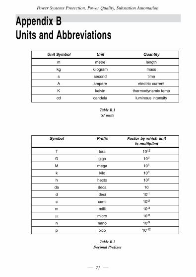
Power Systems Protection, Power Quality, Substation Automation
71
Appendix B Units and Abbreviations
Unit Symbol Unit Quantity
m metre length
kg kilogram mass
s second time
A ampere electric current
K kelvin thermodynamic temp
cd candela luminous intensity
Table B.1 SI units
Symbol Prefix Factor by which unit is multiplied
T tera 1012
G giga 109
M mega 106
k kilo 103
h hecto 102
da deca 10
d deci 10-1
c centi 10-2
m milli 10-3
µ micro 10-9
n nano 10-9
p pico 10-12
Table B.2 Decimal Prefixes
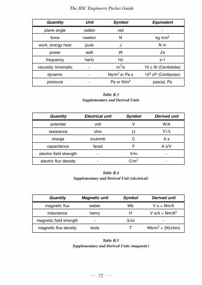
The IDC Engineers Pocket Guide
72
Quantity Unit Symbol Equivalent
plane angle radian rad -
force newton N kg m/s2
work, energy heat joule J N m
power watt W J/s
frequency hertz Hz s-1
viscosity: kinematic - m2/s 10 c St (Centistoke)
dynamic - Ns/m2 or Pa s 103 cP (Centipoise)
pressure - Pa or N/m2 pascal, Pa
Table B.3 Supplementary and Derived Units
Quantity Electrical unit Symbol Derived unit
potential volt V W/A
resistance ohm Ω V/A
charge coulomb C A s
capacitance farad F A s/V
electric field strength - V/m -
electric flux density - C/m2 -
Table B.4 Supplementary and Derived Unit (electrical)
Quantity Magnetic unit Symbol Derived unit
magnetic flux weber Wb V s = Nm/A
inductance henry H V s/A = Nm/A2
magnetic field strength - A/m -
magnetic flux density tesla T Wb/m2 = (N)/(Am)
Table B.5 Supplementary and Derived Units (magnetic)
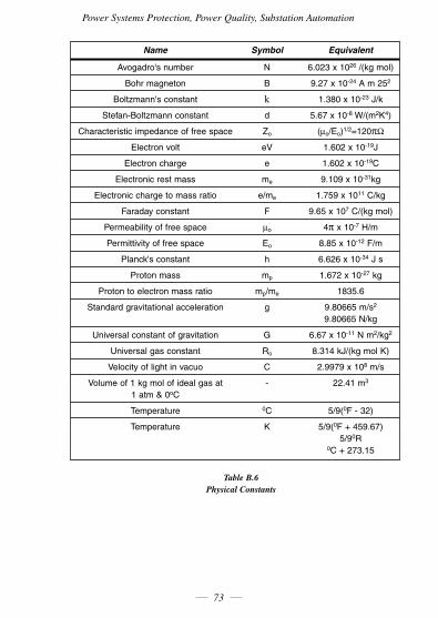
Power Systems Protection, Power Quality, Substation Automation
73
Name Symbol Equivalent
Avogadro's number N 6.023 x 1026 /(kg mol)
Bohr magneton B 9.27 x 10⁻²⁴ A m 252
Boltzmann's constant k 1.380 x 10⁻²³ J/k
Stefan-Boltzmann constant d 5.67 x 10⁻⁸ W/(m2K4)
Characteristic impedance of free space Zo (µo/Eo)1/2=120πΩ
Electron volt eV 1.602 x 10⁻¹⁹J
Electron charge e 1.602 x 10⁻¹⁹C
Electronic rest mass me 9.109 x 10⁻³¹kg
Electronic charge to mass ratio e/me 1.759 x 10¹¹ C/kg
Faraday constant F 9.65 x 10⁷ C/(kg mol)
Permeability of free space µo 4π x 10-7 H/m
Permittivity of free space Eo 8.85 x 10⁻¹² F/m
Planck's constant h 6.626 x 10⁻³⁴ J s
Proton mass mp 1.672 x 10⁻²⁷ kg
Proton to electron mass ratio mp/me 1835.6
Standard gravitational acceleration g 9.80665 m/s2 9.80665 N/kg
Universal constant of gravitation G 6.67 x 10⁻¹¹ N m2/kg2
Universal gas constant Ro 8.314 kJ/(kg mol K)
Velocity of light in vacuo C 2.9979 x 10⁸ m/s
Volume of 1 kg mol of ideal gas at - 22.41 m3
1 atm & 0oC
Temperature 0C 5/9(0F - 32)
Temperature K 5/9(0F + 459.67) 5/90R 0C + 273.15
Table B.6 Physical Constants
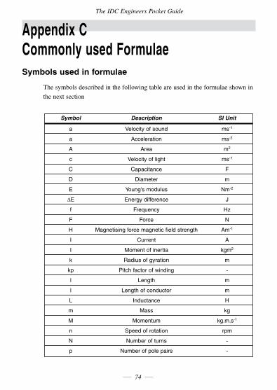
The IDC Engineers Pocket Guide
74
Appendix C Commonly used FormulaeSymbols used in formulae
The symbols described in the following table are used in the formulae shown in
thenextsection
Symbol Description SI Unit
a Velocity of sound ms-1
a Acceleration ms-2
A Area m2
c Velocity of light ms-1
C Capacitance F
D Diameter m
E Young's modulus Nm-2
∆E Energy difference J
f Frequency Hz
F Force N
H Magnetising force magnetic field strength Am-1
I Current A
I Moment of inertia kgm2
k Radius of gyration m
kp Pitch factor of winding -
l Length m
l Length of conductor m
L Inductance H
m Mass kg
M Momentum kg.m.s-1
n Speed of rotation rpm
N Number of turns -
p Number of pole pairs -
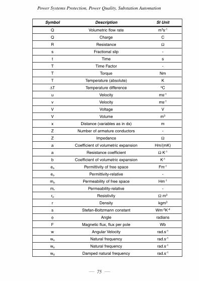
Power Systems Protection, Power Quality, Substation Automation
75
Symbol Description SI Unit
Q Volumetric flow rate m3s-1
Q Charge C
R Resistance Ω
s Fractional slip -
t Time s
T Time Factor -
T Torque Nm
T Temperature (absolute) K
∆T Temperature difference oC
u Velocity ms-1
v Velocity ms-1
V Voltage V
V Volume m3
x Distance (variables as in dx) m
Z Number of armature conductors -
Z Impedance Ω
a Coefficient of volumetric expansion Hm/(mK)
a Resistance coefficient Ω K-1
b Coefficient of volumetric expansion K-1
eo Permittivity of free space Fm-1
eo Permittivity-relative -
mo Permeability of free space Hm-1
mr Permeability-relative -
ro Resistivity Ω m3
r Density kgm3
s Stefan-Boltzmann constant Wm-2K-4
φ Angle radians
F Magnetic flux, flux per pole Wb
w Angular Velocity rad.s-1
wn Natural frequency rad.s-1
wo Natural frequency rad.s-1
wd Damped natural frequency rad.s-1
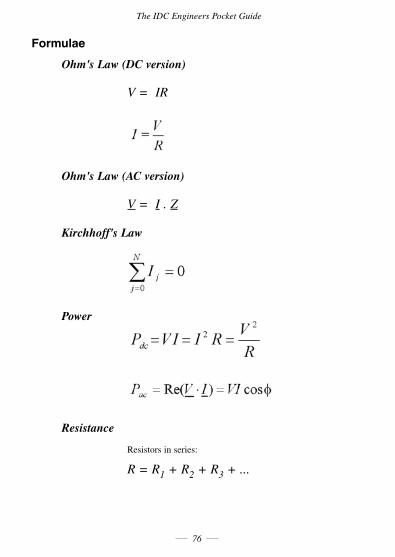
The IDC Engineers Pocket Guide
76
Formulae
Ohm's Law (DC version)
V = IR
Ohm's Law (AC version)
V = I . Z
Kirchhoff's Law
Power
Resistance
Resistors in series:
R = R1 + R2 + R3 + ...
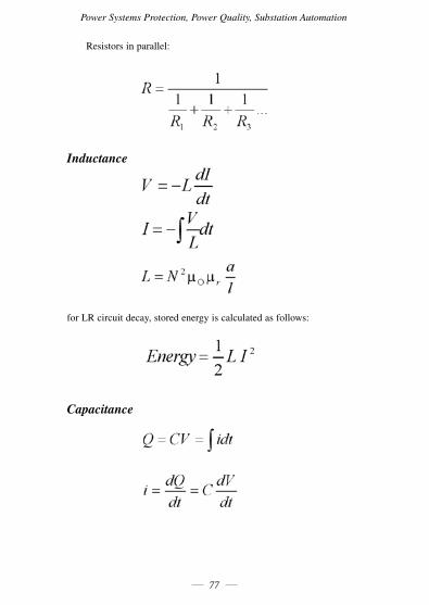
Power Systems Protection, Power Quality, Substation Automation
77
Resistors in parallel:
Inductance
for LR circuit decay, stored energy is calculated as follows:
Capacitance
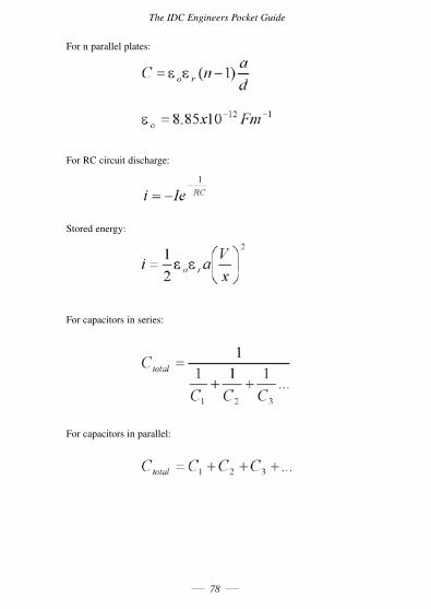
The IDC Engineers Pocket Guide
78
For n parallel plates:
For RC circuit discharge:
Stored energy:
For capacitors in series:
For capacitors in parallel:
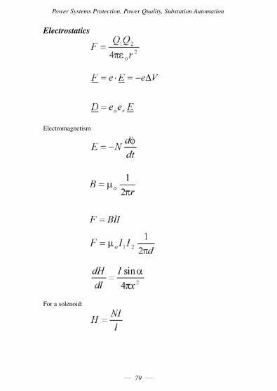
Power Systems Protection, Power Quality, Substation Automation
79
Electrostatics
Electromagnetism
For a solenoid:
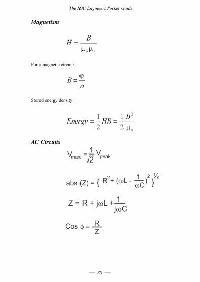
The IDC Engineers Pocket Guide
80
Magnetism
For a magnetic circuit:
Stored energy density:
AC Circuits
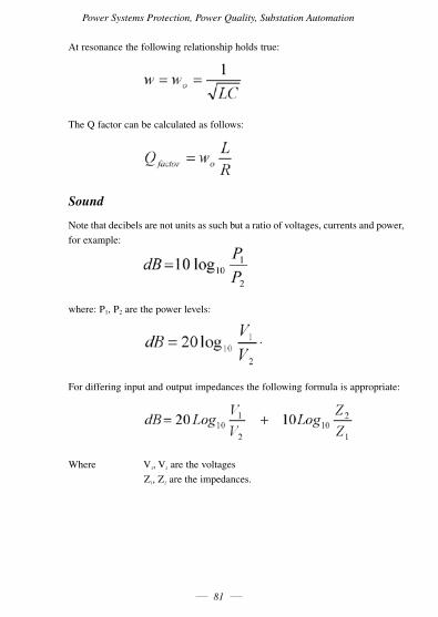
Power Systems Protection, Power Quality, Substation Automation
81
At resonance the following relationship holds true:
The Q factor can be calculated as follows:
Sound
Note that decibels are not units as such but a ratio of voltages, currents and power,
forexample:
where: P1, P2 are the power levels:
For differing input and output impedances the following formula is appropriate:
Where V1,V2 are the voltages
Z1,Z2 are the impedances.
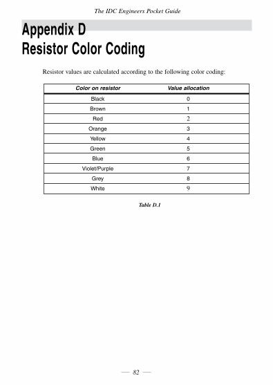
The IDC Engineers Pocket Guide
82
Appendix D Resistor Color Coding
Resistor values are calculated according to the following color coding:
Color on resistor Value allocation
Black 0
Brown 1
Red 2
Orange 3
Yellow 4
Green 5
Blue 6
Violet/Purple 7
Grey 8
White 9
Table D.1
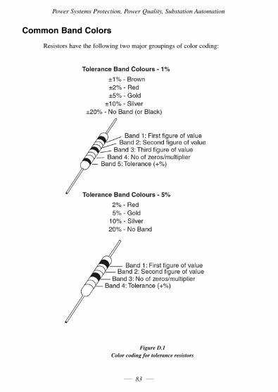
Power Systems Protection, Power Quality, Substation Automation
83
Common Band Colors
Resistors have the following two major groupings of color coding:
Figure D.1 Color coding for tolerance resistors

Who is IDC TechnologiesIDC Technologies is a specialist in the field of industrial communications,
telecommunications, automation and control and has been providing high quality
training on an international basis for more than 16 years.
IDC Technologies consists of an enthusiastic team of professional engineers and
support staff who are committed to providing the highest quality in their
consulting and training services.
The Benefits to You of Technical Training The technological world today presents tremendous challenges to engineers,
scientists and technicians in keeping up to date and taking advantage of the
latest developments in the key technology areas.
The immediate benefits of attending an IDC Technologies workshop are:
• Gainpracticalhands-onexperience
• Enhanceyourexpertiseandcredibility
• Save$$$foryourcompany
• Obtainstateoftheartknowledgeforyourcompany
• Learnnewapproachestotroubleshooting
• Improveyourfuturecareerprospects
The IDC Technologies Approach to TrainingAllworkshopshavebeencarefullystructuredtoensurethatattendeesgainmaximum
benefits. A combination of carefully designed training software, hardware and well
written documentation, together with multimedia techniques ensure that the
workshops are presented in an interesting, stimulating and logical fashion.
IDC Technologies has structured a number of workshops to cover the major areas
oftechnology.Theseworkshopsarepresentedbyinstructorswhoareexpertsin
their fields, and have been attended by thousands of engineers, technicians and
scientistsworld-wide,whohavegivenexcellentreviews.
The IDC Technologies team of professional engineers is constantly reviewing the
workshops and talking to industry leaders in these fields, thus keeping the
workshops topical and up to date.
The IDC Engineers Pocket Guide
84
Power Systems Protection, Power Quality, Substation Automation
85
Technical Training Workshops
IDC is continually developing high quality state of the art workshops aimed at assisting
engineers, technicians and scientists. Current workshops include:
DATA COMMUNICATIONS & NETWORKING• BestPracticeinIndustrialDataCommunications• PracticalDataCommunications&NetworkingforEngineersandTechnicians• PracticalDNP3,60870.5&ModernSCADACommunicationSystems• PracticalTroubleshooting&ProblemSolvingofEthernetNetworks• PracticalFieldBusandDeviceNetworksforEngineersandTechnicians• PracticalFieldbus,DeviceNetandEthernetforIndustry• PracticalUseandUnderstandingofFoundationFieldBusforEngineersandTechnicians• PracticalFibreOpticsforEngineersandTechnicians• PracticalIndustrialCommunicationProtocols• PracticalTroubleshooting&ProblemSolvingofIndustrialDataCommunications• PracticalTroubleshooting,Design&SelectionofIndustrialFibreOpticSystemsforIndustry• PracticalIndustrialNetworkingforEngineers&Technicians• PracticalIndustrialEthernet&TCP/IPNetworks• PracticalLocalAreaNetworksforEngineersandTechnicians• PracticalRouters&Switches(includingTCP/IPandEthernet)forEngineers&Technicians• PracticalTCP/IPandEthernetNetworkingforIndustry• PracticalFundamentalsofTelecommunicationsandWirelessCommunications• PracticalRadio&TelemetrySystemsforIndustry• PracticalTCP/IPTroubleshooting&ProblemSolvingforIndustry• PracticalTroubleshootingofTCP/IPNetworks• PracticalFundamentalsofVoiceoverIP(VOIP)forEngineersandTechnicians• WirelessNetworkingandRadioTelemetrySystemsforIndustry• WirelessNetworkingTechnologiesforIndustry
ELECTRICAL• PracticalMaintenance&TroubleshootingofBatteryPowerSupplies• PracticalElectricalNetworkAutomation&CommunicationSystems• SafeOperation&MaintenanceofCircuitBreakersandSwitchgear• Troubleshooting,Maintenance&ProtectionofACElectricalMotorsandDrives• PracticalTroubleshootingofElectricalEquipmentandControlCircuits• PracticalEarthing,Bonding,Lightning&SurgeProtection• PracticalDistribution&SubstationAutomationforElectricalPowerSystems• PracticalSolutionstoHarmonicsinPowerDistribution• PracticalHighVoltageSafetyOperatingProceduresforEngineersandTechnicians
The IDC Engineers Pocket Guide
86
• PracticalElectricalWiringStandards-NationalRulesforElectricalInstallations-• Lightning,SurgeProtectionandEarthingofElectrical&ElectronicSystems• PracticalPowerDistribution• PracticalPowerQuality:Problems&Solutions
ELECTRONICS• PracticalDigitalSignalProcessingSystemsforEngineersandTechnicians• PracticalEmbeddedControllers:TroubleshootingandDesign• PracticalEMCandEMIControlforEngineersandTechnicians• PracticalIndustrialElectronicsforEngineersandTechnicians• PracticalImageProcessingandApplications• PowerElectronicsandVariableSpeedDrives:Troubleshooting&Maintenance• PracticalShielding,EMC/EMI,NoiseReduction,EarthingandCircuitBoardLayout
INFORMATION TECHNOLOGY• PracticalWeb-SiteDevelopment&E-CommerceSystemsforIndustry• IndustrialNetworkSecurityforSCADA,Automation,ProcessControl&PLCSystems• SNMPNetworkManagement:TheEssentials• VisualBasicProgrammingforIndustrialAutomation,ProcessControl&SCADASystems
INSTRUMENTATION, AUTOMATION & PROCESS CONTROL• PracticalAnalyticalInstrumentationinOn-LineApplications• PracticalAlarmSystemsManagementforEngineersandTechnicians• PracticalProgrammableLogicController's(PLCs)forAutomationandProcessControl• PracticalBatchManagement&Control(IncludingS88)forIndustry• PracticalBoilerControlandInstrumentationforEngineersandTechnicians• PracticalProgrammingforIndustrialControl-using(IEC1131-3andOPC)• PracticalDistributedControlSystems(DCS)forEngineers&Technicians• PracticalDataAcquisitionusingPersonalComputersandStandaloneSystems• BestPracticeinProcess,Electrical&InstrumentationDrawingsandDocumentation• PracticalTroubleshootingofDataAcquisition&SCADASystems• PracticalIndustrialFlowMeasurementforEngineersandTechnicians• PracticalHazops,TripsandAlarms• PracticalHazardousAreasforEngineersandTechnicians• APracticalMiniMBAinInstrumentationandAutomation• PracticalInstrumentationforAutomationandProcessControl• PracticalIntrinsicSafetyforEngineersandTechnicians• PracticalTuningofIndustrialControlLoops• PracticalMotionControlforEngineersandTechnicians• PracticalSCADAandAutomationforManagers,SalesandAdmininistration• PracticalAutomation,SCADAandCommunicationSystems:APrimerforManagers
Power Systems Protection, Power Quality, Substation Automation
87
• PracticalFundamentalsofOPC(OLEforProcessControl)• PracticalProcessControlforEngineersandTechnicians• PracticalProcessControl&TuningofIndustrialControlLoops• PracticalIndustrialProgrammingusing61131-3forPLCs• PracticalSCADA&TelemetrySystemsforIndustry• PracticalShutdown&TurnaroundManagementforEngineersandManagers• PracticalSafetyInstrumentationandShut-downSystemsforIndustry• PracticalFundamentalsofE-Manufacturing,MESandSupplyChainManagement• PracticalSafetyInstrumentation&EmergencyShutdownSystemsforProcessIndustries• ControlValveSizing,SelectionandMaintenance
MECHANICAL ENGINEERING• PracticalFundamentalsofHeating,Ventilation&Airconditioning(HVAC)• PracticalBoilerPlantOperationandManagementforEngineersandTechnicians• PracticalBulkMaterialsHandling(Conveyors,Bins,Hoppers&Feeders)• PracticalPumpsandCompressors:Control,Operation,Maintenance&Troubleshooting• PracticalCleanroomTechnologyandFacilitiesforEngineersandTechnicians• GasTurbines:Troubleshooting,Maintenance&Inspection• PracticalHydraulicSystems:OperationandTroubleshooting• PracticalLubricationEngineeringforEngineersandTechnicians• PracticalSafeLiftingPracticeandMaintenance• PracticalMechanicalDrives(Belts,Chainsetc)forEngineers&Technicians• FundamentalsofMechanicalEngineering• PracticalPneumatics:OperationsandTroubleshootingforEngineers&Technicians• PracticalCentrifugalPumps-OptimisingPerformance• PracticalMachineryandAutomationSafetyforIndustry• PracticalMachineryVibrationAnalysisandPredictiveMaintenance
PROJECT & FINANCIAL MANAGEMENT• PracticalFinancialFundamentalsandProjectInvestmentDecisionMaking• HowtoManageConsultants• MarketingforEngineersandTechnicalPersonnel• PracticalProjectManagementforEngineersandTechnicians• PracticalSpecificationandTechnicalWritingforEngineers
CHEMICAL ENGINEERING• PracticalFundamentalsofChemicalEngineering
CIVIL ENGINEERING• HazardousWasteManagementandPollutionPrevention• StructuralDesignfornon-structuralEngineers• BestPracticeinSewageandEffluentTreatmentTechnologies
The IDC Engineers Pocket Guide
88
Comprehensive Training Materials
Workshop Documentation
All IDC Technologies workshops are fully documented with complete reference
materials including comprehensive manuals and practical reference guides.
Software
Relevant software is supplied with most workshops. The software consists of
demonstration programs which illustrate the basic theory as well as the more
difficult concepts of the workshop.
Hands-On Approach to Training
IDC Technologies engineers have developed the workshops based on the practical
consulting expertise that has been built up over the years in various specialist
areas.Theobjectiveoftrainingtodayistogainknowledgeandexperienceinthe
latest developments in technology through cost effective methods.
The investment in training made by companies and individuals is growing each
year as the need to keep topical and up to date in the industry which they are
operating is recognized. As a result, IDC Technologies instructors place particular
emphasisonthepractical,hands-onaspectoftheworkshopspresented.
On-site Workshops
In addition to the external workshops which IDC Technologies presents on a
world-widebasis,allIDCTechnologiesworkshopsarealsoavailableforon-site
(in-house)presentationatourclientspremises.
On-sitetrainingisacosteffectivemethodoftrainingforcompanieswithmany
delegates to train in aparticular area.Organizations can savevaluable training
$$$ by holding workshops on-site, where costs are significantly less. Other
benefits are IDC Technologies ability to focus on particular systems and
equipment so that attendees obtain only the greatest benefits from the training.

Power Systems Protection, Power Quality, Substation Automation
89
Allon-siteworkshopsaretailoredtomeetwithclientstrainingrequirementsand
workshops can be presented at beginners, intermediate or advanced levels based
on the knowledge and experience of delegates in attendance. Specific areas of
interest to the client can also be covered in more detail.
Ourexternalworkshopsareplannedwellinadvanceandyoushouldcontactusas
earlyaspossibleifyourequireon-site/customizedtraining.Whilewewillalways
endeavor to meet your timetable preferences, two to three months notice is
preferable in order to successfully fulfil your requirements.
Please don’t hesitate to contact us if you would like to discuss your training
needs.
Customized Training
In addition to standard on-site training, IDC Technologies specializes in
customized workshops to meet client training specifications. IDC Technologies
has the necessary engineering and training expertise and resources to work
closely with clients in preparing and presenting specialized workshops.
These workshops may comprise a combination of all IDC Technologies
workshops along with additional topics and subjects that are required. The
benefits to companies in using training is reflected in the increased efficiency of
their operations and equipment.
Training Contracts
IDC Technologies also specializes in establishing training contracts with
companies who require ongoing training for their employees. These contracts can
be established over a given period of time and special fees are negotiated with
clients based on their requirements. Where possible IDC Technologies will also
adapt workshops to satisfy your training budget.
References from various international companies to whom IDC Technologies is
contracted to provide on-going technical training are available on request.

The IDC Engineers Pocket Guide
90
Some of the thousands of Companies world-wide that
have supported and benefited from IDC Technologies
workshops are:AustraliaAlcoa•AlintaGas•AmpolRefineries•Ansto•AustralianCommunicationsAuthority•AustralianGeologicalSociety•BHPBilliton•BOCGases•BoeingConstructorsInc•BrisbaneCityCouncil•BritishAerospaceAustralia•CiTechnologies•CivilAviationAuthority•ComalcoAluminium•CSIRO•DeltaElectricity•DeptofDefence•Deptof Transport and Works • DSTO • Duke Energy International • Emerson ProcessManagement•Energex•ERGGroup•ErgonEnergy•ETSA•GippslandWater•GladstoneTafeCollege•GosfordCityCouncil•GreatSouthernEnergy•HamersleyIron•HewlettPackard•HoldenLtd•Honeywell•I&ESystemsPtyLtd•IntegralEnergy•MetroBrick•MilleniumChemicals•MtIsaMines•MurdochUniversity•Nabalco • NEC • Nilson Electric • Normandy Gold • Nu-Lec Industries • ParkerHannafin•Pharmacia&Upjohn•Power&WaterAuthorityNT•Powercor•Powerlink•ProspectElectricity•QueenslandAlumina•Raaf•Raytheon•RGCMineralSands•RobeRiverIronAssociates•RoyalDarwinHospital•SantosLtd•SchneiderElectric•Shell•SnowyMountainHydro•SPCFruit•StanwellPowerStation•Telstra•Tiwest• Uncle Bens •Vision • Wesfarmers CSBP • Western Power • Westrail • WMC •Woodside•WorsleyAlumina•WyongShire•YokogawaAustralia
BotswanaDeBeers-JwanengMine•DeBeers-OrapaMine
CanadaAircomIndustries(76)Ltd•AtcoElectric•BCGas•BCHydro•CityofOttawa•CityofSaskatoon•Conoco•DeptofNationalDefence•EnbridgePipelines•Enmax•FordElectronics•GEEnergyServices•GeneralMotors•GuillevinAutomation•HuskyOil•ImperialOil•INCOLtd•LabradorHydro•ManitobaHydro•ManitobaLotteriesCorp•MemorialUniversityofNewFoundland•NewBrunswickPower•NovaChemicals • NxtphaseCorporation•OntarioHydro•OttawaHydro•PetroCanada•PowerMeasurementLtd•SaskatchewanPower•SpartanControls•Stora•SuncorEnergy•Syncrude•Telus•TransCanadaPipelines•TrojanTechnologies•WascanaEnergy•Weyerhauser
IrelandBayerDiagnostics•ESBDistribution•Intel•IrishCement•JannsenPharmaceuticals•MicrosolLimited•Pfizer•PilzIreland•ProsconEngineering
NambiaNamibianBroadcastingCorporation•Nampower•Namwater

Power Systems Protection, Power Quality, Substation Automation
91
New ZealandACI Packaging • Anchor Products • Auckland Regional Council • Ballance AgriNutrients•ContactEnergy•Ericcson•Fisher&Paykel•GECAlsthom•JamesHardie •Methanex•NaturalGas•NZWaterandWasteAssoc•NorskeSkog•NZAluminiumSmelters•NZRefiningCo•PanPacForestProducts•Powerco•Rockwell•RotoruaDistrictCouncil•RoyalNewZealandNavy•TheUniversityofAuckland
SingaporeActivemediaInnovationPteLtd•FlotechControls•LandTransportAuthority•NgeeAnnPolytechnic•PowerSerayaLtd•Westinghouse•YokogawaSingapore
South AfricaAngloAmerican•BatemanMetals•CaltexRefineries•Chevron•ColumbusStainless•DeBeers•DurbanMetro•EasternCapeTech•Eskom•GrintekEwation•HighveldSteel•IllovoSugar•ImpalaPlatinums•Iscor•IST•JoyMining•LeverPonds•MetsoAutomation•MiddleburgFerrochrome•Mintek•MondiKraft•Mossgas•NamaquaSands•Nestle•Orbicom•RandWaterBoard•RichardsBayMinerals•SANavy•SABC•SaldanhaSteel•Sappi•Sasol•Spoornet•UmgeniWater•WesternPlatinum•WitwatersrandTechnikon•YellandControls
United Kingdom24Seven•ABBAutomationLtd•AerRianta•AirProducts•AlliedColloids•AlliedDistillers •Alstom • BAE Systems • Bechtel • BNFL - Magnox Generation • BPChemicals•BritishAmericanTobacco•BritishEnergy•BritishGas•BritishSteel•Cegelec•Conoco•CorusGroupPlc•EnergyLogistics•Eurotherm•Eurotunnel•EveshamMicros•ExultLtd•FisherRosemount•GECMeters•GlaxoSmithKline•GlaxoWellcome•GreatYarmouthPower•Halliburton•Honeywell • ICINobelEnterprises•ICSTriplex•InmarsatLtd•InstemLimited•JohnsonMatthey•Kodak•KvaernerEnergy•LeverFabrige•LindsayOilRefinery•Lloyds•Logica•LucasAerospace•MobilOil•NEC•Nissan•NorthernLighthouseBoard•OKIEuropeLtd•PhillipsPetroleum•Powergen•Qinetiq•RailTrackSystems•RigTech•Roberts&Partners•RollsRoyce•RoverGroup•RugbyCement•ScottishCourage•ScottishHydroElectricPlc•ScottishPower•ShellChemicals•ShottonPaperPlc•Siemens•StrathclydeWater•ThamesWater•Toyota•Transco•TrendControlSystemsLtd•UKAEA•UnitedKingdomPaper•YarrowShipbuilders•YorkshireElectric
USAAlcatel •AllenBradley•AstraZenecaPharmaceuticals •AvistaCorporation•Boeing•Chevron•CityofDetroit•DaishowaPaperMill•DegussaCorporation•DeptofEnergy•DetroitWater•ExxonMobilChemicalCompany•FMCCorporation•GeneralMonitors•Honeywell•HughesAircraft•ISA•K-TronInstitute•MckeeFoods•Milltronics•NASA•PepperlFuchs•PhelpsDodge•PhilipMorris•SanDiegoCountyWaterAuthority•SanFranciscoWaterDepartment•SantaClaraValleyWater•SecuritiesIndustryAutomationCorp • Siemens Power • Siemens Westinghouse • Toyota • Tucson Electric • UnitedTechnologiesCorp(UTC)•Valtek•WashingtonWaterPower•WisconsinPower•Zeneca

The IDC Engineers Pocket Guide
92
IDC Technologies - Worldwide Offices
For further information about current or future workshops please contact your
local office:
Australia
POBox1093,WestPerthWA6872
Tel:(08)93211702 Fax:(08)93212891
Canada
402-814RichardsStreet,VancouverBCV6B3A7
Tel:18003244244 Fax:18004344045
Ireland
Caoran,BailenahAbhannCoGalway
Tel:(01)4733190 Fax:(01)4733191
Malaysia
26JalanKotaRajaE27/E,HicomTownCenter,
Seksyen 27, 40400 Shah Alam, Selangor
Tel:(03)51923800 Fax:(03)51923801
New Zealand
POBox76142,ManukauCity2241Auckland
Tel:(09)2634759 Fax:(09)2622304

Power Systems Protection, Power Quality, Substation Automation
93
Singapore
100EuTongSenStreet,#04-11Pearl'sCentre,059812
Tel:(65)62246298 Fax:(65)62247922
South Africa
68PretoriusStreet,PresidentPark,Midrand
POBox389,HalfwayHouse1685
Tel:0110245520/1/2/3/4/5 Fax:(086)6924368
UK
Suite 18, Fitzroy House, Lynwood Drive,
WorcesterPark,SurreyKT47AT
Tel:(020)83354014 Fax:(020)83354120
USA
10685-BHazelhurstDrive#6175,HoustonTX77043
TollFreeTel:18003244244 TollFreeFax:18004344045
Email: [email protected] site: www.idc-online.com

NotesThe IDC Engineers Pocket Guide
94