the ilsp behavioral description language and its …
TRANSCRIPT
THE ILSP BEHAVIORAL DESCRIPTION LANGUAGEAND ITS GRAPH REPRESENTATIONFOR BEHAVIORAL SYNTHESIS
Masayasu OdaniSun Young HwangTom BlankTom Rokicki
Technical Report: CSL-TR-88-350
March 1988
This work was supported by Defense Advanced Research Projects Agencyunder Contract No. MDA 903-83-C-0335, and partly by Toshiba Corporation.
THE ILSP BEHAVIORAL DESCRIPTION LANGUAGEAND ITS GRAPH REPRESENTATION
FOR BEHAVIORAL SYNTHESIS
Masayasu Odani, Sun Young Hwang, Tom Blank, and Tom Rokicki
Technical Report: CSL-TR-88-350
March 1988
Computer Systems LaboratoryDepartments of Electrical Engineering and Computer Science
Stanford UniversityStanford, CA 943054055
Abstract
This report describes the ILSP behavioral description language and its internalrepresentation employed in the Hemod behavioral synthesis system. Using combinedcontrol/data flow graph (C/DFG) as an intermediate representation, Hermod generateshardware modules and their interconnection from behavioral descriptions. Hex-mod isincluded in an integrated environment for hardware simulation and synthesis systemunder development at Stanford University. The functional models written in ILSP canbe simulated on the THOR logic/functional/behavioral simulator without translation.After proper verification of its behavior, an ILSP model can be input to the synthesizerfor compilation into an RT-level description.
This report consists of two parts: the specification of the ILSP language and its graphrepresentation.
Key Words and Phrases: behavioral description language, behavioral synthesis,structural synthesis, control and data flow graph, register-transfer level description,functional simulation.

Copyright 0 1988
bY
Masayasu OdaniSun Young Hwang
Tom BlankTom Rokicki
The ILSP Behavioral Description Language
1. OverviewThis document provides the features and syntax of the ILSP(Input Language for
Synthesis Program), which is used to describe the behavior of functional modules.Compared to the ISPS (Instruction Set Processor Specifications) which describeshardware at register-transfer level, the ILSP description is purely procedural orbehavioral. Her-mod is included in an integrated environment for hardware simulationand synthesis system under development at Stanford University. The functional modelswritten in ILSP can be simulated on the THOR logic/functional/behavioral simulatorwithout translation. After proper verification of its behavior, an ILSP model can bepipelined to the synthesizer for compilation into an RTL-level description.
Based on the C-language, ILSP has conditional (if-then-else and switch), and loop(while- and do-loop) control constructs. It also allows explicit specification of theactual hardware interface to the outside world. Many features of the C languageconsidered redundant or unnecessary for behavioral representation of a hardwaremodule are omitted in ILSP. For instance, only integer type variables are supported,and parameter passing is handled through interface declarations in the ILSP proceduredeclaration section.
. .
The overall features of ILSP are presented in the first three*sections, followed by theILSP syntax. The differences from the C language are presented in each section.

2. Lexical ConventionsThere are five classes of tokens: identifiers, keywords, constants, operations, and
delimiters (like ‘(’ or ’ (‘). Blanks, tabs, newlines, and comments are used to separatetokens.
2.1 CommentsThe characters ‘/*’ introduce a comment, which ends with the characters ‘*/‘.
2.2 IdentifiersAn identifier consists of a sequence of letters and digits. The identifier must start
with a letter. The underscore ‘-’ counts as a letter. Upper and lower case letters areconsidered different. There are no restrictions on the length of the identifier.
2.3 Keywords - Reserved WordsThe following identifiers are reserved for use as keywords. The keyword extern is
not supported for global variables in IMP; instead, they should be explicitly declared inthe interface declaration sections.
int GRPr?gIsT OUTJ4L!5Tif elsedefault breakONE ZEROMODEL return
2.4 Constants
. .
SIG BUSSTLISTm&hdoFLOATL.S!O
ENDLJSTcasewhileUNDEFMSBO
There are two types of constants: integer constants and reserved constants. Aninteger constant consists of a sequence of digits. Only decimal expressions are allowed.
The reserved constants are ONE, ZERO, FLOAT, and UNDEF. They are irszd torepresent the value of a signal line in the THOR simulation system. The objectsdeclared as SIG or GRP in the interface declaration sections are allowed to have one ofthese values.

3. Attributes of an ObjectILSP supports three fundamental types of objects. The objects declared as integers
(int) are local variables to the procedure in which they are declared. The objectsdeclared as signals (SIG) are one-bit-signal variables and those declared as groups (GRPor BUS) are multiple-bit-signal variables. The bit width and bit order are specified forGRP-type objects (LSBO - lowest indexed bit is the least significant bit or MSBO -lowest indexed bit is the most significant bit).
The SIG- and GRP-type objects have one of three types of io-attributes: input,output, and state. The value of the input variable (declared in IN-LIST section) istaken from the outside of the procedure, and that of the output variable (declared inOUT-LIST section) is brought to the outside of the procedure. The state variables(declared in ST LIST section) correspond to the static integers of a C procedure. They-are local to the procedure, but retain their values upon reentry to the procedure evenafter the control leaves from the procedure.
The SIG- and GRP-type objects are the abstract representations of registers in thehardware representation. An integer object may be realized by a register in thehardware, or just as a wire for signal flow depending on its usage and lifetime.
4. Behavioral ModelBehavioral models consist of a procedure declaration section and a procedural body.
The constructs are almost the same as in the C language. The differences are:
1. The parameter passing mechanism in a procedure call is handled throughthe interface mechanism supported in ILSP. That is, the input and outputparameters are declared in the interface declaration sections (IN-LISTand OUT-LIST declarations) unlike C procedures.
2. A return statement is allowed only at the end of a procedure. Noexpressions are allowed after a return statement. Instead, a procedure canreturn values by assigning values to the variables declared in theOUT-LIST section.
The syntax for a behavioral model or procedure is presented as follows:

model:procedure-declaration procedure-body
,
procedure-declaration:procedure-identifier ‘(’ ‘)’
I MODEL ‘(’ procedure-identifier ‘)’.,
procedure-identifier:identifier
procedure-body:’ ( ’ declaration statement-list return ‘;’ ’ ) ’
5. DeclarationsIdentifier declarations specify their attributes including the interface signals to the
outside of the procedure, the state and local variables. For a group of signals, if the bitorder is not specified, the signal with the lowest index is considered as the leastsignificant bit (LSBO).
declaration:signal-declaration integer-declaration.9
signal-declaration:input-declaration output-declaration state-declaration
.
input-declaration:IN-LIST signal-list ENDLIST ‘;’
output-declaration:OUT-LIST signal-list ENDLIST ‘;’
state-declaration:I* empty *I
I ST-LIST signal-list ENDLIST ‘;’
4

i
signal-list:signal-list signal
I signal
signal:SIG ‘(’ identifier ‘)’ ‘;’
I GRP ‘(’ group-signal-identifier ‘,’ bit-width bit-order ‘1’ ‘;’
group-signal-identifier:idenhper
,
bit- width:constant
bit-order:I* empty *I
I ‘,’ LSBOI ‘,’ MSBO
integer-declaration:P empty *I
I int identifier-list ‘;’;
* idenh_fier-list: .identifier
I identifier-list ‘,’ identifier
6. StatementsMost statements in the C language are supported except that
1. ILSP allows procedure calls that return more than one value.“(receiver-list) = procedure-call-expression;” form is used for procedurecalls that return multiple outputs and distributes the values to the variablesand group signals in the receiver-list.
2. A break statement is allowed only in a switch statement to eliminateabrupt loop exits.
5

statement-list:statement -
I statement-list statement
statement:’ ( ’ statement-list ’ ) ’
I assignment ‘;’I if ‘(’ expression ‘)’ statementI if ‘(’ expression ‘)’ statement else statementI while ‘(’ expression ‘)’ statementI do statement while ‘(’ expression ‘)’ ‘;’I switch ‘(’ expression ‘)’ ’ ( ’ case-statement-list default-statement ’ ) ’
assignment:increment-expression
I receiver ‘=’ expressionI ‘(’ receiver-list ‘)’ ‘=’ procedure-call-expression
receiver-list: - *receiver
I receiver-list ‘,’ receiver.9
receiver:identifier
I group-signal-identifier ’ [’ range ‘3 ’.9 .
case-statement-list:case-statement
I case-statement-list case-statement
case-statement:cze constant ‘:’
I case constant ‘:’ break ‘;’I case constant ‘1’ statement-list break ‘;’
default-statement:default ‘:’ break ‘;’
I default ‘:’ statement-list break ‘;’.9

7. ExpressionsExpressions used in ILSP are again based on the C language. General data structures
including pointers and arrays are not allowed. Array structure is allowed only torepresent a group of signals. The differences from the C language in expressions aresummarized as follows:
1. ILSP does not allow integer arrays, structures, or pointers. An exceptionis that a pointer is passed to a subprocedure as an argument for a GRP-type object in a procedure call.
2. ILSP uses the array structures for group signals to specify bit position. AGRP-type object followed by a range in square brackets specifies aportion of group signals. The expression x[] implies the entire signalgroup of x will be treated as an integer. The expression x[3] represents thesignal value of the third bit of x, and x[7:4] means that the partial signalgroup between the seventh bit and fourth bit of x is treated as an integer.
3. ILSP allows increment expressions (++ and --) for integer variables only.
expression:primary-expression
I mar-y-expressionI increment-expression1 binary-expression.9
7.1 Primary Expressions
primary-expression:identifier
I constantI reserved-constantI group-signal-identifier ‘[’ range ‘1’I ‘(’ expression ‘1’I procedure-call-expression
procedure-call-expression:procedure-identifier ‘(’ expression-list ‘1’.9
expression- list:expression
I expression-list ‘,’ expression
7
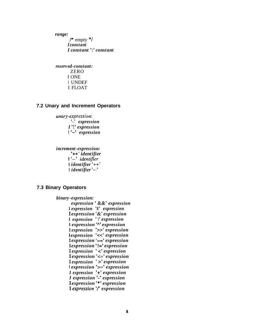
range:/* empty */
I constantI constant ‘:’ constant
reserved-constant:ZERO
I ONE1 UNDEFI FLOAT
7.2 Unary and Increment Operators
unary-expression:’ - ’ expression
I ‘!’ expression1 ‘-’ expression
increment-expression:‘++’ identifier
1 9- i&n tifierI identifier 9-4I identifier ‘--’
7.3 Binary Operators
binary-expression:expression ’ &&’ expression
I expression ’ II ’ expressionI expression ‘&’ expressionI expression ’ I’ expressionI expression ‘I\’ expressionI expression 59 expressionI expression ‘Cc’ expressionI expression ‘=’ expressionI expression ’ !=’ expressionI expression ’ 4 expressionI expression k=’ expressionI expression ’ 9 expression1 expression ‘>=’ expressionI expression ‘4 expressionI expression ‘-’ expressionI expression ‘*’ expressionI qression ‘f expression
8

I expression ‘70’ expression
8. ExamplesThe following ILSP procedure describes the functional module that takes two input
groups of signals, in and enable, and calculates the factorial of the value of in, settingthe signal group out and the signal line valid.
IN-LISTSIG( enable );GRP( in, 8 );
ENDLIST;
/* declare input ports */
OUT-LISTSIG( valid );GRP( out, 16 );
ENDLIST;
/* declare output ports */
int r, s; /* declare local variables */
valid = 0;if ( enable ) {
r = inn;s = 0;while (r >= 0) {
S = s + r ;r --
1 ’
out[] = s;valid = 1;
return;
/* set the flag */
The objects declared in the IN-LIST section represent input signals or ports fromexternal. The object enable represents one signal line, and in represents a group ofsignals consisting of 8 signal lines. Likewise the objects in the OUT-LIST section

represent output signals or ports set by the procedure. The statement “r = in,” meansthat the signals grouped as in are packed into an integer (I-). The statement “out[] = s”sets the group of output signals, out, by unpacking the integer (s).
Another example is given below. This procedure describes an ILSP functional modelthat takes two integers and produces the greatest common divisor (GCD) of those twointegers. The procedure swap0 swaps two integers.
WK)1
IN-LISTSIG( enable );GRP( a, 16);GRI’( b, 16 );
ENDLIST,
OUT-LISTSIG( valid );GRP( out, 16 );
ENDLIST;
int aa, bb;
valid=O;if (enable) {
aa=afl;bb = b[] ;while ( aa != bb ) {
while ( bb > aa )bb=bb-aa;
( aa, bb ) = swap{ aa, bb );1
out[] = aa;valid = 1;
1return;
1
10

Graph Representation of ILSP Procedures
1. OverviewIn the behavioral synthesis process, a behavioral representation is translated into an
intermediate representation in graph form, which is subsequently transformed andtranslated into a structural description 141. In Her-mod, a graph representation is chosenthat reflects both the program sequencing and the data flow in the program (Control andData Flow Graph). One of the advantages of combining those two aspects is that datadependencies that cannot be established in data flow analysis can be inferred by thecontrol sequencing in the graph 131.
Data and control operations are represented as nodes in the graph. Data and controltransfers between nodes are represented by arcs. This document describes thespecification of the control and data flow graph (C/DFG) which is produced by parsingthe ILSP program. The C/DFG consists of several data flow subgraphs correspondingto basic blocks of the original ILSP program, each of which consists of straight linecode and control nodes connecting them. The graph shows not only the dependency orparallelism of each operation but also the global control and data flow. It also providesa design representation capable of supporting design analyses, design decisions, anddesign transformations.
Her-mod supports a menu-driven user interface, displaying the control and data flowgraph on the workstation screen and allowing the user to control state binding andresource sharing through a graphical interface. The C/DFG also allows hierarchicaldesign by incorporating a procedure-call node. A procedure-call node representingsome functional module can be specified by another graph.
In this document, wc present the C/DFG as an intermediate representation of theILSP program, and describe the C/DFG construction. Examples are provided.
11

2. C/DFG StructureThe C/DFG consists of several types of nodes and edges. A node can represent data,
an abstract operation (a logical or arithmetic operation or a procedure call), and acontrol construct. An edge can be a control edge representing control sequencing in theILSP procedure, or a data edge representing data usage or data flow, depending on thetype of the nodes connected by it. In this section, types and attributes of the node andedge are described.
2.1 Nodes of C/DFGThere are five types of nodes: data, constant, operation, control, and temporary
nodes. Each node has one or more input ports and output ports to which in-coming andout-going edges are connected. Each port is identified by its io-attribute and port-id.Data, constant, temporary, and operation nodes (together with directed edges into andout of the nodes) reflect the data flow and data dependency, while control nodes areused for control sequencing and to mark the boundary of basic blocks.
2.1 .I Data/Constant/Temporary NodesA data (or constant) node corresponds to an identifier (or constant) in the ILSP
program. Basically, for each appearance of an identifier in the ILSP program, there is adata node in the graph corresponding to the identifier. Temporary nodes are used torepresent the data produced by an operation and used by another operation or controlnode. Each of these nodes has one input port and one output port Data and constantnodes are graphically represented by circles with their symbolic names inside.Temporary nodes are represented by filled circles.
2.1.2 Operation NodesAn operation node corresponds to an abstract operation in the ILSP program. A
procedure call is considered an operation with multiple inputs and outputs. There arethree types of operation nodes: binary operation, unary operation, and procedure callnodes. Figure 1 shows the graph representations of the operation nodes of the C/DFG.
1. Binary operation nodes: A binary operation node takes two inputs andproduces one output. Binary operation nodes have two input ports,RIGHT and LEFT, and one output port. The bit width of each port can bedifferent. Table 1 shows the binary operations implemented in Her-mod.
2. Unary operation nodes: A unary operation node takes one input andproduces one output (both have port-id of 0). The input and output portshave the same bit width. Her-mod supports the following unaryoperations: “M” (one’s complement), “-” (negation), and “!” (logicalnegation).
12
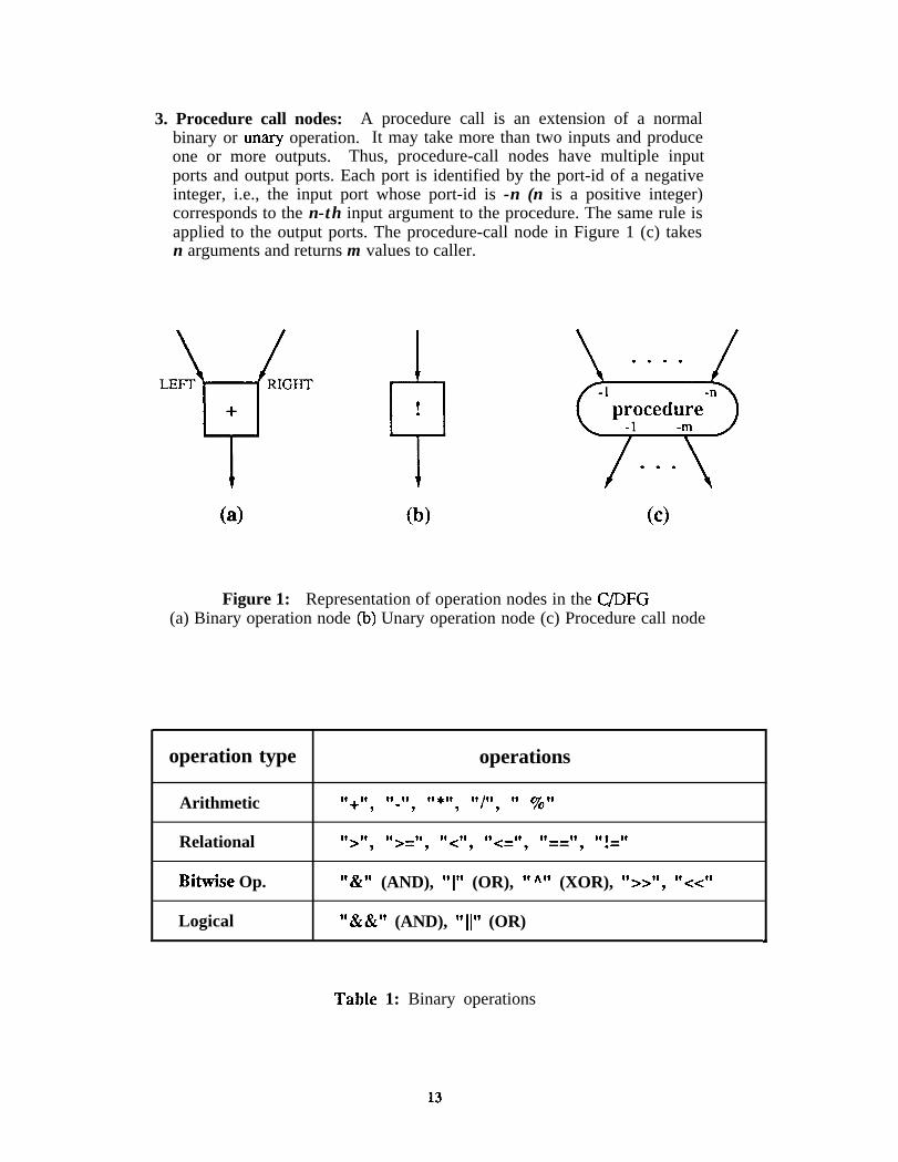
3. Procedure call nodes: A procedure call is an extension of a normalbinary or unary operation. It may take more than two inputs and produceone or more outputs. Thus, procedure-call nodes have multiple inputports and output ports. Each port is identified by the port-id of a negativeinteger, i.e., the input port whose port-id is -n (n is a positive integer)corresponds to the n-th input argument to the procedure. The same rule isapplied to the output ports. The procedure-call node in Figure 1 (c) takesn arguments and returns m values to caller.
0a 0C
Figure 1: Representation of operation nodes in the C/DFG(a) Binary operation node (b) Unary operation node (c) Procedure call node
operation type
Arithmetic
Relational
Bitwise Op.
Logical
operations
“+“, “~“, “*~‘, “/“, ‘1 yott
“>“, “>=“, “<“, t’<=“, “==“, “!=”
“W (AND), “1” (OR), “h” (XOR), “>>“, “<<”
“&&” (AND), “I[” (OR)
TabIe 1: Binary operations
13
2.1.3 Control NodesA control node marks the beginning or end point of a basic block. In other words, a
basic block starts and ends with a control node. There are seven different control nodesin ILSP, whose representations are shown in Figure 2.
1. start node: The start node represents the beginning of the whole graph,thus there should be only one start node in the graph. The start node hasno input port but has one output port. In the C/DFG, the start node hasout-going edges that go to the data nodes corresponding to constants,input signals, and state variables declared in the ILSP procedure.
2. end node: The end node represents the end of the graph, thus thereshould be only one end node at the bottom of the C/DFG. The end nodehas one input port that takes the edges from the data nodes correspondingto the output signals and the state variables that are defined but not killed(not assigned a new value) in the basic block ending with the end node.
3. fork node: A fork node is used in the if-then-else statement and marksthe beginning of the subgraph corresponding to the body of theconditional statement. The fork node has two input ports. One port takesedges from the data nodes which are used after the fork node, i.e., in thebody of the conditional statement. The other port takes an edge from thenode which produces the control data of the fork node. The fork node hastwo output ports: TRUE and FALSE ports. These ports are the beginningsof the subgraphs corresponding to then-part and else-part, respectively.
4. sfork node: A sfork node marks the beginning of a switch-statement. Ithas two input ports, whose connections are same as those of a fork node.Output ports mark the beginnings of the subgraphs representing case
. statements and default statement.
5. join node: A join node marks the end of an if-then-else or switchstatement. It has one input port and one output port. The join node alsomarks the beginning of a while-loop subgraph.
6. loop node: A foop node is used as the starting control node for thesubgraph corresponding to a do-loop construct. It has one input port andone output port. The function of the loop node is same as the join node inthe while-loop construct.
7. loop-end node: A loop-end node marks the end of the subgraphcorresponding to a do-loop construct. It has two input ports whoseconnections are same as those of fork node, and two output ports, TRUEand FALSE ports. The function of the loop-end node is almost same asthe fork node. The difference is that the FALSE port is connected to theloop node by a control edge so that the subgraph between loop node andloop-end node can be repeated.

( >a w
,/ SFORK \
0C
00ee
Figure 2: Control node representations in the C/DFG
15

2.2 Edges of C/DFG.
An edge in the graph is a-directed edge which shows the flow of data or control fromthe initial node to the terminal node. There are two types of edges: data edges andcontrol edges.
2.2.1 Data EdgesData edges show
they connect, theiredges.)
1. data node to operation node: implies the corresponding data isconsumed by the operator.
the data flow in the C/DFG. Depending on the type of the nodesimplications are different. (Figure 3 shows an example of data
2. operation node to data node: implies the result produced by theoperation is stored in the variable represented by the data node.
3. operation node to temporary node: implies the data produced by theoperation is stored temporarily for use by another operation or controlnode. This construction, for instance, is used for building the subgraphfor expressions which have more than one operation.
2.2.2 Control EdgesThe implications of control edges are different depending on what types of nodes
they connect. The usage of control edges is as follows: (An example is given in Figure4, where control edges are represented by solid arrows.)
1.
2.
3.
data or temporary node to control node: implies the value of the datanode controls the action of the control node (typically, fork, sfork andloop-end nodes).
control node to data or constant node: implies the data or constant isused in the basic block headed by the control node.
control node to control node: This type of control edges representscontrol transfer.
2.2.3 Edge AttributesJust as the node of the C/DFG has attributes, each edge of the C/DFG has attributes
independent of the edge type (DATA or CONTROL). Each edge has one of thefollowing attributes:
1. NORMAL: This means the edge is neither a BACK edge norTIMING-CUT edge. (See below.)
2. BACK: A BACK edge is an edge which constructs a loop in the C/DFG.This edge appears in a subgraph which corresponds to the while-loop or
16

the do-loop. See while-loop and do-loop constructions in the next section.
3. TIMING-CUT: A TIMING-CUT edge has timing-cuts on it. A timing-cutmeans the synchronization by a clock should be done at the cut point. Thedata going through the edge will be stored in a register. The timing-cutscreation program (automatic or manual) will choose the proper edges fortiming-cut position and makes them TIMING-CUT edges.
4. B-AND-P A B-AND-T edge is a BACK edge with timing-cut on it.
Figure 3: Example of data edges
17

1 I I
Loop Body
Figure 4: Example of control edges
18

3. GraphAn ILSP
statements,
Constructionprocedure consists of three types of blocks: straight line code, if/switchand while- and do-loops. Graph construction of each type of block is
described next.
3.1 Straight Line CodeA block of straight line code consists of expressions and assignments. The subgraph
representing straight line code is a directed acyclic graph (DAG). A typical example ispresented in Figure 5.
max
dout
x = a[] - a[] cc 2 ;y = b[] >> 1;out[] = max ( a[], x + y ) ;
Figure 5: Straight line code
19

Usually many optimization and transformation techniques employed in a complierare applied to these subgraphs in a behavioral synthesis systems. Expressions arerealized so that the operation nodes take edges from the operand data nodes.Assignment is normally realized by the edge from an operation node to a data node,which means that the result of the operation is stored in the variable represented by thedata node. Temporary data nodes are inserted if necessary. Note that temporary nodesare shown for data produced by an operation node and consumed by another operationnode. In special cases like x = a or x = 0, the assignment operator is used to show thevalue of the left side variable is replaced by that of the right hand side variable.
Retrieving data from or assigning values to a subset of group signals is allowed in theILSP syntax. To construct the subg-raph which shows such a partial retrieval orassignment, the jjmck and jimpack (intrinsic library functions in the THOR simulator[ 1,2]) procedure-call nodes are used as shown in Figure 6.
x = a[351
0a
a[351 = x
(W
Figure 6: (a) functionfpack (b) functionfunpack
3.2 Conditional StatementsThe if-then-else block consists of two sub-blocks corresponding to the then-part and
else-part, respectively. The then-part (else-part) sub-block starts from the TRUE(FALSE) port of a fork node and ends at a join node. The out-going control edges ofeach port of the fork node show that the terminal nodes of those edges (data nodes orconstant nodes) will be used in then-part sub-block or else-part sub-block. The in-coming edges of the join node show that the corresponding data nodes were defined but
20

not killed in either sub-block. The subgraph corresponding to the conditionalexpression of the if statement is inserted in the basic block which ends at the join node.The fork node takes several in-coming edges whose initial nodes were defined in thebasic block but not killed. An example is illustrated in Figure 7.
++ss
SS SS
@@JOINJOIN
..
..
Figure 7:Figure 7:
if ( a[] == 0 )s[] = s[] + 1 ;
else~11 = Ml ;
If-then-else construction
21

A switch statement is converted into a block which has several sub-blocks. Each ofthese sub-blocks corresponds to a case statement or the defuuh statement of the originalswitch statement. The sub-block corresponding to the n-th case (or default) statementof the switch statement starts from the n-th port (or DEFAULT) port of a sfork node andends at a join node. The meaning of in-coming and out-going edges of the sfork nodeand the join node is the same as in the if-then-else block. Figure 8 shows the graphconstruct of a switch statement.
switch ( a[] ) {case0:
s[] = 0 ;break ;
easel:s[] = s[] + 1 ;break ;
default :s[] = s[] - 1 ;
b r e a k ;
Figure 8: Switch construction
22
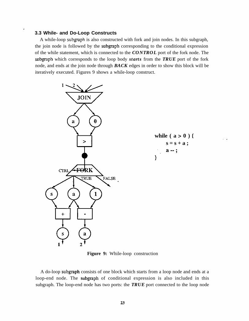
3.3 While- and Do-Loop ConstructsA while-loop subgraph is also constructed with fork and join nodes. In this subgraph,
the join node is followed by the subgraph corresponding to the conditional expressionof the while statement, which is connected to the CONTROL port of the fork node. Thesubgraph which corresponds to the loop body starts from the TRUE port of the forknode, and ends at the join node through BACK edges in order to show this block will beiteratively executed. Figures 9 shows a while-loop construct.
while ( a > 0 ) (s = s + a ;
Figure 9: While-loop construction
. .
A do-loop subgraph consists of one block which starts from a loop node and ends at aloop-end node. The subgraph of conditional expression is also included in thissubgraph. The loop-end node has two ports: the TRUE port connected to the loop node
23

by a BACK edge, and the FALSE port from which a new basic block begins after thedo-loop statement. An example is given in Figure 10.
+
c .
0 0
S a
do 1s = s + a ;
; *} why16 ( a ; 0 ) ;
Figure 10: Do-loop construction
24

4. ExamplesCombining the constructs explained in the previous section, the graph representations
of two procedures are shown, one for calculating the factorial of a given integer (Figure11) and the other for finding the gcd (greatest common divisor) of two integers (Figure13).
sum0{
IN-LISTSIG( enable );GRP( in, 8 );
ENDLIST,
/* declare input ports */
OUT-LISTSIG( valid );GRP( out, 16 );
ENDLIST;
/* declare output ports */
int r, s; /* declare local variables */
valid = 0;if ( enable ) {
r = inn;s = 0;while (r >= 0) (
S =s+r;r -0
1 ’
out[] = s;valid = 1;
1/* set the flag */
return;1
Figure 11: An ILSP procedure calculating the factorial of a given integer
Figure 12 shows the C/DFG for this procedure. Here, relational operator nodes arerepresented by triangles to differentiate them from the other operational nodes.
25

f
7
I,< E N D >
Figure 12: Graph representation of the ILSP procedure in Figure 11
26
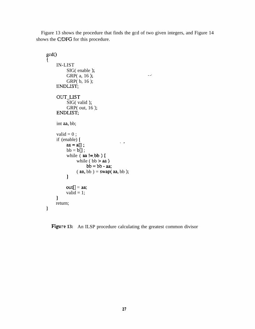
Figure 13 shows the procedure that finds the gcd of two given integers, and Figure 14shows the C/DFG for this procedure.
IN-LISTSIG( enable );GRP( a, 16 );GRP( b, 16 );
ENDLIST,
OUT-LISTSIG( valid );GRP( out, 16 );
ENDLIST;
int aa, bb;
valid = 0 ;if (enable) { . .
aa=aO;bb = b[] ;while ( aa !=.bb ) {
while ( bb > aa )bb=bb-aa;
( aa, bb ) = swap( aa, bb );1
out[] = aa;valid = 1;
1return;
1
Figr2 13: An ILSP procedure calculating the greatest common divisor
27

e
Tn”6)a
3.
fla se
Figure 14: Graph representation of the ILSP procedure in Figure 13
28

A. Graph Data StructuresThe Hermod program is implemented in C++, an objected oriented programming
language. The internal representations of the C/DFG are described in this section. TheC/DFG is implemented around three linked lists, node-list, edge-list, and sub-graph.
A.I. Node Data StructureThe struct node-fist holds the information of the nodes in the C/DFG. The following
data structure is used for the data and control nodes.
struct node-list (int type ;int attr ;struct caselabel * cl;struct symtable * ps ;struct edge-list * pe ;struct node-list * next ;int in ;int out ;vo id*pwl ;void * pw2 ;class NList * pN ;struct hardware * hw ;int num ;struct basicblock * bb ;int dfn ;int tclevel ;class HUnit * hu ;
1;
/* DATA, CONTROL, OP, CONST, or TMP *//* node attribute *//* pointer to case label table *//* pointer to the symbol table. *//* pointer to the edges connected to it *//* pointer to the next entry *//* in-degree *//* out-degree *//* work area 1 *//* work area 2 *//* pointer to the object for drawing *//* pointer to the hardware information *//* node number *//* basic block, for control node *//* data flow number, for operation node *//* timing-cut level *//* pointer to the associated hardware unit */
The meaning of each field in the struct node-list is briefly described.l int type - shows the node type, values.
l int attr - shows the attribute of the node. The attribute, for example, meanskind of operation for operation nodes, kind of control for control nodes, andconstant value for constant nodes.
l struct symtable *cl - is a pointer to the mapping table between portnumber and case label (case constant). This pointer is valid only for sforknode. This pointer is NULL for other types of nodes.
l struct symtable *ps - is a pointer to the entry in the symbol table. Thispointer is meaningful for data nodes, temporary nodes and the procedurecall nodes. This pointer is NULL for the other types of nodes.
l struct edge list *pe - is a pointer to the first entry of the edges connected
29

to this node.
l struct node list *next - is a pointer to the next entry of the node-list.
l int in - is a number of in-coming edges.
l int out - is a number of out-going edges.
l void *pwl, void *pw2 - are used as working storages.
l class NList *pN - is a pointer to the object for drawing. This pointer is setby the drawing procedure.
l struct hardware *hw - is a pointer to the hardware information assignedthe node.
l int num - is a node identification number. This number is zero or positiveinteger. See next section for detail.
l struct basicblock *bb, int dfn - are set by the data flow analysis programto indicate which basic block this node belongs to.
l int tclevel - represents the timing-cut level.
l class HUnit *hu - is a pointer to the associated hardware unit in the datapath built from this C/DFG.
Node Identification Number:
The node identification number is used not only for identifying each node but also fordrawing on the screen. The graph drawing routine draws and displays the graph basedon the node identification number. The following numbering rules are applied to drawgraphs.
The Node Numbering Rules:1. The start node should have the node identification number 0.
2. If node nl has an out-going edge to node n2, the node identificationnumber of nl should be greater than that of the node n2.Exception: This rule does not apply to the start node.
3. If node nl is in the subgraph corresponding to the then-part of an if-statement and node n2 is in the subgraph corresponding the else-part, thenthe node identification number of the node nl should be greater than thatofthenoden2.
4. If the node nl is in the subgraph corresponding to the n-th case statementof a switch statement and the node n2 is in the subgraph corresponding tothe m-th case statement where m > n or the default statement of the switchstatement, then the node identification number of the node nl should begreater than that of the node ~22.
30

Figure 15 shows the legal node numbering. Nodes are numbered sequentially from 0to the number of nodes according to the linking order in the node-fist maintained by thesynthesis system. Thus, the linking order of nodes in the node-list should follow theabove rules.
9
+.
6
Figure 15: Node numbering
A.2. Edge Data StructureThe struct edge-list holds the information for edges in the graph.
struct edge-list {int type ;int io ;int port1 ;struct node-list * pair ;int port2 ;struct edge-list * mirror ;struct edge-list * next ;class EList * pE ;edgetype et ;int tcount ;
/* edge type *‘//* in-coming or out-going *//* port of origin node *//* pointer to the pair node *//* port of the pair node *//* pointer to the mirror edge. *//* pointer to the next edge *//* pointer to the object for drawing *//* edge type *//* number of timing-cuts in the edge */
31
int tcwork ; /* work area for the timing-cut functions */class List * tcuts ; - /* timing-cuts to which this one belongs */int mark.; /* used in the automatic timing-cut function */int num ; /* edge number */
1;
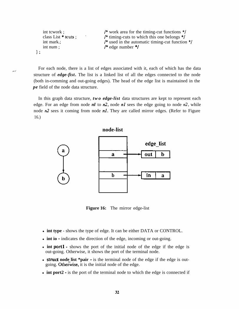
For each node, there is a list of edges associated with it, each of which has the datastructure of edge-fist. The list is a linked list of all the edges connected to the node(both in-comming and out-going edges). The head of the edge list is maintained in thepe field of the node data structure.
In this graph data structure, two edge-list data structures are kept to represent eachedge. For an edge from node nl to 12, node nl sees the edge going to node ~2, whilenode n2 sees it coming from node nl. They are called mirror edges. (Refer to Figure16.)
node-list
b -
Figure 16: The mirror edge-list
l int type - shows the type of edge. It can be either DATA or CONTROL.
l int io - indicates the direction of the edge, incoming or out-going.
l int port1 - shows the port of the initial node of the edge if the edge isout-going. Otherwise, it shows the port of the terminal node.
l struct node list *pair - is the terminal node of the edge if the edge is out-going. Other&e, it is the initial node of the edge.
l int port2 - is the port of the terminal node to which the edge is connected if
32

the edge is out-going. Otherwise, it is the port of the initial node.
l struct edge list *mirror - is a pointer to the mirror edge.
l struct edge list *next - is a pointer to the next entry of the edge-list.
l class EList *pE - is the pointer to the object for drawing.
l edgetype et - takes the integer value; NORMAL, BACK, TIMING-CUT, orB-AND-T. Each type is described in previous sections.
l int tcount - is the number of the timing-cuts on the edge.
l class List *tcuts - is the linked list of the time-cuts to which the edgebelongs.
l int num - is the unique id.
A.3. SubGraph Data StructureThe struct subJraph holds the head pointer to the start node of a data flow graph
which corresponds to a procedure in an ILSP program.
struct sub_graph {int num ;struct node-list * start ;struct sub_graph * next ;struct basicblock * bb ;struct dfntable * trtable ;
class List * timing-cuts ;class GraphData * gd ;class StatDgrm * sd ;class DataPath * dp ;
I;
/* sub_graph identification number *//* pointer to the start node *//* pointer to the next entry *//* the basic blocks for this graph *//* the data flow translation table,
associate data flow number to graph a node *//* linked list of the timing-cuts *//* pointer to the object for drawing *//* pointer to the state diagram *//* pointer to the data path graph */
l struct node list *start - is the pointer to the start node.
l struct sub-graph *next - is the pointer to the next subgraph.
l struct basicblock *bb, struct dfntable *trtable - are used in the data flowanalysis routine. The table (pointed to by trtable) maps a data flow numberto a graph node and a symbol table entry which contains information abouteach identifier.
l class List *timing cuts - is the list of timing-cuts imposed on this C/DFG.
l class GraphData *gd - is the pointer to the data structures for drawing theC/DFG on the screen.
l class StatDgrm *sd, class DataPath *dp - are the pointers to the data
33
structures that maintain the hardware assignment information.
A.4. Other Data Structures1) The data structure carelabel holds a mapping table entry between a port of the
sfork control node and a case constant. This is used only for the sfork nodes.
struct caselabel (int port ;int label ;struct caselabel * next ;
1;
/* port number *//* case constant *//* pointer to the next entry */
2) The data structure timing-cut holds the information on a timing-cut on an edge.Timing-cuts on an edge are kept in the field tcuts of the structure edge-fist, and all thetiming-cuts in the subgraph are kept at the timing-cuts field in the structure subJraph.
struct timing-cut (int id ;List * edges ;TimingNode * pN ;int level ;short drawn ;
1;
/* timing-cut identification number *//* edges belonging to this timing-cut *//* pointer to the object for drawing. *//* relative position of the timing-cut *//* flag for checking if already drawn */
3) The basicblock structures maintain the list of nodes belonging to a particular basicblock and the information on the usage of data nodes. They also contain state bindingand hardware representation information of the subgraph.
4) The class List is an implementation of the double-linked circular list. It can holdpointers to any data type. The classes NList, EList, GraphData are derived classes ofthe class List and used for drawing on the screen.
5) The classes StatDgrm and DataPath hold the information on the hardwaregenerated from the C/DFG by the synthesis tools. They are tightly coupled with theC/DFG data structure by pointers so that the original C/DFG information can beretrieved easily from these classes.
34
ReferencesHI R. Alverson, T. Blank, K. Choi, S.Y. Hwang, A. Salz, L. Soule, and T. Rokicki.
THOR User’s Manual: Tutorial and Commands.Technical Report CSL-TR-88-348, Stanford University, Stanford, CA, January,
1988.
PI R. Alverson, T. Blank, K. Choi, S.Y. Hwang, A. Salz, L. Soule, and T. Rokicki.THOR User’s Manual: Library Function.Technical Report CSL-TR-88-349, Stanford University, Stanford, CA, January,
1988.
131 A. Orailoglu and D.D. Gajski.Flow Graph Representation.In Proc. 23rd Design Automation Conf., pages 503-509. ACM/IEEE, June,
1986.
141 B.M. Pangrle and D.D. Gajski.Design Tools for Intelligent Silicon Compilation.IEEE Trans. Computer-Aided Design of Integrated Circuits and Syst.
CAD-6(6): 1098- 1112, November, 1987.
35