the impact of high frequency/low energy seismic waves on
TRANSCRIPT

The Impact of High Frequency/Low Energy Seismic
Waves on Unreinforced Masonryby
Patrik K. Meyer
Submitted to the Department of Civil and Environmental Engineeringin partial fulfillment of the requirements for the degree of
Master of Science
At the
MASSACHUSETTS INSTITUTE OF TECHNOLOGY
September 2006
@ 2006 Massachusetts Institute of Technology. All rights reserved.
7..,Author ........ . -.. .......... . ........ ........ .......................
Department of Civil and Environmental Engineering, - August 10, 2006
Certified by ........... .- . ............. e ... ............... ...................
John OchsendorfAssistant Professor of Building Technology
Thesis Co-Supervisor
C ertified by ...... ............... ......................................... . . ............
John T. GermainePrincipal Research Associate of4ran finviWnmental Engineering
Thesis Co-Supervisor
Accepted by ..... ......... ....................... : ........... •. ...................Andrew Whittle
Chairman, Department Committee on Graduate Students
ARCHIVES
OF TECHNOLOGY
DEC 0 5 2006
LIBRARIES
- -


The Impact of High Frequency/Low Energy Seismic
Waves on Unreinforced Masonryby
Patrik K. Meyer
Submitted to the Department of Civil and Environmental Engineeringon August 10, 2006, in partial fulfillment of the requirements for the degree of
Master of Science in Civil Engineering
Abstract
Traditionally, the high frequency components of earthquake loading are disregarded as a sourceof structural damage because of their small energy content and because their frequency is too high toresonate with the natural frequencies of structures. This thesis argues that higher frequency wavestravelling through stiff masonry structures can trigger two types of failure mechanisms that have not yetbeen taken into account. First, the high frequencies can cause small vertical inter-stone vibrations thatresult in irreversible relative displacements of the stones, which may ultimately lead to collapse. Theenergy needed to cause this deformation and failure comes largely from gravitational forces. The secondfailure mechanism is associated with the increase of the outward thrust that results from the partialfluidization and densification of the loose granular inner core of some unreinforced masonry walls.Preliminary results of a series of static and dynamic tests, as well as of numerical models, demonstrate thepotentially destructive effects of high frequency/low energy seismic waves on unreinforced masonrystructures.
Thesis Supervisor: John OchsendorfTitle: Assistant Professor of Building Technology
Thesis Reader: Eduardo KauselTitle: Professor of Civil and Environmental Engineering
Thesis Reader: John GermaineTitle: Principal Investigator of Civil and Environmental Engineering


Acknowledgments
I would first like to thank my advisors Assistant Professor John Ochsendorf, Dr. John Germaine,
and Professor Eduardo Kausel for their support and guidance. Then, I want to thank the Hugh
Hampton Young Memorial Fund Fellowship at MIT for its financial support. In addition, the
NSF funds facilitated by the MIT-India program made it possible to conduct research at the
Indian Institute of Technology, Bombay over the summer of 2005. I am especially thankful for
the support obtained from Mr. Nissar Khan and his helpful team during the testing period on the
shake table of the IITB's Laboratory of Heavy Structures. I also want to thank Tom Kachoris Jr.,
President of Spaulding Brick Co., Inc. and Howard Bourdelais from Modem Continental, for
generously donating the bricks and materials needed to construct the walls built in the MIT
laboratory. Finally, I thank Thanh-Hue Huynh, from the Technical University of Karlsruhe, for
helping with the construction and testing of a number of walls.

List of FiguresFIGURE 1-1. (A) DELAMINATED STONE WALL IN AL-HOCEIMA, MOROCCO; (B) CRUMBLED CORNER
OF A STONE DWELLING IN BAM, IRAN. ........................................................... 13FIGURE 1-2. GRAPHICAL DESCRIPTION OF THE FAILURE MECHANISM TRIGGERED BY HIGH
FREQUENCIES: (A) A TWO-WYTHE MASONRY WALL WITH A RUBBLE INFILL; (B) STONES AREDISPLACED DUE TO VIBRATIONS; (C) INTERNAL LATERAL PRESSURE DUE TO RUBBLE IS
INCREASED; AND (D) THE WALL COLLAPSES ........................................... ................. 14
FIGURE 1-3. A) SEISMIC HAZARD MAP OF INDIA; B) DEMOGRAPHIC MAP OF INDIA .................... 16FIGURE 1-4. (A) COLLAPSED ROUNDED STONE MASONRY HOUSE; (B) OUT-OF-PLANE FAILURE
(SOURCE: BBC) ....................................................................................... ................... 17FIGURE 1-5. WALL DELAMINATION IS A VERY COMMON FAILURE MECHANISM OF UNREINFORCED
STONE M ASONRY. ............................................................................ .................................. 19FIGURE 1-6. (A) STONE MASONRY WITH THICK JOINTS; (B) PARTIALLY DAMAGED DOME .............20FIGURE 1-7. (A) HEAVY ROOFS; (B) NO ROOF-WALL CONNECTIONS A COMMON PROBLEM ..........20FIGURE 1-8. (A) DAMAGE TO URM STRUCTURES; (B) BUNGA HOUSE; (C) DESTROYED VILLAGE
(PHOTOS: ERIC M ARTI)............................................. ........................................................ 22FIGURE 2-1. COMPARISON OF SPECTRAL CONTENTS OF POKHRAN AND CHANGHAI EXPLOSIONS AT
SIMILAR EPICENTRAL DISTANCES (GUPTA ET AL., 1998)......................................................... 25FIGURE 2-2. VERTICAL GROUND VIBRATION VELOCITY AT A DISTANCE OF 4 M FROM THE
COMPACTION PROBE DURING PROBE PENETRATION AND RESONANCE COMPACTION (SOURCE:
M ASSARSCH 2005). ......................................................... .................................................. 26FIGURE 2-3. PASSIVE AND ACTIVE EARTH PRESSURES; H IS THE WALL HEIGHT; Y IS THE WALL
DISPLACEMENT (US ARMY CORPS OF ENGINEERS 2005) ...................................... ... 28FIGURE 2-4. FREE BODY DIAGRAM OF THE FORCES ACTING ON A WALL WYTHE, INCLUDING THE
VERTICAL SHEAR (VS) AND NON-LINEAR LATERAL SOIL PRESSURE.........................................29
FIGURE 2-5. QUALITATIVE COURSES OF WALL NORMAL STRESSES, AND ASSUMED TRAJECTORIES OF
THE MAJOR PRINCIPAL STRESS (SOURCE: SCHULTZE 2005)................................. ..... 29FIGURE 2-6. AN EXAMPLE OF A DEM WHERE BOTH THE WALL UNITS AND THE INFILL ARE MODELED
W ITH DISCRETE ELEMENTS ............................................ .................................................... 32FIGURE 3-1. THE FOUR MAIN TYPES OF SEISMIC WAVES: (A) P-WAVE; (B) S-WAVE; (C) RAYLEIGH
WAVE; (D) LOVE WAVE (BRAILE) ............................................................... 38FIGURE 3-2. PARAMETERS DEFINING THE PROPERTIES OF A WAVE (BRAILE). .............................. 38
FIGURE 3-3. (A) COMPARATIVE DRAWINGS OF LOOSE AND COMPACTED SOILS; (B) REDUCTION OF
SHEAR MODULUS AND SHEAR WAVE VELOCITY AS A FUNCTION OF SHEAR STRAIN (RAINER
M A SSA RSCH ) .......................................................................................................................... 42FIGURE 3-4. GRAINS IN SILOS: NATURAL MASS FLOW AND ARCHING, (SCHULZE). ....................... 43FIGURE 4-1. HORIZONTAL PRESSURES EXPERIENCED BY A RETAINING WALL TAKING INTO ACCOUNT
THE ARCHING EFFECT (SOURCE: TAKE AND VALSANGKAR 2001) ...................................... 46FIGURE 4-2. A) WALL HEIGHT NEEDED FOR SLIDING FAILURE. B) WALL HEIGHT NEEDED FOR
OVERTURNING FAILURE, SHOWING THAT A MINIMUM WALL HEIGHT OF 60CM IS NEEDED TO
CAUSE OVERTURNING. .............................................. ......................................................... 47FIGURE 4-3. A) BRICK WALL WITH TRANSPARENT INFILL BOUNDARY; B) TYPICAL STONE WALL. ...51
FIGURE 4-4. GRAVEL MODELED WITH CIRCULAR CRACKS: (A) BEFORE CRUMBLING; (B) AFTER
CRUMBLING, SHOWING THE ANGLE OF REPOSE ..................................................................... 52
FIGURE 4-5. WALL DELAMINATION PROCESS ......................................................... 53

FIGURE 4-6.(A) STONE WALL MODEL; (B) MODEL WITH THROUGH-STONES............................54FIGURE 5-1. EFFECT OF FRICTION ANGLE ON FAILURE HEIGHT: INCREASING FRICTION ANGLE
RESULTS IN AN INCREASE OF THE WALL FAILURE HEIGHT. ..................................... ..... 56FIGURE 5-2. FRICTION ANGLE VERSUS STATIC AND DYNAMIC FAILURE HEIGHTS FOR BRICK WALLS:
INCREASING FRICTION ANGLE RESULTS IN AN INCREASE OF THE WALL FAILURE HEIGHT. ....... 58
FIGURE 5-3. FREQUENCIES AND ACCELERATIONS NEEDED TO INDUCE OVERTURNING FAILURE INBRICK W A LLS .............................................................................. ...................................... 58
FIGURE 5-4. A) FIRST STAGE: DENSIFICATION OF THE INFILL RESULTING IN A REDUCTION OF 10% OFINFILL HEIGHT; B) SECOND STAGE: WALL WYTHES ARE PUSHED APART DUE TO INCREASEDINTERNAL PRESSURE FROM SHEAR FLUIDIZATION OF THE INFILL; C) THIRD STAGE: WALLSEITHER WHOLLY DEFORMED OR COLLAPSED ..................................................... 60
FIGURE 5-5. FREQUENCIES AND ACCELERATIONS NEEDED TO CAUSE FULL FAILURE OF THE BRICKW A LL S. ................................................................................................................................... 6 1
FIGURE 5-6. FAILURE FREQUENCIES AND ACCELERATIONS FOR STONE WALLS. ........................... 62
FIGURE 5-7. THE UDEC STATIC MODEL WITH COARSE GRAVEL-SIZED INFILL MATERIAL. A) INITIAL
STATE OF THE MODEL JUST AFTER APPLYING THE GRAVITATIONAL FORCE TO THE MODEL; B)FAILURE ONSET AFTER TWO SECONDS; C) FAILED STATE AFTER FOUR SECONDS...................63
FIGURE 5-8. A) PLOT OF THE IMPENDING FAILURE HEIGHT OF THE MODEL GIVEN DIFFERENT
FRICTION ANGLES OF THE INFILL MATERIAL; B) ANALYTICAL MODEL USED WITH CIRCULARINFILL. .................................................... 64
FIGURE 5-9. PLOT OF THE INFILL MATERIAL'S FRICTION ANGLE NEEDED TO ALLOW FOR A GIVENINFILL WIDTH TO BE STABLE. A 90CM HIGH MODEL WAS USED IN ALL ANALYSES ................ 65
FIGURE 5-10. MODELS WITH CONSTANT HEIGHT AND VARYING INFILL WIDTH. ........................... 65
FIGURE 5-11. FAILURE MODES FOR MODELS OF SAME HEIGHT AND DIFFERENT WIDTH. ...............66FIGURE 5-12. HORIZONTAL ACCELERATION NEEDED TO CAUSE THE FAILURE WITH DECREASING
M ODEL HEIGHTS ............................................................................ .................................... 67FIGURE 5-13. VERTICAL ACCELERATION NEEDED TO CAUSE THE FAILURE WITH DECREASING MODEL
H EIG H TS ................................................................................. ........................................... 68FIGURE 5-14. PLOT SHOWING THE MAXIMUM ACCELERATION NEEDED TO CAUSE FAILURE OF A
SPECIMEN OF A GIVEN HEIGHT.......................................................................................... .... 69FIGURE 5-15. A) MODEL FAILING THROUGH SLIDING OF THE BRICKS; B) MODEL AFTER INITIAL
ROTATION OF THE WYTHES. ..................................................................... 69FIGURE 5-16. (A) MODEL OF TWO-WYTHE STONE WALLS WITHOUT THROUGH-STONES; (B) MODEL
WITH TWO THROUGH-STONES; (C) MODEL WITH FOUR THROUGH-STONES. .......................... 70FIGURE 5-17. (A) FAILURE AT 0.19G; (B) FAILURE AT 0.32G; (C) FAILURE AT 0.45G ................... 70FIGURE 5-18. PLOT OF THE ACCELERATION NEEDED TO CAUSE THE FAILURE OF THE MODELS WITH
DIFFERENT NUMBERS OF THROUGH-STONES ...................................................... 71FIGURE 6-1. (A) DELAMINATION OF A DRY STONE WALL WITH NO THROUGH-STONES; (B) THROUGH-
STONE SOLUTION . ............................................................................ .................................. 74FIGURE 6-2. (A) WALL CORNER WITH THROUGH-STONES AND BIG, UNIFORM CORNER STONES; (B)
THROUGH STONE MADE WITH FOUR UNITS OF SMALLER STONES. ............................................ 74FIGURE 6-3. RECOMMENDED OPENING PROPORTIONS FOR A ONE-STORY, UNREINFORCED STONE
HOUSE (SOURCE: ARYA 2005). .......................................................................................... 75FIGURE 6-4. "TEMPLES IN KYOTO WITH HANCHIKU SEISMIC ISOLATION. THE INLETS SHOW
CONFINING SEAL OF CHALKY CLAY AND BASE ROCKS TO KEEP SETTLEMENTS AT ACCEPTABLELIMITS." (SOURCE: GUDEHUS 2004) ..................................................... ......... .......... 76

FIGURE 6-5. (A) STONE LAID IN THICK MUD MORTAR; (B) DRY MUD MORTAR FALLING OUT OF THE
JOINTS LEAVING VOIDS AROUND THE STONE UNITS. ..................................... ........... 78FIGURE 6-6. OUT-OF-PLANE FAILURE OF A LONG, CONTINUOUS WALL. ..................................... 79FIGURE 6-7. INTRODUCTION OF CROSS-WALL TO IMPROVE THE OUT-OF-PLANE BEHAVIOR ...........79
FIGURE 6-8. ROOF-WALL CONNECTION SYSTEM USING DOWELS AND WIRES (DRAWINGS BY: YANNIL O U K ISSA S) ............................................................................................................................ 80
FIGURE 6-9. ROOF-WALL CONNECTION SYSTEM USING TIMBER MEMBERS (DRAWINGS BY: YANNIL O U K ISSA S) ............................................................................................................................ 8 1
Note: all photos by author unless indicated.

ContentsABSTRACT 3
ACKNOWLEDGMENTS 5
LIST OF FIGURES 6
CONTENTS 9
CHAPTER 1 12
1. INTRODUCTION 12
1.1 Background 12
1.2 Problem Statement 12
1.3 Motivation 151.3.1 Global Risk Assessment 15
1.4 Masonry Behavior in Recent Earthquakes 161.4.1 Kashmir - Pakistan 171.4.2 Bam - Iran 191.4.3 Bhuj - India 21
1.5 Discussion 22
1.6 Thesis Outline 23
CHAPTER 2 24
2. LITERATURE REVIEW 24
2.1 High Frequency Seismic Vibrations and Masonry Structures 24
2.2 Shear Fluidization of Granular Soils 26
2.3 Granular Soil-Structure Interaction 272.3.1 Retaining Walls 272.3.2 Silos 29
2.4 Conventional Methods to Analyze URM 302.4.1 Finite Elements Method: FEM 302.4.2 Discrete Elements Method: DEM 312.4.3 Distinct Panels 322.4.4 Probabilistic Risk Assessment 33

2.5 Discussion 34
CHAPTER 3 35
3. BACKGROUND INFORMATION AND THEORY 35
3.1 Unreinforced Stone Masonry (URSM): Advantages and Disadvantages 353.1.1 Advantages 353.1.2 Disadvantages 36
3.2 Unreinforced Brick Masonry (URBM): Advantages and Disadvantages 363.2.1 Advantages 363.2.2 Disadvantages 37
3.3 Seismic Waves 37
3.4 Frequencies 39
3.5 Shear Fluidization and Ratcheting 40
3.6 Compaction of Dry Granular Soils 41
3.7 Arching Phenomenon 42
3.8 Discussion 43
CHAPTER 4 45
4. METHODOLOGY 45
4.1 Preliminary Evaluation 45
4.2 Static Tests: Brick Walls 48
4.3 Dynamic Test: Brick and Stone Walls 494.3.1 Vertical Vibrations 494.3.2 Horizontal Vibrations 50
4.4 Analytical Models: Brick Walls 51
4.5 Analytical Models: Stone Wall Delamination 52
4.6 Discussion 54
CHAPTER 5 56
5. RESULTS 56
5.1 Static Tests: Brick Walls 56

5.1.1 Influence of Granular Infill Friction Angle
5.2 Dynamic Tests 575.2.1 Vertical Vibrations: Brick Walls 575.2.2 Horizontal Vibrations: Brick Walls 595.2.3 Horizontal Vibrations: Stone Walls 61
5.3 Analytical Model 625.3.1 Static Conditions 625.3.2 Dynamic Conditions 66
5.4 Discussion 71
CHAPTER 6 73
6. LOW-COST REMEDIAL ACTIONS 73
6.1 New Construction 736.1.1 Through-Stones and Stone Shape 736.1.2 Distribution and Proportions of Openings 756.1.3 "Hanchiku" Seismic Base Isolation 75
6.2 Retrofit 776.2.1 Through-Stones and Cementicious Mortar 776.2.2 Room Partitions 786.2.3 Roof-Wall Connection I 796.2.4 Roof-Wall Connection II 80
6.3 Discussion 81
CHAPTER 7 83
7. CONCLUSIONS AND FUTURE WORK 83
BIBLIOGRAPHY 85
APPENDIX 1: UDEC SCRIPTS 88
APPENDIX 2: PAMPHLET DISTRIBUTED IN KASHMIR 06 90

Chapter 1
1. Introduction1.1 Background
In developing countries, more unreinforced masonry structures exist than any other type of
structure (UN-Habitat 2005), and such structures are the least seismically safe (Government
Code 2004). Recent earthquakes, such as those in Pakistan (2005), Bam (2003) and Gujarat
(2002), have raised awareness of the need for scientific methods to assess the structural integrity
of unreinforced construction under seismic loading, and of methods to increase their
performance. Years of earthquake research and laboratory testing have demonstrated that houses
and buildings built with brittle materials are intrinsically unsafe under seismic loading and
require remedial reinforcement to guarantee an acceptable degree of ductility. Despite this
research, however, the actual failure mechanisms of brittle masonry construction remain obscure
and poorly understood. The methods used in developing countries for low cost construction are
highly variable and based on empirical rules rather than on an understanding of structural
behavior and performance. Because of the inherent complexity and variability in masonry
materials and construction methods, such structures are difficult to model effectively with
numerical methods. Current analytical methods are based on a number of major simplifications,
such as the pure brittle behavior and isotropy of masonry. These simplifications lead to models
that often are not representative of the actual structures, and it is difficult, if not impossible, to
determine the many structural and constitutive parameters needed for such numerical models.
This is especially true in seismic situations, which involve loading and unloading, fracture
propagation, contact and slip, and other considerations.
1.2 Problem Statement
From our observations in the field, we have learned that the failure mechanisms often involve the
aggregation of irreversible "stick-and-slip" processes between bricks or stones (Kolb et al. 1999).
The stick-and-slip process results in a gradual release of gravitational energy and dislocation of
structural elements from their stable positions in walls (Figure 1-1). Frequencies higher than 10

Hz could be the source of these processes and may cause two failure mechanisms that have not
yet been accounted for.
(a) (b)
Figure 1-1. (a) Delaminated stone wall in Al-Hoceima, Morocco;in Bam, Iran.
(b) Crumbled comer of a stone dwelling
The first failure mechanism affects stone masonry structures and is triggered by high
frequency vibrations that excite inter-stone vibrations. Relative displacement of the stones may
accumulate from repeated stick-slip processes elicited by these vibrations, inasmuch as the
stones are frequently oblong or pyramidal, with their bases oriented toward the exposed part of
the wall (Fig. 2a). Their irregular shape facilitates the irreversible downward sliding of the
stones, leading to a relative displacement of the masonry units (Figure 1-2b-c). As a consequence
of this relative movement of the stones, the wall becomes deformed and unstable, leading to
catastrophic collapse under its own weight.
The energy needed to cause this deformation and failure mechanism does not come
predominantly from the earthquake waves, as is commonly assumed, but from the release of the
potential energy stored in the structure. That is, the energy needed to cause the collapse of the
structure comes from the structure itself. Hence, small energy, high frequency seismic waves can
trigger the collapse mechanism of poorly built walls. Furthermore, the damaging effects of
higher frequencies are amplified by the fact that for frequencies higher than 10Hz, the vertical

accelerations are larger than the horizontal ones (Singh 2005), a situation that further reduces the
inherent cohesion of the masonry.
A second unaccounted for failure mechanism is associated with the increase in outward
thrust from the densification and fluidization-loss of shear strength due to particle vibrations-
of the wall's inner core granular material. In masonry walls, the inner core is often made up of
loose sand and gravel that tend to densify and fluidify when experiencing high-frequency
vibrations (Svinkin 2005), resulting in a significant increase of the lateral thrust. This additional
thrust will push the unstable masonry units outward causing the deformation and possible
collapse of the masonry skins. This failure mechanism will compound the effect of the
previously described inter-stone displacement elicited by the high frequency motion components,
as depicted in Figure 1-2.
rLL,Lr
==
(a) (b) (c) (d)
Figure 1-2. Graphical description of the failure mechanism triggered by high frequencies: (a) A two-wythe masonry wall with a rubble infill; (b) stones are displaced due to vibrations; (c) internal lateralpressure due to rubble is increased; and (d) the wall collapses.
To study the failure mechanisms described above, a series of laboratory scale brick walls
were built and tested to identify the heights at which the walls were statically stable with
different sized infill. Then, a second series of similar brick walls, as well as a number of stone
walls were tested to observe their dynamic behavior. Finally, UDEC, a discrete element
modeling software, was used to analyze the brick walls and compare the results with those
obtained experimentally. The results obtained from this research validate the significance of the
damaging effects of higher frequencies on the overall structural stability of unreinforced
masonry.

1.3 Motivation
1.3.1 Global Risk Assessment
With over 2.8 billion people living on less than $2 a day and almost half of them on less than $1
a day, there is a dire need in developing countries for no-cost housing. It is estimated that "1.1
billion people are living in inadequate housing conditions in urban areas alone." (UNCHS 1999)
In addition, some 35 million housing units each year would be needed to fill the current housing
deficit and meet the growth of households in developing countries. Buying expensive
construction materials is not an option for the majority of the people living on and under the
poverty line. Therefore, they have to make recourse of their ingenuity and the materials they can
gather in their environment. Two construction materials that are readily available to them are
soil and stones. These materials can be safely used as construction materials if employed
appropriately in non-seismic regions. However, in seismic-prone regions, the performance of
unreinforced dry stone masonry and brick masonry is poor. Hence, it is imperative to follow
much stricter construction rules than in non-seismic regions to build safe structures.
To illustrate the magnitude and urgency of this situation, the case of the Indian housing
condition will be analyzed next in more details. The Indian Subcontinent with a population of
over 1.1 billion is one of the most disaster-prone regions in the world (BMTPC 2000):
* 54% of land is vulnerable to earthquakes
* 8% of the land is vulnerable to cyclones
* 5% of the land is vulnerable to floods
These hazards cause the damage or destruction of over one million houses per year, with
consequent human, social, and economic impact. Figure 1-3a) shows the seismic hazard map for
India and Figure 1-3b) shows the population map of India. From these two maps it can be
observed that over 30% of the country's population (330 million) lives in seismically active
regions. 85% of India's building stock -165 million housing units- is composed of earthen,
brick, and stone buildings (Arya 2005). Taking into account that more than 80% of the Indian
building stock is not seismically safe, over 280 million people are living in 50 million homes that
are at risk of being severely damaged or destroyed during a moderate to strong earthquake. These
50 million homes are either unreinforced brick or stone masonry. In the cases where

reinforcement is part of the structure, which is often poorly designed and insufficient to carry
dynamic loads, masonry is still used as infill material within the reinforced frame.
1.
12
PAKISTA
Legend
0 MAN .
DADAR & NA 'AHAVEL
ARABIAN SEA P
24'
1"1.
(a) (b)
Figure 1-3. a) Seismic Hazard Map of India; b) Demographic Map of India
Many of the developing countries in Central-Asia, China, and Central and South-America are
in a similar hazardous situation as India, resulting globally in more than one billion people living
in mostly unreinforced or poorly reinforced masonry houses in seismic regions. An improved
understanding of unreinforced masonry (URM) structures under seismic loads is crucial to be
able to build safer house and design effective retrofit schemes.
1.4 Masonry Behavior in Recent Earthquakes
In this section the performance of URM in three recent earthquakes is assessed. These three
earthquakes occurred within a time frame of six years in different parts of the world and caused
between 35000 and 90000 deaths each. The number of casualties would climb at least an order of
magnitude if a strong earthquake were to hit a large metropolis like Teheran, Istanbul, or New
Delhi.
!P-Mb-16ý ý AMIL4U ALIMN % IOGOGAiIR SZANDS~
IWO~.l c)Ci·~l Illi~a PAl Lid 2001 02

1.4.1 Kashmir - Pakistan
The most recent major earthquake occurred in the region of Kashmir in Pakistan on October 8 th
2005. This magnitude 7.6 earthquake killed over 80,000 people, injured 200,000, and left over
four million homeless. A large share of the casualties and injuries in this rural region of Northern
Pakistan were the result of the collapse of unreinforced single-storey stone and brick masonry
buildings. Stone masonry houses are widespread in villages in the mountainous region of
Kashmir where stone is readily available. Stone masonry walls were poorly built with undressed
stones placed irregularly. In addition, the stones were often rounded (Figure 1-4a), further
weakening the overall stability of the house. The stones were often set in plain mud or at best in
1:10 sand/cement weak mortars (EERI 12/2005). This weak mortar was crushed during the
seismic loading, leaving gaps between the stones that accelerated the collapse of the houses. Out-
of-plane failure was another common failure mechanism observed during this earthquake (Figure
1-4b).
(a) (b)
Figure 1-4. (a) Collapsed rounded stone masonry house; (b) out-of-plane failure (Source: BBC)
As in most earthquakes, stone masonry structures performed very poorly during the Kashmir
earthquake. Three main structural reasons are the source of this poor performance. First, stone
walls are often built using two individual wythes that are not interconnected (Figure 6-1) which
allows them to act as two independent units, resulting in the delamination of the wall and its
crumbling. A second problem is that the area of the openings (windows and doors) is too large,
inadequately spaced, and unevenly distributed around the structure. This facilitates the initiation
and propagation of cracks, as well as the induction of torsional forces into the structure due to
stiffness eccentricities. The third major problem of this type of structure is that the individual
walls of the houses act independently of each other because there are no structural bands to tie
them together. This weakens the overall structure and results in the out-of-plane partial or total
collapse of the walls. Properly tying down the rigid roof to the walls would effectively bond
together the exterior walls, resulting in a box action of the overall structure and therefore
reducing the risk of out-of-plane failure of the individual walls (CUL 2005).
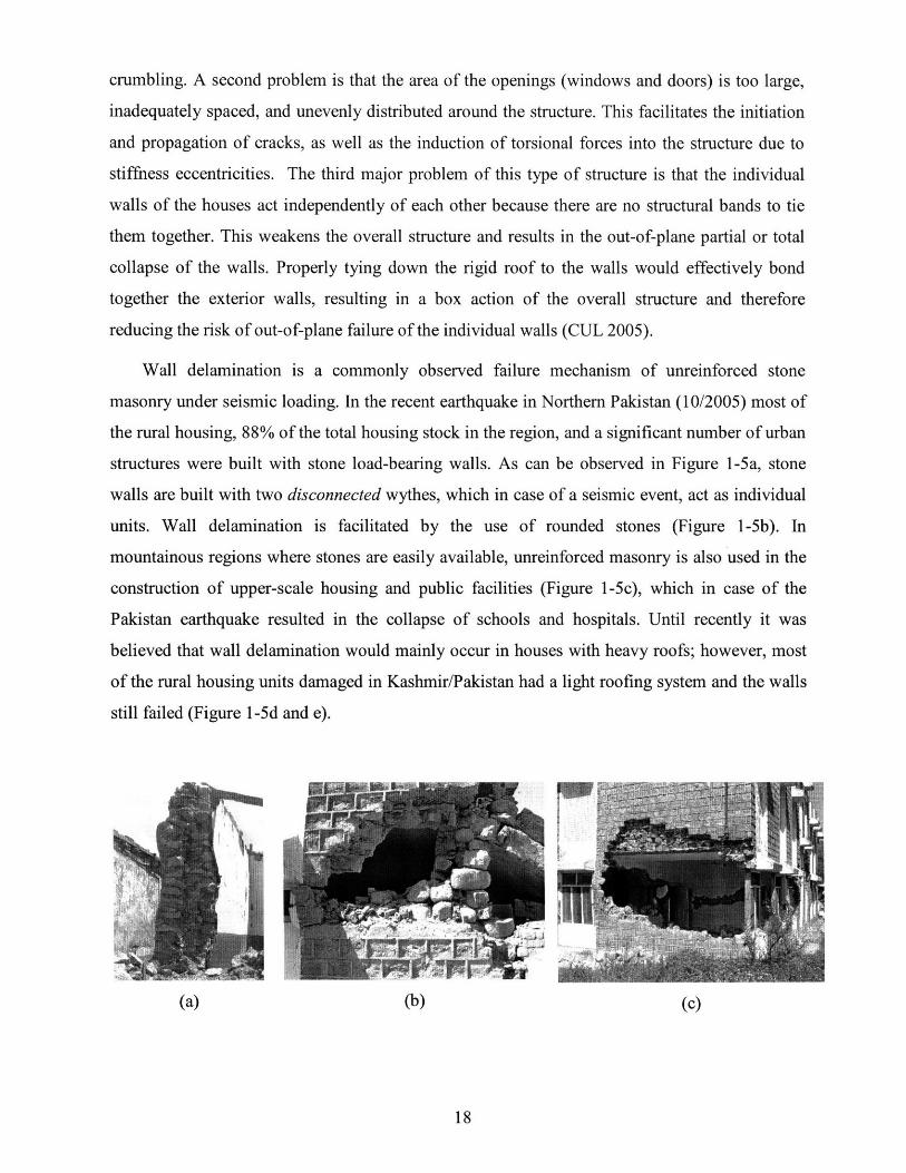
Wall delamination is a commonly observed failure mechanism of unreinforced stone
masonry under seismic loading. In the recent earthquake in Northern Pakistan (10/2005) most of
the rural housing, 88% of the total housing stock in the region, and a significant number of urban
structures were built with stone load-bearing walls. As can be observed in Figure 1-5a, stone
walls are built with two disconnected wythes, which in case of a seismic event, act as individual
units. Wall delamination is facilitated by the use of rounded stones (Figure 1-5b). In
mountainous regions where stones are easily available, unreinforced masonry is also used in the
construction of upper-scale housing and public facilities (Figure 1-5c), which in case of the
Pakistan earthquake resulted in the collapse of schools and hospitals. Until recently it was
believed that wall delamination would mainly occur in houses with heavy roofs; however, most
of the rural housing units damaged in Kashmir/Pakistan had a light roofing system and the walls
still failed (Figure 1-5d and e).
(a) (b)

(e)
Figure 1-5. Wall delamination is a very common failure mechanism of unreinforced stone masonry.
1.4.2 Bam - Iran
The December 2003 Bam 6.6 (Ms) earthquake was particularly fatal. Approximately 30% of the
90,000 strong population of Bam was killed and almost the totality was rendered homeless.
Before the earthquake, Bam was a prosperous small city. Yet, it took the earthquake less than
one minute to convert this wealthy and beautiful oasis into a pile of rubble. Over 45,000 people
were killed and 50,000 mostly unreinforced dwellings were destroyed in the region of Bam. The
most common construction materials used is adobe and solid earthen-fired bricks. The dwellings
built with these materials consisted of massive adobe bearing walls with vaulted or domed roofs
(Figure 1-6b). In the cases where stones were used, they were laid on thick mud-mortar joints,
making the structure very vulnerable to crumbling (Figure 1-6b) The most common failure
mechanisms were the out-of-plane failure and crumbling of the walls, followed by the collapse
of the heavy roofs (Figure 1-7a). It is interesting to note that many roofs were built using steel
beams. Unfortunately the beams were simply put on top of the walls with no further connection
between them (Figure 1-7b). This allowed the out-of-plane failure of the walls followed by the
collapse of the roof.
The Bam earthquake not only destroyed the city of Bam but also the 2000-year-old
citadel, Arg-e-Bam. Both the city and its citadel are sitting on top of the Bam thrust fault. It is
believed that many ancient and newer URM structures were destroyed due to the horizontal
accelerations combined with the vertical ones, which in this case peaked at around 1g. This high

vertical acceleration component resulted in the structures experiencing internal vertical absolute
forces that oscillated from none to twice their self-weight. The frictional forces between the brick
or stones were reduced to a minimum at the times when the structures were experiencing
minimal internal forces, allowing for the horizontal forces to cause relative horizontal
displacements between the different masonry units.
The vertical acceleration components of earthquakes are often ignored or disregarded in
current research and design of URM. As it will be shown later, vertical accelerations, especially
in the higher frequency range and near the faults, can be larger than the horizontal accelerations.
Therefore, the effect of the combination of both the horizontal and the vertical accelerations
should be taken into account in URM studies.
(a) (b)
Figure 1-6. (a) Stone masonry with thick joints; (b) partially damaged dome
(b)
Figure 1-7. (a) Heavy roofs; (b) no roof-wall connections a common problem

1.4.3 Bhuj - India
The Bhuj earthquake occurred on January 26, 2001 and had a maximum intensity of Mw7.6.
Over 350000 houses were fully destroyed and nearly one million damaged. About 50% of the
population of 40 million in the Indian state of Gujarat was directly or indirectly affected by this
disaster, which caused an excess of $5 billion in damages (CIRES 2001).
The large majority of the damaged structures were either stone or brick masonry (Figure
1-8a) with deficient or no reinforcement. In some villages, up to 95% of the houses collapsed or
were severely damaged as can be seen in Figure 1-8c. As was the case with Bam, Gujarat is a
wealthy state with enough resources to build earthquake-proof housing. In spite of being
wealthy, both reinforced and unreinforced structures were either poorly designed or built,
resulting in their deficient seismic performance. It is worthwhile to note that the traditional
locally built "Bungas" (Figure 1-8b), which are inhabited by the lower castes and poor,
performed quite well. This good seismic performance was the result of their circular shape,
which did not induce stress concentrations (Figure 1-8c).

(a)
(c)(b)
Figure 1-8. (a) Damage to URM structures; (b) Bunga house; (c) Destroyed village (Photos: Eric Marti).
1.5 Discussion
An excess of one billion people live in over one hundred million houses that are not seismically
safe in earthquake prone regions of the world (CHRR). Most of these houses are built with
masonry units and have no or deficient reinforcement. The dynamic behavior of URM still
remains to be accurately understood. The number of deficient, low-cost housing units is not
about to decrease: "The overwhelming shelter problem in the developing countries is the
shortage of affordable housing for the low-income majority of households in urban areas. This
has resulted in the proliferation of slums and squatter settlements"(UN-Habitat 1999). The
purpose of this research is to contribute to the better understanding of URM conducive to
improved construction practices and retrofit schemes.

1.6 Thesis Outline
This thesis first describes why the enormous global need for improved URM construction and
retrofit practices is the primary motivation for this research. Then, a literature review of the
topics of particular interest for this research is conducted. To ensure that the reader will fully
understand the issues discussed, background knowledge of the main concepts involved in the
experiments and results is provided and the pros and cons of stone and brick masonry are
presented. This is then followed by a detailed description of the experimental methodology used
during this research. Next, the behavior and failure mechanisms observed during the static and
dynamic experimental tests and the numerical models is analyzed and quantified, and a number
of significant detrimental effects of the seismic high frequencies on unreinforced masonry are
identified. Subsequently, a series of low-cost construction improvements and retrofit schemes are
proposed and described based on the observations made during the experiments and recent
earthquakes. Finally, the major conclusions are presented and the necessary future investigations
to further describe and quantify the effect of high frequency / low-energy seismic waves are
suggested.
Chapter 2
2. Literature ReviewThe first part of this chapter focuses on three major concepts that are at the core of a better
understanding of this research, namely the effect of high frequencies on structures, the shear
fluidization of granular soils and the soil-structure interaction in the case of retaining walls
and silos. Then, a brief overview of the strengths and shortcomings of conventional methods
for analyzing URM will be presented.
2.1 High Frequency Seismic Vibrations and Masonry Structures
The author has not been able to locate any scientific literature or research project directly
studying the impact of high frequency seismic vibrations on URM structures. The absence of
research in this field strongly suggests that high frequencies are not considered a threat to
structures, due mainly to two arguments. First, frequencies beyond 15Hz do not resonate with
the commonly built housing structures because they are higher than the structures' first
natural frequencies. As a rule of thumb, the natural frequency of a building in Hz is equal to
ten divided by the number of stories. This means that a ten-story building has a natural
frequency of 1Hz and a one-story building 10Hz. Second, the energy content (which is
proportional to the magnitude of the wave, Plate Techtonic 2005) of high frequency seismic
vibrations is very low, resulting in their being disregarded as a potential source of structural
damage.
Typical earthquakes show their highest energy contents at frequencies below 2-3Hz; the
1999 Bhuj earthquake had peak energy contents at frequencies around 2Hz, as can be seen in
Figure 2-1 (dotted line), where the energy content at different vibration frequencies of the
ground for two nuclear explosions can also be seen as a continuous line (Gupta et al., 1998). It
is interesting to note that the ground vibration frequencies at which the energy content is
highest in nuclear explosions occur between 4 - 6Hz. The total seismic energy released in an
earthquake (which is not the total energy released) is the sum of the energy content of the two
most significant seismic waves: P-waves and S-waves (which will be discussed later),
containing approximately 5% and 95% of the total radiated energy, respectively (Xyoli 2002).

3 * I
U1.2%
z
Figure 2-1. Comparison of spectral contents of Pokhran and Changhai explosions at similar epicentraldistances (Gupta et al., 1998).
Existing literature concurs that the energy content of seismic waves with frequencies
higher than 15Hz is much lower than at frequencies below 4Hz. However, the literature has
only recently started to address the significance of the frequencies of the seismic waves'
vertical component and how they could have a detrimental effect on structures.
"The vertical component of earthquake ground motion has generally been ignored in theseismic design of structures. However, this is gradually changing due to the increase innear-field records obtained especially in the last decade, and the field observations showingthe possible damaging effect of strong vertical motions." (Kambod et al. 2004)
During the 2003 earthquake in Bam the strong motion records showed that the maximum
horizontal accelerations were between 0.7 and 0.8g, whereas the maximum vertical
acceleration was about ig (Kambod et al. 2004).
The evident effect of the vertical accelerations resulting from the vertical vibration
component of seismic waves is that the structures' "self-weight" does not remain constant, but
rather oscillates over time. This will result in increasing and decreasing internal stresses that,
especially in the case of URM, affect the friction resistance between the different masonry
units (stone or brick), which in turn will influence the overall stability of the structure. This is
especially true in the case of dry stone masonry. Here the stability of the wall relies entirely
on the frictional resistance holding the stones together, which could be dramatically reduced
by vertical vibrations.
z

A more subtle effect of the vertical frequencies can be found on how these could affect
the core granular material of a two-wythe wall. This phenomenon has not been directly
studied in the URM context; however, studies have been conducted related to the resonance
frequencies of vibrated granular soils with the intention of achieving a better compaction. As
can be seen in Figure 2-2, dry granular soils show a resonance region between 12Hz and
20Hz, which will vary depending on the material properties and the overburden (Massarsch
2005). It is in the resonance domain that the shear fluidization of granular material will be
most significant.
iG
E14U
12.
109
a
U
n
5 10 15 20 26 3] 36FREEQUENC Y. Hz
Figure 2-2. Vertical ground vibration velocity at a distance of 4 m from the compaction probe duringprobe penetration and resonance compaction (Source: Massarsch 2005).
2.2 Shear Fluidization of Granular Soils
The study of shear fluidification in geotechnical engineering has become broader in recent
years, especially for earth-retaining structures. The U.S. Occupational Safety and Health
Administration OSHA warns that "granular soils are susceptible to shock and/or vibration
failure (OSHA 2004)." Richards et al. conducted extensive research on shear fluidization of
soils, and found that when the fluidization occurs, "material behaves as a fictional fluid rather
than yielding as a solid; it is as though the material had melted under stress" (Richards et al.
1990). Fluidization is used to describe the shear flow of material, which will increase as
acceleration increases, and should not be confused with the fundamentally different
liquefaction phenomenon. Moreover, fluidization can occur in granular soils with no pore
I

water, which is the case of interest for this research. In case of saturated loose soils, initial
fluidization will most probably cause liquefaction of the soil (Kumar 2001).
The investigation of the exact mathematical formulation of the shear fluidization is
beyond the scope of this paper; however, there are two important facts that are relevant to this
research. First, it is the horizontal, rather than the vertical, component of the acceleration that
will cause shear in the material and its fluidization. The vertical component can speed up the
fluidization process by reducing the net inter-particle frictional forces. Second, the horizontal
acceleration needed to initiate fluidification depends mainly on the type of soil and, to a lesser
degree, on its density. Sandy, dense soils will start fluidizing at horizontal accelerations of
0.295g, whereas loose sand start fluidizing at 0.28g. The relevance of soil fluidization in this
research is that it will result in an increase of outwards internal pressure on the wall wythes
coming from granular infill materials. This phenomenon has not yet been investigated in the
context of two-wythe unreinforced structures with granular infill, but has been extensively
addressed in the context of retaining walls. Therefore, for the purpose of better understanding
this phenomenon, the relevant literature on soil-structure interaction in retaining walls and
silos will be briefly reviewed.
2.3 Granular Soil-Structure Interaction
2.3.1 Retaining Walls
The design and behavior of retaining walls has been studied extensively. This review will
focus on the issue that is common to retaining walls and the wall specimens tested for this
research: lateral pressure on the wall wythes resulting from granular infill. There are two limit
states in lateral earth pressure acting on retaining wall, active and passive. At rest earth
pressure occurs when the wall is restrained and cannot move laterally. Passive earth pressure
develops when the pressures on the wall cause it to move into the soil. Finally, active earth
pressure develops when the wall moves outward (Figure 2-3). It is the active earth pressure on
a vertical cantilever retaining wall, which would be the non-arched, minimum tangential
stress that is analogous to the two-wythe brick wall with granular infill.

h
PASSIVE CASE ACTIVE CASE
Figure 2-3. Passive and active earth pressures; h is the wall height; y is the wall displacement (USArmy Corps of Engineers 2005).
The ratio of the horizontal and vertical stresses in homogeneous soils is given by the
coefficient of earth pressure at rest, K0:
Ko = oh/'v' and also Ko = 1 - sin 4',
for consolidated clays and granular soils, where 0' is the friction angle of the material. From
these two equations, given a vertical stress-h * (soil density)/area-and the friction angle of
the material, the limit lateral stress can be found. The effective lateral stress will be smaller
depending on the soil conditions. In the case of the masonry walls, the granular material is
restrained by two wythes standing close together, which results in some of the weight of the
infill material going into the wythes in the form of vertical shear forces, Vs, as seen in Figure
2-4. This transfer results in a non-linear increase of the lateral soil pressure q. This force
setup will be used in the calculations of lateral infill pressures.
\I
r"i7A
IMAaQ

h: wall height
w: wall width
P: vertical overburden
Ff: horizontal friction force
Fs: resultant of horizontal forces
q: lateral soil pressure. . . .. "11
- wI--
Figure 2-4. Free body diagram of theand non-linear lateral soil pressure.
forces acting on a wall wythe, including the vertical shear (Vs)
2.3.2 Silos
From the outside, a silo may look very different from a masonry wall. However, the stresses
generated by the stored granular material on the container walls show resemblance to those
occurring in a retaining wall or a two-wythe brick masonry wall. In Figure 2-5 four cross-
sectional cuts of a silo show the wall's normal stress, (ow, and the different assumptions of
what the trajectories of the principal stress could be (Schultze 2005). From these cross-
sections it can be seen that the stress distribution in the vertical section of a silo is similar to
the stresses in an infilled masonry wall. The research done on silos that is relevant to this
study is the one concerned with the change in internal pressures caused by the vibration of the
granular material.
Figure 2-5. Qualitative courses of wall normal stresses, and assumed trajectories of the major principalstress (Source: Schultze 2005).
tI

In the static case, the wall stresses in a brick wall with granular infill will be similar to
those found in silos: simple non-linear increase with depth. The main difference is that the
shape of the silo is pointed and the transition from the vertical wall to the slanted base can
cause stress concentrations. No such stress concentrations caused by wall slanting will occur
in a URM wall. In the dynamic case, the behavior of the granular infill, both in silos and
URM walls, will be similar; however, the failure mechanisms will be significantly different,
mainly due to the distinctive flow of material and stress concentrations in silos.
A number of catastrophic silo failures have been caused by flow-related dynamic load
conditions that had not been taken into account during the design process (Carson 2005).
Most of the failures are due to construction and design errors, and in a few cases due to silo
usage and maintenance. In a number of cases it has been observed that the vibrations
generated during the emptying of the silos can generate additional, unaccounted stresses that
can lead to different degrees of failure (Carson 2005). In the case of URM walls, the granular
infill during a seismic event can also generate additional wall stresses if the vibration
frequency is close to the resonant frequency of the infill. None of the existing methods to
analyze URM take into account the possible stone ratcheting and shear fluidization of the
infill.
2.4 Conventional Methods to Analyze URM
There are four main methods to analyze URM structures: the traditional finite elements, the
discrete elements, the use of distinct panels to describe the structure, and the probabilistic risk
assessment.
2.4.1 Finite Elements Method: FEM
Originally, the FEM method was developed for homogenous and isotropic materials, where
the overall behavior of the structure is based on the material properties. This continuous
system approach works well for steel structures and, to a lesser degree, for reinforced
structures where no material degradation is expected. Because of the user-friendliness and
attractive output, FEM has often been used to analyze non-homogenous and anisotropic URM
structures (and their retrofit schemes). In recent years, the FEM method has been improved by
introducing non-linear material behavior and the (limited) capacity to model crack initiation

and propagation. However, it is still far from fully capturing the behavior of URM structures,
especially under dynamic loading. Numerical modeling of URM structures using FEM is
computationally very expensive because their typological characteristics cannot be simplified
and the mechanical properties lead to significant non-linearities (Giordano et al. 2005). Three
significant URM structural properties that are yet to be resolved in the FEM software are
inherent absence of tensile strength, degrading of the material, and failure initiation and
propagation.
Recent improvements in FEM modeling include two new models: the "two-material
model" and the "equivalent-material model." The two-material model separates the individual
masonry units by joint (mortar) elements, where the discretization matches the patterns in the
masonry structures. The main disadvantage of this model is that it quickly becomes
computationally very expensive because of the large number of elements needed to represent
the simplest structure (Giordano et al. 2005). However, the two-material model can be used to
analyze parts of the structure that are of special interest when a detailed analysis is required.
The equivalent-material model analyzes masonry as a homogeneous continuum that will
be meshed and will provide a constitutive model exhibiting the average behavior of the
structure. This model does not directly represent the actual URM structure, but is able to
grasp a number of significant trends in its behavior, with a much reduced computational cost
compared to the two-material model.
Neither of the two previously described FEM models is able to provide as satisfactory
results, when it comes to the failure initiation and propagation in URM, as the discrete
element method (DEM), which is a discontinuum analysis technique.
2.4.2 Discrete Elements Method: DEM
The discrete elements method (DEM) was initially developed to model the behavior of
cracked rock masses in geotechnical engineering. Some of the strongest capabilities of DEM
are its suitability for modeling crack initiation and propagation, as well as large displacements
between the different masonry units (Azevedo et al., 2005).
In DEM the structure is divided into a number of distinct blocks that can either be rigid or
deformable. The interface between the different block units is based on a series of elasto-

plastic point contacts, which allow for contiguous blocks to be connected along these points
where the shear and normal forces are resolved (Giordano et al. 2005). Unlike in FEM, where
the contacts are fixed, in DEM the blocks can lose existing contacts and make new ones,
allowing for large relative displacements between blocks (Figure 2-6) typical of URM
(Azevedo et al. 2005). In this research a DEM software (UDEC) will be used as the modeling
tool to analyze the static and dynamic behavior of two-wythe, infilled brick masonry walls.
Figure 2-6. An example of a DEM where both the wall units and the infill are modeled with discreteelements.
2.4.3 Distinct Panels
The distinct panels modeling method combines FEM and DEM to analyze large structures
efficiently. It divides structures into a number of sections based on the structure's skeleton,
openings, and expected failure mechanisms. This method allows for a significant reduction of
computation time while focusing on the most probable failure mechanisms. It is like DEM,
but with much larger homogeneous blocks.
A. Penna (2004) developed a 3D-masonry model where, by means of internal variables,
the macro-element or panel considers both shear-sliding damage and its evolution, and
rocking mechanisms, which have a toe-crushing-effect. This is achieved by dividing the
macro-element into three parts: two layers, inferior and superior, in which the bending and
axial effects are concentrated, and the central part, which undergoes shear-deformations only.
The kinematics is described by an-eight-degree of freedom vector for each macro-element.
The panel shear response is expressed by considering a uniform shear deformation
distribution, with cracking damage usually located on the diagonal when Coulomb's limit

friction condition is reached. Toe crushing is modeled by means of the "phenomenological
non-linear constitutive law with stiffness deterioration in compression" (Penna 2004). Further,
each wall of the building is subdivided into piers and lintels connected by rigid areas, which
are not representative of URM. This model is good for RC structures with masonry infill,
homogeneous materials, and symmetric dimensions. However, it is not useful when masonry
irregularities control the failure, which is the case in the majority of URM structures, where
they are the reasons the failures are initiated and propagated.
Felice (2004) has developed an interesting model to assess the out-of-plane fragility of
masonry walls. In his model he defines the three factors responsible for the out-of-plane
resistance of masonry as mortar's tensile strength, the interlocking pattern of masonry units,
and the size of the masonry units. The out-of-plane capacity decreases with decreasing
interlocking of the masonry units. A factor lambda is introduced to account for the internal
slenderness of the wall, which is the width-to-height ratio of the unrestrained face of the wall.
Among all the investigated methods, this is the only one that considers delamination as one of
the possible failure mechanisms.
2.4.4 Probabilistic Risk Assessment
The purpose of the probabilistic risk assessment method is to estimate building stock loss at
the urban or regional scale, based on displacement/drift demand (Velez 2003). In this method
the in-plane demand is represented by the displacement response spectrum obtained from
regional probabilistic seismic hazard studies. For the out-of-plane mechanisms, the procedure
is restricted to simple one-way bending mechanisms. To do seismic risk estimation at regional
scale, risk assessment of classes of buildings is used. This method is an efficient tool to assess
the overall seismic safety of entire towns or regions, but should not be used to analyze
individual structures.
D'Ayala and Kansal (2004) present another interesting methodology to categorize a large
number of buildings by identifying a number of failure mechanisms and structural
deficiencies, after which she proposes a series of strengthening measures. The aim of this
method is to identify specific construction techniques and assemblies that have shown
particularly high vulnerability and assess whether the given typology is common in the

region, using a numerical assessment procedure. Four typologies of masonry are considered,
depending on the degree of their structural integrity:
Al - Solid squared masonry with sufficient connection
A2 - Three-leaf solid masonry with insufficient level of connection in the wall thickness
B - Mixed masonry made of squared stones and sun dried-bricks
C - Rubble masonry with insufficient connection
Some of the parameters included in the method are: geometric data, building
configuration, typology of vertical and horizontal structures, structural integrity of masonry
walls, corner connections between two orthogonal walls, and size and placement of openings.
These parameters are representative of masonry structures, but do not include two major
factors: foundations and soil conditions.
2.5 Discussion
The literature review of high frequency seismic vibrations has shown that, in spite of their
being far from the natural frequencies of typical structures, they can be the trigger to initiate
structural failure of URM and cause the shear fluidization of a granular medium. Shear
fluidization is a familiar term in geotechnical engineering; however, it should also be taken
into consideration in studies of the dynamic behavior of URM structures, where it can cause
crumbling of dry stone walls and a increased core material wall pressures. In the present
research, and due to a lack of literature related to these two significant phenomena, literature
related to retaining walls and silos was used to predict their impact on masonry structures.
Different numerical models-FEM, DEM, Distinct Panels, and Probabilistic Risk
Assessment-were explored to identify the most suitable to analyze URM under dynamic
loading. DEM was chosen because it allows for the modeling of material shear fluidization,
the inter-stone vibrations, and large relative displacements. These omissions could, as we
shall see, distort the model's behavior and lead to dangerous assumptions about real
structures.

Chapter 3
3. Background Information and TheoryThe background information provided in this chapter will help the reader become familiar with
the material and structural properties of unreinforced stone and brick masonry. Relevant
information about seismic waves, frequencies, shear fluidization and ratcheting, compaction, and
arching effect will also be provided. This background will put the research into the appropriate
framework and provide the reader with the necessary tools to understand the arguments used to
set up the experiments and draw the conclusions from the results.
3.1 Unreinforced Stone Masonry (URSM): Advantages and Disadvantages
Proper construction of unreinforced stone masonry (URSM) structures requires good skills and
awareness of its inherent weaknesses and the hazards that it could pose, especially in the case
where the structure has to resist seismic loadings. There are a number of advantages and
disadvantages of this construction material.
3.1.1 Advantages
Cost. In most rural areas where stones are to be found they are available at no other cost than
labor. This makes them an extremely attractive construction material for a population living in
poverty.
Availability. Stones are available in sizes that can be easily handled without any specialized
equipment. Stones can be directly used as construction material without any intermediate process
other than having to shape them to improve the way they fit together.
Familiarity. Construction using stones in regions where stones are readily available is often the
traditional way of building houses and other structures. Therefore, the skills needed for
construction are available locally and are passed down from one generation to the next.
However, this familiarity with the traditional construction skills is being lost in recent years for
two main reasons. First, the younger generation no longer takes the time to carefully learn from
their elders, concentrating instead on building a shelter as rapidly as possible. The construction
increasingly involves the amalgamation of different unfamiliar materials and techniques. Second,
an increased interregional migration, motivated by better economic prospects, brings people to

regions where they are unfamiliar with the local hazards (e.g., seismic/non-seismic, flooding)
and construction practices. This unfamiliarity, added to the time pressure to make a stable
shelter, often result in deficient constructions.
Material properties. The compressive strength of stone itself is never a limiting factor in the
construction of residential dwellings. In addition, stone is the most durable construction material
and provides a good finished appearance.
3.1.2 Disadvantages
Tensile strength. The main disadvantage of stone masonry is that it has zero or near-zero tensile
strength. This is not a problem in the static condition. However, under dynamic loading,
URSM's lack of tensile strength and minimal toughness become an almost insurmountable
problem.
Weight. The use of stone in construction results in very heavy structures. This large weight can
be very detrimental under seismic loading, where the induced lateral forces that the structure has
to carry increase linearly with the weight. In addition, a collapsing stone house will often result
in severe injury or death for its occupants and people nearby.
Image. Stone masonry is regarded in many developing countries as "the masonry of the poor,"
making it unattractive to its dwellers. Those who can afford to will plaster the wall surface,
hiding the raw construction and making it difficult to assess the structural integrity of the house.
3.2 Unreinforced Brick Masonry (URBM): Advantages and Disadvantages
3.2.1 Advantages
Availability. Thanks to transportability, fired bricks are readily available almost everywhere and
are relatively cheap.
Constructibility. The uniform shape of the brick units greatly facilitates the construction process
and facilitates the dimensioning of the house partitions and openings. In addition, the bricks can
be shaped in such a way as to allow reinforcement to run through them, becoming, if designed
properly, a well-performing structure under seismic loading.
Appearance. The finished look of bricks is more acceptable than stone to low-income families.

3.2.2 Disadvantages
Tensile strength. As with stone masonry, URBM has little tensile capacity. However, its density
is lower than stone and the material used for a construction of the same occupancy dimensions is
much less; walls built with bricks turn out to be half as thick as stone walls. This results in a
significant reduction of the overall weight of the structure and a proportional reduction in the
shear forces (source of tensile stresses) in the walls.
Environmental impact. Two of the major environmental disadvantages of using bricks as a
construction material are topsoil removal and deforestation.
Topsoil removal is an insufficiently studied side effect of brick masonry. In China, seven
percent of the agricultural land has been lost to brick production. The problem of topsoil removal
in Bangladesh has not been investigated in detail, however, farmers are often tempted to sell a
thin layer of top soil for a quick gain, which results in a sharp drop in their agricultural
production potential (Gomes and Hossain 2003). By first removing the organic top layer of the
soil and then using the soil layer containing the appropriate grain distribution (with a depth
ranging from less than one meter to dozens of meters), entire areas have been left infertile. In
addition, the ditches left after removing the soil are often filled with trash and unhygienic water,
turning into malarial mosquito breeding grounds.
Deforestation is a chronic problem in developing countries where energy is scarce. The
firing of bricks needs large amounts of wood or charcoal, straining the already scarce fuel
supply. Besides other deterioration of the environment caused by deforestation, it also greatly
increases the risk of landslides, which in recent years have been increasing in number.
Durability. Depending on the brick quality, the exposed bricks may degrade quickly under harsh
weather conditions, reducing the durability of the overall structure.
3.3 Seismic Waves
Earthquakes occur when two or more tectonic plates abruptly move with respect to each other to
release shear stresses that have accumulated. The rough rocks of the adjacent plate surfaces
rubbing against each other generate seismic waves. The four main types of seismic waves
generated in this process are shown in Figure 3-1. P-waves vibrate only horizontally in the
direction of propagation in the form of shock pulses. S-waves and Rayleigh-waves can be

compared to sea waves and have a vertical motion component, resulting in horizontal as well as
vertical accelerations. Finally, Love waves vibrate horizontally and perpendicular to the direction
of wave propagation. The relationships between the different parameters that define a wave -
wavelength, frequency, period-- are shown in Figure 3-2.
T=2
T 23 T-O
T 0
T- 1
T 23
T 0
T = 1
T =2
T=3
(b)
(c) (d)
Figure 3-1. The four main types of seismic waves: (a) P-wave; (b) S-wave; (c) Rayleigh wave; (d) lovewave (Braile).
Properties of a sine wave: y = Asin 2tftPrmLim•rneu f= 1f/T
Figure 3-2. Parameters defining the properties of a wave (Braile).
-tl)ý---
Traditionally, only the horizontal vibration component of a seismic wave is taken into
account to estimate the loads that a structure will experience from an earthquake. However, the
vertical component of the wave motion can contribute sometimes as much, if not more, to the
structural damage as the horizontal component. The vertical motion component of the seismic
waves is most significant near the epicenter (near-fault effect, Stewart 2001) and at frequencies
of 10Hz and higher, which are the frequencies that this research is concerned with (Singh 2005).
Hence, the maximum accelerations experienced during an earthquake can occur at frequencies
higher than 10Hz, currently disregarded as being too high to cause any damage. In addition,
vertical vibrations/accelerations have only recently been scrutinized as a potential source of
structural damage: "The vertical component of earthquake ground motion has generally been
ignored in the seismic design of structures. However, ... field observations show[ing] the
possible damaging effect of strong vertical motions." Vibration frequencies higher than 10Hz
have been fully ignored with regards to structural damage in buildings. Their impact on
structures will be reviewed next.
3.4 Frequencies
Generally, frequencies beyond 10Hz are not taken into consideration as a source of possible
structural damage. Two valid arguments used to disregard them are, first, the fact that the vast
majority of natural frequencies of structures are lower than 10Hz (the first mode of an one-story
URM structure can occur at a frequency higher than 10Hz) and, second, that the energy content
of higher frequency vibrations is very low. These two explanations are valid if the structural
failure mechanisms considered are excessive lateral displacements and rocking of the structure.
However, in the case of URM there are at least two failure mechanisms that can be triggered by
high frequency / low energy seismic waves: crumbling and wall deformation resulting from the
shear fluidization of the wall's inner core granular materials. It is the brittle nature of URM that
makes it sensitive to high frequencies (Stewart 2001). Hence, there is a need to better understand
how high frequency vibrations propagate and what their relative significance during a seismic
event is.
Seismic high frequencies have been studied extensively in geology, however, not so in
structural engineering. Eiichi Fukuyama and Raul Madariaga have demonstrated "a rupture front
focusing phenomenon at the initial stage of earthquake, which causes high slip rate pulses and
therefore generates high frequency seismic waves" (Fukuyama and Madariaga 1999). High
frequencies dissipate quickly in soft soil and propagate further in stiff soils or rocky terrain.
Furthermore, tests conducted by Mark Svinkin show that the range of dominant frequencies of
waves propagating from blasting in construction sites and quarries (which is similar to what
occurs in an earthquake with the sudden release of energy) mainly range between 10 and 60 Hz.
These results show that high frequency vibrations are significant during earthquakes and, as will
be shown later, they can be detrimental to brittle structures. Moreover, it is the high frequency
vibrations that are at the source of the shear fluidization and ratcheting of granular soils (Svinkin
1999).
3.5 Shear Fluidization and Ratcheting
Shear fluidization and the resulting ratcheting, are familiar terms in geotechnical engineering and
have been linked to the failure of granular soils (Gudehus 2003). However, the phenomenon of
shear fluidization has not been investigated in the context of URM, where the structure itself, or
its components, can behave like a granular soil. In granular soils shear fluidization results from a
loss of inter-particle shear forces due to vibrations traveling through the granular medium. This
reduction in shear forces alters the overall behavior of the soil, making it behave more as a fluid-
like material and initiating stepwise accumulation of small relative displacements between the
particles, known as ratcheting. Shear fluidization and ratcheting can develop between the stone
units and in the granular infill (Marroquin and Herrmann 2003).
The small displacements caused by ratcheting accumulate and could ultimately result in
large enough wall deformations to cause its crumbling. In addition, shear fluidization affects the
granular infill common in thick walls of ancient buildings. During the shear fluidization of the
granular infill, its angle of repose is significantly reduced. When the granular soil is constrained
laterally, as is the case in two-wythe masonry walls with a granular core infill (Figure 1-2), the
reduction in angle of repose causes an increase of the internal horizontal pressure against the
wythes (Richards 1990). It is this increase in internal horizontal pressure that contributes to the
deformation of the wall and, ultimately, exacerbate its crumbling. This phenomenon has been
extensively studied in the context of silos.
Vibration experiments conducted by Maciej Niedostatkiewicz, (e-mail communication) in
thin, tall silos show that the resonance (mass flow) for granular material similar to sand was

45Hz at the beginning of the silo emptying process. The resonance frequency decreases with
increasing silo size. For large silos the resonance frequencies are much smaller, in the range of 8-
10Hz. Besides the silo size, it is the stiffness of the granular material and the geometric and
material properties of the container that will have the greatest effect on the resonance frequency
of the system. The resonance frequencies depend to a lesser extent on the size of the granular
material; it was found that sand and gravel would resonate at similar frequencies
(Niedostatkiewicz 2005).
Finally, Niedostatkiewicz found that in large silos the standard increase of wall pressure
during emptying is about 30-40%, which in the past has burst some silos. Moreover, in
laboratory tests on silos, he observed a 200-300% increase of wall pressure during resonance.
These results confirm that the increase in internal pressure that an infilled two-wythe wall, which
has a number of structural similarities to a silo, could experience an increase in internal
horizontal stresses resulting from the dynamic loading significant enough to cause structural
damage. Shear fluidization and ratcheting are both conducive to the compaction of granular soils.
3.6 Compaction of Dry Granular Soils
Compaction of dry granular soils consists in reducing the volume of air in the soils (Figure 3-3a)
and results in an increased soil density; vibration is the most effective way to compact them (Soil
Compaction Handbook 2005). Traditionally, soils are compacted to increase their strength and
prevent their liquefaction (if water is present) and unwanted excessive settlement. Extensive
studies and information are available describing the different compaction methods. However, not
much is known about the process that the soil particles undergo during the compaction process.
A compaction criterion of granular soils is based on vibration frequency and velocity (Massarsch
2005). From Figure 3-3b and assumed or measured values of the "elastic" shear wave velocity
through the medium, it is possible to relate ground vibration levels to the densification process.
Moreover, permanent soil compaction can be expected when sandy soil undergoes multiple
vibration cycles with strain levels above 12% (Massarsch 2005).

Soil Density
Loose Soil Compacted Soll(poor load suppoa) (improved load support) O',LOJ 0.001 01. 0',
$HWAR SMRA1N^ %
(b)
Figure 3-3. (a) Comparative drawings of loose and compacted soils; (b) Reduction of shear modulus andshear wave velocity as a function of shear strain (Rainer Massarsch)
A detailed study of how and why dry granular soils compact is beyond the scope of this
investigation. However, during the compaction of dry core granular material in a stone masonry
wall, an arching phenomenon can occur, resulting in significant changes in the horizontal thrust
forces originating from the infill.
3.7 Arching Phenomenon
The arching phenomenon occurs when the particles of granular soils arrange themselves in arch-
like structures that will transfer some of the soil weight into the wall (Keppler). Arching is a
common occurrence during the discharge of containers of granular materials like silos, where the
internal stresses will cause the grains to transfer the forces along arch-shaped paths (Figure 3-4).
This change in load-path can result in a significant change in lateral stresses.
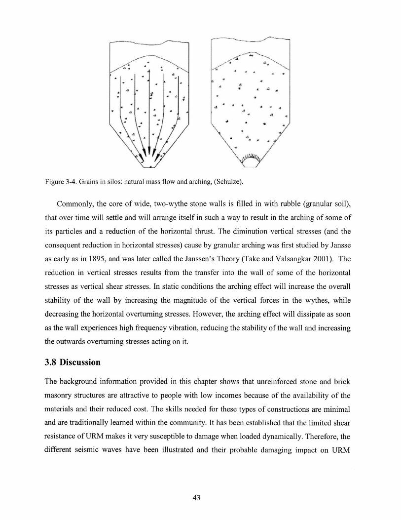
Figure 3-4. Grains in silos: natural mass flow and arching, (Schulze).
Commonly, the core of wide, two-wythe stone walls is filled in with rubble (granular soil),
that over time will settle and will arrange itself in such a way to result in the arching of some of
its particles and a reduction of the horizontal thrust. The diminution vertical stresses (and the
consequent reduction in horizontal stresses) cause by granular arching was first studied by Jansse
as early as in 1895, and was later called the Janssen's Theory (Take and Valsangkar 2001). The
reduction in vertical stresses results from the transfer into the wall of some of the horizontal
stresses as vertical shear stresses. In static conditions the arching effect will increase the overall
stability of the wall by increasing the magnitude of the vertical forces in the wythes, while
decreasing the horizontal overturning stresses. However, the arching effect will dissipate as soon
as the wall experiences high frequency vibration, reducing the stability of the wall and increasing
the outwards overturning stresses acting on it.
3.8 Discussion
The background information provided in this chapter shows that unreinforced stone and brick
masonry structures are attractive to people with low incomes because of the availability of the
materials and their reduced cost. The skills needed for these types of constructions are minimal
and are traditionally learned within the community. It has been established that the limited shear
resistance of URM makes it very susceptible to damage when loaded dynamically. Therefore, the
different seismic waves have been illustrated and their probable damaging impact on URM
structures described. Furthermore, the literature shows how shear fluidization, induced by high
frequency vibrations, can cause material ratcheting. Ratcheting, which results in cumulative
relative displacements between the stone units that make up a stone wall, can ultimately cause
wall crumbling. Finally, the literature also shows that high frequency vibrations can lead to the
compaction of granular soils and the diffusion of the arching phenomenon. This background
information will be used in the next two chapters: test methodology and analysis of results.

Chapter 4
4. Methodology4.1 Preliminary Evaluation
A number of different methods have been developed to evaluate the in-plane shear capacity
and out-of-plane behavior of unreinforced brick masonry. These methods, however, only
consider the two most common failure mechanisms occurring in brick masonry structures:
shear and overturning failure. Therefore, they cannot be implemented to study the behavior
of stone walls, where wall delamination and crumbling are two significant failure
mechanisms, or of two-wythe, infilled brick walls, where infill pressures can contribute to
the wall failure. Moreover, the traditional methods consider structural collapse as a
consequence of relatively large structural displacements and do not take into consideration
failures generated by high frequency vibrations, where displacements for each vibration
cycle are minimal.
Because the failure mechanisms of interest to this research are closely related to
geotechnical phenomena, it was decided to use the model for retaining walls of narrow
backfill width by Take and Valsangkar (2001) to calculate the pressures resulting from the
granular fill acting on the interior of the two wythes of the walls. This model includes the
reduction of horizontal stresses caused by the arching effect and is the most appropriate way
to predict and investigate the forces generated by the wall infill. In Figure 4-1 the non-linear
increase of the horizontal pressure with increasing depth is plotted for a granular material
(coal) with a density of 8.1 kN/m3 and a friction angle of 40 degrees.
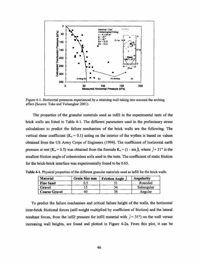
50
200S00
3250
IM
350
50 100 150 200Measured Horizontal Pressure (kPa)
Figure 4-1. Horizontal pressures experienced by a retaining wall taking into account the archingeffect (Source: Take and Valsangkar 2001).
The properties of the granular materials used as infill in the experimental tests of the
brick walls are listed in Table 4-1. The different parameters used in the preliminary stress
calculations to predict the failure mechanism of the brick walls are the following. The
vertical shear coefficient (Kv = 0.1) acting on the interior of the wythes is based on values
obtained from the US Army Corps of Engineers (1994). The coefficient of horizontal earth
pressure at rest (Ko = 0.5) was obtained from the formula Ko = (1 - sin)), where ) = 310 is the
smallest friction angle of cohesionless soils used in the tests. The coefficient of static friction
for the brick-brick interface was experimentally found to be 0.65.
Table 4-1. Physical properties of the different granular materials used as infill for the brick walls.
Material Grain Size mm Friction Angle AngularityFine Sand 0.5 31 RoundedGravel 15 34 SubangularCoarse Gravel 60 38 Angular
To predict the failure mechanism and critical failure height of the walls, the horizontal
inter-brick frictional forces (self-weight multiplied by coefficient of friction) and the lateral
resultant forces, from the infill pressure for infill material with ) = 310) on the wall versus
increasing wall heights, are found and plotted in Figure 4-2a. From this plot, it can be
0

observed that the resultant force of the internal pressure (solid line) remains smaller than the
resisting frictional forces (discontinuous line) beyond a height of 100cm, and therefore
sliding failure will not occur. In Figure 4-2b, the overturning moments caused by the
pressure acting on the wall (solid line) and the resisting moment, resulting from the self-
we:ight of the wythe and the shear forces transferred into the wythes from the granular infill
(discontinuous line) are again plotted versus increasing wall heights. This plot shows that
the critical wall height needed for the soil pressure to cause overturning failure of the wythes
is 160cm. From these two plots it can be concluded that the static failure mode would be by
overturning at a height of about 60cm. This height was then used as a reference to build the
first walls. The static failure height of the walls will vary, depending on the friction angle of
granular material used as infill.
Wall Height vs. Lateral ForceFriction Coefficient, mu=0.65
0 .100 900 1200 eo600F orce (N/(m of wall))
- -nil Pr"•..,mIk RARi•ultarnt
. Briuk Friutiuil FuruC
Wall Height vs. Moments ResultingFrom Soil Pressuire and SelfWeight
i nn
80
S4U
200
50 100Murritri (N'rri/rri uf wall)
- Murrieril Retulliriy Frurr Suil Prtusuru
-- - Moment Resulting From Self Weight
(a) Nb)
Figure 4-2. a) Wall height needed for sliding failure. b) Wall height needed for overturning failure,showing that a minimum wall height of 60cm is needed to cause overturning.
The prediction of the brick wall failure height under dynamic loading was difficult to
make, because there is no previous research available on the effect of granular infill on
masonry walls. Therefore, results from silo studies were used to approximate the changes in
internal stresses due to high frequency vibrations. The two major wall stress modifications
IUU
00
60
- '10
2n
0

were made to include the expected changes. First, the shear forces that were generated
between the wall and the granular material in the static case will be dissipated when the
infill is vibrated. Hence, there will be an increase in horizontal stresses on the wythes and a
reduction of the forces resisting their overturning. Second, the vibrations will cause the
granular infill to fluidize, resulting again in an increase of the horizontal pressure acting on
the wythes. For these two reasons the dynamic failure height was predicted to be at least
20% lower than the static. In addition, it is important to note that the failure mechanism
could change from overturning to sliding failure if a large enough vertical acceleration were
applied to the wall. The vertical acceleration would linearly reduce the frictional resisting
forces acting on the faces of the brick, hence reducing the overall resistance to sliding
failure.
No preliminary calculations were conducted to predict the failure height of the stone
specimens because, in this case, the overall dimensions of the walls were not considered a
determinant factor. However, the stone walls were considered to be a granular material made
up of large particles and they were expected to behave as such. As seen in Chapter 3, the
range of resonance frequencies of granular media starts at about 12Hz and therefore, inter-
stone vibrations were expected to become significant around this frequency, resulting in the
crumbling failure of the stone wall.
4.2 Static Tests: Brick Walls
The purpose of the static tests was to find the wall heights at which failure occurs due only
to the lateral pressure from granular infill materials with different friction angles. A standard
wall base length of 38cm and width of 27cm were used, and the failure height varied
depending on the infill friction angle. Cape Cod solid bricks (19.5x9x5.5cm) were used to
build the walls, with the lateral boundaries between the two wythes made of cardboard or
wood. The three types of granular infill had friction angles of 310, 340, and 380.
For the static tests, the walls were built row-by-row and simultaneously filled in, until
failure occurred. Numbering the bricks ensured consistency among the different walls. As
anticipated by the preliminary calculations, the walls failed at heights that ranged from 48cm
to 58cm, depending on the infill friction angle. That the experimental failure height was

consistently lower than the predicted one can be attributed to the irregularities in the shape
of the bricks, which lowered the overall stability of the walls, especially the ones
constructed in the earlier stages. Once the construction deficiencies were corrected, the
failure height ranged from 54cm to 58cm. Furthermore, all the walls failed by overturning,
as expected from the preliminary evaluations. No tests were conducted to find the static
failure height of the stone walls because of the greater static stability of the stone walls.
4.3 Dynamic Test: Brick and Stone Walls
The brick walls used in the dynamic tests were identical to the ones used in the static tests,
e:xcept that the heights were significantly reduced. The stone walls were built with
irregularly shaped stones to a height of 45cm. Numbering the individual stones (Figure
4-3b) ensured wall consistency. The dynamic testing program consisted of two distinct
testing phases: vertical and horizontal vibrations.
4.3.1 Vertical Vibrations
The first phase consisted of testing the walls dynamically on a vertically vibrating table with
a fixed frequency of 60Hz and variable acceleration. This frequency is higher than the
critical 15-25Hz resonant frequencies for granular soils (Massarsch 2005), which would
result in the maximum infill lateral pressure. However, by varying the vertical acceleration,
we were able to change the vibration intensity, and thereby investigate two significant
dynamic behaviors of unreinforced brick and stone walls. First, we evaluated the effect of
the increase of internal pressure on the two-wythe brick walls, resulting from infill
densification and shear fluidization by vertical vibrations. The lateral forces resulting from
internal pressures are particularly relevant in very old and historic buildings where the
unusually wide two-wythe walls are infilled with rubble. Second, the effect of high vibration
frequencies on .dry, undressed stone masonry, commonly used in low-cost housing, was
investigated. The testing procedure on the vertical vibrating table consisted in gradually
increasing the vibration magnitude (i.e., acceleration) until failure. Video recording of all the
tests allowed for time logging.

4.3.2 Horizontal Vibrations
In the second phase, the dynamic tests were conducted on a shake table with one horizontal
degree of freedom. As seismic waves always have vertical and horizontal components, both
brick (Figure 4-3a) and stone (Figure 4-3b) walls were tested under horizontal vibration to
complement the previously conducted vertical vibrations tests. The walls were set up on the
shake table in such a way that the motion would be applied along the plane of the walls. This
setup was used to isolate the effect on the wythes of the shear fluidization and densification
of the infill due to vibrations. If the vibrations had been induced perpendicular to the wall
plane, two additional overturning forces would have resulted from the dynamic loading: the
inertial forces of the wythes and the infill. The characteristics of the brick walls built on the
shake table were kept the same as the ones tested statically, except for the slight increase of
the brick width. This similarity allowed us to compare the static and dynamic failure
mechanisms and properties.
Two testing procedures were used. The first consisted of inducing a sinusoidal vibration
with variable frequency and a fixed maximum displacement. The wall was vibrated for two
minutes at a fixed frequency and the displacement was gradually increased to the maximum
desired. Then the vibration frequency was increased and held again for two minutes, while
the vibration displacement was gradually increased to the desired maximum. This step-wise
increase of frequency was repeated until the wall failed, which allowed us to identify the
frequency and acceleration at which the walls started to fail and fully failed. These
frequencies were then used in the second testing procedure, where the acceleration was
gradually increased while the frequency was kept constant. These tests allowed us to
confirm that high frequency / low energy vibrations could induce failure.

(a) (b)
Figure 4-3. a) Brick wall with transparent infill boundary; b) typical stone wall.
4.4 Analytical Models: Brick Walls
UDEC was used to model the brick and stone walls with granular infill. This software
allows taking a solid block and cutting it into multiple sub-blocks until the desired geometric
characteristics are replicated. The material properties of the masonry units and gravel used
in the construction of the physical specimens were mostly used in the analytical models with
little correction necessary. To ensure that the angle of repose of the modeled granular
material was similar to the actual one, a series of analyses were run by "pouring" the
modeled granular material onto a surface (Figure 4-4a). Then the angle of repose was
measured directly from the resulting graphical output of the analysis. The UDEC command
"voronoi," which randomly generates a series of cracks with an average pre-defined length
(Figure 4-4b), was initially used to model the granular infill. However, it was observed that,
depending on the degree to which the slopes of the cracks were aligned, the behavior or
resulting model could vary significantly. Therefore, to obtain a homogeneous infill with
fixed properties, the command "tunnel" was used to generate a granular infill made up of a
large number of circular cracks (Figure 4-4).

Figure 4-4. Gravel modeled with circular cracks: (a) before crumbling; (b) after crumbling, showingthe angle of repose.
The static test series included changes in the wall height and infill width, as well as
changes in infill friction angle. In the dynamic tests the wall height and infill friction angles
were changed. In addition, the importance of the loading frequency and maximum
acceleration were investigated. A sample of the scripts for the static and dynamic UDEC
models can be found in Annex 2.
4.5 Analytical Models: Stone Wall Delamination
As mentioned in Chapter 1, wall delamination is a commonly observed failure mechanism
of unreinforced stone masonry under seismic loading. Models illustrating this failure
mechanism are shown in Figure 4-5.

(a) (b) (c) (d)
Figure 4-5. Wall delamination process.
The analytical models used to investigate the behavior of such walls consisted in two
parallel wythes of stones with granular material as infill (Figure 4-6a). The material
properties and dimensions of all the models analyzed were kept constant. The only change
made to the model was the insertion of two and four through-stones to investigate their
effectiveness in preventing wall delamination (Figure 4-6b). The loading accelerations were
increased until failure of the model.

Figure 4-6.(a) Stone wall model; (b) model with through-stones.
4.6 Discussion
Take and Valsangkar (2001) have developed a model for retaining walls of narrow backfill
width to calculate the pressures resulting from the granular fill acting on the interior of a
retaining wall. This method was used for the preliminary analysis of the static behavior of
the two-wythe brick walls with infill. This model shows a non-linear increase of the lateral
pressures with depth due to the arching phenomenon, which predicted a static failure by
overturning at a height of 60cm. The static failure of the physical models occurred, as
predicted, by overturning. However, the failure height was consistently lower (average of
56cm) than predicted, mainly due to the irregularities in the bricks.
For the dynamic testing of the physical models, both horizontal and vertical vibrations
were investigated at different frequencies and accelerations. Finally, the analytical models
were used to investigate a large number of model variations, including wall height and
width, and infill properties, for the static case. In the dynamic tests, the model height, the
infill properties, and the loading frequency and accelerations were varied.

Finally, the problem of wall delamination of unreinforced stone walls and the commonly
used through stone solution to this failure mechanism were modeled and investigated.

Chapter 5
5. Results5.1 Static Tests: Brick Walls
Results from the eleven static tests indicate that the static infill pressure on the two wythes is
significant enough to contribute to the damage of a wall. Overturning was the common failure
mechanism and the size of granular infill was the main factor that influenced the failure height of
the wall.
5.1.1 Influence of Granular Infill Friction Angle
The infill column height (i.e. wall height) needed for overturning failure increased with the
increasing infill material friction angle (A, which is consistent with the fact that larger friction
angles cause a smaller lateral pressure. Figure 5-1 correlates the material's friction angles and the
average wall failure height. The failure heights vary from 48cm for )=3 10 to 58cm for )=380,
which represents a 20% increase in failure height.
Figure 5-1. Effect of friction angle on failure height: increasing friction angle results in an increase of thewall failure height.
Friction Angle vs. Static Failure Height
M Physical Tests E Analytical Models70 -60 -
E.2- 50 -
40-
I 30-
. 20-LL 1 0 -
0-o=310 0=340 0=380
Friction Angle
I- - -
1
I
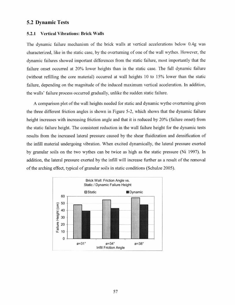
5.2 Dynamic Tests
5.2.1 Vertical Vibrations: Brick Walls
The dynamic failure mechanism of the brick walls at vertical accelerations below 0.4g was
characterized, like in the static case, by the overturning of one of the wall wythes. However, the
dynamic failures showed important differences from the static failure, most importantly that the
failure onset occurred at 20% lower heights than in the static case. The full dynamic failure
(without refilling the core material) occurred at wall heights 10 to 15% lower than the static
failure, depending on the magnitude of the induced maximum vertical acceleration. In addition,
the walls' failure process occurred gradually, unlike the sudden static failure.
A comparison plot of the wall heights needed for static and dynamic wythe overturning given
the three different friction angles is shown in Figure 5-2, which shows that the dynamic failure
height increases with increasing friction angle and that it is reduced by 20% (failure onset) from
the static failure height. The consistent reduction in the wall failure height for the dynamic tests
results from the increased lateral pressure caused by the shear fluidization and densification of
the infill material undergoing vibration. When excited dynamically, the lateral pressure exerted
by granular soils on the two wythes can be twice as high as the static pressure (Ni 1997). In
addition, the lateral pressure exerted by the infill will increase further as a result of the removal
of the arching effect, typical of granular soils in static conditions (Schulze 2005).
0=31 0=340 0=380Infill Friction Angle
Brick Wall: Friction Angle vs.Static / Dynamic Failure Height
0 Static E Dynamicu6 -
p50 -E
u 40 --0-a) 30 -
0-
-- -~- I -I
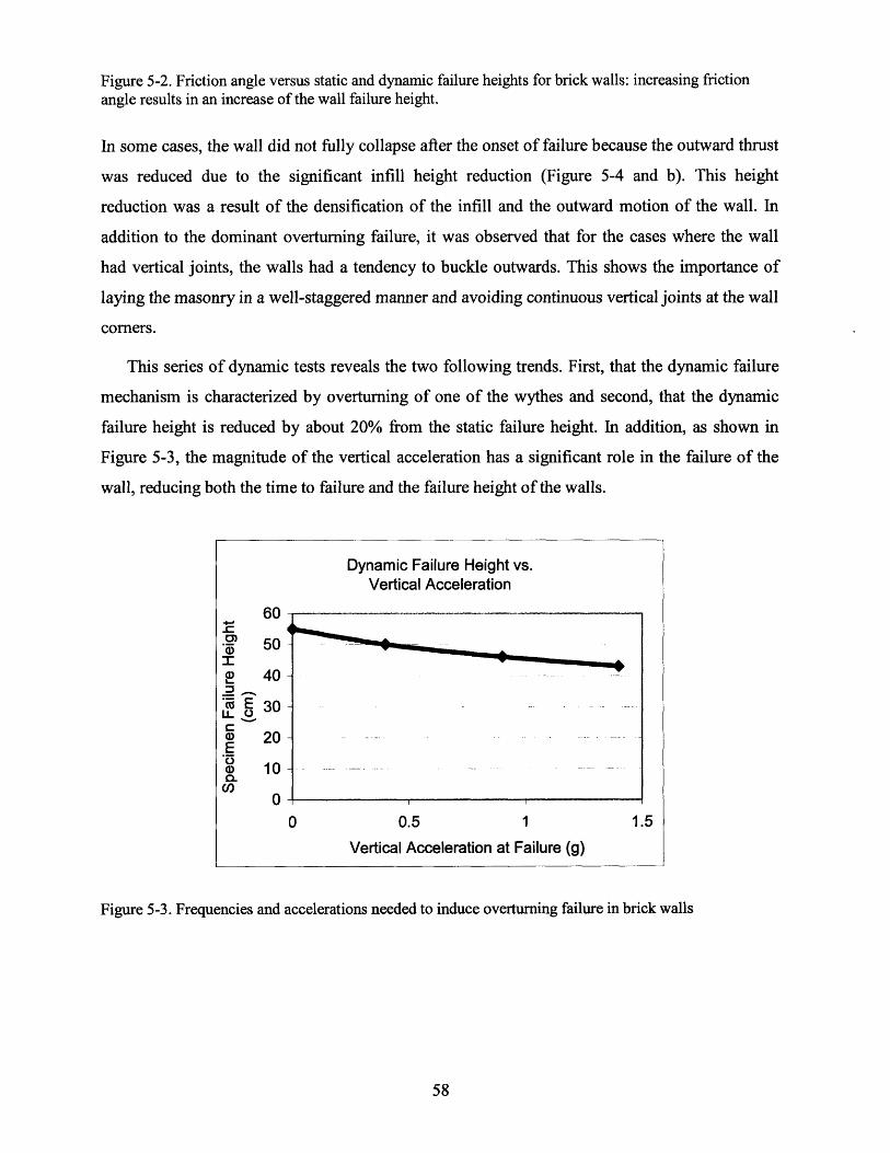
Figure 5-2. Friction angle versus static and dynamic failure heights for brick walls: increasing frictionangle results in an increase of the wall failure height.
In some cases, the wall did not fully collapse after the onset of failure because the outward thrust
was reduced due to the significant infill height reduction (Figure 5-4 and b). This height
reduction was a result of the densification of the infill and the outward motion of the wall. In
addition to the dominant overturning failure, it was observed that for the cases where the wall
had vertical joints, the walls had a tendency to buckle outwards. This shows the importance of
laying the masonry in a well-staggered manner and avoiding continuous vertical joints at the wall
corners.
This series of dynamic tests reveals the two following trends. First, that the dynamic failure
mechanism is characterized by overturning of one of the wythes and second, that the dynamic
failure height is reduced by about 20% from the static failure height. In addition, as shown in
Figure 5-3, the magnitude of the vertical acceleration has a significant role in the failure of the
wall, reducing both the time to failure and the failure height of the walls.
Figure 5-3. Frequencies and accelerations needed to induce overturning failure in brick walls
Dynamic Failure Height vs.Vertical Acceleration
50 -
2 40-
' E 30 -
Cu 20-E(D 10-
0-0 0.5 1 1.5
Vertical Acceleration at Failure (g)

5.2.2 Horizontal Vibrations: Brick Walls
The brick dimensions used to build the walls on the shake table were different from the ones
used in the vertical vibration tests. Therefore, a series of five static tests were conducted to find
the average static failure height of 67cm. Two different wall heights were tested dynamically and
found to fail at 37cm and 45cm respectively, which represent a 44 percent and 33 percent
reduction from the average static failure height of 67cm. The static safety factors' for the
dynamically tested walls were 1.4 and 1.3 respectively. The failure mechanism observed during
the dynamic tests consisted of three distinct stages: infill densification, shear fluidization causing
significant wall deformation, and wall failure. Table 5-1 shows a summary of the frequencies and
minimum accelerations needed for these three stages to occur.
Table 5-1. Frequencies and minimum accelerations needed for the three failure stages to occur.
Failure Mechanism Frequency (Hz) Min. Acceleration (g)Infill Densification 7 0.17Shear Fluidization 9-20 0.2Major Wall Deformation 9-20 0.3
The failure mechanism was initiated at an approximate frequency of 7Hz and accelerations
not larger than 0.17g. At these frequencies, the granular infill densified and the arching effect
was lost, resulting in an increase of lateral pressure on the two wall wythes. This densification
continued for a short period of time and then the infill stabilized (Figure 5-4a). Infill
densification resulted in a reduction of infill height, which in turn reduced the overturning
moment caused by the internal pressure, and a slight outwards motion of the wythes (failure
onset). In the cases where the infill was replenished, the wall failed without having to increase
either the vibration frequencies or the acceleration.
The second failure stage occurred at frequencies between 9-20Hz and accelerations not larger
than 0.2g. In this range of frequencies the granular infill underwent both densification and shear
fluidization (Figure 5-4b). The shear fluidization of the infill sharply increased the lateral
pressure on the two leaves, pushing them farther away.
The third failure stage occurred when frequencies between 9-20Hz were applied and the
maximum acceleration was increased to about 0.3g. Under these conditions, the wall failed in
'Static safety factor = (Resisting Moment / Overturning Moment)
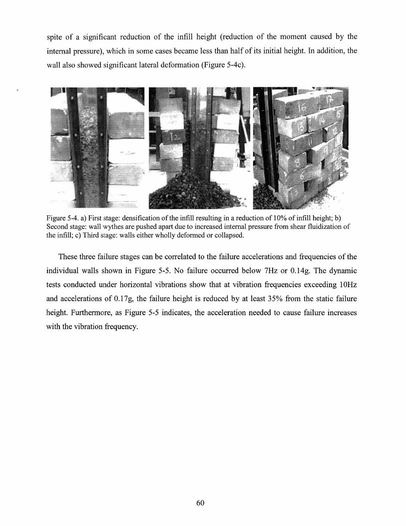
spite of a significant reduction of the infill height (reduction of the moment caused by the
internal pressure), which in some cases became less than half of its initial height. In addition, the
wall also showed significant lateral deformation (Figure 5-4c).
Figure 5-4. a) First stage: densification of the infill resulting in a reduction of 10% of infill height; b)Second stage: wall wythes are pushed apart due to increased internal pressure from shear fluidization ofthe infill; c) Third stage: walls either wholly deformed or collapsed.
These three failure stages can be correlated to the failure accelerations and frequencies of the
individual walls shown in Figure 5-5. No failure occurred below 7Hz or 0.14g. The dynamic
tests conducted under horizontal vibrations show that at vibration frequencies exceeding 10Hz
and accelerations of 0.17g, the failure height is reduced by at least 35% from the static failure
height. Furthermore, as Figure 5-5 indicates, the acceleration needed to cause failure increases
with the vibration frequency.

Brick Specimen: Failure Frequency andHorizontal Acceleration
0.35
0.3
0.25
0.2
0.15
0.1
0.05
0
Figure 5-5. Frequencies and accelerations needed to cause full failure of the brick walls.
5.2.3 Horizontal Vibrations: Stone Walls
The results of the four dynamic tests show that the failure of the stone walls is dependent on
vibration frequency, acceleration, and vibration time. In Table 5-2, a typical variable frequency
testing procedure for stone wall #2 is shown. The first dynamic failure occurs at a vibration
frequency of 11Hz and an acceleration of 0.17g and the final failure occurs at 15Hz and 0.28g.
The damage of the wall progressed with time.
Table 5-2. Testing procedure for variable frequencies and maximumsequence was held for two minutes (2ndstone wall).
Frequency Hz Acceleration g Comments7 0.11 Stable9 0.12 Stone dislocations11 0.17 1st failure13 0.12 Gravel flow13 0.19 Gravel flow15 0.28 2
*d failure17 0.29 Moving stones19 0.38 Moving stones
accelerations. Each
The test results (Figure 5-6) indicate that a minimum horizontal vibration frequency of 11Hz
and horizontal acceleration of 0.1 8g was needed to cause dislocation of the stones. That one wall
I I
10 15Failure Frequency (Hz)
1

failed at the same frequency, but at the much higher acceleration of 0.36g, can be attributed to
the difference in construction quality. To test the walls' response at high vibration frequencies,
two walls were tested to failure at a constant frequency of 20Hz. The walls failed at 0.25g and
0.5g. As in the case of the brick walls, the experimental evidence shows that the acceleration
causing failure increases with increasing frequency.
Figure 5-6. Failure frequencies and accelerations for stone walls.
Finally, it was observed that the vibration time proved to significantly influence the failure
when the minimum failure frequencies and acceleration of 11Hz and 0.18g were exceeded. It
was observed that the movement of the walls progressed with time, even when the frequency and
acceleration were constant.
5.3 Analytical Model
5.3.1 Static Conditions
UDEC was used to simulate the static failure of the brick walls. The block and infill friction
angles used in the model were the same as those used in the preliminary calculations. The coarse
gravel-sized material (with )=380) was used as the basic infill for the model as seen in Figure
5-7a.
The failure mechanism obtained using the analytical model was almost identical to the failure
mechanism of the physical walls, with a failure onset quickly followed by the overturning of the
Failure Frequency and AccelerationStone Specimen
0.6
c 0.50
.c 0.4
0.3
< 0.2
M2 0.10
-0 5 10 15 20 25
Failure Frequency (Hz)

wythes (Figure 5-7b and c). The failure height of the UDEC model was consistently higher than
the failure height of the physical models. This height difference can be explained by the fact that
the bricks used in the experiments were not perfectly rectangular, allowing for some initial out-
of-plane movement of the wall wythes and reducing the overall stability of the wall.
It must be kept in mind that the failure height of the analytical model, as it was the case in the
physical wall specimens, represents the height of the wythes and the initial granular infill height.
The actual infill height will be significantly reduced, up to 50% from the initial height, due to
spreading and overturning of the wythes. If the infill height were to be kept constant (by refilling
the core space during the test) the failure heights would be lower and the difference between the
static and dynamic failure height would be much larger. To overcome this difficulty, the initial
outwards movement of the wythes, or failure onset, could be used as a reference to identify the
failure of the model.
(a) (b) (c)Figure 5-7. The UDEC static model with coarse gravel-sized infill material, a) Initial state of the modeljust after applying the gravitational force to the model; b) Failure onset after two seconds; c) Failed stateafter four seconds.
5.3.1.1 Variations in Infill Properties / Friction Angle
An analytical model with a brick and infill width of 15cm and varying height was used to
investigate how the friction angle of the granular infill influences the lateral pressure exerted by
the infill on the interior of the wythes. To ensure full consistency of the different models, the
infill material was modeled as circular units of constant diameter instead of the previously used

randomly generated core material (Figure 5-8a). The friction angle was set to a value and models
of different height were used to identify the height at which the model was about to fail for a
given friction angle. Then the friction angle was increased and the impending failure height was
found again.
The change in impending failure height for different friction angles is shown in Figure 5-8a.
Between 55 and 85cm, the model showed a slow increase in the friction angle needed to keep the
model stable when the wall height was increased. Then, between 85 and 115 the friction angle
had to be increase much faster with increasing model heights. Beyond a height of 115cm, the
model failed independently of the friction angle of the infill.
(a)
Figure 5-8. a) Plot of the impending failure height of the model given different friction angles of the infillmaterial; b) Analytical model used with circular infill.
5.3.1.2 Variations in Wall Width
To investigate the effect of increasing the wall's core width (Figure 5-10), a model with a
constant height of 90cm was used. Then the width was increased and multiple analyses were run
using different friction angles for the core material until the largest that would cause failure of
the model was identified.
The plot in Figure 5-9 shows how a slow increase in the granular infill friction angle is
needed to keep the model stable for an increase in infill width between 5 and 25cm. However,
Friction Angle vs.Impending Failure Height
--4-Impending Failure Height.4, .4 t'•
IIU -
E 100 -
90-80-70 -60-
50 -40
0 20 40 60Friction Angle (degrees)
^`~~"^""~~~"~L^~~"~"~I";'YYI~`Y~~-~YI-- I
.. I I

beyond a width of 25cm, the friction angle has to be increased much faster with an increasing
infill width. Furthermore, at infill width larger than 35cm the model failed irrespective of the
infill's friction angle.
The failure mechanisms observed between infill widths 5-25cm consisted in initial outwards
sliding of the block units, followed by the overturning of one or both wythes. The sliding became
increasingly significant with an increasing infill width. The model with an infill width of 30cm
failed by outward sliding of the two wythes (Figure 5-11).
Figure 5-9. Plot of the infill material's friction angle needed to allow for a given infill width to be stable.A 90cm high model was used in all analyses.
Figure 5-10. Models with constant height and varying infill width.
Friction Angle vs. Infill Width at Failure
-4-Width35
S30-2o 25 -
20 -15-
= 10-. 5
0 - I I0 20 40 60 80
Friction Angle (degrees)
1
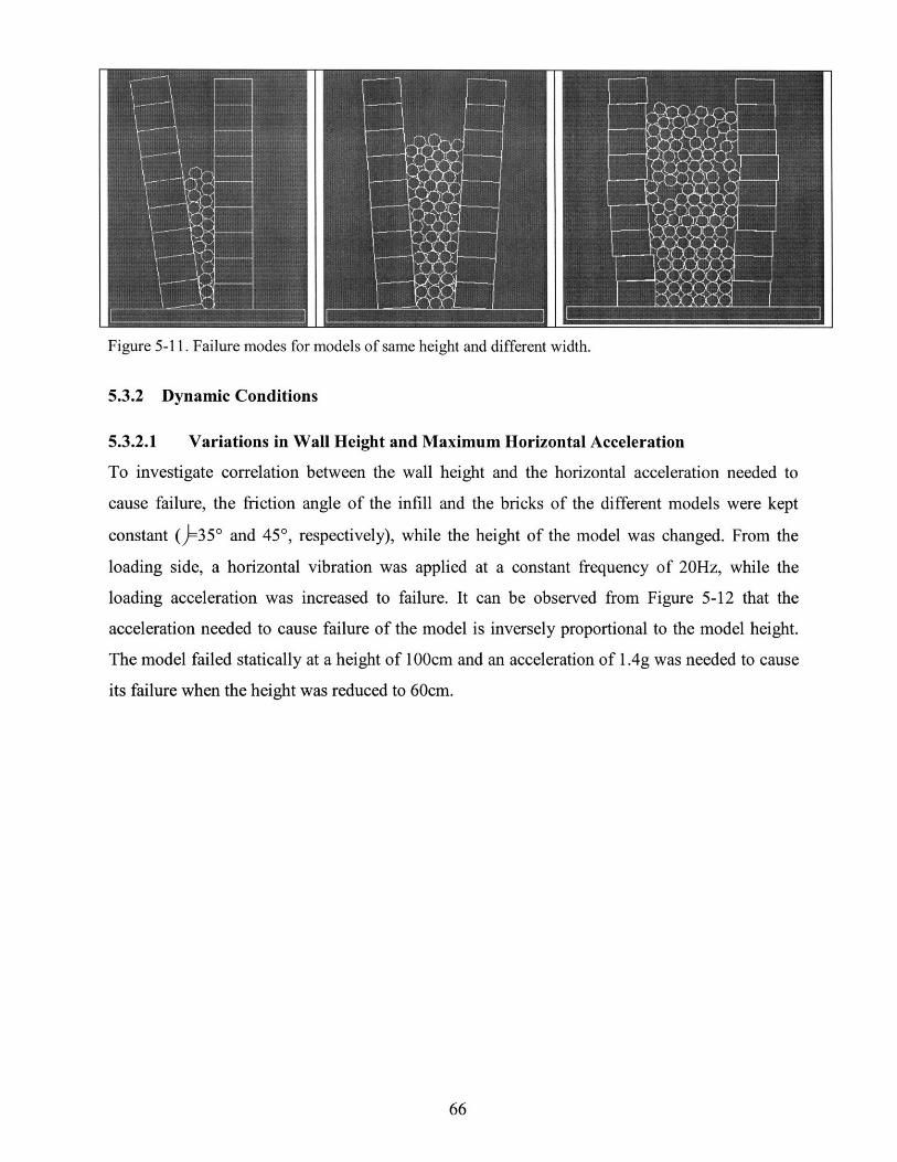
Figure 5-11. Failure modes for models of same height and different width.
5.3.2 Dynamic Conditions
5.3.2.1 Variations in Wall Height and Maximum Horizontal Acceleration
To investigate correlation between the wall height and the horizontal acceleration needed to
cause failure, the friction angle of the infill and the bricks of the different models were kept
constant (=350 and 450, respectively), while the height of the model was changed. From the
loading side, a horizontal vibration was applied at a constant frequency of 20Hz, while the
loading acceleration was increased to failure. It can be observed from Figure 5-12 that the
acceleration needed to cause failure of the model is inversely proportional to the model height.
The model failed statically at a height of 100cm and an acceleration of 1.4g was needed to cause
its failure when the height was reduced to 60cm.

Horizontal Acceleration / Model Failure HeightBrick 0=450; Infill 0=350
ILU
E 100480-
60-
40-
o 20-0
0 0.5 1 1.5
Acceleration (g)
Figure 5-12. Horizontal acceleration needed to cause the failure with decreasing model heights.
5.3.2.2 Variations in Wall Height and Maximum Vertical Acceleration
As in the previous section, to study the correlation between the wall height and the vertical
acceleration needed to cause failure the friction angle of the infill and the bricks of the different
models were kept constant ()=350 and 450, respectively), while the model height and the loading
acceleration were changed. The vertical vibration was applied at a constant frequency of 20Hz,
while the loading acceleration was increased to failure. It can be observed from Figure 5-13 that,
as it was the case for horizontal acceleration, the vertical acceleration needed to cause failure of
the model decreases with increasing model height. However, it is interesting to note that the
vertical accelerations at failure are consistently lower than the horizontal accelerations needed to
cause the failure of the model. This shows the importance of taking into account the vertical
component of the seismic vibrations during the structural design process.
..... --. ...I

Vertical Acceleration / Model Failure HeightBrick 0=450; Infill o=350
4 ,rt"
0 0.2 0.4 0.6 0.8 1
Acceleration (g)
Figure 5-13. Vertical acceleration needed to cause the failure with decreasing model heights.
One example representative of the difference in behavior of the models subjected to
individual 20Hz vertical or horizontal vibrations is the case of the 60cm high wall model seen in
Figure 5-15a and b. This model failed at a maximum acceleration of 0.5g when vibrated
vertically, while it did not fail even at accelerations over 1.7g (much higher than encounter in
real life) when vibrated horizontally. Moreover, the failure mode of the model subjected to
vertical vibrations was mainly through sliding of the different blocks.
5.3.2.3 Simultaneous Vertical and Horizontal Vibrations
When simultaneous horizontal and vertical vibrations were induced, it was observed that the
sliding of the blocks and subsequent failure occurred at smaller loading accelerations. Examples
of this failure behavior were the 60cm high models shown in Figure 5-15 that were both vibrated
at 20Hz and with an acceleration of 0.8g. The model in Figure 5-15a was excited in both vertical
and horizontal directions, while the model in Figure 5-15b was only vibrated in the horizontal
direction. The model vibrated in both directions fully failed, while the other model remained
stable after an initial overturning motion.
.I I ..
I0V -
.100
. 80 -'FD 60I 40-0 20o2 0-

Figure 5-14. Plot showing the maximum acceleration needed to cause failure of a specimen of a givenheight.
(b)
Figure 5-15. a) Model failing through sliding of the bricks; b) Model after initial rotation of the wythes.
5.3.2.4 Wall Delamination and Through-Stones
The model with no through-stones (Figure 5-16a) failed by delamination at an acceleration of
0.19g, while neither of the other two models, which had two and four through-stones inserted
(Figure 5-16b and c), failed at this acceleration. The models that had two and four through-stones
inserted failed at accelerations of 0.32g and 0.45g, respectively.
Maximum Acceleration vs. Failure Height
-+-Vertical Horizontal * Horizontal & Vertical
IZU
100
80S60
*a 4020
0
0 0.5 1 1.5
Maximum Acceleration (g)

(b)
Figure 5-16. (a) Model of two-wythe stone walls without through-stones; (b) Model with two through-stones; (c) Model with four through-stones.
As can be observed in Figure 5-17a, the failure of the model with no through-stones did notonly fail at a significantly lower loading acceleration, but it also failed in a catastrophic manner,dissipating only limited energy during the failure process. The models with through-stones(Figure 5-17b and c) deformed significantly before fully failing. This shows that the use ofthrough-stones will provide much needed ductility in seismic events to unreinforced stonemasonry structures.
(b)
Figure 5-17. (a) Failure at 0.19g; (b) Failure at 0.32g; (c) Failure at 0.45g.
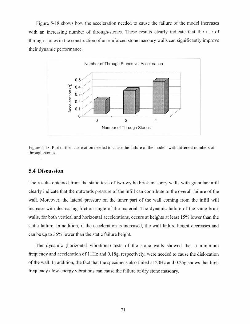
Figure 5-18 shows how the acceleration needed to cause the failure of the model increases
with an increasing number of through-stones. These results clearly indicate that the use of
through-stones in the construction of unreinforced stone masonry walls can significantly improve
their dynamic performance.
IumI~: er o roIugI 3L~tone vs. ncIceera onlV
0
o4WL
'I)0
oo<
0 2 4
Number of Through Stones
Figure 5-18. Plot of the acceleration needed to cause the failure of the models with different numbers ofthrough-stones.
5.4 Discussion
The results obtained from the static tests of two-wythe brick masonry walls with granular infill
clearly indicate that the outwards pressure of the infill can contribute to the overall failure of the
wall. Moreover, the lateral pressure on the inner part of the wall coming from the infill will
increase with decreasing friction angle of the material. The dynamic failure of the same brick
walls, for both vertical and horizontal accelerations, occurs at heights at least 15% lower than the
static failure. In addition, if the acceleration is increased, the wall failure height decreases and
can be up to 35% lower than the static failure height.
The dynamic (horizontal vibrations) tests of the stone walls showed that a minimum
frequency and acceleration of 11Hz and 0. 18g, respectively, were needed to cause the dislocation
of the wall. In addition, the fact that the specimens also failed at 20Hz and 0.25g shows that high
frequency / low-energy vibrations can cause the failure of dry stone masonry.
N b f Th h S
A l ti

The static tests of analytical models of the walls confirm that a reduction in friction angle of
the infill will also result in a reduction of the failure height. The only difference between the
physical and analytical tests being that the failure height of the model was increased by 5-10%.
Additional results also showed that an increase in infill width results in an increase of the internal
normal pressure on the wythes, and therefore, a reduction in failure height. This is probably due
to a reduction of the significance of the arching effect and vertical shear force on the walls
coming from the infill. For the case of dynamic loading, the analyses indicate that vertical
vibrations are more detrimental than horizontal ones, and that it is the combination of vertical
and horizontal vibrations that cause the models to fail at the lowest loading accelerations. In
addition, the problem of wall delamination was investigated. The results clearly indicate that the
introduction of through-stones will increase the stability and ductility of the wall.
Finally, these series of empirical and analytical tests show that high frequency / low energy
seismic vibrations can be significant enough to cause failure of an unreinforced masonry
structure.

Chapter 6
6. Low-Cost Remedial ActionsThis chapter describes a series of low-cost, low-tech remedial actions that can make a significant
difference in the seismic performance of both unreinforced brick and stone masonry. It is
important to note that the objective of these construction improvements is only to provide those
with no or very limited economic resources with the means of reducing the damage to their
houses and the harm to their dwellers. However, these strengthening methods will not make the
structures "earthquake-proof' because of the inherent structural limitations of unreinforced
masonry under seismic loads. Construction improvements for new construction and retrofit
methods for existing buildings will be considered.
6.1 New Construction
After recent catastrophic earthquakes it might be assumed that the construction practices in new
structures would discard previous obviously inadequate construction practices. This, however, is
not the case in developing countries, where most of the unreinforced, poorly built structures are
located. The author has visited several regions-Izmir, Gujarat, Bam, Lijiang-in the aftermath
of major earthquakes and has consistently observed that, in the cases where URM was still used,
the construction practices neglect to integrate the basic improvements needed to build stronger
structures. Some of these low-cost improvements are described in the next sections.
6.1.1 Through-Stones and Stone Shape
The introduction of through-stones is the most effective solution to the extremely common
problem of wall delamination (Figure 6-2a and b). This solution has been proposed by Murthy
(2003), among others, and is well known among the experts in URM. However, it seems that it
has yet to reach the people who need to implement this technique. Besides preventing wall
delamination, through-stones could also significantly slow down the wall disaggregation process
resulting from shear fluidification.

Figure 6-1. (a) Delamination of a dry stone wall with no through-stones; (b) through-stone solution.
As seen in Figure 6-2a, the introduction of through-stones in the wall has to be done at
horizontal and vertical staggered intervals of minimum 50cm and 70cm, respectively. It is
preferable that large, long stones be used to ensure proper connection of the two wall wythes. In
the event that long enough stones are not available, a combination of four smaller stones can be
used to achieve the same effect (Figure 6-2b).
The shape of the stones is one of the key issues in building a safe stone house. It is very
important to use cubical and rectangular stones of similar size and to avoid oblong, rounded, and
small stones. The stone shape and size are crucial in the comers, where it must be ensured that
large rectangular stones are used and are laid alternating the long sides, as seen in Figure 6-2a.
70cm
70cm
1"J
50cm 50cm (a)
Figure 6-2. (a) Wall corner with through-stones and big, uniform corner stones; (b) through stone madewith four units of smaller stones.
I Ii

6.1.2 Distribution and Proportions of Openings
The overall stability of the structure can also be improved by following the appropriate opening
proportions and distribution. Commonly accepted opening proportions can be found in Figure
6-3, which can vary depending on the quality of the construction and the size and shape of the
stones used. By respecting these dimensions crack initiation and propagation in unreinforced
stone houses will be significantly reduced.
The distribution of the openings around the house is also to be taken into account when
deciding where to position them, because an inappropriate distribution could result in torsional
forces on the structure. Therefore, it should be ensured that the overall center of stiffness of the
house be kept close to its center of mass.
Figure 6-3. Recommended opening proportions for a one-story, unreinforced stone house (Source: Arya2005).
6.1.3 "Hanchiku" Seismic Base Isolation
A method of building earthen foundations using alternated layers of loose sand and fat clay was
introduced to Japan from China fifteen centuries ago (http://www.aisf.or.jp/-jaanus/deta/
Desirable Opening Sizes 1
B4>(0.5)H2 , and >60cmB5>(0.25)H1 , and >60cmH3 >60cm or >(0.5)B2 or B8 (choose largest)

h/hanchiku.htm). This same method was then used as a base isolator for temples and other
important structures. "Under the building to be protected, a cushion of fat clay with enclosed
loose sand layers is placed and kept water-saturated. Base shaking by a strong earthquake leads
to degradation of shear stiffness in the first cycle so that further shear waves cannot reach the
building," as seen in Figure 6-4 (Gudehus 2004).
Figure 6-4. "Temples in Kyoto with Hanchiku seismic isolation. The inlets show confining seal of chalkyclay and base rocks to keep settlements at acceptable limits." (Source: Gudehus 2004)
The Hanchiku seismic isolation principle could be implemented in low-cost housing too. One
way proposed by Gudehus (personal conversation) is to align a series of old tires at the
foundation level and fill them with a layer of fat clay, a layer of loose sand, and again a layer of
fat clay. This way the desired base isolation can be achieved without a major investment. The
drawback of this system is that the saturation of the sand layer must be continuously maintained;
otherwise, it will not perform adequately.
An additional low-cost base isolation system, still to be investigated, is the mixing of rubber
pieces (from old tires, for example) with the stones that make up the foundations. By mixing
rubber pieces, in a stone/rubber volume ratio to be determined, the high frequencies (above
10Hz) seismic vibrations could be significantly filtered out, and thereby preventing the damage
caused by the previously described shear fluidization. This foundation system, however, will not
isolate the structure from lower frequencies, which can be the source of major structural damage.

6.2 Retrofit
A structurally deficient house can be retrofitted by introducing a number of structural upgrades
that will improve its performance during an earthquake. However, it is important to first assess
the adequacy of the overall structural strength to ensure that it is worth upgrading. The seismic
performance of a seriously deficient structure will only be marginally improved by retrofitting it
because the improvements will ultimately not be engaged during a seismic event. Therefore, the
owners should be informed of the risk and advised to demolish and rebuild it. Retrofit of a
severely deficient house will only mislead its dwellers into believing that they will be safe in it in
the event of an earthquake.
There is no one-for-all type of retrofit method. The choice of the retrofit system used will
depend on the type of structural deficiency, the materials used in the structure, the availability
and cost of construction materials, the available construction skills, and the cost that the
homeowners are willing to pay for the improvement. Only simple, low-cost retrofit methods for
unreinforced stone masonry houses are considered in the next section, including through-stones,
cementicious mortar, partition of long rooms, and roof-wall connection systems. These retrofit
methods are commonly found in the literature concerned with the retrofit of low cost housing,
however, the two roof-wall connection systems presented here have yet to be tested empirically
to asses their performance.
6.2.1 Through-Stones and Cementicious Mortar
The simplest and cheapest solution to prevent two major failure mechanisms in unreinforced
stone masonry, wall delamination and crumbling, is to replace some of the stones that make up
the individual wythes by through-stones. This will be achieved by carefully removing a stone (or
more, if needed) at the same height on each side of the wall, which will leave an open cavity
across the wall. The stones to be replaced should preferably be small. Then, a stone of a length
at least equal to the wall width and with volume similar to the cavity is to be placed in the cavity
and laid in a cementicious mortar. As mentioned earlier, the through-stones should be spaced at
less than one meter horizontally and seventy centimeters vertically; in addition, the different
horizontal rows should be staggered with respect to each other. In the event that large enough
stones are not available, a concrete block or steel hook can be used instead. In this case, it is key
to ensure that the cavity is fully grouted with cement mortar.

In a many low-cost stone houses, the stones were laid in mud mortar (Figure 6-5a), which
will easily crumble when vibrated, leaving large voids around the stones (Figure 6-5b) and
inducing wall crumbling. Ideally, the mud mortar should be removed as far as the available tools
can reach into the wall, and then replaced by a cementicious mortar, to prevent further wall
delamination and crumbling.
(a) (b)
Figure 6-5. (a) Stone laid in thick mud mortar; (b) dry mud mortar falling out of the joints leaving voidsaround the stone units.
6.2.2 Room Partitions
The out-of-plane wall failure is a commonly occurring failure mechanism in URM. The
individual walls of an unbound structure act independently of each other and, therefore, are very
weak in resisting loads perpendicular to their planes. This is particularly true in the case of long
continuous walls, as shown in Figure 6-6.

Figure 6-6. Out-of-plane failure of a long, continuous wall.
The ideal solution for such long continuous walls is to introduce partition walls to supply
restraint. If there are no restrictions, the proportions of the partitions that should ideally be
achieved are the ones shown in Figure 6-7, where a/t < 40.
Figure 6-7. Introduction of cross-wall to improve the out-of-plane behavior.
Introducing cross-walls is often not possible, or is insufficient to prevent out-of-plane failure,
particularly in the case of dry stone masonry. In such situations, it is necessary to introduce a
retrofit system that, by structurally connecting them, will transform the individual actions of the
four walls into a box action. This can be achieved by taking advantage of the roofing structural
system, that more often than not consists of trusses or robust beams. The two retrofit systems
proposed next were developed for the region of Kashmir, Pakistan, taking into account that the
cost as well as the skills needed for the implementation should be kept to a minimum.
6.2.3 Roof-Wall Connection I
The first system proposed consists of a series of dowels (wood or steel) being inserted into the
wall. Then, a wire is attached at one end of the dowel and run over the roofing structural member
running along the top of the wall and then down the other side of the wall, tying it to the other
end of the dowel (Figure 6-8). By interconnecting the walls through the roofing members a box
effect can be achieved. An additional benefit of this retrofit system is that the effect of a ring
beam can be obtained by post-stressing the top part of the wall with the wires. For this system to

perform adequately, the stiffness of the roof has to be large enough to allow for the load transfer.
The roof stiffness should be improved if it is too small.
Wir
Figure 6-8. Roof-wall connection system using dowels and wires (Drawings by: Yanni Loukissas).
6.2.4 Roof-Wall Connection II
The second roof-wall system proposed, which is particularly indicated for low quality dry stone
masonry (where the stones used are small and the joints large), is the use of timber members to
interconnect the different walls through the roofing system while holding the walls in place
(Figure 6-9).

Add t o a t iber m e mbe
on both sides of the wat!
Figure 6-9. Roof-wall connection system using timber members (Drawings by: Yanni Loukissas).
6.3 Discussion
The first part of this chapter discussed a number of low-cost construction improvements that can
be used in new unreinforced stone masonry structures. The introduction of through-stones and
the use of large rectangular stones is the most efficient way to prevent two commonly occurring
failure mechanisms, wall delamination and crumbling. Also, the importance of the proper
dimensioning and distribution of wall openings has been described and a table with the proper
opening dimensions provided. In addition, it has been explained that it is important to keep the
centers of mass and stiffness of the structure close to each other to prevent the generation of
torsional forces. This can be achieved by evenly distributing the openings around the structures.
In addition, a series of retrofit systems have been described that can be used to strengthen
existing structures. Finally, a possible low-cost implementation of "Hanchiku," an ancient
Chinese base isolation system, has been suggested as a foundation system with isolation
properties. A simpler but as yet untested high frequency filter obtained by introducing rubber
pieces at the foundation level, has been proposed to provide a simple, low-cost limited base
isolation.

A number of simple retrofit systems for unreinforced stone masonry have been suggested in
the second part of this chapter. As for new construction, the insertion in the walls of through-
stones is an efficient and cost-effective way to strengthen two-wythe walls. Furthermore, to
reduce the risk of out-of-plane failure of long unsupported walls, the construction of partition
walls has been recommended. Finally, two wall-roof connection arrangements have been
provided for bonding together the individual walls and achieving an overall box behavior of the
structure.

Chapter 7
7. Conclusions and Future Work
This preliminary research has shown that, in spite of having a small energy content and being far
from the natural frequencies of structures, the high frequency components of earthquake
vibrations can be the source of significant structural damage to unreinforced masonry. Moreover,
our tests have proven that the higher frequency waves travelling through stiff masonry structures
can trigger two types of failure mechanisms that have not yet been taken into account.
The first failure mechanism is associated with the fact that high frequencies can cause small
vertical inter-stone vibrations that result in irreversible relative displacements (racheting) of the
stones, causing the wall to deform and ultimately collapse. The energy needed to cause this
deformation and failure of the walls originates from gravitational forces contained in the
structure itself, this potential energy is released by the high frequency inter-stone vibrations. The
stone wall tests have shown that significant wall deformations and partial failure occur at
frequencies and accelerations as low as 11Hz and 0.17g respectively. Experimental evidence
indicates that at higher frequencies, the failure occurs significantly faster. In addition, the
combination of both the vertical and the horizontal accelerations was the most detrimental. The
reduction of frictional forces between the masonry resulting from the vertical accelerations
compounded the deformational effect of the horizontal thrust resulting from the horizontal
acceleration.
Second, the significant increase of outward thrust generated by the shear fluidization and
densification process of the granular material making up the inner core of a wall can contribute
to the structural failure. A series of dynamic tests on two-wythe brick walls with granular infill
have shown the following trends. When the walls were vibrated vertically, the failure onset by
overturning occurred at heights 20%-30% lower than in the static case. A failure height reduction
of 30%-40% was observed when the walls were vibrated horizontally. Two-wythe stone walls,
found in domestic architecture and monumental structures, will be the most affected by this
failure mechanism. Also, analytical tests have shown introducing through-stones in the wall can
significantly mitigate wall delamination, one of the dominant failure mechanisms of dry stone

masonry. Moreover, the larger the number of through-stones introduced, the more the stability
and the ductility is enhanced.
These two new failure mechanisms will need to be integrated with other known masonry
failure mechanisms to improve the performance of low-cost housing and retrofit schemes. A
number of simple, low-cost remedial actions have been illustrated that can be used to reduce the
risk of wall delamination, crumbling, and out-of-plane failure: insertion of through-stones, use of
larger stone units (especially at the comers) and cementicious mortars, rendering of stone units,
and the proper connection of the roof with the walls. It is important to note that the combination
these construction improvements will make the structure more stable in case of a seismic event,
but it will not make it earthquake-proof. To further improve the dynamic performance of the
structure it would need to be reinforced with a RC or steel frame.
After establishing that higher frequencies / low energy seismic vibrations can have a
detrimental effect on unreinforced mortar-less stone or brick masonry, it is important to conduct
additional tests to better understand and quantify these two new failure mechanisms. Future work
should investigate:
* Damage progression with respect to time at a given fixed vibration frequency* Top-constrained walls* Significance of the masonry unit size and shape* Performance of bands in the walls* Addition of core infill cohesion

Bibliography
Arya, S., 2005. "Earthquake Resistant Reconstruction and New Construction of MasonryBuildings in Jammu & Kashmir State. Ministry of Home Affairs, Government of India.http://ndmindia.nic.in/EQProjects/Kashmir%20Final.pdf
Azevedo, J. and Sincraian, G., 2005. "Modeling the Seismic Behavior of Monumental MasonryStructures." Instituto Superior Tecnico, Lisboa, Portugal.
Braile, Larry, 2005. "Explorations in Earth Science." Purdue University. Downloaded from:http://web.ics.purdue.edu/-braile/educindex/educindex.htm.
Carson, J.W. and Jenkyn, R.T., 2005. "Load Development and Structural Considerations in Silodesign." Jenike & Johanson Inc., Westford, MA. Downloaded from www.jenike.com.
CHRR, 2005. Center for Hazards & Risk Research, Columbia University. Downloaded from:http://www.ldeo.columbia.edu/chrr/research/hotspots/maps.html.
CIRES, 2001. "January 2001 Bhuj Earthquake, Gujarat, India." Downloaded from:http://cires.colorado.edu/-bilham/Gujarat2001.html.
CUL, 2005. "Guide for Earthquake Resistant Detailing." City University, London.Downloaded from: http://www.staff.city.ac.uk/earthquakes/Earthquakes/Earthquakes.htm
D'Ayala, Dina and Kansal, Ashima, 2004. "Analysis of seismic vulnerability of the architecturalheritage of Bhuj."
Felice, G., 2004. "Out-of-plane fragility of historic masonry walls".
Fukuyama, E., Madariaga, R., 1999. "Dynamic Rupture Front Interaction on 3D Planar Fault."National Institute for Earth Sciences and Disaster Prevention, Tsukuta, Japan.
Giordano, A Elena Mele, and Antonello De Luca, 2005. "Numerical Modelling of MasonryStructures Through Deifferent Approaches." Universita degli Studi di Napoli, Italy.
Gomes, E. and Hossain, I., 2003. "Transition from Traditional Brick Manufacturing to MoreSustainable Practices." Energy for Sustainable Development, Volume VII, No. 2.
Government Code (2004). Bill number: AB 2533, An act to amend Section 8875.8 of theGovernment Code, relating to seismic safety, February 20, 2004.
Gudehus, G. (2004). "Seismic decay of psammoids and pleoids with and without hypoplasticity."Institute of Soil Mechanics and Rock Mechanics, University of Karlsruhe, Germany.

Gupta, Harsh K., Bhattacharya, S.N., Kumar, R.M., and Sarkar, D., 1998. "Pokhran and 28 May1998 Chaghai Nuclear Explosions." National Geophysical Research Institute,Hyderabad, India. Downloaded from:http://www.iisc.ernet.in/currsci/apr25/articles20.htm
Huntley, J.M. (1998). "Fluidization, Segregation and Stress Propagation in GranularMaterials." The Royal Society. 356, 2569-2590 (2569).
Kambod A. Hosseini et al., 2004. "Engineering Geology and Geotechnical Aspects of BamEarthquake." International Institute of Earthquake Engineering and Seismology, Iran.
Keppler, Istvan. "Finite Element Simulation of Arching in Granular Assemblies." Szent IstvanUnivsersity, Faculty of Mechanics and Engineering Design, Hungary.
Kolb, E., Mazozi, T., Clement, E., Duran, J., 1999. "Force Fluctuations in a VerticallyPushed Granular Column." Universite Pierre et Marie Curie, Paris, France.
Kumar, Jyant, 2001. "Seismic passive earth pressure coefficients for sands". CanadianGeotechechnical Journal. 38(4): 876-881.
Massarsch, K. R., 2005. Geoforum, 2005. Available from:http://www.geoforum.com/knowledge/texts/compaction/viewpage.asp?ID=29
Marroquin, F.A. and Herrmann, H.J., 2003. "Ratcheting of Granular Material." Physical ReviewLetters, Vlume 92-5, 05301-1.
Murthy, C.V.R., 2003. IITK-BMTPC Earthquake Tips Series.Downloaded from: http://www.nicee.org/EQTips/IITKBMTPC.htm
Ni, Zhiping, 1997. "An Expert System for Analysis of Grain Bin Loads." The University ofManitoba, Canada.
Niedostatkiewicz, Maciej, 2005. Department of Geotechnical Engineering, University ofKarslruhe, Karlsruhe, Germany.
OSHA, 2004. Wyoming Workers' Safety. Downloaded from:http://159.238.91.226/osha/pamphlets/guidebooklet.pdf
Penna, A., 2004. "Seismic assessment of masonry structures by non-linear macro-elementanalysis."
Plate Techtonic, 2005. "Earth's Moving Force." Downloaded from:http://www.msnucleus.org/membership/html/k-6/pt/earthquakes/3/pte3_1 a.html
Schulze, D, 2005. "Stresses in Silos." Downloaded from:http://www.dietmar-schulze.de/spanne.html.

Singh, J.P., 2005. "Vertical Motions and Design Time Histories" JP Singh and Associates,California, http://nisee.berkeley.edu/lessons/nearsource.html.
Soil Compaction Handbook. Downloaded on September 7, 2005 from: http://www.concrete-catalog.com/soil_compaction.html
Richards, R., Elms, D. G. and Budhu, M., 1990. "Dynamic fluidization of Soils", Journal ofGeotechnical Engineering, ASCE, Vol. 116(5), pp.740-759.
Stewart, J.P., Chiou, S.J., Bray, J.D.. Somerville, R.W., Abrahamson, N.A., 2001. "GroundMotion Evaluation Proocedures for Performance-Based Design." PEER Report 2001/09,University of California, Berkeley.
Svinkin, Martin R. 1999. " 24th Annual Member's Conference of the Deep Foundations Institutein Dearborn, Michigan.
Take, W.A. and Valsangkar, A.J., 2001. "Earth Pressures on Unyielding Retaining Walls ofNarrow Backfill Width." Canadian Geotechnical Journal: 38(6): 1220-1230.
UN-Habitat, 2005. Human Settlements Statistic. Retrieved on 10/31/2005 from:http://hq.unhabitat.org/register/shop.asp.
UNCHS, 1999. Basic Facts on Urbanization, Nairobi, table 9.Downloaded from: http://www.habitat.org/how/intlstats.aspx.
US Army Corps of Engineers, 1994. "Stability of Gravity Walls: Vertical Shear. Departmentof the Army Washington, DC, Technical Letter No. 1110-2-352.
US Army Corps of Engineers, 2005. Publication: EM 1110-2-2502. Retrieved on 09/20/2005from http://www.usace.army.mil/usace-docs/eng-manuals/em 1 10-2-2502/toc.htm
Velez, L.F.R., 2003. "A Simplified Mechanics-Based Procedure for the Seismic RiskAssessment of Unreinforce Masonry Buildings." European School of Advanced Studiesin Reduction of Seismic Risk, Pavia, Italy.
Xyoli Perez-Campos, 2002. "A Comprehensive Study of the Radiated Seismic Energy".Stanford University.
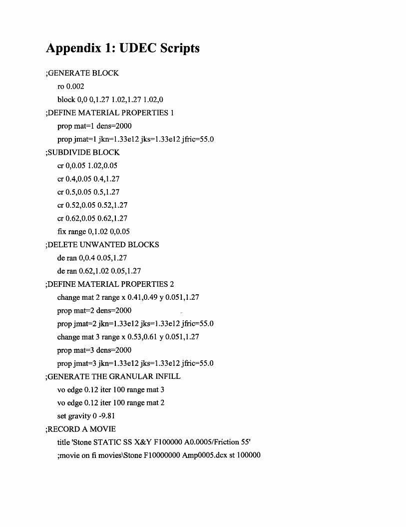
Appendix 1: UDEC Scripts
;GENERATE BLOCK
ro 0.002
block 0,0 0,1.27 1.02,1.27 1.02,0
;DEFINE MATERIAL PROPERTIES 1
prop mat=1 dens=2000
prop jmat=l jkn=l.33el2 jks=1.33el2 jfric=55.0
;SUBDIVIDE BLOCK
cr 0,0.05 1.02,0.05
cr 0.4,0.05 0.4,1.27
cr 0.5,0.05 0.5,1.27
cr 0.52,0.05 0.52,1.27
cr 0.62,0.05 0.62,1.27
fix range 0,1.02 0,0.05
;DELETE UNWANTED BLOCKS
de ran 0,0.4 0.05,1.27
de ran 0.62,1.02 0.05,1.27
;DEFINE MATERIAL PROPERTIES 2
change mat 2 range x 0.41,0.49 y 0.051,1.27
prop mat=2 dens=2000
prop jmat=2 jkn=1.33el2 jks=1.33e12 jfric=55.0
change mat 3 range x 0.53,0.61 y 0.051,1.27
prop mat=3 dens=2000
prop jmat=3 jkn=1.33e12 jks=1.33el2 jfric=55.0
;GENERATE THE GRANULAR INFILL
vo edge 0.12 iter 100 range mat 3
vo edge 0.12 iter 100 range mat 2
set gravity 0 -9.81
;RECORD A MOVIE
title 'Stone STATIC SS X&Y F100000 A0.0005/Friction 55'
;movie on fi movies\Stone F10000000 Amp0005.dcx st 100000

;PLOT VELOCITY
;plot hold block vel
damp 0.0001 0.1
;DEFINE SINOSOIDAL LOADING IN X AND Y
def find block
Jab = b near(0.42, 0.0)
end
find block
def mark time
starttime = time
end
mark time
def pulsel
whilestepping
dytime = time - starttime
xwave = 2.0*pi*freq*ampl*cos(2.0*pi*freq*dytime)
ywave = 2.0*pi*freq*ampl*cos(2.0*pi*freq*dytime)
b_yvel(_iab) = ywave
b_xvel(_iab) = xwave
end
;ENTER LOADING PARAMETERS
set freq=l10 ampl=0.0005
;CREATE A TITLE AND A MOVIE
title 'Stone STATIC SS X&Y F100000 A0.0005/Friction 55'
movie on fi movies\Stone F10000000 Amp0005.dcx st 100000

Appendix 2: Pamphlet Distributed in Kashmir 06This simple pamphlet was developed partially guided by the findings of this research to addressthe needs of those who would have to rebuild their houses without any external support of anykind.
iI~